EP3845456A1 - Two-wheel air cycle machine - Google Patents
Two-wheel air cycle machine Download PDFInfo
- Publication number
- EP3845456A1 EP3845456A1 EP20218003.0A EP20218003A EP3845456A1 EP 3845456 A1 EP3845456 A1 EP 3845456A1 EP 20218003 A EP20218003 A EP 20218003A EP 3845456 A1 EP3845456 A1 EP 3845456A1
- Authority
- EP
- European Patent Office
- Prior art keywords
- compressor
- air cycle
- shaft
- disk
- cycle machine
- Prior art date
- Legal status (The legal status is an assumption and is not a legal conclusion. Google has not performed a legal analysis and makes no representation as to the accuracy of the status listed.)
- Granted
Links
Images


Classifications
-
- F—MECHANICAL ENGINEERING; LIGHTING; HEATING; WEAPONS; BLASTING
- F04—POSITIVE - DISPLACEMENT MACHINES FOR LIQUIDS; PUMPS FOR LIQUIDS OR ELASTIC FLUIDS
- F04D—NON-POSITIVE-DISPLACEMENT PUMPS
- F04D29/00—Details, component parts, or accessories
- F04D29/05—Shafts or bearings, or assemblies thereof, specially adapted for elastic fluid pumps
- F04D29/051—Axial thrust balancing
- F04D29/0516—Axial thrust balancing balancing pistons
-
- F—MECHANICAL ENGINEERING; LIGHTING; HEATING; WEAPONS; BLASTING
- F04—POSITIVE - DISPLACEMENT MACHINES FOR LIQUIDS; PUMPS FOR LIQUIDS OR ELASTIC FLUIDS
- F04D—NON-POSITIVE-DISPLACEMENT PUMPS
- F04D29/00—Details, component parts, or accessories
- F04D29/05—Shafts or bearings, or assemblies thereof, specially adapted for elastic fluid pumps
- F04D29/056—Bearings
- F04D29/057—Bearings hydrostatic; hydrodynamic
-
- B—PERFORMING OPERATIONS; TRANSPORTING
- B64—AIRCRAFT; AVIATION; COSMONAUTICS
- B64D—EQUIPMENT FOR FITTING IN OR TO AIRCRAFT; FLIGHT SUITS; PARACHUTES; ARRANGEMENT OR MOUNTING OF POWER PLANTS OR PROPULSION TRANSMISSIONS IN AIRCRAFT
- B64D13/00—Arrangements or adaptations of air-treatment apparatus for aircraft crew or passengers, or freight space
- B64D13/06—Arrangements or adaptations of air-treatment apparatus for aircraft crew or passengers, or freight space the air being conditioned
-
- F—MECHANICAL ENGINEERING; LIGHTING; HEATING; WEAPONS; BLASTING
- F04—POSITIVE - DISPLACEMENT MACHINES FOR LIQUIDS; PUMPS FOR LIQUIDS OR ELASTIC FLUIDS
- F04D—NON-POSITIVE-DISPLACEMENT PUMPS
- F04D17/00—Radial-flow pumps, e.g. centrifugal pumps; Helico-centrifugal pumps
- F04D17/08—Centrifugal pumps
- F04D17/10—Centrifugal pumps for compressing or evacuating
- F04D17/105—Centrifugal pumps for compressing or evacuating with double suction
-
- F—MECHANICAL ENGINEERING; LIGHTING; HEATING; WEAPONS; BLASTING
- F04—POSITIVE - DISPLACEMENT MACHINES FOR LIQUIDS; PUMPS FOR LIQUIDS OR ELASTIC FLUIDS
- F04D—NON-POSITIVE-DISPLACEMENT PUMPS
- F04D25/00—Pumping installations or systems
- F04D25/02—Units comprising pumps and their driving means
- F04D25/024—Units comprising pumps and their driving means the driving means being assisted by a power recovery turbine
-
- F—MECHANICAL ENGINEERING; LIGHTING; HEATING; WEAPONS; BLASTING
- F04—POSITIVE - DISPLACEMENT MACHINES FOR LIQUIDS; PUMPS FOR LIQUIDS OR ELASTIC FLUIDS
- F04D—NON-POSITIVE-DISPLACEMENT PUMPS
- F04D29/00—Details, component parts, or accessories
- F04D29/05—Shafts or bearings, or assemblies thereof, specially adapted for elastic fluid pumps
- F04D29/053—Shafts
-
- F—MECHANICAL ENGINEERING; LIGHTING; HEATING; WEAPONS; BLASTING
- F04—POSITIVE - DISPLACEMENT MACHINES FOR LIQUIDS; PUMPS FOR LIQUIDS OR ELASTIC FLUIDS
- F04D—NON-POSITIVE-DISPLACEMENT PUMPS
- F04D29/00—Details, component parts, or accessories
- F04D29/08—Sealings
- F04D29/083—Sealings especially adapted for elastic fluid pumps
-
- B—PERFORMING OPERATIONS; TRANSPORTING
- B64—AIRCRAFT; AVIATION; COSMONAUTICS
- B64D—EQUIPMENT FOR FITTING IN OR TO AIRCRAFT; FLIGHT SUITS; PARACHUTES; ARRANGEMENT OR MOUNTING OF POWER PLANTS OR PROPULSION TRANSMISSIONS IN AIRCRAFT
- B64D13/00—Arrangements or adaptations of air-treatment apparatus for aircraft crew or passengers, or freight space
- B64D13/06—Arrangements or adaptations of air-treatment apparatus for aircraft crew or passengers, or freight space the air being conditioned
- B64D2013/0603—Environmental Control Systems
- B64D2013/0648—Environmental Control Systems with energy recovery means, e.g. using turbines
-
- F—MECHANICAL ENGINEERING; LIGHTING; HEATING; WEAPONS; BLASTING
- F05—INDEXING SCHEMES RELATING TO ENGINES OR PUMPS IN VARIOUS SUBCLASSES OF CLASSES F01-F04
- F05B—INDEXING SCHEME RELATING TO WIND, SPRING, WEIGHT, INERTIA OR LIKE MOTORS, TO MACHINES OR ENGINES FOR LIQUIDS COVERED BY SUBCLASSES F03B, F03D AND F03G
- F05B2240/00—Components
- F05B2240/50—Bearings
- F05B2240/53—Hydrodynamic or hydrostatic bearings
-
- F—MECHANICAL ENGINEERING; LIGHTING; HEATING; WEAPONS; BLASTING
- F05—INDEXING SCHEMES RELATING TO ENGINES OR PUMPS IN VARIOUS SUBCLASSES OF CLASSES F01-F04
- F05B—INDEXING SCHEME RELATING TO WIND, SPRING, WEIGHT, INERTIA OR LIKE MOTORS, TO MACHINES OR ENGINES FOR LIQUIDS COVERED BY SUBCLASSES F03B, F03D AND F03G
- F05B2240/00—Components
- F05B2240/57—Seals
-
- Y—GENERAL TAGGING OF NEW TECHNOLOGICAL DEVELOPMENTS; GENERAL TAGGING OF CROSS-SECTIONAL TECHNOLOGIES SPANNING OVER SEVERAL SECTIONS OF THE IPC; TECHNICAL SUBJECTS COVERED BY FORMER USPC CROSS-REFERENCE ART COLLECTIONS [XRACs] AND DIGESTS
- Y02—TECHNOLOGIES OR APPLICATIONS FOR MITIGATION OR ADAPTATION AGAINST CLIMATE CHANGE
- Y02T—CLIMATE CHANGE MITIGATION TECHNOLOGIES RELATED TO TRANSPORTATION
- Y02T50/00—Aeronautics or air transport
- Y02T50/50—On board measures aiming to increase energy efficiency
Definitions
- the disclosed subject matter relates to air cycle machines, and more particularly to sealing arrangements for air cycle machines.
- An ACM may include a centrifugal compressor and a centrifugal turbine mounted for co-rotation on a shaft. Air bearings in the form of journal bearings and thrust bearings are typically used to support rotation of the shaft.
- the centrifugal compressor further compresses partially compressed air, such as bleed air received from a compressor of a gas turbine engine. The compressed air discharges to a downstream heat exchanger or other system before returning to the centrifugal turbine. The compressed air expands in the turbine to thereby drive the compressor.
- the air output from the turbine may be utilized as an air supply for a vehicle, such as the cabin of an aircraft.
- a two-wheel air cycle machine includes a tie rod defining an axis, a turbine mounted on the tie rod, and a compressor mounted on the tie rod and having a rotor portion and a disk portion with at least one aperture.
- the air cycle machine further includes a compressor inlet fluidly connecting the compressor and an inlet air source, at least one thrust bearing disposed between the turbine and the compressor, and a compressor end shaft coaxial with the tie rod and abutting the compressor disk portion.
- the compressor end shaft includes a radially-extending seal disk portion and an axially-extending shaft portion having at least one shaft aperture.
- the at least one disk aperture and the at least one shaft aperture are fluidly connected by a compressor disk cavity defined by a gap between the tie rod and the compressor disk portion.
- the at least one disk aperture, the compressor disk cavity, and the at least one shaft aperture at least partially define a compressor inlet flow path.
- a two-wheel air cycle machine with a low pressure start design is disclosed herein.
- the air cycle machine includes a compressor end shaft with a radially-extending seal disk downstream of the compressor.
- the compressor end shaft and the compressor rotor disk define a generally balanced circumferential compressor inlet flow path along which air fed to the compressor inlet can flow.
- the combination of the seal disk and balanced inlet flow help maintain adequate start up pressure and a balanced thrust load on the bearings of the air cycle machine.
- FIG. 1 is a cross-sectional view of air cycle machine 10, which can be incorporated into environmental control system 12 (represented schematically).
- Air cycle machine 10 has a two-wheel configuration such that it includes turbine section 14 and compressor section 16 mounted on and linked by tie rod 18.
- Turbine section 14 includes turbine shroud 20, turbine housing 22, and turbine rotor 24 rotatable about axis A/tie rod 18.
- Compressor section 16 includes compressor inlet 26, compressor outlet 28, compressor shroud/diffuser 30, compressor rotor 32 rotatable about axis A/tie rod 18, compressor seal plate 34, compressor seal housing 36, and compressor end shaft 38.
- Compressor inlet 26 receives air from an air source (not shown), and the air is compressed by compressor rotor 32. Some of the compressed air can be delivered to compressor outlet 28 and passed along to a separate air supply system, while a remainder of the compressed air is delivered to turbine section 14.
- FIG. 1 further shows bearing system 40 disposed between turbine section 14 and compressor section 16.
- Bearing system 40 generally supports the rotation of tie rod 18 and includes bearing housing 42, bearing shaft 44, journal bearings 46, thrust disk 48, thrust bearings 50 positioned on each side of thrust disk 48, and tie rod support member 52.
- Thrust disk 48 extends radially outward from bearing shaft 44 to counter axial loads from rotors 24, 32 during operation of air cycle machine 10.
- journal bearings 46 and thrust bearings 50 are hydrodynamic fluid bearings. Other suitable bearing types are contemplated herein.
- bearing shaft 44 abuts compressor end shaft 32 at an end nearest the compressor, and abuts turbine rotor 24 at an opposite end.
- Bearing shaft 44 is coaxial with each of tie rod 18 and journal bearings 46, and is disposed concentrically within journal bearings 46.
- Tie rod support member 52 is coaxial with tie rod 18 and is axially aligned with thrust disk 48.
- Bearing shaft can be formed from a corrosion-resistant metallic material, such as stainless steel.
- FIG. 2 is an enlarged cross-sectional view of detail D2 of FIG. 1 showing various elements of compressor section 16 in greater detail.
- Compressor rotor 32 includes a disk portion 32 D and blades 32 B .
- Compressor rotor 32 can be formed from a metallic material, such as titanium.
- a plurality of disk apertures 54 extend through disk portion 32 D near compressor inlet 26.
- Apertures 54 can be evenly circumferentially distributed around disk portion 32 D .
- Apertures 54 fluidly connect compressor inlet 26 and disk cavity 56 defined by a gap between disk portion 32 D and tie rod 18.
- the gap defining cavity 56 is a continuous, annular gap such that disk cavity 56 is also a continuous, annular structure. In alternative embodiments, though, there can be an individual disk cavity 56 associated with each aperture 54.
- Compressor end shaft 3 8 abuts disk portion 32 D on a side opposite compressor inlet 26.
- Compressor end shaft 38 can be formed from a corrosion-resistant metallic material, such as stainless steel.
- Compressor end shaft 38 includes axially-extending shaft portion 58, and radially-extending seal disk portion 60.
- Compressor end shaft 38 includes a plurality of shaft apertures 62 extending radially through shaft portion 58. Although shown in FIG. 2 as radially-extending apertures, shaft apertures 62 can be angled in alternative embodiments. Shaft apertures 62 can be evenly circumferentially distributed around shaft portion 58 of compressor end shaft 38. Shaft apertures 62 fluidly connect disk cavity 56 and seal cavity 64, which is partially defined by seal housing 36 and compressor end shaft 38.
- Seal plate 34 is coaxial with and extends radially away from compressor end shaft 38, and is positioned axially between compressor rotor 32 and seal housing 36. Seal plate 34 abuts a knife edge region 66 (labeled in FIG. 3 ) on shaft portion 58 of compressor end shaft 38. Like compressor end shaft 38, seal plate 34 can be made from a corrosion-resistant stainless steel or other suitable corrosion-resistant material. As shown in FIG. 2 , seal plate 34 has a greater radial extent (from axis A) than either of seal housing 36 or seal disk portion 60 of compressor end shaft 38. In operation of air cycle machine 10, any seal leakage airflow F L (indicated by dashed arrows in FIG. 2 ) can pass between seal plate 34 and seal disk portion 60, and flow generally into the space surrounding bearing system 40.
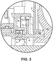
- FIG. 3 is an enlarged cross-sectional view of detail D3 of FIG. 2 showing elements of compressor end shaft 38 and seal housing 36 in greater detail.
- Seal housing 36 supports abradable seals 68, which can be made from a polyimide or other suitable abradable material. One of the abradable seals 68 interacts with knife edge region 70 on seal disk 60. Another, more radially inward abradable seal 68 interacts with knife edge region 72 on bearing shaft 44.
- Seal housing can be formed from a metallic material, such as aluminum. The combination of seal disk portion 60, seal housing 36, and abradable seals 68 creates an enclosed, annular seal cavity 64.
- apertures 54, 62 and cavities 56, 64 allows can optimize pressure and thrust loading at start-up and subsequent operations.
- thrust loading a portion of compressor inlet 26 airflow F I (indicated by solid arrows in FIG. 2 ) serially flows though disk aperture 54, disk cavity 56, shaft aperture 62 and seal cavity 64.
- a representative airflow path is shown in FIG. 2 on only one side of axis A for simplicity, although, it should be understood that such airflow can be circumferentially balanced about the axis to provide balanced airflow and thrust loading.
- Airflow entering seal cavity 64 can be vented back to compressor inlet 26 through ducting or other means, which further allows for balanced thrust loading on thrust bearings 50, as a portion of the compressor inlet airflow is being fed back to the compressor inlet side of air cycle machine 10.
- the total area of the flow path due to number and size of the apertures and cavities can also be selected to maximize pressure to allow for low pressure start-up.
- the various sealing features i.e., seal disk 60, seal plate 34, seal housing 36, and abradable seals 68 also contribute to low pressure start-up as they cooperate to maintain adequate and balanced pressure during operation of air cycle machine 10.
- the disclosed two-wheel air cycle machine has several benefits. Due to the inclusion of compressor end shaft 38 and associated sealing/venting features allows for adequate operating pressurization without the use of a diaphragm valve. Further, the centering of the thrust bearings between the compressor and turbine allows for the air cycle machine to maintain the same overall dimensions as previous models while including the compressor end shaft. In this manner, the disclosed air cycle machine can be used in place of existing models without requiring modification of surrounding componentry.
- a two-wheel air cycle machine includes a tie rod defining an axis, a turbine mounted on the tie rod, and a compressor mounted on the tie rod and having a rotor portion and a disk portion with at least one aperture.
- the air cycle machine further includes a compressor inlet fluidly connecting the compressor and an inlet air source, at least one thrust bearing disposed between the turbine and the compressor, and a compressor end shaft coaxial with the tie rod and abutting the compressor disk portion.
- the compressor end shaft includes a radially-extending seal disk portion and an axially-extending shaft portion having at least one shaft aperture.
- the at least one disk aperture and the at least one shaft aperture are fluidly connected by a compressor disk cavity defined by a gap between the tie rod and the compressor disk portion.
- the at least one disk aperture, the compressor disk cavity, and the at least one shaft aperture at least partially define a compressor inlet flow path.
- the air cycle machine of the preceding paragraph can optionally include, additionally and/or alternatively, any one or more of the following features, configurations and/or additional components:
- the seal disk portion can be a circumferentially continuous structure.
- a radially outermost edge of the seal disk portion can include a knife edge.
- the sealing structure can further include a seal housing coaxial with the compressor end shaft.
- Any of the above air cycle machines can further include a seal plate supported by the seal housing and configured to contact the knife edge of the seal disk portion.
- the seal disk portion and the seal housing can partially define an annular seal cavity.
- the at least one shaft aperture can be a radially-extending aperture fluidly connecting the disk cavity and the seal cavity.
- the seal cavity can be vented to the compressor inlet through ducting.
- the at least one disk aperture can include a plurality of disk apertures distributed circumferentially about the axis.
- the at least one shaft aperture can include a plurality of shaft apertures distributed circumferentially about the axis.
- the at least one shaft aperture can be downstream of the seal disk portion with respect to the compressor inlet airflow path.
- Any of the above air cycle machines can further include a first journal bearing disposed between the compressor and the at least one thrust bearing, and a second journal bearing disposed between the turbine and the at least one thrust bearing.
- Any of the above air cycle machines can further include a bearing shaft coaxial with and supported by the first journal bearing and the second journal bearing.
- a first end of the bearing shaft can abut the compressor end shaft.
- first journal bearing and second journal bearing can be hydrodynamic fluid bearings.
- the at least one thrust bearing can include a first thrust bearing and a second thrust bearing, each being disposed on either side of a thrust runner.
- the first thrust bearing and the second thrust bearing can be hydrodynamic fluid bearings.
- the compressor end shaft can be formed from a corrosion-resistant metallic material.
- the air cycle machine does not include a diaphragm valve.
- the compressor inlet flow path can be symmetrical about the axis.
Landscapes
- Engineering & Computer Science (AREA)
- Mechanical Engineering (AREA)
- General Engineering & Computer Science (AREA)
- Physics & Mathematics (AREA)
- Fluid Mechanics (AREA)
- Health & Medical Sciences (AREA)
- General Health & Medical Sciences (AREA)
- Pulmonology (AREA)
- Aviation & Aerospace Engineering (AREA)
- Structures Of Non-Positive Displacement Pumps (AREA)
Abstract
Description
- The disclosed subject matter relates to air cycle machines, and more particularly to sealing arrangements for air cycle machines.
- Conventional aircraft environmental control systems (ECS) incorporate an air cycle machine (ACM) for cooling and dehumidifying air supplied to an aircraft cabin. An ACM may include a centrifugal compressor and a centrifugal turbine mounted for co-rotation on a shaft. Air bearings in the form of journal bearings and thrust bearings are typically used to support rotation of the shaft. The centrifugal compressor further compresses partially compressed air, such as bleed air received from a compressor of a gas turbine engine. The compressed air discharges to a downstream heat exchanger or other system before returning to the centrifugal turbine. The compressed air expands in the turbine to thereby drive the compressor. The air output from the turbine may be utilized as an air supply for a vehicle, such as the cabin of an aircraft. During start-up of an ACM, friction from thrust loading on the thrust bearings can create resistance in the rotating components of the ACM, thus, it is desirable to reduce and/or balance thrust loading.
- A two-wheel air cycle machine includes a tie rod defining an axis, a turbine mounted on the tie rod, and a compressor mounted on the tie rod and having a rotor portion and a disk portion with at least one aperture. The air cycle machine further includes a compressor inlet fluidly connecting the compressor and an inlet air source, at least one thrust bearing disposed between the turbine and the compressor, and a compressor end shaft coaxial with the tie rod and abutting the compressor disk portion. The compressor end shaft includes a radially-extending seal disk portion and an axially-extending shaft portion having at least one shaft aperture. The at least one disk aperture and the at least one shaft aperture are fluidly connected by a compressor disk cavity defined by a gap between the tie rod and the compressor disk portion. The at least one disk aperture, the compressor disk cavity, and the at least one shaft aperture at least partially define a compressor inlet flow path.
-
-
FIG. 1 is a cross-sectional view of a two-wheel air cycle machine. -
FIG. 2 is an enlarged cross-sectional view of the compressor section of the air cycle machine. -
FIG. 3 is an enlarged cross-sectional view of a portion of a seal plate, compressor end shaft, and seal housing of the air cycle machine. - While the above-identified figures set forth one or more embodiments of the present disclosure, other embodiments are also contemplated, as noted in the discussion. In all cases, this disclosure presents the invention by way of representation and not limitation. It should be understood that numerous other modifications and embodiments can be devised by those skilled in the art, which fall within the scope of the invention as defined by the claims. The figures may not be drawn to scale, and applications and embodiments of the present invention may include features and components not specifically shown in the drawings.
- A two-wheel air cycle machine with a low pressure start design is disclosed herein. The air cycle machine includes a compressor end shaft with a radially-extending seal disk downstream of the compressor. The compressor end shaft and the compressor rotor disk define a generally balanced circumferential compressor inlet flow path along which air fed to the compressor inlet can flow. The combination of the seal disk and balanced inlet flow help maintain adequate start up pressure and a balanced thrust load on the bearings of the air cycle machine.
-
FIG. 1 is a cross-sectional view ofair cycle machine 10, which can be incorporated into environmental control system 12 (represented schematically).Air cycle machine 10 has a two-wheel configuration such that it includesturbine section 14 andcompressor section 16 mounted on and linked bytie rod 18.Turbine section 14 includesturbine shroud 20,turbine housing 22, andturbine rotor 24 rotatable about axis A/tie rod 18.Compressor section 16 includescompressor inlet 26,compressor outlet 28, compressor shroud/diffuser 30,compressor rotor 32 rotatable about axis A/tie rod 18,compressor seal plate 34,compressor seal housing 36, andcompressor end shaft 38.Compressor inlet 26 receives air from an air source (not shown), and the air is compressed bycompressor rotor 32. Some of the compressed air can be delivered tocompressor outlet 28 and passed along to a separate air supply system, while a remainder of the compressed air is delivered toturbine section 14. -
FIG. 1 further shows bearingsystem 40 disposed betweenturbine section 14 andcompressor section 16.Bearing system 40 generally supports the rotation oftie rod 18 and includes bearinghousing 42,bearing shaft 44,journal bearings 46,thrust disk 48,thrust bearings 50 positioned on each side ofthrust disk 48, and tierod support member 52.Thrust disk 48 extends radially outward frombearing shaft 44 to counter axial loads fromrotors air cycle machine 10. In the embodiment shown,journal bearings 46 andthrust bearings 50 are hydrodynamic fluid bearings. Other suitable bearing types are contemplated herein. As can be seen inFIG. 1 , bearingshaft 44 abutscompressor end shaft 32 at an end nearest the compressor, and abutsturbine rotor 24 at an opposite end.Bearing shaft 44 is coaxial with each oftie rod 18 andjournal bearings 46, and is disposed concentrically withinjournal bearings 46. Tierod support member 52 is coaxial withtie rod 18 and is axially aligned withthrust disk 48. Bearing shaft can be formed from a corrosion-resistant metallic material, such as stainless steel. -
FIG. 2 is an enlarged cross-sectional view of detail D2 ofFIG. 1 showing various elements ofcompressor section 16 in greater detail.Compressor rotor 32 includes adisk portion 32D andblades 32B.Compressor rotor 32 can be formed from a metallic material, such as titanium. A plurality ofdisk apertures 54 extend throughdisk portion 32D nearcompressor inlet 26.Apertures 54 can be evenly circumferentially distributed arounddisk portion 32D.Apertures 54 fluidly connectcompressor inlet 26 anddisk cavity 56 defined by a gap betweendisk portion 32D andtie rod 18. In the embodiment shown, thegap defining cavity 56 is a continuous, annular gap such thatdisk cavity 56 is also a continuous, annular structure. In alternative embodiments, though, there can be anindividual disk cavity 56 associated with eachaperture 54. - Compressor end shaft 3 8
abuts disk portion 32D on a sideopposite compressor inlet 26.Compressor end shaft 38 can be formed from a corrosion-resistant metallic material, such as stainless steel.Compressor end shaft 38 includes axially-extendingshaft portion 58, and radially-extendingseal disk portion 60.Compressor end shaft 38 includes a plurality ofshaft apertures 62 extending radially throughshaft portion 58. Although shown inFIG. 2 as radially-extending apertures,shaft apertures 62 can be angled in alternative embodiments.Shaft apertures 62 can be evenly circumferentially distributed aroundshaft portion 58 ofcompressor end shaft 38.Shaft apertures 62 fluidly connectdisk cavity 56 andseal cavity 64, which is partially defined byseal housing 36 andcompressor end shaft 38.Seal plate 34 is coaxial with and extends radially away fromcompressor end shaft 38, and is positioned axially betweencompressor rotor 32 andseal housing 36.Seal plate 34 abuts a knife edge region 66 (labeled inFIG. 3 ) onshaft portion 58 ofcompressor end shaft 38. Likecompressor end shaft 38,seal plate 34 can be made from a corrosion-resistant stainless steel or other suitable corrosion-resistant material. As shown inFIG. 2 ,seal plate 34 has a greater radial extent (from axis A) than either ofseal housing 36 orseal disk portion 60 ofcompressor end shaft 38. In operation ofair cycle machine 10, any seal leakage airflow FL (indicated by dashed arrows inFIG. 2 ) can pass betweenseal plate 34 andseal disk portion 60, and flow generally into the space surroundingbearing system 40. -
FIG. 3 is an enlarged cross-sectional view of detail D3 ofFIG. 2 showing elements ofcompressor end shaft 38 andseal housing 36 in greater detail.Seal housing 36 supports abradable seals 68, which can be made from a polyimide or other suitable abradable material. One of the abradable seals 68 interacts withknife edge region 70 onseal disk 60. Another, more radially inwardabradable seal 68 interacts withknife edge region 72 on bearingshaft 44. Seal housing can be formed from a metallic material, such as aluminum. The combination ofseal disk portion 60, sealhousing 36, andabradable seals 68 creates an enclosed,annular seal cavity 64. - Referring to
FIGS. 2 and3 , the arrangement ofapertures cavities compressor inlet 26 airflow FI (indicated by solid arrows inFIG. 2 ) serially flows thoughdisk aperture 54,disk cavity 56,shaft aperture 62 andseal cavity 64. A representative airflow path is shown inFIG. 2 on only one side of axis A for simplicity, although, it should be understood that such airflow can be circumferentially balanced about the axis to provide balanced airflow and thrust loading. Airflow enteringseal cavity 64 can be vented back tocompressor inlet 26 through ducting or other means, which further allows for balanced thrust loading onthrust bearings 50, as a portion of the compressor inlet airflow is being fed back to the compressor inlet side ofair cycle machine 10. The total area of the flow path due to number and size of the apertures and cavities can also be selected to maximize pressure to allow for low pressure start-up. The various sealing features (i.e.,seal disk 60,seal plate 34, sealhousing 36, and abradable seals 68) also contribute to low pressure start-up as they cooperate to maintain adequate and balanced pressure during operation ofair cycle machine 10. - The disclosed two-wheel air cycle machine has several benefits. Due to the inclusion of
compressor end shaft 38 and associated sealing/venting features allows for adequate operating pressurization without the use of a diaphragm valve. Further, the centering of the thrust bearings between the compressor and turbine allows for the air cycle machine to maintain the same overall dimensions as previous models while including the compressor end shaft. In this manner, the disclosed air cycle machine can be used in place of existing models without requiring modification of surrounding componentry. - Discussion of Possible Embodiments The following are non-exclusive descriptions of possible embodiments of the present invention.
- A two-wheel air cycle machine includes a tie rod defining an axis, a turbine mounted on the tie rod, and a compressor mounted on the tie rod and having a rotor portion and a disk portion with at least one aperture. The air cycle machine further includes a compressor inlet fluidly connecting the compressor and an inlet air source, at least one thrust bearing disposed between the turbine and the compressor, and a compressor end shaft coaxial with the tie rod and abutting the compressor disk portion. The compressor end shaft includes a radially-extending seal disk portion and an axially-extending shaft portion having at least one shaft aperture. The at least one disk aperture and the at least one shaft aperture are fluidly connected by a compressor disk cavity defined by a gap between the tie rod and the compressor disk portion. The at least one disk aperture, the compressor disk cavity, and the at least one shaft aperture at least partially define a compressor inlet flow path.
- The air cycle machine of the preceding paragraph can optionally include, additionally and/or alternatively, any one or more of the following features, configurations and/or additional components:
- In the above air cycle machine, the seal disk portion can be a circumferentially continuous structure.
- In any of the above air cycle machines, a radially outermost edge of the seal disk portion can include a knife edge.
- In any of the above air cycle machines, the sealing structure can further include a seal housing coaxial with the compressor end shaft.
- Any of the above air cycle machines can further include a seal plate supported by the seal housing and configured to contact the knife edge of the seal disk portion.
- In any of the above air cycle machines, the seal disk portion and the seal housing can partially define an annular seal cavity.
- In any of the above air cycle machines, the at least one shaft aperture can be a radially-extending aperture fluidly connecting the disk cavity and the seal cavity.
- In any of the above air cycle machines, the seal cavity can be vented to the compressor inlet through ducting.
- In any of the above air cycle machines, the at least one disk aperture can include a plurality of disk apertures distributed circumferentially about the axis.
- In any of the above air cycle machines, the at least one shaft aperture can include a plurality of shaft apertures distributed circumferentially about the axis.
- In any of the above air cycle machines, the at least one shaft aperture can be downstream of the seal disk portion with respect to the compressor inlet airflow path.
- Any of the above air cycle machines can further include a first journal bearing disposed between the compressor and the at least one thrust bearing, and a second journal bearing disposed between the turbine and the at least one thrust bearing.
- Any of the above air cycle machines can further include a bearing shaft coaxial with and supported by the first journal bearing and the second journal bearing.
- In any of the above air cycle machines, a first end of the bearing shaft can abut the compressor end shaft.
- In any of the above air cycle machines, the first journal bearing and second journal bearing can be hydrodynamic fluid bearings.
- In any of the above air cycle machines, the at least one thrust bearing can include a first thrust bearing and a second thrust bearing, each being disposed on either side of a thrust runner.
- In any of the above air cycle machines, the first thrust bearing and the second thrust bearing can be hydrodynamic fluid bearings.
- In any of the above air cycle machines, the compressor end shaft can be formed from a corrosion-resistant metallic material.
- In any of the above air cycle machines, the air cycle machine does not include a diaphragm valve.
- In any of the above air cycle machines, the compressor inlet flow path can be symmetrical about the axis.
- While the invention has been described with reference to an exemplary embodiment(s), it will be understood by those skilled in the art that various changes may be made without departing from the scope of the invention. Therefore, it is intended that the invention not be limited to the particular embodiment(s) disclosed, but that the invention will include all embodiments falling within the scope of the appended claims.
Claims (15)
- A two-wheel air cycle machine comprising:a tie rod (18) defining an axis;a turbine (14) mounted on the tie rod;a compressor (16) mounted on the tie rod, the compressor comprising a rotor portion (32) and a disk portion (32D) having at least one disk aperture (54);a compressor inlet (26) fluidly connecting the compressor and an inlet air source;at least one thrust bearing (50) disposed between the turbine and the compressor; anda compressor end shaft (38) coaxial with the tie rod and abutting the compressor disk portion, the compressor end shaft comprising a radially-extending seal disk portion (60) and an axially-extending shaft portion (58), the axially extending shaft portion having at least one shaft aperture (62);wherein the at least one disk aperture and the at least one shaft aperture are fluidly connected by a compressor disk cavity (56) defined by a gap between the tie rod and the compressor disk portion; andwherein the at least one disk aperture, the compressor disk cavity, and the at least one shaft aperture at least partially define a compressor inlet flow path.
- The air cycle machine of claim 1, wherein the seal disk portion is a circumferentially continuous structure.
- The air cycle machine of claim 1 or 2, wherein a radially outermost edge of the seal disk portion comprises a knife edge (70).
- The air cycle machine of claim 3, wherein the sealing structure further comprises:
a seal housing (36) coaxial with the compressor end shaft, and optionally further comprising:
a seal plate (34) supported by the seal housing and configured to contact the knife edge (70) of the seal disk portion. - The air cycle machine of claim 4, wherein the seal disk portion and the seal housing partially define an annular seal cavity (64), and optionally wherein the seal cavity is vented to the compressor inlet through ducting.
- The air cycle machine of claim 5, wherein the at least one shaft aperture is a radially-extending aperture fluidly connecting the disk cavity and the seal cavity.
- The air cycle machine of any preceding claim, wherein the at least one disk aperture comprises a plurality of disk apertures distributed circumferentially about the axis.
- The air cycle machine of any preceding claim, wherein the at least one shaft aperture comprises a plurality of shaft apertures distributed circumferentially about the axis.
- The air cycle machine of any preceding claim, wherein the at least one shaft aperture is downstream of the seal disk portion with respect to the compressor inlet airflow path.
- The air cycle machine of any preceding claim and further comprising:a first journal bearing (46) disposed between the compressor and the at least one thrust bearing; anda second journal bearing (46) disposed between the turbine and the at least one thrust bearing; and optionally further comprising:a bearing shaft (44) coaxial with and supported by the first journal bearing and the second journal bearing, and optionally wherein a first end of the bearing shaft abuts the compressor end shaft.
- The air cycle machine of claim 10, wherein the first journal bearing and second journal bearing are hydrodynamic fluid bearings.
- The air cycle machine of any preceding claim, wherein the at least one thrust bearing comprises:
a first thrust bearing and a second thrust bearing, each being disposed on either side of a thrust runner, and optionally wherein the first thrust bearing and the second thrust bearing are hydrodynamic fluid bearings. - The air cycle machine of any preceding claim, wherein the compressor end shaft is formed from a corrosion-resistant metallic material.
- The air cycle machine of any preceding claim, wherein the air cycle machine does not include a diaphragm valve.
- The air cycle machine of any preceding claim, wherein the compressor inlet flow path is symmetrical about the axis.
Applications Claiming Priority (1)
| Application Number | Priority Date | Filing Date | Title |
|---|---|---|---|
| US16/732,754 US11125243B2 (en) | 2020-01-02 | 2020-01-02 | Two-wheel air cycle machine |
Publications (2)
| Publication Number | Publication Date |
|---|---|
| EP3845456A1 true EP3845456A1 (en) | 2021-07-07 |
| EP3845456B1 EP3845456B1 (en) | 2023-09-13 |
Family
ID=74194473
Family Applications (1)
| Application Number | Title | Priority Date | Filing Date |
|---|---|---|---|
| EP20218003.0A Active EP3845456B1 (en) | 2020-01-02 | 2020-12-31 | Two-wheel air cycle machine |
Country Status (2)
| Country | Link |
|---|---|
| US (1) | US11125243B2 (en) |
| EP (1) | EP3845456B1 (en) |
Citations (2)
| Publication number | Priority date | Publication date | Assignee | Title |
|---|---|---|---|---|
| US8734017B1 (en) * | 2013-03-08 | 2014-05-27 | Hamilton Sundstrand Corporation | Air bearing shaft |
| EP3705730A1 (en) * | 2019-03-05 | 2020-09-09 | Hamilton Sundstrand Corporation | Bearing cooling flow for turbine and compressor utilized to supply air for aircraft cabin |
Family Cites Families (13)
| Publication number | Priority date | Publication date | Assignee | Title |
|---|---|---|---|---|
| US5113670A (en) * | 1990-08-03 | 1992-05-19 | United Technologies Corporation | Bearing cooling arrangement for air cycle machine |
| JP2002294571A (en) | 2001-03-30 | 2002-10-09 | Kuraray Co Ltd | Flame retardant leather-like sheet substrate and method for producing the same |
| US6811315B2 (en) * | 2002-12-18 | 2004-11-02 | Pratt & Whitney Canada Corp. | Compliant support for increased load capacity axial thrust bearing |
| US8347647B2 (en) * | 2004-09-22 | 2013-01-08 | Hamilton Sundstrand Corporation | Air cycle machine for an aircraft environmental control system |
| US8496432B2 (en) * | 2010-03-22 | 2013-07-30 | Hamilton Sundstrand Corporation | Thrust bearing cooling path |
| US8905707B2 (en) * | 2010-12-21 | 2014-12-09 | Hamilton Sundstrand Corporation | Bearing cooling control in an air cycle machine |
| US9103568B2 (en) | 2013-08-02 | 2015-08-11 | Hamilton Sundstrand Corporation | Compressor housing for an air cycle machine |
| US9611784B2 (en) | 2013-10-09 | 2017-04-04 | Hamilton Sundstrand Corporation | Insulating seal plate for an air cycle machine |
| US20150233386A1 (en) | 2014-02-14 | 2015-08-20 | Hamilton Sundstrand Corporation | First stage turbine housing for an air cycle machine |
| US9752591B2 (en) * | 2015-01-23 | 2017-09-05 | Carrier Corporation | Compressor diffuser and shroud for a motor driven compressor |
| US10160546B2 (en) | 2015-03-20 | 2018-12-25 | Hamilton Sundstrand Corporation | Air cycle machine with cooling air flow path |
| US10619650B2 (en) | 2016-05-06 | 2020-04-14 | Hamilton Sundstrand Corporation | Air cycle machine fan and compressor housing |
| US11668324B2 (en) * | 2019-08-02 | 2023-06-06 | Hamilton Sundstrand Corporation | Motor and bearing cooling paths and a transfer tube for another cooling channel |
-
2020
- 2020-01-02 US US16/732,754 patent/US11125243B2/en active Active
- 2020-12-31 EP EP20218003.0A patent/EP3845456B1/en active Active
Patent Citations (2)
| Publication number | Priority date | Publication date | Assignee | Title |
|---|---|---|---|---|
| US8734017B1 (en) * | 2013-03-08 | 2014-05-27 | Hamilton Sundstrand Corporation | Air bearing shaft |
| EP3705730A1 (en) * | 2019-03-05 | 2020-09-09 | Hamilton Sundstrand Corporation | Bearing cooling flow for turbine and compressor utilized to supply air for aircraft cabin |
Also Published As
| Publication number | Publication date |
|---|---|
| US11125243B2 (en) | 2021-09-21 |
| US20210207613A1 (en) | 2021-07-08 |
| EP3845456B1 (en) | 2023-09-13 |
Similar Documents
| Publication | Publication Date | Title |
|---|---|---|
| EP3557028B1 (en) | Gas turbine engine | |
| US11215078B2 (en) | Gas turbine engine | |
| US11098731B2 (en) | Grooved shroud casing treatment for high pressure compressor in a turbine engine | |
| US10669893B2 (en) | Air bearing and thermal management nozzle arrangement for interdigitated turbine engine | |
| US10605168B2 (en) | Interdigitated turbine engine air bearing cooling structure and method of thermal management | |
| US10718265B2 (en) | Interdigitated turbine engine air bearing and method of operation | |
| EP2412924B1 (en) | A disk spacer for a gas engine turbine and a method for providing a rotor assembly | |
| EP3460183A1 (en) | Method of clearance control for an interdigitated turbine engine | |
| EP1798419A2 (en) | Thrust bearing arrangement for compressor | |
| CN109477389B (en) | System and method for seals of inboard exhaust circuits in turbines | |
| CN109519238B (en) | Gas turbine engine | |
| US10519774B2 (en) | Rotor arrangement for a turbomachine and compressor | |
| US10787931B2 (en) | Method and structure of interdigitated turbine engine thermal management | |
| US10544734B2 (en) | Three spool gas turbine engine with interdigitated turbine section | |
| US20160362995A1 (en) | Rotor for a turbomachine and compressor | |
| EP3453842A1 (en) | Active clearance control manifold assemblies | |
| CN102537352B (en) | Air cycle machine seal land | |
| EP3436666B1 (en) | Radial turbomachine with axial thrust compensation | |
| CN106246241B (en) | Turbine seal plate | |
| CN108979738B (en) | Sealing system for a turbomachine compressor | |
| US9028220B2 (en) | Tie rod | |
| EP3845456B1 (en) | Two-wheel air cycle machine | |
| EP3179119B1 (en) | Thrust bearing assembly with flow path restriction | |
| US10443416B2 (en) | Casing with suction arm for axial turbine engine | |
| US10294821B2 (en) | Interturbine frame for gas turbine engine |
Legal Events
| Date | Code | Title | Description |
|---|---|---|---|
| PUAI | Public reference made under article 153(3) epc to a published international application that has entered the european phase |
Free format text: ORIGINAL CODE: 0009012 |
|
| STAA | Information on the status of an ep patent application or granted ep patent |
Free format text: STATUS: THE APPLICATION HAS BEEN PUBLISHED |
|
| AK | Designated contracting states |
Kind code of ref document: A1 Designated state(s): AL AT BE BG CH CY CZ DE DK EE ES FI FR GB GR HR HU IE IS IT LI LT LU LV MC MK MT NL NO PL PT RO RS SE SI SK SM TR |
|
| STAA | Information on the status of an ep patent application or granted ep patent |
Free format text: STATUS: REQUEST FOR EXAMINATION WAS MADE |
|
| 17P | Request for examination filed |
Effective date: 20220104 |
|
| RBV | Designated contracting states (corrected) |
Designated state(s): AL AT BE BG CH CY CZ DE DK EE ES FI FR GB GR HR HU IE IS IT LI LT LU LV MC MK MT NL NO PL PT RO RS SE SI SK SM TR |
|
| GRAP | Despatch of communication of intention to grant a patent |
Free format text: ORIGINAL CODE: EPIDOSNIGR1 |
|
| STAA | Information on the status of an ep patent application or granted ep patent |
Free format text: STATUS: GRANT OF PATENT IS INTENDED |
|
| INTG | Intention to grant announced |
Effective date: 20230406 |
|
| GRAS | Grant fee paid |
Free format text: ORIGINAL CODE: EPIDOSNIGR3 |
|
| GRAA | (expected) grant |
Free format text: ORIGINAL CODE: 0009210 |
|
| STAA | Information on the status of an ep patent application or granted ep patent |
Free format text: STATUS: THE PATENT HAS BEEN GRANTED |
|
| AK | Designated contracting states |
Kind code of ref document: B1 Designated state(s): AL AT BE BG CH CY CZ DE DK EE ES FI FR GB GR HR HU IE IS IT LI LT LU LV MC MK MT NL NO PL PT RO RS SE SI SK SM TR |
|
| REG | Reference to a national code |
Ref country code: CH Ref legal event code: EP |
|
| REG | Reference to a national code |
Ref country code: DE Ref legal event code: R096 Ref document number: 602020017588 Country of ref document: DE |
|
| REG | Reference to a national code |
Ref country code: IE Ref legal event code: FG4D |
|
| REG | Reference to a national code |
Ref country code: LT Ref legal event code: MG9D |
|
| REG | Reference to a national code |
Ref country code: NL Ref legal event code: MP Effective date: 20230913 |
|
| PG25 | Lapsed in a contracting state [announced via postgrant information from national office to epo] |
Ref country code: GR Free format text: LAPSE BECAUSE OF FAILURE TO SUBMIT A TRANSLATION OF THE DESCRIPTION OR TO PAY THE FEE WITHIN THE PRESCRIBED TIME-LIMIT Effective date: 20231214 |
|
| PG25 | Lapsed in a contracting state [announced via postgrant information from national office to epo] |
Ref country code: SE Free format text: LAPSE BECAUSE OF FAILURE TO SUBMIT A TRANSLATION OF THE DESCRIPTION OR TO PAY THE FEE WITHIN THE PRESCRIBED TIME-LIMIT Effective date: 20230913 Ref country code: RS Free format text: LAPSE BECAUSE OF FAILURE TO SUBMIT A TRANSLATION OF THE DESCRIPTION OR TO PAY THE FEE WITHIN THE PRESCRIBED TIME-LIMIT Effective date: 20230913 Ref country code: NO Free format text: LAPSE BECAUSE OF FAILURE TO SUBMIT A TRANSLATION OF THE DESCRIPTION OR TO PAY THE FEE WITHIN THE PRESCRIBED TIME-LIMIT Effective date: 20231213 Ref country code: LV Free format text: LAPSE BECAUSE OF FAILURE TO SUBMIT A TRANSLATION OF THE DESCRIPTION OR TO PAY THE FEE WITHIN THE PRESCRIBED TIME-LIMIT Effective date: 20230913 Ref country code: LT Free format text: LAPSE BECAUSE OF FAILURE TO SUBMIT A TRANSLATION OF THE DESCRIPTION OR TO PAY THE FEE WITHIN THE PRESCRIBED TIME-LIMIT Effective date: 20230913 Ref country code: HR Free format text: LAPSE BECAUSE OF FAILURE TO SUBMIT A TRANSLATION OF THE DESCRIPTION OR TO PAY THE FEE WITHIN THE PRESCRIBED TIME-LIMIT Effective date: 20230913 Ref country code: GR Free format text: LAPSE BECAUSE OF FAILURE TO SUBMIT A TRANSLATION OF THE DESCRIPTION OR TO PAY THE FEE WITHIN THE PRESCRIBED TIME-LIMIT Effective date: 20231214 Ref country code: FI Free format text: LAPSE BECAUSE OF FAILURE TO SUBMIT A TRANSLATION OF THE DESCRIPTION OR TO PAY THE FEE WITHIN THE PRESCRIBED TIME-LIMIT Effective date: 20230913 |
|
| REG | Reference to a national code |
Ref country code: AT Ref legal event code: MK05 Ref document number: 1611051 Country of ref document: AT Kind code of ref document: T Effective date: 20230913 |
|
| PG25 | Lapsed in a contracting state [announced via postgrant information from national office to epo] |
Ref country code: NL Free format text: LAPSE BECAUSE OF FAILURE TO SUBMIT A TRANSLATION OF THE DESCRIPTION OR TO PAY THE FEE WITHIN THE PRESCRIBED TIME-LIMIT Effective date: 20230913 |
|
| PG25 | Lapsed in a contracting state [announced via postgrant information from national office to epo] |
Ref country code: IS Free format text: LAPSE BECAUSE OF FAILURE TO SUBMIT A TRANSLATION OF THE DESCRIPTION OR TO PAY THE FEE WITHIN THE PRESCRIBED TIME-LIMIT Effective date: 20240113 |
|
| PG25 | Lapsed in a contracting state [announced via postgrant information from national office to epo] |
Ref country code: AT Free format text: LAPSE BECAUSE OF FAILURE TO SUBMIT A TRANSLATION OF THE DESCRIPTION OR TO PAY THE FEE WITHIN THE PRESCRIBED TIME-LIMIT Effective date: 20230913 |
|
| PG25 | Lapsed in a contracting state [announced via postgrant information from national office to epo] |
Ref country code: ES Free format text: LAPSE BECAUSE OF FAILURE TO SUBMIT A TRANSLATION OF THE DESCRIPTION OR TO PAY THE FEE WITHIN THE PRESCRIBED TIME-LIMIT Effective date: 20230913 |
|
| PG25 | Lapsed in a contracting state [announced via postgrant information from national office to epo] |
Ref country code: SM Free format text: LAPSE BECAUSE OF FAILURE TO SUBMIT A TRANSLATION OF THE DESCRIPTION OR TO PAY THE FEE WITHIN THE PRESCRIBED TIME-LIMIT Effective date: 20230913 Ref country code: RO Free format text: LAPSE BECAUSE OF FAILURE TO SUBMIT A TRANSLATION OF THE DESCRIPTION OR TO PAY THE FEE WITHIN THE PRESCRIBED TIME-LIMIT Effective date: 20230913 Ref country code: IS Free format text: LAPSE BECAUSE OF FAILURE TO SUBMIT A TRANSLATION OF THE DESCRIPTION OR TO PAY THE FEE WITHIN THE PRESCRIBED TIME-LIMIT Effective date: 20240113 Ref country code: ES Free format text: LAPSE BECAUSE OF FAILURE TO SUBMIT A TRANSLATION OF THE DESCRIPTION OR TO PAY THE FEE WITHIN THE PRESCRIBED TIME-LIMIT Effective date: 20230913 Ref country code: EE Free format text: LAPSE BECAUSE OF FAILURE TO SUBMIT A TRANSLATION OF THE DESCRIPTION OR TO PAY THE FEE WITHIN THE PRESCRIBED TIME-LIMIT Effective date: 20230913 Ref country code: CZ Free format text: LAPSE BECAUSE OF FAILURE TO SUBMIT A TRANSLATION OF THE DESCRIPTION OR TO PAY THE FEE WITHIN THE PRESCRIBED TIME-LIMIT Effective date: 20230913 Ref country code: AT Free format text: LAPSE BECAUSE OF FAILURE TO SUBMIT A TRANSLATION OF THE DESCRIPTION OR TO PAY THE FEE WITHIN THE PRESCRIBED TIME-LIMIT Effective date: 20230913 Ref country code: PT Free format text: LAPSE BECAUSE OF FAILURE TO SUBMIT A TRANSLATION OF THE DESCRIPTION OR TO PAY THE FEE WITHIN THE PRESCRIBED TIME-LIMIT Effective date: 20240115 Ref country code: SK Free format text: LAPSE BECAUSE OF FAILURE TO SUBMIT A TRANSLATION OF THE DESCRIPTION OR TO PAY THE FEE WITHIN THE PRESCRIBED TIME-LIMIT Effective date: 20230913 |
|
| PG25 | Lapsed in a contracting state [announced via postgrant information from national office to epo] |
Ref country code: PL Free format text: LAPSE BECAUSE OF FAILURE TO SUBMIT A TRANSLATION OF THE DESCRIPTION OR TO PAY THE FEE WITHIN THE PRESCRIBED TIME-LIMIT Effective date: 20230913 Ref country code: IT Free format text: LAPSE BECAUSE OF FAILURE TO SUBMIT A TRANSLATION OF THE DESCRIPTION OR TO PAY THE FEE WITHIN THE PRESCRIBED TIME-LIMIT Effective date: 20230913 |
|
| REG | Reference to a national code |
Ref country code: DE Ref legal event code: R097 Ref document number: 602020017588 Country of ref document: DE |
|
| PG25 | Lapsed in a contracting state [announced via postgrant information from national office to epo] |
Ref country code: DK Free format text: LAPSE BECAUSE OF FAILURE TO SUBMIT A TRANSLATION OF THE DESCRIPTION OR TO PAY THE FEE WITHIN THE PRESCRIBED TIME-LIMIT Effective date: 20230913 |
|
| PLBE | No opposition filed within time limit |
Free format text: ORIGINAL CODE: 0009261 |
|
| STAA | Information on the status of an ep patent application or granted ep patent |
Free format text: STATUS: NO OPPOSITION FILED WITHIN TIME LIMIT |
|
| PG25 | Lapsed in a contracting state [announced via postgrant information from national office to epo] |
Ref country code: DK Free format text: LAPSE BECAUSE OF FAILURE TO SUBMIT A TRANSLATION OF THE DESCRIPTION OR TO PAY THE FEE WITHIN THE PRESCRIBED TIME-LIMIT Effective date: 20230913 |
|
| REG | Reference to a national code |
Ref country code: CH Ref legal event code: PL |
|
| 26N | No opposition filed |
Effective date: 20240614 |
|
| PG25 | Lapsed in a contracting state [announced via postgrant information from national office to epo] |
Ref country code: LU Free format text: LAPSE BECAUSE OF NON-PAYMENT OF DUE FEES Effective date: 20231231 |
|
| PG25 | Lapsed in a contracting state [announced via postgrant information from national office to epo] |
Ref country code: MC Free format text: LAPSE BECAUSE OF FAILURE TO SUBMIT A TRANSLATION OF THE DESCRIPTION OR TO PAY THE FEE WITHIN THE PRESCRIBED TIME-LIMIT Effective date: 20230913 |
|
| REG | Reference to a national code |
Ref country code: BE Ref legal event code: MM Effective date: 20231231 |
|
| PG25 | Lapsed in a contracting state [announced via postgrant information from national office to epo] |
Ref country code: MC Free format text: LAPSE BECAUSE OF FAILURE TO SUBMIT A TRANSLATION OF THE DESCRIPTION OR TO PAY THE FEE WITHIN THE PRESCRIBED TIME-LIMIT Effective date: 20230913 Ref country code: LU Free format text: LAPSE BECAUSE OF NON-PAYMENT OF DUE FEES Effective date: 20231231 |
|
| REG | Reference to a national code |
Ref country code: IE Ref legal event code: MM4A |
|
| PG25 | Lapsed in a contracting state [announced via postgrant information from national office to epo] |
Ref country code: IE Free format text: LAPSE BECAUSE OF NON-PAYMENT OF DUE FEES Effective date: 20231231 |
|
| PG25 | Lapsed in a contracting state [announced via postgrant information from national office to epo] |
Ref country code: BE Free format text: LAPSE BECAUSE OF NON-PAYMENT OF DUE FEES Effective date: 20231231 |
|
| PG25 | Lapsed in a contracting state [announced via postgrant information from national office to epo] |
Ref country code: CH Free format text: LAPSE BECAUSE OF NON-PAYMENT OF DUE FEES Effective date: 20231231 |
|
| PG25 | Lapsed in a contracting state [announced via postgrant information from national office to epo] |
Ref country code: SI Free format text: LAPSE BECAUSE OF FAILURE TO SUBMIT A TRANSLATION OF THE DESCRIPTION OR TO PAY THE FEE WITHIN THE PRESCRIBED TIME-LIMIT Effective date: 20230913 |
|
| PG25 | Lapsed in a contracting state [announced via postgrant information from national office to epo] |
Ref country code: SI Free format text: LAPSE BECAUSE OF FAILURE TO SUBMIT A TRANSLATION OF THE DESCRIPTION OR TO PAY THE FEE WITHIN THE PRESCRIBED TIME-LIMIT Effective date: 20230913 Ref country code: IE Free format text: LAPSE BECAUSE OF NON-PAYMENT OF DUE FEES Effective date: 20231231 Ref country code: CH Free format text: LAPSE BECAUSE OF NON-PAYMENT OF DUE FEES Effective date: 20231231 Ref country code: BE Free format text: LAPSE BECAUSE OF NON-PAYMENT OF DUE FEES Effective date: 20231231 |
|
| PG25 | Lapsed in a contracting state [announced via postgrant information from national office to epo] |
Ref country code: BG Free format text: LAPSE BECAUSE OF FAILURE TO SUBMIT A TRANSLATION OF THE DESCRIPTION OR TO PAY THE FEE WITHIN THE PRESCRIBED TIME-LIMIT Effective date: 20230913 |
|
| PG25 | Lapsed in a contracting state [announced via postgrant information from national office to epo] |
Ref country code: BG Free format text: LAPSE BECAUSE OF FAILURE TO SUBMIT A TRANSLATION OF THE DESCRIPTION OR TO PAY THE FEE WITHIN THE PRESCRIBED TIME-LIMIT Effective date: 20230913 |
|
| PG25 | Lapsed in a contracting state [announced via postgrant information from national office to epo] |
Ref country code: CY Free format text: LAPSE BECAUSE OF FAILURE TO SUBMIT A TRANSLATION OF THE DESCRIPTION OR TO PAY THE FEE WITHIN THE PRESCRIBED TIME-LIMIT; INVALID AB INITIO Effective date: 20201231 |
|
| PG25 | Lapsed in a contracting state [announced via postgrant information from national office to epo] |
Ref country code: HU Free format text: LAPSE BECAUSE OF FAILURE TO SUBMIT A TRANSLATION OF THE DESCRIPTION OR TO PAY THE FEE WITHIN THE PRESCRIBED TIME-LIMIT; INVALID AB INITIO Effective date: 20201231 |
|
| PG25 | Lapsed in a contracting state [announced via postgrant information from national office to epo] |
Ref country code: TR Free format text: LAPSE BECAUSE OF FAILURE TO SUBMIT A TRANSLATION OF THE DESCRIPTION OR TO PAY THE FEE WITHIN THE PRESCRIBED TIME-LIMIT Effective date: 20230913 |
|
| PGFP | Annual fee paid to national office [announced via postgrant information from national office to epo] |
Ref country code: DE Payment date: 20251126 Year of fee payment: 6 |
|
| PGFP | Annual fee paid to national office [announced via postgrant information from national office to epo] |
Ref country code: GB Payment date: 20251120 Year of fee payment: 6 |
|
| PGFP | Annual fee paid to national office [announced via postgrant information from national office to epo] |
Ref country code: FR Payment date: 20251119 Year of fee payment: 6 |
|
| P01 | Opt-out of the competence of the unified patent court (upc) registered |
Free format text: CASE NUMBER: UPC_APP_0018698_3845456/2025 Effective date: 20251221 |