EP3845258A1 - System and method to lyse and remove red blood cells from a cell product - Google Patents
System and method to lyse and remove red blood cells from a cell product Download PDFInfo
- Publication number
- EP3845258A1 EP3845258A1 EP20216919.9A EP20216919A EP3845258A1 EP 3845258 A1 EP3845258 A1 EP 3845258A1 EP 20216919 A EP20216919 A EP 20216919A EP 3845258 A1 EP3845258 A1 EP 3845258A1
- Authority
- EP
- European Patent Office
- Prior art keywords
- blood cells
- gap
- red blood
- volume
- lysing buffer
- Prior art date
- Legal status (The legal status is an assumption and is not a legal conclusion. Google has not performed a legal analysis and makes no representation as to the accuracy of the status listed.)
- Granted
Links
Images




Classifications
-
- A—HUMAN NECESSITIES
- A61—MEDICAL OR VETERINARY SCIENCE; HYGIENE
- A61M—DEVICES FOR INTRODUCING MEDIA INTO, OR ONTO, THE BODY; DEVICES FOR TRANSDUCING BODY MEDIA OR FOR TAKING MEDIA FROM THE BODY; DEVICES FOR PRODUCING OR ENDING SLEEP OR STUPOR
- A61M1/00—Suction or pumping devices for medical purposes; Devices for carrying-off, for treatment of, or for carrying-over, body-liquids; Drainage systems
- A61M1/36—Other treatment of blood in a by-pass of the natural circulatory system, e.g. temperature adaptation, irradiation ; Extra-corporeal blood circuits
- A61M1/3693—Other treatment of blood in a by-pass of the natural circulatory system, e.g. temperature adaptation, irradiation ; Extra-corporeal blood circuits using separation based on different densities of components, e.g. centrifuging
- A61M1/3698—Expressing processed fluid out from the turning rotor using another fluid compressing the treatment chamber; Variable volume rotors
-
- A—HUMAN NECESSITIES
- A61—MEDICAL OR VETERINARY SCIENCE; HYGIENE
- A61M—DEVICES FOR INTRODUCING MEDIA INTO, OR ONTO, THE BODY; DEVICES FOR TRANSDUCING BODY MEDIA OR FOR TAKING MEDIA FROM THE BODY; DEVICES FOR PRODUCING OR ENDING SLEEP OR STUPOR
- A61M1/00—Suction or pumping devices for medical purposes; Devices for carrying-off, for treatment of, or for carrying-over, body-liquids; Drainage systems
- A61M1/02—Blood transfusion apparatus
- A61M1/0281—Apparatus for treatment of blood or blood constituents prior to transfusion, e.g. washing, filtering or thawing
-
- A—HUMAN NECESSITIES
- A61—MEDICAL OR VETERINARY SCIENCE; HYGIENE
- A61M—DEVICES FOR INTRODUCING MEDIA INTO, OR ONTO, THE BODY; DEVICES FOR TRANSDUCING BODY MEDIA OR FOR TAKING MEDIA FROM THE BODY; DEVICES FOR PRODUCING OR ENDING SLEEP OR STUPOR
- A61M1/00—Suction or pumping devices for medical purposes; Devices for carrying-off, for treatment of, or for carrying-over, body-liquids; Drainage systems
- A61M1/14—Dialysis systems; Artificial kidneys; Blood oxygenators ; Reciprocating systems for treatment of body fluids, e.g. single needle systems for hemofiltration or pheresis
- A61M1/16—Dialysis systems; Artificial kidneys; Blood oxygenators ; Reciprocating systems for treatment of body fluids, e.g. single needle systems for hemofiltration or pheresis with membranes
- A61M1/26—Dialysis systems; Artificial kidneys; Blood oxygenators ; Reciprocating systems for treatment of body fluids, e.g. single needle systems for hemofiltration or pheresis with membranes and internal elements which are moving
- A61M1/262—Dialysis systems; Artificial kidneys; Blood oxygenators ; Reciprocating systems for treatment of body fluids, e.g. single needle systems for hemofiltration or pheresis with membranes and internal elements which are moving rotating
- A61M1/265—Dialysis systems; Artificial kidneys; Blood oxygenators ; Reciprocating systems for treatment of body fluids, e.g. single needle systems for hemofiltration or pheresis with membranes and internal elements which are moving rotating inducing Taylor vortices
-
- A—HUMAN NECESSITIES
- A61—MEDICAL OR VETERINARY SCIENCE; HYGIENE
- A61M—DEVICES FOR INTRODUCING MEDIA INTO, OR ONTO, THE BODY; DEVICES FOR TRANSDUCING BODY MEDIA OR FOR TAKING MEDIA FROM THE BODY; DEVICES FOR PRODUCING OR ENDING SLEEP OR STUPOR
- A61M1/00—Suction or pumping devices for medical purposes; Devices for carrying-off, for treatment of, or for carrying-over, body-liquids; Drainage systems
- A61M1/34—Filtering material out of the blood by passing it through a membrane, i.e. hemofiltration or diafiltration
- A61M1/3472—Filtering material out of the blood by passing it through a membrane, i.e. hemofiltration or diafiltration with treatment of the filtrate
- A61M1/3486—Biological, chemical treatment, e.g. chemical precipitation; treatment by absorbents
-
- A—HUMAN NECESSITIES
- A61—MEDICAL OR VETERINARY SCIENCE; HYGIENE
- A61M—DEVICES FOR INTRODUCING MEDIA INTO, OR ONTO, THE BODY; DEVICES FOR TRANSDUCING BODY MEDIA OR FOR TAKING MEDIA FROM THE BODY; DEVICES FOR PRODUCING OR ENDING SLEEP OR STUPOR
- A61M1/00—Suction or pumping devices for medical purposes; Devices for carrying-off, for treatment of, or for carrying-over, body-liquids; Drainage systems
- A61M1/36—Other treatment of blood in a by-pass of the natural circulatory system, e.g. temperature adaptation, irradiation ; Extra-corporeal blood circuits
- A61M1/3621—Extra-corporeal blood circuits
- A61M1/3622—Extra-corporeal blood circuits with a cassette forming partially or totally the blood circuit
- A61M1/36222—Details related to the interface between cassette and machine
- A61M1/362227—Details related to the interface between cassette and machine the interface providing means for actuating on functional elements of the cassette, e.g. plungers
-
- A—HUMAN NECESSITIES
- A61—MEDICAL OR VETERINARY SCIENCE; HYGIENE
- A61M—DEVICES FOR INTRODUCING MEDIA INTO, OR ONTO, THE BODY; DEVICES FOR TRANSDUCING BODY MEDIA OR FOR TAKING MEDIA FROM THE BODY; DEVICES FOR PRODUCING OR ENDING SLEEP OR STUPOR
- A61M1/00—Suction or pumping devices for medical purposes; Devices for carrying-off, for treatment of, or for carrying-over, body-liquids; Drainage systems
- A61M1/36—Other treatment of blood in a by-pass of the natural circulatory system, e.g. temperature adaptation, irradiation ; Extra-corporeal blood circuits
- A61M1/3621—Extra-corporeal blood circuits
- A61M1/3622—Extra-corporeal blood circuits with a cassette forming partially or totally the blood circuit
- A61M1/36226—Constructional details of cassettes, e.g. specific details on material or shape
- A61M1/362265—Details of valves
-
- A—HUMAN NECESSITIES
- A61—MEDICAL OR VETERINARY SCIENCE; HYGIENE
- A61M—DEVICES FOR INTRODUCING MEDIA INTO, OR ONTO, THE BODY; DEVICES FOR TRANSDUCING BODY MEDIA OR FOR TAKING MEDIA FROM THE BODY; DEVICES FOR PRODUCING OR ENDING SLEEP OR STUPOR
- A61M1/00—Suction or pumping devices for medical purposes; Devices for carrying-off, for treatment of, or for carrying-over, body-liquids; Drainage systems
- A61M1/36—Other treatment of blood in a by-pass of the natural circulatory system, e.g. temperature adaptation, irradiation ; Extra-corporeal blood circuits
- A61M1/3621—Extra-corporeal blood circuits
- A61M1/3622—Extra-corporeal blood circuits with a cassette forming partially or totally the blood circuit
- A61M1/36226—Constructional details of cassettes, e.g. specific details on material or shape
- A61M1/362266—Means for adding solutions or substances to the blood
-
- A—HUMAN NECESSITIES
- A61—MEDICAL OR VETERINARY SCIENCE; HYGIENE
- A61M—DEVICES FOR INTRODUCING MEDIA INTO, OR ONTO, THE BODY; DEVICES FOR TRANSDUCING BODY MEDIA OR FOR TAKING MEDIA FROM THE BODY; DEVICES FOR PRODUCING OR ENDING SLEEP OR STUPOR
- A61M1/00—Suction or pumping devices for medical purposes; Devices for carrying-off, for treatment of, or for carrying-over, body-liquids; Drainage systems
- A61M1/36—Other treatment of blood in a by-pass of the natural circulatory system, e.g. temperature adaptation, irradiation ; Extra-corporeal blood circuits
- A61M1/3692—Washing or rinsing blood or blood constituents
-
- C—CHEMISTRY; METALLURGY
- C12—BIOCHEMISTRY; BEER; SPIRITS; WINE; VINEGAR; MICROBIOLOGY; ENZYMOLOGY; MUTATION OR GENETIC ENGINEERING
- C12N—MICROORGANISMS OR ENZYMES; COMPOSITIONS THEREOF; PROPAGATING, PRESERVING, OR MAINTAINING MICROORGANISMS; MUTATION OR GENETIC ENGINEERING; CULTURE MEDIA
- C12N5/00—Undifferentiated human, animal or plant cells, e.g. cell lines; Tissues; Cultivation or maintenance thereof; Culture media therefor
- C12N5/06—Animal cells or tissues; Human cells or tissues
- C12N5/0602—Vertebrate cells
- C12N5/0634—Cells from the blood or the immune system
-
- G—PHYSICS
- G01—MEASURING; TESTING
- G01N—INVESTIGATING OR ANALYSING MATERIALS BY DETERMINING THEIR CHEMICAL OR PHYSICAL PROPERTIES
- G01N33/00—Investigating or analysing materials by specific methods not covered by groups G01N1/00 - G01N31/00
- G01N33/48—Biological material, e.g. blood, urine; Haemocytometers
- G01N33/50—Chemical analysis of biological material, e.g. blood, urine; Testing involving biospecific ligand binding methods; Immunological testing
- G01N33/5002—Partitioning blood components
-
- A—HUMAN NECESSITIES
- A61—MEDICAL OR VETERINARY SCIENCE; HYGIENE
- A61M—DEVICES FOR INTRODUCING MEDIA INTO, OR ONTO, THE BODY; DEVICES FOR TRANSDUCING BODY MEDIA OR FOR TAKING MEDIA FROM THE BODY; DEVICES FOR PRODUCING OR ENDING SLEEP OR STUPOR
- A61M1/00—Suction or pumping devices for medical purposes; Devices for carrying-off, for treatment of, or for carrying-over, body-liquids; Drainage systems
- A61M1/36—Other treatment of blood in a by-pass of the natural circulatory system, e.g. temperature adaptation, irradiation ; Extra-corporeal blood circuits
- A61M1/3621—Extra-corporeal blood circuits
- A61M1/3622—Extra-corporeal blood circuits with a cassette forming partially or totally the blood circuit
- A61M1/36224—Extra-corporeal blood circuits with a cassette forming partially or totally the blood circuit with sensing means or components thereof
-
- A—HUMAN NECESSITIES
- A61—MEDICAL OR VETERINARY SCIENCE; HYGIENE
- A61M—DEVICES FOR INTRODUCING MEDIA INTO, OR ONTO, THE BODY; DEVICES FOR TRANSDUCING BODY MEDIA OR FOR TAKING MEDIA FROM THE BODY; DEVICES FOR PRODUCING OR ENDING SLEEP OR STUPOR
- A61M1/00—Suction or pumping devices for medical purposes; Devices for carrying-off, for treatment of, or for carrying-over, body-liquids; Drainage systems
- A61M1/36—Other treatment of blood in a by-pass of the natural circulatory system, e.g. temperature adaptation, irradiation ; Extra-corporeal blood circuits
- A61M1/3621—Extra-corporeal blood circuits
- A61M1/3622—Extra-corporeal blood circuits with a cassette forming partially or totally the blood circuit
- A61M1/36225—Extra-corporeal blood circuits with a cassette forming partially or totally the blood circuit with blood pumping means or components thereof
-
- A—HUMAN NECESSITIES
- A61—MEDICAL OR VETERINARY SCIENCE; HYGIENE
- A61M—DEVICES FOR INTRODUCING MEDIA INTO, OR ONTO, THE BODY; DEVICES FOR TRANSDUCING BODY MEDIA OR FOR TAKING MEDIA FROM THE BODY; DEVICES FOR PRODUCING OR ENDING SLEEP OR STUPOR
- A61M2202/00—Special media to be introduced, removed or treated
- A61M2202/04—Liquids
- A61M2202/0413—Blood
- A61M2202/0429—Red blood cells; Erythrocytes
Definitions
- Cell therapy involves the administration of living cells that have been manipulated or processed ex vivo. In the manufacture of cellular therapies, there is a need to isolate certain cells to continue to work with the desired or target cell within that population.
- An apheresis product contains red blood cells (RBCs), a buffy coat layer (containing WBCs and platelets), and plasma.
- RBCs red blood cells
- buffy coat layer containing WBCs and platelets
- plasma plasma.
- RBCs and platelets interfere with many of the selection technologies, so removal of these cell types is often one of the first steps of the manufacturing processes.
- Platelets can be removed by several established devices that use, for example, centrifuges or spinning membranes for separation.
- RBC removal there are few methods available for RBC removal.
- One such method is the Ficoll-Paque gradient protocol, which uses Ficoll-Paque to create a density gradient of the apheresis product. This typically involves an operator using a pipette to manually remove the buffy coat layer that includes the WBCs from the gradient. This process is cumbersome, time consuming, and operator dependent.
- a method for removing red blood cells from a suspension comprising red blood cells, white blood cells, platelets and plasma.
- the method uses a spinning membrane separator that comprises a housing, a rotor rotatably supported within the housing, a membrane affixed to the rotor having a porous surface that permits plasma and platelets to pass therethrough but not red blood cells and white blood cells, with a gap being defined between the housing and the membrane.
- the method comprises the steps of: a) flowing whole blood into the gap; b) collecting red blood cells and white blood cells in the gap and passing plasma and platelets through the membrane; c) introducing a first quantity of lysing buffer into the gap; d) incubating the red blood cells, white blood cells and lysing buffer in the gap for a period of time to cause a lysis reaction with the red blood cells; e) introducing a second quantity of lysing buffer into the gap to displace the first quantity of lysing buffer and a first quantity of red blood cell debris out of the gap and through the membrane; f) introducing a first quantity of wash buffer into the gap to quench the lysis reaction and displace the second quantity of lysing buffer and a second quantity of red blood cell debris out of the gap and through the membrane; and g) introducing a second quantity of wash buffer into the gap to flow washed white blood cells out of the housing.
- the spinning membrane separator comprises a housing having a first port/inlet, a second port/filtrate outlet and a third port/retentate outlet
- the method comprises the steps of a) flowing whole blood through the first port/inlet into the gap; b) closing the third port/retentate outlet and opening the second port/filtrate outlet to collect red blood cells and white blood cells in the gap and pass plasma and platelets through the membrane and out through the second port/filtrate outlet; c) flowing a first quantity of lysing buffer through the first port/inlet into the gap to displace the supernatant out through the second port/filtrate outlet; d) closing the second port/filtrate outlet and incubating the red blood cells, white blood cells and lysing buffer in the gap for a period of time to cause a lysis reaction with the red blood cells; e) opening the second port/filtrate outlet and flowing a second quantity of lysing buffer through the first port/inlet into the gap to displace
- the method further comprises rotating the membrane at an idle speed during the incubation of the red blood cells, white blood cells and lysing buffer in the gap.
- the idle speed is a rate of rotation of the membrane sufficient to gently mix the cells in the lysing buffer, and is a rate at which cells in the gap do not form Taylor vortices.
- the spinning membrane separator has a known interior volume, and the first and second volume of lysing buffer and the first volume of wash buffer is equal to the interior volume of the spinning membrane separator.
- the method comprises establishing a total time for steps c), d) and e) based on a time limit for exposure to lysing buffer recommended by a producer of the lysing buffer.
- a volume for the gap is established and the method comprises introducing whole blood into the gap until a packed cell volume of the whole blood reaches a predetermined percentage of the volume of the gap, based on the optimal ratio of lysing buffer to cells.
- a system in a sixth aspect, includes a disposable fluid flow circuit including a spinning membrane separator and a reusable hardware component that includes a programmable controller programmed to automatically flow fluids through the spinning membrane separator and open and close the various ports to perform the methods of the aspects set forth above.
- a method and associated system are disclosed that provide for the automated removal of RBCs from a suspension, such as whole blood, that includes the target cells using a spinning membrane separator.
- the method generally involves first concentrating the RBCs in the gap between the spinning membrane and the separator housing, and then introducing the lysing buffer. More specifically, for the concentration step, spinning membrane filtration can be used to first concentrate the WBCs and RBCs.
- a filter membrane having a 4um pore size can be used to filter out the supernatant, which would comprise platelets and plasma, from an apheresis product.
- the cells greater than 4um are built up in the gap of the spinning membrane separator, and not permitted to exit the outlet port of the separator housing. Because the volume of the spinning membrane separator is a fixed, known volume, the volume of the apheresis product to be introduced into the spinning membrane separator for concentration is determined by using the cell concentration and volume input from the apheresis product. Consequently, the RBCs and WBCs are concentrated into a small volume.
- the lysing buffer is introduced to fill the rest of the space within the spinner.
- the system is controlled so that the ratio of lysing buffer to RBC + WBC suspension meets the specifications of the manufacturer of the lysing buffer.
- the recommended ratio of the volume of lysing buffer to the volume of the RBC pellet is 8-10:1.
- different lysing buffer manufacturers can recommend different volume to cell suspension ratios.
- the suspension of lysing buffer, RBCs and WBCs is then incubated in situ in the spinning membrane separator to cause a lysis reaction with the RBCs. Additional lysing solution is then introduced into the separator to displace the spent lysing solution and RBC debris out of the gap.
- the total amount of time for the RBCs and WBCs to be exposed to the lysing buffer is dependent on the kind of lysing buffer used. A total residence time is typically recommended by the manufacturer, and the total time for exposure to lysing solution should be less than the total time recommended by the manufacturer in order to avoid damage to the WBCs.
- a wash buffer is introduced into the separator to quench the lysis reaction and to displace the additional lysing buffer and RBC debris out of the gap. Additional wash buffer is then introduced into the gap to flow the washed WBCs out of the housing and into, e.g., a collection container.
- Fig. 1 schematically illustrates a system generally designated 10, for performing the automated removal of RBCs from a suspension such as whole blood in accordance with the present disclosure.
- the system 10 includes a disposable fluid flow circuit and a reusable hardware component.
- the disposable fluid flow circuit includes a spinning membrane separator 12, such as is well known in the art, a cassette 14 for providing fluid management through the kit, and syringes 16 and 18 for moving fluid through the kit.
- An exemplary spinning membrane separator is shown and described in US 9,381,291 .
- the reusable hardware component includes a drive system for the spinning membrane separator (not shown), syringe drivers/pumps 20, 22 for actuating the syringes 16, 18, respectively, weigh scales 24, 26, 28, 30 and 32, various actuators (not shown) for opening and closing valves/clamps associated with the cassette (described in greater detail below), and a programmable controller 34 for automatically operating the system.
- the syringe drivers/pumps may be as described in US 2018/0155070 , incorporated herein by reference, and may include an array of position detectors 36 positioned along the length of the syringe barrel 38 that determine the position of the plunger head 40 of the syringe within the barrel of the syringe.
- the position detectors 36 are coupled to the controller 34 and may comprise transmitters that emit light and receivers that receive light reflected back to the receiver from the plunger head. This provides an indication of the volume of fluid moved by the syringe through the fluid flow circuit.
- the spinning membrane separator 12 comprises a housing 12a having a rotor 12b rotatably mounted therein and to which a porous membrane is secured, with a gap 12c being defined between the interior surface of the housing 12a and the surface of the porous membrane.
- the housing 12a includes an inlet 42 through which the suspension of cellular material and other fluids are introduced into the separator 12, a first outlet 44 for flowing retentate (the target cells) out of the separator 12 and a second outlet 46 for flowing filtrate (waste) out of the separator 12.
- the disposable fluid flow circuit additionally includes a first container 48 for wash buffer, a second container 50 for lysing buffer, a third container 52 for the source suspension (e.g., previously collected whole blood from which the target cells are to be obtained), a fourth container 54 for receiving the retentate (i.e., the target cells), and a fifth container 56 for receiving the filtrate (i.e., the waste).
- a first container 48 for wash buffer e.g., a second container 50 for lysing buffer
- a third container 52 for the source suspension e.g., previously collected whole blood from which the target cells are to be obtained
- a fourth container 54 for receiving the retentate (i.e., the target cells)
- a fifth container 56 for receiving the filtrate (i.e., the waste).
- These containers 48, 50, 52, 54 and 56 are supported by weigh scales 24, 26, 28, 30 and 32, respectively, which send signals to the controller 34.
- the cassette 14 comprises a housing 58 having a series of fluid pathways therein interconnecting the various other components of the disposable kit.
- Each fluid pathway includes a flow control mechanism, such as valves or clamps, that are automatically operated by the controller based on signals received from the various detectors, sensors and scales of the system.
- the cassette 14 includes a first fluid pathway 60 with a first inlet 62 configured to be in fluid communication with the first container 48 (of wash media), a second fluid pathway 64 with a second inlet 66 configured to be in fluid communication with the second container 50 (of lysing buffer), a third fluid pathway 68 with a third inlet 70 configured to be in fluid communication with the third container 52 (of source material), a fourth fluid pathway 72 with a fourth inlet 74 configured to be in fluid communication with the fourth container 54 (for the retentate/target cells), and a fifth fluid pathway 76 with a fifth inlet 78 configured to be in fluid communication with the fifth container 56 (for the filtrate/waste).
- Devices for selectively occluding the fluid pathways are associated with each of the fluid pathways for selectively occluding the fluid pathways.
- Such occluding devices may take the form of valves or clamps.
- a valve or clamp 80, 82, 84, 86 and 88 is respectively associated with each of the first, second, third, fourth and fifth inlets 62, 66, 70, 74, and 78 of the cassette 14.
- An additional valve or clamp 90, 92 is associated with each of the fourth and fifth flow paths 72, 76 to control flow out from the first and second outlets 44, 46 of the spinning membrane separator 12.
- Sensors 94 are also provided that are able to detect differences in the fluid passing by. Specifically, the sensors 94 are able to detect interfaces between different types of fluids, such as an air-liquid interface, a wash media-retentate interface, and a wash media-filtrate interface. Upon detection of such interfaces, a signal is sent to the controller 34 that will act to control the configuration of the valves/clamps (open or closed) and actuate the syringe pumps to move fluid through the kit.
- the cassette may also include a pressure sensor 96 for monitoring purposes.
- the separation and collection procedure may commence.
- the procedure is automatically controlled by means of the programmable controller, which sequentially operates the valves/clamps and the syringe pumps/drivers in accordance with signals received from the sensors.
- the spinning membrane separator may first be primed (not shown), by flowing wash buffer therethrough. Then, the system is operated to introduce the source media into the spinning membrane separator, with the cellular material (red blood cells and white blood cells) being allowed to build up in the separator and the supernatant being drawn out of the separator.
- the amount of source media (whole blood) to be introduced into the spinning membrane separator may be a predetermined percentage of the volume of the gap in the spinning membrane separator between the housing and surface of the membrane, with whole blood being introduced into the gap of the spinning membrane separator until the packed cell volume of the whole blood reaches the predetermined percentage.
- the filter membrane of the spinning membrane separator will have a pore size of approximately 4 ⁇ m.
- the packed cell volume of platelets is not considered, as the platelets will pass through the membrane along with the plasma.
- the packed cell volume is a function of the concentration of white blood cells and red blood cells in the source media.
- the volume of the gap of the spinning membrane separator must be sufficient to accommodate the packed cell volume of the red blood cells and white blood cells retained therein, plus the volume of lysing solution at the ratio recommended by the manufacturer.
- clamps 80, 82, 88 and 90 are closed to prevent fluid flow through flow paths 60, 64 and 76.
- Clamps 84 and 92 are opened, and the syringe drive 22 is actuated to withdraw the plunger head 40 associated with syringe 18 to draw the source media out of the container 52 through the fluid flow path 68 and into the spinning membrane separator through the inlet 42.
- the cellular components being unable to pass through the filter membrane, will build up in the gap between the membrane and the housing of the separator, while the supernatant (platelets and plasma) that passes through the membrane is flowed out through the outlet 46 of the spinning membrane separator 12 through the flow path 76 and into the barrel 38 of syringe 18.
- the clamp 84 is closed.
- the supernatant drawn into the syringe 18 may be flowed to the waste container 56.
- clamp 92 is closed and clamp 88 opened, and the syringe driver 22 actuated to return the plunger head 40 to its original position to flow the supernatant through the flow path 76 out of the cassette 14 through inlet 78 and into the container 56.
- lysing buffer is then introduced into the spinning membrane separator 12 to wash out any supernatant (platelets and plasma) remaining on the separator after performing the steps illustrated in Figs. 2 and 3 .
- clamps 84 and 88 are closed, clamps 80 and 90 remain closed, clamp 82 is opened, and clamp 92 either remains open, if the step of Fig. 3 is not performed, or is opened, if the step of Fig. 3 is performed.
- the syringe driver 22 is then actuated to draw the plunger head 40 of syringe 18 into the barrel 38 of the syringe, thus drawing lysing solution out of the container 50, into the cassette 14 through inlet 66, through flow path 64 and into the spinning membrane separator through inlet 42.
- the lysing solution will displace the remaining platelets and plasma from the housing of the spinning membrane separator through the flow path 76 and into the barrel of the syringe 18.
- the quantity of lysing solution to be introduced into the separator will be predetermined and is a multiple of the volume of cells retained in the separator based upon the ration recommended by the producer of the lysing solution.
- spinning membrane separator should be selected to have an interior volume that accommodates the total volume of the concentrated cells and the lysing solution.
- the remaining platelets and plasma displaced by the lysing solution that is drawn into the syringe 18 may be flowed to the waste container 56, as described above with reference to Fig. 3 .
- the cells are then allowed to incubate in the lysing solution within the housing of the spinning membrane separator to cause a lysis reaction with the red blood cells.
- clamps 82 and 92 are closed, while clamps 80, 84 and 90 remain closed, to retain the concentrated cells and lysing solution within the spinning membrane separator.
- the membrane of the separator is preferably rotated at an idle speed, that being a rate of rotation below that at which Taylor vortices would be formed in the gap between the housing and the spinning membrane, to gently mix the cells in the lysing buffer.
- the cells within the spinning membrane separator are then rinsed with lysing buffer to help ensure that the lysing buffer interacts with all of the red blood cells, as well as washing out the red blood cell debris that was generated.
- the red blood cell debris comprises fragments of the red blood cells which are of a size to pass through the membrane.
- the syringe driver 22 is then actuated to draw the plunger head 40 of syringe 18 further into the barrel 38 of the syringe, thus drawing lysing solution out of the container 50, into the cassette 14 through inlet 66, through flow path 64 and into the spinning membrane separator through inlet 42.
- the quantity of lysing buffer introduced during this rinsing step may be equal to the interior volume of the spinning membrane separator.
- the lysing buffer and red blood cell debris displaced by the lysing solution that is drawn into the syringe 18 when the cells are rinsed with lysing buffer may be flowed to the waste container 56, as described above with reference to Fig. 3 .
- the total time for performing the steps illustrated in Figs. 4 , 5 and 6 , during which the concentrated cells retained in the spinning membrane separator are exposed to the lysing solution should be predetermined and based on a time limit exposure to lysing buffer recommended by the producer of the lysing buffer. This value can either be pre-programmed into the controller or input into the controller by the operator prior to commencement of the procedure.
- wash buffer is introduced into the spinning membrane separator to quench the lysis reaction and to further displace the red blood cell fragments and lysing buffer out of the separator.
- clamp 82 is closed and clamp 80 opened, while clamps 84, 88 and 90 remain closed, and the syringe driver 22 again actuated to further draw the plunger head 40 of syringe 18 further into the barrel 38 of the syringe, thus drawing wash buffer out of the container 48, into the cassette 14 through inlet 62, through flow path 60 and into the spinning membrane separator through inlet 42, with the lysing buffer used for rinsing being drawn into the barrel of the syringe 18.
- the quantity of wash buffer introduced during this rinsing step may be equal to the interior volume of the spinning membrane separator.
- the lysing buffer displaced by the wash buffer that is drawn into the syringe 18 may be flowed to the waste container 56, as described above with reference to Fig. 3 .
- the washed cells are then harvested from the spinning membrane separator into the syringe 16 by opening clamp 90 and closing clamps 86 and 92, while clamps 82 and 84 remain closed, and clamp 80 remains open.
- the syringe driver 20 is then actuated to draw the plunger head 40 of syringe 16 into the barrel 38 of the syringe, thus drawing additional wash buffer out of the container 48, into the cassette 14 through inlet 62, through flow path 60 and into the spinning membrane separator through inlet 42.
- the wash buffer displaces the washed cells out of the spinning membrane separator 12 through outlet 44, through flow path 72, and into the barrel of syringe 16. Wash buffer may be drawn from the container 48 until an interface between the washed cells and the wash buffer is detected by the interface detector 94 associated with flow path 72.
- the harvested cells are pushed to the collection container 54 by closing clamp 90, opening clamp 86, and actuating the syringe driver 20 actuated to return the plunger head 40 of syringe 16 to its original position to flow the washed cells through the flow path 72 out of the cassette 14 through inlet 68 and into the container 54.
- the harvested white blood cells substantially free of any red blood cells, are then ready for further processing.
- the volumes of fluid moved through the fluid flow circuit can be determined based on signals received from the weigh scales for the various containers and/or signals received from the position detectors for the plunger head associated with the syringe drivers and the interface detectors.
- the method is susceptible to automation, with the controller automatically opening and closing the appropriate clamps and actuating the syringe drivers based on such signals.
- the volume of the spinning membrane separator is 18 mLs
- the apheresis volume is 100 mLs
- the RBC hematocrit of the apheresis volume is 2%
- the WBC concentration is 2.5E7 cells/mL.
- the system first calculates the volume of cells concentrated and determines if that volume plus 5 times that volume can fit in the spinner (assuming that the recommended ratio of the volume of lysing buffer to the volume of the RBC cell suspension is 5:1. This multiplication factor must be configurable to accommodate for other lysing buffer types.).
- the system shall incubate the suspension for a prescribed period. After this incubation period is reached in the spinner, a series of rinses to the spinning membrane separator is introduced. The initial rinse is done with lysing buffer to increase the probability of the buffer interacting with all of the RBCs. Some of the RBC fragments will wash through the 4um pores with this rinse. The total amount of time of this rinse plus the incubation time shall be less than the residence time recommended by the lysing buffer manufacturer. Then, to stop the effects of the lysing buffer, a second rinse is done with a wash buffer which washes out any more RBC debris that was generated and any lysing buffer that remains in the cell suspension.
Landscapes
- Health & Medical Sciences (AREA)
- Engineering & Computer Science (AREA)
- Heart & Thoracic Surgery (AREA)
- Life Sciences & Earth Sciences (AREA)
- Biomedical Technology (AREA)
- Vascular Medicine (AREA)
- Hematology (AREA)
- General Health & Medical Sciences (AREA)
- Public Health (AREA)
- Veterinary Medicine (AREA)
- Animal Behavior & Ethology (AREA)
- Anesthesiology (AREA)
- Cardiology (AREA)
- Chemical & Material Sciences (AREA)
- Biotechnology (AREA)
- Cell Biology (AREA)
- Genetics & Genomics (AREA)
- Urology & Nephrology (AREA)
- Zoology (AREA)
- Wood Science & Technology (AREA)
- Bioinformatics & Cheminformatics (AREA)
- Immunology (AREA)
- Organic Chemistry (AREA)
- Molecular Biology (AREA)
- Biochemistry (AREA)
- Microbiology (AREA)
- General Engineering & Computer Science (AREA)
- Biodiversity & Conservation Biology (AREA)
- Emergency Medicine (AREA)
- Food Science & Technology (AREA)
- Medicinal Chemistry (AREA)
- Physics & Mathematics (AREA)
- Analytical Chemistry (AREA)
- General Physics & Mathematics (AREA)
- Pathology (AREA)
- External Artificial Organs (AREA)
Abstract
Description
- Cell therapy involves the administration of living cells that have been manipulated or processed ex vivo. In the manufacture of cellular therapies, there is a need to isolate certain cells to continue to work with the desired or target cell within that population.
- The starting point for many cellular therapy manufacturing processes is an apheresis product. An apheresis product contains red blood cells (RBCs), a buffy coat layer (containing WBCs and platelets), and plasma. In many manufacturing processes, there is a specific type of WBC that needs to be isolated. RBCs and platelets interfere with many of the selection technologies, so removal of these cell types is often one of the first steps of the manufacturing processes.
- Platelets can be removed by several established devices that use, for example, centrifuges or spinning membranes for separation. However, there are few methods available for RBC removal. One such method is the Ficoll-Paque gradient protocol, which uses Ficoll-Paque to create a density gradient of the apheresis product. This typically involves an operator using a pipette to manually remove the buffy coat layer that includes the WBCs from the gradient. This process is cumbersome, time consuming, and operator dependent.
- Other methods include lysing the RBCs with lysing buffers, and then separating the RBC debris from the WBCs layer. This also has been a manual process, and one that may require a large volume of lysing buffer, as most lysing buffers require a high ratio of buffer to RBC cell suspension to properly lyse the RBCs. The larger the starting apheresis volume, the more lysing buffer is needed. Also, if WBCs are in contact with the lysing buffer for extended periods of time their structure can be harmed.
- Therefore, there is a need to develop a method to remove RBCs from a cell product that requires less operator intervention and is susceptible to automation, has repeatable results, requires less material usage, and does not harm the target cells.
- The methods and systems described herein have several aspects. In a first aspect, a method is provided for removing red blood cells from a suspension comprising red blood cells, white blood cells, platelets and plasma. The method uses a spinning membrane separator that comprises a housing, a rotor rotatably supported within the housing, a membrane affixed to the rotor having a porous surface that permits plasma and platelets to pass therethrough but not red blood cells and white blood cells, with a gap being defined between the housing and the membrane.
- The method comprises the steps of: a) flowing whole blood into the gap; b) collecting red blood cells and white blood cells in the gap and passing plasma and platelets through the membrane; c) introducing a first quantity of lysing buffer into the gap; d) incubating the red blood cells, white blood cells and lysing buffer in the gap for a period of time to cause a lysis reaction with the red blood cells; e) introducing a second quantity of lysing buffer into the gap to displace the first quantity of lysing buffer and a first quantity of red blood cell debris out of the gap and through the membrane; f) introducing a first quantity of wash buffer into the gap to quench the lysis reaction and displace the second quantity of lysing buffer and a second quantity of red blood cell debris out of the gap and through the membrane; and g) introducing a second quantity of wash buffer into the gap to flow washed white blood cells out of the housing.
- In a related aspect, the spinning membrane separator comprises a housing having a first port/inlet, a second port/filtrate outlet and a third port/retentate outlet, and the method comprises the steps of a) flowing whole blood through the first port/inlet into the gap; b) closing the third port/retentate outlet and opening the second port/filtrate outlet to collect red blood cells and white blood cells in the gap and pass plasma and platelets through the membrane and out through the second port/filtrate outlet; c) flowing a first quantity of lysing buffer through the first port/inlet into the gap to displace the supernatant out through the second port/filtrate outlet; d) closing the second port/filtrate outlet and incubating the red blood cells, white blood cells and lysing buffer in the gap for a period of time to cause a lysis reaction with the red blood cells; e) opening the second port/filtrate outlet and flowing a second quantity of lysing buffer through the first port/inlet into the gap to displace the first quantity of lysing buffer and a first quantity of red blood cell debris out through the second port/filtrate outlet; f) flowing a first quantity of wash buffer through the first port/inlet into the gap to quench the lysis reaction and displace the second quantity of lysing buffer and a second quantity of red blood cell debris out through the second port/filtrate outlet; and g) closing the second port/filtrate outlet, opening the third port/retentate outlet, and flowing a second quantity of wash buffer through the first port/inlet into the gap to flow washed white blood cells out through the third port/retentate outlet.
- In a second aspect, the method further comprises rotating the membrane at an idle speed during the incubation of the red blood cells, white blood cells and lysing buffer in the gap. Preferably, the idle speed is a rate of rotation of the membrane sufficient to gently mix the cells in the lysing buffer, and is a rate at which cells in the gap do not form Taylor vortices.
- In a third aspect, the spinning membrane separator has a known interior volume, and the first and second volume of lysing buffer and the first volume of wash buffer is equal to the interior volume of the spinning membrane separator.
- In a fourth aspect, the method comprises establishing a total time for steps c), d) and e) based on a time limit for exposure to lysing buffer recommended by a producer of the lysing buffer.
- In a fifth aspect, a volume for the gap is established and the method comprises introducing whole blood into the gap until a packed cell volume of the whole blood reaches a predetermined percentage of the volume of the gap, based on the optimal ratio of lysing buffer to cells.
- In a sixth aspect, a system is provided that includes a disposable fluid flow circuit including a spinning membrane separator and a reusable hardware component that includes a programmable controller programmed to automatically flow fluids through the spinning membrane separator and open and close the various ports to perform the methods of the aspects set forth above.
-
-
Fig. 1 is a schematic representation of a system including a spinning membrane separator for performing the automated removal of RBCs from a suspension such as whole blood in accordance with the present disclosure. -
Fig. 2 illustrates the first step of the method in the context of the system shown inFig. 1 in which cells are concentrated in the spinning membrane separator. -
Fig. 3 illustrates an optional step that may follow the first step ofFig. 2 in which the filtrate or waste created in the first step is diverted to a waste container. -
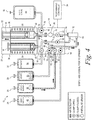
Fig. 4 illustrates the second step of the method in which lysing buffer is added to the spinning membrane separator. -
Fig. 5 illustrates the third step of the method in which the retained cells and lysing solution are incubated inside the spinning membrane separator. -
Fig. 6 illustrates the fourth step of the method in which the cells retained inside the spinning membrane separator are rinsed with lysing buffer. -
Fig. 7 illustrates the fifth step of thee method in which the cells retained inside the spinning membrane separator are rinsed with a wash buffer. -
Fig. 8 illustrates the sixth step of the method in which the washed cells are harvested from the spinning membrane separator. -
Fig. 9 illustrates a seventh step in which the harvested cells are pushed to the final product container and the filtrate is pushed to the waste container. -
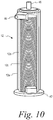
Fig. 10 is a perspective view of a spinning member separator enlarged to show detail. - By way of the present application, a method and associated system are disclosed that provide for the automated removal of RBCs from a suspension, such as whole blood, that includes the target cells using a spinning membrane separator. The method generally involves first concentrating the RBCs in the gap between the spinning membrane and the separator housing, and then introducing the lysing buffer. More specifically, for the concentration step, spinning membrane filtration can be used to first concentrate the WBCs and RBCs. A filter membrane having a 4um pore size can be used to filter out the supernatant, which would comprise platelets and plasma, from an apheresis product.
- For the lysing application, the cells greater than 4um are built up in the gap of the spinning membrane separator, and not permitted to exit the outlet port of the separator housing. Because the volume of the spinning membrane separator is a fixed, known volume, the volume of the apheresis product to be introduced into the spinning membrane separator for concentration is determined by using the cell concentration and volume input from the apheresis product. Consequently, the RBCs and WBCs are concentrated into a small volume.
- Then the lysing buffer is introduced to fill the rest of the space within the spinner. The system is controlled so that the ratio of lysing buffer to RBC + WBC suspension meets the specifications of the manufacturer of the lysing buffer. For example, for ZAPR™ lysing buffer, manufactured by Incell Corporation of San Antonio, Texas, the recommended ratio of the volume of lysing buffer to the volume of the RBC pellet is 8-10:1. However, different lysing buffer manufacturers can recommend different volume to cell suspension ratios.
- The suspension of lysing buffer, RBCs and WBCs is then incubated in situ in the spinning membrane separator to cause a lysis reaction with the RBCs. Additional lysing solution is then introduced into the separator to displace the spent lysing solution and RBC debris out of the gap. The total amount of time for the RBCs and WBCs to be exposed to the lysing buffer is dependent on the kind of lysing buffer used. A total residence time is typically recommended by the manufacturer, and the total time for exposure to lysing solution should be less than the total time recommended by the manufacturer in order to avoid damage to the WBCs. After the desired total exposure time has elapsed, a wash buffer is introduced into the separator to quench the lysis reaction and to displace the additional lysing buffer and RBC debris out of the gap. Additional wash buffer is then introduced into the gap to flow the washed WBCs out of the housing and into, e.g., a collection container.
- With reference to the drawings,
Fig. 1 schematically illustrates a system generally designated 10, for performing the automated removal of RBCs from a suspension such as whole blood in accordance with the present disclosure. Thesystem 10 includes a disposable fluid flow circuit and a reusable hardware component. The disposable fluid flow circuit includes aspinning membrane separator 12, such as is well known in the art, acassette 14 for providing fluid management through the kit, andsyringes US 9,381,291 - The reusable hardware component includes a drive system for the spinning membrane separator (not shown), syringe drivers/
pumps syringes weigh scales programmable controller 34 for automatically operating the system. - The syringe drivers/pumps may be as described in
US 2018/0155070 , incorporated herein by reference, and may include an array ofposition detectors 36 positioned along the length of thesyringe barrel 38 that determine the position of theplunger head 40 of the syringe within the barrel of the syringe. Theposition detectors 36 are coupled to thecontroller 34 and may comprise transmitters that emit light and receivers that receive light reflected back to the receiver from the plunger head. This provides an indication of the volume of fluid moved by the syringe through the fluid flow circuit. - Returning to the fluid flow circuit, as illustrated, the spinning
membrane separator 12 comprises ahousing 12a having arotor 12b rotatably mounted therein and to which a porous membrane is secured, with agap 12c being defined between the interior surface of thehousing 12a and the surface of the porous membrane. Thehousing 12a includes aninlet 42 through which the suspension of cellular material and other fluids are introduced into theseparator 12, afirst outlet 44 for flowing retentate (the target cells) out of theseparator 12 and asecond outlet 46 for flowing filtrate (waste) out of theseparator 12. The disposable fluid flow circuit additionally includes afirst container 48 for wash buffer, asecond container 50 for lysing buffer, athird container 52 for the source suspension (e.g., previously collected whole blood from which the target cells are to be obtained), afourth container 54 for receiving the retentate (i.e., the target cells), and afifth container 56 for receiving the filtrate (i.e., the waste). Thesecontainers weigh scales controller 34. - Fluid management through the flow circuit is controlled by means of the
cassette 14. Thecassette 14 comprises ahousing 58 having a series of fluid pathways therein interconnecting the various other components of the disposable kit. Each fluid pathway includes a flow control mechanism, such as valves or clamps, that are automatically operated by the controller based on signals received from the various detectors, sensors and scales of the system. - Specifically, the
cassette 14 includes afirst fluid pathway 60 with afirst inlet 62 configured to be in fluid communication with the first container 48 (of wash media), asecond fluid pathway 64 with asecond inlet 66 configured to be in fluid communication with the second container 50 (of lysing buffer), a thirdfluid pathway 68 with athird inlet 70 configured to be in fluid communication with the third container 52 (of source material), afourth fluid pathway 72 with afourth inlet 74 configured to be in fluid communication with the fourth container 54 (for the retentate/target cells), and afifth fluid pathway 76 with afifth inlet 78 configured to be in fluid communication with the fifth container 56 (for the filtrate/waste). - Devices for selectively occluding the fluid pathways are associated with each of the fluid pathways for selectively occluding the fluid pathways. Such occluding devices may take the form of valves or clamps. A valve or clamp 80, 82, 84, 86 and 88 is respectively associated with each of the first, second, third, fourth and
fifth inlets cassette 14. An additional valve or clamp 90, 92 is associated with each of the fourth andfifth flow paths second outlets membrane separator 12. -
Sensors 94 are also provided that are able to detect differences in the fluid passing by. Specifically, thesensors 94 are able to detect interfaces between different types of fluids, such as an air-liquid interface, a wash media-retentate interface, and a wash media-filtrate interface. Upon detection of such interfaces, a signal is sent to thecontroller 34 that will act to control the configuration of the valves/clamps (open or closed) and actuate the syringe pumps to move fluid through the kit. The cassette may also include apressure sensor 96 for monitoring purposes. - Operation of the system to provide a suspension of target cells substantially free of red blood cells will now be described. Once the fluid flow circuit is loaded onto the hardware component, with the containers of wash buffer, lysing buffer, and source media attached to their respective flow paths (the empty containers for the receipt of the retentate and waste may be pre-attached to the cassette), and all the containers are suspended on their weigh scales, the separation and collection procedure may commence. As is appreciated, the procedure is automatically controlled by means of the programmable controller, which sequentially operates the valves/clamps and the syringe pumps/drivers in accordance with signals received from the sensors.
- The spinning membrane separator may first be primed (not shown), by flowing wash buffer therethrough. Then, the system is operated to introduce the source media into the spinning membrane separator, with the cellular material (red blood cells and white blood cells) being allowed to build up in the separator and the supernatant being drawn out of the separator. The amount of source media (whole blood) to be introduced into the spinning membrane separator may be a predetermined percentage of the volume of the gap in the spinning membrane separator between the housing and surface of the membrane, with whole blood being introduced into the gap of the spinning membrane separator until the packed cell volume of the whole blood reaches the predetermined percentage.
- The total packed cell volume for a source media including red blood cells, white blood cells and platelets is as follows:

- For the present purposes, the filter membrane of the spinning membrane separator will have a pore size of approximately 4 µm. As only white blood cells and red blood cells have cell diameters greater than (>) 4 µm, the packed cell volume of platelets is not considered, as the platelets will pass through the membrane along with the plasma. Thus, for a given volume of source media the total packed cell volume may be determined as follows:

- The packed cell volume is a function of the concentration of white blood cells and red blood cells in the source media. The total WBC volume and RBC volume for a given volume of source media may be determined as follows:


- By way of example, for a source media having a volume of 100 mLs with a WBC concentration of 10E6 cells/mL and a RBC concentration of 10E6 cells/mL, the packed cell volume may be calculated as follows:


- As can be appreciated, the volume of the gap of the spinning membrane separator must be sufficient to accommodate the packed cell volume of the red blood cells and white blood cells retained therein, plus the volume of lysing solution at the ratio recommended by the manufacturer.
- With reference to
Fig. 2 , clamps 80, 82, 88 and 90 are closed to prevent fluid flow throughflow paths Clamps syringe drive 22 is actuated to withdraw theplunger head 40 associated withsyringe 18 to draw the source media out of thecontainer 52 through thefluid flow path 68 and into the spinning membrane separator through theinlet 42. The cellular components, being unable to pass through the filter membrane, will build up in the gap between the membrane and the housing of the separator, while the supernatant (platelets and plasma) that passes through the membrane is flowed out through theoutlet 46 of the spinningmembrane separator 12 through theflow path 76 and into thebarrel 38 ofsyringe 18. Once the desired volume of concentrated cells in the separator is obtained (discussed in greater detail below), theclamp 84 is closed. - Optionally, and with reference to
Fig. 3 , the supernatant drawn into thesyringe 18 may be flowed to thewaste container 56. To this end, clamp 92 is closed and clamp 88 opened, and thesyringe driver 22 actuated to return theplunger head 40 to its original position to flow the supernatant through theflow path 76 out of thecassette 14 throughinlet 78 and into thecontainer 56. This permits the full volume of the syringe to be available for receiving the lysing buffer and wash media generated in the subsequent steps of the method. - With reference to
Fig. 4 , lysing buffer is then introduced into the spinningmembrane separator 12 to wash out any supernatant (platelets and plasma) remaining on the separator after performing the steps illustrated inFigs. 2 and3 . To this end, clamps 84 and 88 are closed, clamps 80 and 90 remain closed, clamp 82 is opened, and clamp 92 either remains open, if the step ofFig. 3 is not performed, or is opened, if the step ofFig. 3 is performed. Thesyringe driver 22 is then actuated to draw theplunger head 40 ofsyringe 18 into thebarrel 38 of the syringe, thus drawing lysing solution out of thecontainer 50, into thecassette 14 throughinlet 66, throughflow path 64 and into the spinning membrane separator throughinlet 42. The lysing solution will displace the remaining platelets and plasma from the housing of the spinning membrane separator through theflow path 76 and into the barrel of thesyringe 18. The quantity of lysing solution to be introduced into the separator will be predetermined and is a multiple of the volume of cells retained in the separator based upon the ration recommended by the producer of the lysing solution. In this regard, spinning membrane separator should be selected to have an interior volume that accommodates the total volume of the concentrated cells and the lysing solution. Optionally, the remaining platelets and plasma displaced by the lysing solution that is drawn into thesyringe 18 may be flowed to thewaste container 56, as described above with reference toFig. 3 . - The cells are then allowed to incubate in the lysing solution within the housing of the spinning membrane separator to cause a lysis reaction with the red blood cells. With reference to
Fig. 5 , clamps 82 and 92 are closed, whileclamps - The cells within the spinning membrane separator are then rinsed with lysing buffer to help ensure that the lysing buffer interacts with all of the red blood cells, as well as washing out the red blood cell debris that was generated. The red blood cell debris comprises fragments of the red blood cells which are of a size to pass through the membrane. To this end, and with reference to
Fig. 6 , clamps 80, 84, 88 and 90 remain closed, and clamps 82 and 92 are opened. Thesyringe driver 22 is then actuated to draw theplunger head 40 ofsyringe 18 further into thebarrel 38 of the syringe, thus drawing lysing solution out of thecontainer 50, into thecassette 14 throughinlet 66, throughflow path 64 and into the spinning membrane separator throughinlet 42. The quantity of lysing buffer introduced during this rinsing step may be equal to the interior volume of the spinning membrane separator. Optionally, the lysing buffer and red blood cell debris displaced by the lysing solution that is drawn into thesyringe 18 when the cells are rinsed with lysing buffer may be flowed to thewaste container 56, as described above with reference toFig. 3 . - The total time for performing the steps illustrated in
Figs. 4 ,5 and6 , during which the concentrated cells retained in the spinning membrane separator are exposed to the lysing solution should be predetermined and based on a time limit exposure to lysing buffer recommended by the producer of the lysing buffer. This value can either be pre-programmed into the controller or input into the controller by the operator prior to commencement of the procedure. - Then, wash buffer is introduced into the spinning membrane separator to quench the lysis reaction and to further displace the red blood cell fragments and lysing buffer out of the separator. To this end, and as illustrated in
Fig. 7 , clamp 82 is closed and clamp 80 opened, whileclamps syringe driver 22 again actuated to further draw theplunger head 40 ofsyringe 18 further into thebarrel 38 of the syringe, thus drawing wash buffer out of thecontainer 48, into thecassette 14 throughinlet 62, throughflow path 60 and into the spinning membrane separator throughinlet 42, with the lysing buffer used for rinsing being drawn into the barrel of thesyringe 18. The quantity of wash buffer introduced during this rinsing step may be equal to the interior volume of the spinning membrane separator. Optionally, the lysing buffer displaced by the wash buffer that is drawn into thesyringe 18 may be flowed to thewaste container 56, as described above with reference toFig. 3 . - With reference to
Fig. 8 , the washed cells are then harvested from the spinning membrane separator into thesyringe 16 by openingclamp 90 and closing clamps 86 and 92, whileclamps syringe driver 20 is then actuated to draw theplunger head 40 ofsyringe 16 into thebarrel 38 of the syringe, thus drawing additional wash buffer out of thecontainer 48, into thecassette 14 throughinlet 62, throughflow path 60 and into the spinning membrane separator throughinlet 42. The wash buffer displaces the washed cells out of the spinningmembrane separator 12 throughoutlet 44, throughflow path 72, and into the barrel ofsyringe 16. Wash buffer may be drawn from thecontainer 48 until an interface between the washed cells and the wash buffer is detected by theinterface detector 94 associated withflow path 72. - Then, with reference to
Fig. 9 , the harvested cells are pushed to thecollection container 54 by closingclamp 90, openingclamp 86, and actuating thesyringe driver 20 actuated to return theplunger head 40 ofsyringe 16 to its original position to flow the washed cells through theflow path 72 out of thecassette 14 throughinlet 68 and into thecontainer 54. The harvested white blood cells, substantially free of any red blood cells, are then ready for further processing. - As can be appreciated, the volumes of fluid moved through the fluid flow circuit can be determined based on signals received from the weigh scales for the various containers and/or signals received from the position detectors for the plunger head associated with the syringe drivers and the interface detectors. Thus, with the programmer configured to receive signals from the weigh scales, position detectors, and interface detectors, the method is susceptible to automation, with the controller automatically opening and closing the appropriate clamps and actuating the syringe drivers based on such signals.
- A hypothetical example follows, where the volume of the spinning membrane separator is 18 mLs, the apheresis volume is 100 mLs, the RBC hematocrit of the apheresis volume is 2% and the WBC concentration is 2.5E7 cells/mL.
- The system first calculates the volume of cells concentrated and determines if that volume plus 5 times that volume can fit in the spinner (assuming that the recommended ratio of the volume of lysing buffer to the volume of the RBC cell suspension is 5:1. This multiplication factor must be configurable to accommodate for other lysing buffer types.). With these inputs, the volume of RBCs present in the 100mL apheresis is (100*0.02) = 2mL, while the total WBC volume is ∼1mL, using 400fL as the average WBC cell volume. Therefore, total volume of concentrated RBCs and WBCs = 3mLs. The volume of lysing buffer needed to adequately lyse the RBCs is 5x3mLs = 15mLs. Total volume is 18mLs, which is the volume of the spinner. Therefore, the full 100mLs will be pulled into the spinner and separated before the introduction of the lysing buffer.
- Once the correct ratio of cells to lysing buffer is reached in the spinning membrane separator, the system shall incubate the suspension for a prescribed period. After this incubation period is reached in the spinner, a series of rinses to the spinning membrane separator is introduced. The initial rinse is done with lysing buffer to increase the probability of the buffer interacting with all of the RBCs. Some of the RBC fragments will wash through the 4um pores with this rinse. The total amount of time of this rinse plus the incubation time shall be less than the residence time recommended by the lysing buffer manufacturer. Then, to stop the effects of the lysing buffer, a second rinse is done with a wash buffer which washes out any more RBC debris that was generated and any lysing buffer that remains in the cell suspension.
- After the rinses are complete and the lysing buffer has been washed out, additional wash buffer is introduced into the spinning membrane separator to harvest the WBCs into the final product bag. As a consequence, less lysing buffer is used, operator intervention is reduced, and the time required will be less using this automated method when compared with manual lysing techniques.
- Thus, a system and method for lysing and removing red blood cells from a cell product has been provided. It will be understood that the embodiment described above is illustrative of some of the applications of the principles of the present subject matter. Numerous modifications may be made by those skilled in the art without departing from the spirit and scope of the claimed subject matter, including combinations of features that are individually disclosed or claimed herein.
Claims (8)
- A method for removing red blood cells from a suspension comprising red blood cells, white blood cells, platelets and plasma using a spinning membrane separator, the spinning membrane separator comprising a housing, a rotor rotatably supported within the housing, a membrane affixed to the rotor having a porous surface that permits plasma and platelets to pass therethrough but not red blood cells and white blood cells, with a gap being defined between the housing and the membrane, the method comprising:a) flowing whole blood into the gap;b) collecting red blood cells and white blood cells in the gap and passing plasma and platelets through the membrane;c) introducing a first quantity of lysing buffer into the gap;d) incubating the red blood cells, white blood cells and lysing buffer in the gap for a period of time to cause a lysis reaction with the red blood cells;e) introducing a second quantity of lysing buffer into the gap to displace the first quantity of lysing buffer and a first quantity of red blood cell debris out of the gap and through the membrane;f) introducing a first quantity of wash buffer into the gap to quench the lysis reaction and displace the second quantity of lysing buffer and a second quantity of red blood cell debris out of the gap and through the membrane; andg) introducing a second quantity of wash buffer into the gap to flow washed white blood cells out of the housing.
- The method of claim 1 further comprising rotating the membrane at an idle speed during the incubation of the red blood cells, white blood cells and lysing buffer in the gap.
- The method of claim 2 wherein the idle speed is a rate of rotation of the membrane at which cells in the gap do not form Taylor vortices.
- The method of claim 1 wherein the spinning membrane separator has a known interior volume, and the first and second volume of lysing buffer and the first volume of wash buffer is equal to the interior volume of the spinning membrane separator.
- The method of claim 1 further comprising establishing a total time for steps c), d) and e) based on a time limit for exposure to lysing buffer recommended by a producer of the lysing buffer.
- The method of claim 1 wherein a volume for the gap is established and whole blood is introduced into the gap until a packed cell volume of the whole blood reaches a predetermined percentage of the volume of the gap.
- A system for lysing and removing red blood cells from a cell product comprising a disposable fluid flow circuit and a reusable hardware component:a) the disposable fluid flow circuit further comprising i) a spinning membrane separator having housing with a first port/inlet, a second port/filtrate outlet, a third port/retentate outlet, a rotor rotatably supported within the housing, a membrane affixed to the rotor having a porous surface that permits supernatant/plasma and platelets to pass therethrough but not red blood cells and white blood cells, with a gap being defined between the housing and the membrane, ii) a first container of wash media, a second container of lysing buffer, a third container of source media comprising red blood cells and white blood cells, a fourth container for receiving retentate and a fifth container for receiving waste/filtrate; iii) a flow control cassette for directing fluid flow from the first, second and third containers through the spinning membrane separator and to the fourth and fifth containers, the flow control cassette further including a) internal flow paths in fluid communication with each of the first-fifth containers and the first-third ports of the spinning membrane separator, b) valves/clamps associated with the fluid flow paths for controlling flow therethrough, and c) interface detectors;b) the reusable hardware component comprising first and second pumps for moving fluid from the first-third containers through the flow paths in the flow control cassette and into the fourth and fifth containers, volume sensors associated with each of the first and second pumps for measuring the volume of fluid pumped, a weigh scale associated with each of the first-fifth containers, and a programmable controller programmed to automatically perform the method of any one of claims 1-7 based on signals received from the interface detectors and one or both of the volume sensors associated with the pumps and the weigh scales associated with the first-fifth containers.
- The system of claim 7 wherein each of the first and second pumps comprises a syringe pump and the volume sensors comprise position detectors associated with each syringe pump.
Applications Claiming Priority (1)
| Application Number | Priority Date | Filing Date | Title |
|---|---|---|---|
| US202062956760P | 2020-01-03 | 2020-01-03 |
Publications (3)
| Publication Number | Publication Date |
|---|---|
| EP3845258A1 true EP3845258A1 (en) | 2021-07-07 |
| EP3845258B1 EP3845258B1 (en) | 2025-02-05 |
| EP3845258C0 EP3845258C0 (en) | 2025-02-05 |
Family
ID=73857054
Family Applications (1)
| Application Number | Title | Priority Date | Filing Date |
|---|---|---|---|
| EP20216919.9A Active EP3845258B1 (en) | 2020-01-03 | 2020-12-23 | System and method to lyse and remove red blood cells from a cell product |
Country Status (2)
| Country | Link |
|---|---|
| US (1) | US11623034B2 (en) |
| EP (1) | EP3845258B1 (en) |
Cited By (1)
| Publication number | Priority date | Publication date | Assignee | Title |
|---|---|---|---|---|
| CN114636818A (en) * | 2022-05-19 | 2022-06-17 | 天津德祥生物技术有限公司 | Coating liquid, erythrocyte membrane coating liquid containing coating liquid and application of erythrocyte membrane coating liquid |
Families Citing this family (1)
| Publication number | Priority date | Publication date | Assignee | Title |
|---|---|---|---|---|
| US12661650B2 (en) | 2024-02-27 | 2026-06-23 | Aridica Corporation | PBMC separation systems and methods of use |
Citations (7)
| Publication number | Priority date | Publication date | Assignee | Title |
|---|---|---|---|---|
| WO2002004921A2 (en) * | 2000-07-07 | 2002-01-17 | Coulter International Corp. | Apparatus and method for biological sample preparation and analysis |
| WO2012125460A1 (en) * | 2011-03-11 | 2012-09-20 | Fenwal, Inc. | Membrane separation devices, systems and methods employing same, and data management systems and methods |
| WO2012154257A1 (en) * | 2011-02-17 | 2012-11-15 | Prometheus Laboratories Inc. | Apparatus and method for isolating leukocytes and tumor cells by filtration |
| EP2842619A1 (en) * | 2013-08-30 | 2015-03-04 | Fenwal, Inc. | Device and method for processing and producing autologous platelet-rich plasma |
| WO2015067546A1 (en) * | 2013-11-05 | 2015-05-14 | Roche Diagnostics Gmbh | Use of a reagent for the lysis of erythrocytes as well as methods and kits relating thereto |
| US20180155070A1 (en) | 2016-12-01 | 2018-06-07 | Fenwal, Inc. | Fill and finish systems and methods |
| US10213544B2 (en) * | 2013-06-13 | 2019-02-26 | Fenwal, Inc. | Methods for treating a suspension of mononuclear cells to facilitate extracorporeal photopheresis |
Family Cites Families (2)
| Publication number | Priority date | Publication date | Assignee | Title |
|---|---|---|---|---|
| US20080026451A1 (en) * | 2006-06-15 | 2008-01-31 | Braman Jeffrey C | System for isolating biomolecules from a sample |
| US11311842B2 (en) * | 2015-12-28 | 2022-04-26 | Fenwal, Inc. | Membrane separation device having improved filtration velocity |
-
2020
- 2020-12-07 US US17/113,297 patent/US11623034B2/en active Active
- 2020-12-23 EP EP20216919.9A patent/EP3845258B1/en active Active
Patent Citations (9)
| Publication number | Priority date | Publication date | Assignee | Title |
|---|---|---|---|---|
| WO2002004921A2 (en) * | 2000-07-07 | 2002-01-17 | Coulter International Corp. | Apparatus and method for biological sample preparation and analysis |
| WO2012154257A1 (en) * | 2011-02-17 | 2012-11-15 | Prometheus Laboratories Inc. | Apparatus and method for isolating leukocytes and tumor cells by filtration |
| WO2012125460A1 (en) * | 2011-03-11 | 2012-09-20 | Fenwal, Inc. | Membrane separation devices, systems and methods employing same, and data management systems and methods |
| WO2012125457A1 (en) * | 2011-03-11 | 2012-09-20 | Fenwal, Inc. | Membrane separation devices, systems and methods employing same and data management systems and methods |
| US9381291B2 (en) | 2011-03-11 | 2016-07-05 | Fenwal, Inc. | Membrane separation devices, systems and methods employing same and data management systems and methods |
| US10213544B2 (en) * | 2013-06-13 | 2019-02-26 | Fenwal, Inc. | Methods for treating a suspension of mononuclear cells to facilitate extracorporeal photopheresis |
| EP2842619A1 (en) * | 2013-08-30 | 2015-03-04 | Fenwal, Inc. | Device and method for processing and producing autologous platelet-rich plasma |
| WO2015067546A1 (en) * | 2013-11-05 | 2015-05-14 | Roche Diagnostics Gmbh | Use of a reagent for the lysis of erythrocytes as well as methods and kits relating thereto |
| US20180155070A1 (en) | 2016-12-01 | 2018-06-07 | Fenwal, Inc. | Fill and finish systems and methods |
Cited By (2)
| Publication number | Priority date | Publication date | Assignee | Title |
|---|---|---|---|---|
| CN114636818A (en) * | 2022-05-19 | 2022-06-17 | 天津德祥生物技术有限公司 | Coating liquid, erythrocyte membrane coating liquid containing coating liquid and application of erythrocyte membrane coating liquid |
| CN114636818B (en) * | 2022-05-19 | 2022-07-29 | 天津德祥生物技术有限公司 | Coating liquid, erythrocyte membrane coating liquid containing coating liquid and application of erythrocyte membrane coating liquid |
Also Published As
| Publication number | Publication date |
|---|---|
| US20210205525A1 (en) | 2021-07-08 |
| EP3845258B1 (en) | 2025-02-05 |
| EP3845258C0 (en) | 2025-02-05 |
| US11623034B2 (en) | 2023-04-11 |
Similar Documents
| Publication | Publication Date | Title |
|---|---|---|
| EP2704789B1 (en) | Apparatus for automated separation of whole blood | |
| US10874778B2 (en) | Sequential processing of biological fluids | |
| EP3845258B1 (en) | System and method to lyse and remove red blood cells from a cell product | |
| AU2012229301B2 (en) | Membrane separation devices, systems and methods employing same, and data management systems and methods | |
| CN104020282B (en) | Urinalysis device, method of sample analysis and urinalysis device control system | |
| US10329530B2 (en) | Cell washing system and methods for washing small volumes of cells | |
| EP1501582A4 (en) | Blood separation and concentration system | |
| KR102809830B1 (en) | System, method, and concentrator device for recovery of concentrated particles suspended in a fluid | |
| CA2940870A1 (en) | Liquid to liquid biological particle concentrator with disposable fluid path | |
| EP3461511B1 (en) | Systems and methods for processing large volumes of biological fluid | |
| EP0517477B1 (en) | Method and apparatus for automatically analyzing particles in a liquid | |
| EP3248627B1 (en) | Systems and methods for priming a fluid circuit | |
| US20230358777A1 (en) | Fluidic network for positive displacement aseptic sampling | |
| EP4293339A1 (en) | Sample preparation system and method for preparing a sample using the sample preparation system | |
| EP4008374B1 (en) | Priming of spinning membrane separators | |
| US20250213757A1 (en) | Automated Sequential Incubations During Fluid Processing | |
| US20260027281A1 (en) | Managing peripheral blood cells | |
| EP3248626A1 (en) | Cell processing system and method with post-separation cell count control | |
| CN120936392A (en) | Modular biological cell processing system | |
| HK1193056A (en) | System and method for automated separation of whole blood |
Legal Events
| Date | Code | Title | Description |
|---|---|---|---|
| PUAI | Public reference made under article 153(3) epc to a published international application that has entered the european phase |
Free format text: ORIGINAL CODE: 0009012 |
|
| STAA | Information on the status of an ep patent application or granted ep patent |
Free format text: STATUS: THE APPLICATION HAS BEEN PUBLISHED |
|
| AK | Designated contracting states |
Kind code of ref document: A1 Designated state(s): AL AT BE BG CH CY CZ DE DK EE ES FI FR GB GR HR HU IE IS IT LI LT LU LV MC MK MT NL NO PL PT RO RS SE SI SK SM TR |
|
| STAA | Information on the status of an ep patent application or granted ep patent |
Free format text: STATUS: REQUEST FOR EXAMINATION WAS MADE |
|
| 17P | Request for examination filed |
Effective date: 20211221 |
|
| RBV | Designated contracting states (corrected) |
Designated state(s): AL AT BE BG CH CY CZ DE DK EE ES FI FR GB GR HR HU IE IS IT LI LT LU LV MC MK MT NL NO PL PT RO RS SE SI SK SM TR |
|
| GRAP | Despatch of communication of intention to grant a patent |
Free format text: ORIGINAL CODE: EPIDOSNIGR1 |
|
| STAA | Information on the status of an ep patent application or granted ep patent |
Free format text: STATUS: GRANT OF PATENT IS INTENDED |
|
| INTG | Intention to grant announced |
Effective date: 20240722 |
|
| GRAS | Grant fee paid |
Free format text: ORIGINAL CODE: EPIDOSNIGR3 |
|
| GRAA | (expected) grant |
Free format text: ORIGINAL CODE: 0009210 |
|
| STAA | Information on the status of an ep patent application or granted ep patent |
Free format text: STATUS: THE PATENT HAS BEEN GRANTED |
|
| AK | Designated contracting states |
Kind code of ref document: B1 Designated state(s): AL AT BE BG CH CY CZ DE DK EE ES FI FR GB GR HR HU IE IS IT LI LT LU LV MC MK MT NL NO PL PT RO RS SE SI SK SM TR |
|
| REG | Reference to a national code |
Ref country code: GB Ref legal event code: FG4D |
|
| REG | Reference to a national code |
Ref country code: CH Ref legal event code: EP |
|
| REG | Reference to a national code |
Ref country code: IE Ref legal event code: FG4D |
|
| REG | Reference to a national code |
Ref country code: DE Ref legal event code: R096 Ref document number: 602020045734 Country of ref document: DE |
|
| U01 | Request for unitary effect filed |
Effective date: 20250220 |
|
| U07 | Unitary effect registered |
Designated state(s): AT BE BG DE DK EE FI FR IT LT LU LV MT NL PT RO SE SI Effective date: 20250227 |
|
| PG25 | Lapsed in a contracting state [announced via postgrant information from national office to epo] |
Ref country code: RS Free format text: LAPSE BECAUSE OF FAILURE TO SUBMIT A TRANSLATION OF THE DESCRIPTION OR TO PAY THE FEE WITHIN THE PRESCRIBED TIME-LIMIT Effective date: 20250505 |
|
| PG25 | Lapsed in a contracting state [announced via postgrant information from national office to epo] |
Ref country code: PL Free format text: LAPSE BECAUSE OF FAILURE TO SUBMIT A TRANSLATION OF THE DESCRIPTION OR TO PAY THE FEE WITHIN THE PRESCRIBED TIME-LIMIT Effective date: 20250205 |
|
| PG25 | Lapsed in a contracting state [announced via postgrant information from national office to epo] |
Ref country code: ES Free format text: LAPSE BECAUSE OF FAILURE TO SUBMIT A TRANSLATION OF THE DESCRIPTION OR TO PAY THE FEE WITHIN THE PRESCRIBED TIME-LIMIT Effective date: 20250205 |
|
| PG25 | Lapsed in a contracting state [announced via postgrant information from national office to epo] |
Ref country code: IS Free format text: LAPSE BECAUSE OF FAILURE TO SUBMIT A TRANSLATION OF THE DESCRIPTION OR TO PAY THE FEE WITHIN THE PRESCRIBED TIME-LIMIT Effective date: 20250605 Ref country code: NO Free format text: LAPSE BECAUSE OF FAILURE TO SUBMIT A TRANSLATION OF THE DESCRIPTION OR TO PAY THE FEE WITHIN THE PRESCRIBED TIME-LIMIT Effective date: 20250505 |
|
| PG25 | Lapsed in a contracting state [announced via postgrant information from national office to epo] |
Ref country code: HR Free format text: LAPSE BECAUSE OF FAILURE TO SUBMIT A TRANSLATION OF THE DESCRIPTION OR TO PAY THE FEE WITHIN THE PRESCRIBED TIME-LIMIT Effective date: 20250205 |
|
| PG25 | Lapsed in a contracting state [announced via postgrant information from national office to epo] |
Ref country code: GR Free format text: LAPSE BECAUSE OF FAILURE TO SUBMIT A TRANSLATION OF THE DESCRIPTION OR TO PAY THE FEE WITHIN THE PRESCRIBED TIME-LIMIT Effective date: 20250506 |
|
| PG25 | Lapsed in a contracting state [announced via postgrant information from national office to epo] |
Ref country code: SM Free format text: LAPSE BECAUSE OF FAILURE TO SUBMIT A TRANSLATION OF THE DESCRIPTION OR TO PAY THE FEE WITHIN THE PRESCRIBED TIME-LIMIT Effective date: 20250205 |
|
| PG25 | Lapsed in a contracting state [announced via postgrant information from national office to epo] |
Ref country code: CZ Free format text: LAPSE BECAUSE OF FAILURE TO SUBMIT A TRANSLATION OF THE DESCRIPTION OR TO PAY THE FEE WITHIN THE PRESCRIBED TIME-LIMIT Effective date: 20250205 |
|
| PG25 | Lapsed in a contracting state [announced via postgrant information from national office to epo] |
Ref country code: SK Free format text: LAPSE BECAUSE OF FAILURE TO SUBMIT A TRANSLATION OF THE DESCRIPTION OR TO PAY THE FEE WITHIN THE PRESCRIBED TIME-LIMIT Effective date: 20250205 |
|
| PLBE | No opposition filed within time limit |
Free format text: ORIGINAL CODE: 0009261 |
|
| STAA | Information on the status of an ep patent application or granted ep patent |
Free format text: STATUS: NO OPPOSITION FILED WITHIN TIME LIMIT |
|
| REG | Reference to a national code |
Ref country code: CH Ref legal event code: L10 Free format text: ST27 STATUS EVENT CODE: U-0-0-L10-L00 (AS PROVIDED BY THE NATIONAL OFFICE) Effective date: 20251217 |
|
| PGFP | Annual fee paid to national office [announced via postgrant information from national office to epo] |
Ref country code: GB Payment date: 20251229 Year of fee payment: 6 |
|
| 26N | No opposition filed |
Effective date: 20251106 |
|
| U20 | Renewal fee for the european patent with unitary effect paid |
Year of fee payment: 6 Effective date: 20251229 |
|
| PG25 | Lapsed in a contracting state [announced via postgrant information from national office to epo] |
Ref country code: MC Free format text: LAPSE BECAUSE OF FAILURE TO SUBMIT A TRANSLATION OF THE DESCRIPTION OR TO PAY THE FEE WITHIN THE PRESCRIBED TIME-LIMIT Effective date: 20250205 |
|
| REG | Reference to a national code |
Ref country code: CH Ref legal event code: H13 Free format text: ST27 STATUS EVENT CODE: U-0-0-H10-H13 (AS PROVIDED BY THE NATIONAL OFFICE) Effective date: 20260723 |