EP3845203B1 - Delivery device - Google Patents
Delivery device Download PDFInfo
- Publication number
- EP3845203B1 EP3845203B1 EP19853341.6A EP19853341A EP3845203B1 EP 3845203 B1 EP3845203 B1 EP 3845203B1 EP 19853341 A EP19853341 A EP 19853341A EP 3845203 B1 EP3845203 B1 EP 3845203B1
- Authority
- EP
- European Patent Office
- Prior art keywords
- tube
- implant
- delivery device
- sheath tube
- proximal end
- Prior art date
- Legal status (The legal status is an assumption and is not a legal conclusion. Google has not performed a legal analysis and makes no representation as to the accuracy of the status listed.)
- Active
Links
Images

Classifications
-
- A—HUMAN NECESSITIES
- A61—MEDICAL OR VETERINARY SCIENCE; HYGIENE
- A61F—FILTERS IMPLANTABLE INTO BLOOD VESSELS; PROSTHESES; DEVICES PROVIDING PATENCY TO, OR PREVENTING COLLAPSING OF, TUBULAR STRUCTURES OF THE BODY, e.g. STENTS; ORTHOPAEDIC, NURSING OR CONTRACEPTIVE DEVICES; FOMENTATION; TREATMENT OR PROTECTION OF EYES OR EARS; BANDAGES, DRESSINGS OR ABSORBENT PADS; FIRST-AID KITS
- A61F2/00—Filters implantable into blood vessels; Prostheses, i.e. artificial substitutes or replacements for parts of the body; Appliances for connecting them with the body; Devices providing patency to, or preventing collapsing of, tubular structures of the body, e.g. stents
- A61F2/02—Prostheses implantable into the body
- A61F2/24—Heart valves ; Vascular valves, e.g. venous valves; Heart implants, e.g. passive devices for improving the function of the native valve or the heart muscle; Transmyocardial revascularisation [TMR] devices; Valves implantable in the body
- A61F2/2427—Devices for manipulating or deploying heart valves during implantation
- A61F2/2436—Deployment by retracting a sheath
-
- A—HUMAN NECESSITIES
- A61—MEDICAL OR VETERINARY SCIENCE; HYGIENE
- A61F—FILTERS IMPLANTABLE INTO BLOOD VESSELS; PROSTHESES; DEVICES PROVIDING PATENCY TO, OR PREVENTING COLLAPSING OF, TUBULAR STRUCTURES OF THE BODY, e.g. STENTS; ORTHOPAEDIC, NURSING OR CONTRACEPTIVE DEVICES; FOMENTATION; TREATMENT OR PROTECTION OF EYES OR EARS; BANDAGES, DRESSINGS OR ABSORBENT PADS; FIRST-AID KITS
- A61F2/00—Filters implantable into blood vessels; Prostheses, i.e. artificial substitutes or replacements for parts of the body; Appliances for connecting them with the body; Devices providing patency to, or preventing collapsing of, tubular structures of the body, e.g. stents
- A61F2/95—Instruments specially adapted for placement or removal of stents or stent-grafts
- A61F2/962—Instruments specially adapted for placement or removal of stents or stent-grafts having an outer sleeve
-
- A—HUMAN NECESSITIES
- A61—MEDICAL OR VETERINARY SCIENCE; HYGIENE
- A61F—FILTERS IMPLANTABLE INTO BLOOD VESSELS; PROSTHESES; DEVICES PROVIDING PATENCY TO, OR PREVENTING COLLAPSING OF, TUBULAR STRUCTURES OF THE BODY, e.g. STENTS; ORTHOPAEDIC, NURSING OR CONTRACEPTIVE DEVICES; FOMENTATION; TREATMENT OR PROTECTION OF EYES OR EARS; BANDAGES, DRESSINGS OR ABSORBENT PADS; FIRST-AID KITS
- A61F2/00—Filters implantable into blood vessels; Prostheses, i.e. artificial substitutes or replacements for parts of the body; Appliances for connecting them with the body; Devices providing patency to, or preventing collapsing of, tubular structures of the body, e.g. stents
- A61F2/02—Prostheses implantable into the body
- A61F2/24—Heart valves ; Vascular valves, e.g. venous valves; Heart implants, e.g. passive devices for improving the function of the native valve or the heart muscle; Transmyocardial revascularisation [TMR] devices; Valves implantable in the body
- A61F2/2427—Devices for manipulating or deploying heart valves during implantation
-
- A—HUMAN NECESSITIES
- A61—MEDICAL OR VETERINARY SCIENCE; HYGIENE
- A61F—FILTERS IMPLANTABLE INTO BLOOD VESSELS; PROSTHESES; DEVICES PROVIDING PATENCY TO, OR PREVENTING COLLAPSING OF, TUBULAR STRUCTURES OF THE BODY, e.g. STENTS; ORTHOPAEDIC, NURSING OR CONTRACEPTIVE DEVICES; FOMENTATION; TREATMENT OR PROTECTION OF EYES OR EARS; BANDAGES, DRESSINGS OR ABSORBENT PADS; FIRST-AID KITS
- A61F2/00—Filters implantable into blood vessels; Prostheses, i.e. artificial substitutes or replacements for parts of the body; Appliances for connecting them with the body; Devices providing patency to, or preventing collapsing of, tubular structures of the body, e.g. stents
- A61F2/02—Prostheses implantable into the body
-
- A—HUMAN NECESSITIES
- A61—MEDICAL OR VETERINARY SCIENCE; HYGIENE
- A61F—FILTERS IMPLANTABLE INTO BLOOD VESSELS; PROSTHESES; DEVICES PROVIDING PATENCY TO, OR PREVENTING COLLAPSING OF, TUBULAR STRUCTURES OF THE BODY, e.g. STENTS; ORTHOPAEDIC, NURSING OR CONTRACEPTIVE DEVICES; FOMENTATION; TREATMENT OR PROTECTION OF EYES OR EARS; BANDAGES, DRESSINGS OR ABSORBENT PADS; FIRST-AID KITS
- A61F2/00—Filters implantable into blood vessels; Prostheses, i.e. artificial substitutes or replacements for parts of the body; Appliances for connecting them with the body; Devices providing patency to, or preventing collapsing of, tubular structures of the body, e.g. stents
- A61F2/02—Prostheses implantable into the body
- A61F2/24—Heart valves ; Vascular valves, e.g. venous valves; Heart implants, e.g. passive devices for improving the function of the native valve or the heart muscle; Transmyocardial revascularisation [TMR] devices; Valves implantable in the body
- A61F2/2412—Heart valves ; Vascular valves, e.g. venous valves; Heart implants, e.g. passive devices for improving the function of the native valve or the heart muscle; Transmyocardial revascularisation [TMR] devices; Valves implantable in the body with soft flexible valve members, e.g. tissue valves shaped like natural valves
- A61F2/2418—Scaffolds therefor, e.g. support stents
-
- A—HUMAN NECESSITIES
- A61—MEDICAL OR VETERINARY SCIENCE; HYGIENE
- A61F—FILTERS IMPLANTABLE INTO BLOOD VESSELS; PROSTHESES; DEVICES PROVIDING PATENCY TO, OR PREVENTING COLLAPSING OF, TUBULAR STRUCTURES OF THE BODY, e.g. STENTS; ORTHOPAEDIC, NURSING OR CONTRACEPTIVE DEVICES; FOMENTATION; TREATMENT OR PROTECTION OF EYES OR EARS; BANDAGES, DRESSINGS OR ABSORBENT PADS; FIRST-AID KITS
- A61F2/00—Filters implantable into blood vessels; Prostheses, i.e. artificial substitutes or replacements for parts of the body; Appliances for connecting them with the body; Devices providing patency to, or preventing collapsing of, tubular structures of the body, e.g. stents
- A61F2/02—Prostheses implantable into the body
- A61F2/24—Heart valves ; Vascular valves, e.g. venous valves; Heart implants, e.g. passive devices for improving the function of the native valve or the heart muscle; Transmyocardial revascularisation [TMR] devices; Valves implantable in the body
- A61F2/2442—Annuloplasty rings or inserts for correcting the valve shape; Implants for improving the function of a native heart valve
- A61F2/2466—Delivery devices therefor
-
- A—HUMAN NECESSITIES
- A61—MEDICAL OR VETERINARY SCIENCE; HYGIENE
- A61F—FILTERS IMPLANTABLE INTO BLOOD VESSELS; PROSTHESES; DEVICES PROVIDING PATENCY TO, OR PREVENTING COLLAPSING OF, TUBULAR STRUCTURES OF THE BODY, e.g. STENTS; ORTHOPAEDIC, NURSING OR CONTRACEPTIVE DEVICES; FOMENTATION; TREATMENT OR PROTECTION OF EYES OR EARS; BANDAGES, DRESSINGS OR ABSORBENT PADS; FIRST-AID KITS
- A61F2/00—Filters implantable into blood vessels; Prostheses, i.e. artificial substitutes or replacements for parts of the body; Appliances for connecting them with the body; Devices providing patency to, or preventing collapsing of, tubular structures of the body, e.g. stents
- A61F2/95—Instruments specially adapted for placement or removal of stents or stent-grafts
- A61F2/9522—Means for mounting a stent or stent-graft onto or into a placement instrument
-
- A—HUMAN NECESSITIES
- A61—MEDICAL OR VETERINARY SCIENCE; HYGIENE
- A61F—FILTERS IMPLANTABLE INTO BLOOD VESSELS; PROSTHESES; DEVICES PROVIDING PATENCY TO, OR PREVENTING COLLAPSING OF, TUBULAR STRUCTURES OF THE BODY, e.g. STENTS; ORTHOPAEDIC, NURSING OR CONTRACEPTIVE DEVICES; FOMENTATION; TREATMENT OR PROTECTION OF EYES OR EARS; BANDAGES, DRESSINGS OR ABSORBENT PADS; FIRST-AID KITS
- A61F2/00—Filters implantable into blood vessels; Prostheses, i.e. artificial substitutes or replacements for parts of the body; Appliances for connecting them with the body; Devices providing patency to, or preventing collapsing of, tubular structures of the body, e.g. stents
- A61F2/95—Instruments specially adapted for placement or removal of stents or stent-grafts
- A61F2/962—Instruments specially adapted for placement or removal of stents or stent-grafts having an outer sleeve
- A61F2/966—Instruments specially adapted for placement or removal of stents or stent-grafts having an outer sleeve with relative longitudinal movement between outer sleeve and prosthesis, e.g. using a push rod
-
- A—HUMAN NECESSITIES
- A61—MEDICAL OR VETERINARY SCIENCE; HYGIENE
- A61F—FILTERS IMPLANTABLE INTO BLOOD VESSELS; PROSTHESES; DEVICES PROVIDING PATENCY TO, OR PREVENTING COLLAPSING OF, TUBULAR STRUCTURES OF THE BODY, e.g. STENTS; ORTHOPAEDIC, NURSING OR CONTRACEPTIVE DEVICES; FOMENTATION; TREATMENT OR PROTECTION OF EYES OR EARS; BANDAGES, DRESSINGS OR ABSORBENT PADS; FIRST-AID KITS
- A61F2/00—Filters implantable into blood vessels; Prostheses, i.e. artificial substitutes or replacements for parts of the body; Appliances for connecting them with the body; Devices providing patency to, or preventing collapsing of, tubular structures of the body, e.g. stents
- A61F2/95—Instruments specially adapted for placement or removal of stents or stent-grafts
- A61F2002/9505—Instruments specially adapted for placement or removal of stents or stent-grafts having retaining means other than an outer sleeve, e.g. male-female connector between stent and instrument
Definitions
- the present invention relates to the technical field of medical instruments and, in particular, to a delivery device.
- TMVR transcatheter mitral valve repair
- a device for delivering a stented prosthetic mitral valve typically includes a sheath tube, which will experience significant radial forces from the stent and thus has to be made from a stiff material in order to avoid damage from the stent.
- a stiff sheath tube is typically long (50-70 mm), making it only bendable (during the passage of a guide wire therethrough or in the course of deployment) at a very large radius of curvature, which is much greater than space shape of anatomical geometries.
- the sheath tube of the delivery device is stiff and long, and since the delivery catheter that provides the bending control must be able to maintain a fixed geometrical configuration, the delivery catheter that has effectuated the bending control has to also exhibit high stiffness.
- the stent in order to adapt to the shape of the mitral annulus and better conform to its anatomy, the stent is usually designed with an inflow portion and an outflow portion having a radius that is greater than a radius of the inflow portion.
- the inflow portion is configured to be anchored above the native annulus (i.e., an intra-atrial end), and the outflow portion below the native annulus (i.e., an intra-ventricular end).
- the delivery of the valve prosthesis would involve retrieval and self-expansion of the sheath tube, with the outflow portion of the stent being released prior to the release of the inflow portion.
- accurate positioning of the inflow portion against the annulus is difficult and often with positional deviations, which cannot be eliminated by adjustments even when identified.
- An example of such delivery device is disclosed in EP334557A1 .
- a delivery device which is capable of avoiding the sheath tube from passing through a three-dimensionally curved path during the deployment of the stent while ensuring that the valve stent has a high coaxiality with the annulus and is stable during deployment, i.e., ensuring a high valve repair quality.
- the provided delivery device is configured to load, deliver and deploy an implant and comprises a handle, an inner tubular core, a sheath tube and a guide tip.
- the inner tubular core is coupled, at a proximal end thereof, to an inner tubular core actuation member arranged in the handle.
- the guide tip is disposed at a distal end of the inner tubular core and fixedly connected to a distal end of the sheath tube, and the sheath tube is sleeved over the inner tubular core.
- the delivery device may further comprise:
- the guide tip may have conical shape, wherein the distal end of the sheath tube is in smooth and fixed connection with a proximal end of the guide tip.
- the delivery device may further comprise a transition member, wherein: the transition member is configured as a tubular structure sleeved over the inner tube; the transition member is so disposed within the sheath tube; and the transition member and the sheath tube are partially fitted against each other.
- the sheath tube may be smoothly and detachably coupled, at a proximal end thereof, to the transition member by means of static friction.
- the transition member may comprise a transition section and a catheter section in communication with each other, the transition section being configured as a hollow protrusion, the transition section being smoothly and detachably coupled, at a distal end thereof, to the proximal end of the sheath tube, the transition section having a proximal end in smooth and fixed connection with a distal end of the catheter section, the catheter section being coupled, at a proximal end thereof, to a catheter actuation member arranged in the handle.
- the delivery device may further comprise a bending controllable tube sleeved over the catheter section, the bending controllable tube abutting, at a distal end thereof, against the transition section, the bending controllable tube being coupled, at a proximal end thereof, to a bending controllable tube actuation member arranged in the handle, wherein the bending controllable tube comprises a bending control mechanism adapted to adjust an angle of deflection from an axial direction of the bending controllable tube.
- the transition member may comprise a transition section, wherein the transition section is configured as a hollow protrusion, and the transition section is smoothly and detachably coupled, at a distal end thereof, to the proximal end of the sheath tube.
- the delivery device may further comprise a bending controllable tube sleeved over the inner tube, wherein: the bending controllable tube is fixed, at a distal end thereof, to a proximal end of the transition section; the bending controllable tube is coupled, at a proximal end thereof, to a bending controllable tube actuation member arranged in the handle; and the bending controllable tube comprises a bending control mechanism adapted to adjust an angle of deflection from an axial direction of the bending controllable tube.
- the protrusion may comprise: a half-cone structure, a hemisphere structure or a circular frustum structure.
- At least a portion of the transition section may have a gradually decreased outer diameter in a direction from the distal end to the proximal end of the transition section.
- the anchor may have a plurality of grooves provided thereon.
- the distal end of the sheath tube is fixed to the guide tip, and the implant is loaded into the delivery device by the proximal end of the sheath tube.
- the sheath tube is caused to move toward distal end, that is, the sheath tube continues moving to the target site of the implant, rather than moves backward to the handle. This can effectively circumvent the problems that may arise from retraction of the sheath tube through a three-dimensionally curved path, such as unstable or even faulty deployment of the implant.
- the implant is structured as having a radius greater in the inflow portion than in the outflow portion, it is designed that the inflow portion of the implant is released prior to the release of the outflow portion of the implant. Once the inflow portion of the implant is released, a check against the target site may be performed, and the implant can be adjusted in a timely manner as soon as it is found that inaccurate positioning would take place. This enables more accurate deployment of the implant with enhanced quality.
- 1 and 1' an implant delivery device; 11, an inner tubular core; 12, a guide tip; 13, a sheath tube; 14, an inner tube; 15, an anchor; 151, a smaller-diameter member; 16, a transition member; 161, a transition section; 162, a catheter section; 17, a bending controllable tube; 18, a handle; 2, an implant; 21, an attachment lug; 22, an outflow portion; and 23, an inflow portion.
- smooth connection refers to a connection of two components with a smooth continuation at their outer surfaces, which imparts high reliability to the whole structure (in particular of a catheter assembly) without causing damage to human tissues during use.
- a sheath tube (which is a straight tube) used in conventional delivery devices is stiff and thus difficult to be retracted through a curved path, and forcible retraction may affect the bending control provided by a bending controllable tube and is detrimental to stable deployment of the prosthetic valve.
- an outflow portion of the implant will be released prior to the release of an inflow portion of the implant.
- accurate positioning of the inflow portion against a target site is difficult and is often with positional deviations, which cannot be eliminated by adjustments even when identified.
- the present invention proposes a delivery device 1 for loading, delivering and deploying an implant.
- the delivery device 1 is composed of a catheter assembly and a handle 18.
- the catheter assembly includes an inner tubular core 11, a guide tip 12, a sheath tube 13, an inner tube 14, an anchor 15, a transition member 16 and a bending controllable tube 17.
- any end facing toward the catheter assembly is a distal end and that facing toward the handle 18 is a proximal end.
- any end located farther away from the handle 18 is defined as a distal end and that closer to the handle 18 as a proximal end.
- a proximal end of the inner tubular core 11 is coupled to an inner tubular core actuation member arranged in the handle 18 so that the handle 18 is able to cause axial movement of the inner tubular core 11, and the inner tubular core 11 is fixed, at a distal end thereof, to the guide tip 12.
- the sheath tube 13 has a distal end in smooth and fixed connection with a proximal end of the guide tip 12. That is, the outer surfaces at the connection where the distal end of sheath tube 13 connects with the proximal end of the guide tip 12 are continuous and smooth.
- the sheath tube 13 is sleeved over the inner tubular core 11.
- the anchor 15 is fixed to the inner tube 14, and the inner tube 14 is disposed between the inner tubular core 11 and the sheath tube 13.
- the inner tube 14 is fixed, at a proximal end thereof, to an inner tube fastener in the handle 18. In this way, the inner tube 14 is limited by the handle 18 at six degrees of freedom (i.e., three translational degrees of freedom along the three orthogonal coordinate axes X, Y and Z and three rotational degrees of freedom about these three axes).
- the transition member 16 is a tubular structure sleeved over the inner tube 14 and preferably has a distal end that is nested within the sheath tube 13 in such a manner that the two components are partially fitted and thus sealed against each other.
- the distal end of the transition member 16 i.e., the part of the transition member 16 nested within the sheath tube 13
- the two components are fitted against each other where the maximum outer diameter of the distal end of the transition member 16 is defined (i.e., the part of the transition member 16 received within the sheath tube 13 is fitted against the sheath tube 13).
- a proximal end of the sheath tube 13 is smoothly and detachably coupled to the transition member 16. That is, the outer surfaces at the connection where the proximal end of the sheath tube 13 connects with the transition member 16 are smooth and continuous.
- the maximum outer diameter of the transition member 16 at the distal end thereof may also be equal to the inner diameter of the sheath tube 13.
- the transition member 16 can also be nested in the sheath tube 13, so that they are fitted against each other where the maximum outer diameter of the distal end of the transition member 16 is defined, thereby achieving a detachably coupling between the transition member 16 and the sheath tube 13.
- the maximum outer diameter of the transition member 16 at the distal end thereof may also be slightly greater than the inner diameter of the sheath tube 13.
- the two components can also be connected together by an interference fit, thereby achieving a fitting at the maximum outer diameter of the distal end of the transition member 16, thus a seal therebetween can be improved.
- the sheath tube 13 and transition member 16 are sealed against each other, and the proximal end of the sheath tube 13 is smoothly and detachably coupled to the transition member 16.
- the bending controllable tube 17 is adapted primarily to adjust an angle of deflection of the catheter assembly from an axial direction thereof.
- the transition member 16 may comprise at least two configurations, and the present invention illustrates two embodiments according to different configurations of the transition member 16.
- a delivery device 1 is composed of a catheter assembly and a handle 18.
- the catheter assembly includes an inner tubular core 11, a guide tip 12, a sheath tube 13, an inner tube 14, an anchor 15, a transition member 16 and a bending controllable tube 17.
- a proximal end of the inner tubular core 11 is coupled to an inner tubular core actuation member arranged in the handle 18 so that the handle 18 is able to cause axial movement of the inner tubular core 11, and the inner tubular core 11 is fixed at a distal end thereof to the guide tip 12.
- the sheath tube 13 has a distal end in a smooth and fixed connection with a proximal end of the guide tip 12 at position A.
- the sheath tube13 is sleeved over the inner tubular core 11. In this way, the inner tubular core 11 can be driven to cause axial movement of each of the guide tip 12 and sheath tube 13.
- the guide tip 12 is streamlined in design and is preferably made of a polymer.
- the sheath tube 13 is configured to press and retain an implant 2.
- the inner tubular core 11 causes forth-and-back movement of the whole of the guide tip 12 and sheath 13, thereby achieving the loading and deployment of the implant 2.
- the sheath tube 13 may be formed of a metal, a polymer/metal composite material or the like.
- the inner tubular core 11 may be fabricated from a polymer, a polymer/metal composite material, a metal or the like.
- the guide tip 12 comprises a shape of conical, with the distal end of the sheath tube 13 being in a smooth and fixed connection with the proximal end (the end with a greater diameter) of the guide tip 12.
- the guide tip 12 may comprise an alternative shape, such as a circular frustum or a hemisphere, and has at least one portion that is gradually decreased in outer diameter along the proximal to the distal end of the guide tip 12.
- the handle 18 is not limited to any particular type and may be implemented as any one of a hand-driven handle, a power-driven handle or a hybrid hand- and power-driven handle.
- the sheath tube 13 has a proximal end in smooth and detachable connection with the transition member 16 at position B.
- the transition member 16 is a tubular structure sleeved over the inner tube 14.
- the transition member 16 includes a transition section 161 and a catheter section 162, which communicate with each other and may be fabricated either separately from, or integrally with, each other.
- the transition member 16 may be fabricated from a polymer, a polymer/metal composite material, a metal or the like.
- the transition section 161 has a distal end, which is smoothly and detachably coupled (e.g., by static friction) to the proximal end of the sheath tube 13 at the position B, and a proximal end in smooth and fixed connection with a distal end of the catheter section 162.
- the transition section 161 has at least one section gradually decreased in outer diameter along the direction from the distal to proximal end of the transition section 161.
- the transition section 161 may be a hollow protrusion in the shape of a half cone, a hemisphere, a circular frustum or the like, which has a maximum outer diameter slightly smaller than an inner diameter of the sheath tube 13.
- the sheath tube 13 may receive and wrap part of the transition section 161, thus providing a smooth transition at the proximal end of the sheath tube 13 to a connecting portion of the bending controllable tube 17, as described below.
- the catheter section 162 is a tubular structure sleeved over the inner tube 14 and has a proximal end coupled to a catheter actuation member arranged in the handle 18, so that the handle 18 is able to cause axial movement of the catheter section 162. In this way, the moving catheter section 162 can drive the transition section 161 to move axially therewith.
- the delivery device further comprises a bending controllable tube 17.
- the bending controllable tube 17 is sleeved over the catheter section 162 and has an inner diameter greater than an outer diameter of the catheter section 162. In this way, the catheter section 162 is axially moveable within the bending controllable tube 17.
- the bending controllable tube 17 abuts, at a distal end thereof, against the transition section 161. That is, as shown in Fig. 1 , a proximal end of the transition member 16 is brought into contact with, but is not fixedly connected to the bending controllable tube 17 at position C.
- the bending controllable tube 17 is coupled, at a proximal end thereof, to a bending controllable tube actuation member arranged in the handle 18, so that the handle 18 is able to cause axial movement of the bending controllable tube 17.
- the bending controllable tube 17 includes a bending control mechanism for adjusting an angle of deflection of the bending controllable tube 17 from an axial direction and hence of the entire catheter assembly from an axial direction.
- the bending controllable tube 17 may be a reinforced polymer tube, a reinforced metal tube or a tube consisting of modular metal sections, etc., with bending control capabilities.
- the reinforced polymer tube may be a polymer tube embedded therein with one, two or more metal wires. By pulling the metal wires, bending control may be achieved and further by pulling different metal wires, bending control of different directions may be achieved.
- the reinforced metal tube may be a metal tube fabricated by braiding or cutting. The braiding may be spiral braiding or cross braiding, while the cutting may be accomplished by a laser to form cutouts.
- the metal tube fabricated by braiding or cutting may be embedded therein with one, two or more metal wires.
- a tube with modular metal sections is a tube consisting of multiple solid or hollow modular sections that are connected together in series. Such an active bending control design can facilitate to pass through more complicated bending contours in order to reach a target site.
- the anchor 15 is fixed to the inner tube 14 and is configured to secure the implant 2.
- the inner tube 14 is disposed between the inner tubular core 11 and the sheath tube 13 and has a proximal end in fixed connection with an inner tube fastener arranged in the handle 18. In this way, the inner tube 14 is limited by the handle 18 at six degrees of freedom (i.e., three translational degrees of freedom along the axes X, Y and Z and three rotational degrees of freedom about axes X, Y and Z), in order to better support the implant 2.
- the inner tube 14 may be formed of a polymer, a polymer/metal composite material, a metal or the like.
- the anchor 15 may be provided thereon with a plurality of grooves (not shown) for securing the implant 2.
- the anchor 15 may be formed of a metal or polymer.
- the anchor 15 is connected, at a proximal end thereof, to a smaller-diameter member 151 made of a metal or polymer, which is also secured to the inner tube 14 to better support the implant 2 by preventing the implant 2 from twisting during loading and retrieval.
- the inner diameter of: the inner tubular core 11, the inner tube 14, the catheter section 162, the bending controllable tube 17 and the sheath tube 13 increase sequentially.
- the inner tubular core 11, the inner tube 14, the catheter section 162, the bending controllable tube 17 and the sheath tube 13 are arranged coaxially.
- a method for implanting an implant using the delivery device 1 as defined above may include the steps of:
- This process may involve loading, delivery and deployment.
- driving a bearing through manipulating the handle 18 in a power- or hand-driven manner, causing the inner tubular core actuation member to move forward and backward (i.e., the inner tubular core 11 moves under the action of the inner tubular core actuation member).
- the sheath tube13 and the guide tip 12 move axially with respect to the inner tube 14, thus achieving operations such as loading and deployment of the implant 2.
- step S1 is carried out, in which the implant delivery device 1 and the implant 2 to be loaded are provided.
- the implant 2 may be implemented as a prosthetic mitral valve stent, which, as shown in Fig. 4 , includes two attachment lugs 21, an outflow portion 22 and an inflow portion 23, which are sequentially connected in this order, with the inflow portion 23 having a radius that is greater than a radius of the outflow portion 22.
- the prosthetic mitral valve stent is merely an example of the implant 2, and does not imply any limitation upon the implant 2.
- geometric of a common prosthetic mitral valve stent are exemplified in this embodiment, the present invention is not limited to any particular geometric of any valve stent.
- step S2 is performed, in which loading of the implant 2 is accomplished by driving the inner tubular core 11, through manipulating the handle 18, to cause the guide tip 12 and sheath tube 13 to move toward the distal end as a whole, until the grooves on the anchor 15 are exposed, as shown in Fig. 4 .
- the attachment lugs 21 of the implant 2 are then snapped in the respective grooves so as to serve to facilitate stability of the stent during loading.
- the handle 18 is manipulated so that the inner tubular core 11 is driven to move toward the proximal end, thus crimping the outflow portion 22 of the implant 2, as shown in Fig. 3 .
- the inflow portion 23 of the implant 2 is also crimped. In this way, the entire implant 2 is wrapped by the sheath tube 13, with its distal end abutting against an end face of the guide tip 12. At this point, loading of the implant 2 is achieved, as shown in Fig. 2
- step S3 is performed in which delivery of the implant 2 is accomplished by exerting an external force to introduce the catheter assembly in the delivery device 1 over a guide wire into the body of a patient via a puncture.
- the catheter assembly is then advanced as a whole through the femoral vein and across the interatrial septum. In this way, the sheath tube 13 and the anchor 15 are delivered in synchronization to distal end, until to the target site (i.e., the site of the lesion).
- step S4 is performed in which deployment of the implant 2 is accomplished by adjusting an angle of deflection of the sheath tube 13 (the adjustment is achieved by tuning the bending controllable tube 17 and is followed by fixing the bending controllable tube 17 in place) after it has reached the target site, which results in coaxiality with the native mitral annulus.
- a "Forward" button on the handle 18 is then pressed, causing the guide tip 12 and the sheath tube 13 to move toward distal end, which results in beginning of deployment of the implant 2. This is continued until the implant 2 is completely deployed to the target site and detached from the catheter assembly, as shown in Figs. 2 to 4 .
- the inflow portion 23 of the implant 2 is first released, followed by the release of the outflow portion 22 of the implant 2 under the effect of further movement of the sheath tube 13, until the proximal end of the sheath tube 13 reaches the anchor 15 and the grooves on the anchor 15 are exposed. At this point, complete deployment of the implant 2 is achieved.
- the catheter assembly in the implant delivery device 1 it is necessary to retrieve the catheter assembly in the implant delivery device 1.
- the retrieval can be accomplished by causing the catheter section 162 of the transition member 16 and hence the transition section 161 thereof to move toward the distal end so that the transition section 161 of the transition member 16 reaches a position in relation to the sheath tube 13 as shown in Fig. 1 , where they are coupled together smoothly and detachably.
- the handle 18 is then manipulated to retrieve the catheter assembly from the patient's body.
- the sheath tube 13 is fixed to the guide tip 12, and the inner tubular core 11 is provided.
- the inner tubular core 11 drives both the sheath tube 13 and the guide tip 12 to move toward distal end until the anchor 15 is exposed.
- the inner tubular core 11 is controlled to drive the sheath tube 13 and the guide tip 12 to move toward proximal end to crimp the implant 2, until accomplishing the loading of the implant 2.
- the inner tubular core 11 causes the sheath tube 13 and the guide tip 12 to move toward distal end, which allows release of the implant's inflow portion 23 and then of its outflow portion 22.
- the delivery device according to the present invention enables accurate deployment of the implant 2 to the site of the lesion with ensured high quality.
- transition member 16 included in the implant delivery device according to this embodiment of the present invention can prevent the implant 2 from partially interfering with the sheath tube 13 seriously during the retrieval of the implant delivery device, which may cause damage to the implant 2.
- an implant delivery device 1' according to Embodiment 2 includes a modified transition member 16.
- the transition member 16 includes only a transition section 161 without a catheter section 162.
- the transition section 161 is directly coupled, at a proximal end thereof, to the distal end of the bending controllable tube 17 by a smooth and fixed connection, and the axial movement of the transition section 161 is controlled by axial movement of the bending controllable tube 17.
- Other components of the implant delivery device 1' according to Embodiment 2 are the same as those of Embodiment 1, and a further description thereof is deemed unnecessary. Further, a method for implanting an implant by this implant delivery device 1' is the same as that of Embodiment 1, and a further description thereof is omitted here.
- the bending control mechanism of the bending controllable tube 17 is unlocked, and the handle 18 is manipulated to drive the bending controllable tube 17 to cause the transition section 161 move to distal end.
- the transition section 161 and the sheath tube 13 are at positions relative to each other, as shown in Fig. 5 , where they are smoothly connected together.
- the catheter assembly is then retrieved from the patient's body by manipulating the handle 18.
- the distal end of the sheath tube is fixed to the guide tip, and the implant is loaded at the proximal end of the sheath tube.
- the sheath tube is caused to move to distal end, that is, the sheath tube continues moving toward the target site of the implant, rather than moves backward to the handle. This can effectively avoid the problems that may arise from retraction of the sheath tube through a three-dimensionally curved path, such as unstable or even faulty deployment of the implant.
- the implant is structured as having a radius greater in the inflow portion than in the outflow portion, it is designed that the inflow portion of the implant is released prior to the release of the outflow portion thereof.
- a check against the target site may be performed, and the implant can be adjusted in a timely manner as soon as it is found that inaccurate positioning would take place. This enables more accurate deployment of the implant with enhanced quality.
- the transition member arranged at the proximal end of the sheath tube can prevent the implant from partially interfering with the sheath tube seriously during the retrieval of the delivery device, which may cause damage to the implant.
Landscapes
- Health & Medical Sciences (AREA)
- Cardiology (AREA)
- Engineering & Computer Science (AREA)
- Biomedical Technology (AREA)
- Heart & Thoracic Surgery (AREA)
- Transplantation (AREA)
- Oral & Maxillofacial Surgery (AREA)
- Vascular Medicine (AREA)
- Life Sciences & Earth Sciences (AREA)
- Animal Behavior & Ethology (AREA)
- General Health & Medical Sciences (AREA)
- Public Health (AREA)
- Veterinary Medicine (AREA)
- Media Introduction/Drainage Providing Device (AREA)
- Prostheses (AREA)
Description
- The present invention relates to the technical field of medical instruments and, in particular, to a delivery device.
- Accurate and reliable positioning of a stented prosthetic mitral valve is crucial for the success of a transcatheter mitral valve repair (TMVR) operation. The mitral valve is structurally more complicated than the aortic valve due to high shape irregularity of the annulus, multiple chordae tendineae in the ventricles of the heart that may seriously interfere with the implantation and positioning of the prosthetic valve, as well as very high intracavitary pressures generated by ventricular contraction. Therefore, an improper design of a positioning device may become a direct cause of a series of fatal complications.
- A device for delivering a stented prosthetic mitral valve typically includes a sheath tube, which will experience significant radial forces from the stent and thus has to be made from a stiff material in order to avoid damage from the stent. Such a stiff sheath tube is typically long (50-70 mm), making it only bendable (during the passage of a guide wire therethrough or in the course of deployment) at a very large radius of curvature, which is much greater than space shape of anatomical geometries. Moreover, during implantation of the stented prosthetic mitral valve, once the system has been deployed in place through bending control by a delivery catheter, no change is allowed in the delivery path throughout the deployment process, in order to avoid any adverse influence on the positional accuracy of the deployed valve. To sum up, because the sheath tube of the delivery device is stiff and long, and since the delivery catheter that provides the bending control must be able to maintain a fixed geometrical configuration, the delivery catheter that has effectuated the bending control has to also exhibit high stiffness. As a result, it will be difficult to retract the stiff sheath tube (which is a straight tube) through the curved path (which conforms to a radius of the anatomical geometry of the target site), and forcible retraction may affect the bending control of the delivery catheter and is detrimental to stable deployment of the prosthetic valve. Furthermore, in the deployment process, it is very likely for the catheter to move forward or backward and thus displace the prosthetic mitral valve that has been partially deployed. This can become a cause for degraded deployment quality of the valve prosthesis.
- In addition, in order to adapt to the shape of the mitral annulus and better conform to its anatomy, the stent is usually designed with an inflow portion and an outflow portion having a radius that is greater than a radius of the inflow portion. The inflow portion is configured to be anchored above the native annulus (i.e., an intra-atrial end), and the outflow portion below the native annulus (i.e., an intra-ventricular end). Such a design can facilitate the anchoring of the valve stent. Conventionally, the delivery of the valve prosthesis would involve retrieval and self-expansion of the sheath tube, with the outflow portion of the stent being released prior to the release of the inflow portion. However, in practice, accurate positioning of the inflow portion against the annulus is difficult and often with positional deviations, which cannot be eliminated by adjustments even when identified. An example of such delivery device is disclosed in
EP334557A1 - Therefore, there is an urgent need for a delivery device, which is capable of avoiding the sheath tube from passing through a three-dimensionally curved path during the deployment of the stent while ensuring that the valve stent has a high coaxiality with the annulus and is stable during deployment, i.e., ensuring a high valve repair quality.
- It is an object of the present invention to provide a delivery device, which can ensure stable deployment of an implant with high coaxiality while avoiding introducing a sheath tube for the deployment through a three-dimensionally curved path.
- To this end, the provided delivery device is configured to load, deliver and deploy an implant and comprises a handle, an inner tubular core, a sheath tube and a guide tip. The inner tubular core is coupled, at a proximal end thereof, to an inner tubular core actuation member arranged in the handle. The guide tip is disposed at a distal end of the inner tubular core and fixedly connected to a distal end of the sheath tube, and the sheath tube is sleeved over the inner tubular core.
- The delivery device may further comprise:
- an inner tube disposed between the inner tubular core and the sheath tube, the inner tube being fixed, at a proximal end thereof, to an inner tube fastener arranged in the handle; and
- an anchor, wherein the anchor is in fixed connection with the inner tube and is configured to retain the implant.
- Optionally, the guide tip may have conical shape, wherein the distal end of the sheath tube is in smooth and fixed connection with a proximal end of the guide tip.
- The delivery device may further comprise a transition member, wherein: the transition member is configured as a tubular structure sleeved over the inner tube; the transition member is so disposed within the sheath tube; and the transition member and the sheath tube are partially fitted against each other.
- Optionally, the sheath tube may be smoothly and detachably coupled, at a proximal end thereof, to the transition member by means of static friction.
- Optionally, the transition member may comprise a transition section and a catheter section in communication with each other, the transition section being configured as a hollow protrusion, the transition section being smoothly and detachably coupled, at a distal end thereof, to the proximal end of the sheath tube, the transition section having a proximal end in smooth and fixed connection with a distal end of the catheter section, the catheter section being coupled, at a proximal end thereof, to a catheter actuation member arranged in the handle.
- Optionally, the delivery device may further comprise a bending controllable tube sleeved over the catheter section, the bending controllable tube abutting, at a distal end thereof, against the transition section, the bending controllable tube being coupled, at a proximal end thereof, to a bending controllable tube actuation member arranged in the handle, wherein the bending controllable tube comprises a bending control mechanism adapted to adjust an angle of deflection from an axial direction of the bending controllable tube.
- Optionally, the transition member may comprise a transition section, wherein the transition section is configured as a hollow protrusion, and the transition section is smoothly and detachably coupled, at a distal end thereof, to the proximal end of the sheath tube.
- Optionally, the delivery device may further comprise a bending controllable tube sleeved over the inner tube, wherein: the bending controllable tube is fixed, at a distal end thereof, to a proximal end of the transition section; the bending controllable tube is coupled, at a proximal end thereof, to a bending controllable tube actuation member arranged in the handle; and the bending controllable tube comprises a bending control mechanism adapted to adjust an angle of deflection from an axial direction of the bending controllable tube.
- Optionally, the protrusion may comprise: a half-cone structure, a hemisphere structure or a circular frustum structure.
- Optionally, at least a portion of the transition section may have a gradually decreased outer diameter in a direction from the distal end to the proximal end of the transition section.
- Optionally, the anchor may have a plurality of grooves provided thereon.
- In the provided delivery device, the distal end of the sheath tube is fixed to the guide tip, and the implant is loaded into the delivery device by the proximal end of the sheath tube. During deployment of the implant, the sheath tube is caused to move toward distal end, that is, the sheath tube continues moving to the target site of the implant, rather than moves backward to the handle. This can effectively circumvent the problems that may arise from retraction of the sheath tube through a three-dimensionally curved path, such as unstable or even faulty deployment of the implant. Moreover, in view of the fact that the implant is structured as having a radius greater in the inflow portion than in the outflow portion, it is designed that the inflow portion of the implant is released prior to the release of the outflow portion of the implant. Once the inflow portion of the implant is released, a check against the target site may be performed, and the implant can be adjusted in a timely manner as soon as it is found that inaccurate positioning would take place. This enables more accurate deployment of the implant with enhanced quality.
-
-
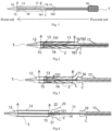
Fig. 1 is a schematic illustration of the structure of an implant delivery device according to a first embodiment of the present invention. -
Figs. 2 to 4 schematically illustrate loading and deploy operation of the implant delivery device according to the first embodiment of the present invention. -
Fig. 5 is a schematic illustration of the structure of an implant delivery device according to a second embodiment of the present invention. - In these
figures, 1 and 1' : an implant delivery device; 11, an inner tubular core; 12, a guide tip; 13, a sheath tube; 14, an inner tube; 15, an anchor; 151, a smaller-diameter member; 16, a transition member; 161, a transition section; 162, a catheter section; 17, a bending controllable tube; 18, a handle; 2, an implant; 21, an attachment lug; 22, an outflow portion; and 23, an inflow portion. - Specific embodiments of the present invention will be described in greater detail below with reference to the accompanying drawings. Features and advantages of the invention will be more readily apparent from the following detailed description, and from the appended claims. Note that the figures are provided in a very simplified form not necessarily presented to scale, with the only intention of facilitating convenience and clarity in explaining the disclosed embodiments.
- As used herein, the term "smooth connection" (detachable or not) refers to a connection of two components with a smooth continuation at their outer surfaces, which imparts high reliability to the whole structure (in particular of a catheter assembly) without causing damage to human tissues during use.
- As mentioned in the Background section, during the deployment of an implant, a sheath tube (which is a straight tube) used in conventional delivery devices is stiff and thus difficult to be retracted through a curved path, and forcible retraction may affect the bending control provided by a bending controllable tube and is detrimental to stable deployment of the prosthetic valve. Moreover, in the deployment process, it is very likely for the catheter to move forward or backward and thus displace the prosthetic mitral valve that has been partially deployed. This can become a cause for degraded deployment quality of the valve prosthesis. Further, when using a deployment method involving retrieval of the sheath tube and self-expansion of the implant, an outflow portion of the implant will be released prior to the release of an inflow portion of the implant. However, in practice, accurate positioning of the inflow portion against a target site is difficult and is often with positional deviations, which cannot be eliminated by adjustments even when identified.
- In view of the above, as shown in
Fig. 1 or5 , the present invention proposes adelivery device 1 for loading, delivering and deploying an implant. Thedelivery device 1 is composed of a catheter assembly and ahandle 18. Specifically, the catheter assembly includes an innertubular core 11, aguide tip 12, asheath tube 13, aninner tube 14, ananchor 15, atransition member 16 and a bendingcontrollable tube 17. - In addition, for convenience of description, as shown in
Fig. 1 , it is defined herein that any end facing toward the catheter assembly is a distal end and that facing toward thehandle 18 is a proximal end. In other words, any end located farther away from thehandle 18 is defined as a distal end and that closer to thehandle 18 as a proximal end. - As shown in
Figs. 1 to 2 , a proximal end of the innertubular core 11 is coupled to an inner tubular core actuation member arranged in thehandle 18 so that thehandle 18 is able to cause axial movement of the innertubular core 11, and the innertubular core 11 is fixed, at a distal end thereof, to theguide tip 12. Thesheath tube 13 has a distal end in smooth and fixed connection with a proximal end of theguide tip 12. That is, the outer surfaces at the connection where the distal end ofsheath tube 13 connects with the proximal end of theguide tip 12 are continuous and smooth. Thesheath tube 13 is sleeved over the innertubular core 11. - The
anchor 15 is fixed to theinner tube 14, and theinner tube 14 is disposed between the innertubular core 11 and thesheath tube 13. Theinner tube 14 is fixed, at a proximal end thereof, to an inner tube fastener in thehandle 18. In this way, theinner tube 14 is limited by thehandle 18 at six degrees of freedom (i.e., three translational degrees of freedom along the three orthogonal coordinate axes X, Y and Z and three rotational degrees of freedom about these three axes). - The
transition member 16 is a tubular structure sleeved over theinner tube 14 and preferably has a distal end that is nested within thesheath tube 13 in such a manner that the two components are partially fitted and thus sealed against each other. In some embodiments, the distal end of the transition member 16 (i.e., the part of thetransition member 16 nested within the sheath tube 13) has a maximum outer diameter that is slightly smaller than an inner diameter of thesheath tube 13, ensuring that thetransition member 16 is snugly received in thesheath tube 13 without any clearance therebetween. This means that the two components are fitted against each other where the maximum outer diameter of the distal end of thetransition member 16 is defined (i.e., the part of thetransition member 16 received within thesheath tube 13 is fitted against the sheath tube 13). A proximal end of thesheath tube 13 is smoothly and detachably coupled to thetransition member 16. That is, the outer surfaces at the connection where the proximal end of thesheath tube 13 connects with thetransition member 16 are smooth and continuous. In other embodiments hereof, the maximum outer diameter of thetransition member 16 at the distal end thereof may also be equal to the inner diameter of thesheath tube 13. In these cases, thetransition member 16 can also be nested in thesheath tube 13, so that they are fitted against each other where the maximum outer diameter of the distal end of thetransition member 16 is defined, thereby achieving a detachably coupling between thetransition member 16 and thesheath tube 13. In yet other embodiments hereof, the maximum outer diameter of thetransition member 16 at the distal end thereof may also be slightly greater than the inner diameter of thesheath tube 13. In these cases, the two components can also be connected together by an interference fit, thereby achieving a fitting at the maximum outer diameter of the distal end of thetransition member 16, thus a seal therebetween can be improved. More preferably, thesheath tube 13 andtransition member 16 are sealed against each other, and the proximal end of thesheath tube 13 is smoothly and detachably coupled to thetransition member 16. The bendingcontrollable tube 17 is adapted primarily to adjust an angle of deflection of the catheter assembly from an axial direction thereof. Thetransition member 16 may comprise at least two configurations, and the present invention illustrates two embodiments according to different configurations of thetransition member 16. - As shown in
Fig. 1 , adelivery device 1 according to this embodiment is composed of a catheter assembly and ahandle 18. Specifically, the catheter assembly includes an innertubular core 11, aguide tip 12, asheath tube 13, aninner tube 14, ananchor 15, atransition member 16 and a bendingcontrollable tube 17. - A proximal end of the inner
tubular core 11 is coupled to an inner tubular core actuation member arranged in thehandle 18 so that thehandle 18 is able to cause axial movement of the innertubular core 11, and the innertubular core 11 is fixed at a distal end thereof to theguide tip 12. Thesheath tube 13 has a distal end in a smooth and fixed connection with a proximal end of theguide tip 12 at position A. The sheath tube13 is sleeved over the innertubular core 11. In this way, the innertubular core 11 can be driven to cause axial movement of each of theguide tip 12 andsheath tube 13. - Optionally, the
guide tip 12 is streamlined in design and is preferably made of a polymer. Thesheath tube 13 is configured to press and retain animplant 2. The innertubular core 11 causes forth-and-back movement of the whole of theguide tip 12 andsheath 13, thereby achieving the loading and deployment of theimplant 2. Thesheath tube 13 may be formed of a metal, a polymer/metal composite material or the like. The innertubular core 11 may be fabricated from a polymer, a polymer/metal composite material, a metal or the like. - Optionally, as shown in
Fig. 1 , theguide tip 12 comprises a shape of conical, with the distal end of thesheath tube 13 being in a smooth and fixed connection with the proximal end (the end with a greater diameter) of theguide tip 12. Such a structural design enables reduced resistance to movement of thesheath tube 13 in the direction from the proximal to the distal end and enhanced stability in the implantation process. Of course, theguide tip 12 may comprise an alternative shape, such as a circular frustum or a hemisphere, and has at least one portion that is gradually decreased in outer diameter along the proximal to the distal end of theguide tip 12. - According to the present invention, the
handle 18 is not limited to any particular type and may be implemented as any one of a hand-driven handle, a power-driven handle or a hybrid hand- and power-driven handle. - As shown in
Fig. 1 , thesheath tube 13 has a proximal end in smooth and detachable connection with thetransition member 16 at position B. Thetransition member 16 is a tubular structure sleeved over theinner tube 14. In this embodiment, thetransition member 16 includes atransition section 161 and acatheter section 162, which communicate with each other and may be fabricated either separately from, or integrally with, each other. Thetransition member 16 may be fabricated from a polymer, a polymer/metal composite material, a metal or the like. - The
transition section 161 has a distal end, which is smoothly and detachably coupled (e.g., by static friction) to the proximal end of thesheath tube 13 at the position B, and a proximal end in smooth and fixed connection with a distal end of thecatheter section 162. Thetransition section 161 has at least one section gradually decreased in outer diameter along the direction from the distal to proximal end of thetransition section 161. For example, thetransition section 161 may be a hollow protrusion in the shape of a half cone, a hemisphere, a circular frustum or the like, which has a maximum outer diameter slightly smaller than an inner diameter of thesheath tube 13. Thesheath tube 13 may receive and wrap part of thetransition section 161, thus providing a smooth transition at the proximal end of thesheath tube 13 to a connecting portion of the bendingcontrollable tube 17, as described below. Thecatheter section 162 is a tubular structure sleeved over theinner tube 14 and has a proximal end coupled to a catheter actuation member arranged in thehandle 18, so that thehandle 18 is able to cause axial movement of thecatheter section 162. In this way, the movingcatheter section 162 can drive thetransition section 161 to move axially therewith. - The delivery device further comprises a bending
controllable tube 17. The bendingcontrollable tube 17 is sleeved over thecatheter section 162 and has an inner diameter greater than an outer diameter of thecatheter section 162. In this way, thecatheter section 162 is axially moveable within the bendingcontrollable tube 17. The bendingcontrollable tube 17 abuts, at a distal end thereof, against thetransition section 161. That is, as shown inFig. 1 , a proximal end of thetransition member 16 is brought into contact with, but is not fixedly connected to the bendingcontrollable tube 17 at position C. The bendingcontrollable tube 17 is coupled, at a proximal end thereof, to a bending controllable tube actuation member arranged in thehandle 18, so that thehandle 18 is able to cause axial movement of the bendingcontrollable tube 17. - The bending
controllable tube 17 includes a bending control mechanism for adjusting an angle of deflection of the bendingcontrollable tube 17 from an axial direction and hence of the entire catheter assembly from an axial direction. - The bending
controllable tube 17 may be a reinforced polymer tube, a reinforced metal tube or a tube consisting of modular metal sections, etc., with bending control capabilities. Specifically, the reinforced polymer tube may be a polymer tube embedded therein with one, two or more metal wires. By pulling the metal wires, bending control may be achieved and further by pulling different metal wires, bending control of different directions may be achieved. The reinforced metal tube may be a metal tube fabricated by braiding or cutting. The braiding may be spiral braiding or cross braiding, while the cutting may be accomplished by a laser to form cutouts. The metal tube fabricated by braiding or cutting may be embedded therein with one, two or more metal wires. By pulling the metal wires, bending control may be achieved and further by pulling different metal wires, bending control of different directions may be achieved. Further, a tube with modular metal sections is a tube consisting of multiple solid or hollow modular sections that are connected together in series. Such an active bending control design can facilitate to pass through more complicated bending contours in order to reach a target site. - As shown in
Fig. 1 , theanchor 15 is fixed to theinner tube 14 and is configured to secure theimplant 2. Theinner tube 14 is disposed between the innertubular core 11 and thesheath tube 13 and has a proximal end in fixed connection with an inner tube fastener arranged in thehandle 18. In this way, theinner tube 14 is limited by thehandle 18 at six degrees of freedom (i.e., three translational degrees of freedom along the axes X, Y and Z and three rotational degrees of freedom about axes X, Y and Z), in order to better support theimplant 2. Theinner tube 14 may be formed of a polymer, a polymer/metal composite material, a metal or the like. - Optionally, the
anchor 15 may be provided thereon with a plurality of grooves (not shown) for securing theimplant 2. Theanchor 15 may be formed of a metal or polymer. Preferably, as shown inFigs. 3 to 5 , theanchor 15 is connected, at a proximal end thereof, to a smaller-diameter member 151 made of a metal or polymer, which is also secured to theinner tube 14 to better support theimplant 2 by preventing theimplant 2 from twisting during loading and retrieval. - As shown in
Fig. 1 , the inner diameter of: the innertubular core 11, theinner tube 14, thecatheter section 162, the bendingcontrollable tube 17 and thesheath tube 13 increase sequentially. Preferably, the innertubular core 11, theinner tube 14, thecatheter section 162, the bendingcontrollable tube 17 and thesheath tube 13 are arranged coaxially. - Referring to
Figs. 2 to 4 , a method for implanting an implant using thedelivery device 1 as defined above according to an embodiment of the present invention may include the steps of: - S1: providing the
implant delivery device 1 and theimplant 2 to be loaded; - S2: causing the
sheath tube 13 to move toward distal end until exposing theanchor 15 by driving the innertubular core 11 through manipulating thehandle 18; attaching one end of theimplant 2 to theanchor 15; and causing thesheath tube 13 to move toward proximal end by driving the innertubular core 11 through manipulating thehandle 18, so that theimplant 2 is crimped and then is loaded into thesheath tube 13; - S3: driving the entire catheter assembly by an external force, thus causing the
sheath tube 13 and theanchor 15 to move toward distal end in synchronization therewith; and - S4: upon the
implant 2 being delivered to the target site, deploying theimplant 2 by causing thesheath tube 13 to move toward distal end through driving the innertubular core 11 by manipulating thehandle 18. - This process may involve loading, delivery and deployment. By driving a bearing through manipulating the
handle 18 in a power- or hand-driven manner, causing the inner tubular core actuation member to move forward and backward (i.e., the innertubular core 11 moves under the action of the inner tubular core actuation member). Further, driven by the innertubular core 11, the sheath tube13 and theguide tip 12 move axially with respect to theinner tube 14, thus achieving operations such as loading and deployment of theimplant 2. A more detailed description of this process is set forth below. - First of all, step S1 is carried out, in which the
implant delivery device 1 and theimplant 2 to be loaded are provided. In this embodiment, theimplant 2 may be implemented as a prosthetic mitral valve stent, which, as shown inFig. 4 , includes two attachment lugs 21, anoutflow portion 22 and aninflow portion 23, which are sequentially connected in this order, with theinflow portion 23 having a radius that is greater than a radius of theoutflow portion 22. It will be appreciated that the prosthetic mitral valve stent is merely an example of theimplant 2, and does not imply any limitation upon theimplant 2. Although geometric of a common prosthetic mitral valve stent are exemplified in this embodiment, the present invention is not limited to any particular geometric of any valve stent. - Subsequently, step S2 is performed, in which loading of the
implant 2 is accomplished by driving the innertubular core 11, through manipulating thehandle 18, to cause theguide tip 12 andsheath tube 13 to move toward the distal end as a whole, until the grooves on theanchor 15 are exposed, as shown inFig. 4 . The attachment lugs 21 of theimplant 2 are then snapped in the respective grooves so as to serve to facilitate stability of the stent during loading. Thehandle 18 is manipulated so that the innertubular core 11 is driven to move toward the proximal end, thus crimping theoutflow portion 22 of theimplant 2, as shown inFig. 3 . With continued movement of thesheath tube 13, theinflow portion 23 of theimplant 2 is also crimped. In this way, theentire implant 2 is wrapped by thesheath tube 13, with its distal end abutting against an end face of theguide tip 12. At this point, loading of theimplant 2 is achieved, as shown inFig. 2 - Afterwards, step S3 is performed in which delivery of the
implant 2 is accomplished by exerting an external force to introduce the catheter assembly in thedelivery device 1 over a guide wire into the body of a patient via a puncture. The catheter assembly is then advanced as a whole through the femoral vein and across the interatrial septum. In this way, thesheath tube 13 and theanchor 15 are delivered in synchronization to distal end, until to the target site (i.e., the site of the lesion). - Finally, step S4 is performed in which deployment of the
implant 2 is accomplished by adjusting an angle of deflection of the sheath tube 13 (the adjustment is achieved by tuning the bendingcontrollable tube 17 and is followed by fixing the bendingcontrollable tube 17 in place) after it has reached the target site, which results in coaxiality with the native mitral annulus. A "Forward" button on thehandle 18 is then pressed, causing theguide tip 12 and thesheath tube 13 to move toward distal end, which results in beginning of deployment of theimplant 2. This is continued until theimplant 2 is completely deployed to the target site and detached from the catheter assembly, as shown inFigs. 2 to 4 . - Specifically, during movement of the
sheath 13 toward the distal end, theinflow portion 23 of theimplant 2 is first released, followed by the release of theoutflow portion 22 of theimplant 2 under the effect of further movement of thesheath tube 13, until the proximal end of thesheath tube 13 reaches theanchor 15 and the grooves on theanchor 15 are exposed. At this point, complete deployment of theimplant 2 is achieved. - In addition, after the completion of the implantation of the
implant 2, it is necessary to retrieve the catheter assembly in theimplant delivery device 1. The retrieval can be accomplished by causing thecatheter section 162 of thetransition member 16 and hence thetransition section 161 thereof to move toward the distal end so that thetransition section 161 of thetransition member 16 reaches a position in relation to thesheath tube 13 as shown inFig. 1 , where they are coupled together smoothly and detachably. Thehandle 18 is then manipulated to retrieve the catheter assembly from the patient's body. - In the
implant delivery device 1 according to this embodiment of the present invention, thesheath tube 13 is fixed to theguide tip 12, and the innertubular core 11 is provided. In the loading process, the innertubular core 11 drives both thesheath tube 13 and theguide tip 12 to move toward distal end until theanchor 15 is exposed. After the attachment lugs 21 of theimplant 2 are attached to theanchor 15, the innertubular core 11 is controlled to drive thesheath tube 13 and theguide tip 12 to move toward proximal end to crimp theimplant 2, until accomplishing the loading of theimplant 2. In the deployment process, the innertubular core 11 causes thesheath tube 13 and theguide tip 12 to move toward distal end, which allows release of the implant'sinflow portion 23 and then of itsoutflow portion 22. In this way, it is unnecessary to retract thesheath tube 13 during deployment of theimplant 2, dispensing with its need to travel through a three-dimensionally curved path. This can effectively avoid the problems that may arise from retraction of thesheath tube 13 through a three-dimensionally curved path, such as unstable or faulty deployment of theimplant 2. In practice, since theimplant 2 is structured as having a radius greater in the inflow portion than in the outflow portion, when theoutflow portion 22 is released, it will interfere with leaflets of theimplant 2. As a result, it will be different to remedy any found unsatisfactory positioning of the implant by adjustment. In contrast, according to the present invention, since thesheath tube 13 employs a distal end deployment design, theinflow portion 23 of theimplant 2 will be released prior to the release of theoutflow portion 22. In this way, once theinflow portion 23 is released, a check against the target site is allowed, and the implant can be adjusted in a timely manner as soon as it is found that inaccurate positioning would take place. Therefore, the delivery device according to the present invention enables accurate deployment of theimplant 2 to the site of the lesion with ensured high quality. - Furthermore, the
transition member 16 included in the implant delivery device according to this embodiment of the present invention can prevent theimplant 2 from partially interfering with thesheath tube 13 seriously during the retrieval of the implant delivery device, which may cause damage to theimplant 2. - The
transition member 16 ofEmbodiment 1 is complicated in structure because it includes thetransition section 161 andcatheter section 162, in communication with each other. Such structural complexity will also complicate the implantation of theimplant 2. In view of this, as shown inFig. 5 , an implant delivery device 1' according toEmbodiment 2 includes a modifiedtransition member 16. - As shown in
Fig. 5 , according toEmbodiment 2, thetransition member 16 includes only atransition section 161 without acatheter section 162. In this case, thetransition section 161 is directly coupled, at a proximal end thereof, to the distal end of the bendingcontrollable tube 17 by a smooth and fixed connection, and the axial movement of thetransition section 161 is controlled by axial movement of the bendingcontrollable tube 17. Other components of the implant delivery device 1' according toEmbodiment 2 are the same as those ofEmbodiment 1, and a further description thereof is deemed unnecessary. Further, a method for implanting an implant by this implant delivery device 1' is the same as that ofEmbodiment 1, and a further description thereof is omitted here. - After the completion of the implantation of the
implant 2, it is necessary to retrieve the catheter assembly in the implant delivery device 1'. First of all, the bending control mechanism of the bendingcontrollable tube 17 is unlocked, and thehandle 18 is manipulated to drive the bendingcontrollable tube 17 to cause thetransition section 161 move to distal end. As a result, thetransition section 161 and thesheath tube 13 are at positions relative to each other, as shown inFig. 5 , where they are smoothly connected together. The catheter assembly is then retrieved from the patient's body by manipulating thehandle 18. - In summary, in the implant delivery device according to embodiments of the present invention, the distal end of the sheath tube is fixed to the guide tip, and the implant is loaded at the proximal end of the sheath tube. During deployment of the implant, the sheath tube is caused to move to distal end, that is, the sheath tube continues moving toward the target site of the implant, rather than moves backward to the handle. This can effectively avoid the problems that may arise from retraction of the sheath tube through a three-dimensionally curved path, such as unstable or even faulty deployment of the implant. Moreover, in view of the fact that the implant is structured as having a radius greater in the inflow portion than in the outflow portion, it is designed that the inflow portion of the implant is released prior to the release of the outflow portion thereof. Once the inflow portion of the implant is deployed, a check against the target site may be performed, and the implant can be adjusted in a timely manner as soon as it is found that inaccurate positioning would take place. This enables more accurate deployment of the implant with enhanced quality. Further, the transition member arranged at the proximal end of the sheath tube can prevent the implant from partially interfering with the sheath tube seriously during the retrieval of the delivery device, which may cause damage to the implant.
Claims (9)
- A delivery device (1,1') for loading, delivering and deploying an implant, wherein the delivery device (1,1') comprises a handle (18), an inner tubular core (11), a sheath tube (13), a guide tip (12), an inner tube (14), an anchor (15), a transition member (16), and a bending controllable tube (17), wherein the inner tubular core (11) is coupled, at a proximal end thereof, to an inner tubular core actuation member arranged in the handle (18), wherein the guide tip (12) is disposed at a distal end of the inner tubular core (11) and fixedly connected to a distal end of the sheath tube (13), and wherein the sheath tube (13) is configured to press and retain the implant, and is sleeved over the inner tubular core (11);wherein the inner tube (14) is disposed between the inner tubular core (11) and the sheath tube (13), and the inner tube (14) is fixed, at a proximal end thereof, to an inner tube fastener arranged in the handle (18);wherein the anchor (15) is in fixed connection with a distal end of the inner tube (14) and is configured to retain the implant;wherein the transition member (16) is configured as a tubular structure sleeved over the inner tube (14); the transition member (16) is disposed within the sheath tube (13); and the transition member (16) and the sheath tube (13) are partially fitted against each other;wherein the transition member (16) comprises a transition section (161), wherein the transition section (161) is configured as a hollow protrusion, and the transition section (161) is smoothly and detachably coupled, at a distal end thereof, to the proximal end of the sheath tube (13);wherein the bending controllable tube (17) is fixed, at a distal end thereof, to a proximal end of the transition section (161); the bending controllable tube (17) is coupled, at a proximal end thereof, to a bending controllable tube actuation member arranged in the handle (18); and the bending controllable tube (17) comprises a bending control mechanism adapted to adjust an angle of deflection from an axial direction of the bending controllable tube (17).
- The delivery device (1,1') of claim 1, wherein the guide tip (12) has a conical shape, and wherein the distal end of the sheath tube (13) is in smooth and fixed connection with a proximal end of the guide tip (12).
- The delivery device (1,1') of claim 1, wherein the sheath tube (13) is smoothly and detachably coupled, at a proximal end thereof, to the transition member (16) by static friction.
- The delivery device (1,1') of claim 1, wherein the transition member (16) further comprises a catheter section (162) in communication with the transition section (161), the transition section (161) having a proximal end in smooth and fixed connection with a distal end of the catheter section (162).
- The delivery device (1,1') of claim 4, wherein the bending controllable tube (17) is sleeved over the catheter section (162).
- The delivery device (1,1') of claim 1, wherein the bending controllable tube (17) is sleeved over the inner tube (14).
- The delivery device (1,1') of claim 4, wherein the protrusion comprises: a half-cone structure, a hemisphere structure or a circular frustum structure.
- The delivery device (1,1') of claim 4, wherein at least a portion of the transition section (161) has a gradually decreased outer diameter in a direction from the distal end to the proximal end of the transition section (161).
- The delivery device (1,1') of claim 1, wherein the anchor (15) has a plurality of grooves provided thereon.
Applications Claiming Priority (2)
| Application Number | Priority Date | Filing Date | Title |
|---|---|---|---|
| CN201811014867.7A CN110870811B (en) | 2018-08-31 | 2018-08-31 | Conveying device |
| PCT/CN2019/103838 WO2020043204A1 (en) | 2018-08-31 | 2019-08-30 | Delivery device |
Publications (3)
| Publication Number | Publication Date |
|---|---|
| EP3845203A1 EP3845203A1 (en) | 2021-07-07 |
| EP3845203A4 EP3845203A4 (en) | 2021-11-03 |
| EP3845203B1 true EP3845203B1 (en) | 2024-12-18 |
Family
ID=69642705
Family Applications (1)
| Application Number | Title | Priority Date | Filing Date |
|---|---|---|---|
| EP19853341.6A Active EP3845203B1 (en) | 2018-08-31 | 2019-08-30 | Delivery device |
Country Status (6)
| Country | Link |
|---|---|
| US (1) | US12403006B2 (en) |
| EP (1) | EP3845203B1 (en) |
| JP (1) | JP7473530B2 (en) |
| KR (1) | KR102563497B1 (en) |
| CN (1) | CN110870811B (en) |
| WO (1) | WO2020043204A1 (en) |
Families Citing this family (10)
| Publication number | Priority date | Publication date | Assignee | Title |
|---|---|---|---|---|
| CN111671520B (en) * | 2020-06-12 | 2025-07-22 | 绍兴梅奥心磁医疗科技有限公司 | Sheath driving device of adaptive catheter mechanical arm |
| CN116115401B (en) * | 2021-11-15 | 2025-09-02 | 先健科技(深圳)有限公司 | Conveyors and conveying systems |
| CN116115400B (en) * | 2021-11-15 | 2025-09-02 | 先健科技(深圳)有限公司 | Conveying devices and conveying systems |
| CN116407329A (en) * | 2021-12-30 | 2023-07-11 | 先健科技(深圳)有限公司 | Sheath-core assembly, manufacturing method of sheath-core assembly, and conveyor |
| CN114404108B (en) * | 2022-01-25 | 2025-09-12 | 北京领健医疗科技有限公司 | Sheath bending handle, delivery device and valve repair system |
| CN114376650B (en) * | 2022-01-26 | 2026-02-06 | 上海申淇医疗科技有限公司 | Conveying device for spring rings |
| CN115886881A (en) * | 2022-11-17 | 2023-04-04 | 西安华峰医疗科技有限公司 | Imaging catheter with adjustable bend radius |
| CN116269651B (en) * | 2022-12-06 | 2023-10-10 | 杭州亿科医疗科技有限公司 | Prevent that thrombus extraction net from releasing in advance's thrombus extraction device |
| CN115844593A (en) * | 2022-12-30 | 2023-03-28 | 鑫依医疗科技(北京)有限公司 | Adjustable curved transcatheter valve delivery system with accurate positioning function |
| CN120093493B (en) * | 2023-12-05 | 2026-03-17 | 深圳佰特微医疗科技有限公司 | An implant delivery system |
Family Cites Families (39)
| Publication number | Priority date | Publication date | Assignee | Title |
|---|---|---|---|---|
| US5415664A (en) * | 1994-03-30 | 1995-05-16 | Corvita Corporation | Method and apparatus for introducing a stent or a stent-graft |
| US6425916B1 (en) * | 1999-02-10 | 2002-07-30 | Michi E. Garrison | Methods and devices for implanting cardiac valves |
| US6454799B1 (en) | 2000-04-06 | 2002-09-24 | Edwards Lifesciences Corporation | Minimally-invasive heart valves and methods of use |
| US6582460B1 (en) * | 2000-11-20 | 2003-06-24 | Advanced Cardiovascular Systems, Inc. | System and method for accurately deploying a stent |
| US7556646B2 (en) | 2001-09-13 | 2009-07-07 | Edwards Lifesciences Corporation | Methods and apparatuses for deploying minimally-invasive heart valves |
| EP2422751A3 (en) * | 2004-05-05 | 2013-01-02 | Direct Flow Medical, Inc. | Unstented heart valve with formed in place support structure |
| US7402151B2 (en) * | 2004-12-17 | 2008-07-22 | Biocardia, Inc. | Steerable guide catheters and methods for their use |
| US8167932B2 (en) * | 2005-10-18 | 2012-05-01 | Edwards Lifesciences Corporation | Heart valve delivery system with valve catheter |
| US20070213813A1 (en) | 2005-12-22 | 2007-09-13 | Symetis Sa | Stent-valves for valve replacement and associated methods and systems for surgery |
| US8070799B2 (en) * | 2006-12-19 | 2011-12-06 | Sorin Biomedica Cardio S.R.L. | Instrument and method for in situ deployment of cardiac valve prostheses |
| US9138315B2 (en) * | 2007-04-13 | 2015-09-22 | Jenavalve Technology Gmbh | Medical device for treating a heart valve insufficiency or stenosis |
| US8114154B2 (en) * | 2007-09-07 | 2012-02-14 | Sorin Biomedica Cardio S.R.L. | Fluid-filled delivery system for in situ deployment of cardiac valve prostheses |
| AU2009205739B2 (en) * | 2008-01-16 | 2014-09-25 | St. Jude Medical, Inc. | Delivery and retrieval systems for collapsible/expandable prosthetic heart valves |
| CA2739275C (en) * | 2008-10-01 | 2017-01-17 | Impala, Inc. | Delivery system for vascular implant |
| US8986361B2 (en) * | 2008-10-17 | 2015-03-24 | Medtronic Corevalve, Inc. | Delivery system for deployment of medical devices |
| US8372133B2 (en) * | 2009-10-05 | 2013-02-12 | 480 Biomedical, Inc. | Polymeric implant delivery system |
| US8475523B2 (en) * | 2010-02-17 | 2013-07-02 | Medtronic, Inc. | Distal tip assembly for a heart valve delivery catheter |
| US9023095B2 (en) * | 2010-05-27 | 2015-05-05 | Idev Technologies, Inc. | Stent delivery system with pusher assembly |
| US9301864B2 (en) * | 2010-06-08 | 2016-04-05 | Veniti, Inc. | Bi-directional stent delivery system |
| US10130470B2 (en) * | 2010-08-17 | 2018-11-20 | St. Jude Medical, Llc | Sleeve for facilitating movement of a transfemoral catheter |
| ES2651744T3 (en) * | 2010-09-20 | 2018-01-29 | St. Jude Medical, Cardiology Division, Inc. | Delivery device provided with a curved rod and a straightening member for transcatheter implantation of an aortic valve |
| EP3111889B1 (en) | 2010-09-24 | 2019-11-13 | Symetis SA | A transcatheter aortic valve implantation system |
| CN102525698A (en) * | 2010-12-31 | 2012-07-04 | 微创医疗器械(上海)有限公司 | Interposed medical appliance delivery and release device |
| US8893370B2 (en) * | 2011-07-28 | 2014-11-25 | St. Jude Medical, Cardiology Division, Inc. | System for loading a collapsible heart valve |
| WO2013056898A1 (en) * | 2011-10-21 | 2013-04-25 | Jenavalve Technology Inc. | Catheter system for introducing an expandable heart valve stent into the body of a patient, insertion system with a catheter system and medical device for treatment of a heart valve defect |
| US9456912B2 (en) * | 2011-10-31 | 2016-10-04 | Merit Medical Systems, Inc. | Implantable device deployment apparatus |
| US9579198B2 (en) * | 2012-03-01 | 2017-02-28 | Twelve, Inc. | Hydraulic delivery systems for prosthetic heart valve devices and associated methods |
| EP2908784B1 (en) | 2012-10-17 | 2017-07-12 | Angiomed GmbH & Co. Medizintechnik KG | Hand unit to release a self-expanding implant |
| CN203539840U (en) * | 2013-09-04 | 2014-04-16 | 杭州启明医疗器械有限公司 | Adjustable bending sheath canal and conveying system with same |
| US10149758B2 (en) * | 2014-04-01 | 2018-12-11 | Medtronic, Inc. | System and method of stepped deployment of prosthetic heart valve |
| CR20170245A (en) * | 2014-12-05 | 2017-09-14 | Edwards Lifesciences Corp | DIRIGIBLE CATETER WITH TRACTION CABLE |
| DE202016008737U1 (en) | 2015-12-15 | 2019-04-05 | Neovasc Tiara Inc. | Transseptal delivery system |
| EP3454794B1 (en) * | 2016-05-13 | 2021-04-14 | St. Jude Medical, Cardiology Division, Inc. | Systems for device implantation |
| CN109789017B (en) * | 2016-08-19 | 2022-05-31 | 爱德华兹生命科学公司 | Steerable delivery system for replacing a mitral valve and methods of use |
| EP3532159B1 (en) * | 2016-10-27 | 2021-12-22 | Cardiac Pacemakers, Inc. | Implantable medical device delivery system with integrated sensor |
| CN108245290B (en) * | 2016-12-29 | 2024-05-31 | 先健科技(深圳)有限公司 | Conveyor system |
| CN107496055B (en) | 2017-08-10 | 2021-06-08 | 上海微创心通医疗科技有限公司 | Heart valve delivery catheter and delivery system |
| CN108245293B (en) * | 2018-01-22 | 2024-03-19 | 苏州恒瑞宏远医疗科技有限公司 | Long-specification vascular stent conveying system |
| CN209678757U (en) * | 2018-08-31 | 2019-11-26 | 上海微创心通医疗科技有限公司 | Conveying device |
-
2018
- 2018-08-31 CN CN201811014867.7A patent/CN110870811B/en active Active
-
2019
- 2019-08-30 KR KR1020217002959A patent/KR102563497B1/en active Active
- 2019-08-30 US US17/257,139 patent/US12403006B2/en active Active
- 2019-08-30 EP EP19853341.6A patent/EP3845203B1/en active Active
- 2019-08-30 JP JP2021505267A patent/JP7473530B2/en active Active
- 2019-08-30 WO PCT/CN2019/103838 patent/WO2020043204A1/en not_active Ceased
Also Published As
| Publication number | Publication date |
|---|---|
| US12403006B2 (en) | 2025-09-02 |
| CN110870811A (en) | 2020-03-10 |
| CN110870811B (en) | 2025-06-17 |
| WO2020043204A1 (en) | 2020-03-05 |
| US20210154007A1 (en) | 2021-05-27 |
| EP3845203A1 (en) | 2021-07-07 |
| KR20210024159A (en) | 2021-03-04 |
| EP3845203A4 (en) | 2021-11-03 |
| KR102563497B1 (en) | 2023-08-04 |
| JP7473530B2 (en) | 2024-04-23 |
| JP2021533852A (en) | 2021-12-09 |
Similar Documents
| Publication | Publication Date | Title |
|---|---|---|
| US12403006B2 (en) | Delivery device | |
| JP7198838B2 (en) | Implant delivery fittings and implant delivery systems | |
| US11712337B2 (en) | Delivery systems and methods of implantation for prosthetic heart valves | |
| US10213300B2 (en) | Hypotube shaft with articulation mechanism | |
| US20210052382A1 (en) | Heart valve delivery catheter with safety button | |
| EP2538883B1 (en) | Catheter assembly with valve crimping accessories | |
| US8475523B2 (en) | Distal tip assembly for a heart valve delivery catheter | |
| US20140005770A1 (en) | Catheter Assembly With Valve Crimping Accessories | |
| EP4183371A1 (en) | Heart valve prosthesis delivery system and method for delivery of heart valve prosthesis with introducer sheath and loading system | |
| EP2919712A1 (en) | Valve prosthesis deployment assembly and method | |
| US20240024110A1 (en) | Delivery systems for implants | |
| CN209678757U (en) | Conveying device | |
| US20250387225A1 (en) | Prosthetic medical device delivery apparatus | |
| HK40088535B (en) | Steerable delivery apparatus for an implantable medical device |
Legal Events
| Date | Code | Title | Description |
|---|---|---|---|
| STAA | Information on the status of an ep patent application or granted ep patent |
Free format text: STATUS: THE INTERNATIONAL PUBLICATION HAS BEEN MADE |
|
| STAA | Information on the status of an ep patent application or granted ep patent |
Free format text: STATUS: REQUEST FOR EXAMINATION WAS MADE |
|
| PUAI | Public reference made under article 153(3) epc to a published international application that has entered the european phase |
Free format text: ORIGINAL CODE: 0009012 |
|
| 17P | Request for examination filed |
Effective date: 20201223 |
|
| AK | Designated contracting states |
Kind code of ref document: A1 Designated state(s): AL AT BE BG CH CY CZ DE DK EE ES FI FR GB GR HR HU IE IS IT LI LT LU LV MC MK MT NL NO PL PT RO RS SE SI SK SM TR |
|
| A4 | Supplementary search report drawn up and despatched |
Effective date: 20211006 |
|
| RIC1 | Information provided on ipc code assigned before grant |
Ipc: A61F 2/95 20130101ALI20210930BHEP Ipc: A61F 2/02 20060101ALI20210930BHEP Ipc: A61F 2/24 20060101AFI20210930BHEP |
|
| DAV | Request for validation of the european patent (deleted) | ||
| DAX | Request for extension of the european patent (deleted) | ||
| GRAP | Despatch of communication of intention to grant a patent |
Free format text: ORIGINAL CODE: EPIDOSNIGR1 |
|
| STAA | Information on the status of an ep patent application or granted ep patent |
Free format text: STATUS: GRANT OF PATENT IS INTENDED |
|
| INTG | Intention to grant announced |
Effective date: 20240913 |
|
| GRAS | Grant fee paid |
Free format text: ORIGINAL CODE: EPIDOSNIGR3 |
|
| GRAA | (expected) grant |
Free format text: ORIGINAL CODE: 0009210 |
|
| STAA | Information on the status of an ep patent application or granted ep patent |
Free format text: STATUS: THE PATENT HAS BEEN GRANTED |
|
| AK | Designated contracting states |
Kind code of ref document: B1 Designated state(s): AL AT BE BG CH CY CZ DE DK EE ES FI FR GB GR HR HU IE IS IT LI LT LU LV MC MK MT NL NO PL PT RO RS SE SI SK SM TR |
|
| REG | Reference to a national code |
Ref country code: CH Ref legal event code: EP |
|
| REG | Reference to a national code |
Ref country code: DE Ref legal event code: R096 Ref document number: 602019063772 Country of ref document: DE |
|
| REG | Reference to a national code |
Ref country code: IE Ref legal event code: FG4D |
|
| REG | Reference to a national code |
Ref country code: LT Ref legal event code: MG9D |
|
| PG25 | Lapsed in a contracting state [announced via postgrant information from national office to epo] |
Ref country code: HR Free format text: LAPSE BECAUSE OF FAILURE TO SUBMIT A TRANSLATION OF THE DESCRIPTION OR TO PAY THE FEE WITHIN THE PRESCRIBED TIME-LIMIT Effective date: 20241218 |
|
| PG25 | Lapsed in a contracting state [announced via postgrant information from national office to epo] |
Ref country code: FI Free format text: LAPSE BECAUSE OF FAILURE TO SUBMIT A TRANSLATION OF THE DESCRIPTION OR TO PAY THE FEE WITHIN THE PRESCRIBED TIME-LIMIT Effective date: 20241218 |
|
| PG25 | Lapsed in a contracting state [announced via postgrant information from national office to epo] |
Ref country code: BG Free format text: LAPSE BECAUSE OF FAILURE TO SUBMIT A TRANSLATION OF THE DESCRIPTION OR TO PAY THE FEE WITHIN THE PRESCRIBED TIME-LIMIT Effective date: 20241218 |
|
| PG25 | Lapsed in a contracting state [announced via postgrant information from national office to epo] |
Ref country code: NO Free format text: LAPSE BECAUSE OF FAILURE TO SUBMIT A TRANSLATION OF THE DESCRIPTION OR TO PAY THE FEE WITHIN THE PRESCRIBED TIME-LIMIT Effective date: 20250318 |
|
| REG | Reference to a national code |
Ref country code: NL Ref legal event code: MP Effective date: 20241218 |
|
| PG25 | Lapsed in a contracting state [announced via postgrant information from national office to epo] |
Ref country code: LV Free format text: LAPSE BECAUSE OF FAILURE TO SUBMIT A TRANSLATION OF THE DESCRIPTION OR TO PAY THE FEE WITHIN THE PRESCRIBED TIME-LIMIT Effective date: 20241218 Ref country code: GR Free format text: LAPSE BECAUSE OF FAILURE TO SUBMIT A TRANSLATION OF THE DESCRIPTION OR TO PAY THE FEE WITHIN THE PRESCRIBED TIME-LIMIT Effective date: 20250319 |
|
| PG25 | Lapsed in a contracting state [announced via postgrant information from national office to epo] |
Ref country code: RS Free format text: LAPSE BECAUSE OF FAILURE TO SUBMIT A TRANSLATION OF THE DESCRIPTION OR TO PAY THE FEE WITHIN THE PRESCRIBED TIME-LIMIT Effective date: 20250318 |
|
| PG25 | Lapsed in a contracting state [announced via postgrant information from national office to epo] |
Ref country code: NL Free format text: LAPSE BECAUSE OF FAILURE TO SUBMIT A TRANSLATION OF THE DESCRIPTION OR TO PAY THE FEE WITHIN THE PRESCRIBED TIME-LIMIT Effective date: 20241218 |
|
| REG | Reference to a national code |
Ref country code: AT Ref legal event code: MK05 Ref document number: 1751621 Country of ref document: AT Kind code of ref document: T Effective date: 20241218 |
|
| PG25 | Lapsed in a contracting state [announced via postgrant information from national office to epo] |
Ref country code: SM Free format text: LAPSE BECAUSE OF FAILURE TO SUBMIT A TRANSLATION OF THE DESCRIPTION OR TO PAY THE FEE WITHIN THE PRESCRIBED TIME-LIMIT Effective date: 20241218 |
|
| PG25 | Lapsed in a contracting state [announced via postgrant information from national office to epo] |
Ref country code: PL Free format text: LAPSE BECAUSE OF FAILURE TO SUBMIT A TRANSLATION OF THE DESCRIPTION OR TO PAY THE FEE WITHIN THE PRESCRIBED TIME-LIMIT Effective date: 20241218 |
|
| PG25 | Lapsed in a contracting state [announced via postgrant information from national office to epo] |
Ref country code: ES Free format text: LAPSE BECAUSE OF FAILURE TO SUBMIT A TRANSLATION OF THE DESCRIPTION OR TO PAY THE FEE WITHIN THE PRESCRIBED TIME-LIMIT Effective date: 20241218 |
|
| PG25 | Lapsed in a contracting state [announced via postgrant information from national office to epo] |
Ref country code: IS Free format text: LAPSE BECAUSE OF FAILURE TO SUBMIT A TRANSLATION OF THE DESCRIPTION OR TO PAY THE FEE WITHIN THE PRESCRIBED TIME-LIMIT Effective date: 20250418 |
|
| PG25 | Lapsed in a contracting state [announced via postgrant information from national office to epo] |
Ref country code: PT Free format text: LAPSE BECAUSE OF FAILURE TO SUBMIT A TRANSLATION OF THE DESCRIPTION OR TO PAY THE FEE WITHIN THE PRESCRIBED TIME-LIMIT Effective date: 20250421 |
|
| PG25 | Lapsed in a contracting state [announced via postgrant information from national office to epo] |
Ref country code: EE Free format text: LAPSE BECAUSE OF FAILURE TO SUBMIT A TRANSLATION OF THE DESCRIPTION OR TO PAY THE FEE WITHIN THE PRESCRIBED TIME-LIMIT Effective date: 20241218 |
|
| PG25 | Lapsed in a contracting state [announced via postgrant information from national office to epo] |
Ref country code: RO Free format text: LAPSE BECAUSE OF FAILURE TO SUBMIT A TRANSLATION OF THE DESCRIPTION OR TO PAY THE FEE WITHIN THE PRESCRIBED TIME-LIMIT Effective date: 20241218 Ref country code: AT Free format text: LAPSE BECAUSE OF FAILURE TO SUBMIT A TRANSLATION OF THE DESCRIPTION OR TO PAY THE FEE WITHIN THE PRESCRIBED TIME-LIMIT Effective date: 20241218 |
|
| PG25 | Lapsed in a contracting state [announced via postgrant information from national office to epo] |
Ref country code: SK Free format text: LAPSE BECAUSE OF FAILURE TO SUBMIT A TRANSLATION OF THE DESCRIPTION OR TO PAY THE FEE WITHIN THE PRESCRIBED TIME-LIMIT Effective date: 20241218 |
|
| PG25 | Lapsed in a contracting state [announced via postgrant information from national office to epo] |
Ref country code: CZ Free format text: LAPSE BECAUSE OF FAILURE TO SUBMIT A TRANSLATION OF THE DESCRIPTION OR TO PAY THE FEE WITHIN THE PRESCRIBED TIME-LIMIT Effective date: 20241218 |
|
| PG25 | Lapsed in a contracting state [announced via postgrant information from national office to epo] |
Ref country code: IT Free format text: LAPSE BECAUSE OF FAILURE TO SUBMIT A TRANSLATION OF THE DESCRIPTION OR TO PAY THE FEE WITHIN THE PRESCRIBED TIME-LIMIT Effective date: 20241218 |
|
| PG25 | Lapsed in a contracting state [announced via postgrant information from national office to epo] |
Ref country code: SE Free format text: LAPSE BECAUSE OF FAILURE TO SUBMIT A TRANSLATION OF THE DESCRIPTION OR TO PAY THE FEE WITHIN THE PRESCRIBED TIME-LIMIT Effective date: 20241218 |
|
| REG | Reference to a national code |
Ref country code: DE Ref legal event code: R097 Ref document number: 602019063772 Country of ref document: DE |
|
| PG25 | Lapsed in a contracting state [announced via postgrant information from national office to epo] |
Ref country code: DK Free format text: LAPSE BECAUSE OF FAILURE TO SUBMIT A TRANSLATION OF THE DESCRIPTION OR TO PAY THE FEE WITHIN THE PRESCRIBED TIME-LIMIT Effective date: 20241218 |
|
| PGFP | Annual fee paid to national office [announced via postgrant information from national office to epo] |
Ref country code: DE Payment date: 20250820 Year of fee payment: 7 |
|
| PGFP | Annual fee paid to national office [announced via postgrant information from national office to epo] |
Ref country code: FR Payment date: 20250828 Year of fee payment: 7 |
|
| PLBE | No opposition filed within time limit |
Free format text: ORIGINAL CODE: 0009261 |
|
| STAA | Information on the status of an ep patent application or granted ep patent |
Free format text: STATUS: NO OPPOSITION FILED WITHIN TIME LIMIT |
|
| REG | Reference to a national code |
Ref country code: CH Ref legal event code: L10 Free format text: ST27 STATUS EVENT CODE: U-0-0-L10-L00 (AS PROVIDED BY THE NATIONAL OFFICE) Effective date: 20251029 |
|
| 26N | No opposition filed |
Effective date: 20250919 |
|
| REG | Reference to a national code |
Ref country code: CH Ref legal event code: H13 Free format text: ST27 STATUS EVENT CODE: U-0-0-H10-H13 (AS PROVIDED BY THE NATIONAL OFFICE) Effective date: 20260324 |
|
| PG25 | Lapsed in a contracting state [announced via postgrant information from national office to epo] |
Ref country code: MC Free format text: LAPSE BECAUSE OF FAILURE TO SUBMIT A TRANSLATION OF THE DESCRIPTION OR TO PAY THE FEE WITHIN THE PRESCRIBED TIME-LIMIT Effective date: 20241218 |
|
| PG25 | Lapsed in a contracting state [announced via postgrant information from national office to epo] |
Ref country code: LU Free format text: LAPSE BECAUSE OF NON-PAYMENT OF DUE FEES Effective date: 20250830 |
|
| PG25 | Lapsed in a contracting state [announced via postgrant information from national office to epo] |
Ref country code: CH Free format text: LAPSE BECAUSE OF NON-PAYMENT OF DUE FEES Effective date: 20250831 |
|
| GBPC | Gb: european patent ceased through non-payment of renewal fee |
Effective date: 20250830 |