EP3845177A1 - Multi-purpose sensing and radiofrequency (rf) ablation spiral electrode for catheter - Google Patents
Multi-purpose sensing and radiofrequency (rf) ablation spiral electrode for catheter Download PDFInfo
- Publication number
- EP3845177A1 EP3845177A1 EP20217531.1A EP20217531A EP3845177A1 EP 3845177 A1 EP3845177 A1 EP 3845177A1 EP 20217531 A EP20217531 A EP 20217531A EP 3845177 A1 EP3845177 A1 EP 3845177A1
- Authority
- EP
- European Patent Office
- Prior art keywords
- electrode
- spiral
- spiral electrode
- distal end
- ablation
- Prior art date
- Legal status (The legal status is an assumption and is not a legal conclusion. Google has not performed a legal analysis and makes no representation as to the accuracy of the status listed.)
- Granted
Links
Images
Classifications
-
- A—HUMAN NECESSITIES
- A61—MEDICAL OR VETERINARY SCIENCE; HYGIENE
- A61B—DIAGNOSIS; SURGERY; IDENTIFICATION
- A61B18/00—Surgical instruments, devices or methods for transferring non-mechanical forms of energy to or from the body
- A61B18/04—Surgical instruments, devices or methods for transferring non-mechanical forms of energy to or from the body by heating
- A61B18/12—Surgical instruments, devices or methods for transferring non-mechanical forms of energy to or from the body by heating by passing a current through the tissue to be heated, e.g. high-frequency current
-
- A—HUMAN NECESSITIES
- A61—MEDICAL OR VETERINARY SCIENCE; HYGIENE
- A61B—DIAGNOSIS; SURGERY; IDENTIFICATION
- A61B18/00—Surgical instruments, devices or methods for transferring non-mechanical forms of energy to or from the body
- A61B18/04—Surgical instruments, devices or methods for transferring non-mechanical forms of energy to or from the body by heating
- A61B18/12—Surgical instruments, devices or methods for transferring non-mechanical forms of energy to or from the body by heating by passing a current through the tissue to be heated, e.g. high-frequency current
- A61B18/14—Probes or electrodes therefor
- A61B18/1492—Probes or electrodes therefor having a flexible, catheter-like structure, e.g. for heart ablation
-
- A—HUMAN NECESSITIES
- A61—MEDICAL OR VETERINARY SCIENCE; HYGIENE
- A61B—DIAGNOSIS; SURGERY; IDENTIFICATION
- A61B34/00—Computer-aided surgery; Manipulators or robots specially adapted for use in surgery
- A61B34/20—Surgical navigation systems; Devices for tracking or guiding surgical instruments, e.g. for frameless stereotaxis
-
- A—HUMAN NECESSITIES
- A61—MEDICAL OR VETERINARY SCIENCE; HYGIENE
- A61B—DIAGNOSIS; SURGERY; IDENTIFICATION
- A61B5/00—Measuring for diagnostic purposes; Identification of persons
- A61B5/06—Devices, other than using radiation, for detecting or locating foreign bodies ; Determining position of diagnostic devices within or on the body of the patient
- A61B5/061—Determining position of a probe within the body employing means separate from the probe, e.g. sensing internal probe position employing impedance electrodes on the surface of the body
-
- A—HUMAN NECESSITIES
- A61—MEDICAL OR VETERINARY SCIENCE; HYGIENE
- A61B—DIAGNOSIS; SURGERY; IDENTIFICATION
- A61B17/00—Surgical instruments, devices or methods
- A61B2017/00017—Electrical control of surgical instruments
- A61B2017/00022—Sensing or detecting at the treatment site
- A61B2017/00026—Conductivity or impedance, e.g. of tissue
-
- A—HUMAN NECESSITIES
- A61—MEDICAL OR VETERINARY SCIENCE; HYGIENE
- A61B—DIAGNOSIS; SURGERY; IDENTIFICATION
- A61B17/00—Surgical instruments, devices or methods
- A61B2017/00017—Electrical control of surgical instruments
- A61B2017/00022—Sensing or detecting at the treatment site
- A61B2017/00084—Temperature
-
- A—HUMAN NECESSITIES
- A61—MEDICAL OR VETERINARY SCIENCE; HYGIENE
- A61B—DIAGNOSIS; SURGERY; IDENTIFICATION
- A61B18/00—Surgical instruments, devices or methods for transferring non-mechanical forms of energy to or from the body
- A61B2018/00315—Surgical instruments, devices or methods for transferring non-mechanical forms of energy to or from the body for treatment of particular body parts
- A61B2018/00345—Vascular system
- A61B2018/00351—Heart
-
- A—HUMAN NECESSITIES
- A61—MEDICAL OR VETERINARY SCIENCE; HYGIENE
- A61B—DIAGNOSIS; SURGERY; IDENTIFICATION
- A61B18/00—Surgical instruments, devices or methods for transferring non-mechanical forms of energy to or from the body
- A61B2018/00315—Surgical instruments, devices or methods for transferring non-mechanical forms of energy to or from the body for treatment of particular body parts
- A61B2018/00345—Vascular system
- A61B2018/00351—Heart
- A61B2018/00357—Endocardium
-
- A—HUMAN NECESSITIES
- A61—MEDICAL OR VETERINARY SCIENCE; HYGIENE
- A61B—DIAGNOSIS; SURGERY; IDENTIFICATION
- A61B18/00—Surgical instruments, devices or methods for transferring non-mechanical forms of energy to or from the body
- A61B2018/00571—Surgical instruments, devices or methods for transferring non-mechanical forms of energy to or from the body for achieving a particular surgical effect
- A61B2018/00577—Ablation
-
- A—HUMAN NECESSITIES
- A61—MEDICAL OR VETERINARY SCIENCE; HYGIENE
- A61B—DIAGNOSIS; SURGERY; IDENTIFICATION
- A61B18/00—Surgical instruments, devices or methods for transferring non-mechanical forms of energy to or from the body
- A61B2018/00571—Surgical instruments, devices or methods for transferring non-mechanical forms of energy to or from the body for achieving a particular surgical effect
- A61B2018/00595—Cauterization
-
- A—HUMAN NECESSITIES
- A61—MEDICAL OR VETERINARY SCIENCE; HYGIENE
- A61B—DIAGNOSIS; SURGERY; IDENTIFICATION
- A61B18/00—Surgical instruments, devices or methods for transferring non-mechanical forms of energy to or from the body
- A61B2018/00636—Sensing and controlling the application of energy
- A61B2018/00642—Sensing and controlling the application of energy with feedback, i.e. closed loop control
-
- A—HUMAN NECESSITIES
- A61—MEDICAL OR VETERINARY SCIENCE; HYGIENE
- A61B—DIAGNOSIS; SURGERY; IDENTIFICATION
- A61B18/00—Surgical instruments, devices or methods for transferring non-mechanical forms of energy to or from the body
- A61B2018/00636—Sensing and controlling the application of energy
- A61B2018/00696—Controlled or regulated parameters
- A61B2018/00702—Power or energy
-
- A—HUMAN NECESSITIES
- A61—MEDICAL OR VETERINARY SCIENCE; HYGIENE
- A61B—DIAGNOSIS; SURGERY; IDENTIFICATION
- A61B18/00—Surgical instruments, devices or methods for transferring non-mechanical forms of energy to or from the body
- A61B2018/00636—Sensing and controlling the application of energy
- A61B2018/00696—Controlled or regulated parameters
- A61B2018/00714—Temperature
-
- A—HUMAN NECESSITIES
- A61—MEDICAL OR VETERINARY SCIENCE; HYGIENE
- A61B—DIAGNOSIS; SURGERY; IDENTIFICATION
- A61B18/00—Surgical instruments, devices or methods for transferring non-mechanical forms of energy to or from the body
- A61B2018/00636—Sensing and controlling the application of energy
- A61B2018/00696—Controlled or regulated parameters
- A61B2018/00755—Resistance or impedance
-
- A—HUMAN NECESSITIES
- A61—MEDICAL OR VETERINARY SCIENCE; HYGIENE
- A61B—DIAGNOSIS; SURGERY; IDENTIFICATION
- A61B18/00—Surgical instruments, devices or methods for transferring non-mechanical forms of energy to or from the body
- A61B2018/00636—Sensing and controlling the application of energy
- A61B2018/00773—Sensed parameters
- A61B2018/00791—Temperature
-
- A—HUMAN NECESSITIES
- A61—MEDICAL OR VETERINARY SCIENCE; HYGIENE
- A61B—DIAGNOSIS; SURGERY; IDENTIFICATION
- A61B18/00—Surgical instruments, devices or methods for transferring non-mechanical forms of energy to or from the body
- A61B2018/00636—Sensing and controlling the application of energy
- A61B2018/00773—Sensed parameters
- A61B2018/00875—Resistance or impedance
-
- A—HUMAN NECESSITIES
- A61—MEDICAL OR VETERINARY SCIENCE; HYGIENE
- A61B—DIAGNOSIS; SURGERY; IDENTIFICATION
- A61B18/00—Surgical instruments, devices or methods for transferring non-mechanical forms of energy to or from the body
- A61B18/04—Surgical instruments, devices or methods for transferring non-mechanical forms of energy to or from the body by heating
- A61B18/12—Surgical instruments, devices or methods for transferring non-mechanical forms of energy to or from the body by heating by passing a current through the tissue to be heated, e.g. high-frequency current
- A61B18/14—Probes or electrodes therefor
- A61B2018/1405—Electrodes having a specific shape
- A61B2018/1435—Spiral
-
- A—HUMAN NECESSITIES
- A61—MEDICAL OR VETERINARY SCIENCE; HYGIENE
- A61B—DIAGNOSIS; SURGERY; IDENTIFICATION
- A61B18/00—Surgical instruments, devices or methods for transferring non-mechanical forms of energy to or from the body
- A61B18/04—Surgical instruments, devices or methods for transferring non-mechanical forms of energy to or from the body by heating
- A61B18/12—Surgical instruments, devices or methods for transferring non-mechanical forms of energy to or from the body by heating by passing a current through the tissue to be heated, e.g. high-frequency current
- A61B18/14—Probes or electrodes therefor
- A61B2018/1467—Probes or electrodes therefor using more than two electrodes on a single probe
-
- A—HUMAN NECESSITIES
- A61—MEDICAL OR VETERINARY SCIENCE; HYGIENE
- A61B—DIAGNOSIS; SURGERY; IDENTIFICATION
- A61B18/00—Surgical instruments, devices or methods for transferring non-mechanical forms of energy to or from the body
- A61B18/04—Surgical instruments, devices or methods for transferring non-mechanical forms of energy to or from the body by heating
- A61B18/12—Surgical instruments, devices or methods for transferring non-mechanical forms of energy to or from the body by heating by passing a current through the tissue to be heated, e.g. high-frequency current
- A61B18/14—Probes or electrodes therefor
- A61B2018/147—Electrodes transferring energy by capacitive coupling, i.e. with a dielectricum between electrode and target tissue
-
- A—HUMAN NECESSITIES
- A61—MEDICAL OR VETERINARY SCIENCE; HYGIENE
- A61B—DIAGNOSIS; SURGERY; IDENTIFICATION
- A61B18/00—Surgical instruments, devices or methods for transferring non-mechanical forms of energy to or from the body
- A61B18/04—Surgical instruments, devices or methods for transferring non-mechanical forms of energy to or from the body by heating
- A61B18/12—Surgical instruments, devices or methods for transferring non-mechanical forms of energy to or from the body by heating by passing a current through the tissue to be heated, e.g. high-frequency current
- A61B18/14—Probes or electrodes therefor
- A61B18/16—Indifferent or passive electrodes for grounding
- A61B2018/162—Indifferent or passive electrodes for grounding located on the probe body
-
- A—HUMAN NECESSITIES
- A61—MEDICAL OR VETERINARY SCIENCE; HYGIENE
- A61B—DIAGNOSIS; SURGERY; IDENTIFICATION
- A61B34/00—Computer-aided surgery; Manipulators or robots specially adapted for use in surgery
- A61B34/20—Surgical navigation systems; Devices for tracking or guiding surgical instruments, e.g. for frameless stereotaxis
- A61B2034/2046—Tracking techniques
- A61B2034/2051—Electromagnetic tracking systems
-
- A—HUMAN NECESSITIES
- A61—MEDICAL OR VETERINARY SCIENCE; HYGIENE
- A61B—DIAGNOSIS; SURGERY; IDENTIFICATION
- A61B34/00—Computer-aided surgery; Manipulators or robots specially adapted for use in surgery
- A61B34/20—Surgical navigation systems; Devices for tracking or guiding surgical instruments, e.g. for frameless stereotaxis
- A61B2034/2046—Tracking techniques
- A61B2034/2051—Electromagnetic tracking systems
- A61B2034/2053—Tracking an applied voltage gradient
-
- A—HUMAN NECESSITIES
- A61—MEDICAL OR VETERINARY SCIENCE; HYGIENE
- A61B—DIAGNOSIS; SURGERY; IDENTIFICATION
- A61B34/00—Computer-aided surgery; Manipulators or robots specially adapted for use in surgery
- A61B34/20—Surgical navigation systems; Devices for tracking or guiding surgical instruments, e.g. for frameless stereotaxis
- A61B2034/2072—Reference field transducer attached to an instrument or patient
-
- A—HUMAN NECESSITIES
- A61—MEDICAL OR VETERINARY SCIENCE; HYGIENE
- A61B—DIAGNOSIS; SURGERY; IDENTIFICATION
- A61B2562/00—Details of sensors; Constructional details of sensor housings or probes; Accessories for sensors
- A61B2562/02—Details of sensors specially adapted for in-vivo measurements
- A61B2562/0223—Magnetic field sensors
-
- A—HUMAN NECESSITIES
- A61—MEDICAL OR VETERINARY SCIENCE; HYGIENE
- A61B—DIAGNOSIS; SURGERY; IDENTIFICATION
- A61B2562/00—Details of sensors; Constructional details of sensor housings or probes; Accessories for sensors
- A61B2562/02—Details of sensors specially adapted for in-vivo measurements
- A61B2562/0271—Thermal or temperature sensors
-
- A—HUMAN NECESSITIES
- A61—MEDICAL OR VETERINARY SCIENCE; HYGIENE
- A61B—DIAGNOSIS; SURGERY; IDENTIFICATION
- A61B2562/00—Details of sensors; Constructional details of sensor housings or probes; Accessories for sensors
- A61B2562/12—Manufacturing methods specially adapted for producing sensors for in-vivo measurements
-
- A—HUMAN NECESSITIES
- A61—MEDICAL OR VETERINARY SCIENCE; HYGIENE
- A61B—DIAGNOSIS; SURGERY; IDENTIFICATION
- A61B2562/00—Details of sensors; Constructional details of sensor housings or probes; Accessories for sensors
- A61B2562/16—Details of sensor housings or probes; Details of structural supports for sensors
- A61B2562/166—Details of sensor housings or probes; Details of structural supports for sensors the sensor is mounted on a specially adapted printed circuit board
-
- A—HUMAN NECESSITIES
- A61—MEDICAL OR VETERINARY SCIENCE; HYGIENE
- A61B—DIAGNOSIS; SURGERY; IDENTIFICATION
- A61B5/00—Measuring for diagnostic purposes; Identification of persons
- A61B5/01—Measuring temperature of body parts ; Diagnostic temperature sensing, e.g. for malignant or inflamed tissue
-
- A—HUMAN NECESSITIES
- A61—MEDICAL OR VETERINARY SCIENCE; HYGIENE
- A61B—DIAGNOSIS; SURGERY; IDENTIFICATION
- A61B5/00—Measuring for diagnostic purposes; Identification of persons
- A61B5/06—Devices, other than using radiation, for detecting or locating foreign bodies ; Determining position of diagnostic devices within or on the body of the patient
- A61B5/065—Determining position of the probe employing exclusively positioning means located on or in the probe, e.g. using position sensors arranged on the probe
Definitions
- the present invention relates generally to medical probes, and particularly to cardiac sensing and ablation catheters.
- Cardiac catheters for tissue ablation may include multiple sensors and ablation electrodes at their distal end with the different devices typically electrically isolated one of the other.
- temperature sensors may be embedded in an area covered by an ablation electrode to measure an ablation temperature of that electrode, but have separate electrical conductors.
- An embodiment of the present invention provides an electrical apparatus including a spiral electrode and an interface circuit.
- the spiral electrode is disposed on a distal end of a probe for insertion into a body of a patient.
- the interface circuit is configured to (a) transfer a radiofrequency (RF) ablation signal to the electrode for ablating tissue in the body, (b) output a voltage that develops across the electrode in response to an external magnetic field, for measuring a position of the distal end in the body, and (c) transfer electrical current through the electrode for measuring a resistivity that is indicative of tissue temperature in a vicinity of the electrode.
- RF radiofrequency
- the spiral electrode is configured as a single axis coil position sensor.
- the spiral electrode is disposed on a first facet of a Printed Circuit Board (PCB), wherein a first end of the spiral electrode is disposed on the first facet and a second end of the spiral electrode is connected to a second facet of the PCB through a via hole.
- PCB Printed Circuit Board
- the interface circuit includes high-pass filters on the conductors between a source of the RF ablation signal and the electrode.
- the electrical apparatus further includes a surface electrode configured to close an electrical circuit for the RF ablation signal applied by the spiral electrode.
- the interface circuit includes isolation capacitors on electrical conductors between the spiral electrode and a source of the RF ablation signal.
- a method including inserting a spiral electrode disposed on a distal end of a probe into a body of a patient.
- a radiofrequency (RF) ablation signal is transferred to the electrode for ablating tissue in the body.
- a voltage that develops across the electrode in response to an external magnetic field is outputted for measuring a position of the distal end in the body.
- Electrical current is transferred through the electrode for measuring a resistivity that is indicative of tissue temperature in a vicinity of the electrode.
- a manufacturing method including disposing a spiral electrode on a distal end of a probe for insertion into a body of a patient.
- An interface circuit is connected to the spiral electrode, with the interface circuit configured to (a) transfer a radiofrequency (RF) ablation signal to the electrode for ablating tissue in the body, (b) output a voltage that develops across the electrode in response to an external magnetic field, for measuring a position of the distal end in the body, and (c) transfer electrical current through the electrode for measuring a resistivity that is indicative of tissue temperature in a vicinity of the electrode.
- RF radiofrequency
- disposing the spiral electrode includes disposing the spiral electrode, including a first end of the electrode, on a first facet of a Printed Circuit Board (PCB), and connecting a second end of the spiral electrode to a second facet of the PCB through a via hole.
- PCB Printed Circuit Board
- a catheter used for radiofrequency (RF) ablation requires an electrode capable of delivering the ablation power.
- the catheter position may be tracked, and electrode temperature measured during ablation.
- These three conditions may be served by three separate systems: an electrode, a tracking device such as a single- or triple-axis magnetic sensor, and a temperature sensor such as a thermocouple.
- the three separate systems require three separate sets of connections, some of which may themselves be problematic. (For example, the constantan in copper-constantan thermocouples is brittle and easily broken.) Notwithstanding the existence of problems, integration of three separate systems on a tip of a catheter tip is inherently complicated.
- a spiral electrode is disposed on a distal end of a probe for insertion into a body of a patient.
- An interface circuit of an electrical apparatus is configured to (a) transfer a radiofrequency (RF) ablation signal to the electrode for ablating tissue in the body, (b) output a voltage that develops across the electrode in response to an external magnetic field, for measuring a position of the distal end in the body, (c) and transfer electrical current through the electrode for measuring a resistivity that is indicative of tissue temperature in a vicinity of the electrode.
- RF radiofrequency
- the electrode is formed as a planar high-density spiral on one side of a flexible printed circuit board (PCB), with one end of the spiral being connected on one facet of the PCB.
- the other facet of the PCB is used to connect to the other end of the spiral through a plated hold ("via") in the PCB.
- the spiral is typically formed from metal, such as gold.
- the spiral is in the form of an approximately 4 mm ⁇ 4 mm square, the lines of the spiral being approximately 25 ⁇ m wide separated by approximately 25 ⁇ m. Any general spiral shape in rectilinear, curves or curvilinear spiral is possible, and in particular elliptical or circular shapes may be utilized.
- the terms “about” or “approximately” for any numerical values or ranges indicate a suitable dimensional tolerance that allows the component or collection of components to function for its intended purpose as described herein. More specifically, “about” or “approximately” may refer to the range of values ⁇ 20% of the recited value, e.g. "about 90%” may refer to the range of values from 71% to 99%.
- the spiral has a large area, and thus is able to transfer RF ablation power and act as an ablation electrode. Furthermore, since the ablation RF power is connected to both ends of the spiral, as shown below, no RF power is transferred along the lines of the spiral. Instead, all the power transfers out from the spiral surface, through the patient, and to a return electrode attached to the patient's skin.
- the ablation RF power typically has a frequency range of 350 - 500 kHz, which, in an embodiment, is provided to the spiral electrode through isolating capacitors (or other suitable high-pass filters), as shown below.
- the electrode Since the electrode is in the form of a spiral, it can act as a single axis magnetic sensor that is responsive to alternating magnetic fields traversing the spiral electrode, the fields generating potentials v f across the two ends of the spiral.
- the alternating magnetic fields have frequencies typically equal to approximately 20 kHz, so they can be easily isolated from the ablation power, using, for example, isolating capacitors).
- the potentials v f can be used to find the position and orientation of the sensor, so that the electrode acts as a location sensor.
- the specific resistance of the metal (e.g., gold) spiral changes with its with temperature, in a very well-known relation (the temperature coefficient of gold is 0.003715 °C -1 ). Measuring the resistance R of the spiral thus provides a measure of the temperature.
- a gold spiral having a resistance of 30 ⁇ (the approximate resistance of the 4 mm ⁇ 4 mm spiral described above) at 20 °C has a resistance of 30.1 ⁇ at 21 °C.
- the resistance R of the spiral may be measured using an impedance reading circuitry, for example, by connecting the spiral as one arm of a Wheatstone bridge.
- the electrode can thus act as a resistance thermometer.
- the aforementioned electrically isolating capacitors ensure that the resistance measured is that of the spiral.
- the spiral may be incorporated into a focal, basket, balloon, lasso, or other type of catheter.
- the complexity and price of a catheter may be lowered and thereby increase availability of catheter-based RF ablation treatments.
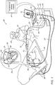
- Fig. 1 is a schematic, pictorial illustration of a catheter-based position-tracking and radiofrequency (RF) ablation system 20, in accordance with an embodiment of the present invention.
- System 20 comprises a catheter tip 40 (seen in inset 25) that is fitted at a distal end 22a of a shaft 22 of a catheter 21.
- RF ablation tip 40 comprises a spiral electrode 50 (detailed in Fig. 2 ) that further acts as a magnetic sensor and as a temperature sensor.
- spiral electrode 50 is used to ablate tissue of an ostium 51 of a PV in a heart 26.
- the proximal end of catheter 21 is connected to a control console 24 comprising an RF ablative power source 45.
- An ablation protocol comprising ablation parameters is stored in a memory 48 of console 24.
- Physician 30 inserts distal end 22a of shaft 22 through a sheath 23 into heart 26 of a patient 28 lying on a table 29. Physician 30 advances the distal end of shaft 22 to a target location in heart 26 by manipulating shaft 22 using a manipulator 32 near the proximal end of the catheter and/or deflection from the sheath 23. During the insertion of distal end 22a, catheter tip 40 is maintained inside sheath 23 to minimize vascular trauma along the way to target location.
- physician 30 navigates the distal end of shaft 22 to the target location by tracking a direction of catheter tip 40.
- console 24 receives signals from spiral electrode 50 at catheter tip 40, which acts as a magnetic sensor in response to magnetic fields from external field generators 36.
- Magnetic field generators 36 are placed at known positions external to patient 28, e.g., below patient table 29.
- Console 24 also comprises a driver circuit 34, configured to drive magnetic field generators 36.
- a processor 41 of the system estimates a direction of catheter tip 40 in the heart and, optionally, presents the tracked direction on a display 27, e.g., relative to an orientation of an axis of approximate symmetry of ostium 51.
- console 24 drives a display 27, which shows the tracked position of catheter tip 40 inside heart 26.
- physician 30 retracts sheath 23 and further manipulates shaft 22 to navigate catheter tip 40 to an ostium 51 the pulmonary vein.
- the physician causes RF electric currents to be passed between spiral electrode 50 on tip 40 and an indifferent (i.e., neutral) electrode patch that is coupled externally to the subject, e.g., to the subject's back.
- the patch can be a single electrode or made of several electrodes, such as electrodes 38, which are shown connected by wires running in a cable 37.
- Processor 41 adjusts the parameters of the ablating currents by outputting appropriate instructions to RF generator 45 that generates the currents.
- processor 41 includes a temperature sensing module 47.
- temperature sensing module 47 receives electrical impedance signals, measured between the two ends of spiral electrodes 50 and conducted by wires running through shaft 22 to processor 41.
- Processor 41 is typically a general-purpose computer, with suitable front end and (a) ECG interface circuits 44 for receiving ECG signals from electrodes 38, and (b) an electrical interface circuit 55 for receiving signals from catheter 21, as well as for applying RF energy treatment via catheter 21 in a left atrium of heart 26 and for controlling the other components of system 20.
- Processor 41 typically comprises a software in a memory 48 of system 20 that is programmed to carry out the functions described herein.
- the software may be downloaded to the computer in electronic form, over a network, for example, or it may, alternatively or additionally, be provided and/or stored on non-transitory tangible media, such as magnetic, optical, or electronic memory.
- processor 41 runs a dedicated algorithm as disclosed herein, included in Fig. 3 , that enables processor 41 to perform the disclosed steps, as further described below.
- Fig. 1 describes a tip catheter
- the principles of the present technique apply to any catheter having a distal end fitted with multiple electrodes, such as Pentaray and Octaray catheters (made by Biosense-Webster).
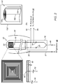
- Fig. 2 is a schematic, pictorial illustration of catheter tip 40 of the catheter of Fig. 1 comprising a spiral multi-purpose electrode 50 and its electrical interface circuit 55, in accordance with an embodiment of the invention.
- Electrical interface circuit 55 comprises conductors (52, 54, 46, 49) and capacitors (57, 59) or other suitable high-pass filters, and is used for (a) transferring a radiofrequency (RF) ablation signal to electrode 50 for ablating tissue in the body, (b) outputting a voltage that develops across electrode 50 in response to an external magnetic field, for measuring a position of the distal end in the body, and (c) transferring electrical current through electrode 50 for measuring a resistivity that is indicative of tissue temperature in a vicinity of electrode 50.
- RF radiofrequency
- electrode 50 is formed as a 2D planar high-density metal spiral. While the shown outline of the spiral electrode is of a square, any general rectilinear, curve or curvilinear spiral shape is possible, and in particular elliptical or circular shapes.
- the metal spiral is disposed on a flexible PCB 60, seen in cross-section. However, other types of substrates that can be manufactured to conform to the shape of the tip may be used.
- the center of the spiral is electrically connected to a conductor 52 on the backside of the PCB, using a via 62 in PCB 60. The perimeter of the spiral is connected to a conductor 54.
- Spiral electrode 50 is able to transfer RF ablation power and act as an ablation electrode. Furthermore, since the ablation RF power is connected to both ends of the spiral, i.e., by short circuiting conductors 52 and 54 into a single conductor 49 (proximally to isolating capacitors 57 and 59), no RF power is transferred along the lines of the spiral, with all the power transferred by conductor 49, out from the spiral surface, through the patient, to a return electrode 38 attached to the patient skin, and further via cable 37 to close an electrical circuit at generator 45 output leads.
- Spiral electrode 50 can act as a single axis magnetic sensor that is responsive to alternating magnetic fields traversing the spiral electrode, the fields generating potentials v f across the two ends of conductors 46.
- the alternating magnetic fields have frequencies typically equal to approximately 20 kHz, so they can be easily isolated from the ablation power using capacitors 57 and 59.
- the low frequency potentials v f can be used to find the position and orientation of the sensor, so that the electrode acts as a location sensor.
- the metal of the spiral changes its specific resistance with temperature, in a very well-known relation, which depends on the composition of the electrode material. Measuring the resistance R of the spiral between conductors 46 thus provides a temperature measurement using module 47.
- the spiral electrode can thus act as a resistance thermometer.
- the aforementioned electrically isolating capacitors 57 and 59 ensure that the resistance measured is that of the spiral itself, and not, for example, a resistance weighted by the output resistance of generator 45.
- the disclosed spiral electrode 150 can alternatively be disposed on a three-dimensional dome-shaped distal tip 140 of a catheter, whereby a flexible PCB with the spiral traces is conformed over the dome.
- spiral electrode 150 is disposed in this three-dimensional shape, with the center of the spiral being electrically connected to a conductor 152 and the perimeter of the spiral is connected to a conductor 154.
- cooling fluid flows via irrigation holes (not shown) in electrodes 50 to cool ablated tissue.
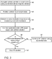
- Fig. 3 is a flow chart that schematically illustrates a method for using spiral electrode 50 of catheter tip 40 of Fig. 2 for position sensing, radiofrequency (RF) ablation, and temperature sensing, in accordance with an embodiment of the invention.
- the algorithm carries out a process that begins when physician 30 navigates catheter tip 40 to a target tissue location within heart 26 of a patient, such as at ostium 51, using spiral electrode 50 as a magnetic sensor, at a catheter tip navigation step 80.
- physician 30 positions the catheter tip at ostium 51, at a catheter tip positioning step 82. In the process, physician 30 brings catheter tip 40 into contact with target tissue.
- processor 41 measures, using impedance sensing module 47, the resistance of spiral electrode 50, to determine electrode temperature, at an electrode temperature measurement step 84.
- physician 30 controls interface circuits 44 to connect spiral electrode 50 to RF power supply 45 and to apply ablative energy via spiral electrode 50, at an RF ablation step 86.
- processor 41 measures electrode 50 temperature and compares the measured temperature to a preset maximal temperature, at a temperature checking step 88.
- processor 41 controls interface circuits 44 to continue applying the RF power via electrode 50, at a continued RF power application step 90.
- processor 41 controls interface circuits 44 to disconnect the RF power source from electrode 50, at a switching RF power off step 92.
- the methods and systems described herein can also be used in other applications that require RF ablation of body tissue, such as, for example, in renal denervation, cerebrovascular applications and in otolaryngology.
Landscapes
- Health & Medical Sciences (AREA)
- Life Sciences & Earth Sciences (AREA)
- Engineering & Computer Science (AREA)
- Surgery (AREA)
- Public Health (AREA)
- Animal Behavior & Ethology (AREA)
- Veterinary Medicine (AREA)
- General Health & Medical Sciences (AREA)
- Molecular Biology (AREA)
- Biomedical Technology (AREA)
- Heart & Thoracic Surgery (AREA)
- Medical Informatics (AREA)
- Physics & Mathematics (AREA)
- Nuclear Medicine, Radiotherapy & Molecular Imaging (AREA)
- Plasma & Fusion (AREA)
- Otolaryngology (AREA)
- Cardiology (AREA)
- Human Computer Interaction (AREA)
- Biophysics (AREA)
- Pathology (AREA)
- Robotics (AREA)
- Surgical Instruments (AREA)
Abstract
Description
- The present invention relates generally to medical probes, and particularly to cardiac sensing and ablation catheters.
- Cardiac catheters for tissue ablation may include multiple sensors and ablation electrodes at their distal end with the different devices typically electrically isolated one of the other. For example, temperature sensors may be embedded in an area covered by an ablation electrode to measure an ablation temperature of that electrode, but have separate electrical conductors.
- An embodiment of the present invention provides an electrical apparatus including a spiral electrode and an interface circuit. The spiral electrode is disposed on a distal end of a probe for insertion into a body of a patient. The interface circuit is configured to (a) transfer a radiofrequency (RF) ablation signal to the electrode for ablating tissue in the body, (b) output a voltage that develops across the electrode in response to an external magnetic field, for measuring a position of the distal end in the body, and (c) transfer electrical current through the electrode for measuring a resistivity that is indicative of tissue temperature in a vicinity of the electrode.
- In some embodiments, the spiral electrode is configured as a single axis coil position sensor.
- In some embodiments, the spiral electrode is disposed on a first facet of a Printed Circuit Board (PCB), wherein a first end of the spiral electrode is disposed on the first facet and a second end of the spiral electrode is connected to a second facet of the PCB through a via hole.
- In an embodiment, the interface circuit includes high-pass filters on the conductors between a source of the RF ablation signal and the electrode.
- In another embodiment, the electrical apparatus further includes a surface electrode configured to close an electrical circuit for the RF ablation signal applied by the spiral electrode.
- In some embodiments, the interface circuit includes isolation capacitors on electrical conductors between the spiral electrode and a source of the RF ablation signal.
- There is additionally provided, in accordance with another embodiment of the present invention, a method including inserting a spiral electrode disposed on a distal end of a probe into a body of a patient. A radiofrequency (RF) ablation signal is transferred to the electrode for ablating tissue in the body. A voltage that develops across the electrode in response to an external magnetic field is outputted for measuring a position of the distal end in the body. Electrical current is transferred through the electrode for measuring a resistivity that is indicative of tissue temperature in a vicinity of the electrode.
- There is further provided, in accordance with another embodiment of the present invention, a manufacturing method including disposing a spiral electrode on a distal end of a probe for insertion into a body of a patient. An interface circuit is connected to the spiral electrode, with the interface circuit configured to (a) transfer a radiofrequency (RF) ablation signal to the electrode for ablating tissue in the body, (b) output a voltage that develops across the electrode in response to an external magnetic field, for measuring a position of the distal end in the body, and (c) transfer electrical current through the electrode for measuring a resistivity that is indicative of tissue temperature in a vicinity of the electrode.
- In some embodiments, disposing the spiral electrode includes disposing the spiral electrode, including a first end of the electrode, on a first facet of a Printed Circuit Board (PCB), and connecting a second end of the spiral electrode to a second facet of the PCB through a via hole.
- The present invention will be more fully understood from the following detailed description of the embodiments thereof, taken together with the drawings in which:
-
-
Fig. 1 is a schematic, pictorial illustration of a catheter-based position-tracking and radiofrequency (RF) ablation system, in accordance with an embodiment of the present invention; -
Fig. 2 is a schematic, pictorial illustration of the catheter tip of the catheter ofFig. 1 comprising a spiral multi-purpose electrode and its conductors, in accordance with an embodiment of the invention; and -
Fig. 3 is a flow chart that schematically illustrates a method for using the spiral electrode of the catheter tip ofFig. 2 for position sensing, radiofrequency (RF) ablation, and temperature sensing, in accordance with an embodiment of the invention. - A catheter used for radiofrequency (RF) ablation requires an electrode capable of delivering the ablation power. In addition, the catheter position may be tracked, and electrode temperature measured during ablation. These three conditions may be served by three separate systems: an electrode, a tracking device such as a single- or triple-axis magnetic sensor, and a temperature sensor such as a thermocouple. The three separate systems require three separate sets of connections, some of which may themselves be problematic. (For example, the constantan in copper-constantan thermocouples is brittle and easily broken.) Notwithstanding the existence of problems, integration of three separate systems on a tip of a catheter tip is inherently complicated.
- Embodiments of the present invention that are described hereinafter use one electrode which is able to provide the three functions. In some embodiments, a spiral electrode is disposed on a distal end of a probe for insertion into a body of a patient. An interface circuit of an electrical apparatus is configured to (a) transfer a radiofrequency (RF) ablation signal to the electrode for ablating tissue in the body, (b) output a voltage that develops across the electrode in response to an external magnetic field, for measuring a position of the distal end in the body, (c) and transfer electrical current through the electrode for measuring a resistivity that is indicative of tissue temperature in a vicinity of the electrode.
- In some embodiments, the electrode is formed as a planar high-density spiral on one side of a flexible printed circuit board (PCB), with one end of the spiral being connected on one facet of the PCB. The other facet of the PCB is used to connect to the other end of the spiral through a plated hold ("via") in the PCB. The spiral is typically formed from metal, such as gold. In one embodiment, the spiral is in the form of an approximately 4 mm × 4 mm square, the lines of the spiral being approximately 25 µm wide separated by approximately 25 µm. Any general spiral shape in rectilinear, curves or curvilinear spiral is possible, and in particular elliptical or circular shapes may be utilized.
- As used herein, the terms "about" or "approximately" for any numerical values or ranges indicate a suitable dimensional tolerance that allows the component or collection of components to function for its intended purpose as described herein. More specifically, "about" or "approximately" may refer to the range of values ±20% of the recited value, e.g. "about 90%" may refer to the range of values from 71% to 99%.
- The spiral has a large area, and thus is able to transfer RF ablation power and act as an ablation electrode. Furthermore, since the ablation RF power is connected to both ends of the spiral, as shown below, no RF power is transferred along the lines of the spiral. Instead, all the power transfers out from the spiral surface, through the patient, and to a return electrode attached to the patient's skin. The ablation RF power typically has a frequency range of 350 - 500 kHz, which, in an embodiment, is provided to the spiral electrode through isolating capacitors (or other suitable high-pass filters), as shown below.
- Since the electrode is in the form of a spiral, it can act as a single axis magnetic sensor that is responsive to alternating magnetic fields traversing the spiral electrode, the fields generating potentials vf across the two ends of the spiral. (The alternating magnetic fields have frequencies typically equal to approximately 20 kHz, so they can be easily isolated from the ablation power, using, for example, isolating capacitors). The potentials vf can be used to find the position and orientation of the sensor, so that the electrode acts as a location sensor.
- The specific resistance of the metal (e.g., gold) spiral changes with its with temperature, in a very well-known relation (the temperature coefficient of gold is 0.003715 °C-1). Measuring the resistance R of the spiral thus provides a measure of the temperature. For example, a gold spiral having a resistance of 30 Ω (the approximate resistance of the 4 mm × 4 mm spiral described above) at 20 °C has a resistance of 30.1Ω at 21 °C. The resistance R of the spiral may be measured using an impedance reading circuitry, for example, by connecting the spiral as one arm of a Wheatstone bridge. The electrode can thus act as a resistance thermometer. In an embodiment, the aforementioned electrically isolating capacitors ensure that the resistance measured is that of the spiral.
- There is no restriction as to the type of catheter for which a spiral of the invention may be used, i.e., the spiral may be incorporated into a focal, basket, balloon, lasso, or other type of catheter.
- There is also no requirement for implementation of all three functions of a spiral. Thus, in some embodiments only one function is used, in other embodiments only two of the three functions are used, and in other embodiments all three functions are used.
- By providing a multipurpose electrode of a catheter as described above, the complexity and price of a catheter may be lowered and thereby increase availability of catheter-based RF ablation treatments.
-
Fig. 1 is a schematic, pictorial illustration of a catheter-based position-tracking and radiofrequency (RF)ablation system 20, in accordance with an embodiment of the present invention.System 20 comprises a catheter tip 40 (seen in inset 25) that is fitted at adistal end 22a of ashaft 22 of acatheter 21.RF ablation tip 40 comprises a spiral electrode 50 (detailed inFig. 2 ) that further acts as a magnetic sensor and as a temperature sensor. In the embodiment described herein,spiral electrode 50 is used to ablate tissue of anostium 51 of a PV in aheart 26. - The proximal end of
catheter 21 is connected to acontrol console 24 comprising an RFablative power source 45. An ablation protocol comprising ablation parameters is stored in amemory 48 ofconsole 24. -
Physician 30 insertsdistal end 22a ofshaft 22 through asheath 23 intoheart 26 of a patient 28 lying on a table 29.Physician 30 advances the distal end ofshaft 22 to a target location inheart 26 by manipulatingshaft 22 using amanipulator 32 near the proximal end of the catheter and/or deflection from thesheath 23. During the insertion ofdistal end 22a,catheter tip 40 is maintained insidesheath 23 to minimize vascular trauma along the way to target location. - In an embodiment,
physician 30 navigates the distal end ofshaft 22 to the target location by tracking a direction ofcatheter tip 40. During navigation ofdistal end 22a inheart 26,console 24 receives signals fromspiral electrode 50 atcatheter tip 40, which acts as a magnetic sensor in response to magnetic fields fromexternal field generators 36.Magnetic field generators 36 are placed at known positions external topatient 28, e.g., below patient table 29.Console 24 also comprises adriver circuit 34, configured to drivemagnetic field generators 36. - For example, using the signal, a
processor 41 of the system estimates a direction ofcatheter tip 40 in the heart and, optionally, presents the tracked direction on adisplay 27, e.g., relative to an orientation of an axis of approximate symmetry ofostium 51. In an embodiment,console 24 drives adisplay 27, which shows the tracked position ofcatheter tip 40 insideheart 26. - The method of direction sensing using external magnetic fields is implemented in various medical applications, for example, in the CARTO™ system, produced by Biosense-Webster and is described in detail in
U.S. Patents 5,391,199 ,6,690,963 ,6,484,118 ,6,239,724 ,6,618,612 and6,332,089 , inPCT Patent Publication WO 96/05768 U.S. Patent Application Publications 2002/0065455 A1 ,2003/0120150 A1 and2004/0068178 A1 , which prior applications are hereby incorporated by reference in their entirety herein into this application as if set forth in full with a copy attached in the Appendix. In an embodiment, signals fromspiral electrode 50 are further used for position sensing using the aforementioned CARTO™ system. - Once
distal end 22a ofshaft 22 has reachedheart 26,physician 30 retractssheath 23 and further manipulatesshaft 22 to navigatecatheter tip 40 to anostium 51 the pulmonary vein. Next, whilecatheter tip 40 contacts the tissue, the physician causes RF electric currents to be passed betweenspiral electrode 50 ontip 40 and an indifferent (i.e., neutral) electrode patch that is coupled externally to the subject, e.g., to the subject's back. The patch can be a single electrode or made of several electrodes, such aselectrodes 38, which are shown connected by wires running in acable 37.Processor 41 adjusts the parameters of the ablating currents by outputting appropriate instructions toRF generator 45 that generates the currents. - To further perform its functions,
processor 41 includes atemperature sensing module 47. In the exemplified system,temperature sensing module 47 receives electrical impedance signals, measured between the two ends ofspiral electrodes 50 and conducted by wires running throughshaft 22 toprocessor 41. -
Processor 41 is typically a general-purpose computer, with suitable front end and (a)ECG interface circuits 44 for receiving ECG signals fromelectrodes 38, and (b) anelectrical interface circuit 55 for receiving signals fromcatheter 21, as well as for applying RF energy treatment viacatheter 21 in a left atrium ofheart 26 and for controlling the other components ofsystem 20.Processor 41 typically comprises a software in amemory 48 ofsystem 20 that is programmed to carry out the functions described herein. The software may be downloaded to the computer in electronic form, over a network, for example, or it may, alternatively or additionally, be provided and/or stored on non-transitory tangible media, such as magnetic, optical, or electronic memory. In particular,processor 41 runs a dedicated algorithm as disclosed herein, included inFig. 3 , that enablesprocessor 41 to perform the disclosed steps, as further described below. - While
Fig. 1 describes a tip catheter, the principles of the present technique apply to any catheter having a distal end fitted with multiple electrodes, such as Pentaray and Octaray catheters (made by Biosense-Webster). -
Fig. 2 is a schematic, pictorial illustration ofcatheter tip 40 of the catheter ofFig. 1 comprising a spiralmulti-purpose electrode 50 and itselectrical interface circuit 55, in accordance with an embodiment of the invention.Electrical interface circuit 55 comprises conductors (52, 54, 46, 49) and capacitors (57, 59) or other suitable high-pass filters, and is used for (a) transferring a radiofrequency (RF) ablation signal to electrode 50 for ablating tissue in the body, (b) outputting a voltage that develops acrosselectrode 50 in response to an external magnetic field, for measuring a position of the distal end in the body, and (c) transferring electrical current throughelectrode 50 for measuring a resistivity that is indicative of tissue temperature in a vicinity ofelectrode 50. - As seen,
electrode 50 is formed as a 2D planar high-density metal spiral. While the shown outline of the spiral electrode is of a square, any general rectilinear, curve or curvilinear spiral shape is possible, and in particular elliptical or circular shapes. In an embodiment, the metal spiral is disposed on aflexible PCB 60, seen in cross-section. However, other types of substrates that can be manufactured to conform to the shape of the tip may be used. As further seen, the center of the spiral is electrically connected to aconductor 52 on the backside of the PCB, using a via 62 inPCB 60. The perimeter of the spiral is connected to a conductor 54. -
Spiral electrode 50 is able to transfer RF ablation power and act as an ablation electrode. Furthermore, since the ablation RF power is connected to both ends of the spiral, i.e., byshort circuiting conductors 52 and 54 into a single conductor 49 (proximally to isolatingcapacitors 57 and 59), no RF power is transferred along the lines of the spiral, with all the power transferred byconductor 49, out from the spiral surface, through the patient, to areturn electrode 38 attached to the patient skin, and further viacable 37 to close an electrical circuit atgenerator 45 output leads. - Further shown are
conductors 46.Spiral electrode 50 can act as a single axis magnetic sensor that is responsive to alternating magnetic fields traversing the spiral electrode, the fields generating potentials vf across the two ends ofconductors 46. (The alternating magnetic fields have frequencies typically equal to approximately 20 kHz, so they can be easily isolated from the ablationpower using capacitors - The metal of the spiral changes its specific resistance with temperature, in a very well-known relation, which depends on the composition of the electrode material. Measuring the resistance R of the spiral between
conductors 46 thus provides a temperaturemeasurement using module 47. The spiral electrode can thus act as a resistance thermometer. In an embodiment, the aforementionedelectrically isolating capacitors generator 45. - As
inset 130 ofFig. 2 shows, the disclosedspiral electrode 150 can alternatively be disposed on a three-dimensional dome-shapeddistal tip 140 of a catheter, whereby a flexible PCB with the spiral traces is conformed over the dome. As further seen,spiral electrode 150 is disposed in this three-dimensional shape, with the center of the spiral being electrically connected to aconductor 152 and the perimeter of the spiral is connected to aconductor 154. - The pictorial side view shown in
Fig. 2 is chosen by way of example, where other embodiments are possible. For example, in another embodiment, cooling fluid flows via irrigation holes (not shown) inelectrodes 50 to cool ablated tissue. -
Fig. 3 is a flow chart that schematically illustrates a method for usingspiral electrode 50 ofcatheter tip 40 ofFig. 2 for position sensing, radiofrequency (RF) ablation, and temperature sensing, in accordance with an embodiment of the invention. The algorithm, according to the presented embodiment, carries out a process that begins whenphysician 30 navigatescatheter tip 40 to a target tissue location withinheart 26 of a patient, such as atostium 51, usingspiral electrode 50 as a magnetic sensor, at a cathetertip navigation step 80. - Next,
physician 30 positions the catheter tip atostium 51, at a cathetertip positioning step 82. In the process,physician 30 bringscatheter tip 40 into contact with target tissue. - Next,
processor 41 measures, usingimpedance sensing module 47, the resistance ofspiral electrode 50, to determine electrode temperature, at an electrodetemperature measurement step 84. - Next,
physician 30 controls interfacecircuits 44 to connectspiral electrode 50 toRF power supply 45 and to apply ablative energy viaspiral electrode 50, at anRF ablation step 86. - During application of ablative energy,
processor 41 measures electrode 50 temperature and compares the measured temperature to a preset maximal temperature, at atemperature checking step 88. - If the temperature is below the preset maximal temperature,
processor 41 controls interfacecircuits 44 to continue applying the RF power viaelectrode 50, at a continued RFpower application step 90. - If, on the other hand, the temperature is above the preset maximal temperature,
processor 41 controls interfacecircuits 44 to disconnect the RF power source fromelectrode 50, at a switching RF power offstep 92. - The example flow chart shown in
Fig. 3 is chosen purely for the sake of conceptual clarity. In alternative embodiments, additional steps may be performed, such as comparing the temperature ofelectrode 50 to a minimal preset temperature and disconnectingelectrode 50 from the RF power source if the temperature ofelectrode 50 has not exceeded the minimal preset temperature within a given time duration after the start of application of ablative RF energy (indicative of electrode immersed in blood). - Although the embodiments described herein mainly address pulmonary vein isolation, the methods and systems described herein can also be used in other applications that require RF ablation of body tissue, such as, for example, in renal denervation, cerebrovascular applications and in otolaryngology.
- It will thus be appreciated that the embodiments described above are cited by way of example, and that the present invention is not limited to what has been particularly shown and described hereinabove. Rather, the scope of the present invention includes both combinations and sub-combinations of the various features described hereinabove, as well as variations and modifications thereof which would occur to persons skilled in the art upon reading the foregoing description and which are not disclosed in the prior art. Documents incorporated by reference in the present patent application are to be considered an integral part of the application except that to the extent any terms are defined in these incorporated documents in a manner that conflicts with the definitions made explicitly or implicitly in the present specification, only the definitions in the present specification should be considered.
Claims (9)
- An electrical apparatus, comprising:a spiral electrode disposed on a distal end of a probe for insertion into a body of a patient; andan interface circuit, which is configured to:transfer a radiofrequency (RF) ablation signal to the electrode for ablating tissue in the body;output a voltage that develops across the electrode in response to an external magnetic field, for measuring a position of the distal end in the body; andtransfer electrical current through the electrode for measuring a resistivity that is indicative of tissue temperature in a vicinity of the electrode.
- The electrical apparatus according to claim 1, wherein the spiral electrode is configured as a single axis coil position sensor.
- The electrical apparatus according to claim 1, wherein the spiral electrode is disposed on a first facet of a Printed Circuit Board (PCB), wherein a first end of the spiral electrode is disposed on the first facet and a second end of the spiral electrode is connected to a second facet of the PCB through a via hole.
- The electrical apparatus according to claim 1, wherein the interface circuit comprises high-pass filters on the conductors between a source of the RF ablation signal and the electrode.
- The electrical apparatus according to claim 1, and comprising a surface electrode configured to close an electrical circuit for the RF ablation signal applied by the spiral electrode.
- The electrical apparatus according to claim 1, wherein the interface circuit comprises isolation capacitors on electrical conductors between the spiral electrode and a source of the RF ablation signal.
- A method, comprising:inserting a spiral electrode disposed on a distal end of a probe into a body of a patient;transferring a radiofrequency (RF) ablation signal to the electrode for ablating tissue in the body;outputting a voltage that develops across the electrode in response to an external magnetic field, for measuring a position of the distal end in the body; andtransferring electrical current through the electrode for measuring a resistivity that is indicative of tissue temperature in a vicinity of the electrode.
- A manufacturing method, comprising:disposing a spiral electrode on a distal end of a probe for insertion into a body of a patient; andconnecting to the spiral electrode an interface circuit, which is configured to:transfer a radiofrequency (RF) ablation signal to the electrode for ablating tissue in the body;output a voltage that develops across the electrode in response to an external magnetic field, for measuring a position of the distal end in the body; andtransfer electrical current through the electrode for measuring a resistivity that is indicative of tissue temperature in a vicinity of the electrode.
- The manufacturing method according to claim 8, wherein disposing the spiral electrode comprises disposing the spiral electrode, including a first end of the electrode, on a first facet of a Printed Circuit Board (PCB), and connecting a second end of the spiral electrode to a second facet of the PCB through a via hole.
Applications Claiming Priority (1)
| Application Number | Priority Date | Filing Date | Title |
|---|---|---|---|
| US16/730,128 US11712295B2 (en) | 2019-12-30 | 2019-12-30 | Multi-purpose sensing and radiofrequency (RF) ablation spiral electrode for catheter |
Publications (3)
| Publication Number | Publication Date |
|---|---|
| EP3845177A1 true EP3845177A1 (en) | 2021-07-07 |
| EP3845177C0 EP3845177C0 (en) | 2024-02-14 |
| EP3845177B1 EP3845177B1 (en) | 2024-02-14 |
Family
ID=74003714
Family Applications (1)
| Application Number | Title | Priority Date | Filing Date |
|---|---|---|---|
| EP20217531.1A Active EP3845177B1 (en) | 2019-12-30 | 2020-12-29 | Multi-purpose sensing and radiofrequency (rf) ablation spiral electrode for catheter |
Country Status (5)
| Country | Link |
|---|---|
| US (2) | US11712295B2 (en) |
| EP (1) | EP3845177B1 (en) |
| JP (1) | JP7536638B2 (en) |
| CN (2) | CN216365245U (en) |
| IL (1) | IL279677B2 (en) |
Families Citing this family (2)
| Publication number | Priority date | Publication date | Assignee | Title |
|---|---|---|---|---|
| US11712295B2 (en) * | 2019-12-30 | 2023-08-01 | Biosense Webster (Israel) Ltd. | Multi-purpose sensing and radiofrequency (RF) ablation spiral electrode for catheter |
| US20240366295A1 (en) * | 2021-07-26 | 2024-11-07 | Sigt, Llc | Tissue Ablation and Lesion Assessment System |
Citations (14)
| Publication number | Priority date | Publication date | Assignee | Title |
|---|---|---|---|---|
| US5391199A (en) | 1993-07-20 | 1995-02-21 | Biosense, Inc. | Apparatus and method for treating cardiac arrhythmias |
| WO1996005768A1 (en) | 1994-08-19 | 1996-02-29 | Biosense, Inc. | Medical diagnosis, treatment and imaging systems |
| US6239724B1 (en) | 1997-12-30 | 2001-05-29 | Remon Medical Technologies, Ltd. | System and method for telemetrically providing intrabody spatial position |
| US6332089B1 (en) | 1996-02-15 | 2001-12-18 | Biosense, Inc. | Medical procedures and apparatus using intrabody probes |
| US20020065455A1 (en) | 1995-01-24 | 2002-05-30 | Shlomo Ben-Haim | Medical diagnosis, treatment and imaging systems |
| US6484118B1 (en) | 2000-07-20 | 2002-11-19 | Biosense, Inc. | Electromagnetic position single axis system |
| US20030120150A1 (en) | 2001-12-21 | 2003-06-26 | Assaf Govari | Wireless position sensor |
| US6618612B1 (en) | 1996-02-15 | 2003-09-09 | Biosense, Inc. | Independently positionable transducers for location system |
| US20040068178A1 (en) | 2002-09-17 | 2004-04-08 | Assaf Govari | High-gradient recursive locating system |
| US20140266207A1 (en) * | 2013-03-13 | 2014-09-18 | MRI Interventions, Inc. | Electrical lead assemblies for mri-compatible medical devices and mri-compatible medical devices incorporating same |
| US20170042614A1 (en) * | 2008-11-11 | 2017-02-16 | Amr Salahieh | Ablation catheters |
| EP3340750A1 (en) * | 2016-12-23 | 2018-06-27 | Biosense Webster (Israel) Ltd. | Triple axis sensor on a single layer printed circuit |
| US20180214204A1 (en) * | 2015-07-08 | 2018-08-02 | The Johns Hopkins University | Tissue ablation and assessment system and method of use thereof |
| US20180280658A1 (en) * | 2017-04-03 | 2018-10-04 | Biosense Webster (Israel) Ltd. | Balloon catheter with ultrasonic transducers |
Family Cites Families (11)
| Publication number | Priority date | Publication date | Assignee | Title |
|---|---|---|---|---|
| US4938761A (en) * | 1989-03-06 | 1990-07-03 | Mdt Corporation | Bipolar electrosurgical forceps |
| US5913854A (en) | 1997-02-04 | 1999-06-22 | Medtronic, Inc. | Fluid cooled ablation catheter and method for making |
| US8211097B2 (en) * | 2009-02-13 | 2012-07-03 | Cutera, Inc. | Optimizing RF power spatial distribution using frequency control |
| US20110213355A1 (en) * | 2010-03-01 | 2011-09-01 | Vivant Medical, Inc. | Sensors On Patient Side for a Microwave Generator |
| CA2797130A1 (en) * | 2010-05-12 | 2011-11-17 | Shifamed Holdings, Llc | Low profile electrode assembly |
| US8543190B2 (en) * | 2010-07-30 | 2013-09-24 | Medtronic, Inc. | Inductive coil device on flexible substrate |
| US20130281851A1 (en) * | 2012-04-19 | 2013-10-24 | Kenneth L. Carr | Heating/sensing catheter apparatus for minimally invasive applications |
| US10646272B2 (en) | 2015-02-03 | 2020-05-12 | Shanghai Golden Leaf Med Tec Co., Ltd. | Radio-frequency ablation catheter having spiral structure and device thereof |
| US10905329B2 (en) * | 2016-06-09 | 2021-02-02 | Biosense Webster (Israel) Ltd. | Multi-function conducting elements for a catheter |
| US11246644B2 (en) * | 2018-04-05 | 2022-02-15 | Covidien Lp | Surface ablation using bipolar RF electrode |
| US11712295B2 (en) * | 2019-12-30 | 2023-08-01 | Biosense Webster (Israel) Ltd. | Multi-purpose sensing and radiofrequency (RF) ablation spiral electrode for catheter |
-
2019
- 2019-12-30 US US16/730,128 patent/US11712295B2/en active Active
-
2020
- 2020-12-22 IL IL279677A patent/IL279677B2/en unknown
- 2020-12-28 JP JP2020218528A patent/JP7536638B2/en active Active
- 2020-12-29 EP EP20217531.1A patent/EP3845177B1/en active Active
- 2020-12-30 CN CN202023298077.1U patent/CN216365245U/en active Active
- 2020-12-30 CN CN202011620549.2A patent/CN113116509A/en active Pending
-
2023
- 2023-07-14 US US18/352,877 patent/US20230355305A1/en active Pending
Patent Citations (15)
| Publication number | Priority date | Publication date | Assignee | Title |
|---|---|---|---|---|
| US5391199A (en) | 1993-07-20 | 1995-02-21 | Biosense, Inc. | Apparatus and method for treating cardiac arrhythmias |
| WO1996005768A1 (en) | 1994-08-19 | 1996-02-29 | Biosense, Inc. | Medical diagnosis, treatment and imaging systems |
| US6690963B2 (en) | 1995-01-24 | 2004-02-10 | Biosense, Inc. | System for determining the location and orientation of an invasive medical instrument |
| US20020065455A1 (en) | 1995-01-24 | 2002-05-30 | Shlomo Ben-Haim | Medical diagnosis, treatment and imaging systems |
| US6332089B1 (en) | 1996-02-15 | 2001-12-18 | Biosense, Inc. | Medical procedures and apparatus using intrabody probes |
| US6618612B1 (en) | 1996-02-15 | 2003-09-09 | Biosense, Inc. | Independently positionable transducers for location system |
| US6239724B1 (en) | 1997-12-30 | 2001-05-29 | Remon Medical Technologies, Ltd. | System and method for telemetrically providing intrabody spatial position |
| US6484118B1 (en) | 2000-07-20 | 2002-11-19 | Biosense, Inc. | Electromagnetic position single axis system |
| US20030120150A1 (en) | 2001-12-21 | 2003-06-26 | Assaf Govari | Wireless position sensor |
| US20040068178A1 (en) | 2002-09-17 | 2004-04-08 | Assaf Govari | High-gradient recursive locating system |
| US20170042614A1 (en) * | 2008-11-11 | 2017-02-16 | Amr Salahieh | Ablation catheters |
| US20140266207A1 (en) * | 2013-03-13 | 2014-09-18 | MRI Interventions, Inc. | Electrical lead assemblies for mri-compatible medical devices and mri-compatible medical devices incorporating same |
| US20180214204A1 (en) * | 2015-07-08 | 2018-08-02 | The Johns Hopkins University | Tissue ablation and assessment system and method of use thereof |
| EP3340750A1 (en) * | 2016-12-23 | 2018-06-27 | Biosense Webster (Israel) Ltd. | Triple axis sensor on a single layer printed circuit |
| US20180280658A1 (en) * | 2017-04-03 | 2018-10-04 | Biosense Webster (Israel) Ltd. | Balloon catheter with ultrasonic transducers |
Also Published As
| Publication number | Publication date |
|---|---|
| EP3845177C0 (en) | 2024-02-14 |
| IL279677A (en) | 2021-06-30 |
| JP2021109102A (en) | 2021-08-02 |
| JP7536638B2 (en) | 2024-08-20 |
| US20210196371A1 (en) | 2021-07-01 |
| IL279677B2 (en) | 2024-06-01 |
| CN216365245U (en) | 2022-04-26 |
| US20230355305A1 (en) | 2023-11-09 |
| EP3845177B1 (en) | 2024-02-14 |
| US11712295B2 (en) | 2023-08-01 |
| IL279677B1 (en) | 2024-02-01 |
| CN113116509A (en) | 2021-07-16 |
Similar Documents
| Publication | Publication Date | Title |
|---|---|---|
| CN109700523B (en) | Esophageal probe with transmission coil | |
| EP3834758A1 (en) | Catheter with plurality of sensing electrodes used as ablation electrode | |
| US20210015552A1 (en) | Patch electrode including temperature sensing circuit and methods of using same | |
| US11207125B2 (en) | Effective parasitic capacitance minimization for micro ablation electrode | |
| CN105125283B (en) | Catheter electrodes with multiple thermocouples | |
| EP3861954A1 (en) | Irrigated balloon catheter with flexible circuit electrode assembly | |
| EP2875779A1 (en) | Flexible multiple-arm diagnostic catheter | |
| US20230355305A1 (en) | Multi-Purpose Sensing and Radiofrequency (RF) Ablation Spiral Electrode for Catheter | |
| JP2021532870A (en) | Flexible circuit tip for split tip catheter | |
| CN109276310B (en) | Ablation Power Supply | |
| US20250144368A1 (en) | Measurement of distal end dimension of basket catheters using magnetic fields | |
| US20260076736A1 (en) | Balloon catheter having ablation and return electrodes | |
| EP3944830A1 (en) | Controlling irreversible electroporation ablation using a focal catheter having contact-force and temperature sensors | |
| US20240173071A1 (en) | Flexible Distal-End Assembly with Double-Sided Electrode Array and Irrigation | |
| US12082875B2 (en) | Balloon catheter having a coil for sensing tissue temperature and position of the balloon | |
| US11794004B2 (en) | Electroporation with cooling | |
| JP7861296B2 (en) | Ablation and mapping using a single multi-electrode catheter | |
| EP3838206A1 (en) | A flexible circuit for use with a catheter and related manufacturing method | |
| IL302975A (en) | Devices, systems and methods for perforating septal tissue |
Legal Events
| Date | Code | Title | Description |
|---|---|---|---|
| PUAI | Public reference made under article 153(3) epc to a published international application that has entered the european phase |
Free format text: ORIGINAL CODE: 0009012 |
|
| STAA | Information on the status of an ep patent application or granted ep patent |
Free format text: STATUS: THE APPLICATION HAS BEEN PUBLISHED |
|
| AK | Designated contracting states |
Kind code of ref document: A1 Designated state(s): AL AT BE BG CH CY CZ DE DK EE ES FI FR GB GR HR HU IE IS IT LI LT LU LV MC MK MT NL NO PL PT RO RS SE SI SK SM TR |
|
| STAA | Information on the status of an ep patent application or granted ep patent |
Free format text: STATUS: REQUEST FOR EXAMINATION WAS MADE |
|
| 17P | Request for examination filed |
Effective date: 20211025 |
|
| RBV | Designated contracting states (corrected) |
Designated state(s): AL AT BE BG CH CY CZ DE DK EE ES FI FR GB GR HR HU IE IS IT LI LT LU LV MC MK MT NL NO PL PT RO RS SE SI SK SM TR |
|
| RAP3 | Party data changed (applicant data changed or rights of an application transferred) |
Owner name: BIOSENSE WEBSTER (ISRAEL) LTD. |
|
| GRAP | Despatch of communication of intention to grant a patent |
Free format text: ORIGINAL CODE: EPIDOSNIGR1 |
|
| STAA | Information on the status of an ep patent application or granted ep patent |
Free format text: STATUS: GRANT OF PATENT IS INTENDED |
|
| INTG | Intention to grant announced |
Effective date: 20230517 |
|
| GRAJ | Information related to disapproval of communication of intention to grant by the applicant or resumption of examination proceedings by the epo deleted |
Free format text: ORIGINAL CODE: EPIDOSDIGR1 |
|
| STAA | Information on the status of an ep patent application or granted ep patent |
Free format text: STATUS: REQUEST FOR EXAMINATION WAS MADE |
|
| GRAP | Despatch of communication of intention to grant a patent |
Free format text: ORIGINAL CODE: EPIDOSNIGR1 |
|
| STAA | Information on the status of an ep patent application or granted ep patent |
Free format text: STATUS: GRANT OF PATENT IS INTENDED |
|
| INTG | Intention to grant announced |
Effective date: 20230630 |
|
| GRAS | Grant fee paid |
Free format text: ORIGINAL CODE: EPIDOSNIGR3 |
|
| GRAA | (expected) grant |
Free format text: ORIGINAL CODE: 0009210 |
|
| STAA | Information on the status of an ep patent application or granted ep patent |
Free format text: STATUS: THE PATENT HAS BEEN GRANTED |
|
| AK | Designated contracting states |
Kind code of ref document: B1 Designated state(s): AL AT BE BG CH CY CZ DE DK EE ES FI FR GB GR HR HU IE IS IT LI LT LU LV MC MK MT NL NO PL PT RO RS SE SI SK SM TR |
|
| REG | Reference to a national code |
Ref country code: GB Ref legal event code: FG4D |
|
| REG | Reference to a national code |
Ref country code: CH Ref legal event code: EP |
|
| REG | Reference to a national code |
Ref country code: DE Ref legal event code: R096 Ref document number: 602020025608 Country of ref document: DE |
|
| REG | Reference to a national code |
Ref country code: IE Ref legal event code: FG4D |
|
| U01 | Request for unitary effect filed |
Effective date: 20240305 |
|
| U07 | Unitary effect registered |
Designated state(s): AT BE BG DE DK EE FI FR IT LT LU LV MT NL PT SE SI Effective date: 20240312 |
|
| PG25 | Lapsed in a contracting state [announced via postgrant information from national office to epo] |
Ref country code: IS Free format text: LAPSE BECAUSE OF FAILURE TO SUBMIT A TRANSLATION OF THE DESCRIPTION OR TO PAY THE FEE WITHIN THE PRESCRIBED TIME-LIMIT Effective date: 20240614 |
|
| PG25 | Lapsed in a contracting state [announced via postgrant information from national office to epo] |
Ref country code: GR Free format text: LAPSE BECAUSE OF FAILURE TO SUBMIT A TRANSLATION OF THE DESCRIPTION OR TO PAY THE FEE WITHIN THE PRESCRIBED TIME-LIMIT Effective date: 20240515 |
|
| PG25 | Lapsed in a contracting state [announced via postgrant information from national office to epo] |
Ref country code: HR Free format text: LAPSE BECAUSE OF FAILURE TO SUBMIT A TRANSLATION OF THE DESCRIPTION OR TO PAY THE FEE WITHIN THE PRESCRIBED TIME-LIMIT Effective date: 20240214 Ref country code: RS Free format text: LAPSE BECAUSE OF FAILURE TO SUBMIT A TRANSLATION OF THE DESCRIPTION OR TO PAY THE FEE WITHIN THE PRESCRIBED TIME-LIMIT Effective date: 20240514 |
|
| PG25 | Lapsed in a contracting state [announced via postgrant information from national office to epo] |
Ref country code: ES Free format text: LAPSE BECAUSE OF FAILURE TO SUBMIT A TRANSLATION OF THE DESCRIPTION OR TO PAY THE FEE WITHIN THE PRESCRIBED TIME-LIMIT Effective date: 20240214 |
|
| PG25 | Lapsed in a contracting state [announced via postgrant information from national office to epo] |
Ref country code: RS Free format text: LAPSE BECAUSE OF FAILURE TO SUBMIT A TRANSLATION OF THE DESCRIPTION OR TO PAY THE FEE WITHIN THE PRESCRIBED TIME-LIMIT Effective date: 20240514 Ref country code: NO Free format text: LAPSE BECAUSE OF FAILURE TO SUBMIT A TRANSLATION OF THE DESCRIPTION OR TO PAY THE FEE WITHIN THE PRESCRIBED TIME-LIMIT Effective date: 20240514 Ref country code: IS Free format text: LAPSE BECAUSE OF FAILURE TO SUBMIT A TRANSLATION OF THE DESCRIPTION OR TO PAY THE FEE WITHIN THE PRESCRIBED TIME-LIMIT Effective date: 20240614 Ref country code: HR Free format text: LAPSE BECAUSE OF FAILURE TO SUBMIT A TRANSLATION OF THE DESCRIPTION OR TO PAY THE FEE WITHIN THE PRESCRIBED TIME-LIMIT Effective date: 20240214 Ref country code: GR Free format text: LAPSE BECAUSE OF FAILURE TO SUBMIT A TRANSLATION OF THE DESCRIPTION OR TO PAY THE FEE WITHIN THE PRESCRIBED TIME-LIMIT Effective date: 20240515 Ref country code: ES Free format text: LAPSE BECAUSE OF FAILURE TO SUBMIT A TRANSLATION OF THE DESCRIPTION OR TO PAY THE FEE WITHIN THE PRESCRIBED TIME-LIMIT Effective date: 20240214 |
|
| PG25 | Lapsed in a contracting state [announced via postgrant information from national office to epo] |
Ref country code: PL Free format text: LAPSE BECAUSE OF FAILURE TO SUBMIT A TRANSLATION OF THE DESCRIPTION OR TO PAY THE FEE WITHIN THE PRESCRIBED TIME-LIMIT Effective date: 20240214 |
|
| PG25 | Lapsed in a contracting state [announced via postgrant information from national office to epo] |
Ref country code: PL Free format text: LAPSE BECAUSE OF FAILURE TO SUBMIT A TRANSLATION OF THE DESCRIPTION OR TO PAY THE FEE WITHIN THE PRESCRIBED TIME-LIMIT Effective date: 20240214 |
|
| PG25 | Lapsed in a contracting state [announced via postgrant information from national office to epo] |
Ref country code: SM Free format text: LAPSE BECAUSE OF FAILURE TO SUBMIT A TRANSLATION OF THE DESCRIPTION OR TO PAY THE FEE WITHIN THE PRESCRIBED TIME-LIMIT Effective date: 20240214 |
|
| PG25 | Lapsed in a contracting state [announced via postgrant information from national office to epo] |
Ref country code: CZ Free format text: LAPSE BECAUSE OF FAILURE TO SUBMIT A TRANSLATION OF THE DESCRIPTION OR TO PAY THE FEE WITHIN THE PRESCRIBED TIME-LIMIT Effective date: 20240214 |
|
| PG25 | Lapsed in a contracting state [announced via postgrant information from national office to epo] |
Ref country code: SK Free format text: LAPSE BECAUSE OF FAILURE TO SUBMIT A TRANSLATION OF THE DESCRIPTION OR TO PAY THE FEE WITHIN THE PRESCRIBED TIME-LIMIT Effective date: 20240214 |
|
| PG25 | Lapsed in a contracting state [announced via postgrant information from national office to epo] |
Ref country code: SM Free format text: LAPSE BECAUSE OF FAILURE TO SUBMIT A TRANSLATION OF THE DESCRIPTION OR TO PAY THE FEE WITHIN THE PRESCRIBED TIME-LIMIT Effective date: 20240214 Ref country code: SK Free format text: LAPSE BECAUSE OF FAILURE TO SUBMIT A TRANSLATION OF THE DESCRIPTION OR TO PAY THE FEE WITHIN THE PRESCRIBED TIME-LIMIT Effective date: 20240214 Ref country code: RO Free format text: LAPSE BECAUSE OF FAILURE TO SUBMIT A TRANSLATION OF THE DESCRIPTION OR TO PAY THE FEE WITHIN THE PRESCRIBED TIME-LIMIT Effective date: 20240214 Ref country code: CZ Free format text: LAPSE BECAUSE OF FAILURE TO SUBMIT A TRANSLATION OF THE DESCRIPTION OR TO PAY THE FEE WITHIN THE PRESCRIBED TIME-LIMIT Effective date: 20240214 |
|
| REG | Reference to a national code |
Ref country code: DE Ref legal event code: R097 Ref document number: 602020025608 Country of ref document: DE |
|
| U20 | Renewal fee for the european patent with unitary effect paid |
Year of fee payment: 5 Effective date: 20241107 |
|
| PLBE | No opposition filed within time limit |
Free format text: ORIGINAL CODE: 0009261 |
|
| STAA | Information on the status of an ep patent application or granted ep patent |
Free format text: STATUS: NO OPPOSITION FILED WITHIN TIME LIMIT |
|
| 26N | No opposition filed |
Effective date: 20241115 |
|
| PG25 | Lapsed in a contracting state [announced via postgrant information from national office to epo] |
Ref country code: MC Free format text: LAPSE BECAUSE OF FAILURE TO SUBMIT A TRANSLATION OF THE DESCRIPTION OR TO PAY THE FEE WITHIN THE PRESCRIBED TIME-LIMIT Effective date: 20240214 |
|
| REG | Reference to a national code |
Ref country code: CH Ref legal event code: PL |
|
| PG25 | Lapsed in a contracting state [announced via postgrant information from national office to epo] |
Ref country code: CH Free format text: LAPSE BECAUSE OF NON-PAYMENT OF DUE FEES Effective date: 20241231 |
|
| PG25 | Lapsed in a contracting state [announced via postgrant information from national office to epo] |
Ref country code: IE Free format text: LAPSE BECAUSE OF NON-PAYMENT OF DUE FEES Effective date: 20241229 |
|
| U20 | Renewal fee for the european patent with unitary effect paid |
Year of fee payment: 6 Effective date: 20251110 |
|
| PGFP | Annual fee paid to national office [announced via postgrant information from national office to epo] |
Ref country code: GB Payment date: 20251114 Year of fee payment: 6 |
|
| PG25 | Lapsed in a contracting state [announced via postgrant information from national office to epo] |
Ref country code: CY Free format text: LAPSE BECAUSE OF FAILURE TO SUBMIT A TRANSLATION OF THE DESCRIPTION OR TO PAY THE FEE WITHIN THE PRESCRIBED TIME-LIMIT Effective date: 20240214 |