EP3844567B1 - Dark flash photography with a stereo camera - Google Patents
Dark flash photography with a stereo camera Download PDFInfo
- Publication number
- EP3844567B1 EP3844567B1 EP19755750.7A EP19755750A EP3844567B1 EP 3844567 B1 EP3844567 B1 EP 3844567B1 EP 19755750 A EP19755750 A EP 19755750A EP 3844567 B1 EP3844567 B1 EP 3844567B1
- Authority
- EP
- European Patent Office
- Prior art keywords
- invisible
- visible
- light
- image
- wavelength
- Prior art date
- Legal status (The legal status is an assumption and is not a legal conclusion. Google has not performed a legal analysis and makes no representation as to the accuracy of the status listed.)
- Active
Links
Images



Classifications
-
- G—PHYSICS
- G03—PHOTOGRAPHY; CINEMATOGRAPHY; ANALOGOUS TECHNIQUES USING WAVES OTHER THAN OPTICAL WAVES; ELECTROGRAPHY; HOLOGRAPHY
- G03B—APPARATUS OR ARRANGEMENTS FOR TAKING PHOTOGRAPHS OR FOR PROJECTING OR VIEWING THEM; APPARATUS OR ARRANGEMENTS EMPLOYING ANALOGOUS TECHNIQUES USING WAVES OTHER THAN OPTICAL WAVES; ACCESSORIES THEREFOR
- G03B15/00—Special procedures for taking photographs; Apparatus therefor
- G03B15/02—Illuminating scene
- G03B15/03—Combinations of cameras with lighting apparatus; Flash units
- G03B15/05—Combinations of cameras with electronic flash apparatus; Electronic flash units
-
- G—PHYSICS
- G03—PHOTOGRAPHY; CINEMATOGRAPHY; ANALOGOUS TECHNIQUES USING WAVES OTHER THAN OPTICAL WAVES; ELECTROGRAPHY; HOLOGRAPHY
- G03B—APPARATUS OR ARRANGEMENTS FOR TAKING PHOTOGRAPHS OR FOR PROJECTING OR VIEWING THEM; APPARATUS OR ARRANGEMENTS EMPLOYING ANALOGOUS TECHNIQUES USING WAVES OTHER THAN OPTICAL WAVES; ACCESSORIES THEREFOR
- G03B42/00—Obtaining records using waves other than optical waves; Visualisation of such records by using optical means
-
- G—PHYSICS
- G06—COMPUTING OR CALCULATING; COUNTING
- G06T—IMAGE DATA PROCESSING OR GENERATION, IN GENERAL
- G06T5/00—Image enhancement or restoration
- G06T5/50—Image enhancement or restoration using two or more images, e.g. averaging or subtraction
-
- H—ELECTRICITY
- H04—ELECTRIC COMMUNICATION TECHNIQUE
- H04N—PICTORIAL COMMUNICATION, e.g. TELEVISION
- H04N13/00—Stereoscopic video systems; Multi-view video systems; Details thereof
- H04N13/20—Image signal generators
- H04N13/204—Image signal generators using stereoscopic image cameras
- H04N13/239—Image signal generators using stereoscopic image cameras using two two-dimensional [2D] image sensors having a relative position equal to or related to the interocular distance
-
- H—ELECTRICITY
- H04—ELECTRIC COMMUNICATION TECHNIQUE
- H04N—PICTORIAL COMMUNICATION, e.g. TELEVISION
- H04N13/00—Stereoscopic video systems; Multi-view video systems; Details thereof
- H04N13/20—Image signal generators
- H04N13/204—Image signal generators using stereoscopic image cameras
- H04N13/25—Image signal generators using stereoscopic image cameras using two or more image sensors with different characteristics other than in their location or field of view, e.g. having different resolutions or colour pickup characteristics; using image signals from one sensor to control the characteristics of another sensor
-
- H—ELECTRICITY
- H04—ELECTRIC COMMUNICATION TECHNIQUE
- H04N—PICTORIAL COMMUNICATION, e.g. TELEVISION
- H04N13/00—Stereoscopic video systems; Multi-view video systems; Details thereof
- H04N13/20—Image signal generators
- H04N13/204—Image signal generators using stereoscopic image cameras
- H04N13/254—Image signal generators using stereoscopic image cameras in combination with electromagnetic radiation sources for illuminating objects
-
- H—ELECTRICITY
- H04—ELECTRIC COMMUNICATION TECHNIQUE
- H04N—PICTORIAL COMMUNICATION, e.g. TELEVISION
- H04N13/00—Stereoscopic video systems; Multi-view video systems; Details thereof
- H04N13/20—Image signal generators
- H04N13/257—Colour aspects
-
- H—ELECTRICITY
- H04—ELECTRIC COMMUNICATION TECHNIQUE
- H04N—PICTORIAL COMMUNICATION, e.g. TELEVISION
- H04N23/00—Cameras or camera modules comprising electronic image sensors; Control thereof
- H04N23/10—Cameras or camera modules comprising electronic image sensors; Control thereof for generating image signals from different wavelengths
- H04N23/11—Cameras or camera modules comprising electronic image sensors; Control thereof for generating image signals from different wavelengths for generating image signals from visible and infrared light wavelengths
-
- H—ELECTRICITY
- H04—ELECTRIC COMMUNICATION TECHNIQUE
- H04N—PICTORIAL COMMUNICATION, e.g. TELEVISION
- H04N23/00—Cameras or camera modules comprising electronic image sensors; Control thereof
- H04N23/70—Circuitry for compensating brightness variation in the scene
- H04N23/74—Circuitry for compensating brightness variation in the scene by influencing the scene brightness using illuminating means
-
- G—PHYSICS
- G06—COMPUTING OR CALCULATING; COUNTING
- G06T—IMAGE DATA PROCESSING OR GENERATION, IN GENERAL
- G06T2207/00—Indexing scheme for image analysis or image enhancement
- G06T2207/10—Image acquisition modality
- G06T2207/10024—Color image
-
- G—PHYSICS
- G06—COMPUTING OR CALCULATING; COUNTING
- G06T—IMAGE DATA PROCESSING OR GENERATION, IN GENERAL
- G06T2207/00—Indexing scheme for image analysis or image enhancement
- G06T2207/10—Image acquisition modality
- G06T2207/10048—Infrared image
-
- G—PHYSICS
- G06—COMPUTING OR CALCULATING; COUNTING
- G06T—IMAGE DATA PROCESSING OR GENERATION, IN GENERAL
- G06T2207/00—Indexing scheme for image analysis or image enhancement
- G06T2207/10—Image acquisition modality
- G06T2207/10141—Special mode during image acquisition
- G06T2207/10152—Varying illumination
-
- G—PHYSICS
- G06—COMPUTING OR CALCULATING; COUNTING
- G06T—IMAGE DATA PROCESSING OR GENERATION, IN GENERAL
- G06T2207/00—Indexing scheme for image analysis or image enhancement
- G06T2207/20—Special algorithmic details
- G06T2207/20084—Artificial neural networks [ANN]
-
- G—PHYSICS
- G06—COMPUTING OR CALCULATING; COUNTING
- G06T—IMAGE DATA PROCESSING OR GENERATION, IN GENERAL
- G06T2207/00—Indexing scheme for image analysis or image enhancement
- G06T2207/20—Special algorithmic details
- G06T2207/20212—Image combination
- G06T2207/20221—Image fusion; Image merging
Definitions
- photographs generated without supplemental illumination can suffer from high noise or other negative effects.
- supplemental illumination e.g., a flash
- the use of a flash to momentarily illuminate a scene, in time with the imaging of the scene can permit contents of the scene to be imaged more effectively.
- the use of a flash can cause irritation to humans and animals that are illuminated by the flash (e.g., by irritating their eyes, due to the eyes' having adapted to the lower illumination level absent the flash).
- contents of the scene that are illuminated by the flash can appear washed-out, due to over-illumination by the flash.
- an exposure time can be increased and/or multiple images could be taken and later computationally combined in order to overcome some of the limitations inherent in low-light photography.
- these methods may exhibit significant blur due to motion of objects within the imaged scene and/or due to motion of the imaging device (e.g., a camera, a cellphone) relative to the scene.
- An aspect of the present disclosure relates to a device according to claim
- Another aspect of the present disclosure relates to a method according to claim 10.
- visible wavelength(s) refers to any wavelength of light that is generally visible by the human eye, i.e., wavelengths between 380 nanometers and 800 nanometers.
- Invisible wavelength(s) refers to any wavelength of light that is generally invisible or marginally visible by the human eye, i.e., wavelengths below 420 nanometers and wavelengths above 700 nanometers.
- Infrared wavelength(s) refers to wavelengths between 700 nanometers and 1 millimeter, while “near infrared wavelength(s)” refers to wavelengths between 700 nanometers and 1400 nanometers.
- Ultraviolet wavelength(s) refers to wavelengths between 10 nanometers and 420 nanometers
- near infrared wavelength(s) refers to wavelengths between 300 nanometers and 420 nanometers
- Red wavelength(s) refers to wavelengths between 500 nanometers and 750 nanometers
- green wavelength(s) refers to wavelengths between 450 nanometers and 630 nanometers
- blue wavelength(s) refers to wavelengths between 400 nanometers and 500 nanometers.
- Low light conditions can lead to difficulty in photography. While a flash can be used to illuminate a scene of interest, the resulting image can be washed-out and unnatural-looking, due to the flash only illuminating portions of the imaged scene. Additionally, the light from a flash can be irritating, particularly to people whose eyes have adapted to the low light levels that necessitated the flash. Additionally or alternatively, a longer exposure duration, or multiple short exposures, could be used to image a scene in order to reduce noise in the generated image. However, movement of objects within the scene and/or of the camera relative to the scene can cause blurring when the camera is operated in such a manner.
- invisible wavelengths of light e.g., infrared, ultraviolet
- the invisible flash avoids irritating people in the scene while providing illumination to facilitate imaging the scene.
- Image information for the scene, at the invisible wavelength of the invisible flash can then be used to augment or improve visible-light image information (e.g., red, green, and blue images) simultaneously taken of the scene.
- the invisible image information can include information about the structure of contents of the image (e.g., the size, shape, texture, and location of people, objects, or other contents within the scene) while the visible image information can provide information about the chroma or coloration of the contents of the image, as well as some information about the structure of the contents of the image.
- Additional invisible flashes, at respective additional invisible wavelengths could be used to provide additional invisible image information for the scene.
- the visible and invisible image information could be combined in a variety of ways in order to generate an improved image of the scene, e.g., an image that approximates an image of the scene had the scene been illuminated by daylight. This could be effected by, e.g., scaling the visible image information according to a magnitude and/or gradient present in the invisible image information and/or using the invisible image information to inform the phase and magnitude of the output image information while using the visible image information to inform the chrome of the output image (e.g., by applying a bilateral filter to the invisible image information to "colorize" the invisible image information according to the visible image information).
- an artificial neural network e.g., a convolutional neural network
- a convolutional neural network is used to combine the visible and invisible image information (e.g., to colorize the invisible image information based on the visible image information) and/or to "clean up" an already-combined image.
- a single camera or other image sensor could be configured to image visible light at multiple wavelengths (e.g., red, green, and blue wavelengths) and invisible light at one or more wavelengths (e.g., an infrared wavelength, a near infrared wavelength, an ultraviolet wavelength, and/or a near ultraviolet wavelength).
- a camera could include a Bayer filter having green, red, blue, and invisible (e.g., infrared) filters disposed on respective sets of pixels.
- multiple cameras are used to generate the visible and invisible image information.
- a device could include a first camera configured to image multiple visible-light wavelengths (e.g., red, green, and blue wavelengths) and a second camera configured to image at least one visible-light wavelength corresponding to one of the wavelengths imaged by the first camera (e.g., a green wavelength) and at least one invisible wavelength (e.g., one or more of an infrared, near infrared, ultraviolet, and/or near ultraviolet wavelength(s)).
- visible-light wavelengths e.g., red, green, and blue wavelengths
- a second camera configured to image at least one visible-light wavelength corresponding to one of the wavelengths imaged by the first camera (e.g., a green wavelength) and at least one invisible wavelength (e.g., one or more of an infrared, near infrared, ultraviolet, and/or near ultraviolet wavelength(s)).
- the first and second cameras could be operated to image a scene concurrently (e.g., during the period of time when the scene is being illuminated by an invisible flash) and the resulting first and second images could be registered to each other (e.g., based on correspondences between the visible-light image information generated by both of the cameras) and the registered images could then be used to generate an improved image of the scene, as described herein.
- image information about a scene generated at one or more invisible wavelengths can be used to improve a visible-light image taken of the scene.
- Such improvement can be related to statistical correlations between the magnitude, gradient, or other image information present at the invisible wavelength(s) for natural scenes and image information at visible wavelengths for those natural scenes.
- the invisible-wavelength image(s) could provide relatively low-noise, high-contrast information about edges or other image phase information for a scene (e.g., the shapes, sizes, and location of objects, textures, or other contents of the scene), due in part to the illumination of the scene at corresponding invisible wavelengths.
- Contemporaneously-acquired visible-wavelength information could provide information about the visible-light chroma of the contents of the scene, and known relationships between the visible and invisible image contents of natural scenes could be used to combine the visible and invisible image information for the scene in order to generate an improved visible-light image of the scene (i.e., an image that accurately represents how the scene would have looked had it been illuminated by a flash, by sunlight, or by some other source of illumination)
- a device may be configured in a variety of ways to generate such imaging information (i.e., imaging information at a number of visible wavelengths and a number of invisible wavelengths) while illuminating a scene at one or more invisible (e.g., near infrared, infrared, ultraviolet, near ultraviolet) wavelengths.
- the device could include a single hyperspectral camera component configured to generate image data at the specified visible wavelength and a second one for the invisible wavelengths.
- the device could include a camera for each of the wavelengths to be imaged, coupled together with a beamsplitter or other optical elements such that each of the cameras receives light at a respective visible or invisible wavelength.
- the device could include a number of cameras, with each camera configured to image a respective set of visible and/or invisible wavelengths (e.g., a first camera configured to image red, green, and blue wavelengths, and a second camera configured to image one of the preceding visible wavelengths (e.g., green) and one or more invisible wavelengths).
- a respective set of visible and/or invisible wavelengths e.g., a first camera configured to image red, green, and blue wavelengths, and a second camera configured to image one of the preceding visible wavelengths (e.g., green) and one or more invisible wavelengths.
- Figures 1A and 1B illustrate an example device 110 configured to image a scene 100 according to the methods described herein.
- the device 110 could take the form of a cellphone, a tablet computer, a portable video recording device, a camera, or some other form factor.
- the device 110 includes a first camera 115a and a second camera 115b and a first flash 125a and a second flash 125b.
- the flashes 125a, 125b are configured to generate illumination at respective first and second invisible wavelengths (e.g., at an infrared wavelength and an ultraviolet wavelength, at two different infrared wavelengths).
- one of the flashes 125a, 125b could be configured to provide illumination at visible wavelengths (e.g., a white-light flash).
- the cameras are configured to generate image information for the scene 100 at respective sets of wavelengths.
- the first camera 115a could generate image information at red, green, and blue wavelengths and the second camera 115b could generate image information at the green wavelength and at one or more invisible wavelengths corresponding to the wavelength(s) of invisible illumination generated by the flash(es) 125a, 125b.
- each of two (or more) cameras of a device could be specified to provide a variety of benefits.
- one of the cameras could be a standard visible-light camera (e.g., an RGB camera) such that the system can operate in a normal visible-light mode.
- any visible-plus-invisible image data generated using such a system could be used to generate visible-light images using standard low-light image processing techniques (e.g., by applying such image processing techniques to the visible-light image data generated using the visible-light camera).
- the use of off-the-shelf visible-light cameras can provide economies of scale. These economies of scale could also be accessed by modifying a visible-light camera (e.g., by adding and/or subtracting one or more wavelength-selective filters to/from such a camera) in order to operate the modified camera to detect image data for one or more invisible wavelengths of light.
- a visible-light camera e.g., by adding and/or subtracting one or more wavelength-selective filters to/from such a camera
- an infrared filter could be removed from such a visible-light camera and/or a red filter could be added to such a camera such that the "red" pixels of such a modified camera could be operated to generate image data at an infrared wavelength.
- an ultraviolet filter could be removed from such a visible-light camera and/or a blue filter could be added to such a camera such that the "blue" pixels of such a modified camera could be operated to generate image data at an ultraviolet wavelength.
- Figure 2 illustrates an example arrangement of pixels of two cameras.
- the first camera e.g., 115a
- the first camera has a first pixel arrangement 200a that includes pixels sensitive to red (“R"), green (“G”), and blue (“B”) wavelengths of light, respectively.
- This selective sensitivity could be effected, in the first camera, by disposing respectively sets of light filters on or otherwise proximate to the pixels of the first camera, such that light of the corresponding wavelength is permitted to reach each pixel.
- Additional light filters e.g., a filter configured to block light at infrared wavelengths and/or a filter configured to block ultraviolet wavelengths
- a filter configured to block light at infrared wavelengths and/or a filter configured to block ultraviolet wavelengths
- Additional light filters could be applied to light that is received by all of the pixels (e.g., such a filter could be applied at an aperture of the first camera) to improve the wavelength-specificity of each of the sets of pixels.
- the second camera (e.g., 115b) has a second pixel arrangement 200b that includes pixels sensitive to a first visible wavelength (a green wavelength, "G"), and two invisible wavelengths (an infrared wavelength, "IR,” and an ultraviolet wavelength, "UV”).
- This selective sensitivity could be effected, in the second camera, by disposing respectively sets of light filters on or otherwise proximate to the pixels of the second camera, such that light of the corresponding wavelength is permitted to reach each pixel.
- the second camera could be an off-the-shelf visible-light camera that has been modified (e.g., by removal/additional of light filters to the aperture or other locations of the second camera) to provide the described visible and invisible image information.
- the individual-pixel filters could permit passage of more light at visible wavelengths (e.g., more blue light than ultraviolet light to the "UV' pixels, more red light than infrared light to the "IR" pixels) that, in combination with additional filters (e.g., filters that block blue, red, or other visible wavelengths of light), render the corresponding pixels selectively sensitive to the corresponding invisible wavelengths of light.
- visible wavelengths e.g., more blue light than ultraviolet light to the "UV' pixels, more red light than infrared light to the "IR” pixels
- additional filters e.g., filters that block blue, red, or other visible wavelengths of light
- image information generated, by each of the two cameras, for the green wavelength could be used to register the image information generated by cameras to each other (e.g., by warping the visible-wavelength image information to correspond to the invisible-wavelength image information).
- image information generated, by each of the two cameras, for the green wavelength could be used to generate a depth map for a scene imaged using the two cameras (e.g., based on a parallax between the apertures of the two cameras).
- the illustrated presence of green pixels in both the first and second patterns 200a, 200b is intended as non-limiting example of a correspondence between a set of pixels of a first camera that is operable to generate image information for a number of additional visible wavelengths and a second camera that is operable to generate image information for a number of invisible wavelengths.
- the visible-wavelength pixels of such a second camera could correspond, with respect to wavelength, to any of the wavelengths of visible light that the first camera is capable of imaging (e.g., a red wavelength, a blue wavelength).
- Image information generated as described herein for a scene that includes low-light visible-wavelength image information about the scene as well as image information at one or more invisible wavelengths for the scene while the scene is illuminated (e.g., by a flash) at the one or more invisible wavelengths, can be used in a variety of ways to generate a visible-light image for the scene that is improved relative to the visible-wavelength image information detected from the scene.
- Such an improved visible-light image could be improved relative to the detected visible-light image with respect to a variety of image properties, e.g., an overall noise level of the image, a contrast or sharpness of the image, an accuracy of the image with respect to edges, textures, or other sharp contents of the image, with respect to aesthetic considerations, or with respect to some other metric of interest.
- image properties e.g., an overall noise level of the image, a contrast or sharpness of the image, an accuracy of the image with respect to edges, textures, or other sharp contents of the image, with respect to aesthetic considerations, or with respect to some other metric of interest.
- the visible-wavelength image information and the invisible-wavelength image information are combined by applying the sets of image information to an artificial neural network (e.g., a convolutional neural network).
- an artificial neural network e.g., a convolutional neural network
- one of the sets of image information e.g., the visible-light image information
- the input information includes visible-wavelength image information ("VISIBLE IMAGE DATA”) generated, e.g., by a camera sensitive to red, green, and blue wavelengths and invisible-wavelength image (“INVISIBLE IMAGE DATA”) generated, e.g., by a camera sensitive to one or more invisible wavelengths of light.
- VISIBLE IMAGE DATA visible-wavelength image information
- IVISIBLE IMAGE DATA invisible-wavelength image
- the first step of the image processing flow is to register the visible and invisible image information together ("REGISTER IMAGE DATA") such that the images correspond.
- This can include, in examples wherein the camera or other image sensor that generated the invisible image information also generated visible-wavelength image information, determining a correspondence between the visible-wavelength image information and additional visible-wavelength image information generated using the same image sensor as that used to generate the invisible-wavelength image information. For example, determining a correspondence between a green channel of the visible-wavelength image information (generated, e.g., by the first camera 115a) and a green channel generated by a camera that is also used to generate the invisible-wavelength image information (e.g., the second camera 115b).
- the determined correspondence can then be used to warp one of the sets of image information to the other, to warp them toward some intermediary structure, or to otherwise register the visible and invisible image information to each other.
- the visible image information can be warped or otherwise registered to correspond to the invisible image information due to the likely higher image contrast, lower image noise, or other properties of the invisible image information due to the invisible image information having been generated while the scene is illuminated with light at a corresponding invisible wavelength(s) (e.g., by a flash that emits light at such invisible wavelength(s)).
- the image registration step may be omitted.
- the registered visible-light image information is then used to scale the invisible-light image information and/or the invisible-light image information is used to scale the visible-light image information to generate scaled visible-light image.
- This scaled visible-light image represents an image of a scene that is improved relative to the visible light image information alone (e.g., with respect to image noise level, contrast, sharpness, preservation of edges, textures, or other sharp features within the image).
- This scaling can take into account the fact that the visible-light image information likely has superior information about the visible-light chroma of contents of the scene while the invisible-light image information, having the benefit of illumination by an invisible-wavelength flash, is likely to have superior information regarding the shape, location, texture, edges, or other image-phase-related contents of an image of the scene.
- scaling the image data can include scaling one or both of the magnitude or gradient of the invisible image information according to each wavelength of the visible image information.
- This scaling can include using a bilateral filter to combine the invisible image information and the visible image information.
- the bilateral filter could be applied using a cost function that includes a first term related to sharp features (e.g., edges, local self-similarity) within the magnitude and/or gradient of the invisible image information and a second term related to the chroma of the visible image information (e.g., a regional average chroma, to compensate for noise in the visible image information).
- the scaled visible-light image can then be used, e.g., by being presented on a screen of a cellphone or saved to an online photo album.
- post-processing could be applied to further improve the scaled visible-light image.
- a de-noising process, a contrast-enhancement, or some other filtering could be applied to the scaled visible-light image.
- an artificial neural network e.g., a convolutional artificial neural network
- ANN FILTER is applied to post-process the scaled visible-light image (shown in Figure 4A as "ANN FILTER").
- Such an artificial neural network filter could be trained using a training data set that includes very long-exposure visible-light images of a variety of natural scenes as the "ground truth" outputs and corresponding sets of low-light visible light images of the scenes taken contemporaneously with invisible-flash-illuminated invisible light images of the scenes.
- the preceding image processing steps e.g., image registration, scaling
- the visible image information and the invisible image information are combined directly, by being applied to an artificial neural network trained to perform such a task.
- Figure 4B shows an example of such an image processing flow 400b.
- the input information includes visible-wavelength image information ("VISIBLE IMAGE DATA”) generated, e.g., by a camera sensitive to red, green, and blue wavelengths and invisible-wavelength image (“INVISIBLE IMAGE DATA”) generated, e.g., by a camera sensitive to one or more invisible wavelengths of light.
- the image processing flow 400b includes registering the visible and invisible image information together (“REGISTER IMAGE DATA") such that the images correspond. In examples wherein the image data is already registered, this step may be omitted.
- the registered visible and invisible image information is then combined, by the artificial neural network (“ANN COMBINE”) to generate an improved visible light image.
- Such an artificial neural network filter could be trained using a training data set that includes very long-exposure visible-light images of a variety of natural scenes as the "ground truth” outputs and corresponding sets of low-light visible light images of the scenes taken contemporaneously with invisible-flash-illuminated invisible light images of the scenes.
- the preceding image processing steps e.g., image registration
- Computational functions e.g., functions to obtain visible and/or invisible image information for a scene, to combine or otherwise image-process such image information to generate improved visible-light images of a scene, to generate a depth map for a scene
- Such a computing system may be integrated into or take the form of a computing device, such as a mobile phone, tablet computer, laptop computer, server, home automation element, standalone video capture and processing device, cloud computing network, and/or programmable logic controller.
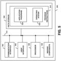
- Figure 5 is a simplified block diagram showing some of the components of an example computing device 500 that may include imaging components 524.
- Imaging components 524 may include one or more cameras or other types of image sensing elements (e.g., Fourier image capture arrays). Alternatively, an example computing device may lack such components and receive image information via some other means (e.g., via the internet or some other network or other communications interface).
- image sensing elements e.g., Fourier image capture arrays
- an example computing device may lack such components and receive image information via some other means (e.g., via the internet or some other network or other communications interface).
- computing device 500 may be a cellular mobile telephone (e.g., a smartphone), a video camera, a computer (such as a desktop, notebook, tablet, or handheld computer), a personal digital assistant (PDA), a wearable computing device, or some other type of device that may be equipped with imaging and/or image processing capabilities.
- computing device 500 may represent a physical image recording device, a particular physical hardware platform on which an image capture application operates in software, or other combinations of hardware and software that are configured to carry out image capture and/or image processing functions.
- computing device 500 may include a communication interface 502, a user interface 504, a processor 506, data storage 508, and imaging components 524, all of which may be communicatively linked together by a system bus, network, or other connection mechani sm 510.
- Communication interface 502 may function to allow computing device 500 to communicate, using analog or digital modulation of electric, magnetic, electromagnetic, optical, or other signals, with other devices, access networks, and/or transport networks.
- communication interface 502 may facilitate circuit-switched and/or packet-switched communication, such as plain old telephone service (POTS) communication and/or Internet protocol (IP) or other packetized communication.
- POTS plain old telephone service
- IP Internet protocol
- communication interface 502 may include a chipset and antenna arranged for wireless communication with a radio access network or an access point.
- communication interface 502 may take the form of or include a wireline interface, such as an Ethernet, Universal Serial Bus (USB), or High-Definition Multimedia Interface (HDMI) port.
- USB Universal Serial Bus
- HDMI High-Definition Multimedia Interface
- Communication interface 502 may also take the form of or include a wireless interface, such as a Wifi, BLUETOOTH ® , global positioning system (GPS), or wide-area wireless interface (e.g., WiMAX or 3GPP Long-Term Evolution (LTE)).
- a wireless interface such as a Wifi, BLUETOOTH ® , global positioning system (GPS), or wide-area wireless interface (e.g., WiMAX or 3GPP Long-Term Evolution (LTE)).
- GPS global positioning system
- LTE 3GPP Long-Term Evolution
- communication interface 502 may comprise multiple physical communication interfaces (e.g., a Wifi interface, a BLUETOOTH ® interface, and a wide-area wireless interface).
- communication interface 502 may function to allow computing device 500 to communicate, with other devices, remote servers, access networks, and/or transport networks.
- the communication interface 502 may function to transmit and/or receive an indication of image information, to transmit an indication of an image that has be generated using the methods described herein, or some other information.
- the computing device 500 could be a cellphone, digital camera, or other image capturing device and the remote system could be a computer, server, cloud computing system, or other system configured to perform the methods described herein.
- User interface 504 may function to allow computing device 500 to interact with a user, for example to receive input from and/or to provide output to the user.
- user interface 504 may include input components such as a keypad, keyboard, touch-sensitive or presence-sensitive panel, computer mouse, trackball, joystick, microphone, and so on.
- User interface 504 may also include one or more output components such as a display screen which, for example, may be combined with a presence-sensitive panel. The display screen may be based on CRT, LCD, and/or LED technologies, or other technologies now known or later developed.
- User interface 504 may also be configured to generate audible output(s), via a speaker, speaker jack, audio output port, audio output device, earphones, and/or other similar devices.
- user interface 504 may include a display that serves to present video or other images to a user (e.g., images generated using the imaging components 524 and/or generated according to the methods described herein). Additionally, user interface 504 may include one or more buttons, switches, knobs, and/or dials that facilitate the configuration and operation of the imaging components 524, the capturing of images and/or video streams using the imaging components 524, or to configure some other operation of the computing device 500. It may be possible that some or all of these buttons, switches, knobs, and/or dials are implemented as functions on a touch- or presence-sensitive panel.
- Processor 506 may comprise one or more general purpose processors - e.g., microprocessors - and/or one or more special purpose processors - e.g., digital signal processors (DSPs), graphics processing units (GPUs), floating point units (FPUs), network processors, or application-specific integrated circuits (ASICs).
- DSPs digital signal processors
- GPUs graphics processing units
- FPUs floating point units
- ASICs application-specific integrated circuits
- special purpose processors may be capable of image processing, image registration and/or scaling, and neural network computation, among other applications or functions.
- Data storage 508 may include one or more volatile and/or non-volatile storage components, such as magnetic, optical, flash, or organic storage, and may be integrated in whole or in part with processor 506.
- Data storage 508 may include removable and/or non-removable components.
- Processor 506 may be capable of executing program instructions 518 (e.g., compiled or non-compiled program logic and/or machine code) stored in data storage 508 to carry out the various functions described herein. Therefore, data storage 508 may include a non-transitory computer-readable medium, having stored thereon program instructions that, upon execution by computing device 500, cause computing device 500 to carry out any of the methods, processes, or functions disclosed in this specification and/or the accompanying drawings.
- program instructions 518 e.g., compiled or non-compiled program logic and/or machine code
- program instructions 518 may include an operating system 522 (e.g., an operating system kernel, device driver(s), and/or other modules) and one or more application programs 520 (e.g., image and/or video recording functions, image processing) installed on computing device 500.
- an operating system 522 e.g., an operating system kernel, device driver(s), and/or other modules
- application programs 520 e.g., image and/or video recording functions, image processing
- Application programs 520 may take the form of "apps" that could be downloadable to computing device 500 through one or more online application stores or application markets (via, e.g., the communication interface 502). However, application programs can also be installed on computing device 500 in other ways, such as via a web browser or through a physical interface (e.g., a USB port) of the computing device 500.
- portions of the methods described herein could be performed by different devices, according to an application.
- different devices of a system could have different amounts of computational resources (e.g., memory, processor cycles) and different information bandwidths for communication between the devices.
- a first device could be a cellphone or other audiovisual capture device that could transmit an image and/or video stream to another device or server that has the necessary computational resources to perform the methods described herein to the transmitted image information.
- Different portions of the methods described herein could be apportioned according to such considerations.
- Figure 6 is a flowchart of a method 600 for generating visible light images of a scene based on low-light visible image information detected from the scene (e.g., generated by an RGB visible light camera) and flash assisted invisible image information detected from the scene (e.g., generated by an additional camera that is sensitive to both the invisible wavelengths of the invisible flash as well as one or more visible wavelengths to facilitate image registration with the visible image information) that are improved relative to the acquired visible-wavelength image information detected from the scene with respect to noise level, contrast, sharpness, accuracy of representation of the contents of the scene, or some other measure of image quality.
- the method 600 includes illuminating a scene with light at a first invisible wavelength during a first period of time (610) by operating a flash to generate illumination at the first invisible wavelength. Additional illumination, at additional invisible wavelengths, may also be generated during the first period of time.
- the method 600 additionally includes, during the first period of time, obtaining image data for the scene (620).
- the obtained image data includes information indicative of red, green, and blue light received from the scene and information indicative of light received from the scene at the first invisible wavelength.
- the image data is obtained by operating multiple cameras to generate the image data. For example, a first camera could be operated to generate the red, green, and blue image data (e.g., the first camera is an RGB camera) while a second camera could be operated to generate the invisible wavelength image data, as well as additional visible-light image data to facilitate registration of the red, green, and blue image data with the invisible wavelength image data.
- Image data could be generated for additional invisible wavelengths (e.g., for an infrared wavelength and an ultraviolet wavelength, for two different infrared wavelengths).
- the method 600 additionally includes using the obtained image data to generate an improved visible-light image of the scene (630).
- This can include performing image registration to register the visible and invisible image information to each another.
- This can include using an artificial neural network, a bilateral filter, or some other method to combine the visible and invisible image information.
- This can include scaling one or the other of the visible and invisible image information based on the opposite image information.
- the method 600 could include additional elements or features.
- the visible-wavelength image information generated in the process of generating the invisible-wavelength image information could be used, in combination with corresponding-wavelength image information within the red, green, and blue image data, to generate a depth map for the scene.
- each step, block and/or communication may represent a processing of information and/or a transmission of information in accordance with example embodiments.
- Alternative embodiments are included within the scope of these example embodiments.
- functions described as steps, blocks, transmissions, communications, requests, responses, and/or messages may be executed out of order from that shown or discussed, including in substantially concurrent or in reverse order, depending on the functionality involved.
- more or fewer steps, blocks and/or functions may be used with any of the message flow diagrams, scenarios, and flow charts discussed herein, and these message flow diagrams, scenarios, and flow charts may be combined with one another, in part or in whole.
- a step or block that represents a processing of information may correspond to circuitry that can be configured to perform the specific logical functions of a herein-described method or technique.
- a step or block that represents a processing of information may correspond to a module, a segment, or a portion of program code (including related data).
- the program code may include one or more instructions executable by a processor for implementing specific logical functions or actions in the method or technique.
- the program code and/or related data may be stored on any type of computer-readable medium, such as a storage device, including a disk drive, a hard drive, or other storage media.
- the computer-readable medium may also include non-transitory computer-readable media such as computer-readable media that stores data for short periods of time like register memory, processor cache, and/or random access memory (RAM).
- the computer-readable media may also include non-transitory computer-readable media that stores program code and/or data for longer periods of time, such as secondary or persistent long term storage, like read only memory (ROM), optical or magnetic disks, and/or compact-disc read only memory (CD-ROM), for example.
- the computer-readable media may also be any other volatile or non-volatile storage systems.
- a computer-readable medium may be considered a computer-readable storage medium, for example, or a tangible storage device.
- a step or block that represents one or more information transmissions may correspond to information transmissions between software and/or hardware modules in the same physical device. However, other information transmissions may be between software modules and/or hardware modules in different physical devices.
Landscapes
- Engineering & Computer Science (AREA)
- Multimedia (AREA)
- Signal Processing (AREA)
- Physics & Mathematics (AREA)
- General Physics & Mathematics (AREA)
- Electromagnetism (AREA)
- Theoretical Computer Science (AREA)
- Studio Devices (AREA)
- Image Processing (AREA)
Description
- In low-light situations, photographs generated without supplemental illumination (e.g., a flash) can suffer from high noise or other negative effects. The use of a flash to momentarily illuminate a scene, in time with the imaging of the scene (e.g., by one or more cameras), can permit contents of the scene to be imaged more effectively. However, the use of a flash can cause irritation to humans and animals that are illuminated by the flash (e.g., by irritating their eyes, due to the eyes' having adapted to the lower illumination level absent the flash). Additionally, contents of the scene that are illuminated by the flash can appear washed-out, due to over-illumination by the flash.
- Additionally or alternatively, an exposure time can be increased and/or multiple images could be taken and later computationally combined in order to overcome some of the limitations inherent in low-light photography. However, these methods may exhibit significant blur due to motion of objects within the imaged scene and/or due to motion of the imaging device (e.g., a camera, a cellphone) relative to the scene.
- An aspect of the present disclosure relates to a device according to claim
- Another aspect of the present disclosure relates to a method according to claim 10.
- These as well as other aspects, advantages, and alternatives will become apparent to those of ordinary skill in the art by reading the following detailed description with reference where appropriate to the accompanying drawings. Further, it should be understood that the description provided in this summary section and elsewhere in this document is intended to illustrate the claimed subject matter by way of example and not by way of limitation.
-
-
Figure 1A depicts an example environment containing an example imaging device. -
Figure 1B depicts the example imaging device ofFigure 1A -
Figure 2 depicts a schematic of elements of two example imaging sensors. -
Figure 3 depicts a schematic of elements of an example imaging sensor. -
Figure 4A is a flowchart of a method, according to an example embodiment. -
Figure 4B is a flowchart of a method, according to an example embodiment. -
Figure 5 is a simplified block diagram showing some of the components of an example system. -
Figure 6 is a flowchart of a method, according to an example embodiment. - Examples of methods and systems are described herein. It should be understood that the words "exemplary," "example," and "illustrative," are used herein to mean "serving as an example, instance, or illustration." Any embodiment or feature described herein as "exemplary," "example," or "illustrative," is not necessarily to be construed as preferred or advantageous over other embodiments or features. Further, the exemplary embodiments described herein are not meant to be limiting. It will be readily understood that certain aspects of the disclosed systems and methods can be arranged and combined in a wide variety of different configurations.
- The present disclosure recites throughout a variety of wavelengths and/or ranges of wavelengths. As used herein, "visible wavelength(s)" refers to any wavelength of light that is generally visible by the human eye, i.e., wavelengths between 380 nanometers and 800 nanometers. "Invisible wavelength(s)" refers to any wavelength of light that is generally invisible or marginally visible by the human eye, i.e., wavelengths below 420 nanometers and wavelengths above 700 nanometers. "Infrared wavelength(s)" refers to wavelengths between 700 nanometers and 1 millimeter, while "near infrared wavelength(s)" refers to wavelengths between 700 nanometers and 1400 nanometers. "Ultraviolet wavelength(s)" refers to wavelengths between 10 nanometers and 420 nanometers, while "near infrared wavelength(s)" refers to wavelengths between 300 nanometers and 420 nanometers. "Red wavelength(s)" refers to wavelengths between 500 nanometers and 750 nanometers, "green wavelength(s)" refers to wavelengths between 450 nanometers and 630 nanometers, and "blue wavelength(s)" refers to wavelengths between 400 nanometers and 500 nanometers.
- Low light conditions can lead to difficulty in photography. While a flash can be used to illuminate a scene of interest, the resulting image can be washed-out and unnatural-looking, due to the flash only illuminating portions of the imaged scene. Additionally, the light from a flash can be irritating, particularly to people whose eyes have adapted to the low light levels that necessitated the flash. Additionally or alternatively, a longer exposure duration, or multiple short exposures, could be used to image a scene in order to reduce noise in the generated image. However, movement of objects within the scene and/or of the camera relative to the scene can cause blurring when the camera is operated in such a manner.
- In order to alleviate these issues, invisible wavelengths of light (e.g., infrared, ultraviolet) can be used to illuminate a scene to be imaged. The invisible flash avoids irritating people in the scene while providing illumination to facilitate imaging the scene. Image information for the scene, at the invisible wavelength of the invisible flash, can then be used to augment or improve visible-light image information (e.g., red, green, and blue images) simultaneously taken of the scene. The invisible image information can include information about the structure of contents of the image (e.g., the size, shape, texture, and location of people, objects, or other contents within the scene) while the visible image information can provide information about the chroma or coloration of the contents of the image, as well as some information about the structure of the contents of the image. Additional invisible flashes, at respective additional invisible wavelengths, could be used to provide additional invisible image information for the scene.
- The visible and invisible image information could be combined in a variety of ways in order to generate an improved image of the scene, e.g., an image that approximates an image of the scene had the scene been illuminated by daylight. This could be effected by, e.g., scaling the visible image information according to a magnitude and/or gradient present in the invisible image information and/or using the invisible image information to inform the phase and magnitude of the output image information while using the visible image information to inform the chrome of the output image (e.g., by applying a bilateral filter to the invisible image information to "colorize" the invisible image information according to the visible image information). In the invention, an artificial neural network (e.g., a convolutional neural network) is used to combine the visible and invisible image information (e.g., to colorize the invisible image information based on the visible image information) and/or to "clean up" an already-combined image.
- The visible and invisible image information for a scene could be acquired in a variety of ways. In some examples not according to the claims, a single camera or other image sensor could be configured to image visible light at multiple wavelengths (e.g., red, green, and blue wavelengths) and invisible light at one or more wavelengths (e.g., an infrared wavelength, a near infrared wavelength, an ultraviolet wavelength, and/or a near ultraviolet wavelength). In an embodiment, a camera could include a Bayer filter having green, red, blue, and invisible (e.g., infrared) filters disposed on respective sets of pixels. In the invention, multiple cameras are used to generate the visible and invisible image information. For example, a device could include a first camera configured to image multiple visible-light wavelengths (e.g., red, green, and blue wavelengths) and a second camera configured to image at least one visible-light wavelength corresponding to one of the wavelengths imaged by the first camera (e.g., a green wavelength) and at least one invisible wavelength (e.g., one or more of an infrared, near infrared, ultraviolet, and/or near ultraviolet wavelength(s)). The first and second cameras could be operated to image a scene concurrently (e.g., during the period of time when the scene is being illuminated by an invisible flash) and the resulting first and second images could be registered to each other (e.g., based on correspondences between the visible-light image information generated by both of the cameras) and the registered images could then be used to generate an improved image of the scene, as described herein.
- It should be understood that the above embodiments, and other embodiments described herein, are provided for explanatory purposes, and are not intended to be limiting.
- As described herein, image information about a scene generated at one or more invisible wavelengths, while illuminating the scene at the one or more invisible wavelengths (e.g., using one or more flashes), can be used to improve a visible-light image taken of the scene. Such improvement can be related to statistical correlations between the magnitude, gradient, or other image information present at the invisible wavelength(s) for natural scenes and image information at visible wavelengths for those natural scenes. For example, the invisible-wavelength image(s) could provide relatively low-noise, high-contrast information about edges or other image phase information for a scene (e.g., the shapes, sizes, and location of objects, textures, or other contents of the scene), due in part to the illumination of the scene at corresponding invisible wavelengths. Contemporaneously-acquired visible-wavelength information could provide information about the visible-light chroma of the contents of the scene, and known relationships between the visible and invisible image contents of natural scenes could be used to combine the visible and invisible image information for the scene in order to generate an improved visible-light image of the scene (i.e., an image that accurately represents how the scene would have looked had it been illuminated by a flash, by sunlight, or by some other source of illumination)
- A device (or system of devices) may be configured in a variety of ways to generate such imaging information (i.e., imaging information at a number of visible wavelengths and a number of invisible wavelengths) while illuminating a scene at one or more invisible (e.g., near infrared, infrared, ultraviolet, near ultraviolet) wavelengths. In some examples, the device could include a single hyperspectral camera component configured to generate image data at the specified visible wavelength and a second one for the invisible wavelengths. In another example, the device could include a camera for each of the wavelengths to be imaged, coupled together with a beamsplitter or other optical elements such that each of the cameras receives light at a respective visible or invisible wavelength. In yet another example, the device could include a number of cameras, with each camera configured to image a respective set of visible and/or invisible wavelengths (e.g., a first camera configured to image red, green, and blue wavelengths, and a second camera configured to image one of the preceding visible wavelengths (e.g., green) and one or more invisible wavelengths).
-
Figures 1A and 1B illustrate anexample device 110 configured to image ascene 100 according to the methods described herein. Thedevice 110 could take the form of a cellphone, a tablet computer, a portable video recording device, a camera, or some other form factor. Thedevice 110 includes afirst camera 115a and asecond camera 115b and afirst flash 125a and asecond flash 125b. Theflashes flashes scene 100 at respective sets of wavelengths. For example, thefirst camera 115a could generate image information at red, green, and blue wavelengths and thesecond camera 115b could generate image information at the green wavelength and at one or more invisible wavelengths corresponding to the wavelength(s) of invisible illumination generated by the flash(es) 125a, 125b. - The wavelengths detected by each of two (or more) cameras of a device could be specified to provide a variety of benefits. For example, one of the cameras could be a standard visible-light camera (e.g., an RGB camera) such that the system can operate in a normal visible-light mode. Additionally, any visible-plus-invisible image data generated using such a system could be used to generate visible-light images using standard low-light image processing techniques (e.g., by applying such image processing techniques to the visible-light image data generated using the visible-light camera).
- Further, the use of off-the-shelf visible-light cameras can provide economies of scale. These economies of scale could also be accessed by modifying a visible-light camera (e.g., by adding and/or subtracting one or more wavelength-selective filters to/from such a camera) in order to operate the modified camera to detect image data for one or more invisible wavelengths of light. For example, an infrared filter could be removed from such a visible-light camera and/or a red filter could be added to such a camera such that the "red" pixels of such a modified camera could be operated to generate image data at an infrared wavelength. Additionally or alternatively, an ultraviolet filter could be removed from such a visible-light camera and/or a blue filter could be added to such a camera such that the "blue" pixels of such a modified camera could be operated to generate image data at an ultraviolet wavelength.
-
Figure 2 illustrates an example arrangement of pixels of two cameras. The first camera (e.g., 115a) has afirst pixel arrangement 200a that includes pixels sensitive to red ("R"), green ("G"), and blue ("B") wavelengths of light, respectively. This selective sensitivity could be effected, in the first camera, by disposing respectively sets of light filters on or otherwise proximate to the pixels of the first camera, such that light of the corresponding wavelength is permitted to reach each pixel. Additional light filters (e.g., a filter configured to block light at infrared wavelengths and/or a filter configured to block ultraviolet wavelengths) could be applied to light that is received by all of the pixels (e.g., such a filter could be applied at an aperture of the first camera) to improve the wavelength-specificity of each of the sets of pixels. - The second camera (e.g., 115b) has a
second pixel arrangement 200b that includes pixels sensitive to a first visible wavelength (a green wavelength, "G"), and two invisible wavelengths (an infrared wavelength, "IR," and an ultraviolet wavelength, "UV"). This selective sensitivity could be effected, in the second camera, by disposing respectively sets of light filters on or otherwise proximate to the pixels of the second camera, such that light of the corresponding wavelength is permitted to reach each pixel. As noted above, the second camera could be an off-the-shelf visible-light camera that has been modified (e.g., by removal/additional of light filters to the aperture or other locations of the second camera) to provide the described visible and invisible image information. In such examples, the individual-pixel filters could permit passage of more light at visible wavelengths (e.g., more blue light than ultraviolet light to the "UV' pixels, more red light than infrared light to the "IR" pixels) that, in combination with additional filters (e.g., filters that block blue, red, or other visible wavelengths of light), render the corresponding pixels selectively sensitive to the corresponding invisible wavelengths of light. - The illustrated correspondence between the green pixels of the first and
second patterns - Note that the illustrated presence of green pixels in both the first and
second patterns - Image information generated as described herein for a scene, that includes low-light visible-wavelength image information about the scene as well as image information at one or more invisible wavelengths for the scene while the scene is illuminated (e.g., by a flash) at the one or more invisible wavelengths, can be used in a variety of ways to generate a visible-light image for the scene that is improved relative to the visible-wavelength image information detected from the scene. Such an improved visible-light image could be improved relative to the detected visible-light image with respect to a variety of image properties, e.g., an overall noise level of the image, a contrast or sharpness of the image, an accuracy of the image with respect to edges, textures, or other sharp contents of the image, with respect to aesthetic considerations, or with respect to some other metric of interest.
- In the invention, the visible-wavelength image information and the invisible-wavelength image information are combined by applying the sets of image information to an artificial neural network (e.g., a convolutional neural network). Additionally one of the sets of image information (e.g., the visible-light image information) could be used to scale, augment, or otherwise modify the other set of image information (e.g., the invisible-light image information) according to known statistical relationships between the optical properties of contents of natural scenes at the visible and invisible wavelengths.
- An example of such an
image processing flow 400a is depicted inFigure 4A . The input information includes visible-wavelength image information ("VISIBLE IMAGE DATA") generated, e.g., by a camera sensitive to red, green, and blue wavelengths and invisible-wavelength image ("INVISIBLE IMAGE DATA") generated, e.g., by a camera sensitive to one or more invisible wavelengths of light. - The first step of the image processing flow is to register the visible and invisible image information together ("REGISTER IMAGE DATA") such that the images correspond. This can include, in examples wherein the camera or other image sensor that generated the invisible image information also generated visible-wavelength image information, determining a correspondence between the visible-wavelength image information and additional visible-wavelength image information generated using the same image sensor as that used to generate the invisible-wavelength image information. For example, determining a correspondence between a green channel of the visible-wavelength image information (generated, e.g., by the
first camera 115a) and a green channel generated by a camera that is also used to generate the invisible-wavelength image information (e.g., thesecond camera 115b). The determined correspondence can then be used to warp one of the sets of image information to the other, to warp them toward some intermediary structure, or to otherwise register the visible and invisible image information to each other. In some examples, the visible image information can be warped or otherwise registered to correspond to the invisible image information due to the likely higher image contrast, lower image noise, or other properties of the invisible image information due to the invisible image information having been generated while the scene is illuminated with light at a corresponding invisible wavelength(s) (e.g., by a flash that emits light at such invisible wavelength(s)). - Note that, in examples not all according to the claims wherein the visible and invisible image information are generated by a single camera or are otherwise generated via a process such that the visible and invisible image information are already registered to each other, the image registration step may be omitted.
- The registered visible-light image information is then used to scale the invisible-light image information and/or the invisible-light image information is used to scale the visible-light image information to generate scaled visible-light image. This scaled visible-light image represents an image of a scene that is improved relative to the visible light image information alone (e.g., with respect to image noise level, contrast, sharpness, preservation of edges, textures, or other sharp features within the image). This scaling can take into account the fact that the visible-light image information likely has superior information about the visible-light chroma of contents of the scene while the invisible-light image information, having the benefit of illumination by an invisible-wavelength flash, is likely to have superior information regarding the shape, location, texture, edges, or other image-phase-related contents of an image of the scene.
- Accordingly, scaling the image data can include scaling one or both of the magnitude or gradient of the invisible image information according to each wavelength of the visible image information. This scaling can include using a bilateral filter to combine the invisible image information and the visible image information. For example, the bilateral filter could be applied using a cost function that includes a first term related to sharp features (e.g., edges, local self-similarity) within the magnitude and/or gradient of the invisible image information and a second term related to the chroma of the visible image information (e.g., a regional average chroma, to compensate for noise in the visible image information).
- The scaled visible-light image can then be used, e.g., by being presented on a screen of a cellphone or saved to an online photo album. Additionally or alternatively, post-processing could be applied to further improve the scaled visible-light image. For example, a de-noising process, a contrast-enhancement, or some other filtering could be applied to the scaled visible-light image. In the invention, an artificial neural network (ANN) (e.g., a convolutional artificial neural network) is applied to post-process the scaled visible-light image (shown in
Figure 4A as "ANN FILTER"). Such an artificial neural network filter could be trained using a training data set that includes very long-exposure visible-light images of a variety of natural scenes as the "ground truth" outputs and corresponding sets of low-light visible light images of the scenes taken contemporaneously with invisible-flash-illuminated invisible light images of the scenes. The preceding image processing steps (e.g., image registration, scaling) could then be applied to the sets of low-light visible light images and invisible images in order to generate the input images for training the artificial neural network. - In the invention, the visible image information and the invisible image information are combined directly, by being applied to an artificial neural network trained to perform such a task. This is illustrated in
Figure 4B , which shows an example of such animage processing flow 400b. - The input information includes visible-wavelength image information ("VISIBLE IMAGE DATA") generated, e.g., by a camera sensitive to red, green, and blue wavelengths and invisible-wavelength image ("INVISIBLE IMAGE DATA") generated, e.g., by a camera sensitive to one or more invisible wavelengths of light. The
image processing flow 400b includes registering the visible and invisible image information together ("REGISTER IMAGE DATA") such that the images correspond. In examples wherein the image data is already registered, this step may be omitted. The registered visible and invisible image information is then combined, by the artificial neural network ("ANN COMBINE") to generate an improved visible light image. - Such an artificial neural network filter could be trained using a training data set that includes very long-exposure visible-light images of a variety of natural scenes as the "ground truth" outputs and corresponding sets of low-light visible light images of the scenes taken contemporaneously with invisible-flash-illuminated invisible light images of the scenes. The preceding image processing steps (e.g., image registration) could then be applied to the sets of low-light visible light images and invisible images in order to generate the input images for training the artificial neural network.
- Computational functions (e.g., functions to obtain visible and/or invisible image information for a scene, to combine or otherwise image-process such image information to generate improved visible-light images of a scene, to generate a depth map for a scene)) described herein may be performed by one or more computing systems. Such a computing system may be integrated into or take the form of a computing device, such as a mobile phone, tablet computer, laptop computer, server, home automation element, standalone video capture and processing device, cloud computing network, and/or programmable logic controller. For purposes of example,
Figure 5 is a simplified block diagram showing some of the components of anexample computing device 500 that may includeimaging components 524.Imaging components 524 may include one or more cameras or other types of image sensing elements (e.g., Fourier image capture arrays). Alternatively, an example computing device may lack such components and receive image information via some other means (e.g., via the internet or some other network or other communications interface). - By way of example and without limitation,
computing device 500 may be a cellular mobile telephone (e.g., a smartphone), a video camera, a computer (such as a desktop, notebook, tablet, or handheld computer), a personal digital assistant (PDA), a wearable computing device, or some other type of device that may be equipped with imaging and/or image processing capabilities. It should be understood thatcomputing device 500 may represent a physical image recording device, a particular physical hardware platform on which an image capture application operates in software, or other combinations of hardware and software that are configured to carry out image capture and/or image processing functions. - As shown in
Figure 5 ,computing device 500 may include acommunication interface 502, auser interface 504, aprocessor 506,data storage 508, andimaging components 524, all of which may be communicatively linked together by a system bus, network, or other connection mechanism 510. -
Communication interface 502 may function to allowcomputing device 500 to communicate, using analog or digital modulation of electric, magnetic, electromagnetic, optical, or other signals, with other devices, access networks, and/or transport networks. Thus,communication interface 502 may facilitate circuit-switched and/or packet-switched communication, such as plain old telephone service (POTS) communication and/or Internet protocol (IP) or other packetized communication. For instance,communication interface 502 may include a chipset and antenna arranged for wireless communication with a radio access network or an access point. Also,communication interface 502 may take the form of or include a wireline interface, such as an Ethernet, Universal Serial Bus (USB), or High-Definition Multimedia Interface (HDMI) port.Communication interface 502 may also take the form of or include a wireless interface, such as a Wifi, BLUETOOTH®, global positioning system (GPS), or wide-area wireless interface (e.g., WiMAX or 3GPP Long-Term Evolution (LTE)). However, other forms of physical layer interfaces and other types of standard or proprietary communication protocols may be used overcommunication interface 502. Furthermore,communication interface 502 may comprise multiple physical communication interfaces (e.g., a Wifi interface, a BLUETOOTH® interface, and a wide-area wireless interface). - In some embodiments,
communication interface 502 may function to allowcomputing device 500 to communicate, with other devices, remote servers, access networks, and/or transport networks. For example, thecommunication interface 502 may function to transmit and/or receive an indication of image information, to transmit an indication of an image that has be generated using the methods described herein, or some other information. For example, thecomputing device 500 could be a cellphone, digital camera, or other image capturing device and the remote system could be a computer, server, cloud computing system, or other system configured to perform the methods described herein. -
User interface 504 may function to allowcomputing device 500 to interact with a user, for example to receive input from and/or to provide output to the user. Thus,user interface 504 may include input components such as a keypad, keyboard, touch-sensitive or presence-sensitive panel, computer mouse, trackball, joystick, microphone, and so on.User interface 504 may also include one or more output components such as a display screen which, for example, may be combined with a presence-sensitive panel. The display screen may be based on CRT, LCD, and/or LED technologies, or other technologies now known or later developed.User interface 504 may also be configured to generate audible output(s), via a speaker, speaker jack, audio output port, audio output device, earphones, and/or other similar devices. - In some embodiments,
user interface 504 may include a display that serves to present video or other images to a user (e.g., images generated using theimaging components 524 and/or generated according to the methods described herein). Additionally,user interface 504 may include one or more buttons, switches, knobs, and/or dials that facilitate the configuration and operation of theimaging components 524, the capturing of images and/or video streams using theimaging components 524, or to configure some other operation of thecomputing device 500. It may be possible that some or all of these buttons, switches, knobs, and/or dials are implemented as functions on a touch- or presence-sensitive panel. -
Processor 506 may comprise one or more general purpose processors - e.g., microprocessors - and/or one or more special purpose processors - e.g., digital signal processors (DSPs), graphics processing units (GPUs), floating point units (FPUs), network processors, or application-specific integrated circuits (ASICs). In some instances, special purpose processors may be capable of image processing, image registration and/or scaling, and neural network computation, among other applications or functions.Data storage 508 may include one or more volatile and/or non-volatile storage components, such as magnetic, optical, flash, or organic storage, and may be integrated in whole or in part withprocessor 506.Data storage 508 may include removable and/or non-removable components. -
Processor 506 may be capable of executing program instructions 518 (e.g., compiled or non-compiled program logic and/or machine code) stored indata storage 508 to carry out the various functions described herein. Therefore,data storage 508 may include a non-transitory computer-readable medium, having stored thereon program instructions that, upon execution bycomputing device 500,cause computing device 500 to carry out any of the methods, processes, or functions disclosed in this specification and/or the accompanying drawings. - By way of example,
program instructions 518 may include an operating system 522 (e.g., an operating system kernel, device driver(s), and/or other modules) and one or more application programs 520 (e.g., image and/or video recording functions, image processing) installed oncomputing device 500. -
Application programs 520 may take the form of "apps" that could be downloadable tocomputing device 500 through one or more online application stores or application markets (via, e.g., the communication interface 502). However, application programs can also be installed oncomputing device 500 in other ways, such as via a web browser or through a physical interface (e.g., a USB port) of thecomputing device 500. - In some examples, portions of the methods described herein could be performed by different devices, according to an application. For example, different devices of a system could have different amounts of computational resources (e.g., memory, processor cycles) and different information bandwidths for communication between the devices. For example, a first device could be a cellphone or other audiovisual capture device that could transmit an image and/or video stream to another device or server that has the necessary computational resources to perform the methods described herein to the transmitted image information. Different portions of the methods described herein could be apportioned according to such considerations.
-
Figure 6 is a flowchart of amethod 600 for generating visible light images of a scene based on low-light visible image information detected from the scene (e.g., generated by an RGB visible light camera) and flash assisted invisible image information detected from the scene (e.g., generated by an additional camera that is sensitive to both the invisible wavelengths of the invisible flash as well as one or more visible wavelengths to facilitate image registration with the visible image information) that are improved relative to the acquired visible-wavelength image information detected from the scene with respect to noise level, contrast, sharpness, accuracy of representation of the contents of the scene, or some other measure of image quality. Themethod 600 includes illuminating a scene with light at a first invisible wavelength during a first period of time (610) by operating a flash to generate illumination at the first invisible wavelength. Additional illumination, at additional invisible wavelengths, may also be generated during the first period of time. - The
method 600 additionally includes, during the first period of time, obtaining image data for the scene (620). The obtained image data includes information indicative of red, green, and blue light received from the scene and information indicative of light received from the scene at the first invisible wavelength. The image data is obtained by operating multiple cameras to generate the image data. For example, a first camera could be operated to generate the red, green, and blue image data (e.g., the first camera is an RGB camera) while a second camera could be operated to generate the invisible wavelength image data, as well as additional visible-light image data to facilitate registration of the red, green, and blue image data with the invisible wavelength image data. Image data could be generated for additional invisible wavelengths (e.g., for an infrared wavelength and an ultraviolet wavelength, for two different infrared wavelengths). - The
method 600 additionally includes using the obtained image data to generate an improved visible-light image of the scene (630). This can include performing image registration to register the visible and invisible image information to each another. This can include using an artificial neural network, a bilateral filter, or some other method to combine the visible and invisible image information. This can include scaling one or the other of the visible and invisible image information based on the opposite image information. - The
method 600 could include additional elements or features. For example, the visible-wavelength image information generated in the process of generating the invisible-wavelength image information could be used, in combination with corresponding-wavelength image information within the red, green, and blue image data, to generate a depth map for the scene. - The above detailed description describes various features and functions of the disclosed systems, devices, and methods with reference to the accompanying figures. In the figures, similar symbols typically identify similar components, unless context indicates otherwise. The illustrative embodiments described in the detailed description, figures, and claims are not meant to be limiting. Other embodiments can be utilized, and other changes can be made, without departing from the scope of the subject matter presented in the claims. It will be readily understood that the aspects of the present disclosure, as generally described herein, and illustrated in the figures, can be arranged, substituted, combined, separated, and designed in a wide variety of different configurations, all of which are explicitly contemplated herein.
- With respect to any or all of the message flow diagrams, scenarios, and flowcharts in the figures and as discussed herein, each step, block and/or communication may represent a processing of information and/or a transmission of information in accordance with example embodiments. Alternative embodiments are included within the scope of these example embodiments. In these alternative embodiments, for example, functions described as steps, blocks, transmissions, communications, requests, responses, and/or messages may be executed out of order from that shown or discussed, including in substantially concurrent or in reverse order, depending on the functionality involved. Further, more or fewer steps, blocks and/or functions may be used with any of the message flow diagrams, scenarios, and flow charts discussed herein, and these message flow diagrams, scenarios, and flow charts may be combined with one another, in part or in whole.
- A step or block that represents a processing of information may correspond to circuitry that can be configured to perform the specific logical functions of a herein-described method or technique. Alternatively or additionally, a step or block that represents a processing of information may correspond to a module, a segment, or a portion of program code (including related data). The program code may include one or more instructions executable by a processor for implementing specific logical functions or actions in the method or technique. The program code and/or related data may be stored on any type of computer-readable medium, such as a storage device, including a disk drive, a hard drive, or other storage media.
- The computer-readable medium may also include non-transitory computer-readable media such as computer-readable media that stores data for short periods of time like register memory, processor cache, and/or random access memory (RAM). The computer-readable media may also include non-transitory computer-readable media that stores program code and/or data for longer periods of time, such as secondary or persistent long term storage, like read only memory (ROM), optical or magnetic disks, and/or compact-disc read only memory (CD-ROM), for example. The computer-readable media may also be any other volatile or non-volatile storage systems. A computer-readable medium may be considered a computer-readable storage medium, for example, or a tangible storage device.
- Moreover, a step or block that represents one or more information transmissions may correspond to information transmissions between software and/or hardware modules in the same physical device. However, other information transmissions may be between software modules and/or hardware modules in different physical devices.
- While various aspects and embodiments have been disclosed herein, other aspects and embodiments will be apparent to those skilled in the art. The various aspects and embodiments disclosed herein are for purposes of illustration and are not intended to be limiting, with the true scope being indicated by the following claims.
Claims (15)
- A device comprising:a first camera (115a),a second camera (115b), anda controller operably coupled to the first camera and the second camera, wherein the controller comprises at least one processor programmed to perform controller operations comprising:simultaneously operating:the first camera, to generate a visible light image of a scene based on light at a visible wavelength;the second camera to generate an invisible light image of the scene based on light at an invisible wavelength; anda flash (125a, 125b), to emit light at the invisible wavelength; and characterized byapplying visible image information and invisible image information to an artificial neural network to generate an enhanced visible light image, the visible image information associated with the visible light image, and the invisible image information associated with the invisible light image.
- The device of claim 1, wherein the artificial neural network is trained using a training data set that comprises:long-exposure visible light images of a plurality of natural scenes;low-light visible light images of the plurality natural scenes; andinvisible-flash-illuminated invisible light images of the plurality of natural scenes that are taken contemporaneously with the low-light visible light images.
- The device of claim 2, wherein the long-exposure visible light images are ground truth outputs of the training data set.
- The device of claim 1, wherein the artificial neural network comprises a convolutional artificial neural network.
- The device of claim 1, wherein the invisible wavelength comprises an infrared wavelength.
- The device of claim 1, wherein the invisible wavelength comprises an ultraviolet wavelength.
- The device of claim 1, wherein the invisible image information comprises structural information of content in the invisible light image.
- The device of claim 7 wherein the structural information comprises at least one of a size of the content, a shape of the content, a texture of a content, or a location of the content.
- The device of claim 1, wherein the visible image information comprises coloration information of content in the visible light image.
- A method comprising:operating, at a controller, a first camera (115a) to generate a visible light image of a scene based on light at a visible wavelength;operating a second camera (115b) to generate an invisible light image of the scene based on light at an invisible wavelength;operating a flash (125a, 125b) to emit light at the invisible wavelength, the flash, the second camera and the first camera operating simultaneously; and characterized byapplying visible image information and invisible image information to an artificial neural network to generate an enhanced visible light image, the visible image information associated with the visible light image, and the invisible image information associated with the invisible light image.
- The method of claim 10, further comprising, prior to applying the visible image information and the invisible image information to the artificial neural network:
training the artificial neural network using a training data set that comprises:long-exposure visible light images of a plurality of natural scenes; low-light visible light images of the plurality natural scenes; andinvisible-flash-illuminated invisible light images of the plurality of natural scenes that are taken contemporaneously with the low-light visible light images. - The method of claim 11, wherein the long-exposure visible light images are ground truth outputs of the training data set.
- The method of claim 10, wherein the artificial neural network comprises a convolutional artificial neural network.
- The method of claim 10, wherein the invisible wavelength comprises an infrared wavelength or an ultraviolet wavelength.
- A device comprising:
a controller comprising at least one processor programmed to perform controller operations of a method according to any of claims 10 - 14.
Applications Claiming Priority (2)
| Application Number | Priority Date | Filing Date | Title |
|---|---|---|---|
| US16/120,666 US11039122B2 (en) | 2018-09-04 | 2018-09-04 | Dark flash photography with a stereo camera |
| PCT/US2019/045208 WO2020050941A1 (en) | 2018-09-04 | 2019-08-06 | Dark flash photography with a stereo camera |
Publications (2)
| Publication Number | Publication Date |
|---|---|
| EP3844567A1 EP3844567A1 (en) | 2021-07-07 |
| EP3844567B1 true EP3844567B1 (en) | 2025-01-15 |
Family
ID=67660828
Family Applications (1)
| Application Number | Title | Priority Date | Filing Date |
|---|---|---|---|
| EP19755750.7A Active EP3844567B1 (en) | 2018-09-04 | 2019-08-06 | Dark flash photography with a stereo camera |
Country Status (4)
| Country | Link |
|---|---|
| US (2) | US11039122B2 (en) |
| EP (1) | EP3844567B1 (en) |
| CN (1) | CN112654924B (en) |
| WO (1) | WO2020050941A1 (en) |
Families Citing this family (5)
| Publication number | Priority date | Publication date | Assignee | Title |
|---|---|---|---|---|
| US11039122B2 (en) | 2018-09-04 | 2021-06-15 | Google Llc | Dark flash photography with a stereo camera |
| US10708557B1 (en) * | 2018-12-14 | 2020-07-07 | Lyft Inc. | Multispectrum, multi-polarization (MSMP) filtering for improved perception of difficult to perceive colors |
| CN114830627B (en) | 2020-11-09 | 2024-07-09 | 谷歌有限责任公司 | Imaging system and method for relighting visible light images |
| JP2023104713A (en) * | 2022-01-18 | 2023-07-28 | キヤノン株式会社 | IMAGE PROCESSING DEVICE, CONTROL METHOD FOR IMAGE PROCESSING DEVICE, AND PROGRAM |
| JP7442848B2 (en) * | 2022-03-30 | 2024-03-05 | 華晋グローバル株式会社 | Imaging device and method of controlling the imaging device |
Family Cites Families (17)
| Publication number | Priority date | Publication date | Assignee | Title |
|---|---|---|---|---|
| JP3800052B2 (en) | 2001-08-20 | 2006-07-19 | ソニー株式会社 | Still image capturing apparatus and method |
| US7454136B2 (en) * | 2005-07-28 | 2008-11-18 | Mitsubishi Electric Research Laboratories, Inc. | Method and apparatus for acquiring HDR flash images |
| US9354490B2 (en) | 2009-01-09 | 2016-05-31 | New York University | Method, computer-accessible, medium and systems for facilitating dark flash photography |
| JP5528173B2 (en) | 2010-03-31 | 2014-06-25 | キヤノン株式会社 | Image processing apparatus, imaging apparatus, and image processing program |
| US8891822B2 (en) * | 2012-04-10 | 2014-11-18 | Hewlett-Packard Development Company, L.P. | System and method for script and orientation detection of images using artificial neural networks |
| US10268885B2 (en) * | 2013-04-15 | 2019-04-23 | Microsoft Technology Licensing, Llc | Extracting true color from a color and infrared sensor |
| US9392262B2 (en) * | 2014-03-07 | 2016-07-12 | Aquifi, Inc. | System and method for 3D reconstruction using multiple multi-channel cameras |
| US9516295B2 (en) | 2014-06-30 | 2016-12-06 | Aquifi, Inc. | Systems and methods for multi-channel imaging based on multiple exposure settings |
| CN104702832B (en) * | 2015-03-31 | 2018-07-31 | 汕头市新视界电子有限公司 | A kind of imaging method and its equipment of the camera shooting of automobile safety monitoring |
| CN104883500A (en) * | 2015-05-05 | 2015-09-02 | 青岛海信移动通信技术股份有限公司 | Camera shooting device and control method thereof |
| EP3094082A1 (en) * | 2015-05-13 | 2016-11-16 | AIM Sport Vision AG | Digitally overlaying an image with another image |
| US10708573B2 (en) * | 2016-01-04 | 2020-07-07 | Occipital, Inc. | Apparatus and methods for three-dimensional sensing |
| US10770505B2 (en) * | 2017-04-05 | 2020-09-08 | Intel Corporation | Per-pixel performance improvement for combined visible and ultraviolet image sensor arrays |
| JP7027737B2 (en) * | 2017-09-05 | 2022-03-02 | ソニーグループ株式会社 | Image processing equipment, image processing method, and program |
| WO2019067193A1 (en) * | 2017-09-28 | 2019-04-04 | Apple Inc. | Nighttime sensing |
| CN107566753A (en) * | 2017-09-29 | 2018-01-09 | 努比亚技术有限公司 | Method, photo taking and mobile terminal |
| US11039122B2 (en) | 2018-09-04 | 2021-06-15 | Google Llc | Dark flash photography with a stereo camera |
-
2018
- 2018-09-04 US US16/120,666 patent/US11039122B2/en active Active
-
2019
- 2019-08-06 CN CN201980057934.XA patent/CN112654924B/en active Active
- 2019-08-06 WO PCT/US2019/045208 patent/WO2020050941A1/en not_active Ceased
- 2019-08-06 EP EP19755750.7A patent/EP3844567B1/en active Active
-
2021
- 2021-05-17 US US17/322,216 patent/US11490070B2/en active Active
Also Published As
| Publication number | Publication date |
|---|---|
| CN112654924A (en) | 2021-04-13 |
| US20210274151A1 (en) | 2021-09-02 |
| US11490070B2 (en) | 2022-11-01 |
| CN112654924B (en) | 2023-01-13 |
| US11039122B2 (en) | 2021-06-15 |
| EP3844567A1 (en) | 2021-07-07 |
| WO2020050941A1 (en) | 2020-03-12 |
| US20200077076A1 (en) | 2020-03-05 |
Similar Documents
| Publication | Publication Date | Title |
|---|---|---|
| US11490070B2 (en) | Dark flash photography with a stereo camera | |
| US9591237B2 (en) | Automated generation of panning shots | |
| US11978225B2 (en) | Depth determination for images captured with a moving camera and representing moving features | |
| EP3692500B1 (en) | Estimating depth using a single camera | |
| US9117134B1 (en) | Image merging with blending | |
| US11113832B2 (en) | Aperture supervision for single-view depth prediction | |
| US9918065B2 (en) | Depth-assisted focus in multi-camera systems | |
| US9253375B2 (en) | Camera obstruction detection | |
| CN107211100B (en) | Method and apparatus for motion deblurring of images | |
| CN110557584B (en) | Image processing method and device, and computer readable storage medium | |
| JP7425188B2 (en) | Focal deblurring and depth estimation using dual-pixel image data | |
| CN113454981A (en) | Techniques for multi-exposure fusion of multiple image frames based on convolutional neural network and for deblurring multiple image frames | |
| US20230033956A1 (en) | Estimating depth based on iris size | |
| US20150063694A1 (en) | Techniques for combining images with varying brightness degrees | |
| US20140176731A1 (en) | Determining Image Alignment Failure | |
| JP7223117B2 (en) | Super-resolution using natural hand-held motion applied to the user device | |
| US20200082508A1 (en) | Information processing method, information processing apparatus, and recording medium | |
| US11205064B1 (en) | Measuring quality of depth images in real time | |
| US20190220954A1 (en) | Apparatus, method, and computer program code for producing composite image | |
| WO2023136822A1 (en) | Machine learning models for example-guided image inpainting | |
| CN112422825A (en) | Intelligent photographing method, device, equipment and computer readable medium |
Legal Events
| Date | Code | Title | Description |
|---|---|---|---|
| STAA | Information on the status of an ep patent application or granted ep patent |
Free format text: STATUS: UNKNOWN |
|
| STAA | Information on the status of an ep patent application or granted ep patent |
Free format text: STATUS: THE INTERNATIONAL PUBLICATION HAS BEEN MADE |
|
| STAA | Information on the status of an ep patent application or granted ep patent |
Free format text: STATUS: REQUEST FOR EXAMINATION WAS MADE |
|
| PUAI | Public reference made under article 153(3) epc to a published international application that has entered the european phase |
Free format text: ORIGINAL CODE: 0009012 |
|
| 17P | Request for examination filed |
Effective date: 20210401 |
|
| AK | Designated contracting states |
Kind code of ref document: A1 Designated state(s): AL AT BE BG CH CY CZ DE DK EE ES FI FR GB GR HR HU IE IS IT LI LT LU LV MC MK MT NL NO PL PT RO RS SE SI SK SM TR |
|
| DAV | Request for validation of the european patent (deleted) | ||
| DAX | Request for extension of the european patent (deleted) | ||
| GRAP | Despatch of communication of intention to grant a patent |
Free format text: ORIGINAL CODE: EPIDOSNIGR1 |
|
| STAA | Information on the status of an ep patent application or granted ep patent |
Free format text: STATUS: GRANT OF PATENT IS INTENDED |
|
| RIC1 | Information provided on ipc code assigned before grant |
Ipc: H04N 23/11 20230101ALI20230922BHEP Ipc: H04N 13/257 20180101ALI20230922BHEP Ipc: H04N 13/254 20180101ALI20230922BHEP Ipc: H04N 13/25 20180101ALI20230922BHEP Ipc: H04N 13/239 20180101ALI20230922BHEP Ipc: G06T 5/50 20060101ALI20230922BHEP Ipc: G03B 42/00 20210101ALI20230922BHEP Ipc: G03B 15/05 20210101AFI20230922BHEP |
|
| INTG | Intention to grant announced |
Effective date: 20231016 |
|
| GRAJ | Information related to disapproval of communication of intention to grant by the applicant or resumption of examination proceedings by the epo deleted |
Free format text: ORIGINAL CODE: EPIDOSDIGR1 |
|
| STAA | Information on the status of an ep patent application or granted ep patent |
Free format text: STATUS: REQUEST FOR EXAMINATION WAS MADE |
|
| GRAP | Despatch of communication of intention to grant a patent |
Free format text: ORIGINAL CODE: EPIDOSNIGR1 |
|
| STAA | Information on the status of an ep patent application or granted ep patent |
Free format text: STATUS: GRANT OF PATENT IS INTENDED |
|
| INTC | Intention to grant announced (deleted) | ||
| RIN1 | Information on inventor provided before grant (corrected) |
Inventor name: BARRON, JONATHAN Inventor name: CHEN, JIAWEN Inventor name: WANG, JIAN Inventor name: XUE, TIANFAN |
|
| INTG | Intention to grant announced |
Effective date: 20240319 |
|
| GRAJ | Information related to disapproval of communication of intention to grant by the applicant or resumption of examination proceedings by the epo deleted |
Free format text: ORIGINAL CODE: EPIDOSDIGR1 |
|
| STAA | Information on the status of an ep patent application or granted ep patent |
Free format text: STATUS: REQUEST FOR EXAMINATION WAS MADE |
|
| P01 | Opt-out of the competence of the unified patent court (upc) registered |
Free format text: CASE NUMBER: APP_36087/2024 Effective date: 20240617 |
|
| GRAP | Despatch of communication of intention to grant a patent |
Free format text: ORIGINAL CODE: EPIDOSNIGR1 |
|
| STAA | Information on the status of an ep patent application or granted ep patent |
Free format text: STATUS: GRANT OF PATENT IS INTENDED |
|
| INTC | Intention to grant announced (deleted) | ||
| INTG | Intention to grant announced |
Effective date: 20240805 |
|
| GRAS | Grant fee paid |
Free format text: ORIGINAL CODE: EPIDOSNIGR3 |
|
| GRAA | (expected) grant |
Free format text: ORIGINAL CODE: 0009210 |
|
| STAA | Information on the status of an ep patent application or granted ep patent |
Free format text: STATUS: THE PATENT HAS BEEN GRANTED |
|
| AK | Designated contracting states |
Kind code of ref document: B1 Designated state(s): AL AT BE BG CH CY CZ DE DK EE ES FI FR GB GR HR HU IE IS IT LI LT LU LV MC MK MT NL NO PL PT RO RS SE SI SK SM TR |
|
| REG | Reference to a national code |
Ref country code: CH Ref legal event code: EP Ref country code: GB Ref legal event code: FG4D |
|
| REG | Reference to a national code |
Ref country code: DE Ref legal event code: R096 Ref document number: 602019064881 Country of ref document: DE |
|
| REG | Reference to a national code |
Ref country code: IE Ref legal event code: FG4D |
|
| REG | Reference to a national code |
Ref country code: NL Ref legal event code: MP Effective date: 20250115 |
|
| PG25 | Lapsed in a contracting state [announced via postgrant information from national office to epo] |
Ref country code: NL Free format text: LAPSE BECAUSE OF FAILURE TO SUBMIT A TRANSLATION OF THE DESCRIPTION OR TO PAY THE FEE WITHIN THE PRESCRIBED TIME-LIMIT Effective date: 20250115 |
|
| PG25 | Lapsed in a contracting state [announced via postgrant information from national office to epo] |
Ref country code: RS Free format text: LAPSE BECAUSE OF FAILURE TO SUBMIT A TRANSLATION OF THE DESCRIPTION OR TO PAY THE FEE WITHIN THE PRESCRIBED TIME-LIMIT Effective date: 20250415 |
|
| PG25 | Lapsed in a contracting state [announced via postgrant information from national office to epo] |
Ref country code: FI Free format text: LAPSE BECAUSE OF FAILURE TO SUBMIT A TRANSLATION OF THE DESCRIPTION OR TO PAY THE FEE WITHIN THE PRESCRIBED TIME-LIMIT Effective date: 20250115 |
|
| PG25 | Lapsed in a contracting state [announced via postgrant information from national office to epo] |
Ref country code: PL Free format text: LAPSE BECAUSE OF FAILURE TO SUBMIT A TRANSLATION OF THE DESCRIPTION OR TO PAY THE FEE WITHIN THE PRESCRIBED TIME-LIMIT Effective date: 20250115 |
|
| PG25 | Lapsed in a contracting state [announced via postgrant information from national office to epo] |
Ref country code: ES Free format text: LAPSE BECAUSE OF FAILURE TO SUBMIT A TRANSLATION OF THE DESCRIPTION OR TO PAY THE FEE WITHIN THE PRESCRIBED TIME-LIMIT Effective date: 20250115 |
|
| REG | Reference to a national code |
Ref country code: LT Ref legal event code: MG9D |
|
| PG25 | Lapsed in a contracting state [announced via postgrant information from national office to epo] |
Ref country code: IS Free format text: LAPSE BECAUSE OF FAILURE TO SUBMIT A TRANSLATION OF THE DESCRIPTION OR TO PAY THE FEE WITHIN THE PRESCRIBED TIME-LIMIT Effective date: 20250515 Ref country code: NO Free format text: LAPSE BECAUSE OF FAILURE TO SUBMIT A TRANSLATION OF THE DESCRIPTION OR TO PAY THE FEE WITHIN THE PRESCRIBED TIME-LIMIT Effective date: 20250415 |
|
| REG | Reference to a national code |
Ref country code: AT Ref legal event code: MK05 Ref document number: 1760221 Country of ref document: AT Kind code of ref document: T Effective date: 20250115 |
|
| PG25 | Lapsed in a contracting state [announced via postgrant information from national office to epo] |
Ref country code: HR Free format text: LAPSE BECAUSE OF FAILURE TO SUBMIT A TRANSLATION OF THE DESCRIPTION OR TO PAY THE FEE WITHIN THE PRESCRIBED TIME-LIMIT Effective date: 20250115 |
|
| PG25 | Lapsed in a contracting state [announced via postgrant information from national office to epo] |
Ref country code: LV Free format text: LAPSE BECAUSE OF FAILURE TO SUBMIT A TRANSLATION OF THE DESCRIPTION OR TO PAY THE FEE WITHIN THE PRESCRIBED TIME-LIMIT Effective date: 20250115 Ref country code: PT Free format text: LAPSE BECAUSE OF FAILURE TO SUBMIT A TRANSLATION OF THE DESCRIPTION OR TO PAY THE FEE WITHIN THE PRESCRIBED TIME-LIMIT Effective date: 20250515 |
|
| PG25 | Lapsed in a contracting state [announced via postgrant information from national office to epo] |
Ref country code: BG Free format text: LAPSE BECAUSE OF FAILURE TO SUBMIT A TRANSLATION OF THE DESCRIPTION OR TO PAY THE FEE WITHIN THE PRESCRIBED TIME-LIMIT Effective date: 20250115 Ref country code: GR Free format text: LAPSE BECAUSE OF FAILURE TO SUBMIT A TRANSLATION OF THE DESCRIPTION OR TO PAY THE FEE WITHIN THE PRESCRIBED TIME-LIMIT Effective date: 20250416 |
|
| PG25 | Lapsed in a contracting state [announced via postgrant information from national office to epo] |
Ref country code: AT Free format text: LAPSE BECAUSE OF FAILURE TO SUBMIT A TRANSLATION OF THE DESCRIPTION OR TO PAY THE FEE WITHIN THE PRESCRIBED TIME-LIMIT Effective date: 20250115 |
|
| PG25 | Lapsed in a contracting state [announced via postgrant information from national office to epo] |
Ref country code: SE Free format text: LAPSE BECAUSE OF FAILURE TO SUBMIT A TRANSLATION OF THE DESCRIPTION OR TO PAY THE FEE WITHIN THE PRESCRIBED TIME-LIMIT Effective date: 20250115 |
|
| PG25 | Lapsed in a contracting state [announced via postgrant information from national office to epo] |
Ref country code: SM Free format text: LAPSE BECAUSE OF FAILURE TO SUBMIT A TRANSLATION OF THE DESCRIPTION OR TO PAY THE FEE WITHIN THE PRESCRIBED TIME-LIMIT Effective date: 20250115 |
|
| PG25 | Lapsed in a contracting state [announced via postgrant information from national office to epo] |
Ref country code: DK Free format text: LAPSE BECAUSE OF FAILURE TO SUBMIT A TRANSLATION OF THE DESCRIPTION OR TO PAY THE FEE WITHIN THE PRESCRIBED TIME-LIMIT Effective date: 20250115 |
|
| PGFP | Annual fee paid to national office [announced via postgrant information from national office to epo] |
Ref country code: DE Payment date: 20250827 Year of fee payment: 7 |
|
| PG25 | Lapsed in a contracting state [announced via postgrant information from national office to epo] |
Ref country code: IT Free format text: LAPSE BECAUSE OF FAILURE TO SUBMIT A TRANSLATION OF THE DESCRIPTION OR TO PAY THE FEE WITHIN THE PRESCRIBED TIME-LIMIT Effective date: 20250115 |
|
| PGFP | Annual fee paid to national office [announced via postgrant information from national office to epo] |
Ref country code: GB Payment date: 20250827 Year of fee payment: 7 |
|
| REG | Reference to a national code |
Ref country code: DE Ref legal event code: R097 Ref document number: 602019064881 Country of ref document: DE |
|
| PG25 | Lapsed in a contracting state [announced via postgrant information from national office to epo] |
Ref country code: CZ Free format text: LAPSE BECAUSE OF FAILURE TO SUBMIT A TRANSLATION OF THE DESCRIPTION OR TO PAY THE FEE WITHIN THE PRESCRIBED TIME-LIMIT Effective date: 20250115 Ref country code: EE Free format text: LAPSE BECAUSE OF FAILURE TO SUBMIT A TRANSLATION OF THE DESCRIPTION OR TO PAY THE FEE WITHIN THE PRESCRIBED TIME-LIMIT Effective date: 20250115 |
|
| PG25 | Lapsed in a contracting state [announced via postgrant information from national office to epo] |
Ref country code: RO Free format text: LAPSE BECAUSE OF FAILURE TO SUBMIT A TRANSLATION OF THE DESCRIPTION OR TO PAY THE FEE WITHIN THE PRESCRIBED TIME-LIMIT Effective date: 20250115 |
|
| PG25 | Lapsed in a contracting state [announced via postgrant information from national office to epo] |
Ref country code: SK Free format text: LAPSE BECAUSE OF FAILURE TO SUBMIT A TRANSLATION OF THE DESCRIPTION OR TO PAY THE FEE WITHIN THE PRESCRIBED TIME-LIMIT Effective date: 20250115 |
|
| PLBE | No opposition filed within time limit |
Free format text: ORIGINAL CODE: 0009261 |
|
| STAA | Information on the status of an ep patent application or granted ep patent |
Free format text: STATUS: NO OPPOSITION FILED WITHIN TIME LIMIT |
|
| REG | Reference to a national code |
Ref country code: CH Ref legal event code: L10 Free format text: ST27 STATUS EVENT CODE: U-0-0-L10-L00 (AS PROVIDED BY THE NATIONAL OFFICE) Effective date: 20251126 |
|
| 26N | No opposition filed |
Effective date: 20251016 |
|
| REG | Reference to a national code |
Ref country code: CH Ref legal event code: H13 Free format text: ST27 STATUS EVENT CODE: U-0-0-H10-H13 (AS PROVIDED BY THE NATIONAL OFFICE) Effective date: 20260324 |
|
| PG25 | Lapsed in a contracting state [announced via postgrant information from national office to epo] |
Ref country code: MC Free format text: LAPSE BECAUSE OF FAILURE TO SUBMIT A TRANSLATION OF THE DESCRIPTION OR TO PAY THE FEE WITHIN THE PRESCRIBED TIME-LIMIT Effective date: 20250115 |
|
| PG25 | Lapsed in a contracting state [announced via postgrant information from national office to epo] |
Ref country code: LU Free format text: LAPSE BECAUSE OF NON-PAYMENT OF DUE FEES Effective date: 20250806 |
|
| PG25 | Lapsed in a contracting state [announced via postgrant information from national office to epo] |
Ref country code: CH Free format text: LAPSE BECAUSE OF NON-PAYMENT OF DUE FEES Effective date: 20250831 |