EP3844464B1 - Temperature sensor system - Google Patents
Temperature sensor system Download PDFInfo
- Publication number
- EP3844464B1 EP3844464B1 EP19854751.5A EP19854751A EP3844464B1 EP 3844464 B1 EP3844464 B1 EP 3844464B1 EP 19854751 A EP19854751 A EP 19854751A EP 3844464 B1 EP3844464 B1 EP 3844464B1
- Authority
- EP
- European Patent Office
- Prior art keywords
- wall
- measurement system
- threaded
- temperature measurement
- retention plate
- Prior art date
- Legal status (The legal status is an assumption and is not a legal conclusion. Google has not performed a legal analysis and makes no representation as to the accuracy of the status listed.)
- Active
Links
Images


Classifications
-
- G—PHYSICS
- G01—MEASURING; TESTING
- G01K—MEASURING TEMPERATURE; MEASURING QUANTITY OF HEAT; THERMALLY-SENSITIVE ELEMENTS NOT OTHERWISE PROVIDED FOR
- G01K1/00—Details of thermometers not specially adapted for particular types of thermometer
- G01K1/14—Supports; Fastening devices; Arrangements for mounting thermometers in particular locations
-
- G—PHYSICS
- G01—MEASURING; TESTING
- G01K—MEASURING TEMPERATURE; MEASURING QUANTITY OF HEAT; THERMALLY-SENSITIVE ELEMENTS NOT OTHERWISE PROVIDED FOR
- G01K1/00—Details of thermometers not specially adapted for particular types of thermometer
- G01K1/14—Supports; Fastening devices; Arrangements for mounting thermometers in particular locations
- G01K1/143—Supports; Fastening devices; Arrangements for mounting thermometers in particular locations for measuring surface temperatures
-
- B—PERFORMING OPERATIONS; TRANSPORTING
- B65—CONVEYING; PACKING; STORING; HANDLING THIN OR FILAMENTARY MATERIAL
- B65D—CONTAINERS FOR STORAGE OR TRANSPORT OF ARTICLES OR MATERIALS, e.g. BAGS, BARRELS, BOTTLES, BOXES, CANS, CARTONS, CRATES, DRUMS, JARS, TANKS, HOPPERS, FORWARDING CONTAINERS; ACCESSORIES, CLOSURES, OR FITTINGS THEREFOR; PACKAGING ELEMENTS; PACKAGES
- B65D90/00—Component parts, details or accessories for large containers
- B65D90/48—Arrangements of indicating or measuring devices
-
- G—PHYSICS
- G01—MEASURING; TESTING
- G01K—MEASURING TEMPERATURE; MEASURING QUANTITY OF HEAT; THERMALLY-SENSITIVE ELEMENTS NOT OTHERWISE PROVIDED FOR
- G01K5/00—Measuring temperature based on the expansion or contraction of a material
- G01K5/32—Measuring temperature based on the expansion or contraction of a material the material being a fluid contained in a hollow body having parts which are deformable or displaceable
-
- G—PHYSICS
- G01—MEASURING; TESTING
- G01K—MEASURING TEMPERATURE; MEASURING QUANTITY OF HEAT; THERMALLY-SENSITIVE ELEMENTS NOT OTHERWISE PROVIDED FOR
- G01K13/00—Thermometers specially adapted for specific purposes
-
- G—PHYSICS
- G01—MEASURING; TESTING
- G01K—MEASURING TEMPERATURE; MEASURING QUANTITY OF HEAT; THERMALLY-SENSITIVE ELEMENTS NOT OTHERWISE PROVIDED FOR
- G01K7/00—Measuring temperature based on the use of electric or magnetic elements directly sensitive to heat ; Power supply therefor, e.g. using thermoelectric elements
- G01K7/02—Measuring temperature based on the use of electric or magnetic elements directly sensitive to heat ; Power supply therefor, e.g. using thermoelectric elements using thermoelectric elements, e.g. thermocouples
Definitions
- thermocouple a temperature sensor
- a temperature sensor such as a thermocouple
- the terms “substantially,” “generally,” and “about” indicate conditions within reasonably achievable manufacturing and assembly tolerances, relative to ideal desired conditions suitable for achieving the functional purpose of a component or assembly.
- “coupled,” and “connected,” mean that the referenced elements are directly or indirectly connected and intervening components may be present.
- a vessel 150 defines and interior space 154 and is arranged to contain a high-temperature gas 152 or fluid or therein.
- the interior space 154 is defined by a wall 155. It will be appreciated that the vessel 150 is shown in Fig. 1 in partial cut away for clarity.
- wall 155 is formed from a high creep-strength steel alloy.
- steel alloy refers to any steel alloy approved for use by International Standards for Boilers and Pressure Vessels, such as ASME Boiler & Pressure Vessel Code (BPVC).
- BPVC ASME Boiler & Pressure Vessel Code
- the vessel wall 155 is formed from P91 steel alloy.
- wall 155 may be formed from any steel alloy that allows embodiments of the temperature sensing system to operate as described herein.
- the vessel wall 155 comprises an inner side 157 arranged proximal to the interior space 154 and the heated gas 152.
- the vessel wall 155 also comprises an outer side 158, distal from the interior space 154 and heated gas 152.
- the inner side 157 may be defined by an inner surface 157a, associated with the interior space 154 of the vessel 150.
- the wall 155 outer side 158 may be defined by an outer surface 158a, associated with an exterior portion 153 of the vessel 150.
- wall 155 is depicted in FIG. 1 as generally arcuate, to thereby define a cylindrical vessel 150
- the wall 155 and vessel 150 of various embodiments are not so limited, and may comprise any number of shapes or geometries.
- the wall 155 may have a curved cross-section and define a vessel 150 that is generally spherical.
- wall 155 may have a generally flat cross section and define a vessel 150 having a substantially cubic shape.
- vessel 150 and wall 155 may comprise any shape that allows embodiments of the temperature sensing system to operate as described herein.
- vessel 150 may include a plurality of walls 155 that cooperatively define the interior space 154 therein.
- the wall 155 may have any thickness that allows embodiments of the temperature sensing system to operate as described herein. However, it will be appreciated that the vessel wall 155 should at least be of sufficient thickness to withstand the pressures exerted by the gas 152 therein, within the temperature ranges of operation of the system. Moreover, it will also be appreciated that the wall 155 should additionally be of sufficient thickness to enable at least two threads of a threaded stud 400 or bolt 500 to threadedly engage with at least two corresponding threads defined within a threaded recess 250 as described in more detail hereinbelow.
- the outer side 158 of wall 155 includes a threaded recess 250 defined therein.
- the recess 250 may be arranged as a blind hole within wall 155.
- the recess 250 may be arranged as a through-hole through wall 155.
- the threaded recess 250 defines a cylindrical chamber having a longitudinal axis "L" therethrough.
- the longitudinal axis "L” may be orthogonal or transverse to a longitudinal axis W defined by wall 155.
- the threaded recess 250 is defined in outer surface 153 in the outer side 158 of the wall 155 and oriented radially with respect to the circular cross section of the cylindrical vessel 150.
- the threaded recess 250 is sized and configured to receive a threaded stud 400 or bolt 500 therein.
- a first end 250a of recess 250 is open and operative to receive the stud 400 or bolt 500 therethrough.
- a second end 250b of recess 250 is closed.
- the closed second end 250b of recess 250 is operative to receive the first distal end 411 of the stud 400 thereat, as well as to prevent the stud 400 from extending through vessel wall 155 inner side 157 and into the interior space 154.
- the closed second end 250b of recess 250 within wall 155 may be defined by a surface 262.
- the threaded recess 250 defines a first rim portion 251 disposed thereabout on the outer surface 158a of outer wall 158.
- the rim portion 251 comprises a rounded edge to reduce the stress risers at the first rim portion 251.
- the first rim portion 251 has a 1/8 in. radius.
- the threaded recess 250 may define a second rim portion 252 disposed thereabout opening 266 on the inner surface 157a on the inner side 157 of wall 155.
- the second rim portion 251 comprises a rounded edge to reduce the stress risers at the rim portion 252.
- the second rim portion 252 has a 1/8 in. radius.
- the threads 259 in threaded recess 250 and the corresponding threads 431 on at least the first threaded portion 411a of threaded stud 400 are formed to reduce stress risers associated with sharp edges of conventional threads as used in conventional boiler structures.
- the threads 259, 431 of the recess 250 and first threaded portion 411a of stud 400 may comprise knuckle, or round threads.
- the threads 259, 431 of the recess 250 and first threaded portion 411a of stud 400 may be arranged according to industry standard round thread profiles such as DIN 405, DIN 15403, and DIN 2040,
- first end 511 of bolt 500 defines a first distal end 561.
- first distal end 561 of bolt 500 and the surface 262 of closed second end 250b of recess 250 are arranged to have corresponding geometries to maximize the mating surface areas between the first distal end 561 of bolt 500 and the surface 262.
- the first distal end 561 is formed to have a hemispherical geometry.
- the hemispherical geometry may define a rounded cross-section at the tip of first distal end 561.
- the temperature sensor 900 is disposed between the vessel 150 and the second side 742 of retention plate 740. As the nut 725 is tightened on stud 400, the nut 725 applies a net retention force F in the direction of vessel 150 to the retention plate 740 which is then transmitted by the retention plate 740 to the temperature sensor 900 in the direction of vessel 150, thereby coupling the temperature sensor to the vessel 150 without welding.
- the bolt head 525 or nut 725 is thereby arranged to apply a retention force F on the retention plate 740 in the direction of vessel 150 to ensure a robust mechanical connection between the retention plate 740 and outer surface 153 to enable efficient thermal transfer between the vessel wall 155 and the retention plate 741.
- the retention plate 740 comprises at least a first side 741 facing and in mechanical communication with the bolt head 525 or nut 725.
- the retention plate 740 also comprises at least a second side 742 opposite the first side 741 and facing vessel 150.
- the temperature sensor 900 may be coupled to the first, second, 741, 742, or any other any convenient surface of the retention plate 740.
- an additional plate (not shown), such as a washer, may be disposed between the bolt head 525 or nut 725 and the second side 742 of retention plate 740.
- the second side 742 of retention plate 740 may further comprise a recess 767 defined therein.
- the recess 767 is sized to receive at least a portion of the temperature sensor 900, and/or one or more wires 901 associated with the temperature sensor, therein.
- the recess 767 may comprise a groove defined in a surface of the second side 742 of retention plate 740.
- the recess 767 accommodates therein a depth associated with at least one of the temperature sensor 900 and the associated wire 901.
- the portion of the temperature sensor 900 and associated wiring 901 disposed between the retention plate 740 and vessel define a first sensor portion 901 and a second portion 902.
Landscapes
- Physics & Mathematics (AREA)
- General Physics & Mathematics (AREA)
- Engineering & Computer Science (AREA)
- Mechanical Engineering (AREA)
- Monitoring And Testing Of Nuclear Reactors (AREA)
- Filling Or Discharging Of Gas Storage Vessels (AREA)
- Pressure Vessels And Lids Thereof (AREA)
- Measuring Temperature Or Quantity Of Heat (AREA)
- Fire-Detection Mechanisms (AREA)
Description
- Embodiments of the invention relate generally to temperature sensors, and more specifically, to a system and method for attaching a temperature sensor for a boiler.
- The present invention relates to the field of temperature measurement technology. It is desirable in many industries to monitor the temperature of operating equipment. For example, in the boiler industry it is common to monitor the surface temperature of a pipe to thereby obtain an indication of the temperature of a heated gas contained therein. The temperature of such equipment, including vessels such as pipes, tubes, conduits, manifolds, and the like is often monitored by using thermocouples welded to the surface of the vessel.
- A thermocouple typically consists of two wires or leads made of different metals and joined together at a junction. A temperature difference between the respective ends of the leads results in the creation of a potential difference or voltage between them with resulting current flow, and this voltage can be measured. Since the relationship between the resulting voltage and the temperature difference is well known, knowledge of the voltage across the leads and the temperature at one end gives the temperature at the other end. In other instances, other types of known temperature sensors may be used.
- Typically, in the operation of various high-temperature equipment such as furnaces, boilers, gas turbines, heat recovery steam generators, and so on, it is known to conduct liquids and gasses at elevated temperatures and pressures within walled vessels such as pipes, tubes, and manifolds. It is necessary to accurately measure the temperature of the pipe material, which also gives an indication of the hot combustion gases conveyed within the pipes associated with the equipment. The temperatures of such gases may range from, a few 100° F at a start-up condition, to above 649 oC (1200 oF) at a normal operating condition. For this purpose, high temperature sensors such as thermocouples are typically attached by various methods to the surface of the various pipes, tubes, and manifolds to thereby obtain an indication of the temperature of the pipe material and an indirect indication of the temperature of the gas therein. It is necessary that the attachment method provide a robust connection of the thermocouple to the pipe wall. For example, in a conventional boiler, a thermocouple is typically attached by means of a weld connection to the outer surface of a pipe having a heated gas therein.
- Such high-temperature equipment are also typically required to be built in accordance with conventional industry standards and codes. For example, the ASME Boiler & Pressure Vessel Code (BPVC) is an American Society of Mechanical Engineers (ASME) industry standard that regulates the design and construction of boilers and pressure vessels. Due to the high temperatures and high pressures typically reached in a boiler during normal operation, the BPVC requires high creep-strength steels, or creep-strength enhanced ferritic steels (CSEF), be used in certain pipes carrying very high-temperature steam. Accordingly, high chromium steel alloys such as P91, P22, and P11 are typically used to form some pipes conveying high temperature, or super-critical steam temperature, gasses therein. Additionally, another BPVC-driven requirement based on these classes of high chromium steel alloys, such as P91 alloys, is that subsequent to any welding operation, such as welding a thermocouple or temperature sensor to the outer surface of such a pipe, a post-weld heat-treating operation must be performed on the pipe. In other cases, a post-weld heat-treating operation must be likewise performed when using other alloys, based on certain wall thicknesses of the vessel. Such post-welding heat-treating operations can add significant cost to the assembly of a conventional boiler employing thermocouples attached by welding. Moreover, these costs can be further increased if the thermocouples need to be subsequently replaced by welding in the field as part of a repair or servicing step.
- In some cases, a weld operation may be avoided by attaching the sensor to the surface of the vessel using spring-loaded clamps. In still other cases, a thermocouple assembly may be employed, such as an insert-type thermocouple element with a spring-loaded mechanism, in order to hold the thermocouple firmly against the outside surface of a pipe using spring pressure. However, in such cases, the very high temperatures reached in many boiler and gas turbine applications can exceed certain temperatures and cause an un-tempering of the springs, thereby resulting in an unreliable connection and inaccurate measurement of the surface temperature of the pipe. Prior art document
DE 71 26 784 U discloses an arrangement for fixing a temperature sensor to the inner wall of a refrigerator. DE'784 uses a screw to fix a plate to the inner wall. The temperature sensor is fixed between the retention plate an the inner wall. Further,US 4,541,733 A discloses mounting of a temperature sensor to a cooking vessel outer wall. A threaded bolt protrudes from the cooking vessel at the mounting point. A mounting plate enclosing the sensor is bolted on the vessel by means of a nut and a lock washer, - It would be desirable therefore, for a temperature sensor system and method of attaching a temperature sensor, such as a thermocouple, to the outer surface of a vessel having high-temperature gas or fluid therein, without welding, and without need of a penetration through the casing or vessel wall, while maintaining a robust coupling of the sensor to the vessel surface, to ensure accurate measurement of a surface temperature, and is in keeping with BPVC and industry requirements.
- A temperature measurement system is provided in accordance with claim 1.
- The prior art does not disclose a vessel having an interior space for conducting liquids or gases at elevated temperatures, nor at least a threaded stud and nut as defined in the claims.
- The present invention will be better understood from reading the following description of non-limiting embodiments, with reference to the attached drawings, herein below:
-
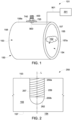
FIG. 1 is a partial cross-sectional view of a temperature sensing system in accordance with an embodiment; -
FIG. 2 is a cross-section view of a portion of a vessel, in accordance with an embodiment; -
FIG. 3 is a cross-sectional view of a of a portion of a vessel, in accordance with another embodiment; -
FIG. 4 is a cross-sectional view of a temperature sensing system in accordance with an embodiment; -
FIG. 5 is a cross-sectional view of a temperature sensing system in accordance with an embodiment; -
FIG. 6 is a view of a retention plate of a temperature sensing system in accordance with an embodiment; and -
FIG. 7 is a cross-sectional view of a retention plate of a temperature sensing system in accordance with an exemplary embodiment; - Reference will be made below in detail to exemplary embodiments of the invention, examples of which are illustrated in the accompanying drawings. Wherever possible, the same reference characters used throughout the drawings refer to the same or like parts, without duplicative description.
- As used herein, the terms "substantially," "generally," and "about" indicate conditions within reasonably achievable manufacturing and assembly tolerances, relative to ideal desired conditions suitable for achieving the functional purpose of a component or assembly. As used herein, "coupled," and "connected," mean that the referenced elements are directly or indirectly connected and intervening components may be present.
- Additionally, while the embodiments disclosed herein are primarily described with respect to boilers, heat recovery steam generators, and associated steam piping systems, it is to be understood that embodiments of the present invention may be applicable to other apparatus and/or methods that benefit from the teachings herein.
- Referring now to
FIG. 1 , atemperature sensing system 101 in accordance with an embodiment is illustrated. Avessel 150 defines andinterior space 154 and is arranged to contain a high-temperature gas 152 or fluid or therein. Theinterior space 154 is defined by awall 155. It will be appreciated that thevessel 150 is shown inFig. 1 in partial cut away for clarity. - In an embodiment,
wall 155 is formed from a high creep-strength steel alloy. Unless otherwise stated, as used herein, the term "steel alloy" refers to any steel alloy approved for use by International Standards for Boilers and Pressure Vessels, such as ASME Boiler & Pressure Vessel Code (BPVC). For example, in an embodiment, thevessel wall 155 is formed from P91 steel alloy. In various embodiments,wall 155 may be formed from any steel alloy that allows embodiments of the temperature sensing system to operate as described herein. - The
vessel wall 155 comprises aninner side 157 arranged proximal to theinterior space 154 and the heatedgas 152. Thevessel wall 155 also comprises anouter side 158, distal from theinterior space 154 and heatedgas 152. Accordingly, theinner side 157 may be defined by aninner surface 157a, associated with theinterior space 154 of thevessel 150. Likewise, thewall 155outer side 158 may be defined by anouter surface 158a, associated with anexterior portion 153 of thevessel 150. - It will be appreciated that although
wall 155 is depicted inFIG. 1 as generally arcuate, to thereby define acylindrical vessel 150, thewall 155 andvessel 150 of various embodiments are not so limited, and may comprise any number of shapes or geometries. For example, in other embodiments, thewall 155 may have a curved cross-section and define avessel 150 that is generally spherical. In other embodiments,wall 155 may have a generally flat cross section and define avessel 150 having a substantially cubic shape. In various embodiments,vessel 150 andwall 155 may comprise any shape that allows embodiments of the temperature sensing system to operate as described herein. Moreover,vessel 150 may include a plurality ofwalls 155 that cooperatively define theinterior space 154 therein. It is also contemplated that thewall 155 may have any thickness that allows embodiments of the temperature sensing system to operate as described herein. However, it will be appreciated that thevessel wall 155 should at least be of sufficient thickness to withstand the pressures exerted by thegas 152 therein, within the temperature ranges of operation of the system. Moreover, it will also be appreciated that thewall 155 should additionally be of sufficient thickness to enable at least two threads of a threadedstud 400 or bolt 500 to threadedly engage with at least two corresponding threads defined within a threadedrecess 250 as described in more detail hereinbelow. - The
outer side 158 ofwall 155 includes a threadedrecess 250 defined therein. Therecess 250 may be arranged as a blind hole withinwall 155. In other embodiments, therecess 250 may be arranged as a through-hole throughwall 155. In an embodiment, the threadedrecess 250 defines a cylindrical chamber having a longitudinal axis "L" therethrough. The longitudinal axis "L" may be orthogonal or transverse to a longitudinal axis W defined bywall 155. For example, in an embodiment wherein thevessel 150 comprises a cylindrical pipe having a circular cross-section, the threadedrecess 250 is defined inouter surface 153 in theouter side 158 of thewall 155 and oriented radially with respect to the circular cross section of thecylindrical vessel 150. The threadedrecess 250 is sized and configured to receive a threadedstud 400 orbolt 500 therein. Afirst end 250a ofrecess 250 is open and operative to receive thestud 400 or bolt 500 therethrough. - In an embodiment where
recess 250 is arranged as a blind hole withinwall 155, asecond end 250b ofrecess 250, opposite thefirst end 250a, is closed. In such an embodiment the closedsecond end 250b ofrecess 250 is operative to receive the firstdistal end 411 of thestud 400 thereat, as well as to prevent thestud 400 from extending throughvessel wall 155inner side 157 and into theinterior space 154. The closedsecond end 250b ofrecess 250 withinwall 155 may be defined by asurface 262. - Alternatively, in an embodiment where
recess 250 is arranged as a through-hole throughwall 155, asecond end 250b ofrecess 250, opposite thefirst end 250a, defines anopening 266 at thevessel wall 155inner side 157 operative to receive the firstdistal end 411 of thestud 400 therethrough, and allow thestud 400 to extending throughvessel wall 155inner side 157 and into theinterior space 154. - The threaded
recess 250 inwall 155 is further defined by aninterior surface 257 withinwall 155. Theinterior surface 257 may have a substantially cylindrical shape. In an embodiment,interior surface 257 includesthreads 259 formed thereon. Thethreads 259 are configured to threadedly engage withcorresponding threads 431 formed on the first threaded portion 411a of threadedstud 400. In other embodiments, thethreads 259 are configured to threadedly engage withcorresponding threads 531 formed on the first threadedportion 511 ofbolt 500. - In various embodiments, the threaded
recess 250 defines afirst rim portion 251 disposed thereabout on theouter surface 158a ofouter wall 158. In an embodiment, therim portion 251 comprises a rounded edge to reduce the stress risers at thefirst rim portion 251. For example, in an embodiment, thefirst rim portion 251 has a 1/8 in. radius. In certain embodiments, whererecess 250 is arranged as a through-hole throughwall 155, the threadedrecess 250 may define asecond rim portion 252 disposed thereabout opening 266 on theinner surface 157a on theinner side 157 ofwall 155. In an embodiment, thesecond rim portion 251 comprises a rounded edge to reduce the stress risers at therim portion 252. For example, in an embodiment, thesecond rim portion 252 has a 1/8 in. radius. - In an embodiment, the threaded
stud 400 is threadedly engaged with thethreads 259 formed within the threadedrecess 250. In embodiments, the threadedstud 400 may comprise a threaded rod, while in other embodiments, the threadedstud 400 may comprise abolt 500 with integrally formedhead 525. Generally, the threadedstud 400 is an elongate cylinder having afirst end 411 and asecond end 422 opposite thefirst end 411. The threadedstud 400 comprises a first threaded portion 411a at a first end ofstud 411 havingthreads 431 disposed thereon, configured to cooperatively engage thethreads 259 within threadedrecess 250. Threadedstud 400 may additionally comprise a second threadedportion 422b at asecond end 422 of thestud 400 havingthreads 432 disposed thereon. In an embodiment, the thread profile of thethreads 431 on the first threaded portion 411a have the same thread profile as thethreads 432 on the second threadedportion 422b. In other embodiments, the thread profile of thethreads 431 on the first threaded portion 411a is different from the thread profile of thethreads 432 on the second threadedportion 422b. - It will be appreciated that due to the mechanical stresses on the vessel walls created at the expected high temperatures (e.g. about 1200° F) and pressures at a normal operating condition of certain boiler vessels, it is important to minimize any additional stresses to the vessel when forming the various embodiments. Accordingly, in certain embodiments the
threads 259 in threadedrecess 250 and thecorresponding threads 431 on at least the first threaded portion 411a of threadedstud 400 are formed to reduce stress risers associated with sharp edges of conventional threads as used in conventional boiler structures. For example, in embodiments thethreads recess 250 and first threaded portion 411a ofstud 400 may comprise knuckle, or round threads. For example, thethreads recess 250 and first threaded portion 411a ofstud 400 may be arranged according to industry standard round thread profiles such as DIN 405, DIN 15403, and DIN 2040, - For example, knuckle threads with a flat 30 degree flank thread angle may be used for inch pitches and diameters ranging from 8mm to 200mm. For a thread pitch p, the crest and root rounding radius may be slightly less than p/4, and approximately the middle third of each thread flank may be flat. Alternatively, for a thread angle at the flank of 60 degrees, the crest and root rounding radius may be configured to be approximately p/6 for threads of pitch p. In other embodiments for a 0.125 inch thread pitch (8 threads per inch), the round thread root radius may be 0.017 inch, and the crest radius is 0.020 inch.
- Due to the rounded edges of the thread profile, the round or knuckle thread advantageously reduces stress risers in the
stud 400 andvessel wall 155, while at the same time withstanding the very large forces exhibited at the expected high temperatures and pressures of boiler vessels. In other embodiments, other thread profiles, such as sinusoidal thread profiles, or half-circle thread profiles, may be employed. - Additionally, the
first end 411 of threadedstud 400 defines a firstdistal end 461. In embodiments whererecess 250 is arranged as a blind hole inwall 155, the firstdistal end 461 ofstud 400 and thesurface 262 of closedsecond end 250b ofrecess 250 are arranged to have corresponding geometries to maximize the mating surface areas between the firstdistal end 461 ofstud 400 and thesurface 262. In an embodiment, the firstdistal end 461 is formed to have a hemispherical geometry. For example, the hemispherical geometry may define a rounded cross-section at the tip of firstdistal end 461. In an embodiment, the radius of the rounded cross-section tip at firstdistal end 461 is substantially equal to 66% of the diameter of thefirst end 411 of threadedstud 400. In certain embodiments, where the firstdistal end 461 ofstud 400 has a curved geometry, and whererecess 250 is arranged as a blind hole inwall 155, then thesurface 262 of closedsecond end 250b ofrecess 250 may likewise comprise a curved or rounded geometry corresponding to the cross-section of the tip of firstdistal end 461 ofstud 400 to nestingly receive the tip of firstdistal end 461 thereat. In other embodiments, other geometries at the firstdistal end 461 may be employed. By configuring the tip of the firstdistal end 461 ofstud 400 to be nested or fit against the closedsecond end surface 262 ofrecess 250 enables an improved thermal transfer between thevessel wall 155 andstud 400 while at the same time reducing stress risers caused by sharp or squared edges. - The rounded cross-section of the tip at first
distal end 461 and the corresponding rounded cross-section of thesurface 262 of closedsecond end 250b ofrecess 250 reduces stress risers in thestud 400 andvessel wall 155, while at the same time withstanding the very large forces exhibited at the expected high temperatures and pressures of boiler vessels, and providing improved thermal transfer between thevessel wall 155 andstud 400. - Additionally, the
first end 511 ofbolt 500 defines a firstdistal end 561. In embodiments whererecess 250 is arranged as a blind hole inwall 155, the firstdistal end 561 ofbolt 500 and thesurface 262 of closedsecond end 250b ofrecess 250 are arranged to have corresponding geometries to maximize the mating surface areas between the firstdistal end 561 ofbolt 500 and thesurface 262. In an embodiment, the firstdistal end 561 is formed to have a hemispherical geometry. For example, the hemispherical geometry may define a rounded cross-section at the tip of firstdistal end 561. In an embodiment, the radius of the rounded cross-section tip at firstdistal end 561 is substantially equal to 66% of the diameter of thefirst end 511 ofbolt 500. In certain embodiments, where the firstdistal end 561 ofbolt 500 has a curved geometry, and whererecess 250 is arranged as a blind hole inwall 155, then thesurface 262 of closedsecond end 250b ofrecess 250 may likewise comprise a curved or rounded geometry corresponding to the cross-section of the tip of firstdistal end 561 ofbolt 500 to nestingly receive the tip of firstdistal end 561 thereat. In other embodiments, other geometries at the firstdistal end 561 may be employed. By configuring the tip of the firstdistal end 561 ofbolt 500 to be nested or fit against the closedsecond end surface 262 ofrecess 250 an improved thermal transfer is enabled between thevessel wall 155 and bolt 500 while at the same time reducing stress risers caused by sharp or squared edges. - The rounded cross-section of the tip at first
distal end 561 and the corresponding rounded cross-section of thesurface 262 of closedsecond end 250b ofrecess 250 reduces stress risers in thebolt 500 andvessel wall 155, while at the same time withstanding the very large forces exhibited at the expected high temperatures and pressures of boiler vessels, and providing improved thermal transfer between thevessel wall 155 andbolt 500. - In various embodiments, a retention assembly 750 (
Fig. 5 ) is arranged to couple atemperature sensor 900 to thevessel 150 by applying a mechanical retention force "F" totemperature sensor 900 disposed therebetween. Thetemperature sensor 900 may comprise awire 901 to convey a signal indicative of the temperature detected bysensor 900 to instrumentation orcircuitry 301 in a known manner. By applying a strong retention force F to couple thetemperature sensor 900 to thevessel 150, accurate and reliable indication of the temperature of the vessel may be obtained without need of welding thetemperature sensor 900 tovessel 150. - For example, in an embodiment, the
retention assembly 750 may comprise a threadednut 725 threadedly engaged on the second threadedportion 422b ofstud 400, and aretention plate 740, disposed between the threadednut 725 and thevessel 150. Thenut 725 is arranged to cooperate with the threadedstud 400 and theretention plate 740 to apply the retention force F on thetemperature sensor 900 in the direction ofvessel 150 as thenut 725 is advanced or tightened on thestud 400. For example, in an embodiment, theretention plate 740 includes anaperture 714 defined therethrough. Theaperture 714 is sized and disposed to receive thestud 400 or bolt 500 therethrough. Theretention plate 740 is coupled to and responsive to movement of thenut 725. As thenut 725 is advanced or tightened onstud 400, theretention plate 740 driven towardvessel 150 by thenut 725. Theretention plate 740 comprises afirst side 741 facing and in mechanical communication with thenut 725. Theretention plate 740 also comprises asecond side 742 opposite thefirst side 741 and facingvessel 150. - In an embodiment, the
temperature sensor 900 is disposed between thevessel 150 and thesecond side 742 ofretention plate 740. As thenut 725 is tightened onstud 400, thenut 725 applies a net retention force F in the direction ofvessel 150 to theretention plate 740 which is then transmitted by theretention plate 740 to thetemperature sensor 900 in the direction ofvessel 150, thereby coupling the temperature sensor to thevessel 150 without welding. - Alternatively, in an embodiment, the
temperature sensor 900 is rigidly coupled to any surface of theretention plate 740. Thesensor 900 may be coupled using any number of known techniques for coupling a sensor to a surface, such as for example, welding, staking, or by use of an adhesive toretention plate 740. - In another embodiment, the
stud 400 andnut 725 may be integrally formed to define abolt 500 having abolt head 525. Generally, thebolt 500 is an elongate cylinder having afirst end 511 and asecond end 522 opposite thefirst end 511. Thebolt 500 comprises a first threadedportion 511a at thefirst end 511 ofbolt 500 havingthreads 531 disposed thereon, configured to cooperatively engage thethreads 259 within threadedrecess 250. - The
retention plate 740 is coupled to and responsive to movement of thebolt head 525, such that as thebolt 500 is advanced or tightened into the threadedhole 250, theretention plate 740 driven toward thevessel 150. Thebolt head 525 is arranged to cooperate with theretention plate 740 to apply a retention force on thetemperature sensor 900 in the direction ofvessel 150. Theretention plate 740 is coupled to and responsive to movement of thebolt head 525. As thebolt 500 is advanced or tightened into the threadedhole 250, theretention plate 740 driven towardvessel 150 by thebolt head 525. Theretention plate 740 comprises afirst side 741 facing and in mechanical communication with thebolt head 525. Theretention plate 740 also comprises asecond side 742 opposite thefirst side 741 and facingvessel 150. Thetemperature sensor 900 is disposed between thevessel 150 and thesecond side 742 ofretention plate 740. Asbolt 500 is advanced or tightened into the threadedhole 250, thebolt head 525 applies a net retention force F in the direction ofvessel 150 to theretention plate 740 which is then transmitted by theretention plate 740 to thetemperature sensor 900 in the direction ofvessel 150. In some embodiments, an additional plate (not shown), such as a washer, may be disposed between thebolt head 525 and thefirst side 741 ofretention plate 740. - In other embodiments, the
temperature sensor 900 may directly coupled to a surface of the retention plate, for example by welding, staking, bonding, or gluing. In such embodiments, theretention plate 740 is secured to thevessel 150 by a threaded fastener such as thebolt 500 or thestud 400 andnut 725, such that as thebolt 500 is advanced or tightened into the threadedhole 250, (or thenut 725 is advanced or tightened on stud 400), theretention plate 740 is driven toward thevessel 150. Thebolt head 525 ornut 725 is thereby arranged to apply a retention force F on theretention plate 740 in the direction ofvessel 150 to ensure a robust mechanical connection between theretention plate 740 andouter surface 153 to enable efficient thermal transfer between thevessel wall 155 and theretention plate 741. Theretention plate 740 comprises at least afirst side 741 facing and in mechanical communication with thebolt head 525 ornut 725. Theretention plate 740 also comprises at least asecond side 742 opposite thefirst side 741 and facingvessel 150. Thetemperature sensor 900 may be coupled to the first, second, 741, 742, or any other any convenient surface of theretention plate 740. In some embodiments, an additional plate (not shown), such as a washer, may be disposed between thebolt head 525 ornut 725 and thesecond side 742 ofretention plate 740. - In other embodiments, the
retention plate 740 andnut 725 orbolt head 525 may be integrally formed or fixedly coupled together. In still other embodiments, theretention assembly 750 comprising thestud 400,nut 725 andretention plate 740 may be integrally formed to operate as described herein. - The second side of
retention plate 742 may define a generally flat or planar surface. In some embodiments, (e.g., when theouter surface 153 in theouter side 158 of thewall 155 comprises a curved surface), the second side ofretention plate 742 may likewise define a corresponding curved surface between theouter surface 153 of thewall 155 and the second side ofretention plate 742, wherein the correspondingcurved surfaces temperature sensor 900 moving due to mechanical stresses on any of the components. In embodiments, the second side ofretention plate 742 defines a curved profile having a radius substantially identical to the radius of theouter surface 153 in theouter side 158 of thewall 155. - The
second side 742 ofretention plate 740 may further comprise arecess 767 defined therein. Therecess 767 is sized to receive at least a portion of thetemperature sensor 900, and/or one ormore wires 901 associated with the temperature sensor, therein. For example, therecess 767 may comprise a groove defined in a surface of thesecond side 742 ofretention plate 740. Therecess 767 accommodates therein a depth associated with at least one of thetemperature sensor 900 and the associatedwire 901. In an embodiment, the portion of thetemperature sensor 900 and associatedwiring 901 disposed between theretention plate 740 and vessel define afirst sensor portion 901 and asecond portion 902. The first portion may be received within therecess 767, while asecond portion 902 is not received within therecess 767. In another embodiment, both the first andsecond portions recess 767. Disposing at least a portion of at least one of the first andsecond portions recess 767 effectively reduces or minimizes any gap defined between thesecond side 742 ofretention plate 740 and thevessel 150, when thetemperature sensor 900 is disposed therebetween, while still maintaining a secure connection between thetemperature sensor 900 and thevessel 150. In embodiments, therecess 767 prevents movement ofsensor 900 away fromvessel 150 and increases heat transfer to the sensor by providing more surface area contact with thesensor 900. - In an embodiment, the groove 767a comprises an arcuate geometry disposed radially about the
stud 400. Embodiments comprising an arcuate groove 767a having thetemperature sensor 900 and/orwiring 901 disposed therein will reduce tensile stress applied to thesensor 900 andwiring 901 during installation and when tightening thenut 725, while retaining thetemperature sensor 900 in a fixed position with respect to theretention assembly 750. - In other embodiments, the
second side 742 ofretention plate 740 may further comprise a plurality of projections orboss portions 778 defined thereon. Theboss portions 778 may be radially distributed about thesecond side 742 ofretention plate 740. For example, eachboss portion 778 may comprise abase portion 779 coupled to thesecond side 742 ofretention plate 740, and adistal portion 780, opposite the base portion selectively couplable to thevessel 150. In an embodiment a length of eachboss portion 778, (i.e, between thebase portion 779 and the distal portion 780) defines agap 782 between thesecond side 742 ofretention plate 740 and thevessel 150. In an embodiment, the length ofgap 782 is substantially equal to a thickness of thetemperature sensor 900 and/orwiring 901. In another embodiment, the length ofgap 782 is substantially equal to a thickness of the portion oftemperature sensor 900 and/orwiring 901 that is not received within therecess 767. In an embodiment, theboss portions 778 are arranged to be spaced from thetemperature sensor 900 and the associatedwiring 901 to provide for an even distribution about theretention plate 740 of the retention force F in the direction ofvessel 150 when thetemperature sensor 900 is disposed therebetween, while still maintaining a secure connection between thetemperature sensor 900 and thevessel 150.
Claims (12)
- A temperature measurement system (101), comprising:a vessel (150) having an interior space (154) for conducting liquids or gases at elevated temperatures, the interior space (154) defined by a wall (155) having an inner side (157) proximal to the interior space (154), and an opposing outer side (158) distal from the interior space (154), the wall (155) defining a threaded recess (250);a threaded stud (400) having a first threaded portion threadedly engaged in the threaded recess (250), and a second threaded portion extending outwardly therefrom;a nut (725) threadedly engaged on the second threaded portion of the stud (400);a retention plate (740) disposed between the nut (725) and the outer side (158) of the wall (155), having a first side (741) coupled to the nut (725), and a second side (742) facing the outer side (158) of the wall (155); anda temperature sensor (900) disposed between the second side (742) of the retention plate (740) and the outer side (158) of the wall (155) and coupled to the outer side (158) of the wall (155).
- The temperature measurement system of claim 1, wherein the threads of the threaded recess, and the corresponding threads of the first threaded portion, define round thread profiles.
- The temperature measurement system of claim 2, wherein of the threads of the second threaded portion define the same thread profile as the threads of the first threaded portion.
- The temperature measurement system of claim 1, wherein the threaded recess defines a cylindrical chamber having a longitudinal axis "L" therethrough orthogonal to a longitudinal axis defined by the wall.
- The temperature measurement system of claim 1, wherein the threaded recess defines a through hole.
- The temperature measurement system of claim 1, wherein the threaded recess defines a blind hole.
- The temperature measurement system of claim 5, wherein the stud further comprises a first distal end defining a curved cross-sectional profile; and
the blind hole comprises a surface defining a closed second end, wherein the surface of closed second end defines a curved cross-sectional profile corresponding to the profile of the first distal end of the stud to receive the first distal end thereat. - The temperature measurement system of claim of claim 1, wherein the nut and the retention plate are integrally formed.
- The temperature measurement system of claim 1 wherein the wall comprises a curved surface defining a first radius; and
the second side of retention plate defines a curved surface defining a second radius, wherein the first radius and second radius are substantially identical. - The temperature measurement system of claim 1, wherein the second side of retention plate comprises a recess defined therein sized to operatively receive at least a portion of the temperature sensor therein.
- The temperature measurement system of claim 10, wherein the recess defines a generally arcuate groove.
- The temperature measurement system of claim 10, wherein the second side of retention plate further comprises a raised portion projecting therefrom and coupled to the outer side of the wall.
Applications Claiming Priority (2)
| Application Number | Priority Date | Filing Date | Title |
|---|---|---|---|
| US16/112,953 US10775244B2 (en) | 2018-08-27 | 2018-08-27 | Temperature sensor system |
| PCT/US2019/047387 WO2020046656A1 (en) | 2018-08-27 | 2019-08-21 | Temperature sensor system |
Publications (3)
| Publication Number | Publication Date |
|---|---|
| EP3844464A1 EP3844464A1 (en) | 2021-07-07 |
| EP3844464A4 EP3844464A4 (en) | 2022-05-25 |
| EP3844464B1 true EP3844464B1 (en) | 2024-07-10 |
Family
ID=69584519
Family Applications (1)
| Application Number | Title | Priority Date | Filing Date |
|---|---|---|---|
| EP19854751.5A Active EP3844464B1 (en) | 2018-08-27 | 2019-08-21 | Temperature sensor system |
Country Status (6)
| Country | Link |
|---|---|
| US (1) | US10775244B2 (en) |
| EP (1) | EP3844464B1 (en) |
| KR (1) | KR20210038572A (en) |
| CN (1) | CN112513596A (en) |
| TW (1) | TWI823995B (en) |
| WO (1) | WO2020046656A1 (en) |
Families Citing this family (7)
| Publication number | Priority date | Publication date | Assignee | Title |
|---|---|---|---|---|
| EP4545924A1 (en) * | 2021-03-05 | 2025-04-30 | Ultra Clean Holdings, Inc. | Apparatus and method for sensing the temperature of cylindrical surfaces |
| CN115112255A (en) * | 2022-06-28 | 2022-09-27 | 上海电气核电设备有限公司 | Mechanical fixing device of thermocouple capable of being installed on spherical sealing head and method thereof |
| CN115196212B (en) * | 2022-08-29 | 2023-07-07 | 徐州盛安化工科技有限公司 | A temperature measuring device for fuel oil storage and transportation |
| CN117232669B (en) * | 2023-10-24 | 2024-01-30 | 常州宏川石化仓储有限公司 | Temperature sensor assembly, incineration system and waste gas treatment method |
| CN118362215B (en) * | 2024-06-19 | 2024-09-20 | 诸城市天泰热电有限公司 | Chemical water treatment pipeline temperature detection alarm device of waste heat power plant |
| CN119525903B (en) * | 2024-12-02 | 2025-11-21 | 中国华电香港有限公司印尼Pe公司 | Angle-adjustable welding processing device for boiler |
| CN120740782B (en) * | 2025-08-21 | 2025-12-30 | 成都凯天电子股份有限公司 | Temperature sensor for controlling opening degree of valve of air-inducing temperature-controlling system |
Family Cites Families (26)
| Publication number | Priority date | Publication date | Assignee | Title |
|---|---|---|---|---|
| US2712295A (en) * | 1955-07-05 | haynes | ||
| US2048680A (en) * | 1934-12-24 | 1936-07-28 | Standard Oil Co | Thermocouple shield |
| US2302640A (en) * | 1940-12-23 | 1942-11-17 | Fedders Mfg Co Inc | Refrigeration thermometer |
| US2491023A (en) * | 1945-09-12 | 1949-12-13 | Du Pont | Photographic film elements |
| US2971998A (en) | 1958-08-05 | 1961-02-14 | Gen Motors Corp | Thermocouple lead attachment |
| DE7126784U (en) * | 1971-07-13 | 1972-03-16 | Bosch R Gmbh | DEVICE FOR FASTENING A HEAT SENSOR TUBE |
| US4338479A (en) | 1980-05-08 | 1982-07-06 | Pneumo Corporation | Surface thermocouple assembly and method of making same |
| DE3238769A1 (en) * | 1982-10-20 | 1984-04-26 | Kurt Wolf & Co Kg, 7547 Wildbad | FITTING ON A COOKING VESSEL, IN PARTICULAR STEAM PRESSURE COOKER |
| US4477687A (en) | 1983-06-06 | 1984-10-16 | Finney Philip F | Thermocouple and method of making the thermocouple and of mounting the thermocouple on a heat exchanger tube |
| US4515484A (en) | 1983-12-15 | 1985-05-07 | At&T Technologies, Inc. | Temperature testing apparatus for an electronic circuit substrate |
| US5070706A (en) * | 1990-07-10 | 1991-12-10 | Sundstrand Corporation | Superheat sensor with single coupling to fluid line |
| JP2882105B2 (en) | 1991-06-28 | 1999-04-12 | 日本精工株式会社 | Method and apparatus for measuring the preload of a rolling bearing |
| JP2544943Y2 (en) * | 1991-07-24 | 1997-08-20 | 曙ブレーキ工業株式会社 | Braking fluid temperature detector in brake |
| DE4431291B4 (en) | 1994-09-02 | 2004-03-25 | Alstom | High temperature probe |
| FR2737007B1 (en) | 1995-07-18 | 1997-09-19 | Elf Antar France | DEVICE FOR MEASURING THE TEMPERATURE OF A HOT WALL |
| DE19608675C2 (en) * | 1996-03-06 | 1999-07-29 | Delphi Automotive Systems Gmbh | Temperature measuring device with a media-carrying pipeline |
| US5951165A (en) * | 1998-08-07 | 1999-09-14 | Exxon Research And Engineering Co. | Temperature sensor |
| JP3782958B2 (en) | 2001-10-29 | 2006-06-07 | 助川電気工業株式会社 | Heat flux meter |
| US6827486B2 (en) * | 2002-11-22 | 2004-12-07 | Welker Engineering Company | Temperature probe and insertion device |
| US20060227850A1 (en) * | 2005-04-06 | 2006-10-12 | Johnson Clifton R | Slip on bath water thermometer |
| US7785003B2 (en) * | 2005-09-08 | 2010-08-31 | John R Blichmann | Beer brewing thermometer |
| CN100582695C (en) * | 2005-11-04 | 2010-01-20 | 鸿富锦精密工业(深圳)有限公司 | Thermocouple fixture and temperature measuring device |
| JP2008215846A (en) * | 2007-02-28 | 2008-09-18 | Denso Corp | Temperature sensor mounting structure |
| US8337081B1 (en) * | 2012-01-09 | 2012-12-25 | Honeywell International Inc. | Sensor assembly for mounting a temperature sensor to a tank |
| TWI519403B (en) * | 2013-06-24 | 2016-02-01 | 緯創資通股份有限公司 | Hot runner structure with temperature detector |
| TWI476384B (en) * | 2014-05-08 | 2015-03-11 | China Steel Corp | Surface temperature measurement device |
-
2018
- 2018-08-27 US US16/112,953 patent/US10775244B2/en active Active
-
2019
- 2019-08-21 WO PCT/US2019/047387 patent/WO2020046656A1/en not_active Ceased
- 2019-08-21 CN CN201980049534.4A patent/CN112513596A/en active Pending
- 2019-08-21 EP EP19854751.5A patent/EP3844464B1/en active Active
- 2019-08-21 KR KR1020217003872A patent/KR20210038572A/en not_active Ceased
- 2019-08-26 TW TW108130428A patent/TWI823995B/en active
Also Published As
| Publication number | Publication date |
|---|---|
| WO2020046656A1 (en) | 2020-03-05 |
| US10775244B2 (en) | 2020-09-15 |
| TWI823995B (en) | 2023-12-01 |
| CN112513596A (en) | 2021-03-16 |
| KR20210038572A (en) | 2021-04-07 |
| EP3844464A4 (en) | 2022-05-25 |
| TW202009452A (en) | 2020-03-01 |
| US20200064203A1 (en) | 2020-02-27 |
| EP3844464A1 (en) | 2021-07-07 |
Similar Documents
| Publication | Publication Date | Title |
|---|---|---|
| US10775244B2 (en) | Temperature sensor system | |
| EP2369216B1 (en) | Apparatus for attaching a device to a circular structure | |
| US11607929B2 (en) | Thermal cycle resistant fastening system for refrigerant fitting | |
| US20020039378A1 (en) | Temperature sensor mounting structure | |
| US12196650B2 (en) | Process inserts, assemblies, and related methods for high velocity applications | |
| CN1135371C (en) | Temperature probe | |
| CA1205572A (en) | Thermocouple and method of making the thermocouple and of mounting the thermocouple on a heat exchanger tube | |
| CN115717944A (en) | Direct temperature measuring type COT surface thermocouple | |
| EP3156776B1 (en) | Pressure sensor | |
| US7870655B2 (en) | Process of endforming a tubular assembly | |
| JP2003287464A (en) | Thermocouple well | |
| US20240035624A1 (en) | Double sealed pressure containment assembly | |
| CN108981945A (en) | Sensor | |
| KR101608394B1 (en) | The butterfly valve that have a pressure gauge and thermometer | |
| JP5123737B2 (en) | Method for forming pressure receiving portion of pressure sensing device | |
| US20220220991A1 (en) | Screw connection system, method for screwing together reinforced long molded parts, and use of a screw connection system | |
| US20240011843A1 (en) | Backshell assembly | |
| US11066889B2 (en) | Subsea assembly | |
| JP7488525B2 (en) | Sensor fixture and fluid control device | |
| US7837041B2 (en) | Method of determining the robustness of endformed tubular assembly and predicting the performance of such assembly in high pressure applications | |
| CN120333640A (en) | Temperature measurement structure for high-speed and heavy-load rolling bearings | |
| EP4097415A1 (en) | Plug for sealing tubes of shell and tube heat exchangers | |
| CN121498766A (en) | Sensor housing and flange module for sensor housing | |
| EP3453999A1 (en) | Clamp assembly and heat exchanger with clamp assembly | |
| CN114787476A (en) | Connecting device with integrated sensor |
Legal Events
| Date | Code | Title | Description |
|---|---|---|---|
| STAA | Information on the status of an ep patent application or granted ep patent |
Free format text: STATUS: THE INTERNATIONAL PUBLICATION HAS BEEN MADE |
|
| STAA | Information on the status of an ep patent application or granted ep patent |
Free format text: STATUS: REQUEST FOR EXAMINATION WAS MADE |
|
| PUAI | Public reference made under article 153(3) epc to a published international application that has entered the european phase |
Free format text: ORIGINAL CODE: 0009012 |
|
| 17P | Request for examination filed |
Effective date: 20210218 |
|
| AK | Designated contracting states |
Kind code of ref document: A1 Designated state(s): AL AT BE BG CH CY CZ DE DK EE ES FI FR GB GR HR HU IE IS IT LI LT LU LV MC MK MT NL NO PL PT RO RS SE SI SK SM TR |
|
| DAV | Request for validation of the european patent (deleted) | ||
| DAX | Request for extension of the european patent (deleted) | ||
| A4 | Supplementary search report drawn up and despatched |
Effective date: 20220425 |
|
| RIC1 | Information provided on ipc code assigned before grant |
Ipc: G01K 7/02 20210101ALI20220420BHEP Ipc: G01K 1/143 20210101ALI20220420BHEP Ipc: G01K 5/32 20060101ALI20220420BHEP Ipc: B65D 90/48 20060101ALI20220420BHEP Ipc: G01K 1/14 20210101AFI20220420BHEP |
|
| RAP1 | Party data changed (applicant data changed or rights of an application transferred) |
Owner name: GENERAL ELECTRIC TECHNOLOGY GMBH |
|
| GRAP | Despatch of communication of intention to grant a patent |
Free format text: ORIGINAL CODE: EPIDOSNIGR1 |
|
| STAA | Information on the status of an ep patent application or granted ep patent |
Free format text: STATUS: GRANT OF PATENT IS INTENDED |
|
| INTG | Intention to grant announced |
Effective date: 20240321 |
|
| GRAS | Grant fee paid |
Free format text: ORIGINAL CODE: EPIDOSNIGR3 |
|
| GRAA | (expected) grant |
Free format text: ORIGINAL CODE: 0009210 |
|
| STAA | Information on the status of an ep patent application or granted ep patent |
Free format text: STATUS: THE PATENT HAS BEEN GRANTED |
|
| AK | Designated contracting states |
Kind code of ref document: B1 Designated state(s): AL AT BE BG CH CY CZ DE DK EE ES FI FR GB GR HR HU IE IS IT LI LT LU LV MC MK MT NL NO PL PT RO RS SE SI SK SM TR |
|
| REG | Reference to a national code |
Ref country code: CH Ref legal event code: EP |
|
| REG | Reference to a national code |
Ref country code: DE Ref legal event code: R096 Ref document number: 602019055109 Country of ref document: DE |
|
| REG | Reference to a national code |
Ref country code: LT Ref legal event code: MG9D |
|
| REG | Reference to a national code |
Ref country code: NL Ref legal event code: MP Effective date: 20240710 |
|
| PG25 | Lapsed in a contracting state [announced via postgrant information from national office to epo] |
Ref country code: PT Free format text: LAPSE BECAUSE OF FAILURE TO SUBMIT A TRANSLATION OF THE DESCRIPTION OR TO PAY THE FEE WITHIN THE PRESCRIBED TIME-LIMIT Effective date: 20241111 |
|
| REG | Reference to a national code |
Ref country code: AT Ref legal event code: MK05 Ref document number: 1702414 Country of ref document: AT Kind code of ref document: T Effective date: 20240710 |
|
| PG25 | Lapsed in a contracting state [announced via postgrant information from national office to epo] |
Ref country code: NL Free format text: LAPSE BECAUSE OF FAILURE TO SUBMIT A TRANSLATION OF THE DESCRIPTION OR TO PAY THE FEE WITHIN THE PRESCRIBED TIME-LIMIT Effective date: 20240710 |
|
| PG25 | Lapsed in a contracting state [announced via postgrant information from national office to epo] |
Ref country code: PT Free format text: LAPSE BECAUSE OF FAILURE TO SUBMIT A TRANSLATION OF THE DESCRIPTION OR TO PAY THE FEE WITHIN THE PRESCRIBED TIME-LIMIT Effective date: 20241111 Ref country code: NL Free format text: LAPSE BECAUSE OF FAILURE TO SUBMIT A TRANSLATION OF THE DESCRIPTION OR TO PAY THE FEE WITHIN THE PRESCRIBED TIME-LIMIT Effective date: 20240710 |
|
| PG25 | Lapsed in a contracting state [announced via postgrant information from national office to epo] |
Ref country code: NO Free format text: LAPSE BECAUSE OF FAILURE TO SUBMIT A TRANSLATION OF THE DESCRIPTION OR TO PAY THE FEE WITHIN THE PRESCRIBED TIME-LIMIT Effective date: 20241010 |
|
| PG25 | Lapsed in a contracting state [announced via postgrant information from national office to epo] |
Ref country code: GR Free format text: LAPSE BECAUSE OF FAILURE TO SUBMIT A TRANSLATION OF THE DESCRIPTION OR TO PAY THE FEE WITHIN THE PRESCRIBED TIME-LIMIT Effective date: 20241011 Ref country code: PL Free format text: LAPSE BECAUSE OF FAILURE TO SUBMIT A TRANSLATION OF THE DESCRIPTION OR TO PAY THE FEE WITHIN THE PRESCRIBED TIME-LIMIT Effective date: 20240710 Ref country code: FI Free format text: LAPSE BECAUSE OF FAILURE TO SUBMIT A TRANSLATION OF THE DESCRIPTION OR TO PAY THE FEE WITHIN THE PRESCRIBED TIME-LIMIT Effective date: 20240710 |
|
| PG25 | Lapsed in a contracting state [announced via postgrant information from national office to epo] |
Ref country code: BG Free format text: LAPSE BECAUSE OF FAILURE TO SUBMIT A TRANSLATION OF THE DESCRIPTION OR TO PAY THE FEE WITHIN THE PRESCRIBED TIME-LIMIT Effective date: 20240710 |
|
| PG25 | Lapsed in a contracting state [announced via postgrant information from national office to epo] |
Ref country code: LV Free format text: LAPSE BECAUSE OF FAILURE TO SUBMIT A TRANSLATION OF THE DESCRIPTION OR TO PAY THE FEE WITHIN THE PRESCRIBED TIME-LIMIT Effective date: 20240710 |
|
| PG25 | Lapsed in a contracting state [announced via postgrant information from national office to epo] |
Ref country code: AT Free format text: LAPSE BECAUSE OF FAILURE TO SUBMIT A TRANSLATION OF THE DESCRIPTION OR TO PAY THE FEE WITHIN THE PRESCRIBED TIME-LIMIT Effective date: 20240710 Ref country code: IS Free format text: LAPSE BECAUSE OF FAILURE TO SUBMIT A TRANSLATION OF THE DESCRIPTION OR TO PAY THE FEE WITHIN THE PRESCRIBED TIME-LIMIT Effective date: 20241110 |
|
| PG25 | Lapsed in a contracting state [announced via postgrant information from national office to epo] |
Ref country code: HR Free format text: LAPSE BECAUSE OF FAILURE TO SUBMIT A TRANSLATION OF THE DESCRIPTION OR TO PAY THE FEE WITHIN THE PRESCRIBED TIME-LIMIT Effective date: 20240710 |
|
| PG25 | Lapsed in a contracting state [announced via postgrant information from national office to epo] |
Ref country code: ES Free format text: LAPSE BECAUSE OF FAILURE TO SUBMIT A TRANSLATION OF THE DESCRIPTION OR TO PAY THE FEE WITHIN THE PRESCRIBED TIME-LIMIT Effective date: 20240710 Ref country code: RS Free format text: LAPSE BECAUSE OF FAILURE TO SUBMIT A TRANSLATION OF THE DESCRIPTION OR TO PAY THE FEE WITHIN THE PRESCRIBED TIME-LIMIT Effective date: 20241010 |
|
| PG25 | Lapsed in a contracting state [announced via postgrant information from national office to epo] |
Ref country code: RS Free format text: LAPSE BECAUSE OF FAILURE TO SUBMIT A TRANSLATION OF THE DESCRIPTION OR TO PAY THE FEE WITHIN THE PRESCRIBED TIME-LIMIT Effective date: 20241010 Ref country code: PL Free format text: LAPSE BECAUSE OF FAILURE TO SUBMIT A TRANSLATION OF THE DESCRIPTION OR TO PAY THE FEE WITHIN THE PRESCRIBED TIME-LIMIT Effective date: 20240710 Ref country code: NO Free format text: LAPSE BECAUSE OF FAILURE TO SUBMIT A TRANSLATION OF THE DESCRIPTION OR TO PAY THE FEE WITHIN THE PRESCRIBED TIME-LIMIT Effective date: 20241010 Ref country code: LV Free format text: LAPSE BECAUSE OF FAILURE TO SUBMIT A TRANSLATION OF THE DESCRIPTION OR TO PAY THE FEE WITHIN THE PRESCRIBED TIME-LIMIT Effective date: 20240710 Ref country code: IS Free format text: LAPSE BECAUSE OF FAILURE TO SUBMIT A TRANSLATION OF THE DESCRIPTION OR TO PAY THE FEE WITHIN THE PRESCRIBED TIME-LIMIT Effective date: 20241110 Ref country code: HR Free format text: LAPSE BECAUSE OF FAILURE TO SUBMIT A TRANSLATION OF THE DESCRIPTION OR TO PAY THE FEE WITHIN THE PRESCRIBED TIME-LIMIT Effective date: 20240710 Ref country code: GR Free format text: LAPSE BECAUSE OF FAILURE TO SUBMIT A TRANSLATION OF THE DESCRIPTION OR TO PAY THE FEE WITHIN THE PRESCRIBED TIME-LIMIT Effective date: 20241011 Ref country code: FI Free format text: LAPSE BECAUSE OF FAILURE TO SUBMIT A TRANSLATION OF THE DESCRIPTION OR TO PAY THE FEE WITHIN THE PRESCRIBED TIME-LIMIT Effective date: 20240710 Ref country code: ES Free format text: LAPSE BECAUSE OF FAILURE TO SUBMIT A TRANSLATION OF THE DESCRIPTION OR TO PAY THE FEE WITHIN THE PRESCRIBED TIME-LIMIT Effective date: 20240710 Ref country code: BG Free format text: LAPSE BECAUSE OF FAILURE TO SUBMIT A TRANSLATION OF THE DESCRIPTION OR TO PAY THE FEE WITHIN THE PRESCRIBED TIME-LIMIT Effective date: 20240710 Ref country code: AT Free format text: LAPSE BECAUSE OF FAILURE TO SUBMIT A TRANSLATION OF THE DESCRIPTION OR TO PAY THE FEE WITHIN THE PRESCRIBED TIME-LIMIT Effective date: 20240710 |
|
| REG | Reference to a national code |
Ref country code: DE Ref legal event code: R097 Ref document number: 602019055109 Country of ref document: DE |
|
| PG25 | Lapsed in a contracting state [announced via postgrant information from national office to epo] |
Ref country code: DK Free format text: LAPSE BECAUSE OF FAILURE TO SUBMIT A TRANSLATION OF THE DESCRIPTION OR TO PAY THE FEE WITHIN THE PRESCRIBED TIME-LIMIT Effective date: 20240710 Ref country code: SM Free format text: LAPSE BECAUSE OF FAILURE TO SUBMIT A TRANSLATION OF THE DESCRIPTION OR TO PAY THE FEE WITHIN THE PRESCRIBED TIME-LIMIT Effective date: 20240710 Ref country code: RO Free format text: LAPSE BECAUSE OF FAILURE TO SUBMIT A TRANSLATION OF THE DESCRIPTION OR TO PAY THE FEE WITHIN THE PRESCRIBED TIME-LIMIT Effective date: 20240710 |
|
| PG25 | Lapsed in a contracting state [announced via postgrant information from national office to epo] |
Ref country code: LU Free format text: LAPSE BECAUSE OF NON-PAYMENT OF DUE FEES Effective date: 20240821 |
|
| PG25 | Lapsed in a contracting state [announced via postgrant information from national office to epo] |
Ref country code: MC Free format text: LAPSE BECAUSE OF FAILURE TO SUBMIT A TRANSLATION OF THE DESCRIPTION OR TO PAY THE FEE WITHIN THE PRESCRIBED TIME-LIMIT Effective date: 20240710 Ref country code: EE Free format text: LAPSE BECAUSE OF FAILURE TO SUBMIT A TRANSLATION OF THE DESCRIPTION OR TO PAY THE FEE WITHIN THE PRESCRIBED TIME-LIMIT Effective date: 20240710 |
|
| PG25 | Lapsed in a contracting state [announced via postgrant information from national office to epo] |
Ref country code: CZ Free format text: LAPSE BECAUSE OF FAILURE TO SUBMIT A TRANSLATION OF THE DESCRIPTION OR TO PAY THE FEE WITHIN THE PRESCRIBED TIME-LIMIT Effective date: 20240710 |
|
| PG25 | Lapsed in a contracting state [announced via postgrant information from national office to epo] |
Ref country code: SK Free format text: LAPSE BECAUSE OF FAILURE TO SUBMIT A TRANSLATION OF THE DESCRIPTION OR TO PAY THE FEE WITHIN THE PRESCRIBED TIME-LIMIT Effective date: 20240710 |
|
| PLBE | No opposition filed within time limit |
Free format text: ORIGINAL CODE: 0009261 |
|
| STAA | Information on the status of an ep patent application or granted ep patent |
Free format text: STATUS: NO OPPOSITION FILED WITHIN TIME LIMIT |
|
| 26N | No opposition filed |
Effective date: 20250411 |
|
| GBPC | Gb: european patent ceased through non-payment of renewal fee |
Effective date: 20241010 |
|
| REG | Reference to a national code |
Ref country code: BE Ref legal event code: MM Effective date: 20240831 |
|
| PG25 | Lapsed in a contracting state [announced via postgrant information from national office to epo] |
Ref country code: GB Free format text: LAPSE BECAUSE OF NON-PAYMENT OF DUE FEES Effective date: 20241010 |
|
| PG25 | Lapsed in a contracting state [announced via postgrant information from national office to epo] |
Ref country code: IT Free format text: LAPSE BECAUSE OF NON-PAYMENT OF DUE FEES Effective date: 20240821 Ref country code: BE Free format text: LAPSE BECAUSE OF NON-PAYMENT OF DUE FEES Effective date: 20240831 |
|
| PG25 | Lapsed in a contracting state [announced via postgrant information from national office to epo] |
Ref country code: IE Free format text: LAPSE BECAUSE OF NON-PAYMENT OF DUE FEES Effective date: 20240821 |
|
| PG25 | Lapsed in a contracting state [announced via postgrant information from national office to epo] |
Ref country code: SE Free format text: LAPSE BECAUSE OF FAILURE TO SUBMIT A TRANSLATION OF THE DESCRIPTION OR TO PAY THE FEE WITHIN THE PRESCRIBED TIME-LIMIT Effective date: 20240710 |
|
| PGFP | Annual fee paid to national office [announced via postgrant information from national office to epo] |
Ref country code: DE Payment date: 20250724 Year of fee payment: 7 |
|
| PGFP | Annual fee paid to national office [announced via postgrant information from national office to epo] |
Ref country code: FR Payment date: 20250725 Year of fee payment: 7 |
|
| PGFP | Annual fee paid to national office [announced via postgrant information from national office to epo] |
Ref country code: CH Payment date: 20250901 Year of fee payment: 7 |
|
| PG25 | Lapsed in a contracting state [announced via postgrant information from national office to epo] |
Ref country code: CY Free format text: LAPSE BECAUSE OF FAILURE TO SUBMIT A TRANSLATION OF THE DESCRIPTION OR TO PAY THE FEE WITHIN THE PRESCRIBED TIME-LIMIT; INVALID AB INITIO Effective date: 20190821 |
|
| PG25 | Lapsed in a contracting state [announced via postgrant information from national office to epo] |
Ref country code: HU Free format text: LAPSE BECAUSE OF FAILURE TO SUBMIT A TRANSLATION OF THE DESCRIPTION OR TO PAY THE FEE WITHIN THE PRESCRIBED TIME-LIMIT; INVALID AB INITIO Effective date: 20190821 |