EP3844448B1 - A cooling system for a reflow furnace - Google Patents
A cooling system for a reflow furnace Download PDFInfo
- Publication number
- EP3844448B1 EP3844448B1 EP19765614.3A EP19765614A EP3844448B1 EP 3844448 B1 EP3844448 B1 EP 3844448B1 EP 19765614 A EP19765614 A EP 19765614A EP 3844448 B1 EP3844448 B1 EP 3844448B1
- Authority
- EP
- European Patent Office
- Prior art keywords
- gas
- cooling system
- gas discharge
- inlet
- pipeline
- Prior art date
- Legal status (The legal status is an assumption and is not a legal conclusion. Google has not performed a legal analysis and makes no representation as to the accuracy of the status listed.)
- Active
Links
Images




Classifications
-
- F—MECHANICAL ENGINEERING; LIGHTING; HEATING; WEAPONS; BLASTING
- F27—FURNACES; KILNS; OVENS; RETORTS
- F27B—FURNACES, KILNS, OVENS OR RETORTS IN GENERAL; OPEN SINTERING OR LIKE APPARATUS
- F27B9/00—Furnaces through which the charge is moved mechanically, e.g. of tunnel type; Similar furnaces in which the charge moves by gravity
- F27B9/02—Furnaces through which the charge is moved mechanically, e.g. of tunnel type; Similar furnaces in which the charge moves by gravity of multiple-track type; of multiple-chamber type; Combinations of furnaces
- F27B9/028—Multi-chamber type furnaces
-
- B—PERFORMING OPERATIONS; TRANSPORTING
- B23—MACHINE TOOLS; METAL-WORKING NOT OTHERWISE PROVIDED FOR
- B23K—SOLDERING OR UNSOLDERING; WELDING; CLADDING OR PLATING BY SOLDERING OR WELDING; CUTTING BY APPLYING HEAT LOCALLY, e.g. FLAME CUTTING; WORKING BY LASER BEAM
- B23K3/00—Tools, devices or special appurtenances for soldering, e.g. brazing, or unsoldering, not specially adapted for particular methods
- B23K3/08—Auxiliary devices therefor
- B23K3/085—Cooling, heat sink or heat shielding means
-
- B—PERFORMING OPERATIONS; TRANSPORTING
- B23—MACHINE TOOLS; METAL-WORKING NOT OTHERWISE PROVIDED FOR
- B23K—SOLDERING OR UNSOLDERING; WELDING; CLADDING OR PLATING BY SOLDERING OR WELDING; CUTTING BY APPLYING HEAT LOCALLY, e.g. FLAME CUTTING; WORKING BY LASER BEAM
- B23K3/00—Tools, devices or special appurtenances for soldering, e.g. brazing, or unsoldering, not specially adapted for particular methods
-
- B—PERFORMING OPERATIONS; TRANSPORTING
- B23—MACHINE TOOLS; METAL-WORKING NOT OTHERWISE PROVIDED FOR
- B23K—SOLDERING OR UNSOLDERING; WELDING; CLADDING OR PLATING BY SOLDERING OR WELDING; CUTTING BY APPLYING HEAT LOCALLY, e.g. FLAME CUTTING; WORKING BY LASER BEAM
- B23K1/00—Soldering, e.g. brazing, or unsoldering
- B23K1/008—Soldering within a furnace
-
- B—PERFORMING OPERATIONS; TRANSPORTING
- B23—MACHINE TOOLS; METAL-WORKING NOT OTHERWISE PROVIDED FOR
- B23K—SOLDERING OR UNSOLDERING; WELDING; CLADDING OR PLATING BY SOLDERING OR WELDING; CUTTING BY APPLYING HEAT LOCALLY, e.g. FLAME CUTTING; WORKING BY LASER BEAM
- B23K3/00—Tools, devices or special appurtenances for soldering, e.g. brazing, or unsoldering, not specially adapted for particular methods
- B23K3/08—Auxiliary devices therefor
-
- F—MECHANICAL ENGINEERING; LIGHTING; HEATING; WEAPONS; BLASTING
- F27—FURNACES; KILNS; OVENS; RETORTS
- F27B—FURNACES, KILNS, OVENS OR RETORTS IN GENERAL; OPEN SINTERING OR LIKE APPARATUS
- F27B9/00—Furnaces through which the charge is moved mechanically, e.g. of tunnel type; Similar furnaces in which the charge moves by gravity
- F27B9/30—Details, accessories or equipment specially adapted for furnaces of these types
- F27B9/3005—Details, accessories or equipment specially adapted for furnaces of these types arrangements for circulating gases
-
- F—MECHANICAL ENGINEERING; LIGHTING; HEATING; WEAPONS; BLASTING
- F27—FURNACES; KILNS; OVENS; RETORTS
- F27B—FURNACES, KILNS, OVENS OR RETORTS IN GENERAL; OPEN SINTERING OR LIKE APPARATUS
- F27B9/00—Furnaces through which the charge is moved mechanically, e.g. of tunnel type; Similar furnaces in which the charge moves by gravity
- F27B9/30—Details, accessories or equipment specially adapted for furnaces of these types
- F27B9/3077—Arrangements for treating electronic components, e.g. semiconductors
-
- F—MECHANICAL ENGINEERING; LIGHTING; HEATING; WEAPONS; BLASTING
- F27—FURNACES; KILNS; OVENS; RETORTS
- F27B—FURNACES, KILNS, OVENS OR RETORTS IN GENERAL; OPEN SINTERING OR LIKE APPARATUS
- F27B9/00—Furnaces through which the charge is moved mechanically, e.g. of tunnel type; Similar furnaces in which the charge moves by gravity
- F27B9/30—Details, accessories or equipment specially adapted for furnaces of these types
- F27B9/40—Arrangements of controlling or monitoring devices
-
- F—MECHANICAL ENGINEERING; LIGHTING; HEATING; WEAPONS; BLASTING
- F27—FURNACES; KILNS; OVENS; RETORTS
- F27D—DETAILS OR ACCESSORIES OF FURNACES, KILNS, OVENS OR RETORTS, IN SO FAR AS THEY ARE OF KINDS OCCURRING IN MORE THAN ONE KIND OF FURNACE
- F27D17/00—Arrangements for using waste heat; Arrangements for using, or disposing of, waste gases
- F27D17/10—Arrangements for using waste heat
-
- F—MECHANICAL ENGINEERING; LIGHTING; HEATING; WEAPONS; BLASTING
- F27—FURNACES; KILNS; OVENS; RETORTS
- F27B—FURNACES, KILNS, OVENS OR RETORTS IN GENERAL; OPEN SINTERING OR LIKE APPARATUS
- F27B9/00—Furnaces through which the charge is moved mechanically, e.g. of tunnel type; Similar furnaces in which the charge moves by gravity
- F27B9/12—Furnaces through which the charge is moved mechanically, e.g. of tunnel type; Similar furnaces in which the charge moves by gravity with special arrangements for preheating or cooling the charge
- F27B2009/124—Cooling
- F27B2009/126—Cooling involving the circulation of cooling gases, e.g. air
-
- F—MECHANICAL ENGINEERING; LIGHTING; HEATING; WEAPONS; BLASTING
- F27—FURNACES; KILNS; OVENS; RETORTS
- F27D—DETAILS OR ACCESSORIES OF FURNACES, KILNS, OVENS OR RETORTS, IN SO FAR AS THEY ARE OF KINDS OCCURRING IN MORE THAN ONE KIND OF FURNACE
- F27D9/00—Cooling of furnaces or of charges therein
- F27D2009/007—Cooling of charges therein
- F27D2009/0072—Cooling of charges therein the cooling medium being a gas
- F27D2009/0078—Cooling of charges therein the cooling medium being a gas in indirect contact with the charge
-
- H—ELECTRICITY
- H05—ELECTRIC TECHNIQUES NOT OTHERWISE PROVIDED FOR
- H05K—PRINTED CIRCUITS; CASINGS OR CONSTRUCTIONAL DETAILS OF ELECTRIC APPARATUS; MANUFACTURE OF ASSEMBLAGES OF ELECTRICAL COMPONENTS
- H05K2203/00—Indexing scheme relating to apparatus or processes for manufacturing printed circuits covered by H05K3/00
- H05K2203/11—Treatments characterised by their effect, e.g. heating, cooling, roughening
- H05K2203/111—Preheating, e.g. before soldering
-
- H—ELECTRICITY
- H05—ELECTRIC TECHNIQUES NOT OTHERWISE PROVIDED FOR
- H05K—PRINTED CIRCUITS; CASINGS OR CONSTRUCTIONAL DETAILS OF ELECTRIC APPARATUS; MANUFACTURE OF ASSEMBLAGES OF ELECTRICAL COMPONENTS
- H05K3/00—Apparatus or processes for manufacturing printed circuits
- H05K3/30—Assembling printed circuits with electric components, e.g. with resistors
- H05K3/32—Assembling printed circuits with electric components, e.g. with resistors electrically connecting electric components or wires to printed circuits
- H05K3/34—Assembling printed circuits with electric components, e.g. with resistors electrically connecting electric components or wires to printed circuits by soldering
- H05K3/3494—Heating processes for reflow soldering
Definitions
- the present application relates to the field of reflow furnaces, in particular to a cooling system for a reflow furnace.
- Patent documents US 6 576 030 B2 , EP 0 999 007 A1 , CN 106 017 109 A and WO 2019/204623 A1 relate to a reflow furnace configured to regulated the heat flux applied on the treated solid pieces.
- the present application provides a reflow furnace cooling system, to shorten the time taken for the reflow furnace to change from a higher heating temperature to a lower heating temperature.
- the cooling system of the present application can accelerate the cooling of the heating zone in the reflow furnace, in order to shorten the time taken for the reflow furnace to change from a higher heating temperature to a lower heating temperature.
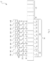
- Fig. 1A is a simplified system diagram of a cooling system 2 in an embodiment of the present application.
- the cooling system 2 comprises a reflow furnace 1.
- the reflow furnace 1 comprises a heating zone 10, a separating gas discharge zone 16 and a cooling zone 18.
- the separating gas discharge zone 16 is disposed between the heating zone 10 and the cooling zone 18, and used to separate the heating zone 10 and the cooling zone 18 when the reflow furnace 1 is operating, in order to prevent the transmission of heat of the heating zone 10 into the cooling zone 18.
- a hearth (not shown) runs through the heating zone 10, the separating gas discharge zone 16 and the cooling zone 18; the heating zone 10, the separating gas discharge zone 16 and the cooling zone 18 are all in fluid communication with the hearth.
- the heating zone 10 and the cooling zone 18 may each comprise multiple sub-regions, each of the sub-regions being in fluid communication with each other.
- the heating zone 10 comprises ten sub-regions.
- the ten sub-regions comprise a colder zone 12 and a hotter zone 14.
- the temperature of the hotter zone 14 is higher than the temperature of the colder zone 12.
- the colder zone 12 comprises two preheating zones 17.
- the hotter zone 14 comprises four even temperature zones 13 and four peak value zones 15.
- the preheating zones 17, the even temperature zones 13 and the peak value zones 15 are arranged adjacently. In the preheating zones 17 and the even temperature zones 13, a circuit board can be heated gradually, and a portion of flux in solder paste on the circuit board will be gasified.
- the circuit board continues to be heated, and the solder paste melts.
- the circuit board then passes through the separating gas discharge zone 16 and is then conveyed into the cooling zone 18.
- the cooling zone 18 comprises four sub-regions.
- the solder paste is cooled in soldering regions of the circuit board and cures, thereby connecting electronic elements to the circuit board.
- Each sub-region in the heating zone 10 is provided with a communication port.
- each sub-region of the colder zone 12 is provided with a gas discharge port 8, for discharging gas contained in the colder zone 12 out of the reflow furnace 1.
- Each sub-region in the hotter zone 14 is provided with a gas inlet 6, for causing gas to enter the reflow furnace 1.
- the cooling system 2 further comprises two gas intake pipelines 22 and two blowing apparatuses 64.
- Each of the two gas intake pipelines 22 comprises one branch gas intake inlet pipe 84 and four branch gas intake outlet pipes 82.
- One end of one branch gas intake inlet pipe 84 is connected to one end of each of four branch gas intake outlet pipes 82.
- Another end of the branch gas intake inlet pipe 84 is an inlet 28, for connecting to a corresponding one of the blowing apparatuses 64.
- Another end of each of four branch gas intake outlet pipes 82 is an outlet 24, for connecting to a corresponding one of four gas inlets 6.
- each of four outlets 24 in one gas intake pipeline 22 is connected to a corresponding gas inlet 6 in the four even temperature zones 13.
- the cooling system 2 further comprises eight gas intake valve apparatuses 42. Each of the eight gas intake valve apparatuses 42 is disposed on a corresponding one of the eight branch gas intake outlet pipes 82.
- the cooling system 2 further comprises a gas discharge pipeline 32 and an exhaust apparatus 66.
- the gas discharge pipeline 32 comprises two branch gas discharge inlet pipes 72 and one branch gas discharge outlet pipe 74; one end of each of the two branch gas discharge inlet pipes 72 is connected to one end of the branch gas discharge outlet pipe 74. Another end of each of the two branch gas discharge inlet pipes 72 is an inlet 36, for connecting to a corresponding one of the two gas discharge ports 8 of the two colder zones 12. Another end of the branch gas discharge outlet pipe 74 is an outlet 38, for connecting to the exhaust apparatus 66.
- the cooling system 2 further comprises two gas discharge valve apparatuses 44. Each of the two gas discharge valve apparatuses 44 is disposed on a corresponding one of the two branch gas discharge inlet pipes 72.
- the arrows in fig. 1A show the flow direction of air in the pipelines when the blowing apparatuses 64, the exhaust apparatus 66, the gas intake valve apparatuses 42 and the gas discharge valve apparatuses 44 are all open.
- Figs. 1B - 1C are simplified system diagrams of cooling systems 2 in two other embodiments of the present application, and are intended to show different positions of arrangement of the gas intake valve apparatuses 42 and the gas discharge valve apparatus(es) 44. Apart from the positions of arrangement of the gas intake valve apparatuses 42 and the gas discharge valve apparatus(es) 44 being different, the disposition of other components is the same as in fig. 1A in each case, so is not described again superfluously here.
- the gas intake valve apparatus 42 is disposed between the outlet 24 of the gas intake pipeline 22 and the gas inlet 6; the gas discharge valve apparatus 44 is disposed between the inlet 36 of the gas discharge pipeline 32 and the gas discharge port 8.
- the gas intake valve apparatus 42 is disposed between the inlet 28 of the gas intake pipeline 22 and the blowing apparatus 64; the gas discharge valve apparatus 44 is disposed between the outlet 38 of the gas discharge pipeline 32 and the exhaust apparatus 66.
- Fig. 2 is a simplified system diagram of a cooling system 2 in another embodiment of the present application, and is intended to show a different manner of arranging gas intake pipelines 22, blowing apparatuses 64, gas discharge pipelines 32 and exhaust apparatuses 66 in the cooling system 2.
- the cooling system 2 comprises eight gas intake pipelines 22, eight blowing apparatuses 64 and eight gas intake valve apparatuses 42.
- Each of the eight blowing apparatuses 64 is connected to a corresponding one of eight gas inlets 6 via a corresponding one of the eight gas intake pipelines 22.
- Each of the eight gas intake valve apparatuses 42 is disposed on a corresponding one of the eight gas intake pipelines 22.
- the cooling system 2 further comprises two gas discharge pipelines 32, two exhaust apparatuses 66 and two gas discharge valve apparatuses 44.
- Each of the two exhaust apparatuses 66 is connected to a corresponding one of two gas discharge ports 8 via a corresponding one of the two gas discharge pipelines 32.
- Each of the two gas discharge valve apparatuses 44 is disposed on a corresponding one of the two gas discharge pipelines 32.
- the number of sub-regions in the heating zone 10 and the cooling zone 18 of the reflow furnace 1, and the number of sub-regions in the colder zone 12 and the hotter zone 14, etc. can change according to the product to be soldered, and are not limited to the embodiments shown in figs. 1A - 2 . It must also be explained that the gas intake pipeline 22, the blowing apparatus 64, the gas discharge pipeline 32 and the exhaust apparatus 66 can change according to the setting of the reflow furnace 1, and are not restricted in terms of quantity or manner of connection, only being required to lead air into and out of the hearth and accelerate the flow of air in the hearth.
- Fig. 3 is a schematic diagram of a control component (comprising a control apparatus 4) and control connections of the cooling system 2 shown in fig. 1A .
- the cooling system 2 further comprises the control apparatus 4 and a temperature detection apparatus.
- the temperature detection apparatus is configured to be used for detecting the temperature in each sub-region in the heating zone 10.
- the temperature detection apparatus comprises ten temperature sensors 74.
- the control apparatus 4 is configured to be able to control the blowing apparatuses 64, the exhaust apparatus 66, the gas discharge valve apparatuses 44 and the gas intake valve apparatuses 42 according to the temperatures detected by the temperature sensors 74.
- the control apparatus 4 is in communicative connection with the blowing apparatuses 64, the exhaust apparatus 66, the gas discharge valve apparatuses 44 and the gas intake valve apparatuses 42.
- Fig. 4 is a simplified schematic diagram of one unclaimed embodiment of the control apparatus 4 in fig. 3 .
- the control apparatus 4 comprises a bus 402, a processor 404, an input interface 406, an output interface 408, and a memory 414 having a control program 416. All of the components in the control apparatus 4, including the processor 404, the input interface 406, the output interface 408 and the memory 414, are in communicative connection with the bus 402, such that the processor 404 is able to control the operation of the input interface 406, the output interface 408 and the memory 414.
- the memory 414 is used for storing programs, instructions and data; the processor 404 reads programs, instructions and data from the memory 414, and can write data into the memory 414.
- the input interface 406 receives signals and data from outside via a connecting line 418, including signals and data sent from the temperature sensors 74.
- the output interface 408 transmits control signals to the outside via a connecting line 422, including the transmission of opening and closing control signals to the blowing apparatuses 64, the exhaust apparatus 66, the gas discharge valve apparatuses 44 and the gas intake valve apparatuses 42.
- the control program and data such as a preset temperature target set value are stored in the memory 414 of the control apparatus 4.
- Various parameters may be preset in a production manufacturing project, or set during use by manual input or data import.
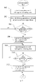
- Fig. 5 is a schematic diagram of the procedure by which the control apparatus 4 subjects the reflow furnace 1 shown in fig. 1A to temperature control.
- a program of the flow chart shown in fig. 5 is stored in the memory 414 of the control apparatus 4; the temperature control procedure is intended to regulate the temperature of each sub-region in the heating zone 10. For example, when soldering of a circuit board of a first type which needs to be heated to a higher temperature has ended, a circuit board of a second type which needs to be heated to a lower temperature will be soldered.
- the reflow furnace 1 must be cooled; activation of the cooling system 2 can accelerate the cooling of the reflow furnace 1. During cooling, the reflow furnace 1 is not operational.
- a set temperature of each sub-region is preset according to different soldering process requirements, and stored in the memory 414.
- the temperature of at least one of the sub-regions of the heating zone 10 is higher than the set temperature of this sub-region, by activating the blowing apparatus 64 connected to the gas intake pipeline 22 corresponding to this sub-region, the gas intake valve apparatus 42 of the gas intake pipeline 22 corresponding to this sub-region, the exhaust apparatus 66 and the gas discharge valve apparatus 44, air at a lower temperature in the environment is rapidly conveyed into the hearth, thereby rapidly lowering the temperature of this sub-region, and reducing the time needed to wait for the reflow furnace 1 to cool.
- step 502 the temperature sensors 74 detect the temperatures of all of the sub-regions in the heating zone 10.
- the processor 404 then shifts operation to step 503.
- step 503 the processor 404 closes the gas intake valve apparatuses 42, blowing apparatuses 64, gas discharge valve apparatuses 44 and exhaust apparatus 66. The processor 404 then shifts operation to step 504.
- step 504 if the temperature of each sub-region is not higher than the set temperature, then the control procedure is ended; if the temperature of at least one sub-region is higher than the set temperature, the processor 404 shifts operation to step 506.
- step 506 the processor 404 opens the gas intake valve apparatus 42 corresponding to the sub-region higher than the set temperature, the blowing apparatus 64, the gas discharge valve apparatus 44 and the blowing apparatus 66. The processor 404 then shifts operation to step 508.
- step 508 the temperature sensors 74 detect the temperatures of all of the sub-regions in the heating zone 10.
- the processor 404 then shifts operation to step 510.
- step 510 if the temperature of at least one sub-region is higher than the set temperature, the processor 404 shifts operation to step 508; if the temperature of each sub-region is not higher than the set temperature, the processor 404 shifts operation to step 512.
- step 512 the processor 404 closes the gas intake valve apparatus 42, blowing apparatus 64, gas discharge valve apparatus 44 and exhaust apparatus 66. The processor 404 then ends the control procedure.
- the blowing apparatus 64 and the exhaust apparatus 66 are sources of motive power, the exhaust apparatus 66 is more specifically a fan.
Landscapes
- Engineering & Computer Science (AREA)
- Mechanical Engineering (AREA)
- General Engineering & Computer Science (AREA)
- Environmental & Geological Engineering (AREA)
- Manufacturing & Machinery (AREA)
- Microelectronics & Electronic Packaging (AREA)
- Electric Connection Of Electric Components To Printed Circuits (AREA)
- Waste-Gas Treatment And Other Accessory Devices For Furnaces (AREA)
- Furnace Details (AREA)
Description
- The present application relates to the field of reflow furnaces, in particular to a cooling system for a reflow furnace.
- In a reflow furnace, different circuit boards need different heating temperatures in order to deposit solder paste (e.g. tin paste) in selected regions on the circuit board. Thus, the reflow furnace must provide different heating temperatures for different circuit boards. Patent documents
US 6 576 030 B2 ,EP 0 999 007 A1 ,CN 106 017 109 A andWO 2019/204623 A1 relate to a reflow furnace configured to regulated the heat flux applied on the treated solid pieces. - The present application provides a reflow furnace cooling system, to shorten the time taken for the reflow furnace to change from a higher heating temperature to a lower heating temperature.
- In order to solve the abovementionned problems, a cooling system for a reflow furnace is disclosed in appended claims 1-12.
- The cooling system of the present application can accelerate the cooling of the heating zone in the reflow furnace, in order to shorten the time taken for the reflow furnace to change from a higher heating temperature to a lower heating temperature.
- These and other features and advantages of the present application can be better understood by reading the following detailed explanation with reference to the accompanying drawings; throughout the drawings, identical drawing labels indicate identical components, wherein:
-
Fig. 1A is a simplified system diagram of a cooling system in an embodiment of the present application. -
Figs. 1B - 1C are simplified system diagrams of cooling systems in two other embodiments of the present application. -
Fig. 2 is a simplified system diagram of a cooling system in another embodiment of the present application. -
Fig. 3 is a schematic diagram of a control component and control connections of the cooling system shown infig. 1A . -
Fig. 4 is a simplified schematic diagram of one embodiment of the control apparatus infig. 3 . -
Fig. 5 is a schematic diagram of the procedure by which the control apparatus subjects the reflow furnace shown infig. 1A to temperature control. - Various particular embodiments of the present application are described below with reference to the accompanying drawings, which form part of this Description. In the drawings below, identical drawing numerals are used for identical components, and similar drawing numerals are used for similar components.
-
Fig. 1A is a simplified system diagram of acooling system 2 in an embodiment of the present application. As shown infig. 1A , thecooling system 2 comprises a reflow furnace 1. The reflow furnace 1 comprises aheating zone 10, a separatinggas discharge zone 16 and acooling zone 18. The separatinggas discharge zone 16 is disposed between theheating zone 10 and thecooling zone 18, and used to separate theheating zone 10 and thecooling zone 18 when the reflow furnace 1 is operating, in order to prevent the transmission of heat of theheating zone 10 into thecooling zone 18. A hearth (not shown) runs through theheating zone 10, the separatinggas discharge zone 16 and thecooling zone 18; theheating zone 10, the separatinggas discharge zone 16 and thecooling zone 18 are all in fluid communication with the hearth. Theheating zone 10 and thecooling zone 18 may each comprise multiple sub-regions, each of the sub-regions being in fluid communication with each other. In the embodiment shown infig. 1A , theheating zone 10 comprises ten sub-regions. The ten sub-regions comprise acolder zone 12 and ahotter zone 14. The temperature of thehotter zone 14 is higher than the temperature of thecolder zone 12. Thecolder zone 12 comprises twopreheating zones 17. Thehotter zone 14 comprises foureven temperature zones 13 and fourpeak value zones 15. Thepreheating zones 17, the eventemperature zones 13 and thepeak value zones 15 are arranged adjacently. In thepreheating zones 17 and theeven temperature zones 13, a circuit board can be heated gradually, and a portion of flux in solder paste on the circuit board will be gasified. In thepeak value zone 15, the circuit board continues to be heated, and the solder paste melts. The circuit board then passes through the separatinggas discharge zone 16 and is then conveyed into thecooling zone 18. Thecooling zone 18 comprises four sub-regions. In thecooling zone 18, the solder paste is cooled in soldering regions of the circuit board and cures, thereby connecting electronic elements to the circuit board. Each sub-region in theheating zone 10 is provided with a communication port. Specifically, each sub-region of thecolder zone 12 is provided with agas discharge port 8, for discharging gas contained in thecolder zone 12 out of the reflow furnace 1. Each sub-region in thehotter zone 14 is provided with agas inlet 6, for causing gas to enter the reflow furnace 1. - The
cooling system 2 further comprises twogas intake pipelines 22 and two blowingapparatuses 64. Each of the twogas intake pipelines 22 comprises one branch gasintake inlet pipe 84 and four branch gasintake outlet pipes 82. One end of one branch gasintake inlet pipe 84 is connected to one end of each of four branch gasintake outlet pipes 82. Another end of the branch gasintake inlet pipe 84 is aninlet 28, for connecting to a corresponding one of the blowingapparatuses 64. Another end of each of four branch gasintake outlet pipes 82 is anoutlet 24, for connecting to a corresponding one of fourgas inlets 6. Specifically, each of fouroutlets 24 in onegas intake pipeline 22 is connected to acorresponding gas inlet 6 in the four eventemperature zones 13. Each of fouroutlets 24 in the othergas intake pipeline 22 is connected to acorresponding gas inlet 6 in the fourpeak value zones 15. Thecooling system 2 further comprises eight gasintake valve apparatuses 42. Each of the eight gasintake valve apparatuses 42 is disposed on a corresponding one of the eight branch gasintake outlet pipes 82. - The
cooling system 2 further comprises agas discharge pipeline 32 and anexhaust apparatus 66. Thegas discharge pipeline 32 comprises two branch gasdischarge inlet pipes 72 and one branch gasdischarge outlet pipe 74; one end of each of the two branch gasdischarge inlet pipes 72 is connected to one end of the branch gasdischarge outlet pipe 74. Another end of each of the two branch gasdischarge inlet pipes 72 is aninlet 36, for connecting to a corresponding one of the twogas discharge ports 8 of the twocolder zones 12. Another end of the branch gasdischarge outlet pipe 74 is anoutlet 38, for connecting to theexhaust apparatus 66. Thecooling system 2 further comprises two gasdischarge valve apparatuses 44. Each of the two gasdischarge valve apparatuses 44 is disposed on a corresponding one of the two branch gasdischarge inlet pipes 72. - The arrows in
fig. 1A show the flow direction of air in the pipelines when the blowingapparatuses 64, theexhaust apparatus 66, the gasintake valve apparatuses 42 and the gasdischarge valve apparatuses 44 are all open. -
Figs. 1B - 1C are simplified system diagrams ofcooling systems 2 in two other embodiments of the present application, and are intended to show different positions of arrangement of the gasintake valve apparatuses 42 and the gas discharge valve apparatus(es) 44. Apart from the positions of arrangement of the gasintake valve apparatuses 42 and the gas discharge valve apparatus(es) 44 being different, the disposition of other components is the same as infig. 1A in each case, so is not described again superfluously here. As shown infig. 1B , in one embodiment, the gasintake valve apparatus 42 is disposed between theoutlet 24 of thegas intake pipeline 22 and thegas inlet 6; the gasdischarge valve apparatus 44 is disposed between theinlet 36 of thegas discharge pipeline 32 and thegas discharge port 8. As shown infig. 1C , in another embodiment, the gasintake valve apparatus 42 is disposed between theinlet 28 of thegas intake pipeline 22 and the blowingapparatus 64; the gasdischarge valve apparatus 44 is disposed between theoutlet 38 of thegas discharge pipeline 32 and theexhaust apparatus 66. -
Fig. 2 is a simplified system diagram of acooling system 2 in another embodiment of the present application, and is intended to show a different manner of arranginggas intake pipelines 22, blowingapparatuses 64,gas discharge pipelines 32 andexhaust apparatuses 66 in thecooling system 2. As shown infig. 2 , thecooling system 2 comprises eightgas intake pipelines 22, eight blowingapparatuses 64 and eight gasintake valve apparatuses 42. Each of the eight blowingapparatuses 64 is connected to a corresponding one of eightgas inlets 6 via a corresponding one of the eightgas intake pipelines 22. Each of the eight gasintake valve apparatuses 42 is disposed on a corresponding one of the eightgas intake pipelines 22. Thecooling system 2 further comprises twogas discharge pipelines 32, twoexhaust apparatuses 66 and two gasdischarge valve apparatuses 44. Each of the twoexhaust apparatuses 66 is connected to a corresponding one of twogas discharge ports 8 via a corresponding one of the twogas discharge pipelines 32. Each of the two gasdischarge valve apparatuses 44 is disposed on a corresponding one of the twogas discharge pipelines 32. - Those skilled in the art will understand that the number of sub-regions in the
heating zone 10 and thecooling zone 18 of the reflow furnace 1, and the number of sub-regions in thecolder zone 12 and thehotter zone 14, etc., can change according to the product to be soldered, and are not limited to the embodiments shown infigs. 1A - 2 . It must also be explained that thegas intake pipeline 22, the blowingapparatus 64, thegas discharge pipeline 32 and theexhaust apparatus 66 can change according to the setting of the reflow furnace 1, and are not restricted in terms of quantity or manner of connection, only being required to lead air into and out of the hearth and accelerate the flow of air in the hearth. -
Fig. 3 is a schematic diagram of a control component (comprising a control apparatus 4) and control connections of thecooling system 2 shown infig. 1A . As shown infig. 3 , thecooling system 2 further comprises thecontrol apparatus 4 and a temperature detection apparatus. The temperature detection apparatus is configured to be used for detecting the temperature in each sub-region in theheating zone 10. As an example, the temperature detection apparatus comprises tentemperature sensors 74. Thecontrol apparatus 4 is configured to be able to control the blowingapparatuses 64, theexhaust apparatus 66, the gasdischarge valve apparatuses 44 and the gasintake valve apparatuses 42 according to the temperatures detected by thetemperature sensors 74. Thecontrol apparatus 4 is in communicative connection with the blowingapparatuses 64, theexhaust apparatus 66, the gasdischarge valve apparatuses 44 and the gasintake valve apparatuses 42. -
Fig. 4 is a simplified schematic diagram of one unclaimed embodiment of thecontrol apparatus 4 infig. 3 . As shown infig. 4 , thecontrol apparatus 4 comprises abus 402, aprocessor 404, aninput interface 406, anoutput interface 408, and amemory 414 having acontrol program 416. All of the components in thecontrol apparatus 4, including theprocessor 404, theinput interface 406, theoutput interface 408 and thememory 414, are in communicative connection with thebus 402, such that theprocessor 404 is able to control the operation of theinput interface 406, theoutput interface 408 and thememory 414. Specifically, thememory 414 is used for storing programs, instructions and data; theprocessor 404 reads programs, instructions and data from thememory 414, and can write data into thememory 414. - The
input interface 406 receives signals and data from outside via a connectingline 418, including signals and data sent from thetemperature sensors 74. Theoutput interface 408 transmits control signals to the outside via a connectingline 422, including the transmission of opening and closing control signals to the blowingapparatuses 64, theexhaust apparatus 66, the gasdischarge valve apparatuses 44 and the gasintake valve apparatuses 42. The control program and data such as a preset temperature target set value are stored in thememory 414 of thecontrol apparatus 4. Various parameters may be preset in a production manufacturing project, or set during use by manual input or data import. -
Fig. 5 is a schematic diagram of the procedure by which thecontrol apparatus 4 subjects the reflow furnace 1 shown infig. 1A to temperature control. A program of the flow chart shown infig. 5 is stored in thememory 414 of thecontrol apparatus 4; the temperature control procedure is intended to regulate the temperature of each sub-region in theheating zone 10. For example, when soldering of a circuit board of a first type which needs to be heated to a higher temperature has ended, a circuit board of a second type which needs to be heated to a lower temperature will be soldered. At this time, the reflow furnace 1 must be cooled; activation of thecooling system 2 can accelerate the cooling of the reflow furnace 1. During cooling, the reflow furnace 1 is not operational. A set temperature of each sub-region is preset according to different soldering process requirements, and stored in thememory 414. When the temperature of at least one of the sub-regions of theheating zone 10 is higher than the set temperature of this sub-region, by activating the blowingapparatus 64 connected to thegas intake pipeline 22 corresponding to this sub-region, the gasintake valve apparatus 42 of thegas intake pipeline 22 corresponding to this sub-region, theexhaust apparatus 66 and the gasdischarge valve apparatus 44, air at a lower temperature in the environment is rapidly conveyed into the hearth, thereby rapidly lowering the temperature of this sub-region, and reducing the time needed to wait for the reflow furnace 1 to cool. - As shown in
fig. 5 , instep 502, thetemperature sensors 74 detect the temperatures of all of the sub-regions in theheating zone 10. Theprocessor 404 then shifts operation to step 503. - In
step 503, theprocessor 404 closes the gasintake valve apparatuses 42, blowingapparatuses 64, gasdischarge valve apparatuses 44 andexhaust apparatus 66. Theprocessor 404 then shifts operation to step 504. - In
step 504, if the temperature of each sub-region is not higher than the set temperature, then the control procedure is ended; if the temperature of at least one sub-region is higher than the set temperature, theprocessor 404 shifts operation to step 506. - In
step 506, theprocessor 404 opens the gasintake valve apparatus 42 corresponding to the sub-region higher than the set temperature, the blowingapparatus 64, the gasdischarge valve apparatus 44 and the blowingapparatus 66. Theprocessor 404 then shifts operation to step 508. - In
step 508, thetemperature sensors 74 detect the temperatures of all of the sub-regions in theheating zone 10. Theprocessor 404 then shifts operation to step 510. - In
step 510, if the temperature of at least one sub-region is higher than the set temperature, theprocessor 404 shifts operation to step 508; if the temperature of each sub-region is not higher than the set temperature, theprocessor 404 shifts operation to step 512. - In
step 512, theprocessor 404 closes the gasintake valve apparatus 42, blowingapparatus 64, gasdischarge valve apparatus 44 andexhaust apparatus 66. Theprocessor 404 then ends the control procedure. - The blowing
apparatus 64 and theexhaust apparatus 66 are sources of motive power, theexhaust apparatus 66 is more specifically a fan. - It should be understood that the attached claims are intended to cover all of the abovementioned improvements and changes which fall within the scope of the present application.
Claims (12)
- A cooling system (2) for a reflow furnace (1), the reflow furnace (1) comprising a heating zone (10), and the cooling system (2) configured to regulate a temperature of the heating zone (10), wherein the cooling system (2) comprises:a blowing apparatus (64);at least one gas inlet (6) and at least one gas discharge port (8), the at least one gas inlet (6) and the at least one gas discharge port (8) being disposed on the heating zone (10);at least one gas intake pipeline (22), an inlet (28) of the at least one gas intake pipeline (22) being connected to the blowing apparatus (64), an outlet (24) of the at least one gas intake pipeline (22) being connected to the at least one gas inlet (6), the at least one gas intake pipeline (22) being able to controllably establish fluid communication between the blowing apparatus (64) and the at least one gas inlet (6); andat least one gas discharge pipeline (32), an inlet (36) of the at least one gas discharge pipeline (32) being connected to the at least one gas discharge port (8), an outlet (38) of the at least one gas discharge pipeline (32) being connected to the outside, and the at least one gas discharge pipeline (32) being able to controllably establish fluid communication between the at least one gas discharge port (8) and the outside,wherein the outlet (38) of the at least one gas discharge pipeline (32) is configured to connect to an exhaust apparatus (66), the at least one gas discharge pipeline (32) can controllably connect the at least one gas discharge port (8) to the exhaust apparatus (66), and the exhaust apparatus (66) is configured to discharge gas in the reflow furnace (1) to the outside, wherein the exhaust apparatus (66) is a fan.
- The cooling system (2) as claimed in claim 1, characterized in that:the at least one gas intake pipeline (22) is multiple gas intake pipelines, and the at least one gas inlet (6) is multiple gas inlets;the inlet (28) of each of the multiple gas intake pipelines (22) is connected to the blowing apparatus (64), the outlet (24) of each of the multiple gas intake pipelines (22) is connected to a corresponding one of the multiple gas inlets (6), and each of the multiple gas intake pipelines (22) can controllably establish fluid communication between the blowing apparatus (64) and a corresponding one of the multiple gas inlets (6).
- The cooling system (2) as claimed in claim 1, characterized in that:
the heating zone (10) comprises a colder zone (12) and a hotter zone (14), the temperature of the hotter zone (14) being higher than the temperature of the colder zone (12), the at least one gas inlet (6) being disposed at the hotter zone (14), and the at least one gas discharge port (8) being disposed at the colder zone (12). - The cooling system (2) as claimed in claim 1, characterized in that:
the blowing apparatus (64) comprises a fan. - The cooling system (2) as claimed in claim 2, characterized in that:
the blowing apparatus (64) comprises multiple fans, each of the multiple gas inlets (6) being controllably connected to a corresponding one of the multiple fans. - The cooling system (2) as claimed in claim 1, characterized by further comprising:
at least one gas intake valve apparatus (42), disposed between the at least one gas inlet (6) and the blowing apparatus (64). - The cooling system (2) as claimed in claim 6, characterized in that:
the at least one gas intake valve apparatus (42) is disposed on at least one gas intake pipeline (22). - The cooling system (2) as claimed in claim 6, characterized in that:
the at least one gas intake valve apparatus (42) is disposed between the at least one gas inlet (6) and the outlet (24) of the at least one gas intake pipeline (22). - The cooling system (2) as claimed in claim 6, characterized in that:
the at least one gas intake valve apparatus (42) is disposed between the blowing apparatus (64) and the inlet (28) of the at least one gas intake pipeline (22). - The cooling system (2) as claimed in claim 1, characterized by further comprising:
at least one gas discharge valve apparatus (44), disposed between the inlet (36) of the at least one gas discharge pipeline (32) and the at least one gas discharge port (8). - The cooling system (2) as claimed in any one of claims 7 - 10, characterized by further comprising:
a control apparatus (4), configured to control the blowing apparatus (64) and at least one gas intake valve apparatus (42). - The cooling system (2) as claimed in claim 11, characterized by further comprising:a temperature detection apparatus, configured to detect the temperature of the heating zone (10);the control apparatus (4) being able to control the blowing apparatus (64) and at least one gas intake valve apparatus (42) according to the temperature detected by the temperature detection apparatus.
Applications Claiming Priority (2)
| Application Number | Priority Date | Filing Date | Title |
|---|---|---|---|
| CN201810993604.9A CN110871299A (en) | 2018-08-29 | 2018-08-29 | Cooling system of reflow oven |
| PCT/US2019/048370 WO2020046959A1 (en) | 2018-08-29 | 2019-08-27 | A cooling system for a reflow furnace |
Publications (2)
| Publication Number | Publication Date |
|---|---|
| EP3844448A1 EP3844448A1 (en) | 2021-07-07 |
| EP3844448B1 true EP3844448B1 (en) | 2022-12-28 |
Family
ID=67876118
Family Applications (1)
| Application Number | Title | Priority Date | Filing Date |
|---|---|---|---|
| EP19765614.3A Active EP3844448B1 (en) | 2018-08-29 | 2019-08-27 | A cooling system for a reflow furnace |
Country Status (6)
| Country | Link |
|---|---|
| US (1) | US11679444B2 (en) |
| EP (1) | EP3844448B1 (en) |
| JP (1) | JP7402224B2 (en) |
| CN (1) | CN110871299A (en) |
| TW (1) | TWI848962B (en) |
| WO (1) | WO2020046959A1 (en) |
Families Citing this family (5)
| Publication number | Priority date | Publication date | Assignee | Title |
|---|---|---|---|---|
| HUE070720T2 (en) * | 2020-11-12 | 2025-06-28 | Senju Metal Industry Co | Soldering apparatus |
| CN114985861A (en) | 2021-03-01 | 2022-09-02 | 伊利诺斯工具制品有限公司 | Oxygen content detection system and control method thereof |
| DE102021129122B4 (en) * | 2021-11-09 | 2024-03-07 | Ersa Gmbh | Soldering system, especially reflow soldering system with cover and switchable suction channel |
| CN116160085A (en) * | 2021-11-25 | 2023-05-26 | 上海朗仕电子设备有限公司 | Air guide device for cooling hearth temperature of reflow oven |
| JP7384973B1 (en) * | 2022-08-08 | 2023-11-21 | 中外炉工業株式会社 | heat treatment furnace |
Citations (1)
| Publication number | Priority date | Publication date | Assignee | Title |
|---|---|---|---|---|
| WO2019204623A1 (en) * | 2018-04-20 | 2019-10-24 | Illinois Tool Works Inc. | Reflow oven and operation method thereof |
Family Cites Families (31)
| Publication number | Priority date | Publication date | Assignee | Title |
|---|---|---|---|---|
| JPS54139030U (en) * | 1978-03-22 | 1979-09-27 | ||
| KR910005959B1 (en) * | 1988-01-19 | 1991-08-09 | 니혼 덴네쯔 게이기 가부시끼가이샤 | Reflow soldering device |
| US5345061A (en) * | 1992-09-15 | 1994-09-06 | Vitronics Corporation | Convection/infrared solder reflow apparatus utilizing controlled gas flow |
| US5440101A (en) * | 1993-04-19 | 1995-08-08 | Research, Incorporated | Continuous oven with a plurality of heating zones |
| JPH07212028A (en) * | 1994-01-13 | 1995-08-11 | Matsushita Electric Ind Co Ltd | Reflow equipment |
| JP3454621B2 (en) * | 1995-09-30 | 2003-10-06 | 古河電気工業株式会社 | Inert gas atmosphere furnace |
| JP3636815B2 (en) * | 1996-05-15 | 2005-04-06 | 松下電器産業株式会社 | Reflow soldering equipment |
| US6146448A (en) * | 1998-11-02 | 2000-11-14 | Soltec B.V. | Flux management system for a solder reflow oven |
| EP1259772B1 (en) * | 2000-02-02 | 2009-11-11 | BTU International, Inc. | Modular furnace system |
| GB2375975B (en) * | 2001-05-30 | 2005-07-20 | Philip Arthur Mullins | Filtering apparatus |
| US6780225B2 (en) * | 2002-05-24 | 2004-08-24 | Vitronics Soltec, Inc. | Reflow oven gas management system and method |
| US8328551B2 (en) * | 2002-09-26 | 2012-12-11 | Btu International, Inc. | Convection furnace thermal profile enhancement |
| DE10350699B3 (en) * | 2003-10-30 | 2005-06-30 | Rehm Anlagenbau Gmbh | Method and apparatus for reflow soldering with volume flow control |
| CN102049587A (en) * | 2009-11-02 | 2011-05-11 | 西安中科麦特电子技术设备有限公司 | Temperature control system for large temperature difference adjustment of reflow soldering machine and temperature control method |
| US8196799B2 (en) * | 2010-06-28 | 2012-06-12 | Illinois Tool Works Inc. | Compression box for reflow oven heating with a pressurizing plate |
| CN201793673U (en) * | 2010-08-25 | 2011-04-13 | 中冶南方(武汉)威仕工业炉有限公司 | Automatic cooling system for heat treatment furnace |
| JP5343988B2 (en) * | 2011-01-31 | 2013-11-13 | 株式会社デンソー | Brazing equipment |
| CN102229015B (en) * | 2011-06-28 | 2013-08-21 | 维多利绍德机械科技(苏州)有限公司 | Reflow soldering air cooling system |
| JP5694546B2 (en) * | 2011-09-15 | 2015-04-01 | 富士通テレコムネットワークス株式会社 | Reflow soldering apparatus and method |
| EP3053691A1 (en) * | 2015-02-04 | 2016-08-10 | Illinois Tool Works Inc. | Reflow soldering oven with enhanced gas purification system |
| CN105174257B (en) * | 2015-05-31 | 2018-02-23 | 浙江阿佩克斯能源科技有限公司 | A kind of Kun formulas multiple temperature sections continuous production tunnel kiln |
| CN106017109A (en) * | 2016-05-16 | 2016-10-12 | 郭泗恒 | Energy-saving process of blast furnace circulating water cooling system with upper tower pumps |
| CN106695048A (en) * | 2016-12-21 | 2017-05-24 | 通富微电子股份有限公司 | Reflow soldering furnace and control system thereof |
| CN207139050U (en) * | 2017-09-21 | 2018-03-27 | 成都大学 | A kind of multi-functional soldering oven |
| CN207907718U (en) * | 2018-01-25 | 2018-09-25 | 东莞市创威自动化科技有限公司 | The heat energy recycling structure of hot air type reflow soldering |
| JP6746673B2 (en) * | 2018-01-29 | 2020-08-26 | 株式会社タムラ製作所 | Gas purification device and transfer heating device |
| CN110385496B (en) * | 2018-04-20 | 2022-09-30 | 伊利诺斯工具制品有限公司 | Reflow oven and method of operating the same |
| CN110874106B (en) * | 2018-08-31 | 2022-09-02 | 伊利诺斯工具制品有限公司 | Gas control system and method for reflow oven |
| CN210172742U (en) * | 2019-03-29 | 2020-03-24 | 深圳市劲拓自动化设备股份有限公司 | Reflow soldering equipment with automatic cooling function |
| CN210718617U (en) * | 2019-09-30 | 2020-06-09 | 漳州明德工贸有限公司 | Battery material pushed slab kiln capable of realizing hot gas circulation |
| CN112975033B (en) * | 2019-12-12 | 2025-08-19 | 伊利诺斯工具制品有限公司 | Reflow oven |
-
2018
- 2018-08-29 CN CN201810993604.9A patent/CN110871299A/en active Pending
-
2019
- 2019-07-17 TW TW108125163A patent/TWI848962B/en active
- 2019-08-27 US US17/271,461 patent/US11679444B2/en active Active
- 2019-08-27 EP EP19765614.3A patent/EP3844448B1/en active Active
- 2019-08-27 JP JP2021510913A patent/JP7402224B2/en active Active
- 2019-08-27 WO PCT/US2019/048370 patent/WO2020046959A1/en not_active Ceased
Patent Citations (1)
| Publication number | Priority date | Publication date | Assignee | Title |
|---|---|---|---|---|
| WO2019204623A1 (en) * | 2018-04-20 | 2019-10-24 | Illinois Tool Works Inc. | Reflow oven and operation method thereof |
Also Published As
| Publication number | Publication date |
|---|---|
| US20210346969A1 (en) | 2021-11-11 |
| EP3844448A1 (en) | 2021-07-07 |
| TWI848962B (en) | 2024-07-21 |
| WO2020046959A1 (en) | 2020-03-05 |
| JP2021536560A (en) | 2021-12-27 |
| CN110871299A (en) | 2020-03-10 |
| US11679444B2 (en) | 2023-06-20 |
| TW202012084A (en) | 2020-04-01 |
| JP7402224B2 (en) | 2023-12-20 |
Similar Documents
| Publication | Publication Date | Title |
|---|---|---|
| US11679444B2 (en) | Cooling system for a reflow furnace | |
| EP3781886B1 (en) | Reflow oven and operation method thereof | |
| US12385694B2 (en) | Reflow furnace | |
| US7666345B2 (en) | Method and apparatus for melting metal | |
| JPH0434095B2 (en) | ||
| US20040063058A1 (en) | Convection furnace thermal profile enhancement | |
| CN103286408A (en) | Heat source system | |
| WO2019204623A1 (en) | Reflow oven and operation method thereof | |
| US20100145523A1 (en) | Overheat Detection System | |
| US20060082034A1 (en) | Method and apparatus for automatically controlling temperature in a furnace system | |
| CN1301534C (en) | Prevention methods for abnormal events of semiconductor furnace tube temperature and gas flow | |
| CN209386553U (en) | A kind of temperature controllable air-heater and hot blast feeding system | |
| CN106017105A (en) | Furnace drying method of industrial furnace module and furnace drying device of furnace drying method | |
| CN201012418Y (en) | Soldering district heating mechanism of the brazier | |
| CN101360582A (en) | Systems and methods of controlling supplementary equipment | |
| CN213021043U (en) | Gradient temperature control system of curing oven | |
| JP3585067B2 (en) | Heat deoiler | |
| CN101041196A (en) | Heating device of the heating braze welding region of the interval type braze welding furnace | |
| EP3672754B1 (en) | A reflow oven with a zeolite box, and a method of recovering gas with such zeolite box | |
| CN209655578U (en) | A kind of register of conduction oil | |
| CN220874955U (en) | Precise temperature control air mixing device | |
| CN2919163Y (en) | Fast cooling device of solar cell substrate firing furnace | |
| CN120575003A (en) | Hot blast stove system and control method thereof | |
| WO2025188962A8 (en) | Multiple flow path gas inlet with integrated heating and temperature control | |
| CN118729794A (en) | Temperature control device and control method for glass kiln flue gas treatment |
Legal Events
| Date | Code | Title | Description |
|---|---|---|---|
| STAA | Information on the status of an ep patent application or granted ep patent |
Free format text: STATUS: UNKNOWN |
|
| STAA | Information on the status of an ep patent application or granted ep patent |
Free format text: STATUS: THE INTERNATIONAL PUBLICATION HAS BEEN MADE |
|
| STAA | Information on the status of an ep patent application or granted ep patent |
Free format text: STATUS: REQUEST FOR EXAMINATION WAS MADE |
|
| PUAI | Public reference made under article 153(3) epc to a published international application that has entered the european phase |
Free format text: ORIGINAL CODE: 0009012 |
|
| 17P | Request for examination filed |
Effective date: 20210211 |
|
| AK | Designated contracting states |
Kind code of ref document: A1 Designated state(s): AL AT BE BG CH CY CZ DE DK EE ES FI FR GB GR HR HU IE IS IT LI LT LU LV MC MK MT NL NO PL PT RO RS SE SI SK SM TR |
|
| DAV | Request for validation of the european patent (deleted) | ||
| DAX | Request for extension of the european patent (deleted) | ||
| STAA | Information on the status of an ep patent application or granted ep patent |
Free format text: STATUS: EXAMINATION IS IN PROGRESS |
|
| 17Q | First examination report despatched |
Effective date: 20211213 |
|
| RIC1 | Information provided on ipc code assigned before grant |
Ipc: F27D 9/00 20060101ALN20220706BHEP Ipc: F27B 9/12 20060101ALN20220706BHEP Ipc: H05K 3/34 20060101ALI20220706BHEP Ipc: F27D 17/00 20060101ALI20220706BHEP Ipc: F27B 9/40 20060101ALI20220706BHEP Ipc: F27B 9/02 20060101AFI20220706BHEP |
|
| GRAP | Despatch of communication of intention to grant a patent |
Free format text: ORIGINAL CODE: EPIDOSNIGR1 |
|
| STAA | Information on the status of an ep patent application or granted ep patent |
Free format text: STATUS: GRANT OF PATENT IS INTENDED |
|
| INTG | Intention to grant announced |
Effective date: 20220825 |
|
| RAP3 | Party data changed (applicant data changed or rights of an application transferred) |
Owner name: ILLINOIS TOOL WORKS INC. |
|
| RIN1 | Information on inventor provided before grant (corrected) |
Inventor name: ZHANG, DONG Inventor name: SHU, PENG Inventor name: YAN, SHENGHU |
|
| GRAS | Grant fee paid |
Free format text: ORIGINAL CODE: EPIDOSNIGR3 |
|
| GRAA | (expected) grant |
Free format text: ORIGINAL CODE: 0009210 |
|
| STAA | Information on the status of an ep patent application or granted ep patent |
Free format text: STATUS: THE PATENT HAS BEEN GRANTED |
|
| AK | Designated contracting states |
Kind code of ref document: B1 Designated state(s): AL AT BE BG CH CY CZ DE DK EE ES FI FR GB GR HR HU IE IS IT LI LT LU LV MC MK MT NL NO PL PT RO RS SE SI SK SM TR |
|
| REG | Reference to a national code |
Ref country code: GB Ref legal event code: FG4D |
|
| REG | Reference to a national code |
Ref country code: CH Ref legal event code: EP |
|
| REG | Reference to a national code |
Ref country code: DE Ref legal event code: R096 Ref document number: 602019023716 Country of ref document: DE |
|
| REG | Reference to a national code |
Ref country code: AT Ref legal event code: REF Ref document number: 1540754 Country of ref document: AT Kind code of ref document: T Effective date: 20230115 |
|
| REG | Reference to a national code |
Ref country code: IE Ref legal event code: FG4D |
|
| REG | Reference to a national code |
Ref country code: LT Ref legal event code: MG9D |
|
| PG25 | Lapsed in a contracting state [announced via postgrant information from national office to epo] |
Ref country code: SE Free format text: LAPSE BECAUSE OF FAILURE TO SUBMIT A TRANSLATION OF THE DESCRIPTION OR TO PAY THE FEE WITHIN THE PRESCRIBED TIME-LIMIT Effective date: 20221228 Ref country code: NO Free format text: LAPSE BECAUSE OF FAILURE TO SUBMIT A TRANSLATION OF THE DESCRIPTION OR TO PAY THE FEE WITHIN THE PRESCRIBED TIME-LIMIT Effective date: 20230328 Ref country code: LT Free format text: LAPSE BECAUSE OF FAILURE TO SUBMIT A TRANSLATION OF THE DESCRIPTION OR TO PAY THE FEE WITHIN THE PRESCRIBED TIME-LIMIT Effective date: 20221228 Ref country code: FI Free format text: LAPSE BECAUSE OF FAILURE TO SUBMIT A TRANSLATION OF THE DESCRIPTION OR TO PAY THE FEE WITHIN THE PRESCRIBED TIME-LIMIT Effective date: 20221228 |
|
| REG | Reference to a national code |
Ref country code: NL Ref legal event code: MP Effective date: 20221228 |
|
| REG | Reference to a national code |
Ref country code: AT Ref legal event code: MK05 Ref document number: 1540754 Country of ref document: AT Kind code of ref document: T Effective date: 20221228 |
|
| PG25 | Lapsed in a contracting state [announced via postgrant information from national office to epo] |
Ref country code: RS Free format text: LAPSE BECAUSE OF FAILURE TO SUBMIT A TRANSLATION OF THE DESCRIPTION OR TO PAY THE FEE WITHIN THE PRESCRIBED TIME-LIMIT Effective date: 20221228 Ref country code: LV Free format text: LAPSE BECAUSE OF FAILURE TO SUBMIT A TRANSLATION OF THE DESCRIPTION OR TO PAY THE FEE WITHIN THE PRESCRIBED TIME-LIMIT Effective date: 20221228 Ref country code: HR Free format text: LAPSE BECAUSE OF FAILURE TO SUBMIT A TRANSLATION OF THE DESCRIPTION OR TO PAY THE FEE WITHIN THE PRESCRIBED TIME-LIMIT Effective date: 20221228 Ref country code: GR Free format text: LAPSE BECAUSE OF FAILURE TO SUBMIT A TRANSLATION OF THE DESCRIPTION OR TO PAY THE FEE WITHIN THE PRESCRIBED TIME-LIMIT Effective date: 20230329 |
|
| PG25 | Lapsed in a contracting state [announced via postgrant information from national office to epo] |
Ref country code: NL Free format text: LAPSE BECAUSE OF FAILURE TO SUBMIT A TRANSLATION OF THE DESCRIPTION OR TO PAY THE FEE WITHIN THE PRESCRIBED TIME-LIMIT Effective date: 20221228 |
|
| P01 | Opt-out of the competence of the unified patent court (upc) registered |
Effective date: 20230606 |
|
| PG25 | Lapsed in a contracting state [announced via postgrant information from national office to epo] |
Ref country code: SM Free format text: LAPSE BECAUSE OF FAILURE TO SUBMIT A TRANSLATION OF THE DESCRIPTION OR TO PAY THE FEE WITHIN THE PRESCRIBED TIME-LIMIT Effective date: 20221228 Ref country code: RO Free format text: LAPSE BECAUSE OF FAILURE TO SUBMIT A TRANSLATION OF THE DESCRIPTION OR TO PAY THE FEE WITHIN THE PRESCRIBED TIME-LIMIT Effective date: 20221228 Ref country code: PT Free format text: LAPSE BECAUSE OF FAILURE TO SUBMIT A TRANSLATION OF THE DESCRIPTION OR TO PAY THE FEE WITHIN THE PRESCRIBED TIME-LIMIT Effective date: 20230428 Ref country code: ES Free format text: LAPSE BECAUSE OF FAILURE TO SUBMIT A TRANSLATION OF THE DESCRIPTION OR TO PAY THE FEE WITHIN THE PRESCRIBED TIME-LIMIT Effective date: 20221228 Ref country code: EE Free format text: LAPSE BECAUSE OF FAILURE TO SUBMIT A TRANSLATION OF THE DESCRIPTION OR TO PAY THE FEE WITHIN THE PRESCRIBED TIME-LIMIT Effective date: 20221228 Ref country code: CZ Free format text: LAPSE BECAUSE OF FAILURE TO SUBMIT A TRANSLATION OF THE DESCRIPTION OR TO PAY THE FEE WITHIN THE PRESCRIBED TIME-LIMIT Effective date: 20221228 Ref country code: AT Free format text: LAPSE BECAUSE OF FAILURE TO SUBMIT A TRANSLATION OF THE DESCRIPTION OR TO PAY THE FEE WITHIN THE PRESCRIBED TIME-LIMIT Effective date: 20221228 |
|
| PG25 | Lapsed in a contracting state [announced via postgrant information from national office to epo] |
Ref country code: SK Free format text: LAPSE BECAUSE OF FAILURE TO SUBMIT A TRANSLATION OF THE DESCRIPTION OR TO PAY THE FEE WITHIN THE PRESCRIBED TIME-LIMIT Effective date: 20221228 Ref country code: PL Free format text: LAPSE BECAUSE OF FAILURE TO SUBMIT A TRANSLATION OF THE DESCRIPTION OR TO PAY THE FEE WITHIN THE PRESCRIBED TIME-LIMIT Effective date: 20221228 Ref country code: IS Free format text: LAPSE BECAUSE OF FAILURE TO SUBMIT A TRANSLATION OF THE DESCRIPTION OR TO PAY THE FEE WITHIN THE PRESCRIBED TIME-LIMIT Effective date: 20230428 Ref country code: AL Free format text: LAPSE BECAUSE OF FAILURE TO SUBMIT A TRANSLATION OF THE DESCRIPTION OR TO PAY THE FEE WITHIN THE PRESCRIBED TIME-LIMIT Effective date: 20221228 |
|
| REG | Reference to a national code |
Ref country code: DE Ref legal event code: R097 Ref document number: 602019023716 Country of ref document: DE |
|
| PG25 | Lapsed in a contracting state [announced via postgrant information from national office to epo] |
Ref country code: DK Free format text: LAPSE BECAUSE OF FAILURE TO SUBMIT A TRANSLATION OF THE DESCRIPTION OR TO PAY THE FEE WITHIN THE PRESCRIBED TIME-LIMIT Effective date: 20221228 |
|
| PLBE | No opposition filed within time limit |
Free format text: ORIGINAL CODE: 0009261 |
|
| STAA | Information on the status of an ep patent application or granted ep patent |
Free format text: STATUS: NO OPPOSITION FILED WITHIN TIME LIMIT |
|
| 26N | No opposition filed |
Effective date: 20230929 |
|
| PG25 | Lapsed in a contracting state [announced via postgrant information from national office to epo] |
Ref country code: SI Free format text: LAPSE BECAUSE OF FAILURE TO SUBMIT A TRANSLATION OF THE DESCRIPTION OR TO PAY THE FEE WITHIN THE PRESCRIBED TIME-LIMIT Effective date: 20221228 |
|
| PG25 | Lapsed in a contracting state [announced via postgrant information from national office to epo] |
Ref country code: MC Free format text: LAPSE BECAUSE OF FAILURE TO SUBMIT A TRANSLATION OF THE DESCRIPTION OR TO PAY THE FEE WITHIN THE PRESCRIBED TIME-LIMIT Effective date: 20221228 |
|
| REG | Reference to a national code |
Ref country code: CH Ref legal event code: PL |
|
| PG25 | Lapsed in a contracting state [announced via postgrant information from national office to epo] |
Ref country code: MC Free format text: LAPSE BECAUSE OF FAILURE TO SUBMIT A TRANSLATION OF THE DESCRIPTION OR TO PAY THE FEE WITHIN THE PRESCRIBED TIME-LIMIT Effective date: 20221228 |
|
| PG25 | Lapsed in a contracting state [announced via postgrant information from national office to epo] |
Ref country code: LU Free format text: LAPSE BECAUSE OF NON-PAYMENT OF DUE FEES Effective date: 20230827 |
|
| GBPC | Gb: european patent ceased through non-payment of renewal fee |
Effective date: 20230827 |
|
| PG25 | Lapsed in a contracting state [announced via postgrant information from national office to epo] |
Ref country code: LU Free format text: LAPSE BECAUSE OF NON-PAYMENT OF DUE FEES Effective date: 20230827 Ref country code: CH Free format text: LAPSE BECAUSE OF NON-PAYMENT OF DUE FEES Effective date: 20230831 |
|
| REG | Reference to a national code |
Ref country code: BE Ref legal event code: MM Effective date: 20230831 |
|
| REG | Reference to a national code |
Ref country code: IE Ref legal event code: MM4A |
|
| PG25 | Lapsed in a contracting state [announced via postgrant information from national office to epo] |
Ref country code: IT Free format text: LAPSE BECAUSE OF FAILURE TO SUBMIT A TRANSLATION OF THE DESCRIPTION OR TO PAY THE FEE WITHIN THE PRESCRIBED TIME-LIMIT Effective date: 20221228 |
|
| PG25 | Lapsed in a contracting state [announced via postgrant information from national office to epo] |
Ref country code: IE Free format text: LAPSE BECAUSE OF NON-PAYMENT OF DUE FEES Effective date: 20230827 |
|
| PG25 | Lapsed in a contracting state [announced via postgrant information from national office to epo] |
Ref country code: GB Free format text: LAPSE BECAUSE OF NON-PAYMENT OF DUE FEES Effective date: 20230827 |
|
| PG25 | Lapsed in a contracting state [announced via postgrant information from national office to epo] |
Ref country code: IE Free format text: LAPSE BECAUSE OF NON-PAYMENT OF DUE FEES Effective date: 20230827 Ref country code: GB Free format text: LAPSE BECAUSE OF NON-PAYMENT OF DUE FEES Effective date: 20230827 Ref country code: FR Free format text: LAPSE BECAUSE OF NON-PAYMENT OF DUE FEES Effective date: 20230831 |
|
| PG25 | Lapsed in a contracting state [announced via postgrant information from national office to epo] |
Ref country code: BE Free format text: LAPSE BECAUSE OF NON-PAYMENT OF DUE FEES Effective date: 20230831 |
|
| PG25 | Lapsed in a contracting state [announced via postgrant information from national office to epo] |
Ref country code: BG Free format text: LAPSE BECAUSE OF FAILURE TO SUBMIT A TRANSLATION OF THE DESCRIPTION OR TO PAY THE FEE WITHIN THE PRESCRIBED TIME-LIMIT Effective date: 20221228 |
|
| PG25 | Lapsed in a contracting state [announced via postgrant information from national office to epo] |
Ref country code: BG Free format text: LAPSE BECAUSE OF FAILURE TO SUBMIT A TRANSLATION OF THE DESCRIPTION OR TO PAY THE FEE WITHIN THE PRESCRIBED TIME-LIMIT Effective date: 20221228 |
|
| PG25 | Lapsed in a contracting state [announced via postgrant information from national office to epo] |
Ref country code: CY Free format text: LAPSE BECAUSE OF FAILURE TO SUBMIT A TRANSLATION OF THE DESCRIPTION OR TO PAY THE FEE WITHIN THE PRESCRIBED TIME-LIMIT; INVALID AB INITIO Effective date: 20190827 |
|
| PG25 | Lapsed in a contracting state [announced via postgrant information from national office to epo] |
Ref country code: HU Free format text: LAPSE BECAUSE OF FAILURE TO SUBMIT A TRANSLATION OF THE DESCRIPTION OR TO PAY THE FEE WITHIN THE PRESCRIBED TIME-LIMIT; INVALID AB INITIO Effective date: 20190827 |
|
| PGFP | Annual fee paid to national office [announced via postgrant information from national office to epo] |
Ref country code: DE Payment date: 20250827 Year of fee payment: 7 |
|
| PG25 | Lapsed in a contracting state [announced via postgrant information from national office to epo] |
Ref country code: TR Free format text: LAPSE BECAUSE OF FAILURE TO SUBMIT A TRANSLATION OF THE DESCRIPTION OR TO PAY THE FEE WITHIN THE PRESCRIBED TIME-LIMIT Effective date: 20221228 |