EP3843935B1 - Buffer block apparatuses and supporting apparatuses - Google Patents
Buffer block apparatuses and supporting apparatuses Download PDFInfo
- Publication number
- EP3843935B1 EP3843935B1 EP19853889.4A EP19853889A EP3843935B1 EP 3843935 B1 EP3843935 B1 EP 3843935B1 EP 19853889 A EP19853889 A EP 19853889A EP 3843935 B1 EP3843935 B1 EP 3843935B1
- Authority
- EP
- European Patent Office
- Prior art keywords
- node
- buffer block
- block apparatus
- assembly
- features
- Prior art date
- Legal status (The legal status is an assumption and is not a legal conclusion. Google has not performed a legal analysis and makes no representation as to the accuracy of the status listed.)
- Active
Links
Images











Classifications
-
- B—PERFORMING OPERATIONS; TRANSPORTING
- B25—HAND TOOLS; PORTABLE POWER-DRIVEN TOOLS; MANIPULATORS
- B25J—MANIPULATORS; CHAMBERS PROVIDED WITH MANIPULATION DEVICES
- B25J15/00—Gripping heads and other end effectors
- B25J15/0052—Gripping heads and other end effectors multiple gripper units or multiple end effectors
- B25J15/0061—Gripping heads and other end effectors multiple gripper units or multiple end effectors mounted on a modular gripping structure
-
- B—PERFORMING OPERATIONS; TRANSPORTING
- B25—HAND TOOLS; PORTABLE POWER-DRIVEN TOOLS; MANIPULATORS
- B25J—MANIPULATORS; CHAMBERS PROVIDED WITH MANIPULATION DEVICES
- B25J15/00—Gripping heads and other end effectors
- B25J15/08—Gripping heads and other end effectors having finger members
- B25J15/10—Gripping heads and other end effectors having finger members with three or more finger members
-
- B—PERFORMING OPERATIONS; TRANSPORTING
- B33—ADDITIVE MANUFACTURING TECHNOLOGY
- B33Y—ADDITIVE MANUFACTURING, i.e. MANUFACTURING OF THREE-DIMENSIONAL [3D] OBJECTS BY ADDITIVE DEPOSITION, ADDITIVE AGGLOMERATION OR ADDITIVE LAYERING, e.g. BY 3D PRINTING, STEREOLITHOGRAPHY OR SELECTIVE LASER SINTERING
- B33Y80/00—Products made by additive manufacturing
-
- B—PERFORMING OPERATIONS; TRANSPORTING
- B62—LAND VEHICLES FOR TRAVELLING OTHERWISE THAN ON RAILS
- B62D—MOTOR VEHICLES; TRAILERS
- B62D27/00—Connections between superstructure or understructure sub-units
- B62D27/02—Connections between superstructure or understructure sub-units rigid
- B62D27/023—Assembly of structural joints
-
- B—PERFORMING OPERATIONS; TRANSPORTING
- B22—CASTING; POWDER METALLURGY
- B22F—WORKING METALLIC POWDER; MANUFACTURE OF ARTICLES FROM METALLIC POWDER; MAKING METALLIC POWDER; APPARATUS OR DEVICES SPECIALLY ADAPTED FOR METALLIC POWDER
- B22F10/00—Additive manufacturing of workpieces or articles from metallic powder
- B22F10/20—Direct sintering or melting
- B22F10/25—Direct deposition of metal particles, e.g. direct metal deposition [DMD] or laser engineered net shaping [LENS]
-
- B—PERFORMING OPERATIONS; TRANSPORTING
- B22—CASTING; POWDER METALLURGY
- B22F—WORKING METALLIC POWDER; MANUFACTURE OF ARTICLES FROM METALLIC POWDER; MAKING METALLIC POWDER; APPARATUS OR DEVICES SPECIALLY ADAPTED FOR METALLIC POWDER
- B22F10/00—Additive manufacturing of workpieces or articles from metallic powder
- B22F10/20—Direct sintering or melting
- B22F10/28—Powder bed fusion, e.g. selective laser melting [SLM] or electron beam melting [EBM]
-
- B—PERFORMING OPERATIONS; TRANSPORTING
- B22—CASTING; POWDER METALLURGY
- B22F—WORKING METALLIC POWDER; MANUFACTURE OF ARTICLES FROM METALLIC POWDER; MAKING METALLIC POWDER; APPARATUS OR DEVICES SPECIALLY ADAPTED FOR METALLIC POWDER
- B22F10/00—Additive manufacturing of workpieces or articles from metallic powder
- B22F10/60—Treatment of workpieces or articles after build-up
- B22F10/62—Treatment of workpieces or articles after build-up by chemical means
-
- B—PERFORMING OPERATIONS; TRANSPORTING
- B22—CASTING; POWDER METALLURGY
- B22F—WORKING METALLIC POWDER; MANUFACTURE OF ARTICLES FROM METALLIC POWDER; MAKING METALLIC POWDER; APPARATUS OR DEVICES SPECIALLY ADAPTED FOR METALLIC POWDER
- B22F10/00—Additive manufacturing of workpieces or articles from metallic powder
- B22F10/60—Treatment of workpieces or articles after build-up
- B22F10/64—Treatment of workpieces or articles after build-up by thermal means
-
- B—PERFORMING OPERATIONS; TRANSPORTING
- B22—CASTING; POWDER METALLURGY
- B22F—WORKING METALLIC POWDER; MANUFACTURE OF ARTICLES FROM METALLIC POWDER; MAKING METALLIC POWDER; APPARATUS OR DEVICES SPECIALLY ADAPTED FOR METALLIC POWDER
- B22F10/00—Additive manufacturing of workpieces or articles from metallic powder
- B22F10/60—Treatment of workpieces or articles after build-up
- B22F10/66—Treatment of workpieces or articles after build-up by mechanical means
-
- B—PERFORMING OPERATIONS; TRANSPORTING
- B22—CASTING; POWDER METALLURGY
- B22F—WORKING METALLIC POWDER; MANUFACTURE OF ARTICLES FROM METALLIC POWDER; MAKING METALLIC POWDER; APPARATUS OR DEVICES SPECIALLY ADAPTED FOR METALLIC POWDER
- B22F10/00—Additive manufacturing of workpieces or articles from metallic powder
- B22F10/60—Treatment of workpieces or articles after build-up
- B22F10/68—Cleaning or washing
-
- B—PERFORMING OPERATIONS; TRANSPORTING
- B22—CASTING; POWDER METALLURGY
- B22F—WORKING METALLIC POWDER; MANUFACTURE OF ARTICLES FROM METALLIC POWDER; MAKING METALLIC POWDER; APPARATUS OR DEVICES SPECIALLY ADAPTED FOR METALLIC POWDER
- B22F12/00—Apparatus or devices specially adapted for additive manufacturing; Auxiliary means for additive manufacturing; Combinations of additive manufacturing apparatus or devices with other processing apparatus or devices
- B22F12/40—Radiation means
- B22F12/49—Scanners
-
- B—PERFORMING OPERATIONS; TRANSPORTING
- B22—CASTING; POWDER METALLURGY
- B22F—WORKING METALLIC POWDER; MANUFACTURE OF ARTICLES FROM METALLIC POWDER; MAKING METALLIC POWDER; APPARATUS OR DEVICES SPECIALLY ADAPTED FOR METALLIC POWDER
- B22F12/00—Apparatus or devices specially adapted for additive manufacturing; Auxiliary means for additive manufacturing; Combinations of additive manufacturing apparatus or devices with other processing apparatus or devices
- B22F12/50—Means for feeding of material, e.g. heads
- B22F12/53—Nozzles
-
- B—PERFORMING OPERATIONS; TRANSPORTING
- B22—CASTING; POWDER METALLURGY
- B22F—WORKING METALLIC POWDER; MANUFACTURE OF ARTICLES FROM METALLIC POWDER; MAKING METALLIC POWDER; APPARATUS OR DEVICES SPECIALLY ADAPTED FOR METALLIC POWDER
- B22F12/00—Apparatus or devices specially adapted for additive manufacturing; Auxiliary means for additive manufacturing; Combinations of additive manufacturing apparatus or devices with other processing apparatus or devices
- B22F12/70—Gas flow means
-
- Y—GENERAL TAGGING OF NEW TECHNOLOGICAL DEVELOPMENTS; GENERAL TAGGING OF CROSS-SECTIONAL TECHNOLOGIES SPANNING OVER SEVERAL SECTIONS OF THE IPC; TECHNICAL SUBJECTS COVERED BY FORMER USPC CROSS-REFERENCE ART COLLECTIONS [XRACs] AND DIGESTS
- Y02—TECHNOLOGIES OR APPLICATIONS FOR MITIGATION OR ADAPTATION AGAINST CLIMATE CHANGE
- Y02P—CLIMATE CHANGE MITIGATION TECHNOLOGIES IN THE PRODUCTION OR PROCESSING OF GOODS
- Y02P10/00—Technologies related to metal processing
- Y02P10/25—Process efficiency
Definitions
- nodes must be coupled to, or interface securely with, another part or structure in secure, well-designed ways.
- the node may need to undergo one or more processes in order to prepare the node to connect with the other part or structure.
- the node may be machined at an interface in order to connect with various other parts or structures.
- processes include surface preparation operations, heat treatment, electrocoating, electroplating, anodization, chemical etching, cleaning, support removal, powder removal, and so forth.
- CN 108 115 253 A relates to a manufacture system of steel structural joint.
- the system comprises a terminal, a control mechanism, a digital welder, a robot, a coordinating mechanism and a wire feeding mechanism.
- EP 2 724 813 A1 relates to a capsule type reconfigurable multifunctional machining apparatus.
- EP 2 778 992 A1 relates to a computing device including a processor, operative on a plurality of constraints associated with a component, and integrates the constraints with a design optimization methodology across multiple variables including additive manufacturing constraints to generate a specification for the component.
- the appropriate physical materials necessary for use by the 3-D printer in rendering the object are loaded into the 3-D printer using any of several conventional and often printer-specific methods (operation 240).
- DMD techniques for example, one or more metal powders may be selected for layering structures with such metals or metal alloys.
- SLM selective laser melting
- SLS selective laser sintering
- PBF-based AM methods the materials may be loaded as powders into chambers that feed the powders to a build platform.
- other techniques for loading printing materials may be used.
- PBF powder-bed fusion
- a buffer block may be used to interface with a node.
- the buffer block may provide an approach to connecting with a node by a robotic assembly and/or other automated constructor during various operations of the assembly processes and/or post-processing operations.
- the buffer block may provide a repeatable approach to connecting with (e.g., picking up) one or more additively manufactured nodes, such as different nodes of different geometries.
- connection between the buffer block and the robotic assembly or other automated constructor may be a rigid connection (e.g., as opposed to a compliant connection).
- a rigid connection may include a connection through which the node is prevented from rotation and translation in each of six degrees of freedom - e.g., any rotation or translation of the node relative to the buffer block may not exceed a threshold amount of microns, for example, that may be less than one millimeter or one tenth of a millimeter.
- the buffer block may be at least as robust as a node to which the buffer block is connected. That is, the buffer block may withstand different processes of the assembly processes and/or post-processing operations.
- the buffer block may be configured to withstand one or more of machining, surface preparation, heat treatment, heat coating, electrocoating, electroplating, anodization, chemical etching, cleaning, etc.
- the buffer block is able to form a rigid connection with the node during all of these assembly and/or post-processing operations.
- the buffer block may be contemporaneously connected with both a robotic assembly or other automated constructor and the node (e.g., during machining or other assembly/post-processing operation).
- a CNC mill may serve as a base for a robotic assembly and the buffer block (simultaneously connected with the robotic assembly and the node) may be connected with both the robotic assembly and the node.
- the robotic assembly may provide the requisite force(s) to prevent or minimize displacement of the node during machining or other assembly/post-processing operations.
- a node may be secured with a supporting apparatus, embodiments of which may or may not include a buffer block.
- the supporting apparatus may retain the node, e.g., during machining or other assembly/post-processing operations.
- the supporting apparatus may prevent or minimize displacement and/or deflection of the node during such operations.
- the supporting apparatus may be referred to as a block dock, such as when the buffer block is present in certain embodiments that include the supporting apparatus.
- the supporting apparatus may provide an interface to the buffer block and form a rigid connection.
- the supporting apparatus may be unconnected with the buffer block.
- the support apparatus may connect with the node at a zero-point interface, e.g., at a zero-point feature that is included on the node.
- a robotic assembly, automated constructor, and/or other machine may connect with the node at another zero-point interface.
- the buffer block may be absent.
- a node may be connected with a buffer block at first (e.g., to position the node on a table) and, after the node is positioned and secured with a supporting apparatus, the buffer block may be removed or the robotic assembly may be detached from the buffer block.
- the present disclosure provides various different embodiments of supporting and/or securing nodes for assembly processes and/or post-processing operations. It will be appreciated that various embodiments described herein may be practiced together. For example, an embodiment described with respect to one illustration of the present disclosure may be implemented in another embodiment described with respect to another illustration of the present disclosure.
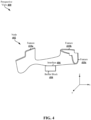
- FIG. 4 illustrates a perspective view 400 of a node 402 having a plurality of features 410a-c and a buffer block 404.
- the node 402 is additively manufactured (e.g., using a 3-D printing apparatus, such as a PBF apparatus).
- the node 402 may be constructed from a plastic, metal, alloy, or any suitable material or combination thereof.
- the components of FIG. 4 are made transparent for clarity, although the components may or may not be partially or fully transparent in various applications.
- the node 402 may be additively manufactured on a build plate, which may be affixed to the node 402 when the node is removed from the 3-D printing apparatus. After removal from the 3-D printing apparatus, the build plate may be removed from the node 402.
- the node 402 may be printed with one or more support structures. These support structures may additionally be removed from the node 402, e.g., before, during, or after one or more assembly processes and/or post-processing operations on the features 410a-c.
- a buffer block 404 may be connected with the node 402.
- the connection with between the buffer block 404 and the node 402 may be a rigid connection (e.g., as opposed to a compliant connection).
- the buffer block 404 may be connected with the node at an interface 406.
- the interface 406 is a zero-point interface.
- the node 402 may be scanned or probed (e.g., with contact or non-contact metrology). The relationship of the buffer block 404 with respect to the node 402 may be determined by this metrology operation with the node 402.
- the node 402 may be printed with one or more identification features, which may be scanned or probed to determine a position of the node 402.
- the node 402 may be additively manufactured with excess material to account for the tolerance stack-up between the node 402 and the buffer block 404; the excess material may be machined off the node 402 to ensure that the node 402 is in tolerance (e.g., with other nodes).
- a position of the node 402 on a table should be known to a relatively high degree of accuracy (e.g., within microns).
- a robotic assembly (or other machine) may attached to the buffer block 404 an position the buffer block 404 and node 402 on a table (e.g., within a CNC machine).
- the buffer block 404 may then be scanned or probed (e.g., with contact or non-contact metrology) to determine a position of the buffer block 404 - this position of the buffer block 404 may serve as an origin, a reference coordinate system, or the like.
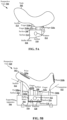
- FIGs. 5A-B perspective views 500, 520 illustrate a node 502 and a buffer block 504, with FIG. 5B including a supporting apparatus 506.
- the node 502 is additively manufactured (e.g., using a 3-D printing apparatus, such as a PBF apparatus).
- the node 502 may be constructed from a plastic, metal, alloy, or any suitable material or combination thereof.
- the components of FIG. 5 are made transparent for clarity, although the components may or may not be partially or fully transparent in various applications.
- the node 502, the buffer block 504, and/or the supporting apparatus 506 may be embodiments of other node(s), buffer block(s), and/or supporting apparatuses, respectively, described in the present disclosure.
- the plurality of fingers 510a may extend away from a first surface 508 of the buffer block 504.
- the plurality of fingers 510a-c may be configured to engage with one or more surfaces 514 of the node 502 to form the first rigid connection between the buffer block 504 and the node 502.
- the plurality of fingers 510a-c may be configured to clamp and/or grip the one or more surfaces 514 of the node 502.
- Features may be disposed on the one or more surfaces of the node for interfacing with the fingers.
- a second surface 516, different from the first surface 508, of the buffer block 504 may include at least one zero-point feature 512.
- the at least one zero-point feature 512 may be configured for a zero-point interface with a robotic assembly, automated constructor, and/or other machine, e.g., in order to position the node 502 for one or more assembly processes and/or post-processing operations.
- a supporting apparatus 506 is illustrated, in addition to the node 502 and the buffer block 504.
- the supporting apparatus 506 may be referred to as a block dock.
- the supporting apparatus 506 may be configured to be connected with a table (e.g., a table of a mill, a table of a CNC machine, etc.).
- the supporting apparatus 506 may include a first surface 524.
- the first surface 524 may bound a recess 526 formed in the supporting apparatus 506.
- the buffer block 504 may be at least partially disposed in the recess 526, with the first surface 508 of the buffer block 504 facing away from the recess 526 so that the plurality of fingers 510a-c may extend away from the recess 526 and engage with the one or more surfaces 514 of the node 502.
- At least a third surface 518 of the buffer block 504 may contact the first surface 524 of the supporting apparatus 506 within the recess 526.
- the third surface 518 of the buffer block 504 and the first surface 524 of the supporting apparatus 506 may be connected via at least one connection interface 528.
- the at least one connection interface 528 may form a rigid connection between the buffer block 504 and the supporting apparatus 506.
- the at least one connection interface 528 may include a zero-point interface.
- the buffer block 504 may include one or more zero-point features with which the supporting apparatus 506 is configured to engage to form the zero-point interface of the connection interface 528.
- the supporting apparatus 506 may include a plurality of pogo pins 530a-b.
- the plurality of pogo pins 530a-b may extend away from the first surface 524 of the supporting apparatus 506, e.g., at areas of the first surface 524 that are not forming the recess 526.
- a perspective view 600 illustrates a node 602 and a buffer block 604, and including a supporting apparatus 606.
- the node 602 is additively manufactured (e.g., using a 3-D printing apparatus, such as a PBF apparatus).
- the node 602 may be constructed from a plastic, metal, alloy, or any suitable material or combination thereof.
- the components of FIG. 6 are made transparent for clarity, although the components may or may not be partially or fully transparent in various applications.
- the node 602, the buffer block 604, and/or the supporting apparatus 606 may be embodiments of other node(s), buffer block(s), and/or supporting apparatuses, respectively, described in the present disclosure.
- the set of supporting features 630a-c may contact or connect with the one or more surfaces 614 of the node 602.
- the set of supporting features 630a-c may provide additional support for the node 602 during one or more assembly processes and/or post-processing operations.
- the set of supporting features 630a-c may prevent deflection of the node 602, particularly at relatively thin or weak portions of the node (e.g., proximate to at least one point of the node 602 that is to undergo assembly processes and/or post-processing operations).
- This set of supporting features 630a-c may provide sufficient support of the node 602 during the assembly processes and/or post-processing operations.
- At least one of the set of supporting features 630a-c may contact the node 602 at one or more points of the node 602 that are proximate to at least one point of the node 602 that is to undergo assembly processes and/or post-processing operations. Accordingly, the at least one of the set of features 630a-c may provide additional support and/or rigidity proximate to at least one point of the node 602 that is to undergo assembly processes and/or post-processing operations.
- the connection assembly 610 may form at least one zero-point interface with the node 602.
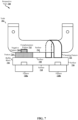
- the robotic assembly or other automated constructor may position the buffer block 704 so that the complementary portion 712 the complementary feature 710 is positioned within the negative feature 726 of the node 702 and thereby engage the negative feature 726 of the node 702.
- the engagement of the complementary feature 710 and the negative feature 726 may provide a zero-point interface between the buffer block 704 and the node 702.
- the buffer block 704 may be attached to the node 702 through one or more machining operations.
- the buffer block 704 may include a clamping feature 722.
- the clamping feature 722 may be a soft jaw.
- the clamping feature 722 may be specific to the node 702 Therefore, different clamping features may be used for different nodes.
- the clamping feature 722 may provide sufficient retention and clamping during one or more assembly processes and/or post-processing operations. Further, the clamping feature 722 may be removed after one or more assembly processes and/or post-processing operations.
- FIGs. 8A-C show perspective views 800, 820, 840 of a buffer block 804.
- the buffer block 804 may be configured to connect with a node 802, as illustrated with respect to FIG. 8B .
- the node 802 is additively manufactured (e.g., using a 3-D printing apparatus, such as a PBF apparatus).
- the node 802 may be additively manufacture for assembly.
- the node 802 may be constructed from a plastic, metal, alloy, or any suitable material or combination thereof.
- the components of FIG. 8 are made transparent for clarity, although the components may or may not be partially or fully transparent in various applications.
- the node 802 and/or the buffer block 804 may be embodiments of other node(s) and/or buffer block(s), respectively, described in the present disclosure.
- a supporting apparatus may be additionally included, as described in the present disclosure.
- the buffer block 804 may be configured with one at least one feature 828 to be engaged by a robotic assembly or other automated constructor.
- the at least one feature 828 may be disposed on a second surface 816 of the buffer block 804 that is different from a first surface 808.
- the buffer block 804 may have a plurality of features, including the at least one feature 828, disposed thereon in order to connect with a plurality of different robotic assemblies and/or other automated constructors.
- Each of the plurality of features, including the at least one feature 828 may enable a different robotic assembly and/or other automated constructor to engage with the buffer block 804 to move the buffer block (and node, when attached thereto) throughout various assembly processes and/or post-processing operations.
- the at least one feature 828 may be configured as zero-point features for a zero-point interface with the robotic assembly or other automated constructor.
- the interface apparatus 810 may be programmable.
- interface apparatus 810 may be configured to receive a command issued by a robotic assembly and/or other automated constructor.
- the buffer block 804 may receive the command and provide the command to the interface apparatus 810.
- one or more of the fingers 830a-c may be accordingly actuated.
- a command may cause one or more of the fingers 830a-c to be locked in place, which may be spring-assisted to maintain the locked position.
- commands may be provided by means of computer code that translates to actuation of one or more of the fingers 830a-c.
- the plurality of fingers 830a-c may be spring-assisted.
- the plurality of fingers 830a-c may be pneumatically actuated, and then spring-assisted to remain fully open (e.g., as illustrated in FIG. 8A ) and/or spring-assisted to remain fully closed (e.g., as illustrated in FIG. 8B ).
- the plurality of fingers 830a-c may radially move. In other embodiments, however, the plurality of fingers 830a-c may be configured to rotationally and/or telescopically move. The movement of the fingers 830a-c may be controlled via one or more commands issued by means of a robotic assembly and/or other automated constructor, and provided to the plurality of fingers 830a-c through the buffer block 804.
- the plurality of fingers 830a'-c' may be actuated to be in a fully closed position.
- the plurality of fingers 830a-c may be actuated to move from the fully open position to the fully closed position of the plurality of fingers 830a'-c'.
- the plurality of fingers 830a-c may be independently actuated to any position inclusively between the fully open position of the fingers 830a-c and the fully closed position of the fingers 830a'-c'.
- each of the plurality of fingers 830a-c may be independently actuated, e.g., so that each of the fingers 830a-c is able to be in a respective position that does not necessarily correspond with each of the other fingers 830a-c (e.g., one finger 830a may be in a fully open position while another finger 830b may be in a fully closed position).
- each of the fingers 830a-c may be actuated to a respective angle, and each of the fingers 830a-c may not be equidistantly actuated.
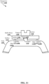
- the first surface 908 of the buffer block 904 may be connected with the node 902 through the build plate 906.
- the build plate 906 may include a portion 912 that is proximate to the center of the build plate and separated into sections (e.g., an array of build plates), as described with respect to FIG. 9A .
- Each section of the portion 912 of the build plate 906 may include a first surface 934 that faces away from the buffer block 904.
- Each first surface 934 may have extending therefrom a respective support feature 930a-c.
- the support features 930a-c may be printed on the portion 912 of the build plate 906, e.g., contemporaneously with the printing of the node 902.
- each support feature 930a-c may connect with the node 902.
- the support features 930a-c may connect with at least one surface 914 of the node 902 in order to form the rigid connection between the buffer block 904 and the node 902.
- the support features 930a-c may support thermal management, e.g., when the node 902 is machined by a mill 936.
- the one or more additional support features 924 may be absent, and only support features 930a-c extending from the proximally center portion 912 of the build plate 906 may contact the node 902. That is, the build plate 906 may be unconnected with the node 902 from a portion of the build plate 906 that surrounds the proximally center portion 912. However, the support features 930a-c may still provide a rigid connection between the buffer block 904 and the node 902.
- the buffer block 1204 may be configured with one at least one feature 1228 to be engaged by a robotic assembly or other automated constructor.
- the at least one feature 1228 may be disposed on a second surface 1216 of the buffer block 1204 that is different from a first surface 1208.
- the buffer block 1204 may have a plurality of features, including the at least one feature 1228, disposed thereon in order to connect with a plurality of different robotic assemblies and/or other automated constructors.
- Each of the plurality of features, including the at least one feature 1228 may enable a different robotic assembly and/or other automated constructor to engage with the buffer block 1204 to move the buffer block (and node, when attached thereto) throughout various assembly processes and/or post-processing operations.
- the at least one feature 1228 may be configured as zero-point features for a zero-point interface with the robotic assembly or other automated constructor.
- the compliance pedestal 1506 may include a second surface 1524.
- the second surface 1524 may face away from the first surface 1522 (e.g., the second surface 1524 may be disposed on an opposite side of the first surface 1522).
- the second surface 1524 of the supporting apparatus 1504 may be connected with a first surface 1526 of a compliance unit 1508.
- the first finger 1514 When at least a portion of the node 1502 disposed between the first finger 1514 and the second finger 1516, the first finger 1514 may be actuated. For example, the first finger 1514 may be actuated to move along an elevational plane toward the second finger 1516. The first finger 1514 may be actuated to move to contact at least a first surface 1542 of the node 1502.
Landscapes
- Engineering & Computer Science (AREA)
- Mechanical Engineering (AREA)
- Robotics (AREA)
- Chemical & Material Sciences (AREA)
- Manufacturing & Machinery (AREA)
- Materials Engineering (AREA)
- Combustion & Propulsion (AREA)
- Transportation (AREA)
- Powder Metallurgy (AREA)
Description
- The present disclosure relates to transport structures such as automobiles, trucks, trains, boats, aircraft, motorcycles, metro systems, and the like, and more specifically to techniques for securing nodes for various processes.
- A transport structure such as an automobile, truck or aircraft employs a large number of interior and exterior nodes. These nodes provide structure to the automobile, truck and aircraft, and respond appropriately to the many different types of forces that are generated or that result from various actions like accelerating and braking. These nodes also provide support. Nodes of varying sizes and geometries may be integrated in a transport structure, for example, to provide an interface between panels, extrusions, and/or other structures. Thus, nodes are an integral part of transport structures.
- Most nodes must be coupled to, or interface securely with, another part or structure in secure, well-designed ways. In order to securely connect a node with another part or structure, the node may need to undergo one or more processes in order to prepare the node to connect with the other part or structure. For example, the node may be machined at an interface in order to connect with various other parts or structures. Further examples of processes include surface preparation operations, heat treatment, electrocoating, electroplating, anodization, chemical etching, cleaning, support removal, powder removal, and so forth.
- In order to perform the various processes on the node, the node may be securely fixed in a position, e.g., so that a mill may machine the interface of the node at a precise location. When the node is unsecured and/or the position of the node is inaccurate during one or more of the aforementioned processes, the node may be erroneously and irreparably altered (e.g., through machining). Further, because a number of different processes may be performed on the node, the position of the node should be reproducibly obtainable. Thus, a need exists for an approach to consistently positioning a node with a high degree of precision before, during, and/or after performing various processes on the node.
-
US 2004/056405 A1 relates to a tooling plate to fixture a workpiece for a vehicle subassembly, including a planar body for supporting fixture tools for holding a workpiece, a connector mechanism to allow the planar body to be removably connected with a workpiece presenter, and a locater mechanism to locate the planar body with respect to the workpiece presenter in a repeatable manner. -
CN 108 115 253 A relates to a manufacture system of steel structural joint. The system comprises a terminal, a control mechanism, a digital welder, a robot, a coordinating mechanism and a wire feeding mechanism. -
EP 2 724 813 A1 -
EP 2 778 992 A1 relates to a computing device including a processor, operative on a plurality of constraints associated with a component, and integrates the constraints with a design optimization methodology across multiple variables including additive manufacturing constraints to generate a specification for the component. - The present invention provides a buffer block apparatus for securing a node with the features of
claim 1 and a method of securing a node for machining with the features of claim 13. - The present disclosure generally relates to additively manufactured nodes in an environment (e.g., a production environment) for various operations (e.g., machining and assembly). Because additively manufactured nodes may appreciably vary in geometry, a repeatable approach to attachment and detachment with the node for the various operations may improve securing different nodes for the various operations. Such an approach may include a reusable apparatus or assembly that may not necessarily be incorporated into (e.g., additively manufactured with) the node.
- An example of such an apparatus may be a buffer block. A buffer block many enable a plurality of additively manufactured nodes with different geometries to be picked up and utilized in assembly processes and/or post-processing operations. The coordinate axis of the buffer block may be constant and, therefore, the buffer block may serve as a reference point (e.g., reference coordinate system) for a plurality of nodes undergoing various operations. In so doing, the buffer block may reduce or eliminate the need for custom fixturing that is dependent on the geometry of the node (e.g., custom features that are additively manufactured on the node for scanning or probing the node before machining).
- It will be understood that other aspects of mechanisms for realizing adhesive connections with additively manufactured components and the manufacture thereof will become readily apparent to those skilled in the art from the following detailed description, wherein it is shown and described only several embodiments by way of illustration. As will be realized by those skilled in the art, the disclosed subject matter is capable of other and different embodiments and its several details are capable of modification in various other respects, all without departing from the invention. Accordingly, the drawings and detailed description are to be regarded as illustrative in nature and not as restrictive.
-
-
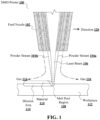
FIG. 1 illustrates an exemplary embodiment of certain aspects of a Direct Metal Deposition (DMD) 3-D printer. -
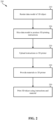
FIG. 2 illustrates a conceptual flow diagram of a 3-D printing process using a 3-D printer. -
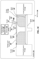
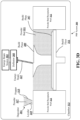
FIGs. 3A-D illustrate exemplary powder bed fusion (PBF) systems during different stages of operation. -
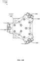
FIG. 4 illustrates a perspective of a node. -
FIGs. 5A-B illustrate a node in connection with a buffer block. -
FIG. 6 illustrates a node in connection with a buffer block. -
FIG. 7 illustrates a node in connection with a buffer block. -
FIGs. 8A-C illustrate a node in connection with a buffer block. -
FIGs. 9A-B illustrate a node in connection with a buffer block. -
FIG. 10 illustrates a node in connection with a buffer block. -
FIG. 11 illustrates a node in connection with a buffer block. -
FIG. 12 illustrates a node in connection with a buffer block. -
FIG. 13 illustrates a node in connection with a buffer block. -
FIGs. 14A-C illustrates a buffer block and connection assembly. -
FIG. 15 illustrates a node in connection with a supporting apparatus. -
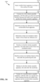
FIG. 16 is a flow diagram of an exemplary method of supporting a node. -
FIG. 17 illustrates a node in connection with a buffer block. -
FIG. 18 illustrates a supporting apparatus supporting a node connected with a buffer block. - The detailed description set forth below in connection with the appended drawings is intended to provide a description of various exemplary embodiments and is not intended to represent the only embodiments in which the invention may be practiced. The term "exemplary" used throughout this disclosure means "serving as an example, instance, or illustration," and should not necessarily be construed as preferred or advantageous over other embodiments presented in this disclosure. The detailed description includes specific details for the purpose of providing a thorough and complete disclosure that fully conveys the scope of the invention to those skilled in the art. However, the invention may be practiced without these specific details. In some instances, well-known structures and components may be shown in block diagram form, or omitted entirely, in order to avoid obscuring the various concepts presented throughout this disclosure. In addition, the figures may not be drawn to scale and instead may be drawn in a way that attempts to most effectively highlight various features relevant to the subject matter described.
- Additive Manufacturing (3-D Printing). Additive manufacturing (AM) is advantageously a non-design specific manufacturing technique. AM provides the ability to create complex structures within a part. For example, nodes can be produced using AM. A node is a structural member that may include one or more interfaces used to connect to other spanning components such as tubes, extrusions, panels, other nodes, and the like. Using AM, a node may be constructed to include additional features and functions, depending on the objectives. For example, a node may be printed with one or more ports that enable the node to secure two parts by injecting an adhesive rather than welding multiple parts together, as is traditionally done in manufacturing complex products. Alternatively, some components may be connected using a brazing slurry, a thermoplastic, a thermoset, or another connection feature, any of which can be used interchangeably in place of an adhesive. Thus, while welding techniques may be suitable with respect to certain embodiments, additive manufacturing provides significant flexibility in enabling the use of alternative or additional connection techniques.
- A variety of different AM techniques have been used to 3-D print components composed of various types of materials. Numerous available techniques exist, and more are being developed. For example, Directed Energy Deposition (DED) AM systems use directed energy sourced from laser or electron beams to melt metal. These systems utilize both powder and wire feeds. The wire feed systems advantageously have higher deposition rates than other prominent AM techniques. Single Pass Jetting (SPJ) combines two powder spreaders and a single print unit to spread metal powder and to print a structure in a single pass with apparently no wasted motion. As another illustration, electron beam additive manufacturing processes use an electron beam to deposit metal via wire feedstock or sintering on a powder bed in a vacuum chamber. Single Pass Jetting is another exemplary technology claimed by its developers to be much quicker than conventional laser-based systems. Atomic Diffusion Additive Manufacturing (ADAM) is still another recently developed technology in which components are printed, layer-by-layer, using a metal powder in a plastic binder. After printing, plastic binders are removed and the entire part is sintered at once into a desired metal.
- One of several such AM techniques, as noted, is DMD.
FIG. 1 illustrates an exemplary embodiment of certain aspects of a DMD 3-D printer 100.DMD printer 100 uses feednozzle 102 moving in apredefined direction 120 to propelpowder streams laser beam 106, which is directed toward aworkpiece 112 that may be supported by a substrate. Feed nozzle may also include mechanisms for streaming ashield gas 116 to protect the welded area from oxygen, water vapor, or other components. - The powdered metal is then fused by the
laser 106 in amelt pool region 108, which may then bond to theworkpiece 112 as a region of depositedmaterial 110. Thedilution area 114 may include a region of the workpiece where the deposited powder is integrated with the local material of the workpiece. Thefeed nozzle 102 may be supported by a computer numerical controlled (CNC) robot or a gantry, or other computer-controlled mechanism. Thefeed nozzle 102 may be moved under computer control multiple times along a predetermined direction of the substrate until an initial layer of the depositedmaterial 110 is formed over a desired area of theworkpiece 112. Thefeed nozzle 102 can then scan the region immediately above the prior layer to deposit successive layers until the desired structure is formed. In general, thefeed nozzle 102 may be configured to move with respect to all three axes, and in some instances to rotate on its own axis by a predetermined amount. -
FIG. 2 is a flow diagram 200 illustrating an exemplary process of 3-D printing. A data model of the desired 3-D object to be printed is rendered (operation 210). A data model is a virtual design of the 3-D object. Thus, the data model may reflect the geometrical and structural features of the 3-D object, as well as its material composition. The data model may be created using a variety of methods, including CAE-based optimization, 3D modeling, photogrammetry software, and camera imaging. CAE-based optimization may include, for example, cloud-based optimization, fatigue analysis, linear or non-linear finite element analysis (FEA), and durability analysis. - 3-D modeling software, in turn, may include one of numerous commercially available 3-D modeling software applications. Data models may be rendered using a suitable computer-aided design (CAD) package, for example in an STL format. STL is one example of a file format associated with commercially available stereolithography-based CAD software. A CAD program may be used to create the data model of the 3-D object as an STL file. Thereupon, the STL file may undergo a process whereby errors in the file are identified and resolved.
- Following error resolution, the data model can be "sliced" by a software application known as a slicer to thereby produce a set of instructions for 3-D printing the object, with the instructions being compatible and associated with the particular 3-D printing technology to be utilized (operation 220). Numerous slicer programs are commercially available. Generally, the slicer program converts the data model into a series of individual layers representing thin slices (e.g., 100 microns thick) of the object be printed, along with a file containing the printer-specific instructions for 3-D printing these successive individual layers to produce an actual 3-D printed representation of the data model.
- The layers associated with 3-D printers and related print instructions need not be planar or identical in thickness. For example, in some embodiments depending on factors like the technical sophistication of the 3-D printing equipment and the specific manufacturing objectives, etc., the layers in a 3-D printed structure may be non-planar and/or may vary in one or more instances with respect to their individual thicknesses.
- A common type of file used for slicing data models into layers is a G-code file, which is a numerical control programming language that includes instructions for 3-D printing the object. The G-code file, or other file constituting the instructions, is uploaded to the 3-D printer (operation 230). Because the file containing these instructions is typically configured to be operable with a specific 3-D printing process, it will be appreciated that many formats of the instruction file are possible depending on the 3-D printing technology used.
- In addition to the printing instructions that dictate what and how an object is to be rendered, the appropriate physical materials necessary for use by the 3-D printer in rendering the object are loaded into the 3-D printer using any of several conventional and often printer-specific methods (operation 240). In DMD techniques, for example, one or more metal powders may be selected for layering structures with such metals or metal alloys. In selective laser melting (SLM), selective laser sintering (SLS), and other PBF-based AM methods (see below), the materials may be loaded as powders into chambers that feed the powders to a build platform. Depending on the 3-D printer, other techniques for loading printing materials may be used.
- The respective data slices of the 3-D object are then printed based on the provided instructions using the material(s) (operation 250). In 3-D printers that use laser sintering, a laser scans a powder bed and melts the powder together where structure is desired, and avoids scanning areas where the sliced data indicates that nothing is to be printed. This process may be repeated thousands of times until the desired structure is formed, after which the printed part is removed from a fabricator. In fused deposition modelling, as described above, parts are printed by applying successive layers of model and support materials to a substrate. In general, any suitable 3-D printing technology may be employed for purposes of this disclosure.
- Another AM technique includes powder-bed fusion ("PBF"). Like DMD, PBF creates `build pieces' layer-by-layer. Each layer or 'slice' is formed by depositing a layer of powder and exposing portions of the powder to an energy beam. The energy beam is applied to melt areas of the powder layer that coincide with the cross-section of the build piece in the layer. The melted powder cools and fuses to form a slice of the build piece. The process can be repeated to form the next slice of the build piece, and so on. Each layer is deposited on top of the previous layer. The resulting structure is a build piece assembled slice-by-slice from the ground up.
-
FIGS. 3A-D illustrate respective side views of anexemplary PBF system 300 during different stages of operation. As noted above, the particular embodiment illustrated inFIGS. 3A-D is one of many suitable examples of a PBF system employing principles of this disclosure. It should also be noted that elements ofFIGS. 3A-D and the other figures in this disclosure are not necessarily drawn to scale, but may be drawn larger or smaller for the purpose of better illustration of concepts described herein.PBF system 300 can include adepositor 301 that can deposit each layer of metal powder, anenergy beam source 303 that can generate an energy beam, adeflector 305 that can apply the energy beam to fuse the powder, and abuild plate 307 that can support one or more build pieces, such as abuild piece 309.PBF system 300 can also include abuild floor 311 positioned within a powder bed receptacle. The walls of thepowder bed receptacle 312 generally define the boundaries of the powder bed receptacle, which is sandwiched between thewalls 312 from the side and abuts a portion of thebuild floor 311 below.Build floor 311 can progressivelylower build plate 307 so thatdepositor 301 can deposit a next layer. The entire mechanism may reside in achamber 313 that can enclose the other components, thereby protecting the equipment, enabling atmospheric and temperature regulation and mitigating contamination risks.Depositor 301 can include ahopper 315 that contains apowder 317, such as a metal powder, and aleveler 319 that can level the top of each layer of deposited powder. - Referring specifically to
FIG. 3A , this figure showsPBF system 300 after a slice ofbuild piece 309 has been fused, but before the next layer of powder has been deposited. In fact,FIG. 3A illustrates a time at whichPBF system 300 has already deposited and fused slices in multiple layers, e.g., 150 layers, to form the current state ofbuild piece 309, e.g., formed of 150 slices. The multiple layers already deposited have created apowder bed 321, which includes powder that was deposited but not fused. - FIG. 3B shows
PBF system 300 at a stage in which buildfloor 311 can lower by apowder layer thickness 323. The lowering ofbuild floor 311 causesbuild piece 309 andpowder bed 321 to drop bypowder layer thickness 323, so that the top of the build piece and powder bed are lower than the top of powderbed receptacle wall 312 by an amount equal to the powder layer thickness. In this way, for example, a space with a consistent thickness equal topowder layer thickness 323 can be created over the tops ofbuild piece 309 andpowder bed 321. -
FIG. 3C showsPBF system 300 at a stage in whichdepositor 301 is positioned to depositpowder 317 in a space created over the top surfaces ofbuild piece 309 andpowder bed 321 and bounded by powderbed receptacle walls 312. In this example,depositor 301 progressively moves over the defined space while releasingpowder 317 fromhopper 315.Leveler 319 can level the released powder to form apowder layer 325 that has a thickness substantially equal to the powder layer thickness 323 (see FIG. 3B). Thus, the powder in a PBF system can be supported by a powder support structure, which can include, for example, abuild plate 307, abuild floor 311, abuild piece 309,walls 312, and the like. It should be noted that the illustrated thickness of powder layer 325 (i.e., powder layer thickness 323 (FIG. 3B)) is greater than an actual thickness used for the example involving 350 previously-deposited layers discussed above with reference toFIG. 3A . -
FIG. 3D showsPBF system 300 at a stage in which, following the deposition of powder layer 325 (FIG. 3C ),energy beam source 303 generates anenergy beam 327 anddeflector 305 applies the energy beam to fuse the next slice inbuild piece 309. In various exemplary embodiments,energy beam source 303 can be an electron beam source, in whichcase energy beam 327 constitutes an electron beam.Deflector 305 can include deflection plates that can generate an electric field or a magnetic field that selectively deflects the electron beam to cause the electron beam to scan across areas designated to be fused. In various embodiments,energy beam source 303 can be a laser, in whichcase energy beam 327 is a laser beam.Deflector 305 can include an optical system that uses reflection and/or refraction to manipulate the laser beam to scan selected areas to be fused. - In various embodiments, the
deflector 305 can include one or more gimbals and actuators that can rotate and/or translate the energy beam source to position the energy beam. In various embodiments,energy beam source 303 and/ordeflector 305 can modulate the energy beam, e.g., turn the energy beam on and off as the deflector scans so that the energy beam is applied only in the appropriate areas of the powder layer. For example, in various embodiments, the energy beam can be modulated by a digital signal processor (DSP). - This disclosure presents a technique for securing a node to perform one or more assembly processes and/or post-processing operations. Examples of assembly processes and/or post-processing operations include machining, surface preparation operations, heat treatment, electrocoating, electroplating, anodization, chemical etching, part cleaning, support removal, powder removal, and other operations. To better facilitate assembly, the node may be printed in two or more parts, with the two or more parts being fastened mechanically prior to sealing and/or injection. In an exemplary embodiment, the node may constitute a base structure with sides protruding from the base structure to define a recess for accepting a structure. In other embodiments, the node may constitute additional features, such as connection features to other structures or other structural or functional features that are not explicitly shown in the illustrations herein to avoid unduly obscuring the concepts of the disclosure and to focus on the node-structure interface aspect of the node. These additional features of the node may cause portions of the node to take a different shape or may add structures and geometrical features that are not present in the illustrations herein. These additional features and structures may be additively manufactured along with the remainder of the node, although this may not necessarily be the case, as in some applications, traditional manufacturing techniques such as casting or machining may be used.
- In various embodiments, a buffer block may be used to interface with a node. For example, the buffer block may provide an approach to connecting with a node by a robotic assembly and/or other automated constructor during various operations of the assembly processes and/or post-processing operations. The buffer block may provide a repeatable approach to connecting with (e.g., picking up) one or more additively manufactured nodes, such as different nodes of different geometries.
- Further, the buffer block may provide a repeatable approach to connecting with (e.g., picking up) the same node at different times during the assembly processes and/or post-processing operations (e.g., during machining, during electrocoating, etc.). In particular, the buffer block may facilitate handoff of the node between different robotic assemblies and/or other machines. That is, the buffer block may enable a plurality of nodes to be held in an assembly environment, and the buffer block may reduce or eliminate the need for node-specific fixturing. For example, with a buffer block described in the present disclosure, the need for printing and/or installing custom fixtures on each node may be reduced or eliminated by the universality of the buffer block. In another example, the need for node-specific tooling and/or effectors may be reduced and/or eliminated. As described in the present disclosure, a buffer block may be implemented in a variety of embodiments.
- A buffer block may include at least one feature that is configured to interface with tool changers, effectors, or other mechanisms of a robotic assembly and/or other automated constructor. Such features may be disposed on different surfaces of the buffer block. Further, the buffer block may include a plurality of interfaces, each of which may be configured to interface with a plurality of tools implemented by a robotic assembly and/or other automated constructor. Thus, the buffer block may enable a node to traverse assembly processes and/or post-processing operations in which different tools are utilized by different robotic assemblies and/or automated constructors.
- In one aspect, the buffer block may be configured for a zero-point interface with a robotic assembly and/or other automated constructor, e.g., so that the robotic assembly and/or other automated constructor may connect with the buffer block and node before, during, and/or after assembly processes, post-processing operations, and/or installation of the node into the transport structure (e.g., chassis). A robotic assembly and/or other automated constructor may move and position a node and buffer block assembly before, during, and/or after assembly processes, post-processing operations, and/or installation of the node into the transport structure.
- The connection between the buffer block and the robotic assembly or other automated constructor may be a rigid connection (e.g., as opposed to a compliant connection). A rigid connection may include a connection through which the node is prevented from rotation and translation in each of six degrees of freedom - e.g., any rotation or translation of the node relative to the buffer block may not exceed a threshold amount of microns, for example, that may be less than one millimeter or one tenth of a millimeter.
- An interface may be highly accurate and repeatable, for example, in connection with one or more features that are highly accurate and repeatable. In an aspect, a highly accurate and repeatable interface may be a zero-point interface, which may provide a rigid connection that prevents rotation and translation of the buffer block in each of six degrees of freedom. A zero-point interface may be enabled through one or more highly accurate and repeatable features (e.g., zero-point features), which may be included on and/or installed on the buffer block.
- An example of a zero-point interface includes a 3-2-1 locking mechanism, in which a first zero-point feature enables locking three degrees of freedom, a second zero-point feature enables locking two degrees of freedom, and a third zero-point feature enables locking one degree of freedom. Thus, each of six degrees of freedom may be locked, e.g., when a robotic assembly and/or other automated constructor engages with each of the first, second, and third zero-point features (e.g., male features of the robotic assembly and/or other automated constructor may "mate" with female zero-point features of the buffer block).
- A zero-point interface may not over-constrain rotation and/or translation of the buffer block relative to a robotic assembly and/or other automated constructor. In particular, two zero-point features of the buffer block may not be used to constrain the same degree of freedom. For example, each zero-point feature of the buffer block may constrain the buffer block on at least one plane and, therefore, each zero-point feature may constrain rotation or translation of the buffer block in at least one plane that is different from each of the other planes constrained by another zero-point feature.
- A buffer block may connect with a node at a first surface of the buffer block that is different from the one or more surfaces at which the buffer block interfaces with a robotic assembly and/or other automated constructor. At the first surface of the buffer block, the buffer block may be directly connected with node and/or the buffer block may connect with the node through one or more interface apparatuses, such as an interface plate, a clamp, a grabber, and/or another technique described herein. In some embodiments, an interface apparatus may be a custom manufactured assembly.
- An interface apparatus may be configured to engage with the node to pick up the node, maintain the connection with the node, and release the node as needed. Pursuant thereto, a buffer block may include one or more channels, valves, and the like that allow for an injectable substance (e.g., air, hydraulic fluid, etc.) to be routed to an interface apparatus so that the interface apparatus may be actuated (e.g., as finger grabbers, clamps, and so forth are to be actuated). Alternatively or additionally, an interface apparatus may be actuated and/or maintained in an engaged configuration through one or more springs.
- In some embodiments, a robotic assembly, automated constructor, and/or other machine may provide commands that cause introduction of an injectable substance and actuation of an interface apparatus. In one example, a robotic assembly connected with the buffer block may approach a node with a gripper positioned toward the node in a retracted position and, once the gripper contacts the node, the robotic assembly may issue a command to actuate (e.g., extend) the gripper and secure (e.g., grab) the node.
- In some embodiments, the node may include (e.g., may be printed with) one or more features and/or surfaces that provide sufficient grip or traction to enable the connection with the buffer block. Examples of sufficient grip or traction may include texturing of one or more surfaces or the node, female receiver features included on the node, tabs included on the node, or another feature that ensures the connection with the buffer block is preserved. For example, the node may be printed with three features to interface with a three-finger gripper. In one example, the one or more features of the node may be printed or included on a same plane. Depending on the geometry of the node, some features of the node may be printed on bosses. By printing features of the node on bosses, a gripper (e.g., 3-finger gripper) may connect the buffer block with the node.
- In aspects, the buffer block may connect with a node to form a rigid connection. The rigid connection may prevent the node from rotational and/or translational movement, e.g., at a micron level. A rigid connection between the node and the buffer block may prevent any rotation and translation of the node in all six degrees of freedom relative to the buffer block. For example, a rigid connection may constrain rotation and translation of the node relative to the buffer block to be within a threshold amount of microns, e.g., that may be less than one millimeter or one tenth of a millimeter.
- In some embodiments, a zero-point interface may provide the rigid connection that prevents rotation and translation of the node relative to the buffer block in each of six degrees of freedom. A zero-point interface may be enabled through one or more zero-point features, which may be included on (e.g., printed on) and/or installed on the node and/or the buffer block. An example of a zero-point interface includes a 3-2-1 locking mechanism. For example, male features of the buffer block may "mate" with female zero-point features of the node. In addition, the zero-point interface may not over-constrain rotation and/or translation of the node relative to the buffer block (e.g., each zero-point feature may constrain rotation or translation of the node in at least one plane that is different from each of the other planes constrained by another zero-point feature).
- The buffer block may convey reference information (e.g., an origin, a reference coordinate system, reference frame, etc.) to a robotic assembly, other automated constructor, and/or other machine (e.g., CNC machine) with respect to the node. Thus, the buffer block may be a precision-engineered apparatus. Such a robotic assembly, automated constructor, and/or other machine may use the reference frame provided by the buffer block before, during, and/or after manipulation of the node through assembly processes and/or post-processing operations. For example, a translation matrix may be generated based on the reference information in order to obtain the position of the node.
- The buffer block may be at least as robust as a node to which the buffer block is connected. That is, the buffer block may withstand different processes of the assembly processes and/or post-processing operations. For example, the buffer block may be configured to withstand one or more of machining, surface preparation, heat treatment, heat coating, electrocoating, electroplating, anodization, chemical etching, cleaning, etc. In aspects, the buffer block is able to form a rigid connection with the node during all of these assembly and/or post-processing operations.
- In some embodiments, the buffer block may be contemporaneously connected with both a robotic assembly or other automated constructor and the node (e.g., during machining or other assembly/post-processing operation). For example, a CNC mill may serve as a base for a robotic assembly and the buffer block (simultaneously connected with the robotic assembly and the node) may be connected with both the robotic assembly and the node. Accordingly, the robotic assembly may provide the requisite force(s) to prevent or minimize displacement of the node during machining or other assembly/post-processing operations.
- Further to the present disclosure, a node may be secured with a supporting apparatus, embodiments of which may or may not include a buffer block. The supporting apparatus may retain the node, e.g., during machining or other assembly/post-processing operations. Thus, the supporting apparatus may prevent or minimize displacement and/or deflection of the node during such operations.
- In some embodiments, the supporting apparatus may be referred to as a block dock, such as when the buffer block is present in certain embodiments that include the supporting apparatus. The supporting apparatus may provide an interface to the buffer block and form a rigid connection.
- According to some embodiments, the supporting apparatus may include a compliance unit to which a clamping system is affixed. The clamping system may include a fixed arm and an actuated arm. In one example, a robotic assembly may move a node connected with a buffer block to the supporting apparatus, e.g., so that a portion of the node contacts the fixed arm. Once the fixed arm interfaces with the node and buffer block assembly (e.g., at a portion of the node), the actuated arm may be actuated to clamp the node in position. The compliance unit of the supporting apparatus may prevent movement (e.g., deflection, displacement, etc.) of the node while the clamping action is performed. That is, the compliance unit may allow the supporting apparatus to move in one or more of six degrees of freedom (e.g., three rotational degrees of freedom).
- In another embodiment, the clamping system may provide compliance in one or more of six degrees of freedom (e.g., three rotational degrees of freedom). In such an embodiment, the compliance unit may enable the supporting apparatus to be free-floating when the clamping action is performed, but may become fixed when the clamping action is complete. That is, once clamping is achieved, the compliance unit may become rigid. Additionally, the node, buffer block, and/or robotic assembly (or other automated constructor) may also be rigidly connected.
- After the rigid connection(s) are achieved, various assembly and/or post-processing operations may be performed. The node may be repositioned (e.g., reoriented) as needed to enable access to other features (e.g., joints, through holes, tabs, slabs, etc.) that are to undergo other assembly/post-processing operations.
- Further, the supporting apparatus may be connected with the node, e.g., near regions of the node that are machined so that those regions are supported during various assembly processes (e.g., machining, etc.) and/or post-processing operations. The connection with the node may be rigid, compliant, or a combination - e.g., the connection with the node may begin as compliant, and later become rigid. For example, a compliant connection with the node may be beneficial to prevent deflection of the relative fine interfaces of the node during machining.
- In some embodiments, the node may include one or more supporting features, which may be configured to interface with the supporting apparatus. Such supporting features may be co-printed (e.g., additively manufactured) with the node and/or may be installed on the node after printing. An example of a supporting feature may include an interface for a spherical support interface whereby the supporting apparatus connects with the node.
- As described in the present disclosure, the supporting apparatus may be unconnected with the buffer block. According to some embodiments, the support apparatus may connect with the node at a zero-point interface, e.g., at a zero-point feature that is included on the node. A robotic assembly, automated constructor, and/or other machine may connect with the node at another zero-point interface. The buffer block may be absent. In another embodiment, a node may be connected with a buffer block at first (e.g., to position the node on a table) and, after the node is positioned and secured with a supporting apparatus, the buffer block may be removed or the robotic assembly may be detached from the buffer block.
- The present disclosure provides various different embodiments of supporting and/or securing nodes for assembly processes and/or post-processing operations. It will be appreciated that various embodiments described herein may be practiced together. For example, an embodiment described with respect to one illustration of the present disclosure may be implemented in another embodiment described with respect to another illustration of the present disclosure.
-
FIG. 4 illustrates aperspective view 400 of anode 402 having a plurality offeatures 410a-c and abuffer block 404. In an exemplary embodiment, thenode 402 is additively manufactured (e.g., using a 3-D printing apparatus, such as a PBF apparatus). Thenode 402 may be constructed from a plastic, metal, alloy, or any suitable material or combination thereof. The components ofFIG. 4 are made transparent for clarity, although the components may or may not be partially or fully transparent in various applications. - The
node 402 may be additively manufactured on a build plate, which may be affixed to thenode 402 when the node is removed from the 3-D printing apparatus. After removal from the 3-D printing apparatus, the build plate may be removed from thenode 402. - The
node 402 may be printed with one or more support structures. These support structures may additionally be removed from thenode 402, e.g., before, during, or after one or more assembly processes and/or post-processing operations on thefeatures 410a-c. - A
buffer block 404 may be connected with thenode 402. The connection with between thebuffer block 404 and thenode 402 may be a rigid connection (e.g., as opposed to a compliant connection). Thebuffer block 404 may be connected with the node at aninterface 406. In one embodiment, theinterface 406 is a zero-point interface. - In one embodiment, the
buffer block 404 may be connected to thenode 402 with a gripper, jaw, clamp, or other connection mechanism, which may interface with thenode 402 and fully constrain thenode 402 relative to the buffer block 404 (e.g., to form a rigid connection). In one embodiment, thebuffer block 404 may be connected with thenode 402 via an interface plate at theinterface 406. Such embodiments may be described in more detail, infra. - After the buffer block is scanned or probed, the
node 402 may be scanned or probed (e.g., with contact or non-contact metrology). The relationship of thebuffer block 404 with respect to thenode 402 may be determined by this metrology operation with thenode 402. In an embodiment, thenode 402 may be printed with one or more identification features, which may be scanned or probed to determine a position of thenode 402. In an embodiment, thenode 402 may be additively manufactured with excess material to account for the tolerance stack-up between thenode 402 and thebuffer block 404; the excess material may be machined off thenode 402 to ensure that thenode 402 is in tolerance (e.g., with other nodes). - Transport structures may include a variety of different nodes, which may need to be machined or otherwise processed. Such processing may occur at features of a node, the locations of which may vary across different nodes. Accordingly, a flexible system to facilitate the accurate repeatability of assembly processes and/or post-processing operations across different nodes is needed, and may be provided by a
buffer block 404. - The
node 402 may include a plurality offeatures 410a-c. The plurality offeatures 410a-c may include portions or sections of thenode 402 that are to undergo one or more assembly processes and/or post-processing operations (e.g., machining, cleaning, heat treatment, etc.). Examples of thefeatures 410a-c include interfaces, joints, holes (e.g., rivet holes), slabs, bearing boards, and so forth. Thesefeatures 410a-c may need to be precision engineered to be included in a transport structure. Accordingly, thefeatures 410a-c may undergo one or more of the assembly processes and/or post-processing operations described herein, such as machining, surface preparation, heat treatment, electrocoating, electroplating, anodization, chemical etching, cleaning, support removal, powder removal, and/or other assembly processes and/or post-processing operations. Such assembly processes and/or post-processing operations may occur after thenode 402 is printed with 3-D printing operations (e.g., as described, supra, with respect to one or more ofFIGs. 1 ,2 , and/or 3A-D). - Because the
features 410a-c may be precision engineered, a position of thenode 402 on a table (e.g., mill table) should be known to a relatively high degree of accuracy (e.g., within microns). A robotic assembly (or other machine) may attached to the buffer block 404 an position thebuffer block 404 andnode 402 on a table (e.g., within a CNC machine). Thebuffer block 404 may then be scanned or probed (e.g., with contact or non-contact metrology) to determine a position of the buffer block 404 - this position of thebuffer block 404 may serve as an origin, a reference coordinate system, or the like. - With reference to
FIGs. 5A-B , perspective views 500, 520 illustrate anode 502 and abuffer block 504, withFIG. 5B including a supporting apparatus 506. In an exemplary embodiment, thenode 502 is additively manufactured (e.g., using a 3-D printing apparatus, such as a PBF apparatus). Thenode 502 may be constructed from a plastic, metal, alloy, or any suitable material or combination thereof. The components ofFIG. 5 are made transparent for clarity, although the components may or may not be partially or fully transparent in various applications. Thenode 502, thebuffer block 504, and/or the supporting apparatus 506 may be embodiments of other node(s), buffer block(s), and/or supporting apparatuses, respectively, described in the present disclosure. - In
FIG. 5A , thebuffer block 504 may be connected with thenode 502 to form a first rigid connection. The connection between thebuffer block 504 and thenode 502 may be a mechanical connection. Thebuffer block 504 may be connected with thenode 502 in order to move with the part through one or more of the assembly processes and/or post-processing processes. - The
buffer block 504 may be connected with thenode 502 by a plurality offingers 510a-c. For example, the plurality offingers 510a-c may be an interface apparatus disposed between thebuffer block 504 and thenode 502 in order to form the rigid connection between thebuffer block 504 and thenode 502. - The plurality of
fingers 510a may extend away from afirst surface 508 of thebuffer block 504. The plurality offingers 510a-c may be configured to engage with one ormore surfaces 514 of thenode 502 to form the first rigid connection between thebuffer block 504 and thenode 502. In one embodiment, the plurality offingers 510a-c may be configured to clamp and/or grip the one ormore surfaces 514 of thenode 502. Features may be disposed on the one or more surfaces of the node for interfacing with the fingers. - In various embodiments, a
second surface 516, different from thefirst surface 508, of thebuffer block 504 may include at least one zero-point feature 512. The at least one zero-point feature 512 may be configured for a zero-point interface with a robotic assembly, automated constructor, and/or other machine, e.g., in order to position thenode 502 for one or more assembly processes and/or post-processing operations. - With reference to
FIG. 5B , a supporting apparatus 506 is illustrated, in addition to thenode 502 and thebuffer block 504. In some embodiments, the supporting apparatus 506 may be referred to as a block dock. The supporting apparatus 506 may be configured to be connected with a table (e.g., a table of a mill, a table of a CNC machine, etc.). - The supporting apparatus 506 may include a
first surface 524. Thefirst surface 524 may bound arecess 526 formed in the supporting apparatus 506. Thebuffer block 504 may be at least partially disposed in therecess 526, with thefirst surface 508 of thebuffer block 504 facing away from therecess 526 so that the plurality offingers 510a-c may extend away from therecess 526 and engage with the one ormore surfaces 514 of thenode 502. - In some embodiments, at least a
third surface 518 of thebuffer block 504 may contact thefirst surface 524 of the supporting apparatus 506 within therecess 526. Thethird surface 518 of thebuffer block 504 and thefirst surface 524 of the supporting apparatus 506 may be connected via at least oneconnection interface 528. The at least oneconnection interface 528 may form a rigid connection between thebuffer block 504 and the supporting apparatus 506. - In one embodiment, the at least one
connection interface 528 may include a zero-point interface. For example, thebuffer block 504 may include one or more zero-point features with which the supporting apparatus 506 is configured to engage to form the zero-point interface of theconnection interface 528. - According to the illustrated embodiment, the supporting apparatus 506 may include a plurality of
pogo pins 530a-b. The plurality ofpogo pins 530a-b may extend away from thefirst surface 524 of the supporting apparatus 506, e.g., at areas of thefirst surface 524 that are not forming therecess 526. - The plurality of
pogo pins 530a-b may contact or connect with the one ormore surfaces 514 of thenode 502. For example, the plurality ofpogo pins 530a-b may provide additional support for thenode 502 during one or more assembly processes and/or post-processing operations. - The plurality of
pogo pins 530a-b may contact thenode 502 at one or more points of thenode 502 that are proximate to one or moreother points 532a-b of thenode 502 that are to undergo assembly processes and/or post-processing operations. Accordingly, the plurality ofpogo pins 530a-b may provide additional support and/or rigidity at thosepoints 532a-b of thenode 502 that are to undergo assembly processes and/or post-processing operations. - In some embodiments, the connection between the plurality of
pogo pins 530a-b and thenode 502 may be atunable connection 522. That is, thetunable connection 522 between the plurality ofpogo pins 530a-b and thenode 502 may be compliant at some point in time, and rigid at another point in time. For example, at some point in time (e.g., when thenode 502 and buffer block 504 assembly is being positioned to connect with the supporting apparatus 506), the connection between the plurality ofpogo pins 530a-b and thenode 502 may be at least partially compliant, e.g., so that the plurality ofpogo pins 530a-b may adjust to the contours of the one ormore surfaces 514 of thenode 502. After thenode 502 and buffer block 504 assembly is positioned to connect with the supporting apparatus 506, the connection between the plurality ofpogo pins 530a-b and thenode 502 may become rigid (e.g., the plurality ofpogo pins 530a-b may be secured), which may provide the additional support and/or rigidity at thosepoints 532a-b of thenode 502 that are to undergo assembly processes and/or post-processing operations. - Referring now to
FIG. 6 , aperspective view 600 illustrates anode 602 and abuffer block 604, and including a supporting apparatus 606. In an exemplary embodiment, thenode 602 is additively manufactured (e.g., using a 3-D printing apparatus, such as a PBF apparatus). Thenode 602 may be constructed from a plastic, metal, alloy, or any suitable material or combination thereof. The components ofFIG. 6 are made transparent for clarity, although the components may or may not be partially or fully transparent in various applications. Thenode 602, thebuffer block 604, and/or the supporting apparatus 606 may be embodiments of other node(s), buffer block(s), and/or supporting apparatuses, respectively, described in the present disclosure. - As illustrated, the
buffer block 604 may be connected with thenode 602 to form a first rigid connection. Thebuffer block 604 may be connected with thenode 602 in order to move with the part through one or more of the assembly processes and/or post-processing processes. - The
buffer block 604 may be connected with thenode 602 by a first set of features that may be aconnection assembly 610. For example, theconnection assembly 610 may be an interface apparatus disposed between thebuffer block 604 and thenode 602 in order to form the rigid connection between thebuffer block 604 and thenode 602. - The
connection assembly 610 may extend away from afirst surface 608 of thebuffer block 604. Theconnection assembly 610 may be configured to engage with one ormore surfaces 614 of thenode 602 to form the first rigid connection between thebuffer block 604 and thenode 602. In one embodiment, theconnection assembly 610 may engage the one ormore surfaces 614 of thenode 602 as a zero-point interface between thenode 602 and thebuffer block 604. - In various embodiments, the
connection assembly 610 may be configured to clamp and/or grip the one ormore surfaces 614 of thenode 602. For example, theconnection assembly 610 may be a jaw, clamp, or gripper having a plurality of fingers or grippers configured to engage with the one ormore surfaces 614 of thenode 602. An example of theconnection assembly 610 may be a 3-finger gripper or 3-finger clamp (although any number of fingers is comprehended by the present disclosure). According to one embodiment, the one or more surfaces of thenode 602 may include a second set of features (e.g., female receiver features) that are configured to be engaged by the first set of features comprising theconnection assembly 610 of the buffer block 604 (e.g., male features). - The
buffer block 604 may connect with a supporting apparatus 606. In some embodiments, the supporting apparatus 606 may be referred to as a block dock. The supporting apparatus 606 may be configured to be connected with a table (e.g., a table of a mill, a table of a CNC machine, etc.). - The supporting apparatus 606 may include a
first surface 624. For example, thebuffer block 604 may be at least partially disposed in a recess formed by thefirst surface 624 of the supporting apparatus 606, with thefirst surface 608 of thebuffer block 604 facing away from the recess so that theconnection assembly 610 may extend away from the recess and engage with the one ormore surfaces 614 of thenode 602. - According to the illustrated embodiment, the supporting apparatus 606 may include a set of supporting
features 630a-c. The set of supportingfeatures 630a-c may extend away from thefirst surface 624 of the supporting apparatus 606, e.g., at areas of thefirst surface 624 that are not forming a recess. - The set of supporting
features 630a-c may contact or connect with the one ormore surfaces 614 of thenode 602. For example, the set of supportingfeatures 630a-c may provide additional support for thenode 602 during one or more assembly processes and/or post-processing operations. In providing the additional support, the set of supportingfeatures 630a-c may prevent deflection of thenode 602, particularly at relatively thin or weak portions of the node (e.g., proximate to at least one point of thenode 602 that is to undergo assembly processes and/or post-processing operations). This set of supportingfeatures 630a-c may provide sufficient support of thenode 602 during the assembly processes and/or post-processing operations. - At least one of the set of supporting
features 630a-c may contact thenode 602 at one or more points of thenode 602 that are proximate to at least one point of thenode 602 that is to undergo assembly processes and/or post-processing operations. Accordingly, the at least one of the set offeatures 630a-c may provide additional support and/or rigidity proximate to at least one point of thenode 602 that is to undergo assembly processes and/or post-processing operations. In one aspect, theconnection assembly 610 may form at least one zero-point interface with thenode 602. -
FIG. 7 shows aperspective view 700 of anode 702 and abuffer block 704. In an exemplary embodiment, thenode 702 is additively manufactured (e.g., using a 3-D printing apparatus, such as a PBF apparatus). Thenode 702 may be additively manufacture for assembly. Thenode 702 may be constructed from a plastic, metal, alloy, or any suitable material or combination thereof. The components ofFIG. 7 are made transparent for clarity, although the components may or may not be partially or fully transparent in various applications. Thenode 702 and/or thebuffer block 704 may be embodiments of other node(s) and/or buffer block(s), respectively, described in the present disclosure. In some embodiments, a supporting apparatus may be additionally included, as described in the present disclosure. - As illustrated, the
buffer block 704 may be connected with thenode 702 to form a first rigid connection. Thebuffer block 704 may be connected with thenode 702 in order to move with the part through one or more of the assembly processes and/or post-processing operations. - The
buffer block 704 may include afirst surface 708 that faces toward thenode 702. Thebuffer block 704 may includesecond surfaces 716, e.g., that may be approximately perpendicular to one ormore surfaces 714 of thenode 702 that face thebuffer block 704. Thebuffer block 704 may include athird surface 718 that faces away from thenode 702. - In various embodiments, the
node 702 may be printed or machined to have anegative feature 726. For example, thenegative feature 726 may be a recess that is bounded by the one ormore surfaces 714 of thenode 702. - The
buffer block 704 may be designed with acomplementary feature 710, having aportion 712 that is designed to be complementary to thenegative feature 726. For example, thecomplementary feature 710 may be designed using computer-aided design (CAD), e.g., in which a volume enclosing thenode 702 is designed and thenegative feature 726 is determined to give the dimensions of thecomplementary portion 712 of thecomplementary feature 710. - The
buffer block 704 may be configured with one ormore features 728a-b to be engaged by a robotic assembly or other automated constructor. In one aspect, the one ormore features 728a-b may be configured as zero-point features for a zero-point interface with the robotic assembly or other automated constructor. - The robotic assembly or other automated constructor may position the
buffer block 704 so that thecomplementary portion 712 thecomplementary feature 710 is positioned within thenegative feature 726 of thenode 702 and thereby engage thenegative feature 726 of thenode 702. In various aspects, the engagement of thecomplementary feature 710 and thenegative feature 726 may provide a zero-point interface between thebuffer block 704 and thenode 702. In various aspects, thebuffer block 704 may be attached to thenode 702 through one or more machining operations. - The
buffer block 704 may include aclamping feature 722. Theclamping feature 722 may be a soft jaw. Theclamping feature 722 may be specific to thenode 702 Therefore, different clamping features may be used for different nodes. - In one embodiment, the
clamping feature 722 may be additively manufactured, e.g., so that theclamping feature 722 is composed of plastic. For example, theclamping feature 722 may be printed using a fused deposition modeling (FDM) printer or a stereolithography (SLA) printer. Theclamping feature 722 may be designed using CAD, e.g., by designing a volume enclosing thenode 702 and subtracting the volume wherever clamping is unnecessary. - The
clamping feature 722 may provide sufficient retention and clamping during one or more assembly processes and/or post-processing operations. Further, theclamping feature 722 may be removed after one or more assembly processes and/or post-processing operations. -
FIGs. 8A-C show perspective views 800, 820, 840 of abuffer block 804. Thebuffer block 804 may be configured to connect with anode 802, as illustrated with respect toFIG. 8B . In an exemplary embodiment, thenode 802 is additively manufactured (e.g., using a 3-D printing apparatus, such as a PBF apparatus). Thenode 802 may be additively manufacture for assembly. Thenode 802 may be constructed from a plastic, metal, alloy, or any suitable material or combination thereof. The components ofFIG. 8 are made transparent for clarity, although the components may or may not be partially or fully transparent in various applications. Thenode 802 and/or thebuffer block 804 may be embodiments of other node(s) and/or buffer block(s), respectively, described in the present disclosure. In some embodiments, a supporting apparatus may be additionally included, as described in the present disclosure. - The
buffer block 804 may be configured with one at least onefeature 828 to be engaged by a robotic assembly or other automated constructor. The at least onefeature 828 may be disposed on asecond surface 816 of thebuffer block 804 that is different from afirst surface 808. According to various embodiments, thebuffer block 804 may have a plurality of features, including the at least onefeature 828, disposed thereon in order to connect with a plurality of different robotic assemblies and/or other automated constructors. Each of the plurality of features, including the at least onefeature 828, may enable a different robotic assembly and/or other automated constructor to engage with thebuffer block 804 to move the buffer block (and node, when attached thereto) throughout various assembly processes and/or post-processing operations. In one aspect, the at least onefeature 828 may be configured as zero-point features for a zero-point interface with the robotic assembly or other automated constructor. - The
buffer block 804 may be connected with an interface apparatus 810 at afirst surface 808 of thebuffer block 804. The interface apparatus 810 may be a gripper, jaw, clamp, or other similar tool having a plurality offingers 830a-c. The plurality offingers 830a-c may extend away from thefirst surface 808 of thebuffer block 804, e.g., toward a node. Although the interface apparatus 810 is illustrated with three fingers, any number of fingers are comprehended by the present disclosure. - According to an embodiment, the interface apparatus 810 may be programmable. For example, interface apparatus 810 may be configured to receive a command issued by a robotic assembly and/or other automated constructor. The
buffer block 804 may receive the command and provide the command to the interface apparatus 810. When the interface apparatus 810 receives a command, one or more of thefingers 830a-c may be accordingly actuated. A command may cause one or more of thefingers 830a-c to be locked in place, which may be spring-assisted to maintain the locked position. In various embodiments, commands may be provided by means of computer code that translates to actuation of one or more of thefingers 830a-c. - In some embodiments, the
buffer block 804 may be configured with at least onechannel 834. The at least onechannel 834 may be configured to carry an injectable substance, such as air, hydraulic fluid, and the like. In one example, a plurality of injectable substances may be carried via the at least onechannel 834 in order to actuate one or more of thefingers 830a-c, pursuant to a command. - In some embodiments, the plurality of
fingers 830a-c may be spring-assisted. For example, the plurality offingers 830a-c may be pneumatically actuated, and then spring-assisted to remain fully open (e.g., as illustrated inFIG. 8A ) and/or spring-assisted to remain fully closed (e.g., as illustrated inFIG. 8B ). - In one embodiment, the plurality of
fingers 830a-c may radially move. In other embodiments, however, the plurality offingers 830a-c may be configured to rotationally and/or telescopically move. The movement of thefingers 830a-c may be controlled via one or more commands issued by means of a robotic assembly and/or other automated constructor, and provided to the plurality offingers 830a-c through thebuffer block 804. - As shown in
FIG. 8A , thefingers 830a-c may be in a first position. The first position may be a fully open position. In the fully open position, the interface apparatus 810 may be positioned by a robotic assembly and/or other automated constructor toward a node. In the fully open position, the interface apparatus 810 may be unengaged with a node. - As shown in
FIG. 8B , thebuffer block 804 may be connected with thenode 802 to form a first rigid connection. Thebuffer block 804 may be connected with thenode 802 in order to move with the part through one or more of the assembly processes and/or post-processing operations. - In order to connect with the node, the plurality of
fingers 830a'-c' may be actuated to be in a fully closed position. For example, the plurality offingers 830a-c may be actuated to move from the fully open position to the fully closed position of the plurality offingers 830a'-c'. - In the fully closed position, the plurality of
fingers 830a'-c' may engage with thenode 802. The plurality offingers 830a'-c' may engage with a plurality offeatures 822a-c disposed on at least onesurface 814 of thenode 802. The plurality offeatures 822a-c may be printed on the node or may be machined on thenode 802 after printing. - The plurality of
features 822a-c may be configured to receive the plurality offingers 830a'-c'. In the illustrated embodiment, the plurality offingers 830a'-c' may be male features configured to "mate" with the female receiver features 822a-c of thenode 802. When the plurality offingers 830a'-c' engages with the plurality offeatures 822a-c of thenode 802, a rigid connection may be formed between thebuffer block 804 and thenode 802. - As the plurality of
fingers 830a-c are programmable, the plurality offingers 830a-c may be independently actuated to any position inclusively between the fully open position of thefingers 830a-c and the fully closed position of thefingers 830a'-c'. In one embodiment, each of the plurality offingers 830a-c may be independently actuated, e.g., so that each of thefingers 830a-c is able to be in a respective position that does not necessarily correspond with each of theother fingers 830a-c (e.g., onefinger 830a may be in a fully open position while anotherfinger 830b may be in a fully closed position). For example, each of thefingers 830a-c may be actuated to a respective angle, and each of thefingers 830a-c may not be equidistantly actuated. - As shown in
FIG. 8C , the plurality offingers 830a"-c" may be in an intermediary position. Any configuration of positions inclusively between the fully open position of the plurality offingers 830a-c and the fully closed position of thefingers 830a'-c' may be possible. For example, the plurality offingers 830a"-c" may be issued a command that actuates each of the plurality offingers 830a"-c" to a respective intermediary position. Respective commands may be received to independently actuate each of the plurality offingers 830a"-c" to an intermediary position. The plurality offingers 830a"-c" may be spring-assisted to remain in the intermediary position. - Because the plurality of
fingers 830a-c may be actuated to various positions, including the fullyopen fingers 830a-c, the fullyclosed fingers 830a'-c', and the exemplaryintermediary fingers 830a"-c", a variety of different nodes of varying sizes and geometries may be engaged by thebuffer block 804. For example, the plurality offingers 830a-c may be issued a command to splay relatively wider to pick up nodes of larger sizes. Similarly, thefingers 830a'-c' may be issued a command to be fully closed in order to pick up nodes of a relatively small size. The plurality offingers 830a"-c" may pick up nodes of various sizes between those relatively large and relatively small sizes by issuing commands commensurate with the sizes of the nodes. - In addition, the plurality of
fingers 830a-c may pick up nodes of various geometries. For example, the plurality offingers 830a"-c" in the intermediary position may be independently actuated to pick up nodes of various geometries, so that the plurality offingers 830a"-c" each engage with features (e.g., features 822a-c) of a node. Accordingly, various intermediary positions of the plurality offingers 830a"-c" may enable rigid connections with nodes of various sizes and/or various geometries for which the fully closed position of thefingers 830a'-c' may be unsuitable. - In various embodiments, a supporting apparatus may be absent. For example, the plurality of
fingers 830a"-c" may form a rigid connection and allow a node to be held in sufficient proximity to a mill in order for the node to be machined while simultaneously preventing the node from rotational and/or translational movement that would be unacceptable for such machining operations. -
FIGs. 9A-B show perspective views 900, 920 of abuffer block 904. Thebuffer block 904 may be configured to connect with anode 902, as illustrated with respect toFIG. 9B . -
FIG. 9A illustrates abuild plate 906. Abuild plate 906 may be an area where a node is additively manufactured, e.g., within aprint volume 938. Thebuild plate 906 include aportion 912 that is divided into a plurality of sections, which may be proximate to a center of thebuild plate 906. In various aspects, thebuild plate 906 may be included on and/or may be configured to interface with abuffer block 904. -
FIG. 9B illustrates abuffer block 904 connected with anode 902. Thebuffer block 904 may be configured with one at least onefeature 928 to be engaged by a robotic assembly or other automated constructor. The at least onefeature 928 may be disposed on asecond surface 916 of thebuffer block 904 that is different from afirst surface 908. According to various embodiments, thebuffer block 904 may have a plurality of features, including the at least onefeature 928, disposed thereon in order to connect with a plurality of different robotic assemblies and/or other automated constructors. Each of the plurality of features, including the at least onefeature 928, may enable a different robotic assembly and/or other automated constructor to engage with thebuffer block 904 to move the buffer block (and node, when attached thereto) throughout various assembly processes and/or post-processing operations. In one aspect, the at least onefeature 928 may be configured as zero-point features for a zero-point interface with the robotic assembly or other automated constructor. - The
first surface 908 of thebuffer block 904 may be connected with thenode 902 through thebuild plate 906. Thebuild plate 906 may include aportion 912 that is proximate to the center of the build plate and separated into sections (e.g., an array of build plates), as described with respect toFIG. 9A . - Each section of the
portion 912 of thebuild plate 906 may include afirst surface 934 that faces away from thebuffer block 904. Eachfirst surface 934 may have extending therefrom arespective support feature 930a-c. In some embodiments, the support features 930a-c may be printed on theportion 912 of thebuild plate 906, e.g., contemporaneously with the printing of thenode 902. - A distal end of each
support feature 930a-c may connect with thenode 902. The support features 930a-c may connect with at least onesurface 914 of thenode 902 in order to form the rigid connection between thebuffer block 904 and thenode 902. The support features 930a-c may support thermal management, e.g., when thenode 902 is machined by amill 936. - In one embodiment, each distal end of each
support feature 930a-c may connect with the at least onesurface 914 of thenode 902 through arespective interface plate 932a-c. Eachrespective interface plate 932a-c may be positioned on eachrespective support feature 930a-c to be angled toward the at least onesurface 914 of thenode 902 in order to connect with the at least onesurface 914 of thenode 902. In a further embodiment, additional support material may be disposed between each respective interface plate - In one embodiment, the portion of the
build plate 906 outside of theproximally center portion 912 may have one or more additional support features 924 extending therefrom. The one or more additional support features 924 may extend away from thefirst surface 908 of thebuffer block 904 and contact the at least onesurface 914 of thenode 902, e.g., in order to provide additional support during assembly processes and/or post-processing operations. - In another embodiment, the one or more additional support features 924 may be absent, and only support
features 930a-c extending from theproximally center portion 912 of thebuild plate 906 may contact thenode 902. That is, thebuild plate 906 may be unconnected with thenode 902 from a portion of thebuild plate 906 that surrounds theproximally center portion 912. However, the support features 930a-c may still provide a rigid connection between thebuffer block 904 and thenode 902. -
FIG. 10 shows aperspective view 1000 of abuffer block 1004. Thebuffer block 1004 may be configured to connect with anode 1002, as illustrated with respect to FIG. 10B. In an exemplary embodiment, thenode 1002 is additively manufactured (e.g., using a 3-D printing apparatus, such as a PBF apparatus). Thenode 1002 may be additively manufacture for assembly. Thenode 1002 may be constructed from a plastic, metal, alloy, or any suitable material or combination thereof. The components ofFIG. 10 are made transparent for clarity, although the components may or may not be partially or fully transparent in various applications. Thenode 1002 and/or thebuffer block 1004 may be embodiments of other node(s) and/or buffer block(s), respectively, described in the present disclosure. In some embodiments, a supporting apparatus may be additionally included, as described in the present disclosure. - The
buffer block 1004 may be configured with one at least onefeature 1028 to be engaged by a robotic assembly or other automated constructor. The at least onefeature 1028 may be disposed on asecond surface 1016 of thebuffer block 1004 that is different from afirst surface 1008. According to various embodiments, thebuffer block 1004 may have a plurality of features, including the at least onefeature 1028, disposed thereon in order to connect with a plurality of different robotic assemblies and/or other automated constructors. Each of the plurality of features, including the at least onefeature 1028, may enable a different robotic assembly and/or other automated constructor to engage with thebuffer block 1004 to move the buffer block (and node, when attached thereto) throughout various assembly processes and/or post-processing operations. In one aspect, the at least onefeature 1028 may be configured as zero-point features for a zero-point interface with the robotic assembly or other automated constructor. - In various embodiments, the
node 1002 may include one ormore surfaces 1014 having disposed thereon a plurality oftabs 1034a-c. Each of the plurality oftabs 1034a-c may be co-printed with thenode 1002, or each of the plurality oftabs 1034a-c may be added after thenode 1002 is additively manufactured. Each of the plurality oftabs 1034a-c may include a respective hole that is configured to receive a bolt, pin, screw, or other fastening mechanism. In one embodiment, each hole may be threaded. - The
buffer block 1004 may have afirst surface 1008 that includes a plurality ofcavities 1024a-c. Each of the plurality ofcavities 1024a-c may have disposed therein a respective support feature 1030a-c. Each respective support feature 1030a-c may extend out of arespective cavity 1024a-c, away from thefirst surface 1008 of thebuffer block 1004 and toward the one ormore surfaces 1014 of thenode 1002. - A respective distal end of each of the support features 1030a-c may contact the
node 1002 at arespective tab 1034a-c. Arespective fastening mechanism 1032a-c (e.g., bolt, pin, screw, etc.) may be disposed through a respective hole of arespective tab 1034a-c and connect with a respective support feature 1030a-c, thereby securing thenode 1002 to thebuffer block 1004. The connection of eachtab 1034a-c to each support feature 1030a-c by means of eachfastening mechanism 1032a-c may provide a rigid connection between thebuffer block 1004 and thenode 1002. -
FIG. 11 shows aperspective view 1100 of abuffer block 1104. Thebuffer block 1104 may be configured to connect with anode 1102, as illustrated with respect to FIG. 11B. In an exemplary embodiment, thenode 1102 is additively manufactured (e.g., using a 3-D printing apparatus, such as a PBF apparatus). For example, thenode 1102 may be additively manufactured for assembly into a transport structure. Thenode 1102 may be constructed from a plastic, metal, alloy, or any suitable material or combination thereof. The components ofFIG. 11 are made transparent for clarity, although the components may or may not be partially or fully transparent in various applications. Thenode 1102 and/or thebuffer block 1104 may be embodiments of other node(s) and/or buffer block(s), respectively, described in the present disclosure. In some embodiments, a supporting apparatus may be additionally included, as described in the present disclosure. - The
buffer block 1104 may be configured with one at least onefeature 1128 to be engaged by a robotic assembly or other automated constructor. The at least onefeature 1128 may be disposed on asecond surface 1116 of thebuffer block 1104 that is different from afirst surface 1108. According to various embodiments, thebuffer block 1104 may have a plurality of features, including the at least onefeature 1128, disposed thereon in order to connect with a plurality of different robotic assemblies and/or other automated constructors. Each of the plurality of features, including the at least onefeature 1128, may enable a different robotic assembly and/or other automated constructor to engage with thebuffer block 1104 to move the buffer block (and node, when attached thereto) throughout various assembly processes and/or post-processing operations. In one aspect, the at least onefeature 1128 may be configured as zero-point features for a zero-point interface with the robotic assembly or other automated constructor. - In various embodiments, the
buffer block 1104 may connect with thenode 1102 through a plurality ofpins 1130a-b configured to be received by a plurality ofholes 1132a-b disposed on thenode 1102. The plurality of pins 1130 may be "male" features configured to "mate" with "female" receiving features (e.g., the plurality ofholes 1132a-b) disposed on thenode 1102. - In particular, the
buffer block 1104 may include a plurality ofpins 1130a-b that extend away from thefirst surface 1108 of thebuffer block 1104. In correspondence, at least onesurface 1114 of thenode 1102 may include a plurality ofholes 1132a-b. The plurality ofholes 1132a-b may be printed on thenode 1102 when thenode 1102 is additively manufactured and/or the plurality ofholes 1132a-b may be machined into thenode 1102 after thenode 1102 is printed. A respective one of the plurality ofpins 1130a-b may be configured to be received by a respective one of the plurality ofholes 1132a-b. When the plurality ofpins 1130a-b are disposed in the plurality ofholes 1132a-b, a rigid connection may be formed between thenode 1102 and thebuffer block 1104. In some aspects, the plurality ofpins 1130a-b are disposed in the plurality ofholes 1132a-b may be a zero-point interface. - According to an embodiment, the
buffer block 1104 may further connect with thenode 1102 through arecess 1124 configured to receive anextrusion 1120 disposed on thenode 1102. For example, thebuffer block 1104 may includerecess 1124 that is at least partially bounded by thefirst surface 1108 of thebuffer block 1104. Correspondingly, at least onesurface 1114 of thenode 1102 may have disposed thereon anextrusion 1120. Theextrusion 1120 may be printed on thenode 1102 when thenode 1102 is additively manufactured and/or theextrusion 1120 may be attached to the node 1102 (e.g., using an adhesive substance) after thenode 1102 is printed. Theextrusion 1120 may be a negative of therecess 1124 having dimensions suitable to fit within therecess 1124. In addition to the plurality ofpins 1130a-b positioned within the plurality ofholes 1132a-b, the position of theextrusion 1120 within therecess 1124 may form the rigid connection between thenode 1102 and thebuffer block 1104. Further, theextrusion 1120 within therecess 1124 may be a zero-point interface between thenode 1102 and the buffer block 1104 - e.g., theextrusion 1120 may be a zero-point feature of thenode 1102. -
FIG. 12 shows aperspective view 1200 of abuffer block 1204. Thebuffer block 1204 may be configured to connect with anode 1202, as illustrated with respect to FIG. 12B. In an exemplary embodiment, thenode 1202 is additively manufactured (e.g., using a 3-D printing apparatus, such as a PBF apparatus). Thenode 1202 may be additively manufacture for assembly. Thenode 1202 may be constructed from a plastic, metal, alloy, or any suitable material or combination thereof. The components ofFIG. 12 are made transparent for clarity, although the components may or may not be partially or fully transparent in various applications. Thenode 1202 and/or thebuffer block 1204 may be embodiments of other node(s) and/or buffer block(s), respectively, described in the present disclosure. In some embodiments, a supporting apparatus may be additionally included, as described in the present disclosure. - The
buffer block 1204 may be configured with one at least onefeature 1228 to be engaged by a robotic assembly or other automated constructor. The at least onefeature 1228 may be disposed on asecond surface 1216 of thebuffer block 1204 that is different from afirst surface 1208. According to various embodiments, thebuffer block 1204 may have a plurality of features, including the at least onefeature 1228, disposed thereon in order to connect with a plurality of different robotic assemblies and/or other automated constructors. Each of the plurality of features, including the at least onefeature 1228, may enable a different robotic assembly and/or other automated constructor to engage with thebuffer block 1204 to move the buffer block (and node, when attached thereto) throughout various assembly processes and/or post-processing operations. In one aspect, the at least onefeature 1228 may be configured as zero-point features for a zero-point interface with the robotic assembly or other automated constructor. - In various embodiments, the
buffer block 1204 may include achannel 1224. Thechannel 1224 may be a channel through thebuffer block 1204, e.g., from athird surface 1218 to thefirst surface 1208. Thechannel 1224 may be configured to receive abolt 1220, which may be disposed in the channel 1224 - e.g., thechannel 1224 may be threaded. Thebuffer block 1204 may receive the bolt so that a head of thebolt 1220 is disposed and accessible at thethird surface 1218 of thebuffer block 1204. Accordingly, a threaded portion of thebolt 1220 may extend away from thefirst surface 1208 and out of thechannel 1224 at thefirst surface 1208. - Additionally, the
buffer block 1204 may include a plurality ofholes 1222a-b. The plurality ofholes 1222a-b may be disposed on thefirst surface 1208 of thebuffer block 1204. Afirst hole 1222a may be disposed on a first side of thechannel 1224 at thefirst surface 1208 of thebuffer block 1204, while asecond hole 1222b may be disposed on a second side of thechannel 1224 at thefirst surface 1208 of thebuffer block 1204. The plurality ofholes 1222a-b may be configured to receive pins having a relatively small clearance - e.g., smaller than the clearance of thebolt 1220 within thechannel 1224. - The
node 1202 may include a plurality ofpins 1230a-b. The plurality ofpins 1230a-b may be disposed on at least one surface 1214 of thenode 1202, and may extend away from at least one surface 1214 of thenode 1202. Additionally, thenode 1202 may include a threadedcavity 1232, which may be disposed on the at least one surface 1214 of the node. The threadedcavity 1232 may be configured to receive the threaded portion of thebolt 1220. - The
buffer block 1204 may connect with thenode 1202 through the plurality ofholes 1222a-b configured to receive the plurality ofpins 1230a-b and through thebolt 1220 configured to be received by the threadedcavity 1232 disposed on thenode 1202. The plurality ofpins 1230a-b may be "male" features configured to "mate" with "female" receiving features (e.g., the plurality ofholes 1222a-b) disposed on thebuffer block 1204. Additionally, a head of thebolt 1220 may have a force (e.g., torque) applied thereto in order for the threaded portion of thebolt 1220 to be received within the threadedcavity 1232. Force may be applied to the head of thebolt 1220 in order for the threaded portion of thebolt 1220 to be received within the threadedcavity 1232 after the plurality ofpins 1230a-b are positioned within the plurality ofholes 1222a-b (e.g., to provide alignment). The force applied to the head of thebolt 1220 may be manual or automated. - Because the
bolt 1220 within the threadedcavity 1232 may include some clearance, the plurality ofpins 1230a-b positioned within the plurality ofholes 1222a-b may rotational and/or translation movement of thenode 1202 relative to the buffer block 1204 (e.g., because the plurality ofpins 1230a-b positioned within the plurality ofholes 1222a-b may have clearance that is less than thebolt 1220 within the threaded cavity 1232). Therefore, the plurality ofpins 1230a-b may be zero-point features to provide a zero-point interface between thenode 1202 and thebuffer block 1204 when the plurality ofpins 1230a-b are positioned within the plurality ofholes 1222a-b. Thebolt 1220 within the threadedcavity 1232 may form at least a portion of the rigid connection between thenode 1202 and the buffer block 1204 (e.g., the plurality ofpins 1230a-b positioned within the plurality ofholes 1222a-b may contribute to the rigid connection). -
FIG. 13 shows a perspective views 1300 of abuffer block 1304. Thebuffer block 1304 may be configured to connect with anode 1302, as illustrated with respect to FIG. 13B. In an exemplary embodiment, thenode 1302 is additively manufactured (e.g., using a 3-D printing apparatus, such as a PBF apparatus). Thenode 1302 may be additively manufacture for assembly. Thenode 1302 may be constructed from a plastic, metal, alloy, or any suitable material or combination thereof. The components ofFIG. 13 are made transparent for clarity, although the components may or may not be partially or fully transparent in various applications. Thenode 1302 and/or thebuffer block 1304 may be embodiments of other node(s) and/or buffer block(s), respectively, described in the present disclosure. In some embodiments, a supporting apparatus may be additionally included, as described in the present disclosure. - The
buffer block 1304 may be configured with one at least onefeature 1328 to be engaged by a robotic assembly or other automated constructor. The at least onefeature 1328 may be disposed on asecond surface 1316 of thebuffer block 1304 that is different from afirst surface 1308. According to various embodiments, thebuffer block 1304 may have a plurality of features, including the at least onefeature 1328, disposed thereon in order to connect with a plurality of different robotic assemblies and/or other automated constructors. Each of the plurality of features, including the at least onefeature 1328, may enable a different robotic assembly and/or other automated constructor to engage with thebuffer block 1304 to move the buffer block (and node, when attached thereto) throughout various assembly processes and/or post-processing operations. In one aspect, the at least onefeature 1328 may be configured as zero-point features for a zero-point interface with the robotic assembly or other automated constructor. - In some embodiments, a supporting
apparatus 1306 is included, in addition to thenode 1302 and thebuffer block 1304. In some embodiments, the supportingapparatus 1306 may be referred to as a block dock. The supportingapparatus 1306 may be configured to be connected with a table (e.g., a table of a mill, a table of a CNC machine, etc.). - The supporting
apparatus 1306 may include afirst surface 1324. Thefirst surface 1324 may bound arecess 1326 formed in the supportingapparatus 1306. Thebuffer block 1304 may be at least partially disposed in therecess 1326, with thefirst surface 1308 of thebuffer block 1304 facing away from therecess 1326 so that the plurality offingers 1330a-c may extend away from therecess 1326 and engage with the one ormore surfaces 1314 of thenode 1302. - In some embodiments, at least a
third surface 1318 of thebuffer block 1304 may contact thefirst surface 1324 of the supportingapparatus 1306 within therecess 1326. Thethird surface 1318 of thebuffer block 1304 and thefirst surface 1324 of the supportingapparatus 1306 may be connected via at least one or more interface features 1334a-b. The one or more interface features 1334a-b may form a rigid connection between thebuffer block 1304 and the supportingapparatus 1306. - In one embodiment, the one or more interface features 1334a-b may provide a zero-point interface between the
buffer block 1304 and the supportingapparatus 1306. For example, thebuffer block 1304 may include one or more zero-point features (e.g., one or more interface features 1334a-b) with which the supportingapparatus 1306 is configured to engage to form the zero-point interface. - The
buffer block 1304 may be connected with or may include a gripper, jaw, clamp, or other similar tool having a plurality offingers 1330a-c at afirst surface 1308 of thebuffer block 1304. The plurality offingers 1330a-c may extend away from thefirst surface 1308 of thebuffer block 1304, e.g., toward a node. Although threefingers 1330a-c are illustrated, any number of fingers are comprehended by the present disclosure. - According embodiments, the plurality of
fingers 1330a-c may engage with thenode 1302. The plurality offingers 1330a-c may engage with a plurality offeatures 1332a-c disposed on at least onesurface 1314 of thenode 1302. The plurality offeatures 1332a-c may be printed on the node or may be machined on thenode 1302 after printing. - The plurality of
features 1332a-c may be configured to receive the plurality offingers 1330a-c. In the illustrated embodiment, the plurality offingers 1330a-c may be male features configured to "mate" with the female receiver features 1332a-c of thenode 1302. When the plurality offingers 1330a-c engages with the plurality offeatures 1332a-c of thenode 1302, a rigid connection may be formed between thebuffer block 1304 and thenode 1302. For example, the plurality offingers 1330a-c may be in a fully closed position in order to engage with the receiver features 1332a-c and form the rigid connection. - In various embodiments, the plurality of
fingers 1330a-c may be actuated by means of ascrew 1320. In applying force to thescrew 1320 in a first direction (e.g., clockwise), the plurality offingers 1330a-c may be actuated to close, for example, until the plurality offingers 1330a-c engage the receiver features 1332a-c of thenode 1302 and form the rigid connection. In applying force to thescrew 1320 in a second direction (e.g., counterclockwise), the plurality offingers 1330a-c may be actuated to open, for example, to release thenode 1302 and/or until the plurality offingers 1330a-c are in a fully open position. - The
screw 1320 may be disposed on asecond surface 1316 of thebuffer block 1304. In some embodiments, thescrew 1320 may be positioned within the at least onefeature 1328 that is configured to be engaged by a robotic assembly and/or other automated constructor. For example, a robotic assembly may engage with the at least one feature 1328 (e.g., for a zero-point interface between thebuffer block 1304 and robotic assembly), and a screw mechanism disposed on the robotic assembly may apply force to thescrew 1320 when thebuffer block 1304 is connected with the robotic assembly. -
FIGs. 14A-C illustrateperspective views FIG. 14 are made transparent for clarity, although the components may or may not be partially or fully transparent in various applications. Thebuffer block 1404 may be an embodiment of other buffer block(s) described in the present disclosure. In some embodiments, a supporting apparatus may be additionally included, as described in the present disclosure. - The
buffer block 1404 may be configured with one at least onefeature 1428 to be engaged by a robotic assembly or other automated constructor. The at least onefeature 1428 may be disposed on asecond surface 1416 of thebuffer block 1404 that is different from afirst surface 1408. According to various embodiments, thebuffer block 1404 may have a plurality of features, including the at least onefeature 1428, disposed thereon in order to connect with a plurality of different robotic assemblies and/or other automated constructors. Each of the plurality of features, including the at least onefeature 1428, may enable a different robotic assembly and/or other automated constructor to engage with thebuffer block 1404 to move the buffer block (and node, when attached thereto) throughout various assembly processes and/or post-processing operations. In one aspect, the at least onefeature 1428 may be configured as zero-point features for a zero-point interface with the robotic assembly or other automated constructor. - In various embodiments, a robotic assembly and/or other automated constructor may connect with the
buffer block 1404 through the at least onefeature 1428. The robotic assembly and/or other automated constructor may then manipulate (e.g., translate and/or rotate) thebuffer block 1404 and other components attached to thebuffer block 1404, for example, including a node, a connection assembly, an interface plate, and/or other components described herein. When thebuffer block 1404 is connected with a node, the robotic assembly and/or other automated constructor may move thebuffer block 1404 so that a feature of the node that is to undergo a process or operation (e.g., machining) may be positioned to face an machine (e.g., mill, CNC machine, etc.). For example, the robotic assembly and/or other automated constructor may position the node andbuffer block 1404 assembly so that the feature of the node is normal to a mill. - The
buffer block 1404 may be connected with aconnection assembly 1410, which may be disposed between thebuffer block 1404 and theconnection assembly 1410. In particular, afirst surface 1408 of thebuffer block 1404 may be connected with afirst surface 1434 of theconnection assembly 1410. In some aspects, thebuffer block 1404 may be connected with theconnection assembly 1410 via aninterface plate 1406. Accordingly, thefirst surface 1408 of thebuffer block 1404 may be connected with afirst surface 1422 of theinterface plate 1406, and thefirst surface 1434 of theconnection assembly 1410 may be connected with asecond surface 1424 of theinterface plate 1406. In one example, thefirst surface 1422 of theinterface plate 1406 faces away from thesecond surface 1424 of the interface plate 1406 (e.g., thefirst surface 1422 of theinterface plate 1406 may be disposed on an opposite side of theinterface plate 1406 from thesecond surface 1424 of the interface plate 1406). Theinterface plate 1406 may provide a zero-point interface between thebuffer block 1404 and theconnection assembly 1410. - The
connection assembly 1410 may include a plurality offingers 1430a-c. Although three fingers are illustrated, more or fewer fingers are comprehended by the present disclosure. The plurality offingers 1430a-c may extend away from thefirst surface 1408 of thebuffer block 1404, and may go extend beyond the area of theconnection assembly 1410 so that a node may be engaged by the plurality offingers 1430a-c. - Each of the plurality of
fingers 1430a-c may be disposed on one ormore sides 1436a-b of theconnection assembly 1410, and the one ormore sides 1436a-b may be surfaces that are different from thefirst surface 1434 of theconnection assembly 1410. In one embodiment, each of the plurality offingers 1430a-c may be bolted on to thesides 1436a-b of theconnection assembly 1410. - The plurality of
fingers 1430a-c may be configured to be actuated to engage a node. In one aspect, the plurality offingers 1430a-c may laterally move (e.g., side-to-side movement) with respect to thefirst surface 1408 of thebuffer block 1404 in order to engage a node (e.g., as described with respect toFIGs. 14C-B ). - In one embodiment, the plurality of
fingers 1430a-c may be configured to be actuated through anactuation mechanism 1412, which may be connected with or included on thebuffer block 1404 and theconnection assembly 1410. For example, the plurality offingers 1430a-b may be pneumatically actuated. In one aspect, theactuation mechanism 1412 may be configured to carry an injectable substance to theconnection assembly 1410, and theconnection assembly 1410 may cause the injectable substance to actuate the plurality offingers 1430a-c. Examples of injectable substances include air, hydraulic fluid, or a combination of injectable substances. - In one embodiment, the plurality of
fingers 1430a-c may be spring-assisted or spring-actuated. For example, the plurality offingers 1430a-c may be pneumatically actuated to engage a node, and the engagement position when actuated may be maintained through assistance from one or more springs. In another embodiment, the injectable substance may cause the plurality offingers 1430a-c to be maintained in an engaged position when connected with the node. - In some embodiments, the
buffer block 1404 may include one or more valves or channels configured to facilitate delivery of the injectable substance to actuate the plurality offingers 1430a-c. The one or more valves and/or channels may be disposed on one or more surfaces of the buffer block 1404 - e.g., a valve may have one opening or entry point disposed on athird surface 1418 of thebuffer block 1404 and a channel may have one opening or entry point disposed on asecond surface 1416 of thebuffer block 1404. In some embodiments, the valve and/or the channel may traverse through thebuffer block 1404 to have another opening or exit point at another surface of the buffer block 1404 (e.g., thefirst surface 1408 of the buffer block 1404). Thebuffer block 1404 may include a plurality of valves and/or a plurality of channels, for example, so that thebuffer block 1404 may interface with various different connection assemblies having different techniques to engage a node. - In some embodiments, at least one valve and/or at least one channel included on the
buffer block 1404 may be configured to be engaged by a robotic assembly and/or other automated constructor. For example, a robotic assembly may engage with at least one valve and/or at least one channel, and the robotic assembly may deliver an injectable substance through the at least one valve and/or channel. The injectable substance may be carried by the at least one valve and/or channel through thebuffer block 1404 to theactuation mechanism 1412 to actuate the plurality offingers 1430a-c when thebuffer block 1404 is connected with the robotic assembly. -
FIG. 14B illustrates aperspective view 1420 of theconnection assembly 1410 when the plurality offingers 1430a-c are unengaged with a node. A node may include a plurality offeatures 1442a-c (e.g., holes, cavities, grooves, etc.) that are configured to receive the plurality offingers 1430a-c. For example, a robotic assembly may position thebuffer block 1404 so that the plurality offingers 1430a-c of theconnection assembly 1410 are positioned within the plurality offeatures 1442a-c disposed on one or more surfaces of the node. - As shown in
FIG. 14C , aperspective view 1440 illustrates theconnection assembly 1410 when the plurality offingers 1430a-c are engaged with a node. As described herein, the plurality offingers 1430a-c may be actuated via anactuation mechanism 1412. Accordingly, each of the plurality offingers 1430a-c may extend (e.g., travel laterally relative to thefirst surface 1408 of the buffer block 1404) in order to engage the node at each of the plurality offeatures 1442a-c. The plurality offingers 1430a-c may cause force to be applied to the plurality offeatures 1442a-c, which may engage the node and form a rigid connection. In some embodiments, the plurality offingers 1430a-c may be spring-assisted in order to maintain the rigid connection with the node, e.g., when a robotic assembly is moving thebuffer block 1404 andconnection assembly 1410 with the node connected therewith. -
FIG. 15 illustrates aperspective view 1500 of a supporting apparatus 1504 that is configured to support anode 1502. The components ofFIG. 15 are made transparent for clarity, although the components may or may not be partially or fully transparent in various applications. Thenode 1502 and the supporting apparatus 1504 may be an embodiment of other node(s) and/or supporting apparatuses, respectively, described in the present disclosure. In some embodiments, a buffer block, robotic constructor, and/or other automated constructor may be additionally included, as described in the present disclosure. - The supporting apparatus 1504 may include a
compliance pedestal 1506, which may be a base of the supporting apparatus 1504. Thecompliance pedestal 1506 may include afirst surface 1522 that connects with another surface, e.g., in order to anchor the supporting apparatus 1504. For example, thefirst surface 1522 of thecompliance pedestal 1506 may be connected with a base and/or table of an assembly and/or post-processing apparatus (e.g., a machining apparatus, a mill, etc.). - The
compliance pedestal 1506 may include asecond surface 1524. Thesecond surface 1524 may face away from the first surface 1522 (e.g., thesecond surface 1524 may be disposed on an opposite side of the first surface 1522). Thesecond surface 1524 of the supporting apparatus 1504 may be connected with afirst surface 1526 of acompliance unit 1508. - The
compliance unit 1508 may include asecond surface 1528. Thesecond surface 1528 may face away from the first surface 1526 (e.g., thesecond surface 1528 may be disposed on an opposite side of the first surface 1526). Thesecond surface 1528 of thecompliance unit 1508 may be connected with afirst surface 1530 of anadaptive unit 1510. - The
adaptive unit 1510 may be an adapter for a gripper, jaw, or other clamping mechanism. Therefore, at least asecond surface 1532 of theadaptive unit 1510 may be connected with at least afirst surface 1534 of agripper unit 1512. - In various embodiments, the
gripper unit 1512 may include at least afirst finger 1514 and asecond finger 1516, which may be configured to grip or clamp thenode 1502 in order to secure or support thenode 1502 for various assembly and/or post-processing operations. Thefirst finger 1514 and thesecond finger 1516 may be configured to extend away from thesecond surface 1532 of theadaptive unit 1510. For example, thefirst finger 1514 and thesecond finger 1516 may be approximately parallel to a base and/or table with which thecompliance pedestal 1506 is connected - In one embodiment, the
second finger 1516 may be fixed. That is, thesecond finger 1516 may be configured to remain in one position, and may not be actuated to move. Thefirst finger 1514 may be configured to be actuated to move. For example, thefirst finger 1514 may be configured to be actuated to change position on an elevational plane (e.g., as opposed to an azimuthal plane). In other words, thefirst finger 1514 may be configured to be actuated to travel up and down relative to the base and/or table with which thecompliance pedestal 1506 is connected. - A robotic assembly and/or other automated constructor may be configured to position the
node 1502 so that at least a portion of thenode 1502 is disposed between thefirst finger 1514 and the second finger 1516 (e.g., when thefirst finger 1514 is positioned in a relatively open position). For example, the robotic assembly may position thenode 1502 by connecting with a buffer block and moving the buffer block andnode 1502 assembly so that at least a portion of thenode 1502 is disposed between thefirst finger 1514 and thesecond finger 1516. When disposed between thefirst finger 1514 and thesecond finger 1516, at least asecond surface 1544 of thenode 1502 may contact thesecond finger 1516. - When at least a portion of the
node 1502 disposed between thefirst finger 1514 and thesecond finger 1516, thefirst finger 1514 may be actuated. For example, thefirst finger 1514 may be actuated to move along an elevational plane toward thesecond finger 1516. Thefirst finger 1514 may be actuated to move to contact at least afirst surface 1542 of thenode 1502. - In positioning the
node 1502 within thefirst finger 1514 and thesecond finger 1516, the supporting apparatus 1504 may be configured to be compliance, e.g., to prevent rotation and/or translation of thenode 1502. For example, a position or location of thenode 1502 may have been determined (e.g., via scanning or probing) and, therefore, the supporting apparatus 1504 may prevent rotational and/or translational movement of thenode 1502 so that the determined position or location of the node 1502 (e.g., on the base or table of a machine) is unchanged (e.g., within a micron-level threshold). Thus, the determined position or location of thenode 1502 may be used for assembly and/or post-processing operations, without the supporting apparatus 1504 affecting the position or location of thenode 1502. - In order to provide the compliance, the supporting apparatus 1504 may be configured for both rotational compliance and translation compliance. In one embodiment, at least one of the
compliance pedestal 1506 and/or thecompliance unit 1508 is configured to provide translational compliance (e.g., so as to prevent deflection and/or translational movement of the node 1502). In one embodiment, at least one of theadaptive unit 1510 and/or thegripper unit 1512 is configured to provide the rotational compliance (e.g., so as to prevent deflection and/or rotational movement of the node 1502). The at least one of theadaptive unit 1510 and/or thegripper unit 1512 may include a ball joint in order to provide the rotational compliance. - Accordingly, the supporting apparatus 1504 may secure and/or support the
node 1502 without causing unacceptable movement in any of six degrees of freedom. In some embodiments, a third surface of thenode 1502 may be connected with a buffer block (e.g., as described herein). The buffer block may be connected with an robotic assembly and/or other automated constructor. The combination of the supporting apparatus 1504 with the buffer block may secure the node for one or more assembly and/or post-processing operations. -
FIG. 16 is a flow diagram of amethod 1600 of securing a node for one or more assembly and/or post-processing operations. A buffer block apparatus may be attached to at least a first surface of the node (operation 1610). The buffer block apparatus may be connected with the node to form a first rigid connection. - A first robotic assembly apparatus may connect with the node via a first zero-point interface between the buffer block apparatus and the first robotic assembly apparatus (operation 1620).
- At least one reference coordinate system may be determined based on the buffer block apparatus (operation 1630). For example, the buffer block apparatus may be scanned, separately from the node, to obtain the at least one reference coordinate system. In another example, the buffer block apparatus may be probed, separately from the node, to obtain the at least one reference coordinate system.
- At least one translation matrix may be determined based on the at least one reference coordinate system (operation 1640). For example, the node may be scanned, after the buffer block apparatus is scanned, to obtain a position of the node with respect to the at least one reference coordinate system. In another example, the node may be probed, after the buffer block apparatus is probed, to obtain a position of the node with respect to the at least one reference coordinate system.
- The first robotic assembly apparatus, connected with the node through the buffer block apparatus, may position the node based on the at least one translation matrix (operation 1650). At least one interface feature of the node may undergo one or more assembly and/or post-processing operations (e.g., machining) after the node is positioned (operation 1660). After the one or more assembly and/or post-processing operations, the first robotic assembly apparatus may release the node (operation 1670). A second robotic assembly apparatus may connect with the node via a second zero-point interface between the buffer block apparatus and the second robotic assembly (operation 1680).
-
FIG. 17 illustrates aperspective view 1700 of atooling plate 1704 that is configured to support anode 1702. The components ofFIG. 17 are made transparent for clarity, although the components may or may not be partially or fully transparent in various applications. Thenode 1702 and thetooling plate 1704 may be an embodiment of other node(s) and/or supporting apparatuses, respectively, described in the present disclosure. In some embodiments, a buffer block, robotic constructor, and/or other automated constructor may be additionally included, as described in the present disclosure. - The
node 1702 may include a plurality ofnubs 1710a-b. The plurality ofnubs 1710a-b may be connected with arespective surface 1714 of thenode 1702, each of the plurality ofnubs 1710a-b may extend away from therespective surface 1714 of thenode 1702. In one embodiment, the plurality ofnubs 1710a-b may be co-printed or additively manufactured with thenode 1702. In another embodiment, the plurality ofnubs 1710a-b may be attached to thenode 1702 after thenode 1702 is printed or additively manufactured (e.g., the plurality ofnubs 1710a-b may be connected via mechanical means). Thenubs 1710a-b may be disposed on one or more surfaces of thenode 1702 so that one or more interface features of thenode 1702 that are to undergo assembly and/or post-processing operations are accessible. - A
tooling plate 1704 may include a plurality ofsupport posts 1712a-b. The plurality ofnubs 1710a-b may be complementary to the plurality ofsupport posts 1712a-b. For example, the number of the plurality ofnubs 1710a-b may be equal to the number of the plurality ofsupport posts 1712a-b and/or a position of a respective one of each of thenubs 1710a-b may correspond to a position of a respective one of each of thesupport posts 1712a-b, e.g., so that thenode 1702 may be connected with thetooling plate 1704 when the plurality ofnubs 1710a-b are lined up with and connected with the plurality ofsupport posts 1712a-b. In one embodiment, a respective one of each of thenubs 1710a-b may be adhered with a respective one of each of thesupport posts 1712a-b using an adhesive substance. The connection between thenode 1702 and thetooling plate 1704 via the plurality ofnubs 1710a-b connected with the plurality ofsupport posts 1712a-b may provide support (e.g., a rigid connection) when one or more interface features of thenode 1702 are to undergo assembly/post-processing operations. -
FIG. 18 illustrates aperspective view 1800 of abuffer block 1804 and supporting apparatus 1806 that is configured to support anode 1802. The components ofFIG. 18 are made transparent for clarity, although the components may or may not be partially or fully transparent in various applications. Thenode 1802,buffer block 1804, and/or supporting apparatus 1806 may be an embodiment of other node(s), buffer block(s), and/or supporting apparatus(es), respectively, described in the present disclosure. - A
buffer block 1804 may be connected with anode 1802. Thebuffer block 1804 may further be connected with a supporting apparatus 1806, which may be known as a block dock in some embodiments. As illustrated, the supporting apparatus 1806 may be connected with thenode 1802. The assembly of thenode 1802,buffer block 1804, and the supporting apparatus 1806 may be configured to fit within a CNC machine. - In various embodiments, the supporting apparatus 1806 may include a plurality of
pogo pins 1810a-b, 1812a-b. The supporting apparatus 1806 may include a first plurality ofpogo pins 1810a-b configured to extend in a first direction (e.g., relatively parallel to an elevational plane) and a second plurality ofpogo pins 1812a-b configured to extend in a second direction (e.g., relatively perpendicular to the elevational plane). For example, the first plurality ofpogo pins 1810a-b and the second plurality ofpogo pins 1812a-b may be approximately perpendicular. The plurality ofpogo pins 1810a-b, 1812a-b may be spring-assisted and/or spring-actuated. - The first plurality of
pogo pins 1810a-b may extend from afirst shear plate 1820, and the second plurality ofpogo pins 1812a-b may extend from asecond shear plate 1822. Theshear plates pogo pins 1810a-b and the second plurality ofpogo pins 1812a-b, respectively, e.g., using a clamp (e.g., press-fit clamp). This may lock the plurality ofpogo pins 1810a-b, 1812a-b in place without any axial forces (e.g., movement), and supports each of the plurality ofpogo pins 1810a-b, 1812a-b. - In some embodiments, an additional top clamp may be included to clamp down on at least the first plurality of
pogo pins 1810a-b at respective distal ends. The top clamp may be a pneumatic clamp. - Each of the plurality of
pogo pins 1810a-b, 1812a-b may be configured to extend from a respective surface of the supporting apparatus, and extend away from that respective surface, e.g., in order to support thenode 1802. Each of the plurality ofpogo pins 1810a-b, 1812a-b may be configured to be actuated to extend away from the respective surface. Each of the plurality ofpogo pins 1810a-b, 1812a-b may be configured to be actuated to a different position. - One or more of the plurality of
pogo pins 1810a-b, 1812a-b may be actuated to contact thenode 1802 at one or more surfaces that are relatively proximate to one or more interface features of thenode 1802 that are to under assembly/post-processing operations (e.g., machining). Thus, thenode 1802 may be supported in two different planes via the first plurality ofpogo pins 1810a-b and the second plurality ofpogo pins 1812a-b. - In various embodiments, a single node may connect to two or multiple structures using the features described above. The node may also be extended, elongated, or shaped in any way to enable multiple sets of interface regions (i.e., sets of one or more adhesive regions with sealants and channels as described above to realize a connection) to exist on a single node. For example, in one embodiment, the node is rectangular, with separate interfaces on two or more sides of the rectangular node connecting to different structures via the sealing and/or adhesive process and techniques described above. In other embodiments, the nodes may be constructed to have interface regions in close proximity so that two respective structures may be spaced very closely, or so that the structures may make contact.
Claims (15)
- A buffer block apparatus for securing a node (502), the buffer block (504) apparatus comprising:a first surface (514, 516, 518) having at least one first feature configured for a first interface with a robotic assembly apparatus; anda second surface (514, 516, 518), different from the first surface, configured to connect with a first surface of a node and to form a first rigid connection between the buffer block apparatus and the first surface of the node,characterised in that the buffer block apparatus is configured to be scanned or probed, separately from the node, to provide at least one reference coordinate system with respect to the node.
- The buffer block apparatus of claim 1, wherein a third surface of the buffer block apparatus is configured to couple with a first surface of a supporting apparatus and to form a second rigid connection between the buffer block apparatus and the supporting apparatus.
- The buffer block apparatus of claim 2, wherein:the first surface of the supporting apparatus bounds a first recess in which at least a portion of the buffer block apparatus is disposed, andthe first surface of the buffer block apparatus faces away from the first surface of the supporting apparatus.
- The buffer block apparatus of claim 3, wherein:the first surface of the buffer block apparatus includes a first set of features configured to engage with a second set of features included on one or more surfaces of the node,the engagement of the first set of features included on the first surface of the buffer block apparatus with the second set of features included on the one or more surfaces of the node forms a zero-point interface between the buffer block apparatus and the node,the supporting apparatus includes a first plurality of support features extending from the first surface of the supporting apparatus outside of the first recess, andthe first plurality of support features connect with the one or more surfaces of the node proximate to a first plurality of locations on the node at which the node is to be machined.
- The buffer block apparatus of claim 1, wherein:the first surface of the buffer block apparatus includes a first plurality of programmable fingers extending away from the first surface of the buffer block apparatus,each programmable finger of the first plurality of programmable fingers configured to be independently actuated to a respective position of a plurality of positions inclusively between a fully open position and a fully closed position, andthe first plurality of programmable fingers configured to engage with a first plurality of receiving features included on one or more surfaces of the node to form the first rigid connection.
- The buffer block apparatus of claim 1, wherein:the buffer block apparatus comprises a build plate having a center portion that is divided into a plurality of sections proximate to a center of the build plate,each first surface of each section of the plurality of sections including a respective support feature extending away from each first surface of each section of the plurality of sections,the each respective support feature connected with a respective surface of the node to form the first rigid connection.
- The buffer block apparatus of claim 6, wherein:a distal end of the each respective support feature is connected with a first surface of a respective interface plate that is angled toward the node, andeach of the respective interface plates connects with the respective surface of the node.
- The buffer block apparatus of claim 1, wherein:the first surface of the buffer block apparatus includes a plurality of pins extending away from the first surface of the buffer block apparatus, andeach pin of the plurality of pins is configured to be received by a respective receiving feature disposed on a respective surface of the node to form a zero-point interface between the buffer block apparatus and the node.
- The buffer block apparatus of claim 1, wherein:the second surface of the buffer block apparatus is connected with a first surface of a connection assembly configured to interface with one or more surfaces of the node via a plurality of fingers disposed on a plurality of surfaces of the connection assembly different from the first surface of the connection assembly, andthe buffer block apparatus includes an actuation mechanism configured to actuate the plurality of fingers forming the first rigid connection.
- The buffer block apparatus of claim 9, wherein the actuation mechanism comprises:at least one channel disposed on a third surface of the buffer block apparatus, whereinthe at least one channel is configured to carry an injectable substance to the connection assembly to actuate the plurality of fingers, andthe actuated plurality of fingers forming the first rigid connection.
- The buffer block apparatus of claim 1, further includes a supporting apparatus for securing the node provided to the supporting apparatus by the robotic assembly apparatus, the supporting apparatus comprising:a compliance pedestal having at least a first surface and a second surface, wherein the first surface of the compliance pedestal is configured to be connected with a base of a machining apparatus;a compliance unit having at least a first surface and a second surface, wherein the first surface of the compliance unit is configured to be connected with the second surface of the compliance pedestal;an adaptive unit having at least a first surface and a second surface, wherein the first surface of the adaptive unit is configured to be connected with the second surface of the compliance unit; anda gripper unit having at least a first surface and a second surface, wherein the first surface of the gripper unit is configured to be connected with the second surface of the adaptive unit,wherein:the gripper unit includes a first finger extending away from the second surface of the gripper unit that is configured to be actuated to apply pressure to a first surface of a node,the adaptive unit includes a second finger extending away from the second surface of the adaptive unit that contacts a second surface of the node, andthe supporting apparatus configured to provide translational compliance and rotational compliance in response to the pressure applied by the first finger to reduce deflection of the node.
- The buffer block apparatus of claim 11, wherein:a third surface of the node is connected with the buffer block apparatus to provide the at least one reference coordinate system with respect to the node,the buffer block apparatus is further connected with the robotic assembly apparatus, anda combination of the supporting apparatus and the buffer block apparatus secures the node for one or more assembly operations.
- A method of securing a node (502) for machining, the method comprising:providing a first feature on a first surface of a buffer block (504) apparatus, wherein the first feature is configured for a first interface with a first robotic assembly apparatus;attaching a second surface (514, 516, 518) of the buffer block apparatus to at least a first surface (514, 516, 518) of a node, wherein the second surface of the buffer block apparatus is different from the first surface of the buffer block apparatus;connecting, by the first robotic assembly apparatus, with the node via a first zero-point interface between the buffer block apparatus and the first robotic assembly apparatus;determining at least one reference coordinate system based on the buffer block apparatus;determining at least one translation matrix based on the at least one reference coordinate system; andpositioning, by the first robotic assembly apparatus, the node based on the at least one translation matrix.
- The method of claim 13, wherein the determining the at least one reference coordinate system based on the buffer block apparatus comprises at least one of:scanning, separately from the node, the buffer block apparatus to obtain the at least one reference coordinate system; orprobing, separately from the node, the buffer block apparatus to obtain the at least one reference coordinate system.
- The method of claim 14, wherein the determining the at least one translation matrix based on the at least one reference coordinate system comprises at least one of:scanning, after scanning the buffer block apparatus, one or more identification features of the node to obtain a position of the node with respect to the at least one reference coordinate system; orprobing, after probing the buffer block apparatus, the one or more identification features of the node to obtain the position of the node with respect to the at least one reference coordinate system,wherein the at least one translation matrix is based on the obtained position of the node with respect to the at least one reference coordinate system.
Applications Claiming Priority (3)
| Application Number | Priority Date | Filing Date | Title |
|---|---|---|---|
| US201862724002P | 2018-08-28 | 2018-08-28 | |
| US16/553,017 US11433557B2 (en) | 2018-08-28 | 2019-08-27 | Buffer block apparatuses and supporting apparatuses |
| PCT/US2019/048617 WO2020047134A1 (en) | 2018-08-28 | 2019-08-28 | Buffer block apparatuses and supporting apparatuses |
Publications (3)
| Publication Number | Publication Date |
|---|---|
| EP3843935A1 EP3843935A1 (en) | 2021-07-07 |
| EP3843935A4 EP3843935A4 (en) | 2022-11-16 |
| EP3843935B1 true EP3843935B1 (en) | 2024-07-10 |
Family
ID=69641932
Family Applications (1)
| Application Number | Title | Priority Date | Filing Date |
|---|---|---|---|
| EP19853889.4A Active EP3843935B1 (en) | 2018-08-28 | 2019-08-28 | Buffer block apparatuses and supporting apparatuses |
Country Status (4)
| Country | Link |
|---|---|
| US (1) | US11433557B2 (en) |
| EP (1) | EP3843935B1 (en) |
| CN (1) | CN113195155B (en) |
| WO (1) | WO2020047134A1 (en) |
Families Citing this family (1)
| Publication number | Priority date | Publication date | Assignee | Title |
|---|---|---|---|---|
| CN115157677A (en) * | 2022-08-10 | 2022-10-11 | 广东云兔科技有限公司 | 3D printing flexible material model fixing device and using method thereof |
Family Cites Families (314)
| Publication number | Priority date | Publication date | Assignee | Title |
|---|---|---|---|---|
| US5203226A (en) | 1990-04-17 | 1993-04-20 | Toyoda Gosei Co., Ltd. | Steering wheel provided with luminous display device |
| DE29507827U1 (en) | 1995-05-16 | 1995-07-20 | Edag Engineering + Design Ag, 36039 Fulda | Feeding device intended for feeding welding studs to a welding gun |
| DE19518175A1 (en) | 1995-05-19 | 1996-11-21 | Edag Eng & Design Ag | Method for the automatic installation of a component of a motor vehicle body |
| DE19519643B4 (en) | 1995-05-30 | 2005-09-22 | Edag Engineering + Design Ag | Bin shifting device |
| US6252196B1 (en) | 1996-10-11 | 2001-06-26 | Technolines Llc | Laser method of scribing graphics |
| US5990444A (en) | 1995-10-30 | 1999-11-23 | Costin; Darryl J. | Laser method and system of scribing graphics |
| US5742385A (en) | 1996-07-16 | 1998-04-21 | The Boeing Company | Method of airplane interiors assembly using automated rotating laser technology |
| WO1998024958A1 (en) | 1996-12-05 | 1998-06-11 | Teijin Limited | Fiber aggregate molding method |
| US6010155A (en) | 1996-12-31 | 2000-01-04 | Dana Corporation | Vehicle frame assembly and method for manufacturing same |
| US6140602A (en) | 1997-04-29 | 2000-10-31 | Technolines Llc | Marking of fabrics and other materials using a laser |
| SE9703859L (en) | 1997-10-23 | 1998-11-30 | Ssab Hardtech Ab | Vehicle impact protection beam |
| DE19907015A1 (en) | 1999-02-18 | 2000-08-24 | Edag Eng & Design Ag | Clamping device that can be used in production lines for motor vehicles and production line with such a clamping device |
| US6391251B1 (en) | 1999-07-07 | 2002-05-21 | Optomec Design Company | Forming structures from CAD solid models |
| US6811744B2 (en) | 1999-07-07 | 2004-11-02 | Optomec Design Company | Forming structures from CAD solid models |
| US6468439B1 (en) | 1999-11-01 | 2002-10-22 | Bmc Industries, Inc. | Etching of metallic composite articles |
| US6409930B1 (en) | 1999-11-01 | 2002-06-25 | Bmc Industries, Inc. | Lamination of circuit sub-elements while assuring registration |
| US6365057B1 (en) | 1999-11-01 | 2002-04-02 | Bmc Industries, Inc. | Circuit manufacturing using etched tri-metal media |
| US6318642B1 (en) | 1999-12-22 | 2001-11-20 | Visteon Global Tech., Inc | Nozzle assembly |
| US6298572B1 (en) * | 2000-01-10 | 2001-10-09 | Mcauley Brian | Universal holding device for effectuating three dimensional measurement of a part and method of constructing such a holding device |
| US6585151B1 (en) | 2000-05-23 | 2003-07-01 | The Regents Of The University Of Michigan | Method for producing microporous objects with fiber, wire or foil core and microporous cellular objects |
| US6919035B1 (en) | 2001-05-18 | 2005-07-19 | Ensci Inc. | Metal oxide coated polymer substrates |
| JP3889940B2 (en) | 2001-06-13 | 2007-03-07 | 株式会社東海理化電機製作所 | Mold apparatus, method of using mold apparatus, and method of sharing mold apparatus |
| KR100883320B1 (en) | 2001-08-31 | 2009-02-11 | 아데아게 엔지니어링 + 디자인 악티엔게젤샤프트 | Rolling Bending Machine for Flange Bending and Rolling Bending Method |
| CN100406190C (en) | 2001-11-02 | 2008-07-30 | 波音公司 | Apparatus and method for forming a weld joint having a distribution of residual compressive stress |
| US6644721B1 (en) | 2002-08-30 | 2003-11-11 | Ford Global Technologies, Llc | Vehicle bed assembly |
| US6918577B2 (en) | 2002-09-24 | 2005-07-19 | Ford Motor Company | Tooling plate for a flexible manufacturing system |
| DE10325906B4 (en) | 2003-06-05 | 2007-03-15 | Erwin Martin Heberer | Device for shielding coherent electromagnetic radiation and laser cabin with such a device |
| DE102004014662A1 (en) | 2004-03-25 | 2005-10-13 | Audi Ag | Arrangement with a vehicle fuse and an analog / digital converter |
| US7745293B2 (en) | 2004-06-14 | 2010-06-29 | Semiconductor Energy Laboratory Co., Ltd | Method for manufacturing a thin film transistor including forming impurity regions by diagonal doping |
| EP1640080B1 (en) | 2004-09-24 | 2007-10-17 | EDAG Engineering + Design Aktiengesellschaft | Hemming device and method with workpiece protection |
| US20060108783A1 (en) | 2004-11-24 | 2006-05-25 | Chi-Mou Ni | Structural assembly for vehicles and method of making same |
| DE102005004474B3 (en) | 2005-01-31 | 2006-08-31 | Edag Engineering + Design Ag | Beading device and crimping method for transferring a crimping web of a component about a crimping edge |
| DE102005030944B4 (en) | 2005-06-30 | 2007-08-02 | Edag Engineering + Design Ag | Method and device for joining joining structures, in particular in the assembly of vehicle components |
| ES2384269T3 (en) | 2005-09-28 | 2012-07-03 | Dip Tech. Ltd. | Inks with an effect comparable to engraving to print on ceramic surfaces |
| US7716802B2 (en) | 2006-01-03 | 2010-05-18 | The Boeing Company | Method for machining using sacrificial supports |
| DE102006014279A1 (en) | 2006-03-28 | 2007-10-04 | Edag Engineering + Design Ag | Clamping device comprising connecting components (B1,B2), component receivers, a clamping structure, a robot structure and sub-stations |
| DE102006014282A1 (en) | 2006-03-28 | 2007-10-04 | Edag Engineering + Design Ag | Clamping system for sheet metal components to be joined comprises two beds which hold components and can be fastened together by couplings mounted at their ends which push them together |
| JP2007292048A (en) | 2006-03-29 | 2007-11-08 | Yamaha Motor Co Ltd | Saddle type vehicle exhaust system and saddle type vehicle |
| US8599301B2 (en) | 2006-04-17 | 2013-12-03 | Omnivision Technologies, Inc. | Arrayed imaging systems having improved alignment and associated methods |
| DE102006021755A1 (en) | 2006-05-10 | 2007-11-15 | Edag Engineering + Design Ag | Energy beam soldering or welding of components |
| JP2007317750A (en) | 2006-05-23 | 2007-12-06 | Matsushita Electric Ind Co Ltd | Imaging device |
| DE102006038795A1 (en) | 2006-08-18 | 2008-03-20 | Fft Edag Produktionssysteme Gmbh & Co. Kg | Monitoring device for a laser processing device |
| DE602006014830D1 (en) | 2006-09-14 | 2010-07-22 | Ibiden Co Ltd | Method for producing a honeycomb body and composition for sintered honeycomb bodies |
| DE202006018552U1 (en) | 2006-12-08 | 2007-02-22 | Edag Engineering + Design Ag | Handheld, optionally motor-driven tool for beading sheet metal, used e.g. in automobile bodywork repair or prototyping, includes roller spring-loaded against adjustable jaw |
| US7344186B1 (en) | 2007-01-08 | 2008-03-18 | Ford Global Technologies, Llc | A-pillar structure for an automotive vehicle |
| DE102007002856B4 (en) | 2007-01-15 | 2012-02-09 | Edag Gmbh & Co. Kgaa | Device for flanging and welding or soldering of components |
| EP1949981B1 (en) | 2007-01-18 | 2015-04-29 | Toyota Motor Corporation | Composite of sheet metal parts |
| DE202007003110U1 (en) | 2007-03-02 | 2007-08-02 | Edag Engineering + Design Ag | Car for making it easy for a passenger to get out has a bodywork with side parts limiting a passenger compartment, door openings and fixed and moving roof areas |
| US7710347B2 (en) | 2007-03-13 | 2010-05-04 | Raytheon Company | Methods and apparatus for high performance structures |
| DE102007022102B4 (en) | 2007-05-11 | 2014-04-10 | Fft Edag Produktionssysteme Gmbh & Co. Kg | Beading of components in series production with short cycle times |
| DE202007007838U1 (en) | 2007-06-01 | 2007-09-13 | Edag Engineering + Design Ag | Roller flanging tool used in the production of a wheel housing, sliding roof, engine hood and mudguards comprises a support structure, arms connected to each other in a connecting section and flanging rollers |
| EP2190933B1 (en) | 2007-07-13 | 2019-09-18 | Advanced Ceramics Manufacturing, LLC | Aggregate-based mandrels for composite part production and composite part production methods |
| CA2693332C (en) | 2007-07-20 | 2013-01-15 | Nippon Steel Corporation | Method for hydroforming and a hydroformed product |
| US9818071B2 (en) | 2007-12-21 | 2017-11-14 | Invention Science Fund I, Llc | Authorization rights for operational components |
| US9626487B2 (en) | 2007-12-21 | 2017-04-18 | Invention Science Fund I, Llc | Security-activated production device |
| US8286236B2 (en) | 2007-12-21 | 2012-10-09 | The Invention Science Fund I, Llc | Manufacturing control system |
| US8752166B2 (en) | 2007-12-21 | 2014-06-10 | The Invention Science Fund I, Llc | Security-activated operational components |
| US8429754B2 (en) | 2007-12-21 | 2013-04-23 | The Invention Science Fund I, Llc | Control technique for object production rights |
| US9071436B2 (en) | 2007-12-21 | 2015-06-30 | The Invention Science Fund I, Llc | Security-activated robotic system |
| US9128476B2 (en) | 2007-12-21 | 2015-09-08 | The Invention Science Fund I, Llc | Secure robotic operational system |
| DE102008003067B4 (en) | 2008-01-03 | 2013-05-29 | Edag Gmbh & Co. Kgaa | Method and bending tool for bending a workpiece |
| US7908922B2 (en) | 2008-01-24 | 2011-03-22 | Delphi Technologies, Inc. | Silicon integrated angular rate sensor |
| DE102008008306A1 (en) | 2008-02-07 | 2009-08-13 | Edag Gmbh & Co. Kgaa | turntable |
| DE102008013591B4 (en) | 2008-03-11 | 2010-02-18 | Edag Gmbh & Co. Kgaa | Tool, plant and method for producing a wiring harness |
| DE102008047800B4 (en) | 2008-05-09 | 2021-11-18 | Fft Produktionssysteme Gmbh & Co. Kg | Method and tool for producing a fixing connection on positively joined components |
| EP2279061B1 (en) | 2008-05-21 | 2014-07-16 | FFT EDAG Produktionssysteme GmbH & Co. KG | Clamping frame-less joining of components |
| US9870629B2 (en) | 2008-06-20 | 2018-01-16 | New Bis Safe Luxco S.À R.L | Methods, apparatus and systems for data visualization and related applications |
| US8383028B2 (en) | 2008-11-13 | 2013-02-26 | The Boeing Company | Method of manufacturing co-molded inserts |
| US8452073B2 (en) | 2009-04-08 | 2013-05-28 | The United States Of America As Represented By The Administrator Of The National Aeronautics And Space Administration | Closed-loop process control for electron beam freeform fabrication and deposition processes |
| DE102009018618B4 (en) | 2009-04-27 | 2018-09-06 | Fft Produktionssysteme Gmbh & Co. Kg | Clamping device, system and method for processing of changing component types |
| DE102009018619B4 (en) | 2009-04-27 | 2014-07-17 | Fft Edag Produktionssysteme Gmbh & Co. Kg | robot support |
| DE102009024344B4 (en) | 2009-06-09 | 2011-02-24 | Edag Gmbh & Co. Kgaa | Method and tool for flanging a workpiece |
| CA2773432A1 (en) * | 2009-09-11 | 2011-03-17 | Fcs System Srl | Modular structure for supporting blanks |
| DE202009012432U1 (en) | 2009-09-15 | 2010-01-28 | Edag Gmbh & Co. Kgaa | body component |
| US8354170B1 (en) | 2009-10-06 | 2013-01-15 | Hrl Laboratories, Llc | Elastomeric matrix composites |
| US8610761B2 (en) | 2009-11-09 | 2013-12-17 | Prohectionworks, Inc. | Systems and methods for optically projecting three-dimensional text, images and/or symbols onto three-dimensional objects |
| US8606540B2 (en) | 2009-11-10 | 2013-12-10 | Projectionworks, Inc. | Hole measurement apparatuses |
| US8755923B2 (en) | 2009-12-07 | 2014-06-17 | Engineering Technology Associates, Inc. | Optimization system |
| US8686997B2 (en) | 2009-12-18 | 2014-04-01 | Sassault Systemes | Method and system for composing an assembly |
| EP2547490B1 (en) * | 2010-03-18 | 2014-01-08 | ABB Research Ltd. | Calibration of a base coordinate system for an industrial robot |
| EP2383669B1 (en) | 2010-04-02 | 2018-07-11 | Dassault Systèmes | Design of a part modeled by parallel geodesic curves |
| US8818771B2 (en) | 2010-06-21 | 2014-08-26 | Johan Gielis | Computer implemented tool box systems and methods |
| US8289352B2 (en) | 2010-07-15 | 2012-10-16 | HJ Laboratories, LLC | Providing erasable printing with nanoparticles |
| WO2013028150A2 (en) | 2010-08-11 | 2013-02-28 | Massachusetts Institute Of Technology | Articulating protective system for resisting mechanical loads |
| EP2799150B1 (en) | 2013-05-02 | 2016-04-27 | Hexagon Technology Center GmbH | Graphical application system |
| US9684919B2 (en) | 2010-09-24 | 2017-06-20 | Amazon Technologies, Inc. | Item delivery using 3D manufacturing on demand |
| US9898776B2 (en) | 2010-09-24 | 2018-02-20 | Amazon Technologies, Inc. | Providing services related to item delivery via 3D manufacturing on demand |
| US9858604B2 (en) | 2010-09-24 | 2018-01-02 | Amazon Technologies, Inc. | Vendor interface for item delivery via 3D manufacturing on demand |
| US9672550B2 (en) | 2010-09-24 | 2017-06-06 | Amazon Technologies, Inc. | Fulfillment of orders for items using 3D manufacturing on demand |
| ES2509267T3 (en) * | 2010-09-30 | 2014-10-17 | Fcs System S.R.L. | Modular structure to hold raw parts |
| US9566758B2 (en) | 2010-10-19 | 2017-02-14 | Massachusetts Institute Of Technology | Digital flexural materials |
| WO2012109266A2 (en) | 2011-02-07 | 2012-08-16 | Ion Geophysical Corporation | Method and apparatus for sensing underwater signals |
| EP2495292B1 (en) | 2011-03-04 | 2013-07-24 | FFT EDAG Produktionssysteme GmbH & Co. KG | Joining surface treatment device and method |
| WO2012166552A1 (en) | 2011-06-02 | 2012-12-06 | A. Raymond Et Cie | Fasteners manufactured by three-dimensional printing |
| US9246299B2 (en) | 2011-08-04 | 2016-01-26 | Martin A. Stuart | Slab laser and amplifier |
| WO2013112217A2 (en) | 2011-10-31 | 2013-08-01 | California Institute Of Technology | Methods for fabricating gradient alloy articles with multi-functional properties |
| US10011089B2 (en) | 2011-12-31 | 2018-07-03 | The Boeing Company | Method of reinforcement for additive manufacturing |
| US9605952B2 (en) * | 2012-03-08 | 2017-03-28 | Quality Manufacturing Inc. | Touch sensitive robotic gripper |
| DE102012101939A1 (en) | 2012-03-08 | 2013-09-12 | Klaus Schwärzler | Method and device for the layered construction of a shaped body |
| US9566742B2 (en) | 2012-04-03 | 2017-02-14 | Massachusetts Institute Of Technology | Methods and apparatus for computer-assisted spray foam fabrication |
| US20130310507A1 (en) | 2012-05-18 | 2013-11-21 | 3D Systems, Inc. | Adhesive for 3D Printing |
| CN104508582B (en) | 2012-05-29 | 2018-02-16 | 柯马有限责任公司 | How to use an automated guided vehicle |
| US8873238B2 (en) | 2012-06-11 | 2014-10-28 | The Boeing Company | Chassis system and method for holding and protecting electronic modules |
| US9533526B1 (en) | 2012-06-15 | 2017-01-03 | Joel Nevins | Game object advances for the 3D printing entertainment industry |
| WO2013192599A1 (en) | 2012-06-21 | 2013-12-27 | Massachusetts Institute Of Technology | Methods and apparatus for digital material skins |
| US9672389B1 (en) | 2012-06-26 | 2017-06-06 | The Mathworks, Inc. | Generic human machine interface for a graphical model |
| EP2689865B1 (en) | 2012-07-27 | 2016-09-14 | FFT Produktionssysteme GmbH & Co. KG | Hemming press |
| EP2880638A1 (en) | 2012-07-30 | 2015-06-10 | Materialise N.V. | Systems and methods for forming and utilizing bending maps for object design |
| US8437513B1 (en) | 2012-08-10 | 2013-05-07 | EyeVerify LLC | Spoof detection for biometric authentication |
| US10029415B2 (en) | 2012-08-16 | 2018-07-24 | Stratasys, Inc. | Print head nozzle for use with additive manufacturing system |
| KR101423500B1 (en) | 2012-10-23 | 2014-07-28 | 한국기계연구원 | Capsule type reconfigurable multifunctional machining apparatus |
| KR102088685B1 (en) | 2012-12-19 | 2020-03-13 | 바스프 에스이 | Detector for optically detecting at least one object |
| US9329020B1 (en) | 2013-01-02 | 2016-05-03 | Lockheed Martin Corporation | System, method, and computer program product to provide wireless sensing based on an aggregate magnetic field reading |
| US9244986B2 (en) | 2013-01-11 | 2016-01-26 | Buckyball Mobile, Inc. | Method and system for interactive geometric representations, configuration and control of data |
| US9609755B2 (en) | 2013-01-17 | 2017-03-28 | Hewlett-Packard Development Company, L.P. | Nanosized particles deposited on shaped surface geometries |
| US9626489B2 (en) | 2013-03-13 | 2017-04-18 | Intertrust Technologies Corporation | Object rendering systems and methods |
| US20140277669A1 (en) | 2013-03-15 | 2014-09-18 | Sikorsky Aircraft Corporation | Additive topology optimized manufacturing for multi-functional components |
| US9764415B2 (en) | 2013-03-15 | 2017-09-19 | The United States Of America As Represented By The Administrator Of Nasa | Height control and deposition measurement for the electron beam free form fabrication (EBF3) process |
| US9555580B1 (en) | 2013-03-21 | 2017-01-31 | Temper Ip, Llc. | Friction stir welding fastener |
| US9156205B2 (en) | 2013-03-22 | 2015-10-13 | Markforged, Inc. | Three dimensional printer with composite filament fabrication |
| US9186848B2 (en) | 2013-03-22 | 2015-11-17 | Markforged, Inc. | Three dimensional printing of composite reinforced structures |
| CN107399076B (en) | 2013-03-22 | 2020-03-27 | 格雷戈里·托马斯·马克 | Three-dimensional printing |
| US9149988B2 (en) | 2013-03-22 | 2015-10-06 | Markforged, Inc. | Three dimensional printing |
| US9126365B1 (en) | 2013-03-22 | 2015-09-08 | Markforged, Inc. | Methods for composite filament fabrication in three dimensional printing |
| US9269022B2 (en) | 2013-04-11 | 2016-02-23 | Digimarc Corporation | Methods for object recognition and related arrangements |
| DK2989140T3 (en) | 2013-04-26 | 2017-09-04 | Dsm Ip Assets Bv | VINYL FUNCTIONALIZED URETHAN RANCHES FOR POWDER-TREATED COATING COMPOSITIONS |
| EP2805800B1 (en) | 2013-05-22 | 2015-09-16 | FFT EDAG Produktionssysteme GmbH & Co. KG | Joining of a workpiece with concealed seam |
| ES2541428T3 (en) | 2013-06-07 | 2015-07-20 | Fft Produktionssysteme Gmbh & Co. Kg | Device for use in handling a load and procedure for manufacturing such a device |
| WO2014198625A1 (en) | 2013-06-13 | 2014-12-18 | Basf Se | Optical detector and method for manufacturing the same |
| EP2813432B1 (en) | 2013-06-13 | 2017-12-20 | Airbus Operations GmbH | Method of installing a fixture |
| US9989623B2 (en) | 2013-06-13 | 2018-06-05 | Basf Se | Detector for determining a longitudinal coordinate of an object via an intensity distribution of illuminated pixels |
| US9724877B2 (en) | 2013-06-23 | 2017-08-08 | Robert A. Flitsch | Methods and apparatus for mobile additive manufacturing of advanced structures and roadways |
| US9688032B2 (en) | 2013-07-01 | 2017-06-27 | GM Global Technology Operations LLC | Thermoplastic component repair |
| GB201313840D0 (en) | 2013-08-02 | 2013-09-18 | Rolls Royce Plc | Method of Manufacturing a Component |
| GB201313839D0 (en) | 2013-08-02 | 2013-09-18 | Rolls Royce Plc | Method of Manufacturing a Component |
| GB201313841D0 (en) | 2013-08-02 | 2013-09-18 | Rolls Royce Plc | Method of Manufacturing a Component |
| KR102191139B1 (en) | 2013-08-19 | 2020-12-15 | 바스프 에스이 | Optical detector |
| WO2015024870A1 (en) | 2013-08-19 | 2015-02-26 | Basf Se | Detector for determining a position of at least one object |
| US10197338B2 (en) | 2013-08-22 | 2019-02-05 | Kevin Hans Melsheimer | Building system for cascading flows of matter and energy |
| US10052820B2 (en) | 2013-09-13 | 2018-08-21 | Made In Space, Inc. | Additive manufacturing of extended structures |
| US9248611B2 (en) | 2013-10-07 | 2016-02-02 | David A. Divine | 3-D printed packaging |
| EP3055604B1 (en) | 2013-10-07 | 2021-03-31 | Raytheon Technologies Corporation | Additively grown enhanced impact resistance features for improved structure and joint protection |
| US10725451B2 (en) | 2013-10-21 | 2020-07-28 | Made In Space, Inc. | Terrestrial and space-based manufacturing systems |
| US10086568B2 (en) | 2013-10-21 | 2018-10-02 | Made In Space, Inc. | Seamless scanning and production devices and methods |
| WO2015075186A1 (en) | 2013-11-21 | 2015-05-28 | Dsm Ip Assets B.V. | Thermosetting powder coating compositions comprising methyl-substituted benzoyl peroxide |
| CN105873742B (en) | 2013-11-21 | 2017-10-17 | 沙特基础工业全球技术有限公司 | The product that density reduces |
| EP3074951B1 (en) | 2013-11-25 | 2022-01-05 | 7D Surgical ULC | System and method for generating partial surface from volumetric data for registration to surface topology image data |
| US9604124B2 (en) | 2013-12-05 | 2017-03-28 | Aaron Benjamin Aders | Technologies for transportation |
| US9555315B2 (en) | 2013-12-05 | 2017-01-31 | Aaron Benjamin Aders | Technologies for transportation |
| EP2886448B1 (en) | 2013-12-20 | 2017-03-08 | Airbus Operations GmbH | A load bearing element and a method for manufacturing a load bearing element |
| TW201527070A (en) | 2014-01-06 | 2015-07-16 | Prior Company Ltd | Decoration film and manufacturing method thereof and manufacturing method of decorated molding article |
| JP6054553B2 (en) | 2014-01-10 | 2016-12-27 | 勝義 近藤 | Oxygen solid solution titanium material, oxygen solid solution titanium powder material, and method for producing oxygen solid solution titanium powder material |
| MX393954B (en) | 2014-01-24 | 2025-03-24 | Katsuyoshi Kondoh | TITANIUM POWDER CONTAINING NITROGEN IN SOLID SOLUTION, TITANIUM MATERIAL, AND METHOD FOR PRODUCING TITANIUM POWDER CONTAINING NITROGEN IN SOLID SOLUTION. |
| US9424503B2 (en) | 2014-08-11 | 2016-08-23 | Brian Kieser | Structurally encoded component and method of manufacturing structurally encoded component |
| SG10201807147TA (en) | 2014-02-24 | 2018-09-27 | Univ Singapore Technology & Design | Verification methods and verification devices |
| US9817922B2 (en) | 2014-03-01 | 2017-11-14 | Anguleris Technologies, Llc | Method and system for creating 3D models from 2D data for building information modeling (BIM) |
| US9782936B2 (en) | 2014-03-01 | 2017-10-10 | Anguleris Technologies, Llc | Method and system for creating composite 3D models for building information modeling (BIM) |
| US9703896B2 (en) | 2014-03-11 | 2017-07-11 | Microsoft Technology Licensing, Llc | Generation of custom modular objects |
| US10006156B2 (en) | 2014-03-21 | 2018-06-26 | Goodrich Corporation | Systems and methods for calculated tow fiber angle |
| US9765226B2 (en) | 2014-03-27 | 2017-09-19 | Disney Enterprises, Inc. | Ultraviolet printing with luminosity control |
| US10294982B2 (en) | 2014-03-28 | 2019-05-21 | The Boeing Company | Systems, methods, and apparatus for supported shafts |
| KR101588762B1 (en) | 2014-04-09 | 2016-01-26 | 현대자동차 주식회사 | A Front Body Member of a Vehicle |
| US10018576B2 (en) | 2014-04-09 | 2018-07-10 | Texas Instruments Incorporated | Material detection and analysis using a dielectric waveguide |
| US9597843B2 (en) | 2014-05-15 | 2017-03-21 | The Boeing Company | Method and apparatus for layup tooling |
| KR20170019366A (en) | 2014-05-16 | 2017-02-21 | 디버전트 테크놀로지스, 인크. | Modular formed nodes for vehicle chassis and their methods of use |
| US20150336271A1 (en) | 2014-05-20 | 2015-11-26 | GM Global Technology Operations LLC | System and method for fixtureless component location in assembling components |
| US9643361B2 (en) | 2014-05-27 | 2017-05-09 | Jian Liu | Method and apparatus for three-dimensional additive manufacturing with a high energy high power ultrafast laser |
| US10074128B2 (en) | 2014-06-08 | 2018-09-11 | Shay C. Colson | Pre-purchase mechanism for autonomous vehicles |
| DE202014102800U1 (en) | 2014-06-17 | 2014-06-27 | Fft Produktionssysteme Gmbh & Co. Kg | Segmented component support |
| US9346127B2 (en) | 2014-06-20 | 2016-05-24 | Velo3D, Inc. | Apparatuses, systems and methods for three-dimensional printing |
| CN106687251B (en) * | 2014-07-09 | 2021-05-07 | 磁转换技术股份有限公司 | Magnetic tool holder |
| CN111746446B (en) | 2014-07-25 | 2023-10-10 | 沙特基础工业全球技术有限公司 | Crushable polymer stringer extensions, systems and methods of making and using the same |
| JP6740211B2 (en) | 2014-08-04 | 2020-08-12 | ワシントン ステイト ユニバーシティー | Steam-cooled shield liner for cryogenic storage in composite pressure vessels |
| RU2672964C2 (en) * | 2014-08-06 | 2018-11-21 | С.М.С. С.П.А. | System for supporting workpiece |
| WO2016032978A1 (en) * | 2014-08-25 | 2016-03-03 | Paul Ekas | Shock absorbing and self re-aligning robotic fingers |
| US9783324B2 (en) | 2014-08-26 | 2017-10-10 | The Boeing Company | Vessel insulation assembly |
| JP5688669B1 (en) | 2014-09-09 | 2015-03-25 | グラフェンプラットフォーム株式会社 | Graphite-based carbon material used as graphene precursor, graphene dispersion containing the same, graphene composite, and method for producing the same |
| US9696238B2 (en) | 2014-09-16 | 2017-07-04 | The Boeing Company | Systems and methods for icing flight tests |
| US9731730B2 (en) | 2014-09-24 | 2017-08-15 | Holland Lp | Grating connector and spacer apparatus, system, and methods of using the same |
| US10285219B2 (en) | 2014-09-25 | 2019-05-07 | Aurora Flight Sciences Corporation | Electrical curing of composite structures |
| US10195746B2 (en) * | 2014-09-26 | 2019-02-05 | Teradyne, Inc. | Grasping gripper |
| US9854828B2 (en) | 2014-09-29 | 2018-01-02 | William Langeland | Method, system and apparatus for creating 3D-printed edible objects |
| US10081140B2 (en) | 2014-10-29 | 2018-09-25 | The Boeing Company | Apparatus for and method of compaction of a prepreg |
| US10108766B2 (en) | 2014-11-05 | 2018-10-23 | The Boeing Company | Methods and apparatus for analyzing fatigue of a structure and optimizing a characteristic of the structure based on the fatigue analysis |
| EP3018051A1 (en) | 2014-11-06 | 2016-05-11 | Airbus Operations GmbH | Structural component and method for producing a structural component |
| US10016852B2 (en) | 2014-11-13 | 2018-07-10 | The Boeing Company | Apparatuses and methods for additive manufacturing |
| WO2016077669A1 (en) | 2014-11-13 | 2016-05-19 | Sabic Global Technologies B.V. | Drag reducing aerodynamic vehicle components and methods of making the same |
| US10022792B2 (en) | 2014-11-13 | 2018-07-17 | The Indian Institute of Technology | Process of dough forming of polymer-metal blend suitable for shape forming |
| US9915527B2 (en) | 2014-11-17 | 2018-03-13 | The Boeing Company | Detachable protective coverings and protection methods |
| US10189168B2 (en) * | 2014-11-18 | 2019-01-29 | Soft Robotics, Inc. | Soft robotic actuator enhancements |
| DE102014116938A1 (en) | 2014-11-19 | 2016-05-19 | Airbus Operations Gmbh | Production of components of a vehicle using additive layer manufacturing |
| US9600929B1 (en) | 2014-12-01 | 2017-03-21 | Ngrain (Canada) Corporation | System, computer-readable medium and method for 3D-differencing of 3D voxel models |
| AU2015357284B2 (en) * | 2014-12-05 | 2019-11-21 | Ars S.R.L. | Device for orienting parts, particularly for gripping by robots, automation means and the like |
| US9595795B2 (en) | 2014-12-09 | 2017-03-14 | Te Connectivity Corporation | Header assembly |
| DE102014225488A1 (en) | 2014-12-10 | 2016-06-16 | Fraunhofer-Gesellschaft zur Förderung der angewandten Forschung e.V. | Retarded crystallization polymer composition, crystallization behavior affecting additive composition, method of reducing the crystallization point, and use of an additive composition |
| US10160278B2 (en) | 2014-12-16 | 2018-12-25 | Aktv8 LLC | System and method for vehicle stabilization |
| US9789922B2 (en) | 2014-12-18 | 2017-10-17 | The Braun Corporation | Modified door opening of a motorized vehicle for accommodating a ramp system and method thereof |
| US9486960B2 (en) | 2014-12-19 | 2016-11-08 | Palo Alto Research Center Incorporated | System for digital fabrication of graded, hierarchical material structures |
| US9821339B2 (en) | 2014-12-19 | 2017-11-21 | Palo Alto Research Center Incorporated | System and method for digital fabrication of graded, hierarchical material structures |
| US9854227B2 (en) | 2015-01-08 | 2017-12-26 | David G Grossman | Depth sensor |
| DE102015100659B4 (en) | 2015-01-19 | 2023-01-05 | Fft Produktionssysteme Gmbh & Co. Kg | Flanging system, flanging unit and flanging process for self-sufficient flanging |
| US9718434B2 (en) | 2015-01-21 | 2017-08-01 | GM Global Technology Operations LLC | Tunable energy absorbers |
| GB2534582A (en) | 2015-01-28 | 2016-08-03 | Jaguar Land Rover Ltd | An impact energy absorbing device for a vehicle |
| US10449737B2 (en) | 2015-03-04 | 2019-10-22 | Ebert Composites Corporation | 3D thermoplastic composite pultrusion system and method |
| US10124546B2 (en) | 2015-03-04 | 2018-11-13 | Ebert Composites Corporation | 3D thermoplastic composite pultrusion system and method |
| US9616623B2 (en) | 2015-03-04 | 2017-04-11 | Ebert Composites Corporation | 3D thermoplastic composite pultrusion system and method |
| US9731773B2 (en) | 2015-03-11 | 2017-08-15 | Caterpillar Inc. | Node for a space frame |
| WO2016149400A1 (en) | 2015-03-16 | 2016-09-22 | Sabic Global Technologies B.V. | Fibrillated polymer compositions and methods of their manufacture |
| US10040239B2 (en) | 2015-03-20 | 2018-08-07 | Chevron Phillips Chemical Company Lp | System and method for writing an article of manufacture into bulk material |
| US10065367B2 (en) | 2015-03-20 | 2018-09-04 | Chevron Phillips Chemical Company Lp | Phonon generation in bulk material for manufacturing |
| US9611667B2 (en) | 2015-05-05 | 2017-04-04 | West Virginia University | Durable, fire resistant, energy absorbing and cost-effective strengthening systems for structural joints and members |
| US9809977B2 (en) | 2015-05-07 | 2017-11-07 | Massachusetts Institute Of Technology | Digital material assembly by passive means and modular isotropic lattice extruder system |
| CA2929340A1 (en) | 2015-05-08 | 2016-11-08 | Raymond R. M. Wang | Airflow modification apparatus and method |
| US9481402B1 (en) | 2015-05-26 | 2016-11-01 | Honda Motor Co., Ltd. | Methods and apparatus for supporting vehicle components |
| US9796137B2 (en) | 2015-06-08 | 2017-10-24 | The Boeing Company | Additive manufacturing methods |
| US9963978B2 (en) | 2015-06-09 | 2018-05-08 | Ebert Composites Corporation | 3D thermoplastic composite pultrusion system and method |
| US10343330B2 (en) | 2015-07-31 | 2019-07-09 | The Boeing Company | Systems for additively manufacturing composite parts |
| WO2017023586A1 (en) | 2015-07-31 | 2017-02-09 | Portland State University | Embedding data on objects using surface modulation |
| US10343355B2 (en) | 2015-07-31 | 2019-07-09 | The Boeing Company | Systems for additively manufacturing composite parts |
| US10232550B2 (en) | 2015-07-31 | 2019-03-19 | The Boeing Company | Systems for additively manufacturing composite parts |
| US10201941B2 (en) | 2015-07-31 | 2019-02-12 | The Boeing Company | Systems for additively manufacturing composite parts |
| US10112380B2 (en) | 2015-07-31 | 2018-10-30 | The Boeing Company | Methods for additively manufacturing composite parts |
| US10272862B2 (en) | 2015-08-14 | 2019-04-30 | Scrape Armor, Inc. | Vehicle protection apparatus |
| US10099375B2 (en) | 2015-08-19 | 2018-10-16 | GM Global Technology Operations LLC | Component assembly system and method of assembling a component |
| EP3135442B1 (en) | 2015-08-26 | 2018-12-19 | Airbus Operations GmbH | Robot system and method of operating a robot system |
| EP3135566B1 (en) | 2015-08-28 | 2020-11-25 | EDAG Engineering GmbH | Vehicle lightweight construction structure with flexible manufacturing |
| US9789548B2 (en) | 2015-08-31 | 2017-10-17 | The Boeing Company | Geodesic structure forming systems and methods |
| US9957031B2 (en) | 2015-08-31 | 2018-05-01 | The Boeing Company | Systems and methods for manufacturing a tubular structure |
| DE202015104709U1 (en) | 2015-09-04 | 2015-10-13 | Edag Engineering Gmbh | Mobile communication device and software code as well as traffic entity |
| US9590699B1 (en) | 2015-09-11 | 2017-03-07 | Texas Instuments Incorporated | Guided near field communication for short range data communication |
| EP3350988B1 (en) | 2015-09-14 | 2019-08-07 | trinamiX GmbH | 3d camera |
| US9718302B2 (en) | 2015-09-22 | 2017-08-01 | The Boeing Company | Decorative laminate with non-visible light activated material and system and method for using the same |
| EP3360118B1 (en) | 2015-10-07 | 2021-03-31 | Michael D. Velez | Flow alarm |
| WO2017062784A1 (en) | 2015-10-07 | 2017-04-13 | The Regents Of The University Of California | Graphene-based multi-modal sensors |
| DE202015105595U1 (en) | 2015-10-21 | 2016-01-14 | Fft Produktionssysteme Gmbh & Co. Kg | Absolute robot-assisted positioning method |
| US9533419B1 (en) * | 2015-11-02 | 2017-01-03 | Google Inc. | Robotic finger and hand |
| CN108367498A (en) | 2015-11-06 | 2018-08-03 | 维洛3D公司 | ADEPT 3 D-printings |
| US10022912B2 (en) | 2015-11-13 | 2018-07-17 | GM Global Technology Operations LLC | Additive manufacturing of a unibody vehicle |
| US9846933B2 (en) | 2015-11-16 | 2017-12-19 | General Electric Company | Systems and methods for monitoring components |
| US10048769B2 (en) | 2015-11-18 | 2018-08-14 | Ted Selker | Three-dimensional computer-aided-design system user interface |
| WO2017087036A1 (en) | 2015-11-20 | 2017-05-26 | University Of South Florida | Shape-morphing space frame apparatus using unit cell bistable elements |
| WO2017087959A1 (en) | 2015-11-21 | 2017-05-26 | Ats Mer, Llc | Systems and methods for forming a layer onto a surface of a solid substrate and products formed thereby |
| US10436038B2 (en) | 2015-12-07 | 2019-10-08 | General Electric Company | Turbine engine with an airfoil having a tip shelf outlet |
| WO2017100695A1 (en) | 2015-12-10 | 2017-06-15 | Velo3D, Inc. | Skillful three-dimensional printing |
| EP3341792A1 (en) | 2015-12-22 | 2018-07-04 | Carbon, Inc. | Dual precursor resin systems for additive manufacturing with dual cure resins |
| US10343331B2 (en) | 2015-12-22 | 2019-07-09 | Carbon, Inc. | Wash liquids for use in additive manufacturing with dual cure resins |
| US10289263B2 (en) | 2016-01-08 | 2019-05-14 | The Boeing Company | Data acquisition and encoding process linking physical objects with virtual data for manufacturing, inspection, maintenance and repair |
| US10294552B2 (en) | 2016-01-27 | 2019-05-21 | GM Global Technology Operations LLC | Rapidly solidified high-temperature aluminum iron silicon alloys |
| EP3417381A4 (en) | 2016-02-16 | 2019-12-04 | Board of Regents, University of Texas System | SPLINE SURFACE CONSTRUCTION MECHANISMS PROVIDING CONTINUITY BETWEEN SURFACES |
| US9931697B2 (en) | 2016-02-18 | 2018-04-03 | Velo3D, Inc. | Accurate three-dimensional printing |
| US10336050B2 (en) | 2016-03-07 | 2019-07-02 | Thermwood Corporation | Apparatus and methods for fabricating components |
| US10011685B2 (en) | 2016-03-11 | 2018-07-03 | The Boeing Company | Polyarylether ketone imide adhesives |
| US9976063B2 (en) | 2016-03-11 | 2018-05-22 | The Boeing Company | Polyarylether ketone imide sulfone adhesives |
| US10234342B2 (en) | 2016-04-04 | 2019-03-19 | Xerox Corporation | 3D printed conductive compositions anticipating or indicating structural compromise |
| CA3016761A1 (en) | 2016-04-20 | 2017-10-26 | Arconic Inc. | Fcc materials of aluminum, cobalt, iron and nickel, and products made therefrom |
| WO2017184778A1 (en) | 2016-04-20 | 2017-10-26 | Arconic Inc. | Fcc materials of aluminum, cobalt and nickel, and products made therefrom |
| US10393315B2 (en) | 2016-04-26 | 2019-08-27 | Ford Global Technologies, Llc | Cellular structures with twelve-cornered cells |
| AU2017270086B2 (en) | 2016-05-24 | 2023-03-30 | Divergent Technologies, Inc. | Systems and methods for additive manufacturing of transport structures |
| ES2873503T3 (en) | 2016-05-24 | 2021-11-03 | Airbus Operations Gmbh | System and method for manipulating a component |
| US10384393B2 (en) | 2016-05-27 | 2019-08-20 | Florida State University Research Foundation, Inc. | Polymeric ceramic precursors, apparatuses, systems, and methods |
| KR20190006593A (en) | 2016-06-09 | 2019-01-18 | 디버전트 테크놀로지스, 인크. | Systems and methods for arc and node design and fabrication |
| US10275564B2 (en) | 2016-06-17 | 2019-04-30 | The Boeing Company | System for analysis of a repair for a structure |
| US10252336B2 (en) | 2016-06-29 | 2019-04-09 | Velo3D, Inc. | Three-dimensional printing and three-dimensional printers |
| US10406750B2 (en) | 2016-08-04 | 2019-09-10 | The Regents Of The University Of Michigan | Fiber-reinforced 3D printing |
| US10254499B1 (en) | 2016-08-05 | 2019-04-09 | Southern Methodist University | Additive manufacturing of active devices using dielectric, conductive and magnetic materials |
| CA2976725C (en) | 2016-08-18 | 2019-03-19 | Deflecto, LLC | Tubular structures and knurling systems and methods of manufacture and use thereof |
| US10359756B2 (en) | 2016-08-23 | 2019-07-23 | Echostar Technologies Llc | Dynamic 3D object recognition and printing |
| US10179640B2 (en) | 2016-08-24 | 2019-01-15 | The Boeing Company | Wing and method of manufacturing |
| US10392131B2 (en) | 2016-08-26 | 2019-08-27 | The Boeing Company | Additive manufactured tool assembly |
| US10220881B2 (en) | 2016-08-26 | 2019-03-05 | Ford Global Technologies, Llc | Cellular structures with fourteen-cornered cells |
| US10291193B2 (en) | 2016-09-02 | 2019-05-14 | Texas Instruments Incorporated | Combining power amplifiers at millimeter wave frequencies |
| US10429006B2 (en) | 2016-10-12 | 2019-10-01 | Ford Global Technologies, Llc | Cellular structures with twelve-cornered cells |
| US10214248B2 (en) | 2016-11-14 | 2019-02-26 | Hall Labs Llc | Tripartite support mechanism for frame-mounted vehicle components |
| US9879981B1 (en) | 2016-12-02 | 2018-01-30 | General Electric Company | Systems and methods for evaluating component strain |
| US10015908B2 (en) | 2016-12-07 | 2018-07-03 | The Boeing Company | System and method for cryogenic cooling of electromagnetic induction filter |
| US10210662B2 (en) | 2016-12-09 | 2019-02-19 | Fyusion, Inc. | Live augmented reality using tracking |
| US9996945B1 (en) | 2016-12-12 | 2018-06-12 | Fyusion, Inc. | Live augmented reality guides |
| US10017384B1 (en) | 2017-01-06 | 2018-07-10 | Nanoclear Technologies Inc. | Property control of multifunctional surfaces |
| DE102017200191B4 (en) | 2017-01-09 | 2024-12-05 | Ford Global Technologies, Llc | Method and device for smoothing a surface of an article made of a plastic and articles produced by means of the method |
| US10183706B2 (en) | 2017-01-20 | 2019-01-22 | Caterpillar Inc. | Nodes for frame structures |
| US10071525B2 (en) | 2017-02-07 | 2018-09-11 | Thermwood Corporation | Apparatus and method for printing long composite thermoplastic parts on a dual gantry machine during additive manufacturing |
| US10392097B2 (en) | 2017-02-16 | 2019-08-27 | The Boeing Company | Efficient sub-structures |
| US10087320B2 (en) | 2017-02-17 | 2018-10-02 | Polydrop, Llc | Conductive polymer-matrix compositions and uses thereof |
| US10337542B2 (en) | 2017-02-28 | 2019-07-02 | The Boeing Company | Curtain retention bracket |
| US10357829B2 (en) | 2017-03-02 | 2019-07-23 | Velo3D, Inc. | Three-dimensional printing of three-dimensional objects |
| US10343725B2 (en) | 2017-03-03 | 2019-07-09 | GM Global Technology Operations LLC | Automotive structural component and method of manufacture |
| US10068316B1 (en) | 2017-03-03 | 2018-09-04 | Fyusion, Inc. | Tilts as a measure of user engagement for multiview digital media representations |
| US10440351B2 (en) | 2017-03-03 | 2019-10-08 | Fyusion, Inc. | Tilts as a measure of user engagement for multiview interactive digital media representations |
| US10356395B2 (en) | 2017-03-03 | 2019-07-16 | Fyusion, Inc. | Tilts as a measure of user engagement for multiview digital media representations |
| US20180281237A1 (en) | 2017-03-28 | 2018-10-04 | Velo3D, Inc. | Material manipulation in three-dimensional printing |
| US10178800B2 (en) | 2017-03-30 | 2019-01-08 | Honeywell International Inc. | Support structure for electronics having fluid passageway for convective heat transfer |
| WO2018187611A1 (en) | 2017-04-05 | 2018-10-11 | Aerion Intellectual Property Management Corporation | Solid modeler that provides spatial gradients of 3d cad models of solid objects |
| US10313651B2 (en) | 2017-05-22 | 2019-06-04 | Fyusion, Inc. | Snapshots at predefined intervals or angles |
| US10237477B2 (en) | 2017-05-22 | 2019-03-19 | Fyusion, Inc. | Loop closure |
| US10200677B2 (en) | 2017-05-22 | 2019-02-05 | Fyusion, Inc. | Inertial measurement unit progress estimation |
| US10343724B2 (en) | 2017-06-02 | 2019-07-09 | Gm Global Technology Operations Llc. | System and method for fabricating structures |
| US10221530B2 (en) | 2017-06-12 | 2019-03-05 | Driskell Holdings, LLC | Directional surface marking safety and guidance devices and systems |
| US10391710B2 (en) | 2017-06-27 | 2019-08-27 | Arevo, Inc. | Deposition of non-uniform non-overlapping curvilinear segments of anisotropic filament to form non-uniform layers |
| US10171578B1 (en) | 2017-06-29 | 2019-01-01 | Texas Instruments Incorporated | Tapered coax launch structure for a near field communication system |
| US10425793B2 (en) | 2017-06-29 | 2019-09-24 | Texas Instruments Incorporated | Staggered back-to-back launch topology with diagonal waveguides for field confined near field communication system |
| US10461810B2 (en) | 2017-06-29 | 2019-10-29 | Texas Instruments Incorporated | Launch topology for field confined near field communication system |
| US10389410B2 (en) | 2017-06-29 | 2019-08-20 | Texas Instruments Incorporated | Integrated artificial magnetic launch surface for near field communication system |
| US10572963B1 (en) | 2017-07-14 | 2020-02-25 | Synapse Technology Corporation | Detection of items |
| DE202017104785U1 (en) | 2017-08-09 | 2017-09-07 | Edag Engineering Gmbh | Bearing for cab of a vehicle |
| DE202017105281U1 (en) | 2017-09-01 | 2017-09-11 | Fft Produktionssysteme Gmbh & Co. Kg | Trolley for transporting and positioning an aircraft component |
| DE102017120384B4 (en) | 2017-09-05 | 2023-03-16 | Fft Produktionssysteme Gmbh & Co. Kg | Filling device for filling air conditioning systems with CO2 |
| DE102017120422B4 (en) | 2017-09-05 | 2020-07-23 | Edag Engineering Gmbh | Swivel joint with an additional degree of freedom |
| DE202017105474U1 (en) | 2017-09-08 | 2018-12-14 | Edag Engineering Gmbh | Material-optimized connection node |
| DE202017105475U1 (en) | 2017-09-08 | 2018-12-12 | Edag Engineering Gmbh | Generatively manufactured battery holder |
| US10421496B2 (en) | 2017-09-15 | 2019-09-24 | Honda Motor Co., Ltd. | Panoramic roof stiffener reinforcement |
| US10356341B2 (en) | 2017-10-13 | 2019-07-16 | Fyusion, Inc. | Skeleton-based effects and background replacement |
| CN108115253A (en) | 2017-12-20 | 2018-06-05 | 中建钢构武汉有限公司 | Steel structure node manufacture system and method |
| US10382739B1 (en) | 2018-04-26 | 2019-08-13 | Fyusion, Inc. | Visual annotation using tagging sessions |
| US10310197B1 (en) | 2018-09-17 | 2019-06-04 | Waymo Llc | Transmitter devices having bridge structures |
-
2019
- 2019-08-27 US US16/553,017 patent/US11433557B2/en active Active
- 2019-08-28 EP EP19853889.4A patent/EP3843935B1/en active Active
- 2019-08-28 CN CN201980070576.6A patent/CN113195155B/en active Active
- 2019-08-28 WO PCT/US2019/048617 patent/WO2020047134A1/en not_active Ceased
Also Published As
| Publication number | Publication date |
|---|---|
| EP3843935A4 (en) | 2022-11-16 |
| US20200070365A1 (en) | 2020-03-05 |
| US11433557B2 (en) | 2022-09-06 |
| WO2020047134A1 (en) | 2020-03-05 |
| CN113195155B (en) | 2023-10-24 |
| CN113195155A (en) | 2021-07-30 |
| EP3843935A1 (en) | 2021-07-07 |
Similar Documents
| Publication | Publication Date | Title |
|---|---|---|
| US12280554B2 (en) | Fixtureless robotic assembly | |
| US12325138B2 (en) | Systems and methods for high accuracy fixtureless assembly | |
| US11529741B2 (en) | System and method for positioning one or more robotic apparatuses | |
| US11433557B2 (en) | Buffer block apparatuses and supporting apparatuses | |
| US11389816B2 (en) | Multi-circuit single port design in additively manufactured node | |
| US20250388279A1 (en) | Automated attachment of skin segments to frames | |
| US11504912B2 (en) | Selective end effector modular attachment device | |
| US20230415356A1 (en) | Low deflection tooling apparatus | |
| US20230008609A1 (en) | Assembly error correction | |
| US20240300016A1 (en) | Bonded precision inserts and methods of use thereof |
Legal Events
| Date | Code | Title | Description |
|---|---|---|---|
| STAA | Information on the status of an ep patent application or granted ep patent |
Free format text: STATUS: THE INTERNATIONAL PUBLICATION HAS BEEN MADE |
|
| STAA | Information on the status of an ep patent application or granted ep patent |
Free format text: STATUS: REQUEST FOR EXAMINATION WAS MADE |
|
| PUAI | Public reference made under article 153(3) epc to a published international application that has entered the european phase |
Free format text: ORIGINAL CODE: 0009012 |
|
| 17P | Request for examination filed |
Effective date: 20210308 |
|
| AK | Designated contracting states |
Kind code of ref document: A1 Designated state(s): AL AT BE BG CH CY CZ DE DK EE ES FI FR GB GR HR HU IE IS IT LI LT LU LV MC MK MT NL NO PL PT RO RS SE SI SK SM TR |
|
| DAV | Request for validation of the european patent (deleted) | ||
| DAX | Request for extension of the european patent (deleted) | ||
| RIC1 | Information provided on ipc code assigned before grant |
Ipc: B25J 15/00 20060101ALI20220711BHEP Ipc: B33Y 80/00 20150101ALI20220711BHEP Ipc: B22F 10/20 20210101ALI20220711BHEP Ipc: B25J 15/10 20060101ALI20220711BHEP Ipc: B62D 65/00 20060101ALI20220711BHEP Ipc: B62D 27/02 20060101ALI20220711BHEP Ipc: B23P 11/00 20060101AFI20220711BHEP |
|
| A4 | Supplementary search report drawn up and despatched |
Effective date: 20221017 |
|
| RIC1 | Information provided on ipc code assigned before grant |
Ipc: B25J 15/00 20060101ALI20221011BHEP Ipc: B33Y 80/00 20150101ALI20221011BHEP Ipc: B22F 10/20 20210101ALI20221011BHEP Ipc: B25J 15/10 20060101ALI20221011BHEP Ipc: B62D 65/00 20060101ALI20221011BHEP Ipc: B62D 27/02 20060101ALI20221011BHEP Ipc: B23P 11/00 20060101AFI20221011BHEP |
|
| GRAP | Despatch of communication of intention to grant a patent |
Free format text: ORIGINAL CODE: EPIDOSNIGR1 |
|
| STAA | Information on the status of an ep patent application or granted ep patent |
Free format text: STATUS: GRANT OF PATENT IS INTENDED |
|
| INTG | Intention to grant announced |
Effective date: 20240207 |
|
| GRAS | Grant fee paid |
Free format text: ORIGINAL CODE: EPIDOSNIGR3 |
|
| GRAA | (expected) grant |
Free format text: ORIGINAL CODE: 0009210 |
|
| STAA | Information on the status of an ep patent application or granted ep patent |
Free format text: STATUS: THE PATENT HAS BEEN GRANTED |
|
| AK | Designated contracting states |
Kind code of ref document: B1 Designated state(s): AL AT BE BG CH CY CZ DE DK EE ES FI FR GB GR HR HU IE IS IT LI LT LU LV MC MK MT NL NO PL PT RO RS SE SI SK SM TR |
|
| REG | Reference to a national code |
Ref country code: CH Ref legal event code: EP |
|
| REG | Reference to a national code |
Ref country code: DE Ref legal event code: R096 Ref document number: 602019055105 Country of ref document: DE |
|
| PGFP | Annual fee paid to national office [announced via postgrant information from national office to epo] |
Ref country code: DE Payment date: 20240730 Year of fee payment: 6 |
|
| PGFP | Annual fee paid to national office [announced via postgrant information from national office to epo] |
Ref country code: GB Payment date: 20240801 Year of fee payment: 6 |
|
| PGFP | Annual fee paid to national office [announced via postgrant information from national office to epo] |
Ref country code: FR Payment date: 20240808 Year of fee payment: 6 |
|
| REG | Reference to a national code |
Ref country code: LT Ref legal event code: MG9D |
|
| REG | Reference to a national code |
Ref country code: NL Ref legal event code: MP Effective date: 20240710 |
|
| PG25 | Lapsed in a contracting state [announced via postgrant information from national office to epo] |
Ref country code: PT Free format text: LAPSE BECAUSE OF FAILURE TO SUBMIT A TRANSLATION OF THE DESCRIPTION OR TO PAY THE FEE WITHIN THE PRESCRIBED TIME-LIMIT Effective date: 20241111 |
|
| REG | Reference to a national code |
Ref country code: AT Ref legal event code: MK05 Ref document number: 1701637 Country of ref document: AT Kind code of ref document: T Effective date: 20240710 |
|
| PG25 | Lapsed in a contracting state [announced via postgrant information from national office to epo] |
Ref country code: NL Free format text: LAPSE BECAUSE OF FAILURE TO SUBMIT A TRANSLATION OF THE DESCRIPTION OR TO PAY THE FEE WITHIN THE PRESCRIBED TIME-LIMIT Effective date: 20240710 |
|
| PG25 | Lapsed in a contracting state [announced via postgrant information from national office to epo] |
Ref country code: PT Free format text: LAPSE BECAUSE OF FAILURE TO SUBMIT A TRANSLATION OF THE DESCRIPTION OR TO PAY THE FEE WITHIN THE PRESCRIBED TIME-LIMIT Effective date: 20241111 Ref country code: NL Free format text: LAPSE BECAUSE OF FAILURE TO SUBMIT A TRANSLATION OF THE DESCRIPTION OR TO PAY THE FEE WITHIN THE PRESCRIBED TIME-LIMIT Effective date: 20240710 |
|
| PG25 | Lapsed in a contracting state [announced via postgrant information from national office to epo] |
Ref country code: NO Free format text: LAPSE BECAUSE OF FAILURE TO SUBMIT A TRANSLATION OF THE DESCRIPTION OR TO PAY THE FEE WITHIN THE PRESCRIBED TIME-LIMIT Effective date: 20241010 |
|
| PG25 | Lapsed in a contracting state [announced via postgrant information from national office to epo] |
Ref country code: FI Free format text: LAPSE BECAUSE OF FAILURE TO SUBMIT A TRANSLATION OF THE DESCRIPTION OR TO PAY THE FEE WITHIN THE PRESCRIBED TIME-LIMIT Effective date: 20240710 Ref country code: GR Free format text: LAPSE BECAUSE OF FAILURE TO SUBMIT A TRANSLATION OF THE DESCRIPTION OR TO PAY THE FEE WITHIN THE PRESCRIBED TIME-LIMIT Effective date: 20241011 Ref country code: PL Free format text: LAPSE BECAUSE OF FAILURE TO SUBMIT A TRANSLATION OF THE DESCRIPTION OR TO PAY THE FEE WITHIN THE PRESCRIBED TIME-LIMIT Effective date: 20240710 |
|
| PG25 | Lapsed in a contracting state [announced via postgrant information from national office to epo] |
Ref country code: BG Free format text: LAPSE BECAUSE OF FAILURE TO SUBMIT A TRANSLATION OF THE DESCRIPTION OR TO PAY THE FEE WITHIN THE PRESCRIBED TIME-LIMIT Effective date: 20240710 |
|
| PG25 | Lapsed in a contracting state [announced via postgrant information from national office to epo] |
Ref country code: LV Free format text: LAPSE BECAUSE OF FAILURE TO SUBMIT A TRANSLATION OF THE DESCRIPTION OR TO PAY THE FEE WITHIN THE PRESCRIBED TIME-LIMIT Effective date: 20240710 |
|
| PG25 | Lapsed in a contracting state [announced via postgrant information from national office to epo] |
Ref country code: AT Free format text: LAPSE BECAUSE OF FAILURE TO SUBMIT A TRANSLATION OF THE DESCRIPTION OR TO PAY THE FEE WITHIN THE PRESCRIBED TIME-LIMIT Effective date: 20240710 Ref country code: IS Free format text: LAPSE BECAUSE OF FAILURE TO SUBMIT A TRANSLATION OF THE DESCRIPTION OR TO PAY THE FEE WITHIN THE PRESCRIBED TIME-LIMIT Effective date: 20241110 |
|
| PG25 | Lapsed in a contracting state [announced via postgrant information from national office to epo] |
Ref country code: HR Free format text: LAPSE BECAUSE OF FAILURE TO SUBMIT A TRANSLATION OF THE DESCRIPTION OR TO PAY THE FEE WITHIN THE PRESCRIBED TIME-LIMIT Effective date: 20240710 |
|
| PG25 | Lapsed in a contracting state [announced via postgrant information from national office to epo] |
Ref country code: ES Free format text: LAPSE BECAUSE OF FAILURE TO SUBMIT A TRANSLATION OF THE DESCRIPTION OR TO PAY THE FEE WITHIN THE PRESCRIBED TIME-LIMIT Effective date: 20240710 Ref country code: RS Free format text: LAPSE BECAUSE OF FAILURE TO SUBMIT A TRANSLATION OF THE DESCRIPTION OR TO PAY THE FEE WITHIN THE PRESCRIBED TIME-LIMIT Effective date: 20241010 |
|
| PGFP | Annual fee paid to national office [announced via postgrant information from national office to epo] |
Ref country code: IT Payment date: 20241025 Year of fee payment: 6 |
|
| PG25 | Lapsed in a contracting state [announced via postgrant information from national office to epo] |
Ref country code: RS Free format text: LAPSE BECAUSE OF FAILURE TO SUBMIT A TRANSLATION OF THE DESCRIPTION OR TO PAY THE FEE WITHIN THE PRESCRIBED TIME-LIMIT Effective date: 20241010 Ref country code: PL Free format text: LAPSE BECAUSE OF FAILURE TO SUBMIT A TRANSLATION OF THE DESCRIPTION OR TO PAY THE FEE WITHIN THE PRESCRIBED TIME-LIMIT Effective date: 20240710 Ref country code: NO Free format text: LAPSE BECAUSE OF FAILURE TO SUBMIT A TRANSLATION OF THE DESCRIPTION OR TO PAY THE FEE WITHIN THE PRESCRIBED TIME-LIMIT Effective date: 20241010 Ref country code: LV Free format text: LAPSE BECAUSE OF FAILURE TO SUBMIT A TRANSLATION OF THE DESCRIPTION OR TO PAY THE FEE WITHIN THE PRESCRIBED TIME-LIMIT Effective date: 20240710 Ref country code: IS Free format text: LAPSE BECAUSE OF FAILURE TO SUBMIT A TRANSLATION OF THE DESCRIPTION OR TO PAY THE FEE WITHIN THE PRESCRIBED TIME-LIMIT Effective date: 20241110 Ref country code: HR Free format text: LAPSE BECAUSE OF FAILURE TO SUBMIT A TRANSLATION OF THE DESCRIPTION OR TO PAY THE FEE WITHIN THE PRESCRIBED TIME-LIMIT Effective date: 20240710 Ref country code: GR Free format text: LAPSE BECAUSE OF FAILURE TO SUBMIT A TRANSLATION OF THE DESCRIPTION OR TO PAY THE FEE WITHIN THE PRESCRIBED TIME-LIMIT Effective date: 20241011 Ref country code: FI Free format text: LAPSE BECAUSE OF FAILURE TO SUBMIT A TRANSLATION OF THE DESCRIPTION OR TO PAY THE FEE WITHIN THE PRESCRIBED TIME-LIMIT Effective date: 20240710 Ref country code: ES Free format text: LAPSE BECAUSE OF FAILURE TO SUBMIT A TRANSLATION OF THE DESCRIPTION OR TO PAY THE FEE WITHIN THE PRESCRIBED TIME-LIMIT Effective date: 20240710 Ref country code: BG Free format text: LAPSE BECAUSE OF FAILURE TO SUBMIT A TRANSLATION OF THE DESCRIPTION OR TO PAY THE FEE WITHIN THE PRESCRIBED TIME-LIMIT Effective date: 20240710 Ref country code: AT Free format text: LAPSE BECAUSE OF FAILURE TO SUBMIT A TRANSLATION OF THE DESCRIPTION OR TO PAY THE FEE WITHIN THE PRESCRIBED TIME-LIMIT Effective date: 20240710 |
|
| REG | Reference to a national code |
Ref country code: CH Ref legal event code: PL |
|
| REG | Reference to a national code |
Ref country code: DE Ref legal event code: R097 Ref document number: 602019055105 Country of ref document: DE |
|
| PG25 | Lapsed in a contracting state [announced via postgrant information from national office to epo] |
Ref country code: SM Free format text: LAPSE BECAUSE OF FAILURE TO SUBMIT A TRANSLATION OF THE DESCRIPTION OR TO PAY THE FEE WITHIN THE PRESCRIBED TIME-LIMIT Effective date: 20240710 Ref country code: DK Free format text: LAPSE BECAUSE OF FAILURE TO SUBMIT A TRANSLATION OF THE DESCRIPTION OR TO PAY THE FEE WITHIN THE PRESCRIBED TIME-LIMIT Effective date: 20240710 Ref country code: RO Free format text: LAPSE BECAUSE OF FAILURE TO SUBMIT A TRANSLATION OF THE DESCRIPTION OR TO PAY THE FEE WITHIN THE PRESCRIBED TIME-LIMIT Effective date: 20240710 |
|
| PG25 | Lapsed in a contracting state [announced via postgrant information from national office to epo] |
Ref country code: LU Free format text: LAPSE BECAUSE OF NON-PAYMENT OF DUE FEES Effective date: 20240828 |
|
| PG25 | Lapsed in a contracting state [announced via postgrant information from national office to epo] |
Ref country code: MC Free format text: LAPSE BECAUSE OF FAILURE TO SUBMIT A TRANSLATION OF THE DESCRIPTION OR TO PAY THE FEE WITHIN THE PRESCRIBED TIME-LIMIT Effective date: 20240710 Ref country code: CH Free format text: LAPSE BECAUSE OF NON-PAYMENT OF DUE FEES Effective date: 20240831 Ref country code: EE Free format text: LAPSE BECAUSE OF FAILURE TO SUBMIT A TRANSLATION OF THE DESCRIPTION OR TO PAY THE FEE WITHIN THE PRESCRIBED TIME-LIMIT Effective date: 20240710 |
|
| PG25 | Lapsed in a contracting state [announced via postgrant information from national office to epo] |
Ref country code: CZ Free format text: LAPSE BECAUSE OF FAILURE TO SUBMIT A TRANSLATION OF THE DESCRIPTION OR TO PAY THE FEE WITHIN THE PRESCRIBED TIME-LIMIT Effective date: 20240710 |
|
| PG25 | Lapsed in a contracting state [announced via postgrant information from national office to epo] |
Ref country code: SK Free format text: LAPSE BECAUSE OF FAILURE TO SUBMIT A TRANSLATION OF THE DESCRIPTION OR TO PAY THE FEE WITHIN THE PRESCRIBED TIME-LIMIT Effective date: 20240710 |
|
| PLBE | No opposition filed within time limit |
Free format text: ORIGINAL CODE: 0009261 |
|
| STAA | Information on the status of an ep patent application or granted ep patent |
Free format text: STATUS: NO OPPOSITION FILED WITHIN TIME LIMIT |
|
| 26N | No opposition filed |
Effective date: 20250411 |
|
| REG | Reference to a national code |
Ref country code: BE Ref legal event code: MM Effective date: 20240831 |
|
| PG25 | Lapsed in a contracting state [announced via postgrant information from national office to epo] |
Ref country code: BE Free format text: LAPSE BECAUSE OF NON-PAYMENT OF DUE FEES Effective date: 20240831 |
|
| PG25 | Lapsed in a contracting state [announced via postgrant information from national office to epo] |
Ref country code: IE Free format text: LAPSE BECAUSE OF NON-PAYMENT OF DUE FEES Effective date: 20240828 |
|
| PG25 | Lapsed in a contracting state [announced via postgrant information from national office to epo] |
Ref country code: SE Free format text: LAPSE BECAUSE OF FAILURE TO SUBMIT A TRANSLATION OF THE DESCRIPTION OR TO PAY THE FEE WITHIN THE PRESCRIBED TIME-LIMIT Effective date: 20240710 |
|
| PG25 | Lapsed in a contracting state [announced via postgrant information from national office to epo] |
Ref country code: CY Free format text: LAPSE BECAUSE OF FAILURE TO SUBMIT A TRANSLATION OF THE DESCRIPTION OR TO PAY THE FEE WITHIN THE PRESCRIBED TIME-LIMIT; INVALID AB INITIO Effective date: 20190828 |
|
| REG | Reference to a national code |
Ref country code: DE Ref legal event code: R119 Ref document number: 602019055105 Country of ref document: DE |
|
| PG25 | Lapsed in a contracting state [announced via postgrant information from national office to epo] |
Ref country code: HU Free format text: LAPSE BECAUSE OF FAILURE TO SUBMIT A TRANSLATION OF THE DESCRIPTION OR TO PAY THE FEE WITHIN THE PRESCRIBED TIME-LIMIT; INVALID AB INITIO Effective date: 20190828 |
|
| GBPC | Gb: european patent ceased through non-payment of renewal fee |
Effective date: 20250828 |
|
| PG25 | Lapsed in a contracting state [announced via postgrant information from national office to epo] |
Ref country code: TR Free format text: LAPSE BECAUSE OF FAILURE TO SUBMIT A TRANSLATION OF THE DESCRIPTION OR TO PAY THE FEE WITHIN THE PRESCRIBED TIME-LIMIT Effective date: 20240710 |
|
| PG25 | Lapsed in a contracting state [announced via postgrant information from national office to epo] |
Ref country code: SI Free format text: LAPSE BECAUSE OF FAILURE TO SUBMIT A TRANSLATION OF THE DESCRIPTION OR TO PAY THE FEE WITHIN THE PRESCRIBED TIME-LIMIT Effective date: 20240710 |
|
| PG25 | Lapsed in a contracting state [announced via postgrant information from national office to epo] |
Ref country code: LT Free format text: LAPSE BECAUSE OF FAILURE TO SUBMIT A TRANSLATION OF THE DESCRIPTION OR TO PAY THE FEE WITHIN THE PRESCRIBED TIME-LIMIT Effective date: 20240710 |
|
| PG25 | Lapsed in a contracting state [announced via postgrant information from national office to epo] |
Ref country code: GB Free format text: LAPSE BECAUSE OF NON-PAYMENT OF DUE FEES Effective date: 20250828 |
|
| PG25 | Lapsed in a contracting state [announced via postgrant information from national office to epo] |
Ref country code: IT Free format text: LAPSE BECAUSE OF NON-PAYMENT OF DUE FEES Effective date: 20250828 |
|
| PG25 | Lapsed in a contracting state [announced via postgrant information from national office to epo] |
Ref country code: DE Free format text: LAPSE BECAUSE OF NON-PAYMENT OF DUE FEES Effective date: 20260303 |
|
| PG25 | Lapsed in a contracting state [announced via postgrant information from national office to epo] |
Ref country code: FR Free format text: LAPSE BECAUSE OF NON-PAYMENT OF DUE FEES Effective date: 20250831 |