EP3843381A1 - Monitoring system, monitoring method, and program - Google Patents
Monitoring system, monitoring method, and program Download PDFInfo
- Publication number
- EP3843381A1 EP3843381A1 EP19852847.3A EP19852847A EP3843381A1 EP 3843381 A1 EP3843381 A1 EP 3843381A1 EP 19852847 A EP19852847 A EP 19852847A EP 3843381 A1 EP3843381 A1 EP 3843381A1
- Authority
- EP
- European Patent Office
- Prior art keywords
- input
- information
- image
- captured
- captured image
- Prior art date
- Legal status (The legal status is an assumption and is not a legal conclusion. Google has not performed a legal analysis and makes no representation as to the accuracy of the status listed.)
- Granted
Links
Images


Classifications
-
- G—PHYSICS
- G06—COMPUTING OR CALCULATING; COUNTING
- G06F—ELECTRIC DIGITAL DATA PROCESSING
- G06F21/00—Security arrangements for protecting computers, components thereof, programs or data against unauthorised activity
- G06F21/60—Protecting data
- G06F21/62—Protecting access to data via a platform, e.g. using keys or access control rules
- G06F21/6218—Protecting access to data via a platform, e.g. using keys or access control rules to a system of files or objects, e.g. local or distributed file system or database
- G06F21/6245—Protecting personal data, e.g. for financial or medical purposes
-
- G—PHYSICS
- G06—COMPUTING OR CALCULATING; COUNTING
- G06F—ELECTRIC DIGITAL DATA PROCESSING
- G06F21/00—Security arrangements for protecting computers, components thereof, programs or data against unauthorised activity
- G06F21/60—Protecting data
- G06F21/602—Providing cryptographic facilities or services
-
- G—PHYSICS
- G06—COMPUTING OR CALCULATING; COUNTING
- G06F—ELECTRIC DIGITAL DATA PROCESSING
- G06F21/00—Security arrangements for protecting computers, components thereof, programs or data against unauthorised activity
- G06F21/60—Protecting data
- G06F21/62—Protecting access to data via a platform, e.g. using keys or access control rules
- G06F21/6218—Protecting access to data via a platform, e.g. using keys or access control rules to a system of files or objects, e.g. local or distributed file system or database
- G06F21/6245—Protecting personal data, e.g. for financial or medical purposes
- G06F21/6254—Protecting personal data, e.g. for financial or medical purposes by anonymising data, e.g. decorrelating personal data from the owner's identification
-
- G—PHYSICS
- G06—COMPUTING OR CALCULATING; COUNTING
- G06F—ELECTRIC DIGITAL DATA PROCESSING
- G06F21/00—Security arrangements for protecting computers, components thereof, programs or data against unauthorised activity
- G06F21/70—Protecting specific internal or peripheral components, in which the protection of a component leads to protection of the entire computer
- G06F21/82—Protecting input, output or interconnection devices
- G06F21/84—Protecting input, output or interconnection devices output devices, e.g. displays or monitors
-
- G—PHYSICS
- G06—COMPUTING OR CALCULATING; COUNTING
- G06F—ELECTRIC DIGITAL DATA PROCESSING
- G06F3/00—Input arrangements for transferring data to be processed into a form capable of being handled by the computer; Output arrangements for transferring data from processing unit to output unit, e.g. interface arrangements
- G06F3/14—Digital output to display device ; Cooperation and interconnection of the display device with other functional units
- G06F3/147—Digital output to display device ; Cooperation and interconnection of the display device with other functional units using display panels
-
- H—ELECTRICITY
- H04—ELECTRIC COMMUNICATION TECHNIQUE
- H04N—PICTORIAL COMMUNICATION, e.g. TELEVISION
- H04N5/00—Details of television systems
- H04N5/76—Television signal recording
- H04N5/765—Interface circuits between an apparatus for recording and another apparatus
- H04N5/77—Interface circuits between an apparatus for recording and another apparatus between a recording apparatus and a television camera
-
- H—ELECTRICITY
- H04—ELECTRIC COMMUNICATION TECHNIQUE
- H04N—PICTORIAL COMMUNICATION, e.g. TELEVISION
- H04N5/00—Details of television systems
- H04N5/76—Television signal recording
- H04N5/91—Television signal processing therefor
- H04N5/913—Television signal processing therefor for scrambling ; for copy protection
-
- H—ELECTRICITY
- H04—ELECTRIC COMMUNICATION TECHNIQUE
- H04N—PICTORIAL COMMUNICATION, e.g. TELEVISION
- H04N7/00—Television systems
- H04N7/18—Closed-circuit television [CCTV] systems, i.e. systems in which the video signal is not broadcast
- H04N7/181—Closed-circuit television [CCTV] systems, i.e. systems in which the video signal is not broadcast for receiving images from a plurality of remote sources
-
- G—PHYSICS
- G09—EDUCATION; CRYPTOGRAPHY; DISPLAY; ADVERTISING; SEALS
- G09G—ARRANGEMENTS OR CIRCUITS FOR CONTROL OF INDICATING DEVICES USING STATIC MEANS TO PRESENT VARIABLE INFORMATION
- G09G2354/00—Aspects of interface with display user
-
- G—PHYSICS
- G09—EDUCATION; CRYPTOGRAPHY; DISPLAY; ADVERTISING; SEALS
- G09G—ARRANGEMENTS OR CIRCUITS FOR CONTROL OF INDICATING DEVICES USING STATIC MEANS TO PRESENT VARIABLE INFORMATION
- G09G2358/00—Arrangements for display data security
-
- H—ELECTRICITY
- H04—ELECTRIC COMMUNICATION TECHNIQUE
- H04N—PICTORIAL COMMUNICATION, e.g. TELEVISION
- H04N5/00—Details of television systems
- H04N5/76—Television signal recording
- H04N5/91—Television signal processing therefor
- H04N5/913—Television signal processing therefor for scrambling ; for copy protection
- H04N2005/91357—Television signal processing therefor for scrambling ; for copy protection by modifying the video signal
Definitions
- a problem to be solved of the present invention is to provide a monitoring system, a monitoring method, and a program that can improve a convenience in a system that masks part of a monitoring camera.
- the generator 164 generates a partial image in which the encrypted information is superimposed on a filled image (a mask image).
- the generator 164 may generate a partial image that displays a code obtained by encoding encrypted information (including a one-dimensional code, a two-dimensional code, and the like), or may also generate a mosaic image in which the encrypted information is embedded as a partial image.
- the generator 164 generates a replaced image in which the information to be input is made invisible by displaying the partial image in the target area (a position of the information to be input) instead of the target image in the captured image acquired by the acquirer 161.
- the generator 164 outputs the generated replaced image to the system controller 170.
- FIG. 5 is a diagram which shows an example of a replaced image.
- a replaced image data D20 includes a partial image D21 which is replaced with the target image D11, and a partial image D22 which is replaced with the target image D12.
- the data manager 171 stores the replaced image generated by the generator 164 in the second storage 150, instead of the captured image captured by the monitoring camera 50.
- the monitoring device 100 can cause the display device 130 to display the replaced image in which the information to be input is not displayed. Accordingly, it is possible to keep the information to be input secret from a monitoring person who monitors a work area A while viewing the display device 130. Confidentiality obligation is often imposed on the inputter B, but there are some cases where the confidentiality obligation is not imposed on the monitoring person. It is especially beneficial in this case.
- the image processor 160 may execute different processing in accordance with a subject including a target area in a captured image.
- the different processing may also be executed when the subject including a target area is the sheet C, and when the subject including a target area is the monitor of the input terminal 10. This is because information to be input in the monitor changes according to input work although information to be input on the sheet C of an image does not change. A specific example thereof will be described below.
Landscapes
- Engineering & Computer Science (AREA)
- Theoretical Computer Science (AREA)
- Multimedia (AREA)
- Signal Processing (AREA)
- Computer Hardware Design (AREA)
- Physics & Mathematics (AREA)
- Health & Medical Sciences (AREA)
- General Physics & Mathematics (AREA)
- Bioethics (AREA)
- General Engineering & Computer Science (AREA)
- General Health & Medical Sciences (AREA)
- Software Systems (AREA)
- Computer Security & Cryptography (AREA)
- Databases & Information Systems (AREA)
- Medical Informatics (AREA)
- Human Computer Interaction (AREA)
- Closed-Circuit Television Systems (AREA)
- Alarm Systems (AREA)
- Controls And Circuits For Display Device (AREA)
Abstract
Description
- An embodiment of the present invention relates to a monitoring system, a monitoring method, and a program.
- Conventionally, when an inconvenient object is shown in a monitoring image captured by a monitoring camera, it is known to mask the inconvenient part in the monitoring image and to insert character information such as "it cannot be displayed because it is a public prohibited part" into a mask area. However, it is not possible to even indirectly acquire information that should have been displayed in the masked part in a conventional technology, which is inconvenient in some cases.
-
- [Patent Literature 1]
Japanese Unexamined Patent Application, First Publication No.2003-153252 - [Patent Literature 2]
Japanese Unexamined Patent Application, First Publication No.2004-62560 - [Patent Literature 3]
Japanese Unexamined Patent Application, First Publication No.2011-193115 - [Patent Literature 4]
Japanese Unexamined Patent Application, First Publication No.2005-323007 - [Patent Literature 5]
Republished Japanese Translation No.WO 2006/115156 of the PCT International Publication for Patent Applications - [Patent Literature 6]
Japanese Unexamined Patent Application, First Publication No.2001-69494 - [Patent Literature 7]
Japanese Unexamined Patent Application, First Publication No.2010-62699 - A problem to be solved of the present invention is to provide a monitoring system, a monitoring method, and a program that can improve a convenience in a system that masks part of a monitoring camera.
- A monitoring system of an embodiment includes an acquirer, an extractor, an encryption processor, and a generator. The acquirer is configured to acquire, from one or more monitoring cameras that capture an image of a work area in which presented information to be input is input to an input terminal, a captured image captured by the one or more monitoring cameras. The extractor is configured to extract the information to be input from the captured image acquired by the acquirer. The encryption processor is configured to encrypt the information to be input extracted by the extractor. The generator is configured to generate a replaced image in which the information to be input is made invisible, the replaced image comprising a partial image that displays information encrypted by the encryption processor at a position of the information to be input in the captured image acquired by the acquirer.
-
-
FIG. 1 is a diagram which shows an example of a configuration of amonitoring system 1 according to an embodiment. -
FIG. 2 is a diagram which shows an example of a sheet C. -
FIG. 3 is a diagram which shows an example of a configuration of amonitoring device 100. -
FIG. 4 is a diagram which shows an example of a captured image. -
FIG. 5 is a diagram which shows an example of a replaced image. -
FIG. 6 is a flowchart which shows an example of processing performed by themonitoring device 100. - Hereinafter, a monitoring system, a monitoring method, and a program of an embodiment will be described with reference to the drawings.
-
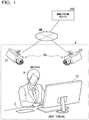
FIG. 1 is a diagram which shows an example of a configuration of amonitoring system 1 of an embodiment. Themonitoring system 1 includes, for example, aninput terminal 10, one ormore monitoring cameras 50, and amonitoring device 100. Themonitoring cameras 50 and themonitoring device 100 are connected to each other by a network NW, and communicate with each other via the network NW. The network NW includes, for example, some or all of a wide area network (WAN), a local area network (LAN), the Internet, a dedicated line, a wireless base station, a provider, and the like. - The
input terminal 10 is installed in a work area A and operated by an inputter B. The inputter B prepares a sheet C on which information to be input is described at hand. The inputter B inputs the information to be input described on the sheet C to theinput terminal 10 by operating, for example, a keyboard. Note that theinput terminal 10 has a voice recognition function, and the information to be input may be input thereto on the basis of information collected by a microphone. Theinput terminal 10 is, for example, a tablet terminal or a personal computer. -
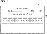
FIG. 2 is a diagram which shows an example of the sheet C. Information to be input C1 is described on the sheet C. The information to be input C1 has, for example, 16 characters or numbers, and is described in a frame. Additional information such as identification information, a type, or a date of the information to be input C1 may also be described on the sheet C. - The
monitoring cameras 50 capture an image of the work area A and generate captured image data. The captured image data may be still image data, and may also be moving image data. Hereinafter, the captured image data may be referred to as a captured image. Themonitoring cameras 50 transmit the generated captured image to themonitoring device 100 via the network NW. A plurality ofmonitoring cameras 50 are installed in, for example, the work area A, and include amonitoring camera 51 that captures a state of work from a side behind the inputter B, amonitoring camera 52 that captures a face of the inputter B from a side in front of the inputter B, and the like. The work area A is not limited to one area, and may be plural areas. In addition, a plurality of work areas A may be prepared in the same room or may be prepared in different rooms. - A monitoring person monitors a state in the work area A while viewing an image that is processed by the
monitoring device 100 for a captured image captured by themonitoring camera 50. -
FIG. 3 is a diagram which shows an example of a configuration of themonitoring device 100. Themonitoring device 100 includes, for example, acommunication device 110, aninput device 120, adisplay device 130, afirst storage 140, asecond storage 150, animage processor 160, and asystem controller 170. - The
communication device 110 includes hardware for connecting to the network NW using a cellular network, a Wi-Fi network, or the like. For example, thecommunication device 110 includes an antenna, a transmitter/receiver, and the like. Theinput device 120 includes, for example, some or all of various keys, buttons, dial switches, a mouse, a microphone, a touch panel formed integrally with thedisplay device 130, and the like. Thedisplay device 130 may include, for example, a liquid crystal display (LCD) or an organic electroluminescence (EL) display device. Thedisplay device 130 may include a speaker, a lamp, and the like. - The
first storage 140 and thesecond storage 150 are realized by, for example, a random access memory (RAM), a flash memory, an SD card, a register, and the like. Thefirst storage 140 temporarily stores a captured image generated by themonitoring cameras 50 as capturedimage data 141. In addition, thefirst storage 140stores history data 142. Thehistory data 142 is information in which the information to be input is associated with an image generated on the basis of the information to be input. Thesecond storage 150 may be an external storage device such as a network attached storage (NAS) which can be accessed by themonitoring device 100 via the network. Thesecond storage 150 stores replacedimage data 151 generated by theimage processor 160 and a history. - The
image processor 160 includes, for example, anacquirer 161, anextractor 162, anencryption processor 163, agenerator 164, adeterminer 165, and adeleter 166. Some or all of these components are realized by, for example, a processor such as a central processing unit (CPU) executing a program (software) stored in thefirst storage 140. In addition, some or all of functions of these components may be realized by hardware (circuit unit: including circuitry) such as a large scale integration (LSI), an application specific integrated circuit (ASIC), a field-programmable gate array (FPGA), or a graphics processing unit (GPU), and may also be realized by cooperation of software and hardware. The program may be stored in advance in a storage device such as a hard disk drive (HDD) or a flash memory, or may also be stored in a detachable storage medium such as a DVD or a CD-ROM and installed by the storage medium being mounted in a drive device. - When the captured image is moving image data, the
image processor 160 executes the following processing for each frame included in the moving image data. - The
acquirer 161 acquires captured images from themonitoring cameras 50 using thecommunication device 110. - The
acquirer 161 temporarily stores the acquired captured image in thefirst storage 140. An example of the captured image is shown inFIG. 4 . A captured image D10 shown inFIG. 4 is an image captured from behind the inputter B by the monitoringcamera 51. - The
extractor 162 extracts the information to be input from the captured image acquired by theacquirer 161. For example, theextractor 162 recognizes the information to be input on the basis of a predetermined format of information to be input and extracts a target image including the recognized information to be input by performing an image analysis on the captured image using a character recognition technology. The character recognition technology is a technology that recognizes characters or numbers contained in an image. - The "predetermined format of information to be input" includes, for example, a character string composed of a predetermined number of characters, a format composed of a predetermined number of numbers, a format that is a combination of characters and numbers and in which positions of the characters and positions of the numbers are predetermined, and the like. In addition, the predetermined format of information to be input may include an arrangement of characters or numbers, an arrangement of characters or numbers horizontally in a row, an arrangement of characters or numbers vertically in two columns, and the like.
- The
extractor 162 extracts information to be input on the basis of, for example, an input area associated with the "predetermined format of information to be input." The input area includes, for example, a frame printed on the sheet C as shown inFIG. 2 , an input field displayed on the monitor of theinput terminal 10, and the like. Thereby, theextractor 162 can extract information to be input even when part of the information to be input is displayed on the monitor while being input. In addition, theextractor 162 may recognize all the characters or numbers included in a captured image, and extract characters or numbers that match the predetermined format of information to be input among the recognized characters or numbers as information to be input. - The
extractor 162 determines an image area (hereinafter, described as a target area) that includes the extracted information to be input and cuts out an image of the target area (hereinafter, described as a target image). For example, theextractor 162 may determine a target area in accordance with the input area. Theextractor 162, not limited thereto, may determine a target area in accordance with a circumscribed minimum rectangle of the recognized characters or numbers. The circumscribed minimum rectangle is a rectangular figure that is set such that a string of characters or numbers (which may be one character or number) recognized as information to be input does not protrude therefrom, and has the smallest area. Theextractor 162 may determine the target area by providing a predetermined margin outside the input area or the circumscribed minimum rectangle. - For example, the
extractor 162 extracts a target image D11 including information to be input that has been displayed on the sheet C and a target image D12 including information to be input that has been displayed on the monitor of theinput terminal 10 from the captured image D10 shown inFIG. 4 . - The
encryption processor 163 encrypts the information to be input that has been extracted by theextractor 162 and generates encrypted information. The encrypted information includes characters (hiragana, katakana, alphabet, and the like), numbers, and the like. For example, theencryption processor 163 encrypts information to be input using a predetermined encryption algorithm. - Various algorithms can be used for encryption processing. For example, the
encryption processor 163 may perform encryption using key information and may also perform encryption according to a predetermined rule. Moreover, theencryption processor 163 may generate key information for performing decryption in the encryption processing. - The
generator 164 generates a partial image on the basis of information encrypted by theencryption processor 163. The partial image is, for example, an image in which the information to be input is made invisible and is an image that displays information for acquiring encrypted information generated by theencryption processor 163. - The
generator 164 generates a partial image in which the encrypted information is superimposed on a filled image (a mask image). In addition, thegenerator 164 may generate a partial image that displays a code obtained by encoding encrypted information (including a one-dimensional code, a two-dimensional code, and the like), or may also generate a mosaic image in which the encrypted information is embedded as a partial image. - The partial image, not limited thereto, may be an image in which the information to be input is made invisible, and may also be an image that displays information for acquiring key information for decrypting information that has been encrypted by the
encryption processor 163. For example, thegenerator 164 may generate a partial image in which the key information is superimposed on the filled image. In addition, thegenerator 164 may also generate a partial image that displays a code obtained by encoding the key information, and may also generate a mosaic image in which the key information is embedded as a partial image. - The
generator 164 generates a replaced image in which the information to be input is made invisible by displaying the partial image in the target area (a position of the information to be input) instead of the target image in the captured image acquired by theacquirer 161. Thegenerator 164 outputs the generated replaced image to thesystem controller 170. -
FIG. 5 is a diagram which shows an example of a replaced image. A replaced image data D20 includes a partial image D21 which is replaced with the target image D11, and a partial image D22 which is replaced with the target image D12. - The partial image D21 and the partial image D22 are the same in the example shown in
FIG. 5 , but the present invention is not limited thereto. For example, the partial image D21 and the partial image D22 may include different encrypted information if information to be input is being input. Specifically, information to be input that has been extracted at a time when three characters are input and information to be input that has been extracted at a time when ten characters are input are different. For this reason, the encrypted information may change during an input and a different image may be displayed in a replaced image, and encrypted information displayed in a target area included in the monitor may switch each time a character is input. - The
generator 164 stores information to be input that has been extracted by theextractor 162 and a partial image generated on the basis of the information to be input in thehistory data 142 in association with each other. - The
determiner 165 determines whether the information to be input that has been extracted by theextractor 162 matches the information to be input that has been already encrypted by theencryption processor 163. For example, thedeterminer 165 refers to thehistory data 142 and determines whether the information to be input that has been extracted by theextractor 162 is registered. When thedeterminer 165 determines that the extracted information to be input matches information to be input that has been already encrypted, thegenerator 164 generates a replaced image on the basis of a partial image read from thehistory data 142 without performing processing of generating a partial image. - The
deleter 166 deletes an associated captured image from thefirst storage 140 when a replaced image is generated by thegenerator 164. In addition, thedeleter 166 may also delete a captured image whose storage period has exceeded a threshold value. - When it is instructed to decrypt the encrypted information included in the replaced image using the
input device 120, thedecryption processor 167 decrypts the encrypted information on the basis of the replaced image to be input by thesystem controller 170. Thedecryption processor 167 outputs the decrypted information to thesystem controller 170 and causes thedisplay device 130 to display it. - The
system controller 170 includes, for example, adata manager 171 and adisplay controller 172. Some or all of these components are realized by, for example, a processor such as a CPU executing a program (software) stored in thesecond storage 150. Moreover, some or all of functions of these components may be realized by hardware such as a LSI, an ASIC, a FPGA, or a GPU, or may also be realized by cooperation between software and hardware. - The
data manager 171 stores the replaced image generated by thegenerator 164 in thesecond storage 150, instead of the captured image captured by the monitoringcamera 50. - The
display controller 172 causes thedisplay device 130 to display the replaced image generated by thegenerator 164, instead of the captured image captured by the monitoringcamera 50. Thedisplay controller 172 may cause thedisplay device 130 to display the replaced image on the basis of a replaced image input from theimage processor 160, or may read a replaced image stored in thesecond storage 150 by thedata management unit 171 and cause thedisplay device 130 to display it. - In addition, when it is instructed to view a past image, the
display controller 172 reads the instructed replaced image from thesecond storage 150 and causes thedisplay device 130 to display it. When it is instructed to decrypt the encrypted information using theinput device 120, thedisplay controller 172 causes thedisplay device 130 to display information to be input decrypted by thedecryption processor 167. -
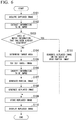
FIG. 6 is a flowchart which shows an example of processing performed by themonitoring device 100. Themonitoring device 100 executes the following processing for each captured image. When a captured image is part of a moving image, themonitoring device 100 executes the following processing for each frame included in an operation. - First, the
acquirer 161 acquires a captured image from themonitoring cameras 50 using the communication device 110 (step S101). Theextractor 162 extracts information to be input from the captured image acquired by the acquirer 161 (step S102). Thedeterminer 165 refers to thehistory data 142 and determines whether the information to be input that has been extracted by theextractor 162 matches information to be input that has been already encrypted by the encryption processor 163 (step S103). - When the information to be input that has been extracted by the
extractor 162 does not match the information to be input that has been already encrypted by theencryption processor 163, theextractor 162 determines a target area (step S104) and cuts off the determined target area (step S105). Theencryption processor 163 encrypts the information to be input that has been extracted by the extractor 162 (step S106). Thegenerator 164 generates a partial image on the basis of information encrypted by the encryption processor 163 (step S107). Next, thegenerator 164 generates a replaced image that displays the partial image in the target area in which a target image is cut out in step S105 (step S108). Then, thegenerator 164 outputs the replaced image to thesystem controller 170. - The
data manager 171 stores the replaced image output from thegenerator 164 in the second storage 150 (step S109). Thedisplay controller 172 causes thedisplay device 130 to display the replaced image generated by the generator 164 (step S110). - On the other hand, when the information to be input that has been extracted by the
extractor 162 matches the information to be input that has been already encrypted by theencryption processor 163 in step S103, thegenerator 164 reads a partial image associated with the information to be input that has been extracted by theextractor 162 from thefirst storage 140, and generates a replaced image on the basis of the read partial image (step S111). For example, step S111 is executed at a timing at which the same information to be input as the information to be input that has been already encrypted is extracted from the captured image. Since the information to be input that has been displayed on the sheet C on an image does not change during input work, thegenerator 164 uses a partial image that has been first generated when information to be input is captured by the monitoringcamera 50, and causes it to be displayed in a target area associated with information to be input that has been extracted from a captured image thereafter. - In this manner, the
monitoring device 100 can cause thedisplay device 130 to display the replaced image in which the information to be input is not displayed. Accordingly, it is possible to keep the information to be input secret from a monitoring person who monitors a work area A while viewing thedisplay device 130. Confidentiality obligation is often imposed on the inputter B, but there are some cases where the confidentiality obligation is not imposed on the monitoring person. It is especially beneficial in this case. - In addition, the
monitoring device 100 can cause thedisplay device 130 to display a replaced image including encrypted information and the like or transmit the replaced image to an external device having a monitor at the time of monitoring almost in real time by a monitoring person or at the time of viewing a past image. Thereby, information to be input can be acquired by decrypting the information to be input that is made invisible using encrypted information and the like displayed in the replaced image. Therefore, the information to be input can be easily acquired even when there is a situation in which associating of the information to be input with the captured image captured by the monitoringcamera 50 later and checking of it are required. On the other hand, when a captured image is an image which is obtained by merely replacing a target area with a mask image, since it is impossible to associate the information to be input with the captured image thereafter and to check it even when there is a situation in which the associating and the checking are required later, which is inconvenient. - According to at least one embodiment described above, it is possible to check information to be input when checking of the information to be input is required while making the information to be input invisible on the replaced screen by including an acquirer configured to acquire, from one or more monitoring cameras that capture an image of a work area in which presented information to be input is input to an input terminal, a captured image captured by the one or more monitoring cameras, an extractor configured to extract the information to be input from the captured image acquired by the acquirer, an encryption processor configured to encrypt the information to be input extracted by the extractor, and a generator configured to generate a replaced image in which the information to be input is made invisible, the replaced image including a partial image that displays information encrypted by the encryption processor at a position of the information to be input in the captured image acquired by the acquirer. Therefore, it is possible to improve a convenience in a system that masks part of the monitoring camera.
- Although some embodiments of the present invention have been described, these embodiments are presented as examples and are not intended to limit the scope of the invention. These embodiments can be implemented in various other forms, and various omission, replacements, and changes can be made in a range not departing from the spirit of the invention. These embodiments and modifications thereof are included in the scope and spirit of the invention, as well as in the scope of the invention described in the claims and the equivalent scope thereof.
- For example, the
image processor 160 may execute different processing in accordance with a subject including a target area in a captured image. For example, the different processing may also be executed when the subject including a target area is the sheet C, and when the subject including a target area is the monitor of theinput terminal 10. This is because information to be input in the monitor changes according to input work although information to be input on the sheet C of an image does not change. A specific example thereof will be described below. - The
image processor 160 generates a partial image in the sheet C on an image on the basis of encrypted information obtained by encrypting information to be input that has been extracted from the sheet C on the image. On the other hand, theimage processor 160 generates a partial image in the monitor on an image on the basis of the encrypted information obtained by encrypting the information to be input that has been extracted from the sheet C on an image instead of information to be input that has been extracted from the monitor on the image. Thereby, a processing load of the encryption processing can be reduced. In addition, the information to be input that is extracted from the monitor changes during an input, but, even in such a situation, partial images including the same encrypted information can be displayed and a replaced screen can be made easier to view. - In addition, the
encryption processor 163 may also change an algorithm of encrypting a captured image when a predetermined switching timing is reached. The predetermined switching timing includes a case in which a predetermined time has been elapsed, a case in which extracted information to be input is different from information to be input that has been previously extracted, a case in which a predetermined format of information to be input is different from a previous format, and the like. Moreover, theencryption processor 163 may also change an algorithm of encrypting a captured image in accordance with the predetermined format of information to be input. -
- 1 Monitoring system
- 10 Input terminal
- 50 Monitoring camera
- 100 Monitoring device
- 110 Communication device
- 120 Input device
- 130 Display device
- 140 First storage
- 150 Second storage
- 160 Image processor
- 161 Acquirer
- 162 Extractor
- 163 Encryption processor
- 164 Generator
- 165 Determiner
- 166 Deleter
- 170 System controller
- 171 Data manager
- 172 Display controller
Claims (8)
- A monitoring system comprising:an acquirer configured to acquire, from one or more monitoring cameras that capture an image of a work area in which presented information to be input is input to an input terminal, a captured image captured by the one or more monitoring cameras;an extractor configured to extract the information to be input from the captured image acquired by the acquirer;an encryption processor configured to encrypt the information to be input extracted by the extractor; anda generator configured to generate a replaced image in which the information to be input is made invisible, the replaced image comprising a partial image that displays information encrypted by the encryption processor at a position of the information to be input in the captured image acquired by the acquirer.
- A monitoring system comprising:an acquirer configured to acquire, from one or more monitoring cameras that capture an image of a work area in which presented information to be input is input to an input terminal, a captured image captured by the one or more monitoring cameras;an extractor configured to extract the information to be input from the captured image acquired by the acquirer;an encryption processor configured to encrypt the information to be input extracted by the extractor; anda generator configured to generate a replaced image in which the information to be input is made invisible, the replaced image comprising a partial image that displays key information for decrypting information encrypted by the encryption processor at a position of the information to be input in the captured image acquired by the acquirer.
- The monitoring system according to claim 1 or 2, further comprising:
a data manager configured to cause a storage to store the captured image captured by the one or more monitoring cameras, and, in a case where the replaced image is generated by the generator, to cause the storage to store the replaced image instead of the captured image. - The monitoring system according to any one of claims 1 to 3, further comprising:
a display controller configured to cause a display device to display the captured image captured by the one or more monitoring cameras, and, in a case where the replaced image is generated by the generator, to cause the display device to display the replaced image instead of the captured image. - The monitoring system according to any one of claims 1 to 4, further comprising:a determiner configured to determine whether the information to be input extracted by the extractor matches the information to be input that has been encrypted by the encryption processor,wherein, in a case where the determiner determines that the information to be input extracted by the extractor matches the information to be input that has been encrypted by the encryption processor, the generator generates the replaced image on the basis of the invisible image already converted by the encryption processor.
- The monitoring system according to any one of claims 1 to 5,
wherein, in a case where a predetermined switching timing is reached, the encryption processor changes an algorithm for encrypting the captured image. - A monitoring method comprising:by a computer,acquiring, from one or more monitoring cameras that capture an image of a work area in which presented information to be input is input to an input terminal, a captured image captured by the one or more monitoring cameras;extracting the information to be input from the acquired captured image;encrypting the extracted information to be input; andgenerating a replaced image in which the information to be input is made invisible, the replaced image comprising a partial image that displays encrypted information at a position of the information to be input in the captured image.
- A program that causes a computer to execute:acquiring, from one or more monitoring cameras that capture an image of a work area in which presented information to be input is input to an input terminal, a captured image captured by the one or more monitoring cameras;extracting the information to be input from the acquired captured image;encrypting the extracted information to be input; andgenerating a replaced image in which the information to be input is made invisible, the replaced image comprising a partial image that displays encrypted information at a position of the information to be input in the captured image.
Applications Claiming Priority (2)
| Application Number | Priority Date | Filing Date | Title |
|---|---|---|---|
| JP2018154186A JP7134784B2 (en) | 2018-08-20 | 2018-08-20 | Monitoring system, monitoring method and program |
| PCT/JP2019/032252 WO2020040080A1 (en) | 2018-08-20 | 2019-08-19 | Monitoring system, monitoring method, and program |
Publications (3)
| Publication Number | Publication Date |
|---|---|
| EP3843381A1 true EP3843381A1 (en) | 2021-06-30 |
| EP3843381A4 EP3843381A4 (en) | 2022-05-18 |
| EP3843381B1 EP3843381B1 (en) | 2024-08-07 |
Family
ID=69593096
Family Applications (1)
| Application Number | Title | Priority Date | Filing Date |
|---|---|---|---|
| EP19852847.3A Active EP3843381B1 (en) | 2018-08-20 | 2019-08-19 | Monitoring system, monitoring method, and program |
Country Status (5)
| Country | Link |
|---|---|
| US (1) | US11463659B2 (en) |
| EP (1) | EP3843381B1 (en) |
| JP (1) | JP7134784B2 (en) |
| SG (1) | SG11202101636VA (en) |
| WO (1) | WO2020040080A1 (en) |
Family Cites Families (19)
| Publication number | Priority date | Publication date | Assignee | Title |
|---|---|---|---|---|
| JP3522635B2 (en) * | 1999-08-03 | 2004-04-26 | ヴィジョンアーツ株式会社 | Computer-readable recording medium recording an image file, apparatus for creating this recording medium, medium recording an image file creation program, image file transmitting apparatus, image file processing apparatus, medium recording image file processing program |
| JP3722653B2 (en) | 1999-08-31 | 2005-11-30 | 松下電器産業株式会社 | Surveillance camera device and display method of surveillance camera |
| JP2003153252A (en) * | 2001-11-13 | 2003-05-23 | Toshiba Corp | Remote monitoring system and image processing device |
| JP4036051B2 (en) | 2002-07-30 | 2008-01-23 | オムロン株式会社 | Face matching device and face matching method |
| JP4402998B2 (en) * | 2004-03-29 | 2010-01-20 | 三菱電機株式会社 | Surveillance system and camera with masking function, and mask release device used with the camera |
| JP2005323007A (en) | 2004-05-06 | 2005-11-17 | Matsushita Electric Ind Co Ltd | Recording / reproducing apparatus and recording / reproducing method |
| CN101167361A (en) | 2005-04-25 | 2008-04-23 | 松下电器产业株式会社 | Surveillance camera system, photography device and video display device |
| JP4975272B2 (en) * | 2005-05-30 | 2012-07-11 | 京セラ株式会社 | User terminal |
| US8938671B2 (en) * | 2005-12-16 | 2015-01-20 | The 41St Parameter, Inc. | Methods and apparatus for securely displaying digital images |
| KR100877747B1 (en) * | 2006-10-18 | 2009-01-12 | 포스데이타 주식회사 | Digital video recorder and its input image protection device and method |
| JP2009177699A (en) * | 2008-01-28 | 2009-08-06 | Oki Data Corp | Image forming apparatus |
| JP5169641B2 (en) | 2008-09-02 | 2013-03-27 | 富士通株式会社 | Image analysis apparatus and image analysis program |
| JP5489340B2 (en) | 2010-03-12 | 2014-05-14 | パナソニック株式会社 | Face masking apparatus and method |
| US8823798B2 (en) * | 2011-12-23 | 2014-09-02 | Xerox Corporation | Obscuring identification information in an image of a vehicle |
| US10489603B2 (en) * | 2015-03-19 | 2019-11-26 | Kbytes Solutions Private Limited | Method and apparatus for image privacy protection |
| JP6624852B2 (en) * | 2015-08-27 | 2019-12-25 | キヤノン株式会社 | Image information generation device, image information generation method, image processing system, and program |
| CN108206930A (en) * | 2016-12-16 | 2018-06-26 | 杭州海康威视数字技术股份有限公司 | The method and device for showing image is covered based on privacy |
| JP7047394B2 (en) * | 2018-01-18 | 2022-04-05 | セイコーエプソン株式会社 | Head-mounted display device, display system, and control method for head-mounted display device |
| US11301897B2 (en) * | 2018-04-11 | 2022-04-12 | Intel Corporation | Secure visual transactions for mobile devices |
-
2018
- 2018-08-20 JP JP2018154186A patent/JP7134784B2/en active Active
-
2019
- 2019-08-19 WO PCT/JP2019/032252 patent/WO2020040080A1/en not_active Ceased
- 2019-08-19 EP EP19852847.3A patent/EP3843381B1/en active Active
- 2019-08-19 SG SG11202101636VA patent/SG11202101636VA/en unknown
-
2021
- 2021-02-17 US US17/177,308 patent/US11463659B2/en active Active
Also Published As
| Publication number | Publication date |
|---|---|
| JP2020031280A (en) | 2020-02-27 |
| US20210168333A1 (en) | 2021-06-03 |
| JP7134784B2 (en) | 2022-09-12 |
| EP3843381A4 (en) | 2022-05-18 |
| US11463659B2 (en) | 2022-10-04 |
| WO2020040080A1 (en) | 2020-02-27 |
| SG11202101636VA (en) | 2021-03-30 |
| EP3843381B1 (en) | 2024-08-07 |
Similar Documents
| Publication | Publication Date | Title |
|---|---|---|
| US9947012B2 (en) | Secure transactions using a personal device | |
| US9679126B2 (en) | Decryption device, method for decrypting and method and system for secure data transmission | |
| EP3220573B1 (en) | Method and system for controlling encryption of information and analyzing information as well as terminal | |
| RU2656685C1 (en) | Password formation method and device for its implementation | |
| EP2950272B1 (en) | Method and apparatus for processing a video frame in a video file | |
| CN107666479A (en) | Information encrypting and decrypting method, apparatus, computer equipment and storage medium | |
| US20180068423A1 (en) | Image processing apparatus, image processing method, and storage medium | |
| EP3703334B1 (en) | Unlocking method and system for air conditioner unit | |
| CN117375817A (en) | End-to-end encryption method and device for instant messaging data, electronic equipment and medium | |
| US20170249450A1 (en) | Device and Method for Authenticating a User | |
| US10003462B2 (en) | Key generating method and apparatus | |
| EP3843381B1 (en) | Monitoring system, monitoring method, and program | |
| CN105933503B (en) | Information processing method and electronic equipment | |
| US10430617B2 (en) | Terminal determination device and method | |
| CN112270004B (en) | Content encryption method, device and electronic device | |
| CN113485611B (en) | Image display method and device and electronic equipment | |
| US10055599B2 (en) | Processing method for making electronic documents secure | |
| CN113127899A (en) | RFID-based archive processing method, device, equipment and storage medium | |
| CN113835820A (en) | Graphic code display method and device | |
| JP2013027011A (en) | Image management apparatus, image management program, and image management method | |
| CN113360879B (en) | Display control method, display control device, electronic equipment and medium | |
| JP6665590B2 (en) | Information processing apparatus, information processing method, program, and information processing system | |
| CN116418566A (en) | SM encryption algorithm-based image data storage method and device | |
| CN112396008A (en) | Sensitive information desensitization method and device, storage medium and electronic equipment | |
| CN110717078A (en) | Beauty shop business data monitoring method, device, equipment and medium |
Legal Events
| Date | Code | Title | Description |
|---|---|---|---|
| STAA | Information on the status of an ep patent application or granted ep patent |
Free format text: STATUS: THE INTERNATIONAL PUBLICATION HAS BEEN MADE |
|
| PUAI | Public reference made under article 153(3) epc to a published international application that has entered the european phase |
Free format text: ORIGINAL CODE: 0009012 |
|
| STAA | Information on the status of an ep patent application or granted ep patent |
Free format text: STATUS: REQUEST FOR EXAMINATION WAS MADE |
|
| 17P | Request for examination filed |
Effective date: 20210219 |
|
| AK | Designated contracting states |
Kind code of ref document: A1 Designated state(s): AL AT BE BG CH CY CZ DE DK EE ES FI FR GB GR HR HU IE IS IT LI LT LU LV MC MK MT NL NO PL PT RO RS SE SI SK SM TR |
|
| DAV | Request for validation of the european patent (deleted) | ||
| DAX | Request for extension of the european patent (deleted) | ||
| A4 | Supplementary search report drawn up and despatched |
Effective date: 20220421 |
|
| RIC1 | Information provided on ipc code assigned before grant |
Ipc: G06F 21/84 20130101ALI20220413BHEP Ipc: G06F 21/62 20130101ALI20220413BHEP Ipc: H04N 7/18 20060101AFI20220413BHEP |
|
| GRAP | Despatch of communication of intention to grant a patent |
Free format text: ORIGINAL CODE: EPIDOSNIGR1 |
|
| STAA | Information on the status of an ep patent application or granted ep patent |
Free format text: STATUS: GRANT OF PATENT IS INTENDED |
|
| INTG | Intention to grant announced |
Effective date: 20240312 |
|
| GRAS | Grant fee paid |
Free format text: ORIGINAL CODE: EPIDOSNIGR3 |
|
| GRAA | (expected) grant |
Free format text: ORIGINAL CODE: 0009210 |
|
| STAA | Information on the status of an ep patent application or granted ep patent |
Free format text: STATUS: THE PATENT HAS BEEN GRANTED |
|
| AK | Designated contracting states |
Kind code of ref document: B1 Designated state(s): AL AT BE BG CH CY CZ DE DK EE ES FI FR GB GR HR HU IE IS IT LI LT LU LV MC MK MT NL NO PL PT RO RS SE SI SK SM TR |
|
| REG | Reference to a national code |
Ref country code: GB Ref legal event code: FG4D |
|
| REG | Reference to a national code |
Ref country code: CH Ref legal event code: EP |
|
| REG | Reference to a national code |
Ref country code: IE Ref legal event code: FG4D |
|
| REG | Reference to a national code |
Ref country code: DE Ref legal event code: R096 Ref document number: 602019056735 Country of ref document: DE |
|
| REG | Reference to a national code |
Ref country code: LT Ref legal event code: MG9D |
|
| REG | Reference to a national code |
Ref country code: NL Ref legal event code: MP Effective date: 20240807 |
|
| PG25 | Lapsed in a contracting state [announced via postgrant information from national office to epo] |
Ref country code: NO Free format text: LAPSE BECAUSE OF FAILURE TO SUBMIT A TRANSLATION OF THE DESCRIPTION OR TO PAY THE FEE WITHIN THE PRESCRIBED TIME-LIMIT Effective date: 20241107 |
|
| REG | Reference to a national code |
Ref country code: AT Ref legal event code: MK05 Ref document number: 1712175 Country of ref document: AT Kind code of ref document: T Effective date: 20240807 |
|
| PG25 | Lapsed in a contracting state [announced via postgrant information from national office to epo] |
Ref country code: FI Free format text: LAPSE BECAUSE OF FAILURE TO SUBMIT A TRANSLATION OF THE DESCRIPTION OR TO PAY THE FEE WITHIN THE PRESCRIBED TIME-LIMIT Effective date: 20240807 Ref country code: GR Free format text: LAPSE BECAUSE OF FAILURE TO SUBMIT A TRANSLATION OF THE DESCRIPTION OR TO PAY THE FEE WITHIN THE PRESCRIBED TIME-LIMIT Effective date: 20241108 Ref country code: NL Free format text: LAPSE BECAUSE OF FAILURE TO SUBMIT A TRANSLATION OF THE DESCRIPTION OR TO PAY THE FEE WITHIN THE PRESCRIBED TIME-LIMIT Effective date: 20240807 Ref country code: PT Free format text: LAPSE BECAUSE OF FAILURE TO SUBMIT A TRANSLATION OF THE DESCRIPTION OR TO PAY THE FEE WITHIN THE PRESCRIBED TIME-LIMIT Effective date: 20241209 Ref country code: PL Free format text: LAPSE BECAUSE OF FAILURE TO SUBMIT A TRANSLATION OF THE DESCRIPTION OR TO PAY THE FEE WITHIN THE PRESCRIBED TIME-LIMIT Effective date: 20240807 |
|
| PG25 | Lapsed in a contracting state [announced via postgrant information from national office to epo] |
Ref country code: BG Free format text: LAPSE BECAUSE OF FAILURE TO SUBMIT A TRANSLATION OF THE DESCRIPTION OR TO PAY THE FEE WITHIN THE PRESCRIBED TIME-LIMIT Effective date: 20240807 |
|
| PG25 | Lapsed in a contracting state [announced via postgrant information from national office to epo] |
Ref country code: LV Free format text: LAPSE BECAUSE OF FAILURE TO SUBMIT A TRANSLATION OF THE DESCRIPTION OR TO PAY THE FEE WITHIN THE PRESCRIBED TIME-LIMIT Effective date: 20240807 |
|
| PG25 | Lapsed in a contracting state [announced via postgrant information from national office to epo] |
Ref country code: AT Free format text: LAPSE BECAUSE OF FAILURE TO SUBMIT A TRANSLATION OF THE DESCRIPTION OR TO PAY THE FEE WITHIN THE PRESCRIBED TIME-LIMIT Effective date: 20240807 Ref country code: IS Free format text: LAPSE BECAUSE OF FAILURE TO SUBMIT A TRANSLATION OF THE DESCRIPTION OR TO PAY THE FEE WITHIN THE PRESCRIBED TIME-LIMIT Effective date: 20241207 |
|
| PG25 | Lapsed in a contracting state [announced via postgrant information from national office to epo] |
Ref country code: HR Free format text: LAPSE BECAUSE OF FAILURE TO SUBMIT A TRANSLATION OF THE DESCRIPTION OR TO PAY THE FEE WITHIN THE PRESCRIBED TIME-LIMIT Effective date: 20240807 |
|
| PG25 | Lapsed in a contracting state [announced via postgrant information from national office to epo] |
Ref country code: ES Free format text: LAPSE BECAUSE OF FAILURE TO SUBMIT A TRANSLATION OF THE DESCRIPTION OR TO PAY THE FEE WITHIN THE PRESCRIBED TIME-LIMIT Effective date: 20240807 Ref country code: RS Free format text: LAPSE BECAUSE OF FAILURE TO SUBMIT A TRANSLATION OF THE DESCRIPTION OR TO PAY THE FEE WITHIN THE PRESCRIBED TIME-LIMIT Effective date: 20241107 |
|
| PG25 | Lapsed in a contracting state [announced via postgrant information from national office to epo] |
Ref country code: RS Free format text: LAPSE BECAUSE OF FAILURE TO SUBMIT A TRANSLATION OF THE DESCRIPTION OR TO PAY THE FEE WITHIN THE PRESCRIBED TIME-LIMIT Effective date: 20241107 Ref country code: PT Free format text: LAPSE BECAUSE OF FAILURE TO SUBMIT A TRANSLATION OF THE DESCRIPTION OR TO PAY THE FEE WITHIN THE PRESCRIBED TIME-LIMIT Effective date: 20241209 Ref country code: PL Free format text: LAPSE BECAUSE OF FAILURE TO SUBMIT A TRANSLATION OF THE DESCRIPTION OR TO PAY THE FEE WITHIN THE PRESCRIBED TIME-LIMIT Effective date: 20240807 Ref country code: NO Free format text: LAPSE BECAUSE OF FAILURE TO SUBMIT A TRANSLATION OF THE DESCRIPTION OR TO PAY THE FEE WITHIN THE PRESCRIBED TIME-LIMIT Effective date: 20241107 Ref country code: NL Free format text: LAPSE BECAUSE OF FAILURE TO SUBMIT A TRANSLATION OF THE DESCRIPTION OR TO PAY THE FEE WITHIN THE PRESCRIBED TIME-LIMIT Effective date: 20240807 Ref country code: LV Free format text: LAPSE BECAUSE OF FAILURE TO SUBMIT A TRANSLATION OF THE DESCRIPTION OR TO PAY THE FEE WITHIN THE PRESCRIBED TIME-LIMIT Effective date: 20240807 Ref country code: IS Free format text: LAPSE BECAUSE OF FAILURE TO SUBMIT A TRANSLATION OF THE DESCRIPTION OR TO PAY THE FEE WITHIN THE PRESCRIBED TIME-LIMIT Effective date: 20241207 Ref country code: HR Free format text: LAPSE BECAUSE OF FAILURE TO SUBMIT A TRANSLATION OF THE DESCRIPTION OR TO PAY THE FEE WITHIN THE PRESCRIBED TIME-LIMIT Effective date: 20240807 Ref country code: GR Free format text: LAPSE BECAUSE OF FAILURE TO SUBMIT A TRANSLATION OF THE DESCRIPTION OR TO PAY THE FEE WITHIN THE PRESCRIBED TIME-LIMIT Effective date: 20241108 Ref country code: FI Free format text: LAPSE BECAUSE OF FAILURE TO SUBMIT A TRANSLATION OF THE DESCRIPTION OR TO PAY THE FEE WITHIN THE PRESCRIBED TIME-LIMIT Effective date: 20240807 Ref country code: ES Free format text: LAPSE BECAUSE OF FAILURE TO SUBMIT A TRANSLATION OF THE DESCRIPTION OR TO PAY THE FEE WITHIN THE PRESCRIBED TIME-LIMIT Effective date: 20240807 Ref country code: BG Free format text: LAPSE BECAUSE OF FAILURE TO SUBMIT A TRANSLATION OF THE DESCRIPTION OR TO PAY THE FEE WITHIN THE PRESCRIBED TIME-LIMIT Effective date: 20240807 Ref country code: AT Free format text: LAPSE BECAUSE OF FAILURE TO SUBMIT A TRANSLATION OF THE DESCRIPTION OR TO PAY THE FEE WITHIN THE PRESCRIBED TIME-LIMIT Effective date: 20240807 |
|
| REG | Reference to a national code |
Ref country code: CH Ref legal event code: PL |
|
| PG25 | Lapsed in a contracting state [announced via postgrant information from national office to epo] |
Ref country code: SM Free format text: LAPSE BECAUSE OF FAILURE TO SUBMIT A TRANSLATION OF THE DESCRIPTION OR TO PAY THE FEE WITHIN THE PRESCRIBED TIME-LIMIT Effective date: 20240807 Ref country code: DK Free format text: LAPSE BECAUSE OF FAILURE TO SUBMIT A TRANSLATION OF THE DESCRIPTION OR TO PAY THE FEE WITHIN THE PRESCRIBED TIME-LIMIT Effective date: 20240807 Ref country code: RO Free format text: LAPSE BECAUSE OF FAILURE TO SUBMIT A TRANSLATION OF THE DESCRIPTION OR TO PAY THE FEE WITHIN THE PRESCRIBED TIME-LIMIT Effective date: 20240807 |
|
| PG25 | Lapsed in a contracting state [announced via postgrant information from national office to epo] |
Ref country code: LU Free format text: LAPSE BECAUSE OF NON-PAYMENT OF DUE FEES Effective date: 20240819 |
|
| PG25 | Lapsed in a contracting state [announced via postgrant information from national office to epo] |
Ref country code: CH Free format text: LAPSE BECAUSE OF NON-PAYMENT OF DUE FEES Effective date: 20240831 Ref country code: EE Free format text: LAPSE BECAUSE OF FAILURE TO SUBMIT A TRANSLATION OF THE DESCRIPTION OR TO PAY THE FEE WITHIN THE PRESCRIBED TIME-LIMIT Effective date: 20240807 |
|
| PG25 | Lapsed in a contracting state [announced via postgrant information from national office to epo] |
Ref country code: CZ Free format text: LAPSE BECAUSE OF FAILURE TO SUBMIT A TRANSLATION OF THE DESCRIPTION OR TO PAY THE FEE WITHIN THE PRESCRIBED TIME-LIMIT Effective date: 20240807 |
|
| PG25 | Lapsed in a contracting state [announced via postgrant information from national office to epo] |
Ref country code: SK Free format text: LAPSE BECAUSE OF FAILURE TO SUBMIT A TRANSLATION OF THE DESCRIPTION OR TO PAY THE FEE WITHIN THE PRESCRIBED TIME-LIMIT Effective date: 20240807 |
|
| REG | Reference to a national code |
Ref country code: DE Ref legal event code: R097 Ref document number: 602019056735 Country of ref document: DE |
|
| PLBE | No opposition filed within time limit |
Free format text: ORIGINAL CODE: 0009261 |
|
| STAA | Information on the status of an ep patent application or granted ep patent |
Free format text: STATUS: NO OPPOSITION FILED WITHIN TIME LIMIT |
|
| REG | Reference to a national code |
Ref country code: BE Ref legal event code: MM Effective date: 20240831 |
|
| PG25 | Lapsed in a contracting state [announced via postgrant information from national office to epo] |
Ref country code: MC Free format text: LAPSE BECAUSE OF FAILURE TO SUBMIT A TRANSLATION OF THE DESCRIPTION OR TO PAY THE FEE WITHIN THE PRESCRIBED TIME-LIMIT Effective date: 20240807 |
|
| PG25 | Lapsed in a contracting state [announced via postgrant information from national office to epo] |
Ref country code: BE Free format text: LAPSE BECAUSE OF NON-PAYMENT OF DUE FEES Effective date: 20240831 |
|
| 26N | No opposition filed |
Effective date: 20250508 |
|
| PGFP | Annual fee paid to national office [announced via postgrant information from national office to epo] |
Ref country code: FR Payment date: 20250610 Year of fee payment: 7 |
|
| GBPC | Gb: european patent ceased through non-payment of renewal fee |
Effective date: 20241107 |
|
| PG25 | Lapsed in a contracting state [announced via postgrant information from national office to epo] |
Ref country code: IE Free format text: LAPSE BECAUSE OF NON-PAYMENT OF DUE FEES Effective date: 20240819 |
|
| REG | Reference to a national code |
Ref country code: DE Ref legal event code: R081 Ref document number: 602019056735 Country of ref document: DE Owner name: KABUSHIKI KAISHA TOSHIBA, JP Free format text: FORMER OWNERS: KABUSHIKI KAISHA TOSHIBA, TOKYO, JP; TOSHIBA INFRASTRUCTURE SYSTEMS & SOLUTIONS CORPORATION, KAWASAKI-SHI, KANAGAWA, JP |
|
| PG25 | Lapsed in a contracting state [announced via postgrant information from national office to epo] |
Ref country code: SE Free format text: LAPSE BECAUSE OF FAILURE TO SUBMIT A TRANSLATION OF THE DESCRIPTION OR TO PAY THE FEE WITHIN THE PRESCRIBED TIME-LIMIT Effective date: 20240807 |
|
| PGFP | Annual fee paid to national office [announced via postgrant information from national office to epo] |
Ref country code: DE Payment date: 20250624 Year of fee payment: 7 |
|
| PG25 | Lapsed in a contracting state [announced via postgrant information from national office to epo] |
Ref country code: GB Free format text: LAPSE BECAUSE OF NON-PAYMENT OF DUE FEES Effective date: 20241107 |
|
| PG25 | Lapsed in a contracting state [announced via postgrant information from national office to epo] |
Ref country code: IT Free format text: LAPSE BECAUSE OF FAILURE TO SUBMIT A TRANSLATION OF THE DESCRIPTION OR TO PAY THE FEE WITHIN THE PRESCRIBED TIME-LIMIT Effective date: 20240807 Ref country code: CY Free format text: LAPSE BECAUSE OF FAILURE TO SUBMIT A TRANSLATION OF THE DESCRIPTION OR TO PAY THE FEE WITHIN THE PRESCRIBED TIME-LIMIT; INVALID AB INITIO Effective date: 20190819 |
|
| PG25 | Lapsed in a contracting state [announced via postgrant information from national office to epo] |
Ref country code: HU Free format text: LAPSE BECAUSE OF FAILURE TO SUBMIT A TRANSLATION OF THE DESCRIPTION OR TO PAY THE FEE WITHIN THE PRESCRIBED TIME-LIMIT; INVALID AB INITIO Effective date: 20190819 |