EP3843232A1 - Control device, battery unit, and work machine - Google Patents
Control device, battery unit, and work machine Download PDFInfo
- Publication number
- EP3843232A1 EP3843232A1 EP18935565.4A EP18935565A EP3843232A1 EP 3843232 A1 EP3843232 A1 EP 3843232A1 EP 18935565 A EP18935565 A EP 18935565A EP 3843232 A1 EP3843232 A1 EP 3843232A1
- Authority
- EP
- European Patent Office
- Prior art keywords
- unit
- power
- battery
- electrode
- rectifier element
- Prior art date
- Legal status (The legal status is an assumption and is not a legal conclusion. Google has not performed a legal analysis and makes no representation as to the accuracy of the status listed.)
- Granted
Links
Images



Classifications
-
- H—ELECTRICITY
- H02—GENERATION; CONVERSION OR DISTRIBUTION OF ELECTRIC POWER
- H02J—ELECTRIC POWER NETWORKS; CIRCUIT ARRANGEMENTS OR SYSTEMS FOR SUPPLYING OR DISTRIBUTING ELECTRIC POWER; SYSTEMS FOR STORING ELECTRIC ENERGY
- H02J7/00—Circuit arrangements for charging or discharging batteries or for supplying loads from batteries
- H02J7/32—Circuit arrangements for charging or discharging batteries or for supplying loads from batteries for charging batteries from a charging set comprising a non-electric prime mover rotating at constant speed
-
- H—ELECTRICITY
- H02—GENERATION; CONVERSION OR DISTRIBUTION OF ELECTRIC POWER
- H02J—ELECTRIC POWER NETWORKS; CIRCUIT ARRANGEMENTS OR SYSTEMS FOR SUPPLYING OR DISTRIBUTING ELECTRIC POWER; SYSTEMS FOR STORING ELECTRIC ENERGY
- H02J7/00—Circuit arrangements for charging or discharging batteries or for supplying loads from batteries
- H02J7/90—Regulation of charging or discharging current or voltage
-
- A—HUMAN NECESSITIES
- A01—AGRICULTURE; FORESTRY; ANIMAL HUSBANDRY; HUNTING; TRAPPING; FISHING
- A01D—HARVESTING; MOWING
- A01D34/00—Mowers; Mowing apparatus of harvesters
- A01D34/01—Mowers; Mowing apparatus of harvesters characterised by features relating to the type of cutting apparatus
-
- H—ELECTRICITY
- H02—GENERATION; CONVERSION OR DISTRIBUTION OF ELECTRIC POWER
- H02J—ELECTRIC POWER NETWORKS; CIRCUIT ARRANGEMENTS OR SYSTEMS FOR SUPPLYING OR DISTRIBUTING ELECTRIC POWER; SYSTEMS FOR STORING ELECTRIC ENERGY
- H02J1/00—Circuit arrangements for DC mains or DC distribution networks
- H02J1/10—Parallel operation of DC sources
-
- H—ELECTRICITY
- H02—GENERATION; CONVERSION OR DISTRIBUTION OF ELECTRIC POWER
- H02J—ELECTRIC POWER NETWORKS; CIRCUIT ARRANGEMENTS OR SYSTEMS FOR SUPPLYING OR DISTRIBUTING ELECTRIC POWER; SYSTEMS FOR STORING ELECTRIC ENERGY
- H02J7/00—Circuit arrangements for charging or discharging batteries or for supplying loads from batteries
- H02J7/70—Circuit arrangements for charging or discharging batteries or for supplying loads from batteries characterised by the mechanical construction
- H02J7/751—Circuit arrangements for charging or discharging batteries or for supplying loads from batteries characterised by the mechanical construction concerning the insertion or the connection of the batteries
-
- H—ELECTRICITY
- H02—GENERATION; CONVERSION OR DISTRIBUTION OF ELECTRIC POWER
- H02J—ELECTRIC POWER NETWORKS; CIRCUIT ARRANGEMENTS OR SYSTEMS FOR SUPPLYING OR DISTRIBUTING ELECTRIC POWER; SYSTEMS FOR STORING ELECTRIC ENERGY
- H02J7/00—Circuit arrangements for charging or discharging batteries or for supplying loads from batteries
- H02J7/80—Circuit arrangements for charging or discharging batteries or for supplying loads from batteries including monitoring or indicating arrangements
-
- H—ELECTRICITY
- H02—GENERATION; CONVERSION OR DISTRIBUTION OF ELECTRIC POWER
- H02J—ELECTRIC POWER NETWORKS; CIRCUIT ARRANGEMENTS OR SYSTEMS FOR SUPPLYING OR DISTRIBUTING ELECTRIC POWER; SYSTEMS FOR STORING ELECTRIC ENERGY
- H02J1/00—Circuit arrangements for DC mains or DC distribution networks
- H02J1/10—Parallel operation of DC sources
- H02J1/108—Parallel operation of DC sources having arrangements for blocking reverse current flow, e.g. using diodes
-
- H—ELECTRICITY
- H02—GENERATION; CONVERSION OR DISTRIBUTION OF ELECTRIC POWER
- H02J—ELECTRIC POWER NETWORKS; CIRCUIT ARRANGEMENTS OR SYSTEMS FOR SUPPLYING OR DISTRIBUTING ELECTRIC POWER; SYSTEMS FOR STORING ELECTRIC ENERGY
- H02J2207/00—Details of circuit arrangements for charging or discharging batteries or supplying loads from batteries
- H02J2207/40—Details of circuit arrangements for charging or discharging batteries or supplying loads from batteries adapted for charging from various sources, e.g. AC, DC or multivoltage
-
- H—ELECTRICITY
- H02—GENERATION; CONVERSION OR DISTRIBUTION OF ELECTRIC POWER
- H02J—ELECTRIC POWER NETWORKS; CIRCUIT ARRANGEMENTS OR SYSTEMS FOR SUPPLYING OR DISTRIBUTING ELECTRIC POWER; SYSTEMS FOR STORING ELECTRIC ENERGY
- H02J7/00—Circuit arrangements for charging or discharging batteries or for supplying loads from batteries
- H02J7/34—Parallel operation in networks using both storage and other DC sources, e.g. providing buffering
-
- H—ELECTRICITY
- H02—GENERATION; CONVERSION OR DISTRIBUTION OF ELECTRIC POWER
- H02J—ELECTRIC POWER NETWORKS; CIRCUIT ARRANGEMENTS OR SYSTEMS FOR SUPPLYING OR DISTRIBUTING ELECTRIC POWER; SYSTEMS FOR STORING ELECTRIC ENERGY
- H02J7/00—Circuit arrangements for charging or discharging batteries or for supplying loads from batteries
- H02J7/60—Circuit arrangements for charging or discharging batteries or for supplying loads from batteries including safety or protection arrangements
- H02J7/64—Circuit arrangements for charging or discharging batteries or for supplying loads from batteries including safety or protection arrangements against overvoltage
-
- Y—GENERAL TAGGING OF NEW TECHNOLOGICAL DEVELOPMENTS; GENERAL TAGGING OF CROSS-SECTIONAL TECHNOLOGIES SPANNING OVER SEVERAL SECTIONS OF THE IPC; TECHNICAL SUBJECTS COVERED BY FORMER USPC CROSS-REFERENCE ART COLLECTIONS [XRACs] AND DIGESTS
- Y02—TECHNOLOGIES OR APPLICATIONS FOR MITIGATION OR ADAPTATION AGAINST CLIMATE CHANGE
- Y02E—REDUCTION OF GREENHOUSE GAS [GHG] EMISSIONS, RELATED TO ENERGY GENERATION, TRANSMISSION OR DISTRIBUTION
- Y02E60/00—Enabling technologies; Technologies with a potential or indirect contribution to GHG emissions mitigation
- Y02E60/10—Energy storage using batteries
Definitions
- the present invention mainly relates to a control device for controlling the charging operation of a battery.
- a work machine capable of charging a battery it is conceivable to enable the charging based on the power of a source of power such as an internal combustion engine.
- a source of power such as an internal combustion engine.
- a predetermined power source such as an external power supply
- a configuration is required for controlling the charging operation of a battery, so that charging based on power of a source of power, and charging using the power source can be appropriately achieved, respectively.
- An object of the present invention is to provide a new configuration capable of appropriately controlling the charging operation of a battery.
- the charging operation of a battery can be appropriately controlled.
- each diagram is a schematic diagram showing the structure or configuration of an embodiment, and the size of each shown member does not necessarily reflect an actual size. Additionally, in each diagram, the same reference numerals are given to the same elements, and description of duplicate content in this specification is omitted.
- the starter 13 starts the power unit 12 in response to a signal from a control unit 31, which will be described later, included in the battery unit 3 (refer to FIG. 2 ).
- the starter 13 is arranged such that a pinion gear is engaged with a ring gear of the flywheel 122, and makes it possible to start the power unit 12 by rotating the pinion gear.
- the control unit 31 can detect that the power unit 12 is started, based on the output voltage from the above-described charge coil unit 123.
- the grass bag 14 is a containing part for containing grass mown by the work mechanism 11, and is detachably arranged on a rear part of the main body unit P0 (refer to FIG. 1 ). With such a configuration, the work unit 1 can perform the work for a predetermined work area.
- the running unit 2 includes a pair of front wheels and a pair of rear wheels that are each rotatably arranged on a lower part of the main body unit P0, thereby supporting the main body unit P0 (refer to FIG. 1 ).
- the running unit 2 can make the work machine M run by receiving the power from the power unit 12.
- An end of the extension unit P1 is configured into a bar shape as a grip portion (handle bar) P11 (refer to FIG. 1 ), and the user can perform the work while gripping this grip portion P11 and pressing the work machine M.
- the work machine M may also be called a walking-type work machine, a walking-type lawn mower, etc.
- the operation unit 4 receives an input operation from the user for controlling the operation state of the work unit 1.
- the operation unit 4 may be provided in a position that is easy for the user to operate.
- the operation unit 4 includes a lever-type operator 41 and a button-type operator 42, and each of these is arranged in the extension unit P1, particularly the grip portion P11 or its periphery (refer to FIG. 1 ).
- the lever-type operator 41 is rotatably arranged in parallel to the above-described bar-shape grip portion P11 in the present embodiment, and the user inputs an operation by rotating this lever-type operator 41.
- the work unit 1 will be in the operation state when the user operates the button-type operator 42 while operating the lever-type operator 41. That is, even if the user presses the button-type operator 42 without rotating the lever-type operator 41, the work unit 11 will not be in the operation state.
- the above-described operation mode of operating the button-type operator 42 while operating the lever-type operator 41 is also called a two-step operation or the like, and is advantageous for securing the safety at the time of operating the work unit 1.
- the work mechanism 11 and the power unit 12 can be mechanically coupled by a clutch, and the coupling/decoupling of this clutch may be controllable by the lever-type operator 41.
- the clutch will be in a coupled state by operating the lever-type operator 41, and the clutch will be in a disconnected state by canceling the operation.
- the transmission of its power to the work mechanism 11 can be cut off.
- the operation unit 4 may further include other operators in the extension unit P1 or the main body unit P0.
- An operator for adjusting the height of the disc-shaped blade, which is the work mechanism 11, an operator for changing the output level of the power unit 12, an operator for braking the running unit 2, and the like can be listed as the examples.
- the battery unit 3 includes a battery 30 and the control unit 31, and these are formed into a unit in the present embodiment. Since the battery 30 and the control unit 31 are formed into the unit, the handling of the battery unit 3 (for example, handling in a case where the battery unit 3 is assembled to the main body unit P0, and the like) becomes easy.
- the single battery 30 is shown here for simplification of the description, the number of the battery 30 may be two or more.
- the battery unit 3 may be configured to contain both a plurality of batteries 30 connected in series 30 and the control unit 31 in a predetermined housing.
- the control unit 31 is an electrical component that receives electric power from the battery 30, and performs control of each element of the work machine M, for example, the drive control of the above-described work unit 1 and the like, based on an input operation by the user to the operation unit 4.
- the control unit 31 may also be called a control device, a control board, or the like, and may include, for example, a wiring unit for achieving electric connection between elements, in addition to one or more mounting substrates on which electronic components are mounted.
- semiconductor devices such as an ASIC (application specific semiconductor integrated circuit), a PLD (programmable logic device), and a so-called discrete component, can be listed.
- As examples of the wiring unit a wire harness, an FPC (flexible printed circuit), a CoF (chip on film), and the like can be listed.
- control unit 31 includes an arithmetic unit (signalprocessing circuit unit) 310, circuit units 311 and 312 for detection, a circuit unit 313 for starting, and a power supply circuit unit 314 (refer to FIG. 2 ).
- a circuit unit refers to an element in which one or more passive elements or active elements are electrically connected so that a predetermined function can be achieved, and thus, each of the circuit units may be separately provided in several portions, or may be provided in the vicinity of other circuit unit.
- the arithmetic unit 310 is an MCU (Micro Controller Unit) or MPU (Micro Processing Unit) that performs signal processing for performing system control of the entire work machine M based on the electric power of the battery 30.
- a predetermined battery management IC Integrated Circuit
- RAJ240100 Renesas Electronics Corporation
- One or more input circuit ICs capable of detecting an operation that is input to the lever-type operator 41 may be used for the circuit unit 311 for detection.
- the circuit unit 311 for detection supplies, to the arithmetic unit 310, an electric signal indicating that an operation is input to the lever-type operator 41.
- the arithmetic unit 310 In response to receiving the signals from both of the circuit units 311 and 312 for detection, the arithmetic unit 310 outputs a predetermined start signal to the circuit unit 313 for starting, and starts the power unit 12 by using the starter 13.
- the power of the power unit 12 is transmitted to the work mechanism 11, and the work mechanism 11 will be in a drive state, that is, the work unit 1 will be in the operation state.
- the power supply circuit unit 314 generates one or more power supply voltages based on the voltage of the battery 30, and supplies it/them to the arithmetic unit 310.
- the power supply circuit unit 314 may be provided to be able to divide the voltage of the battery 30 with a predetermined voltage divider circuit, or as an alternative to this, a power supply IC including a DC-DC converter and the like may be used as the power supply circuit unit 314.
- a power supply IC including a DC-DC converter and the like
- the expression electric power may be used in consideration of a current component, such as a drive current.
- the arithmetic unit 310 includes a built-in regulator, and can also generate yet another power supply voltage based on the power supply voltage received from the power supply circuit unit 314.
- a rechargeable secondary battery such as a lithium ion battery and a nickel hydride battery
- the charge coil unit 123 and the control unit 31 are electrically connected to each other, and the control unit 31 can charge the battery 30 based on the output voltage from the charge coil unit 123. This will be described below with reference to FIG. 3 to FIG. 4B3 .
- FIG. 3 is a diagram for describing a configuration example of the charge coil unit 123.
- the charge coil unit 123 is electrically connected to the control unit 31 via predetermined wiring units 901 and 902.
- the charge coil unit 123 includes an inductor L1, a capacitor C1, and a circuit unit 1231.
- the inductor L1 and the capacitor C1 are mutually connected in series.
- the inductor L1 is arranged on a low voltage side (ground side), and the capacitor C1 is arranged on a high voltage side (power supply voltage side).
- the circuit unit 1231 is provided to be able to charge the capacitor C1 by an induced current generated in the inductor L1.
- the circuit unit 1231 includes rectifier elements D1 and D2, the rectifier element D1 is connected in parallel to the capacitor C1, and the rectifier element D2 is connected in parallel to the above-described inductor L and capacitor C1 that are connected in series.
- the rectifier element D2 is configured such that its breakdown voltage becomes lower than the breakdown voltage of the rectifier element D1, and in the present embodiment, it is assumed that a Zener diode is used as the rectifier element D2.
- the circuit unit 1231 may further include a resistance element having a relatively high resistance value (a pull-up resistance element or a pull-down resistance element) for the purpose of giving an initial potential to a node between the inductor L and the capacitor C1, or the like. Additionally, the inductance of the inductor L and the capacitance of the capacitor C1 may be determined based on the design values of respective elements, such as the maximum output value of the source of power 121, and battery capacity of the battery 30.
- a resistance element having a relatively high resistance value a pull-up resistance element or a pull-down resistance element
- the charge coil unit 123 further includes a connection terminal T123H on the high voltage side and a connection terminal T123L on the low voltage as external electrodes for achieving electric connection with the control unit 31.
- the control unit 31 further includes a connection terminal T31H on the high voltage side and a connection terminal T31L on the low voltage side as external electrodes for achieving electric connection with the charge coil unit 123.
- the connection terminal T123H and the connection terminal T31H are connected by the wiring unit 901, and the connection terminal T123L and the connection terminal T31L are connected by the wiring unit 902, and accordingly, the charge coil unit 123 is electrically connected to the control unit 31.
- the control unit 31 further includes a switching unit 315 and a rectifier element D3.
- the switching unit 315 is, for example, an electronic component including a high breakdown voltage transistor, and can switch between start and end of the charging operation at the time of charging the battery 30. For example, when the switching unit 315 is turned into a conductive state, charging of the battery 30 is performed, and when the switching unit 315 is turned into a non-conductive state, charging of the battery 30 is stopped.
- the rectifier element D3 is an electronic component for preventing the reverse current flow from the battery 30 to the charge coil unit 123 at the time of performing charging of the battery 30, and can protect the charge coil unit 123.
- the switching unit 315 and the rectifier element D3 may be mounted on a predetermined mounting substrate with the arithmetic unit 310.
- the switching unit 315 and the rectifier element D3 are connected in series between the connection terminal T31H and the positive terminal (+) of the battery 30.
- the switching unit 315 is arranged on a positive terminal side of the battery 30, and the rectifier element D3 is arranged on a connection terminal T31H side.
- the arithmetic unit 310 is arranged to be able to switch between the conductive state and the non-conductive state of the switching unit 315 based on the output voltage (the voltage value or signal level of the connection terminal T31H) from the charge coil unit 123.
- the negative terminal (-) of the battery 30 is connected to the connection terminal T31L.
- FIG. 4A is a diagram for describing an operation mode of the charge coil unit 123.
- the magnet is supported by the flywheel 122, and the flux change is generated by the magnet in association with the power of the source of power 121 (the rotation of the flywheel 122).
- the strength of a magnetic field changes in a sinusoidal manner with the rotation of the flywheel 122, and one period of the change in the magnetic field corresponds to one rotation of the flywheel 122.
- the charge coil unit 123 is arranged in the position where the above-described flux change can be detected, and by this flux change, an induced voltage is generated in the inductor L1 in the direction indicated by "a" or "b" in the diagram.
- an induced voltage is generated in the inductor L1 in the direction indicated by "a" or "b” in the diagram.
- FIG. 4A shows a waveform of an output voltage V1 (open circuit voltage) of the charge coil unit 123 in the lower part of FIG. 4A .
- the charging voltage (here, approximately 8 [V]) of the capacitor C1 biases the output voltage V1
- the output voltage V1 shows a pulsed waveform according to the generation of the above-described induced voltage while using approximately 8 [V] as a reference point.
- FIG. 4B1 shows a mode in a case where the induced voltage in the above-described a direction is generated as in FIG. 4A .
- FIG. 4B2 shows a mode in a case where the induced voltage in the above-described b direction is generated as in FIG. 4A .
- 4B3 shows a mode in a case where the induced voltage in the above-described a direction is generated again (the second time) as in FIG. 4A (indicated by "a'", so as to distinguish from the induced voltage in the above-described a direction in the first time.).
- the charging current for the capacitor C1 is generated, and the capacitor C1 is charged.
- this charging current is indicated by a broken line arrow.
- the generation direction (polarity) of the induced voltage of the inductor L1 is indicated by "+” and "-”.
- the charging voltage of the capacitor C1 associated with the generation of the induced voltage in the above-described a direction is approximately 8 [V].
- the generation direction (polarity) of the charging voltage of the capacitor C1 is indicated by "+” and "-”.
- the output voltage V1 is the sum of "the induced voltage of the inductor L1" and “the charging voltage of the capacitor C1", and accordingly, the output voltage V1 is increased to approximately 22 [V].
- the induced voltage in the above-described a' direction is generated.
- the induced voltage in the above-described a' direction is approximately 3 [V], and is lower than the induced voltage (approximately 8 [V]) generated earlier. Therefore, a current in the forward direction does not substantially flow into the diode D2, that is, the charging current to the capacitor C1 is not substantially generated.
- the output voltage V1 is the sum of "the induced voltage of the inductor L1" and "the charging voltage of the capacitor C1", and the output voltage V1 returns to approximately 8 [V] after being decreased to approximately 5 [V].
- the charge coil unit 123 outputs a signal based on the power of the source of power 121 to the control unit 31 as the output voltage V1.
- the arithmetic unit 310 controls the switching unit 315 based on the output voltage V1. For example, when the switching unit 315 is in the conductive state, the control unit 31 can charge the battery 30 by using the output voltage V1.
- the control unit 31 since the output voltage V1 is biased by the charging voltage (approximately 8 [V]) of the capacitor C1, it is also advantageous for faster charging of the battery 30.
- the control unit 31 can also additionally perform detection of the number of rotations of the source of power 121, and other control using the detection result.
- FIG. 5 is a diagram for describing an operation mode of the charge coil unit 123R as a comparison example.
- the charge coil unit 123R includes the inductor L1 and the capacitor C1 mutually connected in parallel, and the rectifier element D1 connected to them in series.
- the current flowing into the capacitor C1 is in the opposite direction between the case where the induced voltage is generated in the direction indicated by "a” in the figure, and the case where the induced voltage is generated in the direction indicated by "b” in the figure. That is, in the case of the circuit configuration of the comparison example, charging and discharging of the capacitor C1 will be repeated alternately. Therefore, the voltage of the capacitor C1 remains approximately 0 [V]. Additionally, in the circuit configuration of the comparison example, since a closed loop path that allows a current to flow bidirectionally is formed by the inductor L1 and the capacitor C1, the so-called LC oscillation may occur.
- an output voltage V2 of the charge coil unit 123R will show a plurality of pulsed waveforms with approximately 0 [V] as the reference point, for one period of the change in the magnetic field (one rotation of the flywheel 122).
- the control unit 31 it is difficult for the control unit 31 to control the switching unit 315 based on the output voltage V2, and to effectively perform charging of the battery 30. In addition, for the same reason, it is also difficult for the control unit 31 to perform detection of the number of rotations of the source of power 121, and other control using the detection result. Further, since the rectifier element D2 that can act as a protective element, such as a Zener diode, is not provided in the charge coil unit 123R, the output voltage V2 that has become an overvoltage may be applied to the output targets, such as the battery 30 and the control unit 31.
- the control unit 31 can appropriately control the switching unit 315 based on the output voltage V2, and can effectively perform charging of the battery 30.
- the rectifier element D2 since the rectifier element D2 is provided such that its breakdown voltage becomes relatively low, and the output voltage V1 does not become an overvoltage, unexpected overvoltage is not applied to the output targets, such as the battery 30 and the control unit 31.
- the direction of the current at the time of charging of the capacitor C1 is determined in one direction, and the direction of the current at the time of discharging of the capacitor C1 is also determined in one direction. From another viewpoint, it can also be said that one terminal of the two terminals of the capacitor C1, in which charging and discharging are performed, is statically determined. Therefore, according to the present embodiment, a polarized capacitor such as an electrolytic capacitor, that is, an electronic component including two terminals, i.e., a positive terminal and a negative terminal, can be used for the capacitor C1. Therefore, compared with a case where a non-polarized capacitor such as a ceramic capacitor, that is, an electronic component with no distinction between a positive terminal and a negative terminal, is used, it may be possible to reduce the cost of the charge coil unit 123.
- a polarized capacitor such as an electrolytic capacitor, that is, an electronic component including two terminals, i.e., a positive terminal and a negative terminal
- a circuit configuration is used in which the inductor L1 is arranged on the low voltage side, and the capacitor C1 is arranged on the high voltage side. Therefore, the charging voltage of the capacitor C1 biases the output voltage V1, and here, the output voltage V1 is offset by approximately 8 [V] (refer to FIG. 4A and the like). Therefore, in a case where the battery is charged by using this output voltage V1, it becomes possible to accelerate the charging.
- FIG. 6 shows a circuit configuration example of a charge coil unit 123' as another embodiment.
- the charge coil unit 123' includes a circuit unit 1231', instead of the circuit unit 1231.
- the circuit unit 1231' includes the rectifier element D2 connected in parallel to the inductor L1 and the capacitor C1 that are mutually connected in series, that is, the rectifier element D1 is omitted from the circuit configuration in FIG. 4A .
- the current in one direction will be allowed, and the current in the other direction will be limited. Therefore, also in the charge coil unit 123' exemplified in FIG. 6 , repeated charging and discharging of the capacitor C1 and the LC oscillation are regulated or suppressed, and accordingly, the output voltage V1' of the charge coil unit 123' can be stabilized.
- the charge coil unit 123 or 123' includes the inductor L1 and the capacitor C1 mutually connected in series, and the circuit unit 1231 or 1231'.
- the circuit unit 1231 or 1231' is provided to be able to charge the capacitor C1 by the induced current generated in the inductor L1.
- the signal based on the power of the source of power 121 can be stably output as the output voltage V1.
- the power of the source of power 121 can be detected based on this output voltage V1, and in the present embodiment, since one rotation of the flywheel 122 corresponds to one pulse of the output voltage V1, the number of rotations of the source of power 121 can be appropriately detected.
- the battery 30 and the control unit 31 are formed into the unit (that is, the battery 30 and the control unit 31 are integrally provided) to form the battery unit 3.
- assembly of the battery unit 3 is simplified at the time of manufacturing of the work machine M, and it can be said that it is also advantageous for preparation of the battery unit 3.
- control unit 31 when the above-described battery down occurs, since the control unit 31 cannot receive electric power from the battery 30, the control unit 31 cannot start the power unit 12 via the starter 13. Thus, other element that can charge the battery 30 may be further provided in the control unit 31. This will be described in detail below with reference to FIG. 7 and FIG. 8 .
- FIG. 7 shows, as a first example, the control unit 31 that is electrically connected to the charge coil unit 123, and that further includes other element that can charge the battery 30.
- the charge coil unit 123 may be similarly configured as in FIG. 3 .
- the control unit 31 further includes a connection terminal T31H EX on the high voltage side, and a connection terminal T31L EX on the low voltage side, as external electrodes for achieving electric connection to the external power supply 8.
- the control unit 31 further includes a rectifier element D4.
- connection terminal T31H EX is connected to an electric path between the switching unit 315 and the rectifier element D3, and the arithmetic unit 310 can receive the voltage value or signal level of this connection terminal T31H EX .
- connection terminal T31L EX is connected to an electric path between the negative terminal of the battery 30 and the connection terminal T31L.
- the external power supply 8 is a power source that is not electrically connected in normal time, and is externally added when necessary in emergency.
- Normal time here refers to a case where the work unit 1 can be operated, that is, a case where the above-described battery down has not occurred, and the concept of normal time includes working time and non-working time in which working can be started, and the other time is assumed to be emergency.
- a predetermined power source that can be connected to the above-described connection terminals T31H EX and T31L EX , or that conforms to their standards may be used for the external power supply 8.
- the external power supply 8 can be electrically connected to the above-described connection terminals T31H E x and T31L EX .
- the arithmetic unit 310 detects that based on the voltage value or signal level of the connection terminal T31H EX , and controls the switching unit 315 in response to the detection. In this manner, the control unit 31 can control the charging operation of the battery 30 using the external power supply 8.
- the power unit 12 mainly the charge coil unit 123 can be protected, and both the battery 30 and the external power supply 8 can be protected from the unexpected output voltage of the charge coil unit 123 that can be generated when the above-described reverse current flow is generated.
- the rectifier element D4 is arranged so as to prevent the reverse current flow from the charge coil unit 123 and the battery 30 to the external power supply 8 when the above-described external power supply 8 is electrically connected, and accordingly, the external power supply 8 can be protected.
- the power unit 12 can be turned into the operation state in normal time, and the electric power from the power unit 12 (the output voltage from the charge coil unit 123) is input to the connection terminal T31H as the charging power of the battery 30.
- the external power supply 8 can be electrically connected, and the electric power from the electrically connected external power supply 8 is input to the connection terminal T31H EX as the charging power of the battery 30.
- the control unit 31 can receive these electric powers from the connection terminals T31H and T31H EX , respectively, and can appropriately perform the charging operation of the battery 30 by using these electric powers.
- the power unit 12 when the external power supply 8 is electrically connected, the power unit 12 can be protected, and along with this, the battery 30 and the external power supply 8 can also be protected.
- the work unit 31 functions as a control device for controlling the charging operation of the battery 30.
- the work unit 31 includes the connection terminals T31H and T31H EX , and the rectifier element D3.
- the connection terminal T31H corresponds to the electrode that receives the electric power from the power unit 12 as the charging power of the battery 30.
- the connection terminal T31H EX is provided to be able to be electrically connected to the external power supply 8 in emergency, and corresponds to the electrode that can receive the electric power from the electrically connected external power supply 8 as the charging power of the battery 30.
- the rectifier element D3 is arranged in an electric path between both the battery 30 and the electrode T31H EX and the electrode T31H, allows passage of the electric power from the power unit 12 to the battery 30, and regulates passage of the electric power from the external power supply 8 to the power unit 12.
- the charging operation of the battery 30 based on the electric power from the power unit 12 is enabled, and in emergency, by electrically connecting the external power supply 8, the charging operation of the battery 30 based on the electric power of the external power supply 8 is enabled. Accordingly, the charging operation of the battery 30 can be appropriately controlled.
- the power unit 12 when the external power supply 8 is electrically connected, the power unit 12 can be protected by preventing the reverse current flow from the external power supply 8 to the power unit 12, and along with this, the battery 30 and the external power supply 8 can be protected.
- the switching unit 315 2 and the rectifier element D3 2 are connected in series between the connection terminal T31H EX and the positive terminal of the battery 30.
- the switching unit 315 2 is arranged on the positive terminal side of the battery 30, and the rectifier element D3 2 is arranged on a connection terminal T31H EX side. That is, the switching unit 315 1 and the switching unit 315 2 are mutually connected in parallel to the battery 30.
- the rectifier element D3 1 is arranged in an electric path between the connection terminal T31H and the switching unit 315 1
- the rectifier element D3 2 is arranged in an electric path between the connection terminal T31H EX and the switching unit 315 2 .
- the arithmetic unit 310 detects that based on the voltage value or signal level of the connection terminal T31H EX , and controls the switching unit 315 2 in response to the detection. In this manner, the control unit 31 can control the charging operation of the battery 30 using the external power supply 8.
- the control unit 31 can appropriately perform the charging operation of the battery 30 by using the electric power from the power unit 12 and the electric power from the external power supply 8.
- the arithmetic unit 310 can individually control the switching unit 315 1 and the switching unit 315 2 based on the voltage values or signal levels of the connection terminals T31H and T31H EX , it becomes possible to make the configuration relatively simple.
- the same effect as in the first example can be obtained, and it can also be said that it is advantageous for reducing the cost of the control unit 31.
- a first aspect relates to a control device (for example, 31), and the control device is a control device for controlling a charging operation of a battery (for example, 30), and includes a first electrode (for example, T31H) that is electrically connected to a power unit (for example, 12), and that receives a first electric power from the power unit as charging power of the battery, a second electrode (for example, T31H EX ) that is provided to be able to be electrically connected to a predetermined power source (for example, 8), and that can receive a second electric power from the predetermined power source as the charging power of the battery, and a rectifier element (for example, D3, D3 1 ) that is arranged in an electric path between both the battery and the second electrode and the first electrode, so as to allow passage of the first electric power from the power unit to the battery, and to regulate passage of the second electric power from the predetermined power source electrically connected to the second electrode to the power unit.
- a first electrode for example, T31H
- the charging operation of the battery based on the above-described first to second electric powers can be appropriately controlled.
- the power unit, the battery, and the external power supply can be protected by preventing the reverse current flow to the power unit, and it can also be said that it is advantageous for improving reliability.
- a switching unit for example, 315) for switching between start and end of the charging operation and connected to the battery is further included, and the rectifier element is arranged in an electric path between the switching unit and the first electrode.
- the rectifier element is a first rectifier element (for example, D3 1 ), and the control device further includes a first switching unit (for example, 315 1 ) for switching between start and end of the charging operation by the first electric power, a second switching unit (for example, 315 2 ) for switching between start and end of the charging operation by the second electric power, and a second rectifier element (for example, D3 2 ), the first switching unit and the second switching unit are mutually connected in parallel to the battery, the first rectifier element is arranged in an electric path between the first electrode and the first switching unit, and the second rectifier element is arranged in an electric path between the second electrode and the second switching unit.
- the above-described first aspect can be achieved with a relatively simple configuration.
- handling of the battery unit becomes easy by forming the above-described control device and battery into a unit.
- the battery in the above-described battery unit can be relatively simply charged.
- the charge coil unit includes an inductor (for example, L1) that generates an induced current based on the power of the source of power, a capacitor (for example, C1) connected in series to the inductor, and a circuit unit (for example, 1231) provided to be able to charge the capacitor by the induced current generated in the inductor.
- L1 inductor
- C1 capacitor
- circuit unit for example, 123
Landscapes
- Engineering & Computer Science (AREA)
- Power Engineering (AREA)
- Life Sciences & Earth Sciences (AREA)
- Environmental Sciences (AREA)
- Charge And Discharge Circuits For Batteries Or The Like (AREA)
Abstract
Description
- The present invention mainly relates to a control device for controlling the charging operation of a battery.
- Some work machines include a battery (refer to PTL1). Generally, since the frequency of use of a work machine may be varied through the season, a user may not use the work machine over a relatively long period of time, which may cause battery down.
- PTL1:
U.S. Patent No. 9127658 - As an example of the configuration of a work machine capable of charging a battery, it is conceivable to enable the charging based on the power of a source of power such as an internal combustion engine. On the other hand, there is also a need to configure to be able to connect a predetermined power source, such as an external power supply, in case the source of power cannot be operated. Thus, a configuration is required for controlling the charging operation of a battery, so that charging based on power of a source of power, and charging using the power source can be appropriately achieved, respectively.
- An object of the present invention is to provide a new configuration capable of appropriately controlling the charging operation of a battery.
- One aspect of the present invention relates to a control device, and the control device is a control device for controlling a charging operation of a battery, and includes a first electrode that is electrically connected to a power unit, and that receives a first electric power from the power unit as charging power of the battery, a second electrode that is provided to be able to be electrically connected to a predetermined power source, and that can receive a second electric power from the predetermined power source as the charging power of the battery, and a rectifier element that is arranged in an electric path between both the battery and the second electrode and the first electrode, so as to allow passage of the first electric power from the power unit to the battery, and to regulate passage of the second electric power from the predetermined power source electrically connected to the second electrode to the power unit.
- According to the present invention, the charging operation of a battery can be appropriately controlled.
-
-
FIG. 1 is a perspective view for describing a configuration example of a work machine. -
FIG. 2 is a block diagram for describing the configuration example of the work machine. -
FIG. 3 is a diagram for describing a configuration example of a charge coil unit. -
FIG. 4A is a diagram for describing an operation mode of the charge coil unit. -
FIG. 4B1 is a diagram for describing an operation mode of the charge coil unit. -
FIG. 4B2 is a diagram for describing an operation mode of the charge coil unit. -
FIG. 4B3 is a diagram for describing an operation mode of the charge coil unit. -
FIG. 5 is a diagram for describing an operation mode of the charge coil unit (comparison example). -
FIG. 6 is a diagram for describing another configuration example of the charge coil unit. -
FIG. 7 is a diagram for describing a configuration example of a battery unit. -
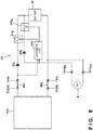
FIG. 8 is a diagram for describing a configuration example of the battery unit. - Hereinafter, embodiments of the present invention will be described with reference to the attached drawings. Note that each diagram is a schematic diagram showing the structure or configuration of an embodiment, and the size of each shown member does not necessarily reflect an actual size. Additionally, in each diagram, the same reference numerals are given to the same elements, and description of duplicate content in this specification is omitted.
-
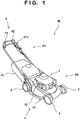
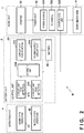
FIG. 1 is a perspective view of a work machine M according to an embodiment.FIG. 2 is a block diagram showing the main part of the configuration of the work machine M. The work machine M includes awork unit 1, a runningunit 2, and abattery unit 3 in a main body unit P0. The work machine M further includes anoperation unit 4 in an extension unit P1 extending behind and upward from the main body unit P0. - In the present embodiment, the
work unit 1 includes awork mechanism 11, apower unit 12, astarter 13, and agrass bag 14. Thework mechanism 11 is a mechanism for achieving a predetermined work. In the present embodiment, thework mechanism 11 is a disc-shaped blade rotatably arranged below the main body unit P0 (refer toFIG. 1 ), and accordingly, grass cutting can be performed as an example of the work (the work machine M may also be called a lawn mower.). - The
power unit 12 includes a source ofpower 121, aflywheel 122, and a charge coil unit 123 (refer toFIG. 2 ). In the present embodiment, the source ofpower 121 is an internal combustion engine (engine), and generates power (rotation) for driving thework mechanism 11. Theflywheel 122 is arranged to be able to rotate according to the power of the source ofpower 121, and stabilizes the rotation by the source ofpower 121. In the present embodiment, theflywheel 122 is coupled to a crankshaft of the internal combustion engine as the source ofpower 121. Theflywheel 122 supports a magnet, which is not shown, and forms a flux change by rotating with this magnet. Although details will be described later, thecharge coil unit 123 is configured to be able to output a voltage according to this flux change. - Further, a transmission such as an HST (Hydro-Static Transmission) may be additionally provided as a part of the
power unit 12 / for thepower unit 12. - The
starter 13 starts thepower unit 12 in response to a signal from acontrol unit 31, which will be described later, included in the battery unit 3 (refer toFIG. 2 ). For example, thestarter 13 is arranged such that a pinion gear is engaged with a ring gear of theflywheel 122, and makes it possible to start thepower unit 12 by rotating the pinion gear. Note that, although details will be described later, thecontrol unit 31 can detect that thepower unit 12 is started, based on the output voltage from the above-describedcharge coil unit 123. - The
grass bag 14 is a containing part for containing grass mown by thework mechanism 11, and is detachably arranged on a rear part of the main body unit P0 (refer toFIG. 1 ). With such a configuration, thework unit 1 can perform the work for a predetermined work area. - The running
unit 2 includes a pair of front wheels and a pair of rear wheels that are each rotatably arranged on a lower part of the main body unit P0, thereby supporting the main body unit P0 (refer toFIG. 1 ). The runningunit 2 can make the work machine M run by receiving the power from thepower unit 12. An end of the extension unit P1 is configured into a bar shape as a grip portion (handle bar) P11 (refer toFIG. 1 ), and the user can perform the work while gripping this grip portion P11 and pressing the work machine M. The work machine M may also be called a walking-type work machine, a walking-type lawn mower, etc. - The
operation unit 4 receives an input operation from the user for controlling the operation state of thework unit 1. Theoperation unit 4 may be provided in a position that is easy for the user to operate. In the present embodiment, theoperation unit 4 includes a lever-type operator 41 and a button-type operator 42, and each of these is arranged in the extension unit P1, particularly the grip portion P11 or its periphery (refer toFIG. 1 ). The lever-type operator 41 is rotatably arranged in parallel to the above-described bar-shape grip portion P11 in the present embodiment, and the user inputs an operation by rotating this lever-type operator 41. The button-type operator 42 is an automatic return type push button switch arranged in one end of the grip portion P11 in the present embodiment, and the user inputs an operation by pressing this button-type operator 42. Note that the input operation by the user to theoperation unit 4 is transmitted to thecontrol unit 31, which will be described later, included in thebattery unit 3 as an electric signal via a cable, a wire, or the like. - In the present embodiment, it is assumed that the
work unit 1 will be in the operation state when the user operates the button-type operator 42 while operating the lever-type operator 41. That is, even if the user presses the button-type operator 42 without rotating the lever-type operator 41, thework unit 11 will not be in the operation state. The above-described operation mode of operating the button-type operator 42 while operating the lever-type operator 41 is also called a two-step operation or the like, and is advantageous for securing the safety at the time of operating thework unit 1. - After the
work unit 1 is in the operation state, the user can perform the work with thework unit 1 in the operation state, by making the work machine M run while maintaining the lever-type operator 41 in an operated state (a state in which the lever-type operator 41 is rotated). Additionally, the user can turn thework unit 1 into a stop state at a desired timing by canceling the operation of the lever-type operator 41 (for example, removing the hands from the lever-type operator 41). In the present embodiment, it is assumed that, in the stop state of thework unit 1, thepower unit 12 will be in a stop state and thework mechanism 11 will also be in a stop state. - As another embodiment, the
work mechanism 11 and thepower unit 12 can be mechanically coupled by a clutch, and the coupling/decoupling of this clutch may be controllable by the lever-type operator 41. For example, the clutch will be in a coupled state by operating the lever-type operator 41, and the clutch will be in a disconnected state by canceling the operation. In this case, in response to cancellation of the above-described operation of the lever-type operator 41, without stopping thepower unit 12, the transmission of its power to thework mechanism 11 can be cut off. - The
operation unit 4 may further include other operators in the extension unit P1 or the main body unit P0. An operator for adjusting the height of the disc-shaped blade, which is thework mechanism 11, an operator for changing the output level of thepower unit 12, an operator for braking the runningunit 2, and the like can be listed as the examples. - The
battery unit 3 includes abattery 30 and thecontrol unit 31, and these are formed into a unit in the present embodiment. Since thebattery 30 and thecontrol unit 31 are formed into the unit, the handling of the battery unit 3 (for example, handling in a case where thebattery unit 3 is assembled to the main body unit P0, and the like) becomes easy. Although thesingle battery 30 is shown here for simplification of the description, the number of thebattery 30 may be two or more. For example, thebattery unit 3 may be configured to contain both a plurality ofbatteries 30 connected inseries 30 and thecontrol unit 31 in a predetermined housing. - The
control unit 31 is an electrical component that receives electric power from thebattery 30, and performs control of each element of the work machine M, for example, the drive control of the above-describedwork unit 1 and the like, based on an input operation by the user to theoperation unit 4. Thecontrol unit 31 may also be called a control device, a control board, or the like, and may include, for example, a wiring unit for achieving electric connection between elements, in addition to one or more mounting substrates on which electronic components are mounted. As examples of the electronic components, semiconductor devices, such as an ASIC (application specific semiconductor integrated circuit), a PLD (programmable logic device), and a so-called discrete component, can be listed. As examples of the wiring unit, a wire harness, an FPC (flexible printed circuit), a CoF (chip on film), and the like can be listed. - In the present embodiment, the
control unit 31 includes an arithmetic unit (signalprocessing circuit unit) 310,circuit units circuit unit 313 for starting, and a power supply circuit unit 314 (refer toFIG. 2 ). Note that, in the present specification, a circuit unit refers to an element in which one or more passive elements or active elements are electrically connected so that a predetermined function can be achieved, and thus, each of the circuit units may be separately provided in several portions, or may be provided in the vicinity of other circuit unit. - The
arithmetic unit 310 is an MCU (Micro Controller Unit) or MPU (Micro Processing Unit) that performs signal processing for performing system control of the entire work machine M based on the electric power of thebattery 30. A predetermined battery management IC (Integrated Circuit), such as RAJ240100 (Renesas Electronics Corporation), may be used for thearithmetic unit 310. - One or more input circuit ICs capable of detecting an operation that is input to the lever-
type operator 41 may be used for thecircuit unit 311 for detection. Thecircuit unit 311 for detection supplies, to thearithmetic unit 310, an electric signal indicating that an operation is input to the lever-type operator 41. - One or more input circuit ICs capable of detecting an operation that is input to the button-
type operator 42 may be used for thecircuit unit 312 for detection. Thecircuit unit 312 for detection supplies, to thearithmetic unit 310, an electric signal indicating that an operation is input to the lever-type operator 42. - In response to receiving the signals from both of the
circuit units arithmetic unit 310 outputs a predetermined start signal to thecircuit unit 313 for starting, and starts thepower unit 12 by using thestarter 13. The power of thepower unit 12 is transmitted to thework mechanism 11, and thework mechanism 11 will be in a drive state, that is, thework unit 1 will be in the operation state. - The power
supply circuit unit 314 generates one or more power supply voltages based on the voltage of thebattery 30, and supplies it/them to thearithmetic unit 310. The powersupply circuit unit 314 may be provided to be able to divide the voltage of thebattery 30 with a predetermined voltage divider circuit, or as an alternative to this, a power supply IC including a DC-DC converter and the like may be used as the powersupply circuit unit 314. Although the expression voltage (power supply voltage) is used here for simplification of the description, the expression electric power may be used in consideration of a current component, such as a drive current. Note that thearithmetic unit 310 includes a built-in regulator, and can also generate yet another power supply voltage based on the power supply voltage received from the powersupply circuit unit 314. - It is assumed that a rechargeable secondary battery, such as a lithium ion battery and a nickel hydride battery, is used for the
battery 30. Here, thecharge coil unit 123 and thecontrol unit 31 are electrically connected to each other, and thecontrol unit 31 can charge thebattery 30 based on the output voltage from thecharge coil unit 123. This will be described below with reference toFIG. 3 to FIG. 4B3 . -
FIG. 3 is a diagram for describing a configuration example of thecharge coil unit 123. Thecharge coil unit 123 is electrically connected to thecontrol unit 31 viapredetermined wiring units - The
charge coil unit 123 includes an inductor L1, a capacitor C1, and acircuit unit 1231. The inductor L1 and the capacitor C1 are mutually connected in series. In the present embodiment, the inductor L1 is arranged on a low voltage side (ground side), and the capacitor C1 is arranged on a high voltage side (power supply voltage side). Thecircuit unit 1231 is provided to be able to charge the capacitor C1 by an induced current generated in the inductor L1. In the present embodiment, thecircuit unit 1231 includes rectifier elements D1 and D2, the rectifier element D1 is connected in parallel to the capacitor C1, and the rectifier element D2 is connected in parallel to the above-described inductor L and capacitor C1 that are connected in series. The rectifier element D2 is configured such that its breakdown voltage becomes lower than the breakdown voltage of the rectifier element D1, and in the present embodiment, it is assumed that a Zener diode is used as the rectifier element D2. - Note that the
circuit unit 1231 may further include a resistance element having a relatively high resistance value (a pull-up resistance element or a pull-down resistance element) for the purpose of giving an initial potential to a node between the inductor L and the capacitor C1, or the like. Additionally, the inductance of the inductor L and the capacitance of the capacitor C1 may be determined based on the design values of respective elements, such as the maximum output value of the source ofpower 121, and battery capacity of thebattery 30. - The
charge coil unit 123 further includes a connection terminal T123H on the high voltage side and a connection terminal T123L on the low voltage as external electrodes for achieving electric connection with thecontrol unit 31. Thecontrol unit 31 further includes a connection terminal T31H on the high voltage side and a connection terminal T31L on the low voltage side as external electrodes for achieving electric connection with thecharge coil unit 123. The connection terminal T123H and the connection terminal T31H are connected by thewiring unit 901, and the connection terminal T123L and the connection terminal T31L are connected by thewiring unit 902, and accordingly, thecharge coil unit 123 is electrically connected to thecontrol unit 31. - The
control unit 31 further includes aswitching unit 315 and a rectifier element D3. Theswitching unit 315 is, for example, an electronic component including a high breakdown voltage transistor, and can switch between start and end of the charging operation at the time of charging thebattery 30. For example, when theswitching unit 315 is turned into a conductive state, charging of thebattery 30 is performed, and when theswitching unit 315 is turned into a non-conductive state, charging of thebattery 30 is stopped. The rectifier element D3 is an electronic component for preventing the reverse current flow from thebattery 30 to thecharge coil unit 123 at the time of performing charging of thebattery 30, and can protect thecharge coil unit 123. Theswitching unit 315 and the rectifier element D3 may be mounted on a predetermined mounting substrate with thearithmetic unit 310. - As shown in
FIG. 3 , theswitching unit 315 and the rectifier element D3 are connected in series between the connection terminal T31H and the positive terminal (+) of thebattery 30. In the present embodiment, theswitching unit 315 is arranged on a positive terminal side of thebattery 30, and the rectifier element D3 is arranged on a connection terminal T31H side. In the present embodiment, thearithmetic unit 310 is arranged to be able to switch between the conductive state and the non-conductive state of theswitching unit 315 based on the output voltage (the voltage value or signal level of the connection terminal T31H) from thecharge coil unit 123. Additionally, the negative terminal (-) of thebattery 30 is connected to the connection terminal T31L. -
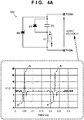
FIG. 4A is a diagram for describing an operation mode of thecharge coil unit 123. As previously described, the magnet is supported by theflywheel 122, and the flux change is generated by the magnet in association with the power of the source of power 121 (the rotation of the flywheel 122). In the present embodiment, it is assumed that (the strength of) a magnetic field changes in a sinusoidal manner with the rotation of theflywheel 122, and one period of the change in the magnetic field corresponds to one rotation of theflywheel 122. - The
charge coil unit 123 is arranged in the position where the above-described flux change can be detected, and by this flux change, an induced voltage is generated in the inductor L1 in the direction indicated by "a" or "b" in the diagram. Although details will be described later, for example, when the induced voltage in the above-described a direction is generated, the current (induced current) generated by this induced voltage is led to the capacitor C1 by the rectifier element D2, and charges the capacitor C1. - The waveform of an output voltage V1 (open circuit voltage) of the
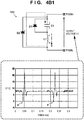
charge coil unit 123 is also shown in the lower part ofFIG. 4A . In the present embodiment, the charging voltage (here, approximately 8 [V]) of the capacitor C1 biases the output voltage V1, and the output voltage V1 shows a pulsed waveform according to the generation of the above-described induced voltage while using approximately 8 [V] as a reference point.FIG. 4B1 shows a mode in a case where the induced voltage in the above-described a direction is generated as inFIG. 4A .FIG. 4B2 shows a mode in a case where the induced voltage in the above-described b direction is generated as inFIG. 4A .FIG. 4B3 shows a mode in a case where the induced voltage in the above-described a direction is generated again (the second time) as inFIG. 4A (indicated by "a'", so as to distinguish from the induced voltage in the above-described a direction in the first time.). - As shown in
FIG. 4B1 , when the induced voltage in the above-described a direction is generated, the charging current for the capacitor C1 is generated, and the capacitor C1 is charged. In the figure, this charging current is indicated by a broken line arrow. Additionally, in the figure, the generation direction (polarity) of the induced voltage of the inductor L1 is indicated by "+" and "-". When enough time has passed since the rotation of theflywheel 122 is started, in the present embodiment, the charging voltage of the capacitor C1 associated with the generation of the induced voltage in the above-described a direction is approximately 8 [V]. In the figure, similar to the induced voltage of the inductor L1, the generation direction (polarity) of the charging voltage of the capacitor C1 is indicated by "+" and "-". - Thereafter, as shown in
FIG. 4B2 , when the induced voltage is generated in the above-described b direction, the generation direction of the induced voltage of the inductor L1 and the generation direction of the charging voltage of the capacitor C1 become mutually the same as indicated by "+" and "-" in the figure. The output voltage V1 is the sum of "the induced voltage of the inductor L1" and "the charging voltage of the capacitor C1", and accordingly, the output voltage V1 is increased to approximately 22 [V]. - Further, thereafter, as shown in
FIG. 4B3 , the induced voltage in the above-described a' direction is generated. The induced voltage in the above-described a' direction is approximately 3 [V], and is lower than the induced voltage (approximately 8 [V]) generated earlier. Therefore, a current in the forward direction does not substantially flow into the diode D2, that is, the charging current to the capacitor C1 is not substantially generated. When the induced voltage in the above-described a' direction is generated, as in the case where the induced voltage in the above-described b direction is generated, the output voltage V1 is the sum of "the induced voltage of the inductor L1" and "the charging voltage of the capacitor C1", and the output voltage V1 returns to approximately 8 [V] after being decreased to approximately 5 [V]. - As previously described, the Zener diode is used for the rectifier element D2, and the
charge coil unit 123 may be configured such that the output voltage V1 does not exceed the breakdown voltage of the rectifier element D2. The breakdown voltage of the rectifier element D2 may be about 150 [V], or may be about 100 [V] or 50 [V]. Accordingly, it is ensured that no overvoltage is applied to the output target of thecharge coil unit 123, and in the present embodiment, thebattery 30 and thecontrol unit 31 can be protected. - With such a circuit configuration, the
charge coil unit 123 outputs a signal based on the power of the source ofpower 121 to thecontrol unit 31 as the output voltage V1. In thecontrol unit 31, thearithmetic unit 310 controls theswitching unit 315 based on the output voltage V1. For example, when theswitching unit 315 is in the conductive state, thecontrol unit 31 can charge thebattery 30 by using the output voltage V1. At this time, in the present circuit configuration, since the output voltage V1 is biased by the charging voltage (approximately 8 [V]) of the capacitor C1, it is also advantageous for faster charging of thebattery 30. In addition, thecontrol unit 31 can also additionally perform detection of the number of rotations of the source ofpower 121, and other control using the detection result. -
FIG. 5 is a diagram for describing an operation mode of thecharge coil unit 123R as a comparison example. In the comparison example, thecharge coil unit 123R includes the inductor L1 and the capacitor C1 mutually connected in parallel, and the rectifier element D1 connected to them in series. - In the circuit configuration of the comparison example, the current flowing into the capacitor C1 is in the opposite direction between the case where the induced voltage is generated in the direction indicated by "a" in the figure, and the case where the induced voltage is generated in the direction indicated by "b" in the figure. That is, in the case of the circuit configuration of the comparison example, charging and discharging of the capacitor C1 will be repeated alternately. Therefore, the voltage of the capacitor C1 remains approximately 0 [V]. Additionally, in the circuit configuration of the comparison example, since a closed loop path that allows a current to flow bidirectionally is formed by the inductor L1 and the capacitor C1, the so-called LC oscillation may occur. Therefore, as indicated by a portion K, an output voltage V2 of the
charge coil unit 123R will show a plurality of pulsed waveforms with approximately 0 [V] as the reference point, for one period of the change in the magnetic field (one rotation of the flywheel 122). - Thus, according to the comparison example, it is difficult for the
control unit 31 to control theswitching unit 315 based on the output voltage V2, and to effectively perform charging of thebattery 30. In addition, for the same reason, it is also difficult for thecontrol unit 31 to perform detection of the number of rotations of the source ofpower 121, and other control using the detection result. Further, since the rectifier element D2 that can act as a protective element, such as a Zener diode, is not provided in thecharge coil unit 123R, the output voltage V2 that has become an overvoltage may be applied to the output targets, such as thebattery 30 and thecontrol unit 31. - On the other hand, according to the present embodiment (
FIG. 4A and the like), in the closed loop path formed by the inductor L1 and the capacitor C1, since the current in one direction will be allowed and the current in the other direction will be limited by the rectifier elements D1 and D2, the LC oscillation is appropriately regulated or suppressed. Therefore, according to the present embodiment, the output voltage V1 of thecharge coil unit 123 is stabilized, and shows a substantially single pulsed waveform with approximately 8 [V] as the reference point. Thus, according to the present embodiment, thecontrol unit 31 can appropriately control theswitching unit 315 based on the output voltage V2, and can effectively perform charging of thebattery 30. In addition, according to the present embodiment, since the rectifier element D2 is provided such that its breakdown voltage becomes relatively low, and the output voltage V1 does not become an overvoltage, unexpected overvoltage is not applied to the output targets, such as thebattery 30 and thecontrol unit 31. - Additionally, in the present embodiment, the direction of the current at the time of charging of the capacitor C1 is determined in one direction, and the direction of the current at the time of discharging of the capacitor C1 is also determined in one direction. From another viewpoint, it can also be said that one terminal of the two terminals of the capacitor C1, in which charging and discharging are performed, is statically determined. Therefore, according to the present embodiment, a polarized capacitor such as an electrolytic capacitor, that is, an electronic component including two terminals, i.e., a positive terminal and a negative terminal, can be used for the capacitor C1. Therefore, compared with a case where a non-polarized capacitor such as a ceramic capacitor, that is, an electronic component with no distinction between a positive terminal and a negative terminal, is used, it may be possible to reduce the cost of the
charge coil unit 123. - Additionally, in the present embodiment, a circuit configuration is used in which the inductor L1 is arranged on the low voltage side, and the capacitor C1 is arranged on the high voltage side. Therefore, the charging voltage of the capacitor C1 biases the output voltage V1, and here, the output voltage V1 is offset by approximately 8 [V] (refer to
FIG. 4A and the like). Therefore, in a case where the battery is charged by using this output voltage V1, it becomes possible to accelerate the charging. - The circuit configuration that can stabilize the output voltage V1 is not limited to the above-described examples, and can be modified within a range that does not deviate from the spirit of the present invention. For example, in the circuit configuration exemplified in
FIG. 4A , thecircuit unit 1231 is provided to be able to charge the capacitor C1 by the induced current irrespective of the direction of the induced current generated in the inductor L1. However, the configuration of thecircuit unit 1231 may be partially changed such that charging of the capacitor C1 is enabled when the induced current in one direction is generated in the inductor L1, and discharging of the capacitor C1 is limited when the induced current in the other direction is generated in the inductor L1. -
FIG. 6 shows a circuit configuration example of a charge coil unit 123' as another embodiment. The charge coil unit 123' includes a circuit unit 1231', instead of thecircuit unit 1231. The circuit unit 1231' includes the rectifier element D2 connected in parallel to the inductor L1 and the capacitor C1 that are mutually connected in series, that is, the rectifier element D1 is omitted from the circuit configuration inFIG. 4A . According to such a circuit configuration, in the closed loop path formed by the inductor L1 and the capacitor C1, the current in one direction will be allowed, and the current in the other direction will be limited. Therefore, also in the charge coil unit 123' exemplified inFIG. 6 , repeated charging and discharging of the capacitor C1 and the LC oscillation are regulated or suppressed, and accordingly, the output voltage V1' of the charge coil unit 123' can be stabilized. - According to the above embodiments, the
charge coil unit 123 or 123' includes the inductor L1 and the capacitor C1 mutually connected in series, and thecircuit unit 1231 or 1231'. Thecircuit unit 1231 or 1231' is provided to be able to charge the capacitor C1 by the induced current generated in the inductor L1. According to such a circuit configuration, the signal based on the power of the source ofpower 121 can be stably output as the output voltage V1. The power of the source ofpower 121 can be detected based on this output voltage V1, and in the present embodiment, since one rotation of theflywheel 122 corresponds to one pulse of the output voltage V1, the number of rotations of the source ofpower 121 can be appropriately detected. - Incidentally, in the present embodiment, the
battery 30 and thecontrol unit 31 are formed into the unit (that is, thebattery 30 and thecontrol unit 31 are integrally provided) to form thebattery unit 3. Thus, according to the present embodiment, assembly of thebattery unit 3 is simplified at the time of manufacturing of the work machine M, and it can be said that it is also advantageous for preparation of thebattery unit 3. - On the other hand, since the frequency with which the work machine M is used is often varied through the season, and the user may not use the work machine M over a relatively long period of time, it is also conceivable that so-called battery down may occur. As a countermeasure against this battery down, it is also conceivable to remove the
battery 30 from the work machine M in advance. However, attachment and detachment of thebattery 30 are complicated for a user in many cases, and particularly, in the present embodiment, thebattery 30 is formed into the unit with thecontrol unit 31 as thebattery unit 3. Therefore, this may also become the cause of increasing the user's burden. Additionally, in the configuration inFIG. 2 , when the above-described battery down occurs, since thecontrol unit 31 cannot receive electric power from thebattery 30, thecontrol unit 31 cannot start thepower unit 12 via thestarter 13. Thus, other element that can charge thebattery 30 may be further provided in thecontrol unit 31. This will be described in detail below with reference toFIG. 7 andFIG. 8 . -
FIG. 7 shows, as a first example, thecontrol unit 31 that is electrically connected to thecharge coil unit 123, and that further includes other element that can charge thebattery 30. Although a detailed configuration is not shown here, thecharge coil unit 123 may be similarly configured as inFIG. 3 . Thecontrol unit 31 further includes a connection terminal T31HEX on the high voltage side, and a connection terminal T31LEX on the low voltage side, as external electrodes for achieving electric connection to theexternal power supply 8. In addition, thecontrol unit 31 further includes a rectifier element D4. - In the first example, the connection terminal T31HEX is connected to an electric path between the switching
unit 315 and the rectifier element D3, and thearithmetic unit 310 can receive the voltage value or signal level of this connection terminal T31HEX. In addition, the connection terminal T31LEX is connected to an electric path between the negative terminal of thebattery 30 and the connection terminal T31L. - It is assumed that the
external power supply 8 is a power source that is not electrically connected in normal time, and is externally added when necessary in emergency. Normal time here refers to a case where thework unit 1 can be operated, that is, a case where the above-described battery down has not occurred, and the concept of normal time includes working time and non-working time in which working can be started, and the other time is assumed to be emergency. A predetermined power source that can be connected to the above-described connection terminals T31HEX and T31LEX, or that conforms to their standards may be used for theexternal power supply 8. - According to the first example, when the above-described battery down occurs, the
external power supply 8 can be electrically connected to the above-described connection terminals T31HEx and T31LEX. When theexternal power supply 8 is electrically connected, thearithmetic unit 310 detects that based on the voltage value or signal level of the connection terminal T31HEX, and controls theswitching unit 315 in response to the detection. In this manner, thecontrol unit 31 can control the charging operation of thebattery 30 using theexternal power supply 8. - Here, when the above-described
external power supply 8 is electrically connected, the current toward thecharge coil unit 123 from thisexternal power supply 8, that is, the reverse current flow to thepower unit 12 from theexternal power supply 8, is prevented by the rectifier element D3. Accordingly, thepower unit 12, mainly thecharge coil unit 123, can be protected, and both thebattery 30 and theexternal power supply 8 can be protected from the unexpected output voltage of thecharge coil unit 123 that can be generated when the above-described reverse current flow is generated. - In addition, the rectifier element D4 is arranged so as to prevent the reverse current flow from the
charge coil unit 123 and thebattery 30 to theexternal power supply 8 when the above-describedexternal power supply 8 is electrically connected, and accordingly, theexternal power supply 8 can be protected. - According to the above-described the first example, the
power unit 12 can be turned into the operation state in normal time, and the electric power from the power unit 12 (the output voltage from the charge coil unit 123) is input to the connection terminal T31H as the charging power of thebattery 30. Additionally, in emergency, theexternal power supply 8 can be electrically connected, and the electric power from the electrically connectedexternal power supply 8 is input to the connection terminal T31HEX as the charging power of thebattery 30. Thecontrol unit 31 can receive these electric powers from the connection terminals T31H and T31HEX, respectively, and can appropriately perform the charging operation of thebattery 30 by using these electric powers. In addition, when theexternal power supply 8 is electrically connected, thepower unit 12 can be protected, and along with this, thebattery 30 and theexternal power supply 8 can also be protected. - As mentioned above, according to the first example, the
work unit 31 functions as a control device for controlling the charging operation of thebattery 30. Thework unit 31 includes the connection terminals T31H and T31HEX, and the rectifier element D3. The connection terminal T31H corresponds to the electrode that receives the electric power from thepower unit 12 as the charging power of thebattery 30. The connection terminal T31HEX is provided to be able to be electrically connected to theexternal power supply 8 in emergency, and corresponds to the electrode that can receive the electric power from the electrically connectedexternal power supply 8 as the charging power of thebattery 30. The rectifier element D3 is arranged in an electric path between both thebattery 30 and the electrode T31HEX and the electrode T31H, allows passage of the electric power from thepower unit 12 to thebattery 30, and regulates passage of the electric power from theexternal power supply 8 to thepower unit 12. - According to the above-described configuration, in normal time, the charging operation of the
battery 30 based on the electric power from thepower unit 12 is enabled, and in emergency, by electrically connecting theexternal power supply 8, the charging operation of thebattery 30 based on the electric power of theexternal power supply 8 is enabled. Accordingly, the charging operation of thebattery 30 can be appropriately controlled. In addition, according to the above-described configuration, when theexternal power supply 8 is electrically connected, thepower unit 12 can be protected by preventing the reverse current flow from theexternal power supply 8 to thepower unit 12, and along with this, thebattery 30 and theexternal power supply 8 can be protected. -
FIG. 8 shows, as a second example, thecontrol unit 31 further including a yet another configuration that can charge thebattery 30. Thecharge coil unit 123 may be similarly configured as inFIG. 3 . In the second example, thecontrol unit 31 further includes asecond switching unit 3152 and a second rectifier element D32. For distinction, let theaforementioned switching unit 315 be "thefirst switching unit 3151", and let the aforementioned rectifier element D3 be "the first rectifier element D31." Note that the rectifier element D4 is omitted in the second example. - The
switching unit 3152 and the rectifier element D32 are connected in series between the connection terminal T31HEX and the positive terminal of thebattery 30. Theswitching unit 3152 is arranged on the positive terminal side of thebattery 30, and the rectifier element D32 is arranged on a connection terminal T31HEX side. That is, theswitching unit 3151 and theswitching unit 3152 are mutually connected in parallel to thebattery 30. Additionally, the rectifier element D31 is arranged in an electric path between the connection terminal T31H and theswitching unit 3151, and the rectifier element D32 is arranged in an electric path between the connection terminal T31HEX and theswitching unit 3152. When theexternal power supply 8 is electrically connected, thearithmetic unit 310 detects that based on the voltage value or signal level of the connection terminal T31HEX, and controls theswitching unit 3152 in response to the detection. In this manner, thecontrol unit 31 can control the charging operation of thebattery 30 using theexternal power supply 8. - Also by the above-described the second example, as in the first example, the
control unit 31 can appropriately perform the charging operation of thebattery 30 by using the electric power from thepower unit 12 and the electric power from theexternal power supply 8. In addition, since thearithmetic unit 310 can individually control theswitching unit 3151 and theswitching unit 3152 based on the voltage values or signal levels of the connection terminals T31H and T31HEX, it becomes possible to make the configuration relatively simple. Thus, according to the above-described second example, the same effect as in the first example can be obtained, and it can also be said that it is advantageous for reducing the cost of thecontrol unit 31. - The embodiments are summarized below:
A first aspect relates to a control device (for example, 31), and the control device is a control device for controlling a charging operation of a battery (for example, 30), and includes a first electrode (for example, T31H) that is electrically connected to a power unit (for example, 12), and that receives a first electric power from the power unit as charging power of the battery, a second electrode (for example, T31HEX) that is provided to be able to be electrically connected to a predetermined power source (for example, 8), and that can receive a second electric power from the predetermined power source as the charging power of the battery, and a rectifier element (for example, D3, D31) that is arranged in an electric path between both the battery and the second electrode and the first electrode, so as to allow passage of the first electric power from the power unit to the battery, and to regulate passage of the second electric power from the predetermined power source electrically connected to the second electrode to the power unit. - According to the first aspect, the charging operation of the battery based on the above-described first to second electric powers can be appropriately controlled. In addition, when the predetermined power source is electrically connected, the power unit, the battery, and the external power supply can be protected by preventing the reverse current flow to the power unit, and it can also be said that it is advantageous for improving reliability.
- In a second aspect, a switching unit (for example, 315) for switching between start and end of the charging operation and connected to the battery is further included, and the rectifier element is arranged in an electric path between the switching unit and the first electrode.
- According to the second aspect, the above-described first aspect can be achieved with a relatively simple configuration.
- In a third aspect, the rectifier element is a first rectifier element (for example, D31), and the control device further includes a first switching unit (for example, 3151) for switching between start and end of the charging operation by the first electric power, a second switching unit (for example, 3152) for switching between start and end of the charging operation by the second electric power, and a second rectifier element (for example, D32), the first switching unit and the second switching unit are mutually connected in parallel to the battery, the first rectifier element is arranged in an electric path between the first electrode and the first switching unit, and the second rectifier element is arranged in an electric path between the second electrode and the second switching unit.
- According to the third aspect, the above-described first aspect can be achieved with a relatively simple configuration.
- A fourth aspect relates to a battery unit (for example, 3), and the battery unit integrally includes the above-described control device (for example, 31) and the battery (for example, 30).
- According to the fourth aspect, handling of the battery unit becomes easy by forming the above-described control device and battery into a unit.
- A fifth aspect relates to a work machine (for example, M), and the work machine is a work machine including a work unit (for example, 1) for performing work, and includes the battery unit (for example, 3) described above and the power unit (for example, 12).
- According to the fifth aspect, the above-described battery unit can be applied to a common work machine with the power unit.
- In a sixth aspect, the power unit includes a source of power (for example, 121) for operating the work unit, a flywheel (for example, 122) that supports a magnet and that is arranged to be able to rotate according to the power of the source of power, and a charge coil unit (for example, 123) that is supported by the flywheel so as to be able to output a voltage based on the power of the source of power as the first electric power.
- According to the sixth aspect, the battery in the above-described battery unit can be relatively simply charged.
- In a seventh aspect, the charge coil unit includes an inductor (for example, L1) that generates an induced current based on the power of the source of power, a capacitor (for example, C1) connected in series to the inductor, and a circuit unit (for example, 1231) provided to be able to charge the capacitor by the induced current generated in the inductor.
- According to the seventh aspect, the charge coil unit can stably output a signal based on the power of the source of power as the output voltage, and the battery in the above-described battery unit can be appropriately charged.
- The present invention is not limited to the above embodiments and various changes and modifications can be made within the spirit and scope of the present invention. Therefore, to apprise the public of the scope of the present invention, the following claims are made.
Claims (7)
- A control device for controlling a charging operation of a battery, the control device characterized by comprising:a first electrode that is electrically connected to a power unit, and that receives a first electric power from the power unit as charging power of the battery;a second electrode that is provided to be able to be electrically connected to a predetermined power source, and that can receive a second electric power from the predetermined power source as the charging power of the battery; anda rectifier element that is arranged in an electric path between both the battery and the second electrode and the first electrode, so as to allow passage of the first electric power from the power unit to the battery, and to regulate passage of the second electric power from the predetermined power source electrically connected to the second electrode to the power unit.
- The control device according to claim 1, characterized by further comprising:a switching unit for switching between start and end of the charging operation and connected to the battery,wherein the rectifier element is arranged in an electric path between the switching unit and the first electrode.
- The control device according to claim 1, characterized in that:the rectifier element is a first rectifier element,the control device further comprises a first switching unit for switching between start and end of the charging operation by the first electric power, a second switching unit for switching between start and end of the charging operation by the second electric power, and a second rectifier element,the first switching unit and the second switching unit are mutually connected in parallel to the battery, andthe first rectifier element is arranged in an electric path between the first electrode and the first switching unit, and the second rectifier element is arranged in an electric path between the second electrode and the second switching unit.
- A battery unit characterized by integrally comprising the control device according to any one of claims 1 to 3, and the battery.
- A work machine including a work unit for performing work, the work machine characterized by comprising:the battery unit according to claim 4; andthe power unit.
- The work machine according to claim 5, characterized in that the power unit comprises:a source of power for operating the work unit;a flywheel that supports a magnet, and that is arranged to be able to rotate according to power of the source of power; anda charge coil unit that is supported by the flywheel so as to be able to output a voltage based on the power of the source of power as the first electric power.
- The work machine according to claim 6, characterized in that:
the charge coil unit comprises an inductor that generates an induced current based on the power of the source of power, a capacitor connected in series to the inductor, and a circuit unit provided to be able to charge the capacitor by the induced current generated in the inductor.
Applications Claiming Priority (1)
| Application Number | Priority Date | Filing Date | Title |
|---|---|---|---|
| PCT/JP2018/035694 WO2020065768A1 (en) | 2018-09-26 | 2018-09-26 | Control device, battery unit, and work machine |
Publications (3)
| Publication Number | Publication Date |
|---|---|
| EP3843232A1 true EP3843232A1 (en) | 2021-06-30 |
| EP3843232A4 EP3843232A4 (en) | 2021-08-25 |
| EP3843232B1 EP3843232B1 (en) | 2022-10-26 |
Family
ID=69950378
Family Applications (1)
| Application Number | Title | Priority Date | Filing Date |
|---|---|---|---|
| EP18935565.4A Active EP3843232B1 (en) | 2018-09-26 | 2018-09-26 | Control device, battery unit, and work machine |
Country Status (5)
| Country | Link |
|---|---|
| US (1) | US12027902B2 (en) |
| EP (1) | EP3843232B1 (en) |
| CN (1) | CN112771750B (en) |
| AU (1) | AU2018443944B2 (en) |
| WO (1) | WO2020065768A1 (en) |
Families Citing this family (1)
| Publication number | Priority date | Publication date | Assignee | Title |
|---|---|---|---|---|
| AU2018443944B2 (en) | 2018-09-26 | 2022-10-27 | Honda Motor Company., Ltd. | Control device, battery unit, and work machine |
Family Cites Families (17)
| Publication number | Priority date | Publication date | Assignee | Title |
|---|---|---|---|---|
| US4358727A (en) * | 1980-09-25 | 1982-11-09 | Tecumseh Products Company | Economical flywheel alternator for trickle charging a small lawnmower battery |
| US4394893A (en) * | 1980-11-07 | 1983-07-26 | Tecumseh Products Company | Engine shut-off system with flywheel braking |
| JP2527787Y2 (en) * | 1993-07-08 | 1997-03-05 | 日新電機株式会社 | Power supply switching device |
| US5864223A (en) * | 1996-11-05 | 1999-01-26 | Meyer; Dennis R. | Battery life extender apparatus |
| JP3905418B2 (en) * | 2001-05-18 | 2007-04-18 | セイコーインスツル株式会社 | Power supply device and electronic device |
| JP2008182822A (en) * | 2007-01-24 | 2008-08-07 | Matsushita Electric Ind Co Ltd | Charger |
| WO2010103603A1 (en) * | 2009-03-09 | 2010-09-16 | 富士通株式会社 | Circuit for switching type of operating power source |
| JP5234052B2 (en) * | 2010-04-27 | 2013-07-10 | 株式会社デンソー | Power supply |
| JP2011234573A (en) * | 2010-04-28 | 2011-11-17 | Toshiba Corp | Information processor and method for controlling the same |
| EP2735077B1 (en) | 2011-07-24 | 2017-06-21 | Makita Corporation | Portable battery pack charging system and method for recharging a battery pack |
| US9127658B2 (en) | 2011-11-04 | 2015-09-08 | Briggs & Stratton Corporation | Internal combustion engine including starting system powered by lithium-ion battery |
| JP2013102573A (en) * | 2011-11-07 | 2013-05-23 | Sony Corp | Charge/discharge controlling apparatus and charge/discharge controlling system |
| US10685299B2 (en) | 2012-03-08 | 2020-06-16 | Husqvarna Ab | Engine speed data usage system and method |
| JP2015126515A (en) * | 2013-12-27 | 2015-07-06 | キヤノン株式会社 | Electronics |
| US9898060B2 (en) * | 2014-09-16 | 2018-02-20 | Integrated Device Technology, Inc. | System and method for wireless power transfer using automatic power supply selection |
| US20160204623A1 (en) * | 2015-01-08 | 2016-07-14 | Hand Held Products, Inc. | Charge limit selection for variable power supply configuration |
| AU2018443944B2 (en) | 2018-09-26 | 2022-10-27 | Honda Motor Company., Ltd. | Control device, battery unit, and work machine |
-
2018
- 2018-09-26 AU AU2018443944A patent/AU2018443944B2/en not_active Ceased
- 2018-09-26 CN CN201880098015.2A patent/CN112771750B/en active Active
- 2018-09-26 WO PCT/JP2018/035694 patent/WO2020065768A1/en not_active Ceased
- 2018-09-26 EP EP18935565.4A patent/EP3843232B1/en active Active
-
2021
- 2021-03-19 US US17/206,569 patent/US12027902B2/en active Active
Also Published As
| Publication number | Publication date |
|---|---|
| US12027902B2 (en) | 2024-07-02 |
| EP3843232A4 (en) | 2021-08-25 |
| EP3843232B1 (en) | 2022-10-26 |
| CN112771750B (en) | 2024-06-07 |
| WO2020065768A1 (en) | 2020-04-02 |
| CN112771750A (en) | 2021-05-07 |
| US20210210960A1 (en) | 2021-07-08 |
| AU2018443944A1 (en) | 2021-04-29 |
| AU2018443944B2 (en) | 2022-10-27 |
Similar Documents
| Publication | Publication Date | Title |
|---|---|---|
| EP3008803B1 (en) | Charging method and hand-held device for mobile small-scale electrical device | |
| US10199831B2 (en) | Circuit arrangement for inline voltage supply, use of such a circuit arrangement and device having such a circuit arrangement | |
| US8199449B2 (en) | Method and a device for monitoring high-voltage connections of a hybrid vehicle | |
| CN101814725B (en) | Secondary battery | |
| EP2413429A2 (en) | Charging device for vehicle and vehicle | |
| US20060163946A1 (en) | Controller in a vehicle | |
| US20170237276A1 (en) | Circuit device, power receiving device, and electronic apparatus | |
| US10958106B2 (en) | Control device, power transmitting device, contactless power transmission system, power receiving device, and electronic apparatus | |
| JP2005012884A (en) | Charging circuit and charging device using the same | |
| EP2797202A1 (en) | Battery monitoring and control integrated circuit and a battery system | |
| US12027902B2 (en) | Control device, battery unit, and work machine | |
| CN114846709A (en) | Electric processing appliance with energy supply device | |
| US11451082B2 (en) | Charge coil unit, power unit, and work machine | |
| RU2586240C2 (en) | Surgical device with improved network module | |
| US6169378B1 (en) | Electronically commutated motor with galvanically separate user interface circuit | |
| CN211266559U (en) | Constant-current constant-voltage charging circuit and switching power supply | |
| CN211351688U (en) | ACC trigger control's undervoltage protection circuit, two mesh camera devices and autopilot system | |
| GB1585915A (en) | Dual battery charge control | |
| JP7606620B2 (en) | Smart Chargers for Rechargeable Electronic Devices | |
| RU2820297C1 (en) | Smart charger for rechargeable electronic device | |
| CN211790898U (en) | Charging control circuit and charging control device | |
| CN210041404U (en) | Reverse connection prevention charging device and electronic equipment | |
| JP4379464B2 (en) | Electric washing machine | |
| KR0120095Y1 (en) | Backup time compensation circuit | |
| WO2014054380A1 (en) | Charger having power generator |
Legal Events
| Date | Code | Title | Description |
|---|---|---|---|
| STAA | Information on the status of an ep patent application or granted ep patent |
Free format text: STATUS: THE INTERNATIONAL PUBLICATION HAS BEEN MADE |
|
| PUAI | Public reference made under article 153(3) epc to a published international application that has entered the european phase |
Free format text: ORIGINAL CODE: 0009012 |
|
| STAA | Information on the status of an ep patent application or granted ep patent |
Free format text: STATUS: REQUEST FOR EXAMINATION WAS MADE |
|
| 17P | Request for examination filed |
Effective date: 20210325 |
|
| AK | Designated contracting states |
Kind code of ref document: A1 Designated state(s): AL AT BE BG CH CY CZ DE DK EE ES FI FR GB GR HR HU IE IS IT LI LT LU LV MC MK MT NL NO PL PT RO RS SE SI SK SM TR |
|
| A4 | Supplementary search report drawn up and despatched |
Effective date: 20210728 |
|
| RIC1 | Information provided on ipc code assigned before grant |
Ipc: H02J 7/00 20060101AFI20210722BHEP Ipc: H02J 1/00 20060101ALI20210722BHEP Ipc: H02J 1/10 20060101ALI20210722BHEP |
|
| DAV | Request for validation of the european patent (deleted) | ||
| DAX | Request for extension of the european patent (deleted) | ||
| GRAP | Despatch of communication of intention to grant a patent |
Free format text: ORIGINAL CODE: EPIDOSNIGR1 |
|
| STAA | Information on the status of an ep patent application or granted ep patent |
Free format text: STATUS: GRANT OF PATENT IS INTENDED |
|
| RIC1 | Information provided on ipc code assigned before grant |
Ipc: H02J 7/32 20060101ALI20220421BHEP Ipc: H02J 1/10 20060101ALI20220421BHEP Ipc: H02J 1/00 20060101ALI20220421BHEP Ipc: H02J 7/00 20060101AFI20220421BHEP |
|
| INTG | Intention to grant announced |
Effective date: 20220511 |
|
| GRAS | Grant fee paid |
Free format text: ORIGINAL CODE: EPIDOSNIGR3 |
|
| GRAA | (expected) grant |
Free format text: ORIGINAL CODE: 0009210 |
|
| STAA | Information on the status of an ep patent application or granted ep patent |
Free format text: STATUS: THE PATENT HAS BEEN GRANTED |
|
| AK | Designated contracting states |
Kind code of ref document: B1 Designated state(s): AL AT BE BG CH CY CZ DE DK EE ES FI FR GB GR HR HU IE IS IT LI LT LU LV MC MK MT NL NO PL PT RO RS SE SI SK SM TR |
|
| REG | Reference to a national code |
Ref country code: GB Ref legal event code: FG4D |
|
| REG | Reference to a national code |
Ref country code: CH Ref legal event code: EP |
|
| REG | Reference to a national code |
Ref country code: DE Ref legal event code: R096 Ref document number: 602018042450 Country of ref document: DE |
|
| REG | Reference to a national code |
Ref country code: AT Ref legal event code: REF Ref document number: 1527773 Country of ref document: AT Kind code of ref document: T Effective date: 20221115 |
|
| REG | Reference to a national code |
Ref country code: IE Ref legal event code: FG4D |
|
| REG | Reference to a national code |
Ref country code: LT Ref legal event code: MG9D |
|
| REG | Reference to a national code |
Ref country code: NL Ref legal event code: MP Effective date: 20221026 |
|
| REG | Reference to a national code |
Ref country code: AT Ref legal event code: MK05 Ref document number: 1527773 Country of ref document: AT Kind code of ref document: T Effective date: 20221026 |
|
| PG25 | Lapsed in a contracting state [announced via postgrant information from national office to epo] |
Ref country code: NL Free format text: LAPSE BECAUSE OF FAILURE TO SUBMIT A TRANSLATION OF THE DESCRIPTION OR TO PAY THE FEE WITHIN THE PRESCRIBED TIME-LIMIT Effective date: 20221026 |
|
| PG25 | Lapsed in a contracting state [announced via postgrant information from national office to epo] |
Ref country code: SE Free format text: LAPSE BECAUSE OF FAILURE TO SUBMIT A TRANSLATION OF THE DESCRIPTION OR TO PAY THE FEE WITHIN THE PRESCRIBED TIME-LIMIT Effective date: 20221026 Ref country code: PT Free format text: LAPSE BECAUSE OF FAILURE TO SUBMIT A TRANSLATION OF THE DESCRIPTION OR TO PAY THE FEE WITHIN THE PRESCRIBED TIME-LIMIT Effective date: 20230227 Ref country code: NO Free format text: LAPSE BECAUSE OF FAILURE TO SUBMIT A TRANSLATION OF THE DESCRIPTION OR TO PAY THE FEE WITHIN THE PRESCRIBED TIME-LIMIT Effective date: 20230126 Ref country code: LT Free format text: LAPSE BECAUSE OF FAILURE TO SUBMIT A TRANSLATION OF THE DESCRIPTION OR TO PAY THE FEE WITHIN THE PRESCRIBED TIME-LIMIT Effective date: 20221026 Ref country code: FI Free format text: LAPSE BECAUSE OF FAILURE TO SUBMIT A TRANSLATION OF THE DESCRIPTION OR TO PAY THE FEE WITHIN THE PRESCRIBED TIME-LIMIT Effective date: 20221026 Ref country code: ES Free format text: LAPSE BECAUSE OF FAILURE TO SUBMIT A TRANSLATION OF THE DESCRIPTION OR TO PAY THE FEE WITHIN THE PRESCRIBED TIME-LIMIT Effective date: 20221026 Ref country code: AT Free format text: LAPSE BECAUSE OF FAILURE TO SUBMIT A TRANSLATION OF THE DESCRIPTION OR TO PAY THE FEE WITHIN THE PRESCRIBED TIME-LIMIT Effective date: 20221026 |
|
| PG25 | Lapsed in a contracting state [announced via postgrant information from national office to epo] |
Ref country code: RS Free format text: LAPSE BECAUSE OF FAILURE TO SUBMIT A TRANSLATION OF THE DESCRIPTION OR TO PAY THE FEE WITHIN THE PRESCRIBED TIME-LIMIT Effective date: 20221026 Ref country code: PL Free format text: LAPSE BECAUSE OF FAILURE TO SUBMIT A TRANSLATION OF THE DESCRIPTION OR TO PAY THE FEE WITHIN THE PRESCRIBED TIME-LIMIT Effective date: 20221026 Ref country code: LV Free format text: LAPSE BECAUSE OF FAILURE TO SUBMIT A TRANSLATION OF THE DESCRIPTION OR TO PAY THE FEE WITHIN THE PRESCRIBED TIME-LIMIT Effective date: 20221026 Ref country code: IS Free format text: LAPSE BECAUSE OF FAILURE TO SUBMIT A TRANSLATION OF THE DESCRIPTION OR TO PAY THE FEE WITHIN THE PRESCRIBED TIME-LIMIT Effective date: 20230226 Ref country code: HR Free format text: LAPSE BECAUSE OF FAILURE TO SUBMIT A TRANSLATION OF THE DESCRIPTION OR TO PAY THE FEE WITHIN THE PRESCRIBED TIME-LIMIT Effective date: 20221026 Ref country code: GR Free format text: LAPSE BECAUSE OF FAILURE TO SUBMIT A TRANSLATION OF THE DESCRIPTION OR TO PAY THE FEE WITHIN THE PRESCRIBED TIME-LIMIT Effective date: 20230127 |
|
| REG | Reference to a national code |
Ref country code: DE Ref legal event code: R097 Ref document number: 602018042450 Country of ref document: DE |
|
| PG25 | Lapsed in a contracting state [announced via postgrant information from national office to epo] |
Ref country code: SM Free format text: LAPSE BECAUSE OF FAILURE TO SUBMIT A TRANSLATION OF THE DESCRIPTION OR TO PAY THE FEE WITHIN THE PRESCRIBED TIME-LIMIT Effective date: 20221026 Ref country code: RO Free format text: LAPSE BECAUSE OF FAILURE TO SUBMIT A TRANSLATION OF THE DESCRIPTION OR TO PAY THE FEE WITHIN THE PRESCRIBED TIME-LIMIT Effective date: 20221026 Ref country code: EE Free format text: LAPSE BECAUSE OF FAILURE TO SUBMIT A TRANSLATION OF THE DESCRIPTION OR TO PAY THE FEE WITHIN THE PRESCRIBED TIME-LIMIT Effective date: 20221026 Ref country code: DK Free format text: LAPSE BECAUSE OF FAILURE TO SUBMIT A TRANSLATION OF THE DESCRIPTION OR TO PAY THE FEE WITHIN THE PRESCRIBED TIME-LIMIT Effective date: 20221026 Ref country code: CZ Free format text: LAPSE BECAUSE OF FAILURE TO SUBMIT A TRANSLATION OF THE DESCRIPTION OR TO PAY THE FEE WITHIN THE PRESCRIBED TIME-LIMIT Effective date: 20221026 |
|
| PG25 | Lapsed in a contracting state [announced via postgrant information from national office to epo] |
Ref country code: SK Free format text: LAPSE BECAUSE OF FAILURE TO SUBMIT A TRANSLATION OF THE DESCRIPTION OR TO PAY THE FEE WITHIN THE PRESCRIBED TIME-LIMIT Effective date: 20221026 Ref country code: AL Free format text: LAPSE BECAUSE OF FAILURE TO SUBMIT A TRANSLATION OF THE DESCRIPTION OR TO PAY THE FEE WITHIN THE PRESCRIBED TIME-LIMIT Effective date: 20221026 |
|
| PLBE | No opposition filed within time limit |
Free format text: ORIGINAL CODE: 0009261 |
|
| STAA | Information on the status of an ep patent application or granted ep patent |
Free format text: STATUS: NO OPPOSITION FILED WITHIN TIME LIMIT |
|
| 26N | No opposition filed |
Effective date: 20230727 |
|
| PG25 | Lapsed in a contracting state [announced via postgrant information from national office to epo] |
Ref country code: SI Free format text: LAPSE BECAUSE OF FAILURE TO SUBMIT A TRANSLATION OF THE DESCRIPTION OR TO PAY THE FEE WITHIN THE PRESCRIBED TIME-LIMIT Effective date: 20221026 |
|
| REG | Reference to a national code |
Ref country code: CH Ref legal event code: PL |
|
| PG25 | Lapsed in a contracting state [announced via postgrant information from national office to epo] |
Ref country code: LU Free format text: LAPSE BECAUSE OF NON-PAYMENT OF DUE FEES Effective date: 20230926 |
|
| REG | Reference to a national code |
Ref country code: BE Ref legal event code: MM Effective date: 20230930 |
|
| GBPC | Gb: european patent ceased through non-payment of renewal fee |
Effective date: 20230926 |
|
| PG25 | Lapsed in a contracting state [announced via postgrant information from national office to epo] |
Ref country code: LU Free format text: LAPSE BECAUSE OF NON-PAYMENT OF DUE FEES Effective date: 20230926 Ref country code: IT Free format text: LAPSE BECAUSE OF FAILURE TO SUBMIT A TRANSLATION OF THE DESCRIPTION OR TO PAY THE FEE WITHIN THE PRESCRIBED TIME-LIMIT Effective date: 20221026 Ref country code: MC Free format text: LAPSE BECAUSE OF FAILURE TO SUBMIT A TRANSLATION OF THE DESCRIPTION OR TO PAY THE FEE WITHIN THE PRESCRIBED TIME-LIMIT Effective date: 20221026 |
|
| REG | Reference to a national code |
Ref country code: IE Ref legal event code: MM4A |
|
| PG25 | Lapsed in a contracting state [announced via postgrant information from national office to epo] |
Ref country code: IE Free format text: LAPSE BECAUSE OF NON-PAYMENT OF DUE FEES Effective date: 20230926 |
|
| PG25 | Lapsed in a contracting state [announced via postgrant information from national office to epo] |
Ref country code: GB Free format text: LAPSE BECAUSE OF NON-PAYMENT OF DUE FEES Effective date: 20230926 |
|
| PG25 | Lapsed in a contracting state [announced via postgrant information from national office to epo] |
Ref country code: CH Free format text: LAPSE BECAUSE OF NON-PAYMENT OF DUE FEES Effective date: 20230930 |
|
| PG25 | Lapsed in a contracting state [announced via postgrant information from national office to epo] |
Ref country code: IE Free format text: LAPSE BECAUSE OF NON-PAYMENT OF DUE FEES Effective date: 20230926 Ref country code: GB Free format text: LAPSE BECAUSE OF NON-PAYMENT OF DUE FEES Effective date: 20230926 Ref country code: FR Free format text: LAPSE BECAUSE OF NON-PAYMENT OF DUE FEES Effective date: 20230930 Ref country code: CH Free format text: LAPSE BECAUSE OF NON-PAYMENT OF DUE FEES Effective date: 20230930 |
|
| PG25 | Lapsed in a contracting state [announced via postgrant information from national office to epo] |
Ref country code: BE Free format text: LAPSE BECAUSE OF NON-PAYMENT OF DUE FEES Effective date: 20230930 |
|
| PG25 | Lapsed in a contracting state [announced via postgrant information from national office to epo] |
Ref country code: BG Free format text: LAPSE BECAUSE OF FAILURE TO SUBMIT A TRANSLATION OF THE DESCRIPTION OR TO PAY THE FEE WITHIN THE PRESCRIBED TIME-LIMIT Effective date: 20221026 |
|
| PG25 | Lapsed in a contracting state [announced via postgrant information from national office to epo] |
Ref country code: BG Free format text: LAPSE BECAUSE OF FAILURE TO SUBMIT A TRANSLATION OF THE DESCRIPTION OR TO PAY THE FEE WITHIN THE PRESCRIBED TIME-LIMIT Effective date: 20221026 |
|
| PG25 | Lapsed in a contracting state [announced via postgrant information from national office to epo] |
Ref country code: CY Free format text: LAPSE BECAUSE OF FAILURE TO SUBMIT A TRANSLATION OF THE DESCRIPTION OR TO PAY THE FEE WITHIN THE PRESCRIBED TIME-LIMIT; INVALID AB INITIO Effective date: 20180926 |
|
| PG25 | Lapsed in a contracting state [announced via postgrant information from national office to epo] |
Ref country code: HU Free format text: LAPSE BECAUSE OF FAILURE TO SUBMIT A TRANSLATION OF THE DESCRIPTION OR TO PAY THE FEE WITHIN THE PRESCRIBED TIME-LIMIT; INVALID AB INITIO Effective date: 20180926 |
|
| PGFP | Annual fee paid to national office [announced via postgrant information from national office to epo] |
Ref country code: DE Payment date: 20250820 Year of fee payment: 8 |
|
| PG25 | Lapsed in a contracting state [announced via postgrant information from national office to epo] |
Ref country code: TR Free format text: LAPSE BECAUSE OF FAILURE TO SUBMIT A TRANSLATION OF THE DESCRIPTION OR TO PAY THE FEE WITHIN THE PRESCRIBED TIME-LIMIT Effective date: 20221026 |