EP3843228B1 - Electric power management system and electric power management method - Google Patents
Electric power management system and electric power management method Download PDFInfo
- Publication number
- EP3843228B1 EP3843228B1 EP19851687.4A EP19851687A EP3843228B1 EP 3843228 B1 EP3843228 B1 EP 3843228B1 EP 19851687 A EP19851687 A EP 19851687A EP 3843228 B1 EP3843228 B1 EP 3843228B1
- Authority
- EP
- European Patent Office
- Prior art keywords
- power
- facility
- power management
- score
- management server
- Prior art date
- Legal status (The legal status is an assumption and is not a legal conclusion. Google has not performed a legal analysis and makes no representation as to the accuracy of the status listed.)
- Active
Links
Images


Classifications
-
- H—ELECTRICITY
- H02—GENERATION; CONVERSION OR DISTRIBUTION OF ELECTRIC POWER
- H02J—ELECTRIC POWER NETWORKS; CIRCUIT ARRANGEMENTS OR SYSTEMS FOR SUPPLYING OR DISTRIBUTING ELECTRIC POWER; SYSTEMS FOR STORING ELECTRIC ENERGY
- H02J3/00—Circuit arrangements for AC mains or AC distribution networks
- H02J3/008—Circuit arrangements for power supply or distribution technologies responsive to energy trading
-
- H—ELECTRICITY
- H02—GENERATION; CONVERSION OR DISTRIBUTION OF ELECTRIC POWER
- H02J—ELECTRIC POWER NETWORKS; CIRCUIT ARRANGEMENTS OR SYSTEMS FOR SUPPLYING OR DISTRIBUTING ELECTRIC POWER; SYSTEMS FOR STORING ELECTRIC ENERGY
- H02J13/00—Circuit arrangements for providing remote monitoring or remote control of equipment in a power distribution network
- H02J13/10—Circuit arrangements for providing remote monitoring or remote control of equipment in a power distribution network characterised by displaying of information or by user interaction, e.g. supervisory control and data acquisition [SCADA] systems
-
- G—PHYSICS
- G06—COMPUTING OR CALCULATING; COUNTING
- G06Q—INFORMATION AND COMMUNICATION TECHNOLOGY [ICT] SPECIALLY ADAPTED FOR ADMINISTRATIVE, COMMERCIAL, FINANCIAL, MANAGERIAL OR SUPERVISORY PURPOSES; SYSTEMS OR METHODS SPECIALLY ADAPTED FOR ADMINISTRATIVE, COMMERCIAL, FINANCIAL, MANAGERIAL OR SUPERVISORY PURPOSES, NOT OTHERWISE PROVIDED FOR
- G06Q50/00—Information and communication technology [ICT] specially adapted for implementation of business processes of specific business sectors, e.g. utilities or tourism
- G06Q50/06—Energy or water supply
-
- H—ELECTRICITY
- H02—GENERATION; CONVERSION OR DISTRIBUTION OF ELECTRIC POWER
- H02J—ELECTRIC POWER NETWORKS; CIRCUIT ARRANGEMENTS OR SYSTEMS FOR SUPPLYING OR DISTRIBUTING ELECTRIC POWER; SYSTEMS FOR STORING ELECTRIC ENERGY
- H02J13/00—Circuit arrangements for providing remote monitoring or remote control of equipment in a power distribution network
- H02J13/12—Monitoring network conditions, e.g. electrical magnitudes or operational status
-
- H—ELECTRICITY
- H02—GENERATION; CONVERSION OR DISTRIBUTION OF ELECTRIC POWER
- H02J—ELECTRIC POWER NETWORKS; CIRCUIT ARRANGEMENTS OR SYSTEMS FOR SUPPLYING OR DISTRIBUTING ELECTRIC POWER; SYSTEMS FOR STORING ELECTRIC ENERGY
- H02J3/00—Circuit arrangements for AC mains or AC distribution networks
- H02J3/28—Arrangements for balancing of the load in networks by storage of energy
- H02J3/32—Arrangements for balancing of the load in networks by storage of energy using batteries or super capacitors with converting means
-
- H—ELECTRICITY
- H02—GENERATION; CONVERSION OR DISTRIBUTION OF ELECTRIC POWER
- H02J—ELECTRIC POWER NETWORKS; CIRCUIT ARRANGEMENTS OR SYSTEMS FOR SUPPLYING OR DISTRIBUTING ELECTRIC POWER; SYSTEMS FOR STORING ELECTRIC ENERGY
- H02J3/00—Circuit arrangements for AC mains or AC distribution networks
- H02J3/38—Arrangements for feeding a single network from two or more generators or sources in parallel; Arrangements for feeding already energised networks from additional generators or sources in parallel
- H02J3/381—Dispersed generators
-
- H—ELECTRICITY
- H02—GENERATION; CONVERSION OR DISTRIBUTION OF ELECTRIC POWER
- H02J—ELECTRIC POWER NETWORKS; CIRCUIT ARRANGEMENTS OR SYSTEMS FOR SUPPLYING OR DISTRIBUTING ELECTRIC POWER; SYSTEMS FOR STORING ELECTRIC ENERGY
- H02J3/00—Circuit arrangements for AC mains or AC distribution networks
- H02J3/38—Arrangements for feeding a single network from two or more generators or sources in parallel; Arrangements for feeding already energised networks from additional generators or sources in parallel
- H02J3/46—Controlling the sharing of generated power between the generators, sources or networks
- H02J3/466—Scheduling or selectively controlling the operation of the generators or sources, e.g. connecting or disconnecting generators to meet a demand
-
- H—ELECTRICITY
- H02—GENERATION; CONVERSION OR DISTRIBUTION OF ELECTRIC POWER
- H02J—ELECTRIC POWER NETWORKS; CIRCUIT ARRANGEMENTS OR SYSTEMS FOR SUPPLYING OR DISTRIBUTING ELECTRIC POWER; SYSTEMS FOR STORING ELECTRIC ENERGY
- H02J3/00—Circuit arrangements for AC mains or AC distribution networks
- H02J3/38—Arrangements for feeding a single network from two or more generators or sources in parallel; Arrangements for feeding already energised networks from additional generators or sources in parallel
- H02J3/46—Controlling the sharing of generated power between the generators, sources or networks
- H02J3/48—Controlling the sharing of active power
-
- Y—GENERAL TAGGING OF NEW TECHNOLOGICAL DEVELOPMENTS; GENERAL TAGGING OF CROSS-SECTIONAL TECHNOLOGIES SPANNING OVER SEVERAL SECTIONS OF THE IPC; TECHNICAL SUBJECTS COVERED BY FORMER USPC CROSS-REFERENCE ART COLLECTIONS [XRACs] AND DIGESTS
- Y04—INFORMATION OR COMMUNICATION TECHNOLOGIES HAVING AN IMPACT ON OTHER TECHNOLOGY AREAS
- Y04S—SYSTEMS INTEGRATING TECHNOLOGIES RELATED TO POWER NETWORK OPERATION, COMMUNICATION OR INFORMATION TECHNOLOGIES FOR IMPROVING THE ELECTRICAL POWER GENERATION, TRANSMISSION, DISTRIBUTION, MANAGEMENT OR USAGE, i.e. SMART GRIDS
- Y04S10/00—Systems supporting electrical power generation, transmission or distribution
- Y04S10/12—Monitoring or controlling equipment for energy generation units, e.g. distributed energy generation [DER] or load-side generation
Definitions
- the present invention relates to a power management system and a power management method.
- Patent Literature 1 Japanese application publication No. 2005-182399
- a power management system for providing a mechanism of power transaction between two or more facilities connected to a power grid.
- the power management system includes a controller and a communication unit.
- the controller is configured to extract, from two or more facilities, a first facility to sell power other than a second facility to purchase power by an input from a user terminal corresponding to the second facility which is one of the two or more facilities, and calculate a score indicating an evaluation of the first facility based on a communication time in a communication path between the first facility and the second facility.
- the communication unit is configured to notify the user terminal of the score.
- a power management method for providing a mechanism of power transaction between two or more facilities connected to a power grid.
- the power management method includes the steps of: extracting, from two or more facilities, a first facility to sell power other than a second facility to purchase power by an input from a user terminal corresponding to the second facility which is one of the two or more facilities; calculating a score indicating an evaluation of the first facility based on a communication time in a communication path between the first facility and the second facility; and notifying the user terminal of the score.
- the purchase and sale of power is realized by matching selling bid for power and buying bid for power.
- the above-mentioned matching is not required to be in real-time, and can be performed virtually.
- the present disclosure has been made in order to solve the above-mentioned problems, and provides a power management system and a power management method that can appropriately realize matching between a power purchasing facility and a power selling facility.
- a power management system 10 includes a facility 100, a power management server 200, a facility 300, a network 410, a substation equipment 420, and a user terminal 500.
- the facility 100 is connected to a low voltage power line.
- the low voltage power line is an example of the power grid, and is a power line corresponding to a voltage lower than that of a high voltage power line.
- the facility 100 is a relatively small facility.
- the facility 100 has load equipment such as air conditioning equipment, lighting equipment, and AV (Audio Visual) equipment.
- Facility 100 may have a distributed power supply such as a solar cell apparatus, a storage battery apparatus, and a fuel cell apparatus.
- a facility 100P does not have the distributed power supply.
- a facility 100A has the solar cell apparatus.
- a facility 100B has the solar cell apparatus and the storage battery apparatus.
- a facility 100C has the solar cell apparatus.
- a facility 100D has the solar cell apparatus, the storage battery apparatus and the fuel cell apparatus.
- a facility 100E has the solar cell apparatus and the storage battery apparatus.
- a facility 100F does not have the distributed power supply.
- the facility 100P, the facility 100A, the facility 100B and the facility 100C are connected to the same low voltage power line 421.
- the facility 100D, the facility 100E and the facility 100F are connected to the same low voltage power line 422.
- the low voltage power line 421 and the low voltage power line 422 are branched at the substation equipment 420, and may be considered as different low voltage power lines.
- a flow of power from the low voltage power line to the facility 100 may be referred to as a power flow.
- the flow of power from the facility 100 to the low voltage power line may be referred to as a reverse power flow.
- the power management server 200 is a server that provides a mechanism for purchase and sale of the power between two or more facilities. Specifically, the power management server 200 matches the power purchasing facility that intends to purchase power with the power selling facility that intends to sell power.
- the facility 100P is an example of the power purchasing facility.
- the facilities 100A to 100F are candidates for the power selling facility.
- Facilities 300A to 300C which will be described below, may also be candidates for the power selling facility.
- the power management server 200 may be a server managed by a power operator such as a power generation operator, a power distribution operator, a retailer, or a resource aggregator.
- the resource aggregator is a power operator that provides the reverse tidal current power to the power generation operator, the power distribution operator, the retailer, and the like in a virtual power plant (VPP).
- the resource aggregator may be a power operator that produces surplus power (negawatt power) by reducing the consumed power of the facility managed by the resource aggregator. Such surplus power may be regarded as generated power.
- the resource aggregator may be a power operator that absorbs excessive power by increasing the consumed power of the facility managed by the resource aggregator (for example, increasing the charge amount of the storage battery apparatus).
- the power management server 200 transmits, to the facility 100, a control message instructing control of a distributed power supply provided in the facility 100.
- the power management server 200 may transmit a tidal current control message (for example, demand response (DR)) requesting the control of the tidal current.
- the power management server 200 may transmit the reverse tidal current control message requesting the control of the reverse tidal current.
- the power management server 200 may transmit a power supply control message that controls an operating state of the distributed power supply.
- a degree of control of the tidal current or the reverse tidal current may be represented by an absolute value (for example, oo kW) or a relative value (for example, oo%).
- the degree of control of the tidal current or the reverse tidal current may be represented by two or more levels.
- the degree of control of the tidal current or the reverse tidal current may be represented by a power rate (real time pricing (RTP)) defined by the current power demand and supply balance.
- the degree of control of the tidal current or the reverse tidal current may be represented by a power rate (time of use (TOU)) defined by the past power demand and supply balance.
- the facility 300 is connected to the high voltage power line.
- the high voltage power line is an example of the power grid, and is a power line corresponding to a voltage higher than that of the low voltage power line.
- the facility 300 is a relatively large-scale facility.
- the facility 300A is a thermal power plant.
- the facility 300B is a nuclear power plant.
- the facility 300C is a wind power plant.
- the facility 300 may be a facility having a large number of solar cell apparatuses.
- the facility 300 may be a facility having a large number of storage battery apparatuses.
- the facility 300A to the facility 300A to the facility 300C is an example of the base power supply.
- the network 410 is a network that connects the facility 100, the power management server 200, and the facility 300. Although not particularly limited, the network 410 may be a dedicated line such as a VPN (Virtual Private Network).
- VPN Virtual Private Network
- the substation equipment 420 is equipment that converts the voltage of the high voltage power line into the voltage of the low voltage power line.
- a plurality of low voltage power lines may be connected to the substation equipment 420.
- a plurality of high voltage power lines may be connected to the substation equipment 420.
- the user terminal 500 is a terminal belonging to a user of the facility 100P.
- the user terminal 500 may be a terminal such as a personal computer, a smartphone, or a tablet PC.
- communication between the power management server 200 and the facility 100 may be performed according to a first protocol.
- communication between the facility 100 and the distributed power supply may be performed according to a second protocol different from the first protocol.
- communication between the power management server 200 and the distributed power supply may be performed according to the first protocol.
- a protocol conforming to open automated demand response (Open ADR) or an original dedicated protocol can be used.
- Open ADR open automated demand response
- an original dedicated protocol can be used as the second protocol.
- a protocol conforming to ECHONET Lite, smart energy profile (SEP) 2.0, KNX, or the original dedicated protocol can be used.
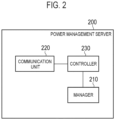
- the power management server 200 includes a manager 210, a communication unit 220, and a controller 230.
- a manager 210 includes a non-volatile memory and/or a storage medium such as an HDD, and manages data on two or more facilities 100 managed by the power management server 200.
- the two or more facilities 100 managed by the power management server 200 may be the facilities 100 having a contract with an entity that manages the power management server 200.
- the data on the facility 100 may be demand power supplied from the power grid to the facility 100.
- the data on the facility 100 may be an amount of power reduced at each facility 100 in response to a demand reduction request (DR; Demand Response) for the entire power grid.
- the data on the facility 100 may be a type of the distributed power supply provided in the facility 100, specifications of the distributed power supply provided in the facility 100, and the like.
- the specifications may be rated power generation (W) of the solar cell apparatus, the maximum output power (W) of the storage battery apparatus, and the maximum output power (W) of the fuel cell apparatus.
- the data on the facility 100 may be the amount of output power instructed to the distributed power supply in the past.
- the data on the facility 100 may be the amount of discharge power instructed to the storage battery apparatus.
- the data on the facility 100 may be the degree of deterioration of the distributed power supply.
- the data on the facility 100 may be SOH (State Of Health) of the storage battery apparatus.
- the manager 210 manages the evaluation value associated with a power source that supplies the power to the power purchasing facility.
- the power source include the solar cell apparatus, the storage battery apparatus, the fuel cell apparatus, the thermal power plant, the nuclear power plant, and the wind power plant.
- the manager 210 may manage an index value used for calculating the evaluation value. Examples of the index value include stability, expected value, CO2 emissions, distributed power supply, operating cost, and damage risk.
- the stability is an index value related to the degree to which supply of power can be stably continued. It is considered that the index value of the stability is relatively low for the storage battery apparatus whose remaining charge may fluctuate, the solar cell apparatus whose power generation amount may fluctuate depending on an amount of solar radiation, and the wind power plant whose power generation amount may fluctuate depending on an air flow rate.
- the expected value is an index value related to the degree to which the supply of power can be expected. It is considered that the index value of the expected value is relatively low for the solar cell apparatus, the storage battery apparatus, and the fuel cell apparatus, which are affected by the power consumption, the remaining charge, the amount of solar radiation, or the like of the facility 100. It is considered that the index value of the expected value is relatively low for the wind power plant whose power generation amount may fluctuate depending on the air flow rate.
- the CO2 emissions are an index value related to the CO2 amount emitted by the power source. Since the fuel cell apparatus and the thermal power plant are considered to have high CO2 emissions, the index value of CO2 emissions is considered to be relatively low.
- the distributed power supply is an index value indicating whether the power source is the distributed power supply. If the power source is the distributed power supply, since local production for local consumption can be expected, the index value of the distributed power supply is considered to be high.
- the operating cost is an index value related to the operating cost of the power source.
- the index value of the operating cost is considered to be high because natural energy is used.
- the damage risk is an index value related to a risk of damage for a disaster. As for the thermal power plant and the nuclear power plant, the index value of the damage risk is considered to be low because the damage for the disaster is large.
- the evaluation value associated with the power source used for selling power is determined based on the stability, the expected value, the CO2 emissions, the operating cost, and the damage risk.
- the evaluation value associated with the power source used for selling power may be determined based on at least one of the stability, the expected value, the CO2 emissions, the operating cost, and the damage risk.
- the communication unit 220 includes a communication module, and communicates with the facility 100 through the network 400. As described above, the communication unit 220 performs communication according to the first protocol. For example, the communication unit 220 transmits a first message to the facility 100 according to the first protocol. The communication unit 220 receives a first message response from the facility 100 according to the first protocol.
- the communication unit 220 communicates with the user terminal 500.
- the communication unit 220 receives a message (a score request) requesting the score of the power source provided in the power selling facility from the user terminal 500.
- the communication unit 220 transmits a message (a score response) including the score of the power source provided in the power selling facility to the user terminal 500. That is, the communication unit 220 constitutes notifies the user terminal 500 of the score.
- the controller 230 includes a memory, a CPU, and the like, and controls each component provided in the power management server 200. For example, the controller 230 transmits a control message to instruct the facility 100 to control the distributed power supply provided in the facility 100. As described above, the control message may be a tidal current control message, a reverse tidal current control message, or a power supply control message.
- the controller 230 extracts a power selling facility other than the power purchasing facility from two or more facilities by an input from the user terminal 500 corresponding to the power purchasing facility (for example, the facility 100P).
- the controller 230 calculates the score indicating a value of purchase and sale of the power based on a communication time in a communication path between the power selling facility and the power purchasing facility.
- the input from the user terminal 500 is the score request described above.
- the score request may include an information element that specifies all or part of the power selling facility that can supply power to the power purchasing facility.
- the information element that specifies a part of the power selling facility may include an information element that indicates a condition that the distance of the power path to the base power supply is equal to or greater than the threshold value.
- Such an information element may include an information element indicating a condition that the facility is connected to the low voltage power line.
- the information element that specifies a part of the power selling facility may include an information element indicating the condition that the facility is connected to the low voltage power line to which the power purchasing facility is connected.
- the information elements that specify a part of the power selling facility may include an information element indicating conditions that the stability is high, the expected value is high, the CO2 emissions are low, the power source is the distributed power supply, the operating cost is low, and the damage risk is low, or the like.
- the communication time in the communication path may be represented by an RTT (Round Trip Time) between the power selling facility and the power purchasing facility.
- RTT und Trip Time
- the RTT between the power selling facility and the power purchasing facility is a total of the RTT between the power selling facility and the power management server 200 and the RTT between the power purchasing facility and the power management server 200.
- the facility 100P is the power purchasing facility
- the facility 100A to the facility 100F and the facility 300A to the facility 300C are candidates for the power selling facility.
- the controller 230 calculates the score indicating the value of purchase and sale of the power by correcting the evaluation value shown in Fig. 3 by the communication time (RTT) in the communication path. Specifically, the controller 230 corrects the evaluation value so that the score is higher as the RTT is smaller.
- RTT communication time
- the controller 230 calculates the score based on the type of the power source.
- the evaluation value shown in Fig. 3 is determined based on at least one of the stability, the expected value, the CO2 emissions, the operating cost, and the damage risk. Therefore, as a result, the controller 230 calculates the score based on at least one of the stability, the expected value, the CO2 emissions, the operating cost, and the damage risk.
- the controller 230 may exclude a facility having a distance of the power path to the base power supply less than the threshold value from the candidates for the power selling facility.
- the controller 230 may exclude the facility 300A to the facility 300C from the candidates for the power selling facility.
- the exclusion may be a process of calculating the score as zero, or a process of not extracting as the power selling facility.
- the controller 230 may exclude a facility that is not connected to the low voltage power line to which the power purchasing facility is connected from the candidates for the power selling facility. That is, in this case, the power selling facility is the facility connected to the low voltage power line to which the power purchasing facility is connected.
- the controller 230 may exclude the facility 100D to the facility 100F from the candidates for the power selling facility.
- the exclusion may be a process of calculating the score as zero, or a process of not extracting as the power selling facility.
- the controller 230 may calculate the score based on the amount of power that can be output from the power source (hereinafter, referred to as an output power capacity).
- the output power capacity may be the amount of power that the distributed power supply can be the reverse power flow.
- the controller 230 calculates the score so that the score is lower as the output power capacity is smaller than a power purchase amount requested by the user of the power purchasing facility.
- the controller 230 may exclude a facility having an output power capacity smaller than the power purchase amount from the candidates for the power selling facility.
- Step S10 the user terminal 500 transmits the message (score request) requesting the score of the power source provided in the power selling facility to the power management server 200.
- the score request may include the information element that specifies all or part of the power selling facility that can supply power to the power purchasing facility.
- Step S20 the power management server 200 extracts the power selling facility other than the power purchasing facility from two or more facilities by the input from the user terminal 500 corresponding to the power purchasing facility.
- Step S30 the power management server 200 calculates the score indicating the value of purchase and sale of the power based on the communication time in the communication path between the power selling facility and the power purchasing facility. For example, the power management server 200 calculates the score shown in Fig. 4 . Since a method of calculating the score is as described above, details thereof will be omitted.
- Step S40 the power management server 200 transmits the message (score response) including the score of the power source provided in the power selling facility to the user terminal 500.
- Step S50 the user terminal 500 transmits a message (power purchase request) including an information element indicating the power selling facility selected by the user to the power management server 200.
- the user terminal 500 may display a list of scores shown in Fig. 4 in order to allow the user to select the power selling facility in response to receiving the score response.
- Step S60 when the matching between the power purchasing facility and the power selling facility is established, the power management server 200 transmits a message (power purchase response) including an information element indicating the establishment of the matching to the user terminal 500.
- the power management server 200 may send the message (power purchase response) including an information element indicating unsuccessful matching to the user terminal 500.
- the description will proceed assuming that the matching has been established.
- Step S70 the power management server 200 transmits a message (an output instruction) instructing the power selling facility to output power to the power selling facility selected by the user.
- Step S80 the power selling facility outputs power to the power grid.
- Fig. 5 for the sake of clarity, a diagram in which the power is supplied from the power selling facility to the power purchasing facility is illustrated, however, this is not intended to supply power directly from the power selling facility to the power purchasing facility by a dedicated power line.
- An operation of outputting power from the power selling facility to the power grid and an operation of supplying power from the power grid to the power purchasing facility may be performed separately, and in the case of purchase and sale of the power in real time, these operations may be performed at substantially the same timing when the matching is established.
- the power management server 200 calculates the score indicating the value of purchase and sale of the power based on the communication time in the communication path between the power selling facility and the power purchasing facility. According to such a configuration, in the case of purchase and sale of the power in real time, the matching between the power purchasing facility and the power selling facility can be appropriately realized.
- the facility 100 constitutes an ad-hoc network including a wireless communication network.
- the ad-hoc network may include a wired communication network instead of the wireless communication network. In such a case, the communication path between the power purchasing facility and the power selling facility does not need to pass through the power management server 200.
- the power management server 200 manages the number of hops between the facilities 100.
- the number of hops is represented by the number of facilities 100 provided in the communication path.
- the number of hops may be notified from the facility 100.
- the power management server 200 corrects the evaluation value shown in Fig. 3 by the communication time (the number of hops) in the communication path, to calculate the score indicating the value of purchase and sale of the power. Specifically, the controller 230 corrects the evaluation value so that the score is higher as the number of hops is smaller. In other words, the power management server 200 may generate the list of scores shown in Fig. 7 instead of the list of scores shown in Fig. 4 .
- the power purchase request includes the information element indicating the power selling facility selected by the user.
- the power purchase request may include an information element indicating the power source selected by the user in addition to the information element indicating the power selling facility selected by the user. That is, when the power selling facility has two or more types of power sources, since the scores of the two or more types of power sources are different, the user may be able to select the power source provided in the power selling facility.
- the user terminal 500 may be considered to be synonymous with the power purchasing facility.
- the user terminal 500 may be a terminal provided in the power purchasing facility.
- the communication time in the communication path may be the communication time in the communication path between the user terminal 500 and the power selling facility.
- the user terminal 500 may be a terminal during staying or due to stay at the power purchasing facility.
- a usage scene include a usage scene in which the user of the user terminal 500 charges an electric vehicle at a friend's house when the power purchasing facility is the friend's house, and a usage scene in which the user of the user terminal 500 charges the smartphone at a restaurant when the power purchasing facility is the restaurant.
- the evaluation value is determined based on at least one of the stability, the expected value, the CO2 emissions, the operating cost, and the damage risk.
- the evaluation value may be set by the user of the power purchasing facility.
- the evaluation value may be determined in advance.
- extraction of the power selling facility and calculation of the score is performed by the power management server 200.
- the embodiment is not limited to this.
- the extraction of the power selling facility and the calculation of the score may be performed by any apparatus as long as it is an apparatus connected to the network 410.
- the extraction of the power selling facility and the calculation of the score may be performed by cooperation of two or more apparatuses.
- the extraction of the power selling facility and the calculation of the score may be performed by the user terminal 500, may be performed by one or more terminals belonging to users of the power selling facilities, and may be performed by a cloud server that can be accessed by two or more user terminals.
Landscapes
- Engineering & Computer Science (AREA)
- Power Engineering (AREA)
- Business, Economics & Management (AREA)
- Health & Medical Sciences (AREA)
- Economics (AREA)
- Physics & Mathematics (AREA)
- General Physics & Mathematics (AREA)
- Public Health (AREA)
- General Business, Economics & Management (AREA)
- Marketing (AREA)
- Primary Health Care (AREA)
- Strategic Management (AREA)
- Tourism & Hospitality (AREA)
- General Health & Medical Sciences (AREA)
- Human Resources & Organizations (AREA)
- Water Supply & Treatment (AREA)
- Theoretical Computer Science (AREA)
- Management, Administration, Business Operations System, And Electronic Commerce (AREA)
- Supply And Distribution Of Alternating Current (AREA)
- Remote Monitoring And Control Of Power-Distribution Networks (AREA)
- Human Computer Interaction (AREA)
- Automation & Control Theory (AREA)
Description
- The present invention relates to a power management system and a power management method.
- Prior art which is related to this field is disclosed in
US 2011/055036 A1 showing methods and systems for managing electricity delivery and commerce,US 2016/313754 A1 showing power control device, power management device and power management system and inUS 2018/167298 A1 showing measurement of application response delay time. - In recent years, a technique using a distributed power supply provided in a facility (for example, VPP (Virtual Power Plant)) in order to maintain a balance between supply and demand of power in a power grid has been known (for example, Patent Literature 1). Furthermore, the power trading market, which realizes purchase and sale of power, is also attracting attention as a method of using the distributed power supply provided in the facility.
- Patent Literature 1:
Japanese application publication No. 2005-182399 - A power management system according to a first feature is for providing a mechanism of power transaction between two or more facilities connected to a power grid. The power management system includes a controller and a communication unit. The controller is configured to extract, from two or more facilities, a first facility to sell power other than a second facility to purchase power by an input from a user terminal corresponding to the second facility which is one of the two or more facilities, and calculate a score indicating an evaluation of the first facility based on a communication time in a communication path between the first facility and the second facility. The communication unit is configured to notify the user terminal of the score.
- A power management method according to a second feature is for providing a mechanism of power transaction between two or more facilities connected to a power grid. The power management method includes the steps of: extracting, from two or more facilities, a first facility to sell power other than a second facility to purchase power by an input from a user terminal corresponding to the second facility which is one of the two or more facilities; calculating a score indicating an evaluation of the first facility based on a communication time in a communication path between the first facility and the second facility; and notifying the user terminal of the score.
-
-
Fig. 1 is a diagram illustrating apower management system 10 according to an embodiment. -
Fig. 2 is a diagram illustrating apower management server 200 according to the embodiment. -
Fig. 3 is a diagram for explaining an evaluation value according to the embodiment. -
Fig. 4 is a diagram for explaining a score according to the embodiment. -
Fig. 5 is a diagram illustrating a power management method according to the embodiment. -
Fig. 6 is a diagram illustrating thepower management system 10 according to a modification. -
Fig. 7 is a diagram for explaining the score according to the modification. - In the power trading market described above, the purchase and sale of power is realized by matching selling bid for power and buying bid for power. In general, since it is possible to cover the power consumption of the facility with a base power supply connected to a high-voltage power grid or the like, the above-mentioned matching is not required to be in real-time, and can be performed virtually.
- However, assuming a case where power is bought and sold in real-time between facilities in which a distance of a power path to the base power supply is equal to or greater than a threshold value (for example, facilities connected to a low-voltage power grid), there is a possibility that the power consumption of the facility cannot be quickly covered by the base power supply. Therefore, if the timing of reverse power flow from the facility to the power grid (selling bid for power) and the timing of power flow from the power grid to the facility (buying bid for power) are not met, the balance between supply and demand of power of the power grid in an area where the facility is provided may be lost.
- Therefore, the present disclosure has been made in order to solve the above-mentioned problems, and provides a power management system and a power management method that can appropriately realize matching between a power purchasing facility and a power selling facility.
- Hereinafter, embodiments will be described with reference to the drawings. In the following description of the drawings, the same or similar parts are denoted by the same or similar reference numerals.
- However, it should be noted that the drawings are schematic and ratios of each dimension may be different from actual dimensions. Therefore, specific dimensions should be determined in consideration of the following description. In addition, it is needless to say that the drawings may include portions having different dimensional relationships or ratios.
- The power management system according to an embodiment will be described below. A
power management system 10 includes afacility 100, apower management server 200, afacility 300, anetwork 410, asubstation equipment 420, and auser terminal 500. - The
facility 100 is connected to a low voltage power line. The low voltage power line is an example of the power grid, and is a power line corresponding to a voltage lower than that of a high voltage power line. Although not particularly limited, thefacility 100 is a relatively small facility. For example, thefacility 100 has load equipment such as air conditioning equipment, lighting equipment, and AV (Audio Visual) equipment.Facility 100 may have a distributed power supply such as a solar cell apparatus, a storage battery apparatus, and a fuel cell apparatus. - For example, a
facility 100P does not have the distributed power supply. Afacility 100A has the solar cell apparatus. Afacility 100B has the solar cell apparatus and the storage battery apparatus. Afacility 100C has the solar cell apparatus. Afacility 100D has the solar cell apparatus, the storage battery apparatus and the fuel cell apparatus. Afacility 100E has the solar cell apparatus and the storage battery apparatus. Afacility 100F does not have the distributed power supply. - Here, the
facility 100P, thefacility 100A, thefacility 100B and thefacility 100C are connected to the same lowvoltage power line 421. Thefacility 100D, thefacility 100E and thefacility 100F are connected to the same lowvoltage power line 422. The lowvoltage power line 421 and the lowvoltage power line 422 are branched at thesubstation equipment 420, and may be considered as different low voltage power lines. - In the following, a flow of power from the low voltage power line to the
facility 100 may be referred to as a power flow. The flow of power from thefacility 100 to the low voltage power line may be referred to as a reverse power flow. - The
power management server 200 is a server that provides a mechanism for purchase and sale of the power between two or more facilities. Specifically, thepower management server 200 matches the power purchasing facility that intends to purchase power with the power selling facility that intends to sell power. In the embodiment, thefacility 100P is an example of the power purchasing facility. Thefacilities 100A to 100F are candidates for the power selling facility.Facilities 300A to 300C, which will be described below, may also be candidates for the power selling facility. - The
power management server 200 may be a server managed by a power operator such as a power generation operator, a power distribution operator, a retailer, or a resource aggregator. The resource aggregator is a power operator that provides the reverse tidal current power to the power generation operator, the power distribution operator, the retailer, and the like in a virtual power plant (VPP). The resource aggregator may be a power operator that produces surplus power (negawatt power) by reducing the consumed power of the facility managed by the resource aggregator. Such surplus power may be regarded as generated power. The resource aggregator may be a power operator that absorbs excessive power by increasing the consumed power of the facility managed by the resource aggregator (for example, increasing the charge amount of the storage battery apparatus). - The
power management server 200 transmits, to thefacility 100, a control message instructing control of a distributed power supply provided in thefacility 100. For example, thepower management server 200 may transmit a tidal current control message (for example, demand response (DR)) requesting the control of the tidal current. Thepower management server 200 may transmit the reverse tidal current control message requesting the control of the reverse tidal current. Further, thepower management server 200 may transmit a power supply control message that controls an operating state of the distributed power supply. A degree of control of the tidal current or the reverse tidal current may be represented by an absolute value (for example, oo kW) or a relative value (for example, oo%). Alternatively, the degree of control of the tidal current or the reverse tidal current may be represented by two or more levels. The degree of control of the tidal current or the reverse tidal current may be represented by a power rate (real time pricing (RTP)) defined by the current power demand and supply balance. The degree of control of the tidal current or the reverse tidal current may be represented by a power rate (time of use (TOU)) defined by the past power demand and supply balance. - The
facility 300 is connected to the high voltage power line. The high voltage power line is an example of the power grid, and is a power line corresponding to a voltage higher than that of the low voltage power line. Although not particularly limited, thefacility 300 is a relatively large-scale facility. - For example, the
facility 300A is a thermal power plant. Thefacility 300B is a nuclear power plant. Thefacility 300C is a wind power plant. However, thefacility 300 may be a facility having a large number of solar cell apparatuses. Thefacility 300 may be a facility having a large number of storage battery apparatuses. Thefacility 300A to thefacility 300A to thefacility 300C is an example of the base power supply. - The
network 410 is a network that connects thefacility 100, thepower management server 200, and thefacility 300. Although not particularly limited, thenetwork 410 may be a dedicated line such as a VPN (Virtual Private Network). - The
substation equipment 420 is equipment that converts the voltage of the high voltage power line into the voltage of the low voltage power line. A plurality of low voltage power lines may be connected to thesubstation equipment 420. A plurality of high voltage power lines may be connected to thesubstation equipment 420. - The
user terminal 500 is a terminal belonging to a user of thefacility 100P. Theuser terminal 500 may be a terminal such as a personal computer, a smartphone, or a tablet PC. - In the embodiment, communication between the
power management server 200 and thefacility 100 may be performed according to a first protocol. On the other hand, communication between thefacility 100 and the distributed power supply may be performed according to a second protocol different from the first protocol. Further, communication between thepower management server 200 and the distributed power supply may be performed according to the first protocol. For example, as the first protocol, a protocol conforming to open automated demand response (Open ADR) or an original dedicated protocol can be used. For example, as the second protocol, a protocol conforming to ECHONET Lite, smart energy profile (SEP) 2.0, KNX, or the original dedicated protocol can be used. - The power management server according to the embodiment will be described below. As illustrated in
Fig. 2 , thepower management server 200 includes amanager 210, acommunication unit 220, and acontroller 230. - A
manager 210 includes a non-volatile memory and/or a storage medium such as an HDD, and manages data on two ormore facilities 100 managed by thepower management server 200. The two ormore facilities 100 managed by thepower management server 200 may be thefacilities 100 having a contract with an entity that manages thepower management server 200. For example, the data on thefacility 100 may be demand power supplied from the power grid to thefacility 100. The data on thefacility 100 may be an amount of power reduced at eachfacility 100 in response to a demand reduction request (DR; Demand Response) for the entire power grid. The data on thefacility 100 may be a type of the distributed power supply provided in thefacility 100, specifications of the distributed power supply provided in thefacility 100, and the like. The specifications may be rated power generation (W) of the solar cell apparatus, the maximum output power (W) of the storage battery apparatus, and the maximum output power (W) of the fuel cell apparatus. Further, the data on thefacility 100 may be the amount of output power instructed to the distributed power supply in the past. For example, when the distributed power supply is the storage battery apparatus, the data on thefacility 100 may be the amount of discharge power instructed to the storage battery apparatus. The data on thefacility 100 may be the degree of deterioration of the distributed power supply. For example, when the distributed power supply is the storage battery apparatus, the data on thefacility 100 may be SOH (State Of Health) of the storage battery apparatus. - In the embodiment, as illustrated in
Fig. 3 , themanager 210 manages the evaluation value associated with a power source that supplies the power to the power purchasing facility. Examples of the power source include the solar cell apparatus, the storage battery apparatus, the fuel cell apparatus, the thermal power plant, the nuclear power plant, and the wind power plant. Themanager 210 may manage an index value used for calculating the evaluation value. Examples of the index value include stability, expected value, CO2 emissions, distributed power supply, operating cost, and damage risk. - The stability is an index value related to the degree to which supply of power can be stably continued. It is considered that the index value of the stability is relatively low for the storage battery apparatus whose remaining charge may fluctuate, the solar cell apparatus whose power generation amount may fluctuate depending on an amount of solar radiation, and the wind power plant whose power generation amount may fluctuate depending on an air flow rate.
- The expected value is an index value related to the degree to which the supply of power can be expected. It is considered that the index value of the expected value is relatively low for the solar cell apparatus, the storage battery apparatus, and the fuel cell apparatus, which are affected by the power consumption, the remaining charge, the amount of solar radiation, or the like of the
facility 100. It is considered that the index value of the expected value is relatively low for the wind power plant whose power generation amount may fluctuate depending on the air flow rate. - The CO2 emissions are an index value related to the CO2 amount emitted by the power source. Since the fuel cell apparatus and the thermal power plant are considered to have high CO2 emissions, the index value of CO2 emissions is considered to be relatively low.
- The distributed power supply is an index value indicating whether the power source is the distributed power supply. If the power source is the distributed power supply, since local production for local consumption can be expected, the index value of the distributed power supply is considered to be high.
- The operating cost is an index value related to the operating cost of the power source. As for the solar cell apparatus and the wind power plant, the index value of the operating cost is considered to be high because natural energy is used.
- The damage risk is an index value related to a risk of damage for a disaster. As for the thermal power plant and the nuclear power plant, the index value of the damage risk is considered to be low because the damage for the disaster is large.
- In
Fig. 3 , the evaluation value associated with the power source used for selling power is determined based on the stability, the expected value, the CO2 emissions, the operating cost, and the damage risk. However, the embodiment is not limited to this. The evaluation value associated with the power source used for selling power may be determined based on at least one of the stability, the expected value, the CO2 emissions, the operating cost, and the damage risk. - The
communication unit 220 includes a communication module, and communicates with thefacility 100 through the network 400. As described above, thecommunication unit 220 performs communication according to the first protocol. For example, thecommunication unit 220 transmits a first message to thefacility 100 according to the first protocol. Thecommunication unit 220 receives a first message response from thefacility 100 according to the first protocol. - In the embodiment, the
communication unit 220 communicates with theuser terminal 500. Thecommunication unit 220 receives a message (a score request) requesting the score of the power source provided in the power selling facility from theuser terminal 500. Thecommunication unit 220 transmits a message (a score response) including the score of the power source provided in the power selling facility to theuser terminal 500. That is, thecommunication unit 220 constitutes notifies theuser terminal 500 of the score. - The
controller 230 includes a memory, a CPU, and the like, and controls each component provided in thepower management server 200. For example, thecontroller 230 transmits a control message to instruct thefacility 100 to control the distributed power supply provided in thefacility 100. As described above, the control message may be a tidal current control message, a reverse tidal current control message, or a power supply control message. - In the embodiment, the
controller 230 extracts a power selling facility other than the power purchasing facility from two or more facilities by an input from theuser terminal 500 corresponding to the power purchasing facility (for example, thefacility 100P). Thecontroller 230 calculates the score indicating a value of purchase and sale of the power based on a communication time in a communication path between the power selling facility and the power purchasing facility. - For example, the input from the
user terminal 500 is the score request described above. The score request may include an information element that specifies all or part of the power selling facility that can supply power to the power purchasing facility. The information element that specifies a part of the power selling facility may include an information element that indicates a condition that the distance of the power path to the base power supply is equal to or greater than the threshold value. Such an information element may include an information element indicating a condition that the facility is connected to the low voltage power line. The information element that specifies a part of the power selling facility may include an information element indicating the condition that the facility is connected to the low voltage power line to which the power purchasing facility is connected. The information elements that specify a part of the power selling facility may include an information element indicating conditions that the stability is high, the expected value is high, the CO2 emissions are low, the power source is the distributed power supply, the operating cost is low, and the damage risk is low, or the like. - For example, the communication time in the communication path may be represented by an RTT (Round Trip Time) between the power selling facility and the power purchasing facility. In the embodiment, since the communication path between the power selling facility and the power purchasing facility passes through the
power management server 200, the RTT between the power selling facility and the power purchasing facility is a total of the RTT between the power selling facility and thepower management server 200 and the RTT between the power purchasing facility and thepower management server 200. - For example, consider a case where the
facility 100P is the power purchasing facility, and thefacility 100A to thefacility 100F and thefacility 300A to thefacility 300C are candidates for the power selling facility. - As illustrated in
Fig. 4 , thecontroller 230 calculates the score indicating the value of purchase and sale of the power by correcting the evaluation value shown inFig. 3 by the communication time (RTT) in the communication path. Specifically, thecontroller 230 corrects the evaluation value so that the score is higher as the RTT is smaller. - In the embodiment, the evaluation value shown in
Fig. 3 varies depending on the type of the power source. Therefore, as a result, thecontroller 230 calculates the score based on the type of the power source. - In the embodiment, the evaluation value shown in
Fig. 3 is determined based on at least one of the stability, the expected value, the CO2 emissions, the operating cost, and the damage risk. Therefore, as a result, thecontroller 230 calculates the score based on at least one of the stability, the expected value, the CO2 emissions, the operating cost, and the damage risk. - The
controller 230 may exclude a facility having a distance of the power path to the base power supply less than the threshold value from the candidates for the power selling facility. For example, thecontroller 230 may exclude thefacility 300A to thefacility 300C from the candidates for the power selling facility. The exclusion may be a process of calculating the score as zero, or a process of not extracting as the power selling facility. - The
controller 230 may exclude a facility that is not connected to the low voltage power line to which the power purchasing facility is connected from the candidates for the power selling facility. That is, in this case, the power selling facility is the facility connected to the low voltage power line to which the power purchasing facility is connected. For example, thecontroller 230 may exclude thefacility 100D to thefacility 100F from the candidates for the power selling facility. The exclusion may be a process of calculating the score as zero, or a process of not extracting as the power selling facility. - The
controller 230 may calculate the score based on the amount of power that can be output from the power source (hereinafter, referred to as an output power capacity). When the power source is the distributed power supply, the output power capacity may be the amount of power that the distributed power supply can be the reverse power flow. For example, thecontroller 230 calculates the score so that the score is lower as the output power capacity is smaller than a power purchase amount requested by the user of the power purchasing facility. Thecontroller 230 may exclude a facility having an output power capacity smaller than the power purchase amount from the candidates for the power selling facility. - The power management method according to the embodiment will be described below.
- As illustrated in
Fig. 5 , in Step S10, theuser terminal 500 transmits the message (score request) requesting the score of the power source provided in the power selling facility to thepower management server 200. As described above, the score request may include the information element that specifies all or part of the power selling facility that can supply power to the power purchasing facility. - In Step S20, the
power management server 200 extracts the power selling facility other than the power purchasing facility from two or more facilities by the input from theuser terminal 500 corresponding to the power purchasing facility. - In Step S30, the
power management server 200 calculates the score indicating the value of purchase and sale of the power based on the communication time in the communication path between the power selling facility and the power purchasing facility. For example, thepower management server 200 calculates the score shown inFig. 4 . Since a method of calculating the score is as described above, details thereof will be omitted. - In Step S40, the
power management server 200 transmits the message (score response) including the score of the power source provided in the power selling facility to theuser terminal 500. - In Step S50, the
user terminal 500 transmits a message (power purchase request) including an information element indicating the power selling facility selected by the user to thepower management server 200. Here, theuser terminal 500 may display a list of scores shown inFig. 4 in order to allow the user to select the power selling facility in response to receiving the score response. - In Step S60, when the matching between the power purchasing facility and the power selling facility is established, the
power management server 200 transmits a message (power purchase response) including an information element indicating the establishment of the matching to theuser terminal 500. When the matching between the power purchasing facility and the power selling facility is not established, thepower management server 200 may send the message (power purchase response) including an information element indicating unsuccessful matching to theuser terminal 500. In the following, the description will proceed assuming that the matching has been established. - In Step S70, the
power management server 200 transmits a message (an output instruction) instructing the power selling facility to output power to the power selling facility selected by the user. - In Step S80, the power selling facility outputs power to the power grid. In
Fig. 5 , for the sake of clarity, a diagram in which the power is supplied from the power selling facility to the power purchasing facility is illustrated, however, this is not intended to supply power directly from the power selling facility to the power purchasing facility by a dedicated power line. An operation of outputting power from the power selling facility to the power grid and an operation of supplying power from the power grid to the power purchasing facility may be performed separately, and in the case of purchase and sale of the power in real time, these operations may be performed at substantially the same timing when the matching is established. - In the embodiment, the
power management server 200 calculates the score indicating the value of purchase and sale of the power based on the communication time in the communication path between the power selling facility and the power purchasing facility. According to such a configuration, in the case of purchase and sale of the power in real time, the matching between the power purchasing facility and the power selling facility can be appropriately realized. - For example, in the case of providing the mechanism for purchase and sale of the power between two or more facilities in which the distance of the power path to the base power supply is equal to or greater than the threshold value, it is possible to suppress imbalance between supply and demand of power caused by a difference between the timing of the reverse power flow and the timing of the power flow.
- A modification of the embodiment will be described below. In the following, differences from the embodiments will be mainly described.
- In the embodiment, a case where the RTT is used as the communication time in the communication path has been described. In contrast, in the modification, a case where the number of hops is used as the communication time in the communication path will be described.
- As illustrated in
Fig. 6 , in thepower management system 10, thefacility 100 constitutes an ad-hoc network including a wireless communication network. The ad-hoc network may include a wired communication network instead of the wireless communication network. In such a case, the communication path between the power purchasing facility and the power selling facility does not need to pass through thepower management server 200. - In such a case, the
power management server 200 manages the number of hops between thefacilities 100. The number of hops is represented by the number offacilities 100 provided in the communication path. The number of hops may be notified from thefacility 100. - Specifically, as illustrated in
Fig. 7 , thepower management server 200 corrects the evaluation value shown inFig. 3 by the communication time (the number of hops) in the communication path, to calculate the score indicating the value of purchase and sale of the power. Specifically, thecontroller 230 corrects the evaluation value so that the score is higher as the number of hops is smaller. In other words, thepower management server 200 may generate the list of scores shown inFig. 7 instead of the list of scores shown inFig. 4 . - Although the present disclosure has been described by the embodiments described above, the statements and drawings that form a part of this disclosure should not be understood to limit this invention. Various alternative embodiments, examples and operational techniques will be apparent to those skilled in the art from this disclosure.
- In the embodiment, the power purchase request includes the information element indicating the power selling facility selected by the user. However, the embodiment is not limited to this. The power purchase request may include an information element indicating the power source selected by the user in addition to the information element indicating the power selling facility selected by the user. That is, when the power selling facility has two or more types of power sources, since the scores of the two or more types of power sources are different, the user may be able to select the power source provided in the power selling facility.
- Although not particularly mentioned in the embodiment, the
user terminal 500 may be considered to be synonymous with the power purchasing facility. In such a case, theuser terminal 500 may be a terminal provided in the power purchasing facility. The communication time in the communication path may be the communication time in the communication path between theuser terminal 500 and the power selling facility. - Although not particularly mentioned in the embodiment, the
user terminal 500 may be a terminal during staying or due to stay at the power purchasing facility. Examples of such a usage scene include a usage scene in which the user of theuser terminal 500 charges an electric vehicle at a friend's house when the power purchasing facility is the friend's house, and a usage scene in which the user of theuser terminal 500 charges the smartphone at a restaurant when the power purchasing facility is the restaurant. - In the embodiment, the evaluation value is determined based on at least one of the stability, the expected value, the CO2 emissions, the operating cost, and the damage risk. However, the embodiment is not limited to this. The evaluation value may be set by the user of the power purchasing facility. The evaluation value may be determined in advance.
- In the embodiment, extraction of the power selling facility and calculation of the score is performed by the
power management server 200. However, the embodiment is not limited to this. The extraction of the power selling facility and the calculation of the score may be performed by any apparatus as long as it is an apparatus connected to thenetwork 410. The extraction of the power selling facility and the calculation of the score may be performed by cooperation of two or more apparatuses. The extraction of the power selling facility and the calculation of the score may be performed by theuser terminal 500, may be performed by one or more terminals belonging to users of the power selling facilities, and may be performed by a cloud server that can be accessed by two or more user terminals.
Claims (20)
- A power management system (10) for providing a mechanism of power transaction between two or more facilities (100) connected to a power grid, the system (10) comprising:a controller (230) configured toextract, from two or more facilities (100), a first facility to sell power other than a second facility to purchase power by an input from a user terminal (500) corresponding to the second facility which is one of the two or more facilities (100), andcalculate a score indicating an evaluation of the first facility based on a communication time in a communication path between the first facility and the second facility; anda communication unit (220) configured to notify the user terminal (500) of the score.
- The power management system (10) according to claim 1, wherein in the two or more facilities (100), a distance of a power path to a base power supply is equal to or greater than a threshold value.
- The power management system (10) according to claim 1 or 2, wherein the communication path passes through a power management server (200) including the controller (230) and the communication unit (220).
- The power management system (10) according to any one of claims 1 to 3, wherein the controller (230) is configured to calculate the score based on a type of a power source of the first facility.
- The power management system (10) according to any one of claims 1 to 4, wherein the controller (230) is configured to calculate the score based on power which can be output from a power source of the first facility.
- The power management system (10) according to any one of claims 1 to 5, wherein the controller (230) is configured to calculate the score based on at least one of stability, expected value, CO2 emissions, operating cost, and damage risk when power is output from a power source of the first facility.
- The power management system (10) according to any one of claims 1 to 6, wherein the communication time includes a Round Trip Time (RTT) between the first facility and the second facility.
- The power management system (10) according to claim 7, wherein the communication path passes through a power management server (200) including the controller (230) and the communication unit (220), and
the RTT is a total of an RTT between the first facility and the power management server (200) and an RTT between the second facility and the power management server (200). - The power management system (10) according to any one of claims 1 to 8, wherein the communication time includes a number of hops in the communication path.
- The power management system (10) according to any one of claims 1 to 9, wherein the first facility is a facility connected to a low voltage power line to which the second facility is connected.
- A power management method for providing a mechanism of power transaction between two or more facilities (100) connected to a power grid, the method comprising the steps of:extracting, from two or more facilities (100), a first facility to sell power other than a second facility to purchase power by an input from a user terminal (500) corresponding to the second facility which is one of the two or more facilities (100);calculating a score indicating an evaluation of the first facility based on a communication time in a communication path between the first facility and the second facility; andnotifying the user terminal (500) of the score.
- The power management method according to claim 11, wherein in the two or more facilities (100), a distance of a power path to a base power supply is equal to or greater than a threshold value.
- The power management method according to claim 11 or 12, wherein the communication path passes through a power management server (200) configured to perform the step of extracting and the step of calculating.
- The power management method according to any one of claims 11 to 13, wherein the step of calculating includes a step of calculating the score based on a type of a power source of the first facility.
- The power management method according to any one of claims 11 to 14, wherein the step of calculating includes a step of calculating the score based on power which can be output from a power source of the first facility.
- The power management method according to any one of claims 11 to 15, wherein the step of calculating includes a step of calculating the score based on at least one of stability, expected value, CO2 emissions, operating cost, and damage risk when power is output from a power source of the first facility.
- The power management method according to any one of claims 11 to 16, wherein the communication time includes a Round Trip Time (RTT) between the first facility and the second facility.
- The power management method according to claim 17, wherein the communication path passes through a power management server (200) configured to perform the step of extracting and the step of calculating, and
the RTT is a total of an RTT between the first facility and the power management server (200) and an RTT between the second facility and the power management server (200). - The power management method according to any one of claims 11 to 18, wherein the communication time includes a number of hops in the communication path.
- The power management method according to any one of claims 11 to 19, wherein the first facility is a facility connected to a low voltage power line to which the second facility is connected.
Applications Claiming Priority (2)
| Application Number | Priority Date | Filing Date | Title |
|---|---|---|---|
| JP2018156876 | 2018-08-24 | ||
| PCT/JP2019/032879 WO2020040261A1 (en) | 2018-08-24 | 2019-08-22 | Electric power management system and electric power management method |
Publications (3)
| Publication Number | Publication Date |
|---|---|
| EP3843228A1 EP3843228A1 (en) | 2021-06-30 |
| EP3843228A4 EP3843228A4 (en) | 2022-05-11 |
| EP3843228B1 true EP3843228B1 (en) | 2024-07-24 |
Family
ID=69592042
Family Applications (1)
| Application Number | Title | Priority Date | Filing Date |
|---|---|---|---|
| EP19851687.4A Active EP3843228B1 (en) | 2018-08-24 | 2019-08-22 | Electric power management system and electric power management method |
Country Status (5)
| Country | Link |
|---|---|
| US (1) | US12057698B2 (en) |
| EP (1) | EP3843228B1 (en) |
| JP (4) | JP7116177B2 (en) |
| CN (1) | CN112585833A (en) |
| WO (1) | WO2020040261A1 (en) |
Families Citing this family (4)
| Publication number | Priority date | Publication date | Assignee | Title |
|---|---|---|---|---|
| JP2021157450A (en) * | 2020-03-26 | 2021-10-07 | 本田技研工業株式会社 | Electricity Trading Systems, Electricity Trading Methods and Programs |
| JP7672044B2 (en) * | 2021-03-01 | 2025-05-07 | パナソニックIpマネジメント株式会社 | Power management system, integrated management system |
| JP7728731B2 (en) * | 2022-05-27 | 2025-08-25 | トヨタホーム株式会社 | Power Transmission System |
| JP7749518B2 (en) * | 2022-06-15 | 2025-10-06 | トヨタホーム株式会社 | Power Transmission System |
Family Cites Families (54)
| Publication number | Priority date | Publication date | Assignee | Title |
|---|---|---|---|---|
| FI107183B (en) * | 1999-02-24 | 2001-06-15 | Goeran Vilhelm Vikstroem | Optimized regional thermal power generation method for combined heat and power and optimized regional thermal power plant |
| JP2001243358A (en) * | 2000-02-25 | 2001-09-07 | Itochu Corp | Method for mediating power selling and buying |
| US20020084655A1 (en) * | 2000-12-29 | 2002-07-04 | Abb Research Ltd. | System, method and computer program product for enhancing commercial value of electrical power produced from a renewable energy power production facility |
| JP2003178117A (en) * | 2001-12-10 | 2003-06-27 | Hitachi Ltd | Procurement and redemption of power generation facility construction and operation funds |
| US20030225661A1 (en) * | 2002-03-11 | 2003-12-04 | Siemens Power Transmission & Distribution L.L.C. | Security constrained optimal dispatch for pricing optimization for electricity markets |
| JP3823867B2 (en) * | 2002-04-11 | 2006-09-20 | 日本電気株式会社 | Communication network control system, control method, node and program |
| RU2331924C2 (en) * | 2002-07-20 | 2008-08-20 | Чикаго Клаймат Иксчендж, Инк. | Trading system amd methods for managing many plants which produce gas emissions and lead to greenhouse effect |
| DE10334397A1 (en) * | 2003-07-28 | 2005-03-10 | Siemens Ag | Reducing energy costs in an industrially operated facility e.g. paper and pulp production involves providing for energy flows of the facility, from its purchase, its conversion in secondary process and its consumption in core process |
| JP2005182399A (en) | 2003-12-18 | 2005-07-07 | Silis:Kk | Store chart management system |
| JP2005284420A (en) * | 2004-03-26 | 2005-10-13 | Tokyo Electric Power Co Inc:The | Power resource transaction system and power resource transaction management server |
| JP2010178504A (en) * | 2009-01-29 | 2010-08-12 | Tokyo Gas Co Ltd | Method of supplying electric power using distributed power supplies and power supply program |
| US9134353B2 (en) * | 2009-02-26 | 2015-09-15 | Distributed Energy Management Inc. | Comfort-driven optimization of electric grid utilization |
| US20100217550A1 (en) * | 2009-02-26 | 2010-08-26 | Jason Crabtree | System and method for electric grid utilization and optimization |
| US20110055036A1 (en) * | 2009-09-03 | 2011-03-03 | Meishar Immediate Community | Methods and systems for managing electricity delivery and commerce |
| US8239280B1 (en) * | 2009-09-21 | 2012-08-07 | Igor Feinberg | Method, medium, and system for adjusting purchasing power values |
| JP5577717B2 (en) * | 2010-01-25 | 2014-08-27 | ソニー株式会社 | How to manage power efficiently |
| JP5707050B2 (en) | 2010-04-09 | 2015-04-22 | 学校法人慶應義塾 | Virtual energy trading system |
| JP5576218B2 (en) * | 2010-09-08 | 2014-08-20 | 積水化学工業株式会社 | Regional power interchange system |
| JP5696877B2 (en) * | 2010-10-01 | 2015-04-08 | 清水建設株式会社 | Operation management device, operation management method, and operation management program |
| JP5790081B2 (en) * | 2011-03-30 | 2015-10-07 | 富士通株式会社 | Power control apparatus, power control program, and power control method |
| JP2012252580A (en) * | 2011-06-03 | 2012-12-20 | Sony Corp | Power control device, power management device and power management system |
| WO2013019990A1 (en) * | 2011-08-02 | 2013-02-07 | Power Assure, Inc. | System and method for using data centers as virtual power plants |
| KR20130076743A (en) * | 2011-12-28 | 2013-07-08 | 엘에스산전 주식회사 | Method for providing service of electric power control plan for electric power control target device, and operating method of charging station managing server |
| US9200621B2 (en) * | 2012-02-16 | 2015-12-01 | Spyros James Lazaris | Transmission system for delivery of dynamic demand response in a renewable energy-based electricity grid infrastructure |
| JP5503677B2 (en) | 2012-03-06 | 2014-05-28 | ヤフー株式会社 | System, information processing method, and computer program |
| US9509176B2 (en) * | 2012-04-04 | 2016-11-29 | Ihi Inc. | Energy storage modeling and control |
| JP6087682B2 (en) * | 2013-03-22 | 2017-03-01 | 大阪瓦斯株式会社 | Electricity supply and demand mediation device |
| BR112015025292A2 (en) * | 2013-04-09 | 2017-07-18 | Siemens Ag | method for operating an entire power supply network, where power generation is decentralized |
| US9215164B2 (en) * | 2013-11-08 | 2015-12-15 | Alcatel Lucent | Multi-source correlation of network topology metrics |
| EP3071977A4 (en) * | 2013-11-22 | 2017-06-14 | Mansfield, Stephen Kenneth | Methods and systems for energy arbitrage |
| CN104036434A (en) * | 2014-06-24 | 2014-09-10 | 国家电网公司 | Evaluation method for load supply capacity of power distribution network |
| EP3190683A4 (en) * | 2014-07-31 | 2017-12-20 | Nec Corporation | Control device, apparatus control device, reporting method, and recording medium |
| EP3197011A4 (en) * | 2014-07-31 | 2017-12-13 | Nec Corporation | Control device, apparatus control device, control method, report reception method, reporting method, and recording medium |
| JP2016063595A (en) * | 2014-09-17 | 2016-04-25 | 株式会社デンソー | Power converter |
| EP3235294B1 (en) * | 2014-12-19 | 2019-12-11 | Orange | Power optimization in heterogenous networks |
| US10261851B2 (en) * | 2015-01-23 | 2019-04-16 | Lightbend, Inc. | Anomaly detection using circumstance-specific detectors |
| JP6626359B2 (en) * | 2015-02-19 | 2019-12-25 | 積水化学工業株式会社 | Power related information presenting apparatus, electric related information presenting method and program |
| US9926852B2 (en) * | 2015-03-03 | 2018-03-27 | General Electric Company | Methods and systems for enhancing control of power plant generating units |
| JP6750609B2 (en) * | 2015-03-23 | 2020-09-02 | 日本電気株式会社 | Power matching device and power matching program |
| US10287988B2 (en) * | 2015-03-27 | 2019-05-14 | General Electric Company | Methods and systems for enhancing operation of power plant generating units and systems |
| EP3308226A4 (en) * | 2015-04-27 | 2019-01-23 | Scuderi Group, Inc. | Method of providing electric power to a host |
| US20180241214A1 (en) * | 2015-08-28 | 2018-08-23 | Kyocera Corporation | Management server, management method, and management system |
| US9992091B2 (en) * | 2015-11-30 | 2018-06-05 | Cisco Technology, Inc. | Performing network topology traces with minimal data collection |
| JP6758881B2 (en) * | 2016-03-31 | 2020-09-23 | 株式会社東芝 | Power supply and demand management support system, power supply and demand management support method and power supply and demand management support program |
| JP6045769B1 (en) * | 2016-05-24 | 2016-12-14 | 三菱電機株式会社 | Power generation amount estimation device, distribution system, and power generation amount estimation method |
| US10530184B2 (en) * | 2016-06-23 | 2020-01-07 | Landis+Gyr Innovations, Inc. | Validating power network models for monitoring and correcting operation of electric power networks |
| US10477449B2 (en) * | 2016-08-26 | 2019-11-12 | Veniam, Inc. | Systems and methods for route selection in a network of moving things, for example including autonomous vehicles |
| CN106529758B (en) * | 2016-09-13 | 2022-09-20 | 国网山东省电力公司青岛供电公司 | Method and device for judging rationality of power supply area of distribution transformer |
| US10599107B2 (en) * | 2016-09-29 | 2020-03-24 | Siemens Aktiengesellschaft | System and method for smart grid dynamic regulation pools |
| US10250475B2 (en) * | 2016-12-08 | 2019-04-02 | A10 Networks, Inc. | Measurement of application response delay time |
| JP2020510945A (en) * | 2017-02-13 | 2020-04-09 | グリディ ホールディングス エルエルシーGriddy Holdings Llc | Method and system for automation of a platform for a utility-related market |
| JP2018156876A (en) | 2017-03-21 | 2018-10-04 | 三井化学株式会社 | Positive electrode for lithium ion secondary battery |
| US10691085B2 (en) * | 2017-06-14 | 2020-06-23 | Inventus Holdings, Llc | Defect detection in power distribution system |
| CN108400590A (en) * | 2018-03-07 | 2018-08-14 | 四川省华森新科信息有限公司 | A kind of micro- energy net ecosystem based on block chain and cloud power supply |
-
2019
- 2019-08-22 EP EP19851687.4A patent/EP3843228B1/en active Active
- 2019-08-22 US US17/270,845 patent/US12057698B2/en active Active
- 2019-08-22 JP JP2020538469A patent/JP7116177B2/en active Active
- 2019-08-22 CN CN201980055040.7A patent/CN112585833A/en active Pending
- 2019-08-22 WO PCT/JP2019/032879 patent/WO2020040261A1/en not_active Ceased
-
2022
- 2022-07-28 JP JP2022120999A patent/JP7439185B2/en active Active
- 2022-07-28 JP JP2022121002A patent/JP7376649B2/en active Active
-
2023
- 2023-09-11 JP JP2023147179A patent/JP7618753B2/en active Active
Also Published As
| Publication number | Publication date |
|---|---|
| US20210344221A1 (en) | 2021-11-04 |
| JP2022160536A (en) | 2022-10-19 |
| EP3843228A4 (en) | 2022-05-11 |
| JP2022160537A (en) | 2022-10-19 |
| EP3843228A1 (en) | 2021-06-30 |
| JP7116177B2 (en) | 2022-08-09 |
| JP2023169250A (en) | 2023-11-29 |
| JP7439185B2 (en) | 2024-02-27 |
| US12057698B2 (en) | 2024-08-06 |
| JPWO2020040261A1 (en) | 2021-09-30 |
| WO2020040261A1 (en) | 2020-02-27 |
| JP7376649B2 (en) | 2023-11-08 |
| CN112585833A (en) | 2021-03-30 |
| JP7618753B2 (en) | 2025-01-21 |
Similar Documents
| Publication | Publication Date | Title |
|---|---|---|
| US20240308383A1 (en) | Method and apparatus for charging a battery using local power grid topology information | |
| JP7618753B2 (en) | Power management system, power management method and program | |
| US10461535B2 (en) | Power management system, power management method, and computer program | |
| US11362516B2 (en) | Power management server and power management method | |
| JP2021158839A (en) | Power trading system and management equipment | |
| JP7354394B2 (en) | Power management device and power management method | |
| US11621563B2 (en) | System for dynamic demand balancing in energy networks | |
| US20240380214A1 (en) | Power management apparatus and power management method | |
| JP2020089147A (en) | Power management server and power management method | |
| JP7592021B2 (en) | Bidding support system and bidding support method | |
| US20180083481A1 (en) | Information processing apparatus and method, and computer program product | |
| JP7037583B2 (en) | Power management system, power management server and power management method | |
| JP7486653B1 (en) | Apparatus, method and program | |
| US20220405833A1 (en) | Transaction assistance system and transaction assistance method | |
| Khojasteh et al. | Optimal Strategy of Energy Storage Aggregators in Ancillary Service Markets: Stochastic Programming Approach | |
| WO2018181732A1 (en) | Power supply control method, second provider server, and control device | |
| WO2021060142A1 (en) | Electrical power management system and electrical power management method | |
| Jahromi et al. | Bayesian game model to analyze electric vehicles and smart grid interaction | |
| JP2023005124A (en) | Power management device, power management system, and power management method | |
| Hoog et al. | The role of electric vehicles in demand response: implementation, network impacts and market requirements |
Legal Events
| Date | Code | Title | Description |
|---|---|---|---|
| STAA | Information on the status of an ep patent application or granted ep patent |
Free format text: STATUS: THE INTERNATIONAL PUBLICATION HAS BEEN MADE |
|
| PUAI | Public reference made under article 153(3) epc to a published international application that has entered the european phase |
Free format text: ORIGINAL CODE: 0009012 |
|
| STAA | Information on the status of an ep patent application or granted ep patent |
Free format text: STATUS: REQUEST FOR EXAMINATION WAS MADE |
|
| 17P | Request for examination filed |
Effective date: 20210223 |
|
| AK | Designated contracting states |
Kind code of ref document: A1 Designated state(s): AL AT BE BG CH CY CZ DE DK EE ES FI FR GB GR HR HU IE IS IT LI LT LU LV MC MK MT NL NO PL PT RO RS SE SI SK SM TR |
|
| DAV | Request for validation of the european patent (deleted) | ||
| DAX | Request for extension of the european patent (deleted) | ||
| A4 | Supplementary search report drawn up and despatched |
Effective date: 20220408 |
|
| RIC1 | Information provided on ipc code assigned before grant |
Ipc: H02J 3/32 20060101ALI20220404BHEP Ipc: H02J 3/46 20060101ALI20220404BHEP Ipc: H02J 3/48 20060101ALI20220404BHEP Ipc: H02J 3/38 20060101ALI20220404BHEP Ipc: G06Q 50/06 20120101ALI20220404BHEP Ipc: H02J 3/00 20060101AFI20220404BHEP |
|
| P01 | Opt-out of the competence of the unified patent court (upc) registered |
Effective date: 20230505 |
|
| GRAP | Despatch of communication of intention to grant a patent |
Free format text: ORIGINAL CODE: EPIDOSNIGR1 |
|
| STAA | Information on the status of an ep patent application or granted ep patent |
Free format text: STATUS: GRANT OF PATENT IS INTENDED |
|
| INTG | Intention to grant announced |
Effective date: 20240215 |
|
| GRAS | Grant fee paid |
Free format text: ORIGINAL CODE: EPIDOSNIGR3 |
|
| GRAA | (expected) grant |
Free format text: ORIGINAL CODE: 0009210 |
|
| STAA | Information on the status of an ep patent application or granted ep patent |
Free format text: STATUS: THE PATENT HAS BEEN GRANTED |
|
| AK | Designated contracting states |
Kind code of ref document: B1 Designated state(s): AL AT BE BG CH CY CZ DE DK EE ES FI FR GB GR HR HU IE IS IT LI LT LU LV MC MK MT NL NO PL PT RO RS SE SI SK SM TR |
|
| REG | Reference to a national code |
Ref country code: GB Ref legal event code: FG4D |
|
| REG | Reference to a national code |
Ref country code: CH Ref legal event code: EP |
|
| REG | Reference to a national code |
Ref country code: DE Ref legal event code: R096 Ref document number: 602019055863 Country of ref document: DE |
|
| REG | Reference to a national code |
Ref country code: IE Ref legal event code: FG4D |
|
| PGFP | Annual fee paid to national office [announced via postgrant information from national office to epo] |
Ref country code: DE Payment date: 20240820 Year of fee payment: 6 |
|
| REG | Reference to a national code |
Ref country code: LT Ref legal event code: MG9D |
|
| REG | Reference to a national code |
Ref country code: NL Ref legal event code: MP Effective date: 20240724 |
|
| PG25 | Lapsed in a contracting state [announced via postgrant information from national office to epo] |
Ref country code: PT Free format text: LAPSE BECAUSE OF FAILURE TO SUBMIT A TRANSLATION OF THE DESCRIPTION OR TO PAY THE FEE WITHIN THE PRESCRIBED TIME-LIMIT Effective date: 20241125 |
|
| REG | Reference to a national code |
Ref country code: AT Ref legal event code: MK05 Ref document number: 1707209 Country of ref document: AT Kind code of ref document: T Effective date: 20240724 |
|
| PG25 | Lapsed in a contracting state [announced via postgrant information from national office to epo] |
Ref country code: NL Free format text: LAPSE BECAUSE OF FAILURE TO SUBMIT A TRANSLATION OF THE DESCRIPTION OR TO PAY THE FEE WITHIN THE PRESCRIBED TIME-LIMIT Effective date: 20240724 |
|
| PG25 | Lapsed in a contracting state [announced via postgrant information from national office to epo] |
Ref country code: PT Free format text: LAPSE BECAUSE OF FAILURE TO SUBMIT A TRANSLATION OF THE DESCRIPTION OR TO PAY THE FEE WITHIN THE PRESCRIBED TIME-LIMIT Effective date: 20241125 Ref country code: NL Free format text: LAPSE BECAUSE OF FAILURE TO SUBMIT A TRANSLATION OF THE DESCRIPTION OR TO PAY THE FEE WITHIN THE PRESCRIBED TIME-LIMIT Effective date: 20240724 |
|
| PG25 | Lapsed in a contracting state [announced via postgrant information from national office to epo] |
Ref country code: NO Free format text: LAPSE BECAUSE OF FAILURE TO SUBMIT A TRANSLATION OF THE DESCRIPTION OR TO PAY THE FEE WITHIN THE PRESCRIBED TIME-LIMIT Effective date: 20241024 |
|
| PG25 | Lapsed in a contracting state [announced via postgrant information from national office to epo] |
Ref country code: FI Free format text: LAPSE BECAUSE OF FAILURE TO SUBMIT A TRANSLATION OF THE DESCRIPTION OR TO PAY THE FEE WITHIN THE PRESCRIBED TIME-LIMIT Effective date: 20240724 Ref country code: GR Free format text: LAPSE BECAUSE OF FAILURE TO SUBMIT A TRANSLATION OF THE DESCRIPTION OR TO PAY THE FEE WITHIN THE PRESCRIBED TIME-LIMIT Effective date: 20241025 Ref country code: PL Free format text: LAPSE BECAUSE OF FAILURE TO SUBMIT A TRANSLATION OF THE DESCRIPTION OR TO PAY THE FEE WITHIN THE PRESCRIBED TIME-LIMIT Effective date: 20240724 |
|
| PG25 | Lapsed in a contracting state [announced via postgrant information from national office to epo] |
Ref country code: BG Free format text: LAPSE BECAUSE OF FAILURE TO SUBMIT A TRANSLATION OF THE DESCRIPTION OR TO PAY THE FEE WITHIN THE PRESCRIBED TIME-LIMIT Effective date: 20240724 |
|
| PG25 | Lapsed in a contracting state [announced via postgrant information from national office to epo] |
Ref country code: LV Free format text: LAPSE BECAUSE OF FAILURE TO SUBMIT A TRANSLATION OF THE DESCRIPTION OR TO PAY THE FEE WITHIN THE PRESCRIBED TIME-LIMIT Effective date: 20240724 |
|
| PG25 | Lapsed in a contracting state [announced via postgrant information from national office to epo] |
Ref country code: IS Free format text: LAPSE BECAUSE OF FAILURE TO SUBMIT A TRANSLATION OF THE DESCRIPTION OR TO PAY THE FEE WITHIN THE PRESCRIBED TIME-LIMIT Effective date: 20241124 Ref country code: AT Free format text: LAPSE BECAUSE OF FAILURE TO SUBMIT A TRANSLATION OF THE DESCRIPTION OR TO PAY THE FEE WITHIN THE PRESCRIBED TIME-LIMIT Effective date: 20240724 |
|
| PG25 | Lapsed in a contracting state [announced via postgrant information from national office to epo] |
Ref country code: HR Free format text: LAPSE BECAUSE OF FAILURE TO SUBMIT A TRANSLATION OF THE DESCRIPTION OR TO PAY THE FEE WITHIN THE PRESCRIBED TIME-LIMIT Effective date: 20240724 |
|
| PG25 | Lapsed in a contracting state [announced via postgrant information from national office to epo] |
Ref country code: ES Free format text: LAPSE BECAUSE OF FAILURE TO SUBMIT A TRANSLATION OF THE DESCRIPTION OR TO PAY THE FEE WITHIN THE PRESCRIBED TIME-LIMIT Effective date: 20240724 Ref country code: RS Free format text: LAPSE BECAUSE OF FAILURE TO SUBMIT A TRANSLATION OF THE DESCRIPTION OR TO PAY THE FEE WITHIN THE PRESCRIBED TIME-LIMIT Effective date: 20241024 |
|
| PG25 | Lapsed in a contracting state [announced via postgrant information from national office to epo] |
Ref country code: RS Free format text: LAPSE BECAUSE OF FAILURE TO SUBMIT A TRANSLATION OF THE DESCRIPTION OR TO PAY THE FEE WITHIN THE PRESCRIBED TIME-LIMIT Effective date: 20241024 Ref country code: PL Free format text: LAPSE BECAUSE OF FAILURE TO SUBMIT A TRANSLATION OF THE DESCRIPTION OR TO PAY THE FEE WITHIN THE PRESCRIBED TIME-LIMIT Effective date: 20240724 Ref country code: NO Free format text: LAPSE BECAUSE OF FAILURE TO SUBMIT A TRANSLATION OF THE DESCRIPTION OR TO PAY THE FEE WITHIN THE PRESCRIBED TIME-LIMIT Effective date: 20241024 Ref country code: LV Free format text: LAPSE BECAUSE OF FAILURE TO SUBMIT A TRANSLATION OF THE DESCRIPTION OR TO PAY THE FEE WITHIN THE PRESCRIBED TIME-LIMIT Effective date: 20240724 Ref country code: IS Free format text: LAPSE BECAUSE OF FAILURE TO SUBMIT A TRANSLATION OF THE DESCRIPTION OR TO PAY THE FEE WITHIN THE PRESCRIBED TIME-LIMIT Effective date: 20241124 Ref country code: HR Free format text: LAPSE BECAUSE OF FAILURE TO SUBMIT A TRANSLATION OF THE DESCRIPTION OR TO PAY THE FEE WITHIN THE PRESCRIBED TIME-LIMIT Effective date: 20240724 Ref country code: GR Free format text: LAPSE BECAUSE OF FAILURE TO SUBMIT A TRANSLATION OF THE DESCRIPTION OR TO PAY THE FEE WITHIN THE PRESCRIBED TIME-LIMIT Effective date: 20241025 Ref country code: FI Free format text: LAPSE BECAUSE OF FAILURE TO SUBMIT A TRANSLATION OF THE DESCRIPTION OR TO PAY THE FEE WITHIN THE PRESCRIBED TIME-LIMIT Effective date: 20240724 Ref country code: ES Free format text: LAPSE BECAUSE OF FAILURE TO SUBMIT A TRANSLATION OF THE DESCRIPTION OR TO PAY THE FEE WITHIN THE PRESCRIBED TIME-LIMIT Effective date: 20240724 Ref country code: BG Free format text: LAPSE BECAUSE OF FAILURE TO SUBMIT A TRANSLATION OF THE DESCRIPTION OR TO PAY THE FEE WITHIN THE PRESCRIBED TIME-LIMIT Effective date: 20240724 Ref country code: AT Free format text: LAPSE BECAUSE OF FAILURE TO SUBMIT A TRANSLATION OF THE DESCRIPTION OR TO PAY THE FEE WITHIN THE PRESCRIBED TIME-LIMIT Effective date: 20240724 |
|
| REG | Reference to a national code |
Ref country code: CH Ref legal event code: PL |
|
| PG25 | Lapsed in a contracting state [announced via postgrant information from national office to epo] |
Ref country code: SM Free format text: LAPSE BECAUSE OF FAILURE TO SUBMIT A TRANSLATION OF THE DESCRIPTION OR TO PAY THE FEE WITHIN THE PRESCRIBED TIME-LIMIT Effective date: 20240724 Ref country code: DK Free format text: LAPSE BECAUSE OF FAILURE TO SUBMIT A TRANSLATION OF THE DESCRIPTION OR TO PAY THE FEE WITHIN THE PRESCRIBED TIME-LIMIT Effective date: 20240724 Ref country code: RO Free format text: LAPSE BECAUSE OF FAILURE TO SUBMIT A TRANSLATION OF THE DESCRIPTION OR TO PAY THE FEE WITHIN THE PRESCRIBED TIME-LIMIT Effective date: 20240724 |
|
| PG25 | Lapsed in a contracting state [announced via postgrant information from national office to epo] |
Ref country code: LU Free format text: LAPSE BECAUSE OF NON-PAYMENT OF DUE FEES Effective date: 20240822 |
|
| PG25 | Lapsed in a contracting state [announced via postgrant information from national office to epo] |
Ref country code: MC Free format text: LAPSE BECAUSE OF FAILURE TO SUBMIT A TRANSLATION OF THE DESCRIPTION OR TO PAY THE FEE WITHIN THE PRESCRIBED TIME-LIMIT Effective date: 20240724 Ref country code: EE Free format text: LAPSE BECAUSE OF FAILURE TO SUBMIT A TRANSLATION OF THE DESCRIPTION OR TO PAY THE FEE WITHIN THE PRESCRIBED TIME-LIMIT Effective date: 20240724 Ref country code: CH Free format text: LAPSE BECAUSE OF NON-PAYMENT OF DUE FEES Effective date: 20240831 |
|
| PG25 | Lapsed in a contracting state [announced via postgrant information from national office to epo] |
Ref country code: CZ Free format text: LAPSE BECAUSE OF FAILURE TO SUBMIT A TRANSLATION OF THE DESCRIPTION OR TO PAY THE FEE WITHIN THE PRESCRIBED TIME-LIMIT Effective date: 20240724 |
|
| REG | Reference to a national code |
Ref country code: DE Ref legal event code: R097 Ref document number: 602019055863 Country of ref document: DE |
|
| PG25 | Lapsed in a contracting state [announced via postgrant information from national office to epo] |
Ref country code: IT Free format text: LAPSE BECAUSE OF FAILURE TO SUBMIT A TRANSLATION OF THE DESCRIPTION OR TO PAY THE FEE WITHIN THE PRESCRIBED TIME-LIMIT Effective date: 20240724 Ref country code: SK Free format text: LAPSE BECAUSE OF FAILURE TO SUBMIT A TRANSLATION OF THE DESCRIPTION OR TO PAY THE FEE WITHIN THE PRESCRIBED TIME-LIMIT Effective date: 20240724 |
|
| PLBE | No opposition filed within time limit |
Free format text: ORIGINAL CODE: 0009261 |
|
| STAA | Information on the status of an ep patent application or granted ep patent |
Free format text: STATUS: NO OPPOSITION FILED WITHIN TIME LIMIT |
|
| GBPC | Gb: european patent ceased through non-payment of renewal fee |
Effective date: 20241024 |
|
| REG | Reference to a national code |
Ref country code: BE Ref legal event code: MM Effective date: 20240831 |
|
| 26N | No opposition filed |
Effective date: 20250425 |
|
| PG25 | Lapsed in a contracting state [announced via postgrant information from national office to epo] |
Ref country code: GB Free format text: LAPSE BECAUSE OF NON-PAYMENT OF DUE FEES Effective date: 20241024 |
|
| PG25 | Lapsed in a contracting state [announced via postgrant information from national office to epo] |
Ref country code: BE Free format text: LAPSE BECAUSE OF NON-PAYMENT OF DUE FEES Effective date: 20240831 |
|
| PG25 | Lapsed in a contracting state [announced via postgrant information from national office to epo] |
Ref country code: FR Free format text: LAPSE BECAUSE OF NON-PAYMENT OF DUE FEES Effective date: 20240924 |
|
| PG25 | Lapsed in a contracting state [announced via postgrant information from national office to epo] |
Ref country code: IE Free format text: LAPSE BECAUSE OF NON-PAYMENT OF DUE FEES Effective date: 20240822 |
|
| PG25 | Lapsed in a contracting state [announced via postgrant information from national office to epo] |
Ref country code: SE Free format text: LAPSE BECAUSE OF FAILURE TO SUBMIT A TRANSLATION OF THE DESCRIPTION OR TO PAY THE FEE WITHIN THE PRESCRIBED TIME-LIMIT Effective date: 20240724 |
|
| PG25 | Lapsed in a contracting state [announced via postgrant information from national office to epo] |
Ref country code: CY Free format text: LAPSE BECAUSE OF FAILURE TO SUBMIT A TRANSLATION OF THE DESCRIPTION OR TO PAY THE FEE WITHIN THE PRESCRIBED TIME-LIMIT; INVALID AB INITIO Effective date: 20190822 |
|
| REG | Reference to a national code |
Ref country code: DE Ref legal event code: R119 Ref document number: 602019055863 Country of ref document: DE |
|
| PG25 | Lapsed in a contracting state [announced via postgrant information from national office to epo] |
Ref country code: HU Free format text: LAPSE BECAUSE OF FAILURE TO SUBMIT A TRANSLATION OF THE DESCRIPTION OR TO PAY THE FEE WITHIN THE PRESCRIBED TIME-LIMIT; INVALID AB INITIO Effective date: 20190822 |