EP3843173A1 - Battery pack and device comprising same - Google Patents
Battery pack and device comprising same Download PDFInfo
- Publication number
- EP3843173A1 EP3843173A1 EP20741913.6A EP20741913A EP3843173A1 EP 3843173 A1 EP3843173 A1 EP 3843173A1 EP 20741913 A EP20741913 A EP 20741913A EP 3843173 A1 EP3843173 A1 EP 3843173A1
- Authority
- EP
- European Patent Office
- Prior art keywords
- battery pack
- busbar
- terminal
- opening
- diameter
- Prior art date
- Legal status (The legal status is an assumption and is not a legal conclusion. Google has not performed a legal analysis and makes no representation as to the accuracy of the status listed.)
- Pending
Links
Images



Classifications
-
- H—ELECTRICITY
- H01—ELECTRIC ELEMENTS
- H01M—PROCESSES OR MEANS, e.g. BATTERIES, FOR THE DIRECT CONVERSION OF CHEMICAL ENERGY INTO ELECTRICAL ENERGY
- H01M50/00—Constructional details or processes of manufacture of the non-active parts of electrochemical cells other than fuel cells, e.g. hybrid cells
- H01M50/20—Mountings; Secondary casings or frames; Racks, modules or packs; Suspension devices; Shock absorbers; Transport or carrying devices; Holders
-
- H—ELECTRICITY
- H01—ELECTRIC ELEMENTS
- H01M—PROCESSES OR MEANS, e.g. BATTERIES, FOR THE DIRECT CONVERSION OF CHEMICAL ENERGY INTO ELECTRICAL ENERGY
- H01M50/00—Constructional details or processes of manufacture of the non-active parts of electrochemical cells other than fuel cells, e.g. hybrid cells
- H01M50/50—Current conducting connections for cells or batteries
- H01M50/543—Terminals
- H01M50/547—Terminals characterised by the disposition of the terminals on the cells
-
- H—ELECTRICITY
- H01—ELECTRIC ELEMENTS
- H01M—PROCESSES OR MEANS, e.g. BATTERIES, FOR THE DIRECT CONVERSION OF CHEMICAL ENERGY INTO ELECTRICAL ENERGY
- H01M10/00—Secondary cells; Manufacture thereof
- H01M10/42—Methods or arrangements for servicing or maintenance of secondary cells or secondary half-cells
- H01M10/425—Structural combination with electronic components, e.g. electronic circuits integrated to the outside of the casing
-
- H—ELECTRICITY
- H01—ELECTRIC ELEMENTS
- H01M—PROCESSES OR MEANS, e.g. BATTERIES, FOR THE DIRECT CONVERSION OF CHEMICAL ENERGY INTO ELECTRICAL ENERGY
- H01M10/00—Secondary cells; Manufacture thereof
- H01M10/42—Methods or arrangements for servicing or maintenance of secondary cells or secondary half-cells
- H01M10/425—Structural combination with electronic components, e.g. electronic circuits integrated to the outside of the casing
- H01M10/4257—Smart batteries, e.g. electronic circuits inside the housing of the cells or batteries
-
- H—ELECTRICITY
- H01—ELECTRIC ELEMENTS
- H01M—PROCESSES OR MEANS, e.g. BATTERIES, FOR THE DIRECT CONVERSION OF CHEMICAL ENERGY INTO ELECTRICAL ENERGY
- H01M50/00—Constructional details or processes of manufacture of the non-active parts of electrochemical cells other than fuel cells, e.g. hybrid cells
- H01M50/20—Mountings; Secondary casings or frames; Racks, modules or packs; Suspension devices; Shock absorbers; Transport or carrying devices; Holders
- H01M50/204—Racks, modules or packs for multiple batteries or multiple cells
- H01M50/207—Racks, modules or packs for multiple batteries or multiple cells characterised by their shape
- H01M50/211—Racks, modules or packs for multiple batteries or multiple cells characterised by their shape adapted for pouch cells
-
- H—ELECTRICITY
- H01—ELECTRIC ELEMENTS
- H01M—PROCESSES OR MEANS, e.g. BATTERIES, FOR THE DIRECT CONVERSION OF CHEMICAL ENERGY INTO ELECTRICAL ENERGY
- H01M50/00—Constructional details or processes of manufacture of the non-active parts of electrochemical cells other than fuel cells, e.g. hybrid cells
- H01M50/20—Mountings; Secondary casings or frames; Racks, modules or packs; Suspension devices; Shock absorbers; Transport or carrying devices; Holders
- H01M50/296—Mountings; Secondary casings or frames; Racks, modules or packs; Suspension devices; Shock absorbers; Transport or carrying devices; Holders characterised by terminals of battery packs
-
- H—ELECTRICITY
- H01—ELECTRIC ELEMENTS
- H01M—PROCESSES OR MEANS, e.g. BATTERIES, FOR THE DIRECT CONVERSION OF CHEMICAL ENERGY INTO ELECTRICAL ENERGY
- H01M50/00—Constructional details or processes of manufacture of the non-active parts of electrochemical cells other than fuel cells, e.g. hybrid cells
- H01M50/50—Current conducting connections for cells or batteries
-
- H—ELECTRICITY
- H01—ELECTRIC ELEMENTS
- H01M—PROCESSES OR MEANS, e.g. BATTERIES, FOR THE DIRECT CONVERSION OF CHEMICAL ENERGY INTO ELECTRICAL ENERGY
- H01M50/00—Constructional details or processes of manufacture of the non-active parts of electrochemical cells other than fuel cells, e.g. hybrid cells
- H01M50/50—Current conducting connections for cells or batteries
- H01M50/502—Interconnectors for connecting terminals of adjacent batteries; Interconnectors for connecting cells outside a battery casing
- H01M50/503—Interconnectors for connecting terminals of adjacent batteries; Interconnectors for connecting cells outside a battery casing characterised by the shape of the interconnectors
-
- H—ELECTRICITY
- H01—ELECTRIC ELEMENTS
- H01M—PROCESSES OR MEANS, e.g. BATTERIES, FOR THE DIRECT CONVERSION OF CHEMICAL ENERGY INTO ELECTRICAL ENERGY
- H01M50/00—Constructional details or processes of manufacture of the non-active parts of electrochemical cells other than fuel cells, e.g. hybrid cells
- H01M50/50—Current conducting connections for cells or batteries
- H01M50/502—Interconnectors for connecting terminals of adjacent batteries; Interconnectors for connecting cells outside a battery casing
- H01M50/505—Interconnectors for connecting terminals of adjacent batteries; Interconnectors for connecting cells outside a battery casing comprising a single busbar
-
- H—ELECTRICITY
- H01—ELECTRIC ELEMENTS
- H01M—PROCESSES OR MEANS, e.g. BATTERIES, FOR THE DIRECT CONVERSION OF CHEMICAL ENERGY INTO ELECTRICAL ENERGY
- H01M50/00—Constructional details or processes of manufacture of the non-active parts of electrochemical cells other than fuel cells, e.g. hybrid cells
- H01M50/50—Current conducting connections for cells or batteries
- H01M50/502—Interconnectors for connecting terminals of adjacent batteries; Interconnectors for connecting cells outside a battery casing
- H01M50/514—Methods for interconnecting adjacent batteries or cells
- H01M50/517—Methods for interconnecting adjacent batteries or cells by fixing means, e.g. screws, rivets or bolts
-
- H—ELECTRICITY
- H01—ELECTRIC ELEMENTS
- H01M—PROCESSES OR MEANS, e.g. BATTERIES, FOR THE DIRECT CONVERSION OF CHEMICAL ENERGY INTO ELECTRICAL ENERGY
- H01M50/00—Constructional details or processes of manufacture of the non-active parts of electrochemical cells other than fuel cells, e.g. hybrid cells
- H01M50/50—Current conducting connections for cells or batteries
- H01M50/502—Interconnectors for connecting terminals of adjacent batteries; Interconnectors for connecting cells outside a battery casing
- H01M50/519—Interconnectors for connecting terminals of adjacent batteries; Interconnectors for connecting cells outside a battery casing comprising printed circuit boards [PCB]
-
- H—ELECTRICITY
- H01—ELECTRIC ELEMENTS
- H01M—PROCESSES OR MEANS, e.g. BATTERIES, FOR THE DIRECT CONVERSION OF CHEMICAL ENERGY INTO ELECTRICAL ENERGY
- H01M50/00—Constructional details or processes of manufacture of the non-active parts of electrochemical cells other than fuel cells, e.g. hybrid cells
- H01M50/50—Current conducting connections for cells or batteries
- H01M50/528—Fixed electrical connections, i.e. not intended for disconnection
-
- H—ELECTRICITY
- H01—ELECTRIC ELEMENTS
- H01M—PROCESSES OR MEANS, e.g. BATTERIES, FOR THE DIRECT CONVERSION OF CHEMICAL ENERGY INTO ELECTRICAL ENERGY
- H01M50/00—Constructional details or processes of manufacture of the non-active parts of electrochemical cells other than fuel cells, e.g. hybrid cells
- H01M50/50—Current conducting connections for cells or batteries
- H01M50/543—Terminals
- H01M50/552—Terminals characterised by their shape
- H01M50/553—Terminals adapted for prismatic, pouch or rectangular cells
-
- H—ELECTRICITY
- H01—ELECTRIC ELEMENTS
- H01M—PROCESSES OR MEANS, e.g. BATTERIES, FOR THE DIRECT CONVERSION OF CHEMICAL ENERGY INTO ELECTRICAL ENERGY
- H01M50/00—Constructional details or processes of manufacture of the non-active parts of electrochemical cells other than fuel cells, e.g. hybrid cells
- H01M50/50—Current conducting connections for cells or batteries
- H01M50/543—Terminals
- H01M50/564—Terminals characterised by their manufacturing process
- H01M50/566—Terminals characterised by their manufacturing process by welding, soldering or brazing
-
- H—ELECTRICITY
- H01—ELECTRIC ELEMENTS
- H01M—PROCESSES OR MEANS, e.g. BATTERIES, FOR THE DIRECT CONVERSION OF CHEMICAL ENERGY INTO ELECTRICAL ENERGY
- H01M50/00—Constructional details or processes of manufacture of the non-active parts of electrochemical cells other than fuel cells, e.g. hybrid cells
- H01M50/50—Current conducting connections for cells or batteries
- H01M50/543—Terminals
- H01M50/564—Terminals characterised by their manufacturing process
- H01M50/567—Terminals characterised by their manufacturing process by fixing means, e.g. screws, rivets or bolts
-
- H—ELECTRICITY
- H01—ELECTRIC ELEMENTS
- H01R—ELECTRICALLY-CONDUCTIVE CONNECTIONS; STRUCTURAL ASSOCIATIONS OF A PLURALITY OF MUTUALLY-INSULATED ELECTRICAL CONNECTING ELEMENTS; COUPLING DEVICES; CURRENT COLLECTORS
- H01R11/00—Individual connecting elements providing two or more spaced connecting locations for conductive members which are, or may be, thereby interconnected, e.g. end pieces for wires or cables supported by the wire or cable and having means for facilitating electrical connection to some other wire, terminal, or conductive member, blocks of binding posts
- H01R11/11—End pieces or tapping pieces for wires, supported by the wire and for facilitating electrical connection to some other wire, terminal or conductive member
- H01R11/26—End pieces terminating in a screw clamp, screw or nut
-
- H—ELECTRICITY
- H01—ELECTRIC ELEMENTS
- H01M—PROCESSES OR MEANS, e.g. BATTERIES, FOR THE DIRECT CONVERSION OF CHEMICAL ENERGY INTO ELECTRICAL ENERGY
- H01M2220/00—Batteries for particular applications
- H01M2220/20—Batteries in motive systems, e.g. vehicle, ship, plane
-
- H—ELECTRICITY
- H01—ELECTRIC ELEMENTS
- H01M—PROCESSES OR MEANS, e.g. BATTERIES, FOR THE DIRECT CONVERSION OF CHEMICAL ENERGY INTO ELECTRICAL ENERGY
- H01M50/00—Constructional details or processes of manufacture of the non-active parts of electrochemical cells other than fuel cells, e.g. hybrid cells
- H01M50/20—Mountings; Secondary casings or frames; Racks, modules or packs; Suspension devices; Shock absorbers; Transport or carrying devices; Holders
- H01M50/204—Racks, modules or packs for multiple batteries or multiple cells
-
- H—ELECTRICITY
- H01—ELECTRIC ELEMENTS
- H01M—PROCESSES OR MEANS, e.g. BATTERIES, FOR THE DIRECT CONVERSION OF CHEMICAL ENERGY INTO ELECTRICAL ENERGY
- H01M50/00—Constructional details or processes of manufacture of the non-active parts of electrochemical cells other than fuel cells, e.g. hybrid cells
- H01M50/20—Mountings; Secondary casings or frames; Racks, modules or packs; Suspension devices; Shock absorbers; Transport or carrying devices; Holders
- H01M50/262—Mountings; Secondary casings or frames; Racks, modules or packs; Suspension devices; Shock absorbers; Transport or carrying devices; Holders with fastening means, e.g. locks
-
- H—ELECTRICITY
- H01—ELECTRIC ELEMENTS
- H01M—PROCESSES OR MEANS, e.g. BATTERIES, FOR THE DIRECT CONVERSION OF CHEMICAL ENERGY INTO ELECTRICAL ENERGY
- H01M50/00—Constructional details or processes of manufacture of the non-active parts of electrochemical cells other than fuel cells, e.g. hybrid cells
- H01M50/20—Mountings; Secondary casings or frames; Racks, modules or packs; Suspension devices; Shock absorbers; Transport or carrying devices; Holders
- H01M50/284—Mountings; Secondary casings or frames; Racks, modules or packs; Suspension devices; Shock absorbers; Transport or carrying devices; Holders with incorporated circuit boards, e.g. printed circuit boards [PCB]
-
- Y—GENERAL TAGGING OF NEW TECHNOLOGICAL DEVELOPMENTS; GENERAL TAGGING OF CROSS-SECTIONAL TECHNOLOGIES SPANNING OVER SEVERAL SECTIONS OF THE IPC; TECHNICAL SUBJECTS COVERED BY FORMER USPC CROSS-REFERENCE ART COLLECTIONS [XRACs] AND DIGESTS
- Y02—TECHNOLOGIES OR APPLICATIONS FOR MITIGATION OR ADAPTATION AGAINST CLIMATE CHANGE
- Y02E—REDUCTION OF GREENHOUSE GAS [GHG] EMISSIONS, RELATED TO ENERGY GENERATION, TRANSMISSION OR DISTRIBUTION
- Y02E60/00—Enabling technologies; Technologies with a potential or indirect contribution to GHG emissions mitigation
- Y02E60/10—Energy storage using batteries
Definitions
- the present disclosure relates to a battery pack and a device including the same, and more particularly, to a battery pack including a terminal bolt, and a device including the same.
- rechargeable secondary batteries are used as a power source for an electric vehicle (EV), a hybrid electric vehicle (HEV), a plug-in hybrid electric vehicle (P-HEV) and the like, in an attempt to solve air pollution and the like caused by existing gasoline vehicles using fossil fuel, and therefore, there is an increasing need for development of the secondary battery.
- EV electric vehicle
- HEV hybrid electric vehicle
- P-HEV plug-in hybrid electric vehicle
- the lithium secondary battery has come into the spotlight because they have advantages, for example, hardly exhibiting memory effects compared to nickel-based secondary batteries and thus being freely charged and discharged, and having very low self-discharge rate and high energy density.
- Such lithium secondary battery mainly uses a lithium-based oxide and a carbonaceous material as a positive electrode active material and a negative electrode active material, respectively.
- the lithium secondary battery includes an electrode assembly in which a positive electrode plate and a negative electrode plate respectively coated with the positive electrode active material and the negative electrode active material are disposed with a separator being interposed between them, and an exterior material, i.e., battery case, which seals and accommodates the electrode assembly together with an electrolyte.
- the lithium secondary battery may be classified into a can type secondary battery in which the electrode assembly is embedded in a metal can, and a pouch-type secondary battery in which the electrode assembly is embedded in a pouch of an aluminum laminate sheet, depending on the shape of the exterior material.
- a secondary battery used for a small-sized device two to three battery cells are arranged, but in the case of a secondary battery used for a medium to large-sized device such as an automobile, a battery pack in which a large number of battery cells are electrically connected is used.
- This battery pack usually includes a plurality of secondary batteries, and the plurality of secondary batteries are connected to each other in series and in parallel, thereby enhancing the capacity and output.
- a battery pack includes a battery module having a plurality of secondary batteries in a stacked form, a battery module frame accommodating the battery module in the inner space, and an upper housing surrounding the battery module frame.
- the battery pack and an external device must be electrically connected through a connecting member such as a connecting wire.
- the battery pack may be provided with a terminal as a connection terminal.
- Embodiments of the present disclosure have been designed to solve the problems as described above, and thus, an object thereof is to provide a battery pack in which a process can be simplified because no additional bolts or nuts are required to fix the terminal, and a terminal can be fastened even without a separate inner space, thus efficiently utilizing an inner space, and a device including the battery pack.
- a battery pack comprises: a battery module frame accommodating a battery module; an upper housing including at least one through opening and covering an upper portion of the battery module frame; a busbar positioned at an upper portion of the battery module frame and connected to electrode leads of the battery module; an internal bolt positioned at an upper portion of the battery module frame, protruding upward through the through opening and connected to the busbar; and a terminal passing through the through opening to be connected to the busbar and the internal bolt, wherein the terminal includes a nut-shaped fastening part which is fastened with the internal bolt.
- the busbar may include a through hole formed in the busbar, and the internal bolt may include a body part passing through the through hole to be fastened with a fastening part of the terminal, and an extension part making contact with a lower surface of the busbar.
- the diameter of the through hole is smaller than the diameter of the through opening and is larger than the diameter of the body part, and the fastening part may include a first outer diameter portion corresponding to the diameter of the through hole, and a second outer diameter portion corresponding to the diameter of the through opening.
- the diameter of the through hole is smaller than the diameter of the through opening and is identical with the diameter of the body part, and the fastening part may include an outer diameter portion corresponding to the diameter of the through opening.
- the lower surface of the busbar and the extension part may have a weld-bonded structure.
- An indentation structure into which the body part can be inserted may be formed in the nut-shaped fastening part, and a screw thread may be formed on an outer surface of the body part and an inner surface of the indentation structure.
- the battery pack may further include a circuit control board positioned between the battery module frame and the upper housing, wherein the busbar and the internal bolt may be disposed on an upper surface of the circuit control board.
- the terminal may include a polygonal sealing part exposed to the outside of the upper housing.
- the sealing part may be in close contact with the upper housing with a larger area than the through opening.
- the sealing part may include a sealing pad positioned between the sealing part and the upper housing.
- the polygon may be an octagon.
- the terminal may further include an upper protrusion part positioned on an upper surface of the sealing part.
- the fastening part, the sealing part and the upper protrusion part may be integrally formed.
- the terminal can be fixed without additional bolts or nuts through the terminal having the nut-shaped fastening part, the assembling structure can be simplified and the manufacturing process thereof can be simplified.
- the terminal can be fastened without a separate inner space, thereby enabling efficient utilization of an inner space.
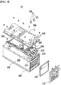
- FIG. 1 is a perspective view showing a battery pack according to one embodiment of the present disclosure
- FIG. 2 is an exploded perspective view of the battery pack of FIG. 1 .
- a battery pack 10 comprises a battery module frame 100 accommodating a battery module 200, an upper housing 400 covering an upper portion of the battery module frame 100, a busbar 500 positioned at an upper portion of the battery module frame 100 and connected to electrode leads (not shown) of the battery module 200, an internal bolt 600 positioned at an upper portion of the battery module frame 100 and connected to the busbar 500, and a terminal 700 for electrically connecting the battery pack 10 to an external device. More particularly, the terminal 700 is connected to the busbar 500 and the internal bolt 600 in order to electrically connect the battery pack 10 to an external device.
- a circuit control board 300 may be positioned between the battery module frame 100 and the upper housing 400, and the busbar 500 and the internal bolt 600 may be disposed on an upper surface of the circuit control board 300.
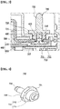
- FIG. 3 is a cross-sectional view taken along line A-A' in FIG. 1 .
- the upper housing 400 is in the form of covering the circuit control board 300 and prevents the circuit control board 300, the busbar 500 or the like from being exposed to the outside.
- at least one through opening 410 may be formed in the upper housing 400 so that the terminal 700 exposed at least partially to the outside can be electrically connected to the busbar 500 and the like.
- the internal bolt 600 protrudes upward through the through opening 410, and the terminal 700 passes through at least one through opening 410 to be connected with the busbar 500 and the internal bolt 600.
- the battery pack 10 has been designed to solve the problems as described above, and by improves the fastening structure of the terminal 700, the terminal 700 can be fixed without an additional bolt or nut, thereby simplifying the assembling structure and the manufacturing process. In addition, since the terminal can be fastened even without a separate inner space, efficient utilization of an inner space is possible.
- the structure of the terminal 700 according to one embodiment of the present disclosure will be described in detail.
- FIG. 4 is a perspective view showing the terminal 700 in FIG. 3 .
- the terminal 700 may include a nut-shaped fastening part 710 which is fastened with the internal bolt 600, a polygonal sealing part 720 which is exposed to the outside of the upper housing 400, and an upper protrusion part 730 positioned on an upper surface of the sealing part 720.
- the fastening part 710, the sealing part 720 and the upper protrusion part 730 may be integrally formed. Therefore, it is possible to implement the terminal 700 capable of sealing from an external environment and connecting to an external device only by fastening the fastening part 710 without additional members.
- the fastening part 710, the sealing part 720 and the upper protrusion part 730 will be described later in detail.
- the busbar 500 includes a through hole 510 formed in the busbar 500, and the fastening part 710 of the terminal 700 can pass through the through hole 510 of the busbar 500 as well as the through opening 410 of the upper housing 400 to be connected with the bus bar 500 and the internal bolt 600.
- the fastening part 710 of the terminal 700 forms a nut shape to be fastened with the internal bolt 600.
- the nut shape means that an indentation structure into which the internal bolt 600 can be inserted is formed in the fastening part 710 of the terminal 700, and a screw thread is formed on an inner surface of the indentation structure.
- the internal bolt 600 may include a body part 610 passing through the through hole 510 of the busbar 500 to be fastened with the fastening part 710 of the terminal 700, and an extension part 620 making contact with a lower surface of the busbar 500.
- the nut-shaped fastening part 710 is fitted to the bolt-shaped body part 610, whereby the terminal 700 can be fastened to the internal bolt 600.
- a screw thread for fastening may be formed in the body part 610 and the fastening part 710. That is, a screw thread may be formed on an outer surface of the body part 610, and the nut-shaped fastening part 710 may have a screw thread formed on an inner surface of the indentation structure into which the body part 610 is inserted.
- the extension part 620 of the internal bolt 600 is for connecting the internal bolt 600 to the busbar 500, and a lower surface of the busbar 500 and the extension part 620 are in contact and connected to each other.
- Such connection is not limited in the method as long as a physical and electrical connection between the extension 620 and the lower surface of the busbar 500 is possible, but welding is preferable. That is, the extension part 620 and the lower surface of the busbar 500 preferably have a weld-bonded structure.
- the extension part 620 of the internal bolt 600 is in contact with the lower surface of the busbar 500 by welding, etc., and at the same time, the body part 610 of the internal bolt 600 is seated on a circuit control board 300 in the state of passing through the through hole 510 of the busbar 500. Then, after the upper housing 400 is coupled, the fastening part 710 of the terminal 700 passing through the through opening 410 of the upper housing 400 is fastened with the body part 610 of the internal bolt 600, thereby completing the physical and electrical connection of the busbar 500, the internal bolt 600 and the terminal 700.
- the terminal 700 can be more concisely fastened to the busbar 500 and the internal bolt 600 without an additional bolt or nut. Further, since the terminal 700 forms a nut shape, it can be fastened to the battery pack 10 even without a separate inner space, thereby efficiently utilizing a space inside the battery pack 10.
- an outer surface of the fastening part 710 of the terminal 700 may form a stair-shaped step difference.
- a diameter X of the through hole 510 of the busbar 500 may be smaller than a diameter Y of the through opening 410 of the upper housing 400, and may be larger than a diameter Z of the body part 610 of the internal bolt 600.
- the fastening part 710 of the terminal 700 may include a first outer diameter portion 711 corresponding to the diameter X of the through hole 510 and a second outer diameter portion 712 corresponding to the diameter Y of the through opening 410, so as to be matched with the diameter X of the through hole 510 and the diameter Y of the through opening 410 while being fastened with the body part 610. That is, the first outer diameter portion 711 and the second outer diameter portion 712 of the fastening part 710 form the same diameters as the diameter X of the through hole 510 and the diameter Y of the through opening 410, respectively, which are different from each other, whereby the assembling performance of the terminal 700 can be improved when coupled to the upper housing 400 and the busbar 500.
- FIG. 5 is a cross-sectional view of a battery pack according to another embodiment of the present disclosure
- FIG. 6 is a perspective view showing a terminal in FIG. 5 .
- the battery pack according to another embodiment of the present disclosure includes an upper housing 400, a busbar 900, an internal bolt 600, and a terminal 800.
- the upper housing 400 and the internal bolt 600 form the same or similar structure as in the above-described embodiment, and thus, the description thereof will be omitted because it is repeated with the above-described contents.
- a diameter X' of the through hole 910 of the busbar 900 may be smaller than a diameter Y' of the through opening 410 of the upper housing 400 and be identical to a diameter Z' of the body part 610 of the internal bolt 600, and the fastening part 810 of the terminal 800 may include an outer diameter portion 811 corresponding to the diameter Y' of the through opening 410.
- the through hole 910 of the busbar 900 may be formed with a screw thread corresponding to an outer surface of the body part 610 on its inner surface, so as to be fastened with the body part 610 of the internal bolt 600.
- an extension part 620 of the internal bolt 600 may be in contact with a lower surface of the busbar 900 with a larger area to form a welded structure, whereby there is an effect that the coupling force between the internal bolt 600 and the busbar 900 is increased, and further, the contact resistance is reduced.
- the through hole 910 of the busbar 900 may form a screw thread corresponding to an outer surface of the body part 610 to improve the fastening performance.
- the terminal 700 may include a polygon-shaped sealing part 720 that is exposed to the outside of the upper housing 400.
- the sealing part 720 may have a structure in which it is in close contact with the upper housing 400 with a larger area than the through opening 410 of the upper housing 400, and may further include a sealing pad 721 positioned between the sealing part 720 and the upper housing 400.
- the upper housing 400 is positioned between the terminal 700 and the busbar 500. Therefore, when the terminal 700 is fastened, the terminal 700 and the upper housing 400 may be in close contact and be more firmly sealed by exhibiting a balance between force in the fastening direction due to bolt-nut coupling, and vertical drag that the upper housing 400 acts on the sealing part 720 by the force in the fastening direction.
- a plurality of bolts may be used. If there is a structural feature of the sealing part 720 as described above, the fastening of the terminal 700 may assist not only in connecting the terminal 700 to the battery pack 10, but also in fixing the upper housing 400 to the battery module frame 100.
- the degree of sealing between the terminal 700 and the upper housing 400 is improved by positioning a sealing pad 721 between the sealing part 720 and the upper housing 400, whereby it is possible to absorb a positional tolerance that may occur in assembly between machine parts, and to prevent external substances from flowing into the battery pack.
- the sealing pad 721 preferably includes at least one of an ethylene propylene diene monomer (EPDM) and a urethane material.
- the terminal 700 further includes an upper protrusion part 730 positioned on an upper surface of the sealing part 720.
- the upper protrusion part 730 is electrically connected to an external device through a connection member or the like, so that the battery cells accommodated in the battery pack can be finally connected to the external device.
- FIG. 7 is a perspective view showing the terminal 700 in FIG. 4 by changing a viewing direction.
- the terminal 700 may include a sealing part 720 having a polygonal shape, and the shape is not greatly limited, but it is preferable to include an octagonal sealing part 720.
- the sealing part 720 has a polygonal shape, particularly an octagonal shape, special equipment suitable therefor, for example, a nut driver having a shape matching the polygon should be used for the fastening process of the terminal 700, and so is the case of disassembling the terminal 700. Therefore, a normal user without such special equipment cannot easily disassemble the terminal 700.
- the battery module frame 100 for accommodating the battery module 200 may further include a port plate 110 and a side cover plate 120 disposed on the side of the battery module frame 100.
- a circuit control board 300 is mounted in the battery pack 10 and is responsible for opening and closing functions of a current flow, and protection circuit is assembled.
- a battery disconnected unit (BDU) housing may be representatively mentioned.
- the circuit control board 300 such as the battery disconnected unit (BDU) housing can cut off a power of the battery pack 10 when a current flowing into or out of the battery becomes the condition of exceeding a previously set range.
- the battery pack can be applied to various devices.
- Such devices include, but not limited to, transportation means such as an electric bicycle, an electric vehicle, and a hybrid vehicle, and the present disclosure is applicable to various devices capable of using any battery module, without being limited thereto.
Landscapes
- Chemical & Material Sciences (AREA)
- Chemical Kinetics & Catalysis (AREA)
- Electrochemistry (AREA)
- General Chemical & Material Sciences (AREA)
- Engineering & Computer Science (AREA)
- Manufacturing & Machinery (AREA)
- Microelectronics & Electronic Packaging (AREA)
- Battery Mounting, Suspending (AREA)
- Connection Of Batteries Or Terminals (AREA)
Abstract
Description
- This application claims the benefit of
Korean Patent Application No. 10-2019-0006225 filed on January 17, 2019 - The present disclosure relates to a battery pack and a device including the same, and more particularly, to a battery pack including a terminal bolt, and a device including the same.
- In modern society, as portable devices such as a mobile phone, a notebook computer, a camcorder and a digital camera has been daily used, the development of technologies in the fields related to mobile devices as described above has been activated. In addition, rechargeable secondary batteries are used as a power source for an electric vehicle (EV), a hybrid electric vehicle (HEV), a plug-in hybrid electric vehicle (P-HEV) and the like, in an attempt to solve air pollution and the like caused by existing gasoline vehicles using fossil fuel, and therefore, there is an increasing need for development of the secondary battery.
- Currently commercialized secondary batteries include a nickel cadmium battery, a nickel hydrogen battery, a nickel zinc battery, a lithium secondary battery and the like. Among them, the lithium secondary battery has come into the spotlight because they have advantages, for example, hardly exhibiting memory effects compared to nickel-based secondary batteries and thus being freely charged and discharged, and having very low self-discharge rate and high energy density.
- Such lithium secondary battery mainly uses a lithium-based oxide and a carbonaceous material as a positive electrode active material and a negative electrode active material, respectively. The lithium secondary battery includes an electrode assembly in which a positive electrode plate and a negative electrode plate respectively coated with the positive electrode active material and the negative electrode active material are disposed with a separator being interposed between them, and an exterior material, i.e., battery case, which seals and accommodates the electrode assembly together with an electrolyte.
- Generally, the lithium secondary battery may be classified into a can type secondary battery in which the electrode assembly is embedded in a metal can, and a pouch-type secondary battery in which the electrode assembly is embedded in a pouch of an aluminum laminate sheet, depending on the shape of the exterior material.
- In the case of a secondary battery used for a small-sized device, two to three battery cells are arranged, but in the case of a secondary battery used for a medium to large-sized device such as an automobile, a battery pack in which a large number of battery cells are electrically connected is used.
- This battery pack usually includes a plurality of secondary batteries, and the plurality of secondary batteries are connected to each other in series and in parallel, thereby enhancing the capacity and output. Such a battery pack includes a battery module having a plurality of secondary batteries in a stacked form, a battery module frame accommodating the battery module in the inner space, and an upper housing surrounding the battery module frame. In addition, in order to use such a battery pack, the battery pack and an external device must be electrically connected through a connecting member such as a connecting wire. For this connection, the battery pack may be provided with a terminal as a connection terminal.
- Conventionally, for the coupling of the terminal, a method of fixing the terminal using an additional bolt, a method of coupling the terminal by bonding, or the like was used. However, in the case of using the additional bolt, a sealing member is additionally required between the bolt and the terminal, which causes a problem that the structure is complicated and the cost is increased; and in the case of the bonding, there is a problem that a separate curing time is required and a sealing member varies depending on the shape of the bonding.
- Embodiments of the present disclosure have been designed to solve the problems as described above, and thus, an object thereof is to provide a battery pack in which a process can be simplified because no additional bolts or nuts are required to fix the terminal, and a terminal can be fastened even without a separate inner space, thus efficiently utilizing an inner space, and a device including the battery pack.
- A battery pack according to one embodiment of the present disclosure comprises: a battery module frame accommodating a battery module; an upper housing including at least one through opening and covering an upper portion of the battery module frame; a busbar positioned at an upper portion of the battery module frame and connected to electrode leads of the battery module; an internal bolt positioned at an upper portion of the battery module frame, protruding upward through the through opening and connected to the busbar; and a terminal passing through the through opening to be connected to the busbar and the internal bolt, wherein the terminal includes a nut-shaped fastening part which is fastened with the internal bolt.
- The busbar may include a through hole formed in the busbar, and the internal bolt may include a body part passing through the through hole to be fastened with a fastening part of the terminal, and an extension part making contact with a lower surface of the busbar.
- The diameter of the through hole is smaller than the diameter of the through opening and is larger than the diameter of the body part, and the fastening part may include a first outer diameter portion corresponding to the diameter of the through hole, and a second outer diameter portion corresponding to the diameter of the through opening.
- The diameter of the through hole is smaller than the diameter of the through opening and is identical with the diameter of the body part, and the fastening part may include an outer diameter portion corresponding to the diameter of the through opening.
- The lower surface of the busbar and the extension part may have a weld-bonded structure.
- An indentation structure into which the body part can be inserted may be formed in the nut-shaped fastening part, and a screw thread may be formed on an outer surface of the body part and an inner surface of the indentation structure.
- The battery pack may further include a circuit control board positioned between the battery module frame and the upper housing, wherein the busbar and the internal bolt may be disposed on an upper surface of the circuit control board.
- The terminal may include a polygonal sealing part exposed to the outside of the upper housing.
- The sealing part may be in close contact with the upper housing with a larger area than the through opening.
- The sealing part may include a sealing pad positioned between the sealing part and the upper housing.
- The polygon may be an octagon.
- The terminal may further include an upper protrusion part positioned on an upper surface of the sealing part.
- The fastening part, the sealing part and the upper protrusion part may be integrally formed.
- According to embodiments of the present disclosure, since the terminal can be fixed without additional bolts or nuts through the terminal having the nut-shaped fastening part, the assembling structure can be simplified and the manufacturing process thereof can be simplified.
- In addition, since the nut-shaped fastening part is fastened to a fixed internal bolt, the terminal can be fastened without a separate inner space, thereby enabling efficient utilization of an inner space.
-
-
FIG. 1 is a perspective view showing a battery pack according to one embodiment of the present disclosure. -
FIG. 2 is an exploded perspective view of the battery pack ofFIG. 1 . -
FIG. 3 is a cross-sectional view taken along line A-A' inFIG. 1 . -
FIG. 4 is a view showing a terminal inFIG. 3 . -
FIG. 5 is a cross-sectional view of a battery pack according to another embodiment of the present disclosure. -
FIG. 6 is a view showing a terminal inFIG. 5 . -
FIG. 7 is a view showing a terminal inFIG. 3 by changing a viewing direction. - Hereinafter, various embodiments of the present disclosure will be described in detail with reference to the accompanying drawings so that those skilled in the art can easily implement them. The present disclosure may be modified in various different ways, and is not limited to the embodiments set forth herein.
- Parts that are irrelevant to the description will be omitted to clearly describe the present disclosure, and like reference numerals designate like elements throughout the specification.
- Further, in the drawings, the size and thickness of each element are arbitrarily illustrated for convenience of description, and the present disclosure is not necessarily limited to those illustrated in the drawings. In the drawings, the thickness of layers, regions, etc. are exaggerated for clarity. In the drawings, for convenience of description, the thicknesses of some layers and regions are exaggerated.
- In addition, it will be understood that when an element such as a layer, film, region, or plate is referred to as being "on" or "above" another element, it can be directly on the other element or intervening elements may also be present. In contrast, when an element is referred to as being "directly on" another element, it means that other intervening elements are not present. Further, the word "on" or "above" means disposed on or below a reference portion, and does not necessarily mean being disposed on the upper side of the reference portion toward the opposite direction of gravity.
- Further, throughout the specification, when a part is referred to as "including" a certain component, it means that it can further include other components, without excluding the other components, unless otherwise stated.
-
FIG. 1 is a perspective view showing a battery pack according to one embodiment of the present disclosure, andFIG. 2 is an exploded perspective view of the battery pack ofFIG. 1 . - Referring to
FIGS. 1 and2 , abattery pack 10 according to one embodiment of the present disclosure comprises abattery module frame 100 accommodating abattery module 200, anupper housing 400 covering an upper portion of thebattery module frame 100, abusbar 500 positioned at an upper portion of thebattery module frame 100 and connected to electrode leads (not shown) of thebattery module 200, aninternal bolt 600 positioned at an upper portion of thebattery module frame 100 and connected to thebusbar 500, and aterminal 700 for electrically connecting thebattery pack 10 to an external device. More particularly, theterminal 700 is connected to thebusbar 500 and theinternal bolt 600 in order to electrically connect thebattery pack 10 to an external device. - Meanwhile, a
circuit control board 300 may be positioned between thebattery module frame 100 and theupper housing 400, and thebusbar 500 and theinternal bolt 600 may be disposed on an upper surface of thecircuit control board 300. -
FIG. 3 is a cross-sectional view taken along line A-A' inFIG. 1 . - Referring to
FIGS. 2 and3 , theupper housing 400 is in the form of covering thecircuit control board 300 and prevents thecircuit control board 300, thebusbar 500 or the like from being exposed to the outside. However, at least one through opening 410 may be formed in theupper housing 400 so that theterminal 700 exposed at least partially to the outside can be electrically connected to thebusbar 500 and the like. Theinternal bolt 600 protrudes upward through the through opening 410, and theterminal 700 passes through at least one through opening 410 to be connected with thebusbar 500 and theinternal bolt 600. - Conventionally, in order to connect a terminal as a connection terminal to the battery pack, a method of fixing the terminal using an additional bolt, a method of coupling the terminal by bonding, or the like was used. However, in the case of using the additional bolt, a sealing member is additionally required between the bolt and the terminal, which causes a problem that the structure is complicated and the cost is increased; and in the case of the bonding, the issue has been raised in that a separate curing time is required and a sealing member varies depending on the shape of components requiring the bonding. Further, since the bolt is fastened with the battery pack while facing downward, additional space for fastening was required inside the battery pack.
- The
battery pack 10 according to one embodiment of the present disclosure has been designed to solve the problems as described above, and by improves the fastening structure of the terminal 700, the terminal 700 can be fixed without an additional bolt or nut, thereby simplifying the assembling structure and the manufacturing process. In addition, since the terminal can be fastened even without a separate inner space, efficient utilization of an inner space is possible. In the following, the structure of the terminal 700 according to one embodiment of the present disclosure will be described in detail. -
FIG. 4 is a perspective view showing the terminal 700 inFIG. 3 . - Referring to
FIGS. 2 to 4 , the terminal 700 may include a nut-shapedfastening part 710 which is fastened with theinternal bolt 600, apolygonal sealing part 720 which is exposed to the outside of theupper housing 400, and anupper protrusion part 730 positioned on an upper surface of the sealingpart 720. - In particular, the
fastening part 710, the sealingpart 720 and theupper protrusion part 730 may be integrally formed. Therefore, it is possible to implement the terminal 700 capable of sealing from an external environment and connecting to an external device only by fastening thefastening part 710 without additional members. Each of thefastening part 710, the sealingpart 720 and theupper protrusion part 730 will be described later in detail. - In addition, the
busbar 500 includes a throughhole 510 formed in thebusbar 500, and thefastening part 710 of the terminal 700 can pass through the throughhole 510 of thebusbar 500 as well as the throughopening 410 of theupper housing 400 to be connected with thebus bar 500 and theinternal bolt 600. In particular, thefastening part 710 of the terminal 700 forms a nut shape to be fastened with theinternal bolt 600. The nut shape means that an indentation structure into which theinternal bolt 600 can be inserted is formed in thefastening part 710 of the terminal 700, and a screw thread is formed on an inner surface of the indentation structure. - More specifically, the
internal bolt 600 may include abody part 610 passing through the throughhole 510 of thebusbar 500 to be fastened with thefastening part 710 of the terminal 700, and anextension part 620 making contact with a lower surface of thebusbar 500. The nut-shapedfastening part 710 is fitted to the bolt-shapedbody part 610, whereby the terminal 700 can be fastened to theinternal bolt 600. A screw thread for fastening may be formed in thebody part 610 and thefastening part 710. That is, a screw thread may be formed on an outer surface of thebody part 610, and the nut-shapedfastening part 710 may have a screw thread formed on an inner surface of the indentation structure into which thebody part 610 is inserted. - The
extension part 620 of theinternal bolt 600 is for connecting theinternal bolt 600 to thebusbar 500, and a lower surface of thebusbar 500 and theextension part 620 are in contact and connected to each other. Such connection is not limited in the method as long as a physical and electrical connection between theextension 620 and the lower surface of thebusbar 500 is possible, but welding is preferable. That is, theextension part 620 and the lower surface of thebusbar 500 preferably have a weld-bonded structure. - The
extension part 620 of theinternal bolt 600 is in contact with the lower surface of thebusbar 500 by welding, etc., and at the same time, thebody part 610 of theinternal bolt 600 is seated on acircuit control board 300 in the state of passing through the throughhole 510 of thebusbar 500. Then, after theupper housing 400 is coupled, thefastening part 710 of the terminal 700 passing through the throughopening 410 of theupper housing 400 is fastened with thebody part 610 of theinternal bolt 600, thereby completing the physical and electrical connection of thebusbar 500, theinternal bolt 600 and the terminal 700. Through this coupling structure, the terminal 700 can be more concisely fastened to thebusbar 500 and theinternal bolt 600 without an additional bolt or nut. Further, since the terminal 700 forms a nut shape, it can be fastened to thebattery pack 10 even without a separate inner space, thereby efficiently utilizing a space inside thebattery pack 10. - Referring back to
FIGS. 3 and 4 , an outer surface of thefastening part 710 of the terminal 700 according to one embodiment of the present disclosure may form a stair-shaped step difference. Specifically, a diameter X of the throughhole 510 of thebusbar 500 may be smaller than a diameter Y of the throughopening 410 of theupper housing 400, and may be larger than a diameter Z of thebody part 610 of theinternal bolt 600. - The
fastening part 710 of the terminal 700 may include a firstouter diameter portion 711 corresponding to the diameter X of the throughhole 510 and a secondouter diameter portion 712 corresponding to the diameter Y of the throughopening 410, so as to be matched with the diameter X of the throughhole 510 and the diameter Y of the throughopening 410 while being fastened with thebody part 610. That is, the firstouter diameter portion 711 and the secondouter diameter portion 712 of thefastening part 710 form the same diameters as the diameter X of the throughhole 510 and the diameter Y of the throughopening 410, respectively, which are different from each other, whereby the assembling performance of the terminal 700 can be improved when coupled to theupper housing 400 and thebusbar 500. In addition, since a stair-shaped step difference is formed on the outer surface through the firstouter diameter portion 711 and the secondouter diameter portion 712, an alignment error between thebusbar 500 and theupper housing 400 can be corrected through fastening when the terminal 700 is fastened, and further, the fastening performance of the assembly structure can be improved. -
FIG. 5 is a cross-sectional view of a battery pack according to another embodiment of the present disclosure, andFIG. 6 is a perspective view showing a terminal inFIG. 5 . - Referring to
FIGS. 5 and6 , the battery pack according to another embodiment of the present disclosure includes anupper housing 400, abusbar 900, aninternal bolt 600, and a terminal 800. - Except for the terminal 800 and the
busbar 900, theupper housing 400 and theinternal bolt 600 form the same or similar structure as in the above-described embodiment, and thus, the description thereof will be omitted because it is repeated with the above-described contents. - A diameter X' of the through
hole 910 of thebusbar 900 may be smaller than a diameter Y' of the throughopening 410 of theupper housing 400 and be identical to a diameter Z' of thebody part 610 of theinternal bolt 600, and thefastening part 810 of the terminal 800 may include anouter diameter portion 811 corresponding to the diameter Y' of the throughopening 410. In addition, the throughhole 910 of thebusbar 900 may be formed with a screw thread corresponding to an outer surface of thebody part 610 on its inner surface, so as to be fastened with thebody part 610 of theinternal bolt 600. - Through the coupling structure as described above, an
extension part 620 of theinternal bolt 600 may be in contact with a lower surface of thebusbar 900 with a larger area to form a welded structure, whereby there is an effect that the coupling force between theinternal bolt 600 and thebusbar 900 is increased, and further, the contact resistance is reduced. In addition, the throughhole 910 of thebusbar 900 may form a screw thread corresponding to an outer surface of thebody part 610 to improve the fastening performance. - Referring back to
FIGS. 3 and 4 , the terminal 700 according to one embodiment of the present disclosure may include a polygon-shapedsealing part 720 that is exposed to the outside of theupper housing 400. - The sealing
part 720 may have a structure in which it is in close contact with theupper housing 400 with a larger area than the throughopening 410 of theupper housing 400, and may further include asealing pad 721 positioned between the sealingpart 720 and theupper housing 400. - Through the features as described above, it is possible to form a structure in which the
upper housing 400 is positioned between the terminal 700 and thebusbar 500. Therefore, when the terminal 700 is fastened, the terminal 700 and theupper housing 400 may be in close contact and be more firmly sealed by exhibiting a balance between force in the fastening direction due to bolt-nut coupling, and vertical drag that theupper housing 400 acts on the sealingpart 720 by the force in the fastening direction. - Moreover, when fixing the
upper housing 400 to thebattery module frame 100, a plurality of bolts may be used. If there is a structural feature of the sealingpart 720 as described above, the fastening of the terminal 700 may assist not only in connecting the terminal 700 to thebattery pack 10, but also in fixing theupper housing 400 to thebattery module frame 100. - In addition, the degree of sealing between the terminal 700 and the
upper housing 400 is improved by positioning asealing pad 721 between the sealingpart 720 and theupper housing 400, whereby it is possible to absorb a positional tolerance that may occur in assembly between machine parts, and to prevent external substances from flowing into the battery pack. Thesealing pad 721 preferably includes at least one of an ethylene propylene diene monomer (EPDM) and a urethane material. - On the other hand, the terminal 700 according to the present embodiment further includes an
upper protrusion part 730 positioned on an upper surface of the sealingpart 720. Theupper protrusion part 730 is electrically connected to an external device through a connection member or the like, so that the battery cells accommodated in the battery pack can be finally connected to the external device. -
FIG. 7 is a perspective view showing the terminal 700 inFIG. 4 by changing a viewing direction. - Referring to
FIG. 7 , the terminal 700 according to one embodiment of the present disclosure may include a sealingpart 720 having a polygonal shape, and the shape is not greatly limited, but it is preferable to include anoctagonal sealing part 720. - Since the sealing
part 720 has a polygonal shape, particularly an octagonal shape, special equipment suitable therefor, for example, a nut driver having a shape matching the polygon should be used for the fastening process of the terminal 700, and so is the case of disassembling theterminal 700. Therefore, a normal user without such special equipment cannot easily disassemble the terminal 700. - Meanwhile, referring back to
FIG. 2 , thebattery module frame 100 for accommodating thebattery module 200 may further include aport plate 110 and aside cover plate 120 disposed on the side of thebattery module frame 100. - In addition, a
circuit control board 300 is mounted in thebattery pack 10 and is responsible for opening and closing functions of a current flow, and protection circuit is assembled. As a device that can cut off a power of thebattery pack 10, a battery disconnected unit (BDU) housing may be representatively mentioned. Thecircuit control board 300 such as the battery disconnected unit (BDU) housing can cut off a power of thebattery pack 10 when a current flowing into or out of the battery becomes the condition of exceeding a previously set range. - The above-mentioned the battery pack can be applied to various devices. Such devices include, but not limited to, transportation means such as an electric bicycle, an electric vehicle, and a hybrid vehicle, and the present disclosure is applicable to various devices capable of using any battery module, without being limited thereto.
- Although the preferred embodiments of the present disclosure have been described in detail above, the scope of the present disclosure is not limited thereto, and various modifications and improvements of those skilled in the art using the basic concepts of the present disclosure defined in the following claims also belong to the scope of rights.
-
- 10: battery pack
- 100: battery module frame
- 200: battery module
- 300: circuit control board
- 400: upper housing
- 500, 900: busbar
- 600: internal bolt
- 700, 800: terminal
Claims (14)
- A battery pack comprising:a battery module frame accommodating a battery module;an upper housing including at least one through opening and covering an upper portion of the battery module frame;a busbar positioned at an upper portion of the battery module frame and connected to electrode leads of the battery module;an internal bolt positioned at an upper portion of the battery module frame, protruding upward through the through opening and connected to the busbar; anda terminal passing through the through opening to be connected to the busbar and the internal bolt,wherein the terminal includes a nut-shaped fastening part which is fastened with the internal bolt.
- The battery pack of claim 1, wherein the busbar includes a through hole formed in the busbar, and
the internal bolt includes a body part passing through the through hole to be fastened with the fastening part of the terminal, and an extension part making contact with a lower surface of the busbar. - The battery pack of claim 2, wherein the diameter of the through hole is smaller than the diameter of the through opening and is larger than the diameter of the body part, and
the fastening part includes a first outer diameter portion corresponding to the diameter of the through hole, and a second outer diameter portion corresponding to the diameter of the through opening. - The battery pack of claim 2, wherein the diameter of the through hole is smaller than the diameter of the through opening and is identical with the diameter of the body part, and
the fastening part includes an outer diameter portion corresponding to the diameter of the through opening. - The battery pack of claim 2, wherein the lower surface of the busbar and the extension part have a weld-bonded structure.
- The battery pack of claim 2, wherein an indentation structure into which the body part can be inserted is formed in the nut-shaped fastening part, and
a screw thread is formed on an outer surface of the body part and an inner surface of the indentation structure. - The battery pack of claim 1,
further comprising a circuit control board positioned between the battery module frame and the upper housing,
wherein the busbar and the internal bolt is disposed on an upper surface of the circuit control board. - The battery pack of claim 1, wherein the terminal includes a polygonal sealing part exposed to the outside of the upper housing.
- The battery pack of claim 8, wherein the sealing part is in close contact with the upper housing with a larger area than the through opening.
- The battery pack of claim 9, wherein the sealing part includes a sealing pad positioned between the sealing part and the upper housing.
- The battery pack of claim 8, wherein the polygon is an octagon.
- The battery pack of claim 8, wherein the terminal further includes an upper protrusion part positioned on an upper surface of the sealing part.
- The battery pack of claim 12, wherein the fastening part, the sealing part and the upper protrusion part are integrally formed.
- A device comprising the battery pack according to any one of claims 1 to 13 as a power source.
Applications Claiming Priority (2)
| Application Number | Priority Date | Filing Date | Title |
|---|---|---|---|
| KR1020190006225A KR102646710B1 (en) | 2019-01-17 | 2019-01-17 | Battery pack and device including the same |
| PCT/KR2020/000877 WO2020149704A1 (en) | 2019-01-17 | 2020-01-17 | Battery pack and device comprising same |
Publications (2)
| Publication Number | Publication Date |
|---|---|
| EP3843173A1 true EP3843173A1 (en) | 2021-06-30 |
| EP3843173A4 EP3843173A4 (en) | 2021-12-01 |
Family
ID=71613791
Family Applications (1)
| Application Number | Title | Priority Date | Filing Date |
|---|---|---|---|
| EP20741913.6A Pending EP3843173A4 (en) | 2019-01-17 | 2020-01-17 | BATTERY PACK AND INCLUDING DEVICE |
Country Status (6)
| Country | Link |
|---|---|
| US (1) | US12051828B2 (en) |
| EP (1) | EP3843173A4 (en) |
| JP (1) | JP7154652B2 (en) |
| KR (1) | KR102646710B1 (en) |
| CN (1) | CN112771712A (en) |
| WO (1) | WO2020149704A1 (en) |
Cited By (3)
| Publication number | Priority date | Publication date | Assignee | Title |
|---|---|---|---|---|
| EP4024592A3 (en) * | 2020-12-29 | 2022-10-12 | SK On Co., Ltd. | Battery module |
| WO2023108329A1 (en) | 2021-12-13 | 2023-06-22 | Inventus Power, Inc. | Battery pack |
| EP4307463A4 (en) * | 2021-12-29 | 2025-07-09 | Zhuhai Cosmx Power Supply Co Ltd | BATTERY |
Families Citing this family (3)
| Publication number | Priority date | Publication date | Assignee | Title |
|---|---|---|---|---|
| KR102944936B1 (en) * | 2020-10-23 | 2026-03-27 | 주식회사 엘지에너지솔루션 | Battery Module having a Thread |
| US12142989B2 (en) * | 2022-04-28 | 2024-11-12 | Garrett Transportation I Inc | Electrical connector arrangement for electronic component of turbomachine |
| WO2026108079A1 (en) * | 2024-11-20 | 2026-05-28 | 惠州亿纬锂能股份有限公司 | Immersion battery pack |
Family Cites Families (17)
| Publication number | Priority date | Publication date | Assignee | Title |
|---|---|---|---|---|
| US5021013A (en) | 1990-06-04 | 1991-06-04 | Dorothy Wiesler | Battery cable connector |
| KR101087036B1 (en) * | 2008-12-17 | 2011-11-25 | 주식회사 엘지화학 | Electrode terminal connection device and battery module assembly including the same |
| KR101147172B1 (en) | 2010-05-20 | 2012-05-25 | 에스비리모티브 주식회사 | Rechargeable battery and battery module |
| KR101589838B1 (en) | 2011-06-28 | 2016-01-28 | 쉔젠 비와이디 오토 알앤디 컴퍼니 리미티드 | Electrode terminal, cover assembly and battery comprising the cover assembly |
| EP2727166B1 (en) | 2011-06-28 | 2017-06-14 | Shenzhen BYD Auto R&D Company Limited | Cover assembly and battery comprising the same |
| KR101209935B1 (en) * | 2011-07-11 | 2012-12-10 | 기아자동차주식회사 | Fixing device of battery pack |
| JP5868265B2 (en) | 2012-05-25 | 2016-02-24 | 日立オートモティブシステムズ株式会社 | Single cells and batteries |
| US20140003016A1 (en) * | 2012-06-27 | 2014-01-02 | Aees, Inc. | Battery monitoring system |
| KR101520902B1 (en) | 2013-04-29 | 2015-05-15 | 주식회사 엘지화학 | Case for vehicle's battery pack |
| KR101737489B1 (en) * | 2014-06-05 | 2017-05-18 | 주식회사 엘지화학 | Battery pack having improved structure for supporting torque of terminal bolt |
| KR102306442B1 (en) * | 2014-08-25 | 2021-09-28 | 삼성에스디아이 주식회사 | Battery module |
| KR102281038B1 (en) * | 2014-09-19 | 2021-07-23 | 삼성에스디아이 주식회사 | Rechargeable and battery module |
| KR101948180B1 (en) * | 2015-04-30 | 2019-02-14 | 주식회사 엘지화학 | Battery pack and method for manufacturing the same |
| KR101944957B1 (en) | 2015-07-20 | 2019-02-01 | 주식회사 엘지화학 | Battery pack and vehicle comprising the same |
| KR20170012779A (en) | 2015-07-23 | 2017-02-03 | 엘에스산전 주식회사 | External connecter of battery pack |
| KR102585708B1 (en) | 2016-11-24 | 2023-10-05 | 주식회사 엘지에너지솔루션 | Battery Pack having terminal with improved sealing structure and terminal cover |
| CN207165693U (en) | 2017-09-15 | 2018-03-30 | 江苏维科新能源科技有限公司 | A kind of sealing structure of lithium battery group |
-
2019
- 2019-01-17 KR KR1020190006225A patent/KR102646710B1/en active Active
-
2020
- 2020-01-17 WO PCT/KR2020/000877 patent/WO2020149704A1/en not_active Ceased
- 2020-01-17 CN CN202080005378.4A patent/CN112771712A/en active Pending
- 2020-01-17 US US17/282,616 patent/US12051828B2/en active Active
- 2020-01-17 JP JP2021514606A patent/JP7154652B2/en active Active
- 2020-01-17 EP EP20741913.6A patent/EP3843173A4/en active Pending
Cited By (4)
| Publication number | Priority date | Publication date | Assignee | Title |
|---|---|---|---|---|
| EP4024592A3 (en) * | 2020-12-29 | 2022-10-12 | SK On Co., Ltd. | Battery module |
| WO2023108329A1 (en) | 2021-12-13 | 2023-06-22 | Inventus Power, Inc. | Battery pack |
| EP4449547A4 (en) * | 2021-12-13 | 2025-12-10 | Inventus Power Inc | BATTERY PACK |
| EP4307463A4 (en) * | 2021-12-29 | 2025-07-09 | Zhuhai Cosmx Power Supply Co Ltd | BATTERY |
Also Published As
| Publication number | Publication date |
|---|---|
| US12051828B2 (en) | 2024-07-30 |
| KR102646710B1 (en) | 2024-03-11 |
| KR20200089471A (en) | 2020-07-27 |
| JP2022501770A (en) | 2022-01-06 |
| JP7154652B2 (en) | 2022-10-18 |
| EP3843173A4 (en) | 2021-12-01 |
| US20210391632A1 (en) | 2021-12-16 |
| WO2020149704A1 (en) | 2020-07-23 |
| CN112771712A (en) | 2021-05-07 |
Similar Documents
| Publication | Publication Date | Title |
|---|---|---|
| US12051828B2 (en) | Battery pack and device including the same | |
| KR101737489B1 (en) | Battery pack having improved structure for supporting torque of terminal bolt | |
| CN106356490B (en) | Rechargeable battery and battery module including rechargeable battery | |
| EP4199208B1 (en) | Battery pack | |
| US12626982B2 (en) | Battery module, battery pack including the same and manufacturing method of the same | |
| EP4047720A1 (en) | Battery module and battery pack including same | |
| EP4195365A1 (en) | Battery module and battery pack including same | |
| US20240014526A1 (en) | Battery Module, Battery Pack Including the Same and Manufacturing Method of the Same | |
| EP4210154A1 (en) | Battery pack and device comprising same | |
| US20240258607A1 (en) | Battery pack and device including the same | |
| US20240106026A1 (en) | Battery module and battery pack including the same | |
| US12381288B2 (en) | Busbar module and method of manufacturing the same | |
| US20220399604A1 (en) | Battery module and battery pack including the same | |
| EP4181296B1 (en) | Battery pack and device including the same | |
| KR20200055336A (en) | Battery pack | |
| US11996571B2 (en) | Battery pack including upper frame having obliquely opened hinge fastened to side frame, and device including the same | |
| EP4607670A1 (en) | Battery module and battery pack including same | |
| EP4195366A1 (en) | Battery pack and device including same | |
| US20260045647A1 (en) | Battery Cell and Battery Module Including the Same | |
| EP4621977A1 (en) | Battery module and battery pack comprising same |
Legal Events
| Date | Code | Title | Description |
|---|---|---|---|
| STAA | Information on the status of an ep patent application or granted ep patent |
Free format text: STATUS: THE INTERNATIONAL PUBLICATION HAS BEEN MADE |
|
| PUAI | Public reference made under article 153(3) epc to a published international application that has entered the european phase |
Free format text: ORIGINAL CODE: 0009012 |
|
| STAA | Information on the status of an ep patent application or granted ep patent |
Free format text: STATUS: REQUEST FOR EXAMINATION WAS MADE |
|
| 17P | Request for examination filed |
Effective date: 20210322 |
|
| AK | Designated contracting states |
Kind code of ref document: A1 Designated state(s): AL AT BE BG CH CY CZ DE DK EE ES FI FR GB GR HR HU IE IS IT LI LT LU LV MC MK MT NL NO PL PT RO RS SE SI SK SM TR |
|
| REG | Reference to a national code |
Ref country code: DE Ref legal event code: R079 Free format text: PREVIOUS MAIN CLASS: H01M0002100000 Ipc: H01M0050503000 |
|
| A4 | Supplementary search report drawn up and despatched |
Effective date: 20211104 |
|
| RIC1 | Information provided on ipc code assigned before grant |
Ipc: H01R 11/26 20060101ALI20211028BHEP Ipc: H01M 10/42 20060101ALI20211028BHEP Ipc: H01M 50/211 20210101ALI20211028BHEP Ipc: H01M 50/567 20210101ALI20211028BHEP Ipc: H01M 50/566 20210101ALI20211028BHEP Ipc: H01M 50/553 20210101ALI20211028BHEP Ipc: H01M 50/519 20210101ALI20211028BHEP Ipc: H01M 50/505 20210101ALI20211028BHEP Ipc: H01M 50/503 20210101AFI20211028BHEP |
|
| RAP1 | Party data changed (applicant data changed or rights of an application transferred) |
Owner name: LG ENERGY SOLUTION LTD. |
|
| RAP3 | Party data changed (applicant data changed or rights of an application transferred) |
Owner name: LG ENERGY SOLUTION, LTD. |
|
| DAV | Request for validation of the european patent (deleted) | ||
| DAX | Request for extension of the european patent (deleted) | ||
| STAA | Information on the status of an ep patent application or granted ep patent |
Free format text: STATUS: EXAMINATION IS IN PROGRESS |
|
| 17Q | First examination report despatched |
Effective date: 20241022 |