EP3843039A1 - Automatic demarcation of anatomical structures - Google Patents
Automatic demarcation of anatomical structures Download PDFInfo
- Publication number
- EP3843039A1 EP3843039A1 EP20217185.6A EP20217185A EP3843039A1 EP 3843039 A1 EP3843039 A1 EP 3843039A1 EP 20217185 A EP20217185 A EP 20217185A EP 3843039 A1 EP3843039 A1 EP 3843039A1
- Authority
- EP
- European Patent Office
- Prior art keywords
- model data
- anatomical structure
- segment
- patient
- face
- Prior art date
- Legal status (The legal status is an assumption and is not a legal conclusion. Google has not performed a legal analysis and makes no representation as to the accuracy of the status listed.)
- Granted
Links
Images




Classifications
-
- G—PHYSICS
- G06—COMPUTING OR CALCULATING; COUNTING
- G06T—IMAGE DATA PROCESSING OR GENERATION, IN GENERAL
- G06T7/00—Image analysis
- G06T7/10—Segmentation; Edge detection
- G06T7/11—Region-based segmentation
-
- G—PHYSICS
- G06—COMPUTING OR CALCULATING; COUNTING
- G06T—IMAGE DATA PROCESSING OR GENERATION, IN GENERAL
- G06T7/00—Image analysis
- G06T7/10—Segmentation; Edge detection
-
- G—PHYSICS
- G06—COMPUTING OR CALCULATING; COUNTING
- G06T—IMAGE DATA PROCESSING OR GENERATION, IN GENERAL
- G06T19/00—Manipulating three-dimensional [3D] models or images for computer graphics
- G06T19/20—Editing of three-dimensional [3D] images, e.g. changing shapes or colours, aligning objects or positioning parts
-
- G—PHYSICS
- G06—COMPUTING OR CALCULATING; COUNTING
- G06T—IMAGE DATA PROCESSING OR GENERATION, IN GENERAL
- G06T7/00—Image analysis
- G06T7/70—Determining position or orientation of objects or cameras
-
- G—PHYSICS
- G06—COMPUTING OR CALCULATING; COUNTING
- G06T—IMAGE DATA PROCESSING OR GENERATION, IN GENERAL
- G06T7/00—Image analysis
- G06T7/70—Determining position or orientation of objects or cameras
- G06T7/73—Determining position or orientation of objects or cameras using feature-based methods
-
- G—PHYSICS
- G16—INFORMATION AND COMMUNICATION TECHNOLOGY [ICT] SPECIALLY ADAPTED FOR SPECIFIC APPLICATION FIELDS
- G16H—HEALTHCARE INFORMATICS, i.e. INFORMATION AND COMMUNICATION TECHNOLOGY [ICT] SPECIALLY ADAPTED FOR THE HANDLING OR PROCESSING OF MEDICAL OR HEALTHCARE DATA
- G16H30/00—ICT specially adapted for the handling or processing of medical images
- G16H30/20—ICT specially adapted for the handling or processing of medical images for handling medical images, e.g. DICOM, HL7 or PACS
-
- G—PHYSICS
- G16—INFORMATION AND COMMUNICATION TECHNOLOGY [ICT] SPECIALLY ADAPTED FOR SPECIFIC APPLICATION FIELDS
- G16H—HEALTHCARE INFORMATICS, i.e. INFORMATION AND COMMUNICATION TECHNOLOGY [ICT] SPECIALLY ADAPTED FOR THE HANDLING OR PROCESSING OF MEDICAL OR HEALTHCARE DATA
- G16H30/00—ICT specially adapted for the handling or processing of medical images
- G16H30/40—ICT specially adapted for the handling or processing of medical images for processing medical images, e.g. editing
-
- G—PHYSICS
- G06—COMPUTING OR CALCULATING; COUNTING
- G06T—IMAGE DATA PROCESSING OR GENERATION, IN GENERAL
- G06T2207/00—Indexing scheme for image analysis or image enhancement
- G06T2207/10—Image acquisition modality
- G06T2207/10004—Still image; Photographic image
- G06T2207/10012—Stereo images
-
- G—PHYSICS
- G06—COMPUTING OR CALCULATING; COUNTING
- G06T—IMAGE DATA PROCESSING OR GENERATION, IN GENERAL
- G06T2207/00—Indexing scheme for image analysis or image enhancement
- G06T2207/10—Image acquisition modality
- G06T2207/10072—Tomographic images
-
- G—PHYSICS
- G06—COMPUTING OR CALCULATING; COUNTING
- G06T—IMAGE DATA PROCESSING OR GENERATION, IN GENERAL
- G06T2207/00—Indexing scheme for image analysis or image enhancement
- G06T2207/10—Image acquisition modality
- G06T2207/10116—X-ray image
-
- G—PHYSICS
- G06—COMPUTING OR CALCULATING; COUNTING
- G06T—IMAGE DATA PROCESSING OR GENERATION, IN GENERAL
- G06T2207/00—Indexing scheme for image analysis or image enhancement
- G06T2207/10—Image acquisition modality
- G06T2207/10132—Ultrasound image
-
- G—PHYSICS
- G06—COMPUTING OR CALCULATING; COUNTING
- G06T—IMAGE DATA PROCESSING OR GENERATION, IN GENERAL
- G06T2207/00—Indexing scheme for image analysis or image enhancement
- G06T2207/20—Special algorithmic details
- G06T2207/20036—Morphological image processing
- G06T2207/20044—Skeletonization; Medial axis transform
-
- G—PHYSICS
- G06—COMPUTING OR CALCULATING; COUNTING
- G06T—IMAGE DATA PROCESSING OR GENERATION, IN GENERAL
- G06T2207/00—Indexing scheme for image analysis or image enhancement
- G06T2207/30—Subject of image; Context of image processing
- G06T2207/30004—Biomedical image processing
-
- G—PHYSICS
- G06—COMPUTING OR CALCULATING; COUNTING
- G06T—IMAGE DATA PROCESSING OR GENERATION, IN GENERAL
- G06T2207/00—Indexing scheme for image analysis or image enhancement
- G06T2207/30—Subject of image; Context of image processing
- G06T2207/30004—Biomedical image processing
- G06T2207/30048—Heart; Cardiac
-
- G—PHYSICS
- G06—COMPUTING OR CALCULATING; COUNTING
- G06T—IMAGE DATA PROCESSING OR GENERATION, IN GENERAL
- G06T2210/00—Indexing scheme for image generation or computer graphics
- G06T2210/41—Medical
Definitions
- the present application provides methods apparatuses, systems, and programs for improving demarcation of anatomical structures for visualization.
- cardiac disorders such as arrhythmias (e.g., atrial fibrillation)
- arrhythmias e.g., atrial fibrillation
- Procedures for treating cardiac disorders include identifying the origin of the signals causing the arrhythmia and disrupting the conductivity pathway for the erroneous signals. It is possible to interrupt the propagation of the undesirable electric signals by selectively ablating cardiac tissue.
- electrical pulmonary vein isolation from the left atrium is performed using ablation for treating atrial fibrillation. Pulmonary vein isolation, and many other minimally invasive catheterizations, require real-time visualization and mapping of the left atrium segments.
- the subject matter disclosed herein relates to a method for automatically demarcating segments of an anatomical structure and includes providing a processor having a memory, receiving and storing three-dimensional (3D) model data of an anatomical structure of a patient in the memory, generating positional information to orient 3D model data of the anatomical structure, identifying at least one segment of the 3D model data of the anatomical structure based on the positional information, demarcating the at least one identified segment of the 3D model data of the anatomical structure with an identification enhancer that visually distinguishes the at least one identified segment, and providing, for display, the 3D model data of the anatomical structure with the at least one demarcated segment.
- a processor having a memory
- receiving and storing three-dimensional (3D) model data of an anatomical structure of a patient in the memory generating positional information to orient 3D model data of the anatomical structure, identifying at least one segment of the 3D model data of the anatomical structure based on the positional information, demarc
- the method further comprises generating a skeleton axis of the 3D model data of the anatomical structure, wherein the positional information to orient the 3D model data of the anatomical structure is generated based on the skeleton axis.
- the anatomical structure is an organ of a patient.
- the anatomical structure is a chamber of a heart of the patient.
- the anatomical structure is a left atrium of a heart of the patient.
- the at least one segment comprises at least one pulmonary vein.
- the skeleton axis comprises at least one branch corresponding to at least one pulmonary vein.
- the 3D model data of the anatomical structure comprises a surface mesh.
- At least one pulmonary vein is identified by identifying all points on the surface mesh having a similar Euclidian distance from the at least one branch of the skeleton axis to the surface mesh.
- the at least one segment comprises at least one of a right superior pulmonary vein, a right inferior pulmonary vein, a left superior pulmonary vein, a left inferior pulmonary vein, and a left atrial appendage.
- the at least one segment comprises at least one of the following segments of the left atrium: a left atrial appendage, roof, a posterior wall, a septum, an anterior wall, a lateral wall, and a bottom wall.
- generating positional information to orient the anatomical structure further comprises accessing a database that stores information from known mappings of similar anatomical structures.
- generating the positional information comprises identifying at least one of a right side, left side, top side, bottom side, posterior side, and anterior side of the of the 3D model data of the anatomical structure.
- identifying at least one segment of the 3D model data of the anatomical structure further comprises generating a graphical cube about the 3D model data of the anatomical structure, the graphical cube comprising a right face, left face, top face, bottom face, posterior face, and anterior face which correspond to the respective right side, left side, top side, bottom side, posterior side, and anterior side of the of the 3D model data of the anatomical structure.
- identifying at least one segment of the 3D model data of the anatomical structure further comprises projecting at least one of the right face, left face, top face, bottom face, posterior face, and anterior face of the graphical cube onto a respective right side, left side, top side, bottom side, posterior side, and anterior side of the of the 3D model data of the anatomical structure.
- the identification enhancer comprises at least one of color, hatching, shading, and contrast.
- a display is provided to display the 3D model data of the anatomical structure with at least one demarcated segment
- the 3D model data of the anatomical structure of the patient is obtained from an imaging system.
- the imaging system comprises magnetic resonance imaging (MRI), a computed tomography (CT) scan, x-ray imaging, a rotational angiography, ultrasound imaging, three-dimensional ultrasound imaging, or a three-dimensional mapping.
- the subject matter disclosed herein relates to an apparatus for automatically demarcating segments of an anatomical structure and includes a processor comprising a memory.
- the processor is configured to receive and store three-dimensional (3D) model data of a patient's anatomical structure in the memory, generate a skeleton axis of the 3D model data of the anatomical structure, generate positional information to orient the 3D model data of the anatomical structure based on the skeleton axis, identify at least one segment of the 3D model data of the anatomical structure based on the skeleton axis and the positional information, and demarcate the at least one identified segment of the 3D model data of the anatomical structure with an identification enhancer that visually distinguishes the at least one identified segment.
- the apparatus further includes a display in communication with the processor to display the 3D model data of the anatomical structure with the at least one demarcated segment.
- the subject matter disclosed herein relates to a system for automatically demarcating segments of an anatomical structure, and includes a processor comprising a memory and a display in communication with the processor.
- the processor is configured to receive and store three-dimensional (3D) model data of a patient's anatomical structure in the memory, generate a skeleton axis of the 3D model data of the anatomical structure, generate positional information to orient the 3D model data of the anatomical structure based on the skeleton axis, identify at least one segment of the 3D model data of the anatomical structure based on the skeleton axis and the positional information, demarcate the at least one identified segment of the 3D model data of the anatomical structure with an identification enhancer that visually distinguishes the at least one identified segment, and communicate with the display to display the 3D model data of the anatomical structure with the at least one demarcated segment on the display.
- 3D three-dimensional
- the subject matter disclosed herein relates to a non-transitory computer readable recording medium storing program instructions for automatically demarcating segments of three-dimensional (3D) model data of a patient's anatomical structure by causing a computer to execute the steps of receiving and storing the three-dimensional (3D) model data of the patient's anatomical structure of a patient in the memory, generating a skeleton axis of the 3D model data of the patient's anatomical structure, generating positional information to orient 3D model data of the patient's anatomical structure based on the skeleton axis, identifying at least one segment of the 3D model data of the patient's anatomical structure based on the skeleton axis and the positional information, demarcating the at least one identified segment of the 3D model data of the patient's anatomical structure with an identification enhancer that visually distinguishes the at least one identified segment, and providing, for display, the 3D model data of the patient's anatomical structure
- a method, system, and program is provided that enables automatic demarcation of segments of anatomical structures, such as body organs, in unique patients for efficient and accurate visualization of such structures.
- model data of a patient's anatomical structure is automatically segmented and visualized on a display.
- the model data is preferably three-dimensional model data of a left atrium (LA) of an individual patient's heart. While automatic segmentation of the left atrium is described herein as an exemplary embodiment, one of ordinary skill in the art will readily understand that the method, system, and program according to the disclosed subject matter herein can be applied to automatically segment and display other organs or anatomical structures and/or portions thereof.
- a system that receives model data of a patient's anatomical structure.
- the model data can be obtained by an imaging system such as by magnetic resonance imaging (MRI), computed tomography (CT) scanning, x-ray imaging, rotational angiography, ultrasound imaging, three-dimensional ultrasound imaging, three-dimensional mapping, or any other means for two-dimensional imaging, three-dimensional imaging, and combinations of two-dimensional and three-dimensional imaging.
- the system preferably includes a processing device with a communication device that receives the model data of the patient's anatomical structure.
- the processing device Upon receiving the model data, the processing device preferably orients the anatomical structure, for example, by generating a skeleton axis of the anatomical structure, identifies readily recognizable structures, such as major veins, and incrementally enhances the segments of the anatomical structure with an identification enhancer.
- the identification enhancer preferably differentiates the individual segments and can be based on, without limitation, a color, hatching, shading, contrast, etc.
- the identification enhancer is preferably overlaid on the model data and displayed on a display.
- the system 100 preferably includes a processing device 102.
- Processing device 102 may control other components of the system 100 according to the embodiments described herein.
- the processing device 102 may include a memory 104.
- Memory 104 may comprise any suitable volatile and/or non-volatile memory, such as random-access memory (RAM), a register, cache memory, semiconductor memory devices, magnetic media such as internal hard disks and removable disks, magneto-optical media, and optical media such as CD-ROM disks, and digital versatile disks (DVDs).
- Processing device 102 preferably executes a software program and/or program stored in hardware to perform the functions required by the system 100.
- Processing device 102 may execute a software program stored in the memory 104.
- the software may be downloaded to the processing device 102 in electronic form, over a network, or may be provided on tangible media, such as optical, magnetic, or other nonvolatile memory media.
- processing device 102 may be implemented in a general-purpose computer, a special purpose computer, a processor, or a processor core.
- Suitable processors include, by way of example, a general purpose processor, a special purpose processor, a conventional processor, a digital signal processor (DSP), a plurality of microprocessors, one or more microprocessors in association with a DSP core, a controller, a microcontroller, Application Specific Integrated Circuits (ASICs), Field Programmable Gate Arrays (FPGAs) circuits, any other type of integrated circuit (IC), and/or a state machine.
- DSP digital signal processor
- ASICs Application Specific Integrated Circuits
- FPGAs Field Programmable Gate Arrays
- Such processors can be manufactured by configuring a manufacturing process using the results of processed hardware description language (HDL) instructions and other intermediary data including netlists (such instructions capable of being stored on a computer readable media).
- HDL hardware description language
- netlists such instructions capable of being stored on a computer readable media.
- the results of such processing can be mask works that are then used in a semiconductor manufacturing process to manufacture a processor which implements the methods described herein.
- processing device 102 preferably includes a communication device 106 configured to receive model data 108 of a patient's anatomical structure, such as a three-dimensional model data of an organ or portion of an organ obtained by an imaging system 107, such as by magnetic resonance imaging (MRI), computed tomography (CT) scanning, x-ray imaging, rotational angiography, ultrasound imaging, three-dimensional ultrasound imaging, three-dimensional mapping, or any other means for two-dimensional imaging, three-dimensional imaging, and combinations of two-dimensional and three-dimensional imaging.
- the communication device 106 preferably receives the model data 108 from a data transmission device 109 that can be integrated with the imaging system 107 or separate from, but in communication with, the imaging system 107.
- the communication device 106 may have a wired or wireless connection with the data transmission device 109 or may receive the model data 108 over the Internet or a network.
- the network may be any network or system generally known in the art such as an intranet, a local area network (LAN), a wide area network (WAN), a metropolitan area network (MAN), a direct connection or series of connections, a cellular telephone network, or any other network or medium capable of facilitating communication with the processing device 102.
- the network may be wired, wireless or a combination thereof. Wired connections may be implemented using Ethernet, Universal Serial Bus (USB), RJ-11 or any other wired connection generally known in the art. Wireless connections may be implemented using Wi-Fi, WiMAX, and Bluetooth, infrared, cellular networks, satellite, or any other wireless connection methodology generally known in the art.
- the model data 108 may be electronic data derived from imaging a patient's anatomical structure.
- the model data 108 is three-dimensional (3D) model data derived from an image of a patient's organ, such as a left atrium of the heart.
- the model data 108 may be stored in the memory 104.
- processing device 102 may be coupled to a display 110 to produce a visual display of the model data 108.
- the display 110 may be integrated with the processing device 102 or external to the processing device 102.
- the processing device 102 may transmit or receive information from a database 112.
- the database 112 may be a storage device (auxiliary storage device) storing various types of information determined in advance.
- the database 112 can be integral with the processing device 102, such as an internally fixed storage medium (e.g., a built-in memory, etc.) or a removable storage medium (e.g., a removable card-type memory, etc.).
- the configuration of the database 112 is not limited to such forms.
- the database 112 may be configured by an external storage device in an independent form. In this case that the database 112 is external to the processing device 102, and the processing device 102 includes a communication unit, such as communication device 106, to enable transmission and receiving of various types of information to/from the database 112.
- the database 112 stores information such as location information, orientation information, or structural information of an anatomical structure.
- the database 112 may store information relating to the orientation of an organ, such as the left atrium of the heart.
- the database 112 may also store information to identify and locate known structures within an organ, such as, without limitation, veins, chambers, walls, arteries, muscles, tendons, linings, layers, etc., that can be used to map out segments of a patient's organ, such as the left atrium.
- the processing device 102 can utilize information from the database 112 to identify readily recognizable structures, such as pulmonary veins in an image of a patient's left atrium. The location of the veins can be used to identify other segments of an organ, such as the left atrium of the heart, as will be explained in greater detail hereinafter.
- the processing device 102 preferably orients the anatomical structure, for example, by generating a surface mesh of the anatomical structure in the model data 108, such as a polygon mesh, and more preferably, such as a triangular mesh, of the anatomical structure 108 according to known methods for graphical modeling.
- the model data 108 of the anatomical structure received from the data transmission device 109 may already have a surface mesh generated thereon.
- the processing device 102 preferably generates a skeleton axis or topographical skeleton of the anatomical structure by known methods and algorithms for creating a skeleton axis, such as, and without limitation, by shrinking or collapsing the surface mesh of the model data 108 of the anatomical structure to generate a medial axis or main axis along the medial portion of the structure and any extending branch portions, such as, without limitation, veins, arteries, appendages, etc.
- known methods or algorithms for generating a skeleton axis can be utilized within the scope of the present application.
- the processing device 102 preferably orients the anatomical structure in the model data 108 by identifying three dimensional sides, such as, and without limitation, the posterior, anterior, top, bottom, right and left sides of the anatomical structure.
- the processing device can identify the posterior, anterior, top, bottom, right and left sides of the model data 108 of a patient's anatomical structure by receiving data that identifies the position of the patient's body or organ relative to the imaging system 109 when the model data 108 is generated for the patient.
- the processing device 102 can identify the posterior, anterior, top, bottom, right and left sides of the model data 108 of a patient's anatomical structure by communicating with the database 112 to compare the skeleton axis of the model data 108 with a database containing known anatomical mappings for similar anatomical structures.
- the processing device 102 relies on the skeleton axis and the orientation of the anatomical structure to automatically identify segments of the anatomical structure, and incrementally enhance the identified segments of the anatomical structure with an identification enhancer, as will be explained in detail hereinafter.
- the identification enhancer is preferably overlaid or superimposed on the model data 108 of the anatomical structure and displayed on the display 110 to visually differentiate the individual segments of the anatomical structure.
- FIG. 2 is an exemplary embodiment of a process 200 for generating and displaying an anatomical structure with segments automatically demarcated utilizing the system 100 described herein.
- FIG. 2 describes an exemplary process 200 for generating and displaying three-dimensional model data of a left atrium (LA) 300 ( FIG. 3 ) of the heart with segments automatically demarcated utilizing the system 100 described herein. More particularly, FIG.
- LA left atrium
- FIG. 2 describes an exemplary process 200 for generating and displaying a left atrium of the heart with at least the following segments automatically demarcated: right superior pulmonary vein (RSPV), right inferior pulmonary vein (RIPV), left superior pulmonary vein (LSPV), left inferior pulmonary vein (LIPV), left atrial appendage (LAA), roof, posterior wall, septum, anterior wall, lateral wall, and bottom wall.
- RSPV right superior pulmonary vein
- RIPV right inferior pulmonary vein
- LSPV left superior pulmonary vein
- LIPV left inferior pulmonary vein
- LAA left atrial appendage
- the processing device 102 receives model data of a patient's left atrium 300 via the communication device 106.
- the model data of the patient's left atrium 300 can be obtained by an imaging system, such as by magnetic resonance imaging (MRI), computed tomography (CT) scan, x-ray imaging, rotational angiography, ultrasound imaging, three-dimensional ultrasound imaging, three-dimensional mapping, or any other means for two-dimensional and three-dimensional imaging.
- FIGS. 3 and 4A illustrate exemplary embodiments of a posterior view of three-dimensional (3D) model data of the left atrium 300 of the patient's heart
- FIG. 4B illustrates an exemplary embodiment of an anterior view of the 3D model data of the left atrium 300.
- the 3D model data of the left atrium 300 can be displayed on display 110.
- the 3D model data of the left atrium 300 can be generated with a surface mesh, such as a polygon mesh, and more preferably, with a triangular mesh.
- the processing device 102 preferably orients the 3D model data of the left atrium 300.
- the processing device 102 preferably generates a skeleton axis of the 3D model data of the left atrium 300 and orients the 3D model data of the left atrium 300.
- 3 , 4A , and 4B illustrate an exemplary embodiment of a skeleton axis displayed on the 3D model data of the left atrium 300 which includes a main axis 301 and five (5) branch axes comprising: a right superior pulmonary vein (RSPV) axis 302, a right inferior pulmonary vein (RIPV) axis 304, a left superior pulmonary vein (LSPV) axis 306, a left inferior pulmonary vein (LIPV) axis 308, and a left atrial appendage (LAA) axis 310.
- the processing device 102 then preferably identifies three-dimensional orientation information of the left atrium in the 3D model data of the left atrium 300.
- the processing device 102 can establish right, left, top, bottom, posterior, and anterior sides or surfaces of the 3D model of the left atrium 300 based on the known position of the patient's heart relative to the imaging system 107 when the model data 301 is generated.
- the processing device 102 can identify the posterior, anterior, top, bottom, right and left sides of the 3D model data of the patient's left atrium 300 by communicating with the database 112 to compare the skeleton axis (301, 302, 304, 306, 308, 310) of the 3D model data of the left atrium 300 with information from the database 112 containing known mapping information for the left atrium.
- the processing device 102 preferably locates well-recognized structures in the 3D model data of the left atrium 300 based on the skeleton axis 301, 302, 304, 306, 308, 310 and the orientation information.
- the well-recognized structures include, without limitation, major veins, such as, the right superior pulmonary vein (RSPV) 312, right inferior pulmonary vein (RIPV) 314, left superior pulmonary vein (LSPV) 316, left inferior pulmonary vein (LIPV) 318, and the left atrial appendage (LAA) 320 as shown in FIGS 4A and 4B .
- the pulmonary veins 312, 314, 316, 318 and LAA 320 can be identified by orienting the 3D model data of the left atrium 300 in a posterior view, and identifying the two major branches of the skeleton axis 302, 304 at the right side to be the RSPV 312 and RIPV 314, wherein the upper branch, or RSPV axis 302, of the skeleton axis is used to identify the RSPV 312 and the lower branch, or RIPV axis 304, of the skeleton axis is used to identify the RIPV 314.
- the three major branches of the skeleton axis 306, 308, 310 at the left side of the 3D model data of the left atrium 300 are used to identify the LSPV 316, LIPV 318, and LAA 320, wherein the upper branch, or LSPV axis 306, of the skeleton axis is used to identify the LSPV 316, the lower branch, or LIPV axis 308, of the skeleton axis is used to identify the LIPV 318, and the middle branch, or LAA axis 310, of the skeleton axis is used to identify the LAA 320.
- FIG. 4B illustrates an exemplary embodiment of an anterior view of the 3D model data of the left atrium 300 showing the identified pulmonary veins 312, 314, 316, 318 and LAA 320.
- the processing device 102 can orient the 3D model data of the left atrium 300 without generating a skeleton axis of the 3D model data of the left atrium 300 as described in steps 204 and 206 of FIG. 2 .
- the processing device 102 can identify the RSPV 312, RIPV 314, LSPV 316, LIPV 318, and the left atrial appendage LAA 320 by communicating with the database 112 to compare the 3D model data of the left atrium 300 with information from the database 112 containing known mapping information for the left atrium.
- the processing device 102 preferably establishes where the pulmonary veins 312, 314, 316, 318, and LAA 320 integrate with the body 321 of the left atrium and demarcates the pulmonary veins 312, 314, 316, 318, and LAA 320 in the 3D model data of the left atrium with an identification enhancer as shown in FIGS. 4A and 4B .
- the processing device 102 in order to demarcate the pulmonary veins 312, 314, 316, 318 and the LAA 320, the processing device 102 preferably identifies branch axis pairs of the skeleton axis having a common branch point from the main axis 301, such as: RSPV axis 302 _ RIPV axis 304; LSPV axis 306 - LIPV axis 308; and LSPV axis 306 - LAA axis 310. For each identified branch axis pair, the processing device 102 identifies all points P a on the surface mesh of the 3D model data of the left atrium 300 having a similar Euclidian distance from the respective branch axis pair to the surface mesh.
- the points P a on the surface mesh for each of the pulmonary veins 312, 314, 316, 318 and LAA 320 that are closest to a center point 311 of the main axis 301 define a boundary P b between the body 321 of the left atrium and the respective pulmonary veins 312, 314, 316, 318 and LAA 320.
- the boundary P b preferably coincides with the common branch point between the branch axis pairs and the main axis 301.
- the points P a on the surface mesh of the 3D model data of the left atrium 300 are used to demarcate the pulmonary veins 312, 314, 316, 318 and LAA 320 within the respective boundaries P b .
- the processing device 102 preferably superimposes an identification enhancer on each of the identified pulmonary veins 312, 314, 316, 318, and LAA 320 in the 3D model data to differentiate them for demarcation and visual recognition.
- the identification enhancer can be, without limitation, a color, hatching, shading, contrast, or any other means to visually distinguish structures.
- the identification enhancer is preferably superimposed on the 3D model data of the left atrium 300 and displayed on the display 110.
- FIGS. 4A and 4B illustrates exemplary embodiments in which an identification enhancer is superimposed on segments of the 3D model data of the left atrium, including the RSPV 312, RIPV 314, LSPV 316, LIPV 318, and LAA 320. As described herein, the identification enhancer visually distinguishes the pulmonary veins 312, 314, 316, 318 and LAA 320 from one another.
- the processing device 102 preferably generates a graphical cube 500 about the 3D model data of the left atrium 300 to assist with the process of segment demarcation as shown in FIGS. 5-12 .
- the graphical cube 500 includes posterior 502, anterior 504, top 506, bottom 508, right 510, and left 512 faces. The process of segment demarcation is further described in steps 212 through 222 of FIG. 2 .
- the graphical cube is preferably generated by creating a rectangle for the top face 506 in which the rectangle's vertices are positioned adjacent the RSPV 312, RIPV 314, LSPV 316, and LIPV 318.
- the top face 506 is pulled down to form a 3D graphical cube 500 in which the bottom face 508 is adjacent the lowest point of the 3D model data of the left atrium 300 (see FIG. 6 ).
- the processing device 102 identifies the roof segment 322 of the left atrium in the 3D model data of the left atrium 300.
- the processing device 102 preferably identifies the roof segment 322 by orienting a surface in the surface mesh of the 3D model data of the lower atrium 300 between the boundaries P b for each of the RSPV 312, RIPV 314, LSPV 316, and LIPV 318, respectively, adjacent a top face 506 of the graphical cube 500.
- the processing device 102 identifies the roof segment 322 of the left atrium in the 3D model data of the left atrium 300.
- the processing device 102 preferably identifies the roof segment 322 by orienting a surface in the surface mesh of the 3D model data of the lower atrium 300 between the boundaries P b for each of the RSPV 312, RIPV 314, LSPV 316, and LIPV 318, respectively, adjacent a top face 506 of the graphical cube 500.
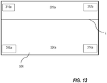
- the relative locations of the RSPV 312, RIPV 314, LSPV 316, LIPV 318 preferably form corresponding corner points 312a, 314a, 316a, 318a in the top face 506 of the graphical cube 500.
- the processing device divides the top face 506 by generating line L parallel to an edge formed by corners 312a-316a and an edge formed by corners 314a-318a.
- Line L is preferably generated in a manner to divide a surface area representing the roof segment 322a from a surface area representing the posterior wall segment 324a in the top face 506 of the graphical cube 500 based on predetermined surface areas from known 3D mappings of roof segments relative to the posterior walls.
- the processing device 102 can access the database 112 to obtain the predetermined surface areas.
- the top face 506 of the graphical cube is divided by Line L such that the surface area representing the roof segment 322a is smaller than the surface area representing the posterior wall 324a.
- the surface area representing the roof segment 322a is approximately 20%-30% of the surface area of the top face 506 and the surface area representing the posterior wall 324a is approximately 70%-80% of the surface area of the top face 506.
- the foregoing percentages of the surface area of the top face 506 can be modified based on the particular anatomical structure or organ in the subject model data 1098.
- the smaller surface area 322a of the top face 506 of the graphical cube 500 is projected onto the surface mesh of the 3D model of the lower atrium 300 to define the roof segment 322.
- the roof segment 322 is preferably denoted with an identification enhancer, such as a color, hatching, shading, contrast, etc., for visual identification of the roof segment 322 on the display 110 as shown in FIGS. 6 , 7 , 8 , and 10 .
- the processing device 102 identifies the posterior wall segment 324 of the left atrium in the 3D model data of the left atrium 300.
- the processing device 102 preferably identifies the posterior wall segment 324 by identifying a segment of the left atrium adjacent the roof segment 322 and between the boundaries P b for the RSPV 312, RIPV 314, LSPV 316, and LIPV 318 using the process described above with respect to identification of the roof segment 322.
- the larger surface area 324a of the top face 506 of the graphical cube 500 is projected onto the surface mesh of the 3D model of the lower atrium 300 to define the posterior wall segment 324.
- the posterior wall segment 324 is preferably denoted with an identification enhancer for visual identification of the posterior wall segment 324 on the display 110 as shown in FIGS. 6-8 , 10 , and 12 .
- the processing device 102 identifies the septum segment 326 of the left atrium in the 3D model data of the left atrium 300.
- the processing device 102 preferably identifies the septum segment 326 by projecting the right face 510 of the graphical cube 500 onto the surface mesh of the 3D model of the lower atrium 300 and identifying a segment of the left atrium adjacent the RSPV 312, RIPV 314 as the septum segment 326.
- the septum segment 326 is preferably denoted with an identification enhancer for visual identification of the septum segment 326 on the display 110 as shown in FIGS. 6-12 .
- the processing device 102 identifies the anterior wall segment 328 of the left atrium in the 3D model data of the left atrium 300.
- the processing device 102 preferably identifies the anterior wall segment 328 by projecting the anterior face 504 of the graphical cube 500 onto the surface mesh of the 3D model of the lower atrium 300 and identifying a segment of the left atrium adjacent the RSPV 312, LAA 320, roof segment 322, and septum segment 326 as the anterior wall segment.
- the anterior wall segment 328 is preferably denoted with an identification enhancer for visual identification of the anterior wall segment 328 on the display 110 as shown in FIGS. 7 , 9, and 10 .
- the processing device 102 identifies the lateral wall segment 330 of the left atrium in the 3D model data of the left atrium 300.
- the processing device 102 preferably identifies the lateral wall segment 330 by projecting the left face 512 of the graphical cube 500 onto the surface mesh of the 3D model of the lower atrium 300 and identifying a segment of the left atrium adjacent the LSPV 316, LIPV 318, and LAA 320 and the anterior wall segment 328 as the lateral wall segment 330.
- the lateral wall segment 330 is preferably denoted with an identification enhancer for visual identification of the lateral wall segment 330 on the display 110 as shown in FIGS. 6-8 , 10 , and 12 .
- the processing device 102 identifies the bottom wall segment 332 of the left atrium in the 3D model data of the left atrium 300.
- the processing device 102 preferably identifies the bottom wall segment 332 by projecting the bottom face 508 of the graphical cube 500 onto the surface mesh of the 3D model of the lower atrium 300 and identifying a segment of the left atrium adjacent the RIPV 316, LIPV 318, LAA 320, posterior wall segment 324, anterior wall segment 328, septum segment 326, and lateral wall segment 330 as the bottom wall segment 332.
- the bottom wall segment 332 is preferably denoted with an identification enhancer for visual identification of the bottom wall segment 332 on the display 110.
- step 222 the processing device expands the boundaries of each segment until contact is made with other segments to fill the 3D model data of the left atrium 300 with identification enhancers to visually distinguish the demarcated segments.
- the segmented 3D model data of the left atrium 300 is preferably displayed on the display 110 showing different identification enhancers to visually distinguish the demarcated segments.
- different identification enhancers such as, for example, different colors, can be used to visually distinguish the various identified structures.
- each, or any of steps 204-224 of process 200 can be incrementally displayed on the display 110 during each respective step of the process 200.
- steps 204-224 of process 200 can be incrementally performed in any preferred order, and that certain steps of process 200 can be eliminated or additional process steps can be added to identify other segments of the left atrium not specifically mentioned herein.
- FIGS. 2-13 and the disclosure herein relate an exemplary process 200 for generating and displaying a left atrium (LA) of the heart with segments automatically demarcated utilizing the system 100 described herein, one of ordinary skill in the art will readily understand that the disclosed process can be applied to automatically segment and display other organs or anatomical structures.
- LA left atrium
- the subject matter disclosed herein for automatic demarcation of an anatomical structure reduces the time involved to segment anatomical structures as compared to conventional techniques which require manual segmentation, and it provides more accurate and predictable data by minimizing any human error.
- non-transitory computer-readable storage mediums include a ROM, a random access memory (RAM), a register, cache memory, semiconductor memory devices, magnetic media such as internal hard disks and removable disks, magneto-optical media, and optical media such as CD-ROM disks, and digital versatile disks (DVDs).
Landscapes
- Engineering & Computer Science (AREA)
- Theoretical Computer Science (AREA)
- General Physics & Mathematics (AREA)
- Physics & Mathematics (AREA)
- Health & Medical Sciences (AREA)
- Computer Vision & Pattern Recognition (AREA)
- General Health & Medical Sciences (AREA)
- Primary Health Care (AREA)
- Public Health (AREA)
- Medical Informatics (AREA)
- Epidemiology (AREA)
- Radiology & Medical Imaging (AREA)
- Nuclear Medicine, Radiotherapy & Molecular Imaging (AREA)
- Computer Hardware Design (AREA)
- Computer Graphics (AREA)
- Architecture (AREA)
- General Engineering & Computer Science (AREA)
- Software Systems (AREA)
- Apparatus For Radiation Diagnosis (AREA)
- Magnetic Resonance Imaging Apparatus (AREA)
- Measuring And Recording Apparatus For Diagnosis (AREA)
- Image Analysis (AREA)
- Laser Surgery Devices (AREA)
Abstract
Description
- This application claims the benefit of
U.S. Provisional Patent Application Serial No. 62/954,194, filed on December 27, 2019 - The present application provides methods apparatuses, systems, and programs for improving demarcation of anatomical structures for visualization.
- There is a need to clearly identify segments of anatomical structures of individual patients, such as body organs, for medical treatment and investigation, clinical workflows, and research purposes. Because anatomical structures, such as the chambers of the heart, are typically unique to an individual, variations between corresponding anatomical structures in different individuals has inhibited the use of automated tools to accurately identify the different segments of such structures in a quick and efficient manner.
- Conventionally, identification of segments of anatomical structures, such as the left atrium, is manually performed by a medical professional or researcher. However, such manual identification is time consuming, inefficient, and can require the use of special 3D editing software.
- Quick and automated identification of segments of anatomical structures can be critical for treating certain conditions. For example, cardiac disorders, such as arrhythmias (e.g., atrial fibrillation), are associated with abnormal conductivity of heart tissue. Procedures for treating cardiac disorders include identifying the origin of the signals causing the arrhythmia and disrupting the conductivity pathway for the erroneous signals. It is possible to interrupt the propagation of the undesirable electric signals by selectively ablating cardiac tissue. For example, electrical pulmonary vein isolation from the left atrium is performed using ablation for treating atrial fibrillation. Pulmonary vein isolation, and many other minimally invasive catheterizations, require real-time visualization and mapping of the left atrium segments.
- There exists a need in the art to accurately identify different segments of anatomical structures that are unique to each individual in an automated manner in order to reduce the time and human error involved with such identification.
- Methods, apparatuses, systems, and programs for improving demarcation of anatomical structures for visualization are described herein.
- In accordance with one aspect, the subject matter disclosed herein relates to a method for automatically demarcating segments of an anatomical structure and includes providing a processor having a memory, receiving and storing three-dimensional (3D) model data of an anatomical structure of a patient in the memory, generating positional information to orient 3D model data of the anatomical structure, identifying at least one segment of the 3D model data of the anatomical structure based on the positional information, demarcating the at least one identified segment of the 3D model data of the anatomical structure with an identification enhancer that visually distinguishes the at least one identified segment, and providing, for display, the 3D model data of the anatomical structure with the at least one demarcated segment.
- In accordance with another aspect, the method further comprises generating a skeleton axis of the 3D model data of the anatomical structure, wherein the positional information to orient the 3D model data of the anatomical structure is generated based on the skeleton axis.
- In accordance with another aspect, the anatomical structure is an organ of a patient. In accordance with still another aspect, the anatomical structure is a chamber of a heart of the patient. In accordance with still another aspect, the anatomical structure is a left atrium of a heart of the patient.
- In accordance with yet another aspect, the at least one segment comprises at least one pulmonary vein. In accordance with yet another aspect, the skeleton axis comprises at least one branch corresponding to at least one pulmonary vein.
- In accordance with yet another aspect, the 3D model data of the anatomical structure comprises a surface mesh.
- In accordance with yet another aspect, at least one pulmonary vein is identified by identifying all points on the surface mesh having a similar Euclidian distance from the at least one branch of the skeleton axis to the surface mesh.
- In accordance with yet another aspect, the at least one segment comprises at least one of a right superior pulmonary vein, a right inferior pulmonary vein, a left superior pulmonary vein, a left inferior pulmonary vein, and a left atrial appendage. In accordance with yet another aspect, the at least one segment comprises at least one of the following segments of the left atrium: a left atrial appendage, roof, a posterior wall, a septum, an anterior wall, a lateral wall, and a bottom wall.
- In accordance with yet another aspect, generating positional information to orient the anatomical structure further comprises accessing a database that stores information from known mappings of similar anatomical structures. In accordance with yet another aspect, generating the positional information comprises identifying at least one of a right side, left side, top side, bottom side, posterior side, and anterior side of the of the 3D model data of the anatomical structure.
- In accordance with yet another aspect, identifying at least one segment of the 3D model data of the anatomical structure further comprises generating a graphical cube about the 3D model data of the anatomical structure, the graphical cube comprising a right face, left face, top face, bottom face, posterior face, and anterior face which correspond to the respective right side, left side, top side, bottom side, posterior side, and anterior side of the of the 3D model data of the anatomical structure.
- In accordance with yet another aspect, identifying at least one segment of the 3D model data of the anatomical structure further comprises projecting at least one of the right face, left face, top face, bottom face, posterior face, and anterior face of the graphical cube onto a respective right side, left side, top side, bottom side, posterior side, and anterior side of the of the 3D model data of the anatomical structure.
- In accordance with yet another aspect, the identification enhancer comprises at least one of color, hatching, shading, and contrast.
- In accordance with yet another aspect, a display is provided to display the 3D model data of the anatomical structure with at least one demarcated segment
- In accordance with yet another aspect, the 3D model data of the anatomical structure of the patient is obtained from an imaging system. In an aspect, the imaging system comprises magnetic resonance imaging (MRI), a computed tomography (CT) scan, x-ray imaging, a rotational angiography, ultrasound imaging, three-dimensional ultrasound imaging, or a three-dimensional mapping.
- In accordance with yet another aspect, the subject matter disclosed herein relates to an apparatus for automatically demarcating segments of an anatomical structure and includes a processor comprising a memory. The processor is configured to receive and store three-dimensional (3D) model data of a patient's anatomical structure in the memory, generate a skeleton axis of the 3D model data of the anatomical structure, generate positional information to orient the 3D model data of the anatomical structure based on the skeleton axis, identify at least one segment of the 3D model data of the anatomical structure based on the skeleton axis and the positional information, and demarcate the at least one identified segment of the 3D model data of the anatomical structure with an identification enhancer that visually distinguishes the at least one identified segment. The apparatus further includes a display in communication with the processor to display the 3D model data of the anatomical structure with the at least one demarcated segment.
- In accordance with yet another aspect, the subject matter disclosed herein relates to a system for automatically demarcating segments of an anatomical structure, and includes a processor comprising a memory and a display in communication with the processor. The processor is configured to receive and store three-dimensional (3D) model data of a patient's anatomical structure in the memory, generate a skeleton axis of the 3D model data of the anatomical structure, generate positional information to orient the 3D model data of the anatomical structure based on the skeleton axis, identify at least one segment of the 3D model data of the anatomical structure based on the skeleton axis and the positional information, demarcate the at least one identified segment of the 3D model data of the anatomical structure with an identification enhancer that visually distinguishes the at least one identified segment, and communicate with the display to display the 3D model data of the anatomical structure with the at least one demarcated segment on the display.
- In accordance with yet another aspect, the subject matter disclosed herein relates to a non-transitory computer readable recording medium storing program instructions for automatically demarcating segments of three-dimensional (3D) model data of a patient's anatomical structure by causing a computer to execute the steps of receiving and storing the three-dimensional (3D) model data of the patient's anatomical structure of a patient in the memory, generating a skeleton axis of the 3D model data of the patient's anatomical structure, generating positional information to orient 3D model data of the patient's anatomical structure based on the skeleton axis, identifying at least one segment of the 3D model data of the patient's anatomical structure based on the skeleton axis and the positional information, demarcating the at least one identified segment of the 3D model data of the patient's anatomical structure with an identification enhancer that visually distinguishes the at least one identified segment, and providing, for display, the 3D model data of the patient's anatomical structure with the at least one demarcated segment.
- A more detailed understanding can be had from the following description, given by way of example in conjunction with the accompanying drawings wherein:
-
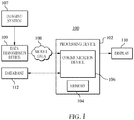
FIG. 1 is a schematic representation of an apparatus and system for generating and displaying model data of an anatomical structure with segments automatically demarcated in accordance with the present invention. -
FIG. 2 is a flowchart illustrating an exemplary embodiment for generating and displaying model data of a left atrium with its segments automatically demarcated in accordance with the present invention. -
FIG. 3 is an exemplary embodiment of a posterior view of three-dimensional model data of a left atrium with a skeleton axis displayed in accordance with the present invention. -
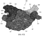
FIG. 4A is an exemplary embodiment of another posterior view of the three-dimensional model data of the left atrium which is slightly rotated relative toFIG. 3 to show more of the bottom wall and showing the pulmonary veins and left atrial appendage demarcated with an identification enhancer in accordance with the present invention. -
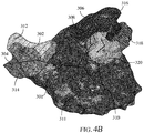
FIG. 4B is an exemplary embodiment of an anterior view of the three-dimensional model data of the left atrium showing the pulmonary veins and left atrial appendage demarcated with an identification enhancer in accordance with the present invention. -
FIG. 5 is an exemplary embodiment of a posterior view of the three-dimensional model data of the left atrium within a graphical cube according to an exemplary embodiment of the invention showing with the skeleton axis displayed. -
FIG. 6 is an exemplary embodiment of a posterior side view of the three-dimensional model data of the left atrium within a graphical cube according to an exemplary embodiment of the invention showing the atrial segments demarcated with an identification enhancer. -
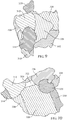
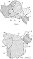
FIG. 7 is an anterior side view of the three-dimensional model data of the left atrium ofFIG 6 without the graphical cube displayed in accordance with the present invention. -
FIG. 8 is a top side view of the three-dimensional model data of the left atrium ofFIG 6 in accordance with the present invention. -
FIG. 9 is a right side view of the three-dimensional model data of the left atrium ofFIG 6 in accordance with the present invention. -
FIG. 10 is another anterior side view of the three-dimensional model data of the left atrium ofFIG 6 in accordance with the present invention. -
FIG. 11 is a left side view of the three-dimensional model data of the left atrium ofFIG 6 in accordance with the present invention. -
FIG. 12 is a bottom side view of the three-dimensional model data of the left atrium ofFIG 6 in accordance with the present invention. -
FIG. 13 is a plan view of a top face of the graphical cube showing an exemplary division of the surface area of the top face in accordance with the present invention. - A method, system, and program is provided that enables automatic demarcation of segments of anatomical structures, such as body organs, in unique patients for efficient and accurate visualization of such structures.
- In an exemplary embodiment, model data of a patient's anatomical structure is automatically segmented and visualized on a display. The model data is preferably three-dimensional model data of a left atrium (LA) of an individual patient's heart. While automatic segmentation of the left atrium is described herein as an exemplary embodiment, one of ordinary skill in the art will readily understand that the method, system, and program according to the disclosed subject matter herein can be applied to automatically segment and display other organs or anatomical structures and/or portions thereof.
- According to exemplary embodiments disclosed herein, a system is provided that receives model data of a patient's anatomical structure. The model data can be obtained by an imaging system such as by magnetic resonance imaging (MRI), computed tomography (CT) scanning, x-ray imaging, rotational angiography, ultrasound imaging, three-dimensional ultrasound imaging, three-dimensional mapping, or any other means for two-dimensional imaging, three-dimensional imaging, and combinations of two-dimensional and three-dimensional imaging. The system preferably includes a processing device with a communication device that receives the model data of the patient's anatomical structure. Upon receiving the model data, the processing device preferably orients the anatomical structure, for example, by generating a skeleton axis of the anatomical structure, identifies readily recognizable structures, such as major veins, and incrementally enhances the segments of the anatomical structure with an identification enhancer. The identification enhancer preferably differentiates the individual segments and can be based on, without limitation, a color, hatching, shading, contrast, etc. The identification enhancer is preferably overlaid on the model data and displayed on a display.
- Referring to
FIG. 1 , anexemplary system 100 that enables automatic demarcation of segments of an individual patient's anatomical structures is provided. Thesystem 100 preferably includes aprocessing device 102.Processing device 102 may control other components of thesystem 100 according to the embodiments described herein. According to an exemplary embodiment, theprocessing device 102 may include amemory 104.Memory 104 may comprise any suitable volatile and/or non-volatile memory, such as random-access memory (RAM), a register, cache memory, semiconductor memory devices, magnetic media such as internal hard disks and removable disks, magneto-optical media, and optical media such as CD-ROM disks, and digital versatile disks (DVDs).Processing device 102 preferably executes a software program and/or program stored in hardware to perform the functions required by thesystem 100.Processing device 102 may execute a software program stored in thememory 104. The software may be downloaded to theprocessing device 102 in electronic form, over a network, or may be provided on tangible media, such as optical, magnetic, or other nonvolatile memory media. - According to an exemplary embodiment,
processing device 102 may be implemented in a general-purpose computer, a special purpose computer, a processor, or a processor core. Suitable processors include, by way of example, a general purpose processor, a special purpose processor, a conventional processor, a digital signal processor (DSP), a plurality of microprocessors, one or more microprocessors in association with a DSP core, a controller, a microcontroller, Application Specific Integrated Circuits (ASICs), Field Programmable Gate Arrays (FPGAs) circuits, any other type of integrated circuit (IC), and/or a state machine. Such processors can be manufactured by configuring a manufacturing process using the results of processed hardware description language (HDL) instructions and other intermediary data including netlists (such instructions capable of being stored on a computer readable media). The results of such processing can be mask works that are then used in a semiconductor manufacturing process to manufacture a processor which implements the methods described herein. - According to an exemplary embodiment,
processing device 102 preferably includes acommunication device 106 configured to receivemodel data 108 of a patient's anatomical structure, such as a three-dimensional model data of an organ or portion of an organ obtained by animaging system 107, such as by magnetic resonance imaging (MRI), computed tomography (CT) scanning, x-ray imaging, rotational angiography, ultrasound imaging, three-dimensional ultrasound imaging, three-dimensional mapping, or any other means for two-dimensional imaging, three-dimensional imaging, and combinations of two-dimensional and three-dimensional imaging. Thecommunication device 106 preferably receives themodel data 108 from adata transmission device 109 that can be integrated with theimaging system 107 or separate from, but in communication with, theimaging system 107. Thecommunication device 106 may have a wired or wireless connection with thedata transmission device 109 or may receive themodel data 108 over the Internet or a network. The network may be any network or system generally known in the art such as an intranet, a local area network (LAN), a wide area network (WAN), a metropolitan area network (MAN), a direct connection or series of connections, a cellular telephone network, or any other network or medium capable of facilitating communication with theprocessing device 102. The network may be wired, wireless or a combination thereof. Wired connections may be implemented using Ethernet, Universal Serial Bus (USB), RJ-11 or any other wired connection generally known in the art. Wireless connections may be implemented using Wi-Fi, WiMAX, and Bluetooth, infrared, cellular networks, satellite, or any other wireless connection methodology generally known in the art. - According to an exemplary embodiment, the
model data 108 may be electronic data derived from imaging a patient's anatomical structure. In an exemplary embodiment, themodel data 108 is three-dimensional (3D) model data derived from an image of a patient's organ, such as a left atrium of the heart. Upon receipt of themodel data 108 by the processing device, themodel data 108 may be stored in thememory 104. - According to an exemplary embodiment,
processing device 102 may be coupled to adisplay 110 to produce a visual display of themodel data 108. Thedisplay 110 may be integrated with theprocessing device 102 or external to theprocessing device 102. - According to an exemplary embodiment, the
processing device 102 may transmit or receive information from adatabase 112. Thedatabase 112 may be a storage device (auxiliary storage device) storing various types of information determined in advance. In an exemplary embodiment, thedatabase 112 can be integral with theprocessing device 102, such as an internally fixed storage medium (e.g., a built-in memory, etc.) or a removable storage medium (e.g., a removable card-type memory, etc.). However, the configuration of thedatabase 112 is not limited to such forms. In another exemplary embodiment, thedatabase 112 may be configured by an external storage device in an independent form. In this case that thedatabase 112 is external to theprocessing device 102, and theprocessing device 102 includes a communication unit, such ascommunication device 106, to enable transmission and receiving of various types of information to/from thedatabase 112. - According to an exemplary embodiment, the
database 112 stores information such as location information, orientation information, or structural information of an anatomical structure. For example, thedatabase 112 may store information relating to the orientation of an organ, such as the left atrium of the heart. Thedatabase 112, may also store information to identify and locate known structures within an organ, such as, without limitation, veins, chambers, walls, arteries, muscles, tendons, linings, layers, etc., that can be used to map out segments of a patient's organ, such as the left atrium. In an exemplary embodiment, theprocessing device 102 can utilize information from thedatabase 112 to identify readily recognizable structures, such as pulmonary veins in an image of a patient's left atrium. The location of the veins can be used to identify other segments of an organ, such as the left atrium of the heart, as will be explained in greater detail hereinafter. - In an exemplary embodiment, the
processing device 102 preferably orients the anatomical structure, for example, by generating a surface mesh of the anatomical structure in themodel data 108, such as a polygon mesh, and more preferably, such as a triangular mesh, of theanatomical structure 108 according to known methods for graphical modeling. Alternatively, themodel data 108 of the anatomical structure received from thedata transmission device 109 may already have a surface mesh generated thereon. - In an exemplary embodiment, the
processing device 102 preferably generates a skeleton axis or topographical skeleton of the anatomical structure by known methods and algorithms for creating a skeleton axis, such as, and without limitation, by shrinking or collapsing the surface mesh of themodel data 108 of the anatomical structure to generate a medial axis or main axis along the medial portion of the structure and any extending branch portions, such as, without limitation, veins, arteries, appendages, etc. One of ordinary skill in the art will recognize that other known methods or algorithms for generating a skeleton axis can be utilized within the scope of the present application. - In an exemplary embodiment, the
processing device 102 preferably orients the anatomical structure in themodel data 108 by identifying three dimensional sides, such as, and without limitation, the posterior, anterior, top, bottom, right and left sides of the anatomical structure. In a non-limiting example, the processing device can identify the posterior, anterior, top, bottom, right and left sides of themodel data 108 of a patient's anatomical structure by receiving data that identifies the position of the patient's body or organ relative to theimaging system 109 when themodel data 108 is generated for the patient. Alternatively, theprocessing device 102 can identify the posterior, anterior, top, bottom, right and left sides of themodel data 108 of a patient's anatomical structure by communicating with thedatabase 112 to compare the skeleton axis of themodel data 108 with a database containing known anatomical mappings for similar anatomical structures. - In an exemplary embodiment, the
processing device 102 relies on the skeleton axis and the orientation of the anatomical structure to automatically identify segments of the anatomical structure, and incrementally enhance the identified segments of the anatomical structure with an identification enhancer, as will be explained in detail hereinafter. The identification enhancer is preferably overlaid or superimposed on themodel data 108 of the anatomical structure and displayed on thedisplay 110 to visually differentiate the individual segments of the anatomical structure. -
FIG. 2 is an exemplary embodiment of aprocess 200 for generating and displaying an anatomical structure with segments automatically demarcated utilizing thesystem 100 described herein. In particular,FIG. 2 describes anexemplary process 200 for generating and displaying three-dimensional model data of a left atrium (LA) 300 (FIG. 3 ) of the heart with segments automatically demarcated utilizing thesystem 100 described herein. More particularly,FIG. 2 describes anexemplary process 200 for generating and displaying a left atrium of the heart with at least the following segments automatically demarcated: right superior pulmonary vein (RSPV), right inferior pulmonary vein (RIPV), left superior pulmonary vein (LSPV), left inferior pulmonary vein (LIPV), left atrial appendage (LAA), roof, posterior wall, septum, anterior wall, lateral wall, and bottom wall. - At
step 202 ofFIG. 2 , theprocessing device 102 receives model data of a patient'sleft atrium 300 via thecommunication device 106. As described above, the model data of the patient'sleft atrium 300 can be obtained by an imaging system, such as by magnetic resonance imaging (MRI), computed tomography (CT) scan, x-ray imaging, rotational angiography, ultrasound imaging, three-dimensional ultrasound imaging, three-dimensional mapping, or any other means for two-dimensional and three-dimensional imaging.FIGS. 3 and4A illustrate exemplary embodiments of a posterior view of three-dimensional (3D) model data of theleft atrium 300 of the patient's heart, andFIG. 4B illustrates an exemplary embodiment of an anterior view of the 3D model data of theleft atrium 300. The 3D model data of theleft atrium 300 can be displayed ondisplay 110. In an exemplary embodiment, the 3D model data of theleft atrium 300 can be generated with a surface mesh, such as a polygon mesh, and more preferably, with a triangular mesh. - At
step 204 ofFIG. 2 , theprocessing device 102 preferably orients the 3D model data of theleft atrium 300. For example, and without limitation theprocessing device 102 preferably generates a skeleton axis of the 3D model data of theleft atrium 300 and orients the 3D model data of theleft atrium 300.FIGS. 3 ,4A , and4B illustrate an exemplary embodiment of a skeleton axis displayed on the 3D model data of theleft atrium 300 which includes amain axis 301 and five (5) branch axes comprising: a right superior pulmonary vein (RSPV)axis 302, a right inferior pulmonary vein (RIPV)axis 304, a left superior pulmonary vein (LSPV)axis 306, a left inferior pulmonary vein (LIPV)axis 308, and a left atrial appendage (LAA)axis 310. Theprocessing device 102 then preferably identifies three-dimensional orientation information of the left atrium in the 3D model data of theleft atrium 300. For example, and without limitation, theprocessing device 102 can establish right, left, top, bottom, posterior, and anterior sides or surfaces of the 3D model of theleft atrium 300 based on the known position of the patient's heart relative to theimaging system 107 when themodel data 301 is generated. Alternatively, theprocessing device 102 can identify the posterior, anterior, top, bottom, right and left sides of the 3D model data of the patient'sleft atrium 300 by communicating with thedatabase 112 to compare the skeleton axis (301, 302, 304, 306, 308, 310) of the 3D model data of theleft atrium 300 with information from thedatabase 112 containing known mapping information for the left atrium. - At
step 206 ofFIG. 2 , theprocessing device 102 preferably locates well-recognized structures in the 3D model data of theleft atrium 300 based on theskeleton axis FIGS 4A and4B . - In an exemplary embodiment as shown in
FIG. 4A , thepulmonary veins LAA 320 can be identified by orienting the 3D model data of theleft atrium 300 in a posterior view, and identifying the two major branches of theskeleton axis RSPV 312 andRIPV 314, wherein the upper branch, orRSPV axis 302, of the skeleton axis is used to identify theRSPV 312 and the lower branch, orRIPV axis 304, of the skeleton axis is used to identify theRIPV 314. Similarly, the three major branches of theskeleton axis left atrium 300 are used to identify theLSPV 316,LIPV 318, andLAA 320, wherein the upper branch, orLSPV axis 306, of the skeleton axis is used to identify theLSPV 316, the lower branch, orLIPV axis 308, of the skeleton axis is used to identify theLIPV 318, and the middle branch, orLAA axis 310, of the skeleton axis is used to identify theLAA 320. While the posterior view of the 3D model data of theleft atrium 300 is used in the foregoing, non-limiting example to describe the process of identifying the pulmonary veins and LAA, one of ordinary skill in the art will recognize that the 3D model data of theleft atrium 300 can be oriented in any view to perform this identification. For example,FIG. 4B illustrates an exemplary embodiment of an anterior view of the 3D model data of theleft atrium 300 showing the identifiedpulmonary veins LAA 320. - In another exemplary embodiment, the
processing device 102 can orient the 3D model data of theleft atrium 300 without generating a skeleton axis of the 3D model data of theleft atrium 300 as described insteps FIG. 2 . Instead, theprocessing device 102 can identify theRSPV 312,RIPV 314,LSPV 316,LIPV 318, and the leftatrial appendage LAA 320 by communicating with thedatabase 112 to compare the 3D model data of theleft atrium 300 with information from thedatabase 112 containing known mapping information for the left atrium. - At
step 208 ofFIG. 2 , theprocessing device 102 preferably establishes where thepulmonary veins LAA 320 integrate with thebody 321 of the left atrium and demarcates thepulmonary veins LAA 320 in the 3D model data of the left atrium with an identification enhancer as shown inFIGS. 4A and4B . According to an exemplary embodiment, in order to demarcate thepulmonary veins LAA 320, theprocessing device 102 preferably identifies branch axis pairs of the skeleton axis having a common branch point from themain axis 301, such as:RSPV axis 302 _RIPV axis 304; LSPV axis 306 -LIPV axis 308; and LSPV axis 306 -LAA axis 310. For each identified branch axis pair, theprocessing device 102 identifies all points Pa on the surface mesh of the 3D model data of theleft atrium 300 having a similar Euclidian distance from the respective branch axis pair to the surface mesh. The points Pa on the surface mesh for each of thepulmonary veins LAA 320 that are closest to acenter point 311 of themain axis 301 define a boundary Pb between thebody 321 of the left atrium and the respectivepulmonary veins LAA 320. The boundary Pb preferably coincides with the common branch point between the branch axis pairs and themain axis 301. The points Pa on the surface mesh of the 3D model data of theleft atrium 300 are used to demarcate thepulmonary veins LAA 320 within the respective boundaries Pb. Although the process for identifying thepulmonary veins LAA 320 described above is slated to begin by identifying "branch axis pairs" of the skeleton axis, one of ordinary skill in the art will understand that the process can also be performed for eachbranch axis - In a preferred embodiment, the
processing device 102 preferably superimposes an identification enhancer on each of the identifiedpulmonary veins LAA 320 in the 3D model data to differentiate them for demarcation and visual recognition. The identification enhancer can be, without limitation, a color, hatching, shading, contrast, or any other means to visually distinguish structures. The identification enhancer is preferably superimposed on the 3D model data of theleft atrium 300 and displayed on thedisplay 110.FIGS. 4A and4B illustrates exemplary embodiments in which an identification enhancer is superimposed on segments of the 3D model data of the left atrium, including theRSPV 312,RIPV 314,LSPV 316,LIPV 318, andLAA 320. As described herein, the identification enhancer visually distinguishes thepulmonary veins LAA 320 from one another. - At
step 210 ofFIG. 2 , theprocessing device 102 preferably generates agraphical cube 500 about the 3D model data of theleft atrium 300 to assist with the process of segment demarcation as shown inFIGS. 5-12 . Thegraphical cube 500 includesposterior 502, anterior 504, top 506, bottom 508, right 510, and left 512 faces. The process of segment demarcation is further described insteps 212 through 222 ofFIG. 2 . - In an embodiment, the graphical cube is preferably generated by creating a rectangle for the
top face 506 in which the rectangle's vertices are positioned adjacent theRSPV 312,RIPV 314,LSPV 316, andLIPV 318. Thetop face 506 is pulled down to form a 3Dgraphical cube 500 in which thebottom face 508 is adjacent the lowest point of the 3D model data of the left atrium 300 (seeFIG. 6 ). - At
step 212 ofFIG. 2 , theprocessing device 102 identifies theroof segment 322 of the left atrium in the 3D model data of theleft atrium 300. Theprocessing device 102 preferably identifies theroof segment 322 by orienting a surface in the surface mesh of the 3D model data of thelower atrium 300 between the boundaries Pb for each of theRSPV 312,RIPV 314,LSPV 316, andLIPV 318, respectively, adjacent atop face 506 of thegraphical cube 500. In an exemplary embodiment, as shown inFIG. 13 , the relative locations of theRSPV 312,RIPV 314,LSPV 316,LIPV 318 preferably form correspondingcorner points top face 506 of thegraphical cube 500. In an exemplary embodiment, the processing device divides thetop face 506 by generating line L parallel to an edge formed bycorners 312a-316a and an edge formed bycorners 314a-318a. Line L is preferably generated in a manner to divide a surface area representing theroof segment 322a from a surface area representing theposterior wall segment 324a in thetop face 506 of thegraphical cube 500 based on predetermined surface areas from known 3D mappings of roof segments relative to the posterior walls. In an exemplary embodiment, theprocessing device 102 can access thedatabase 112 to obtain the predetermined surface areas. In an exemplary embodiment, thetop face 506 of the graphical cube is divided by Line L such that the surface area representing theroof segment 322a is smaller than the surface area representing theposterior wall 324a. In an embodiment, the surface area representing theroof segment 322a is approximately 20%-30% of the surface area of thetop face 506 and the surface area representing theposterior wall 324a is approximately 70%-80% of the surface area of thetop face 506. One of ordinary skill in the art will recognize that the foregoing percentages of the surface area of thetop face 506 can be modified based on the particular anatomical structure or organ in the subject model data 1098. In an exemplary embodiment, thesmaller surface area 322a of thetop face 506 of thegraphical cube 500 is projected onto the surface mesh of the 3D model of thelower atrium 300 to define theroof segment 322. Upon identification, theroof segment 322 is preferably denoted with an identification enhancer, such as a color, hatching, shading, contrast, etc., for visual identification of theroof segment 322 on thedisplay 110 as shown inFIGS. 6 ,7 ,8 , and10 . - At
step 214 ofFIG. 2 , theprocessing device 102 identifies theposterior wall segment 324 of the left atrium in the 3D model data of theleft atrium 300. Theprocessing device 102 preferably identifies theposterior wall segment 324 by identifying a segment of the left atrium adjacent theroof segment 322 and between the boundaries Pb for theRSPV 312,RIPV 314,LSPV 316, andLIPV 318 using the process described above with respect to identification of theroof segment 322. In particular, thelarger surface area 324a of thetop face 506 of thegraphical cube 500 is projected onto the surface mesh of the 3D model of thelower atrium 300 to define theposterior wall segment 324. Upon identification, theposterior wall segment 324 is preferably denoted with an identification enhancer for visual identification of theposterior wall segment 324 on thedisplay 110 as shown inFIGS. 6-8 ,10 , and12 . - At
step 216 ofFIG. 2 , theprocessing device 102 identifies theseptum segment 326 of the left atrium in the 3D model data of theleft atrium 300. Theprocessing device 102 preferably identifies theseptum segment 326 by projecting theright face 510 of thegraphical cube 500 onto the surface mesh of the 3D model of thelower atrium 300 and identifying a segment of the left atrium adjacent theRSPV 312,RIPV 314 as theseptum segment 326. Upon identification, theseptum segment 326 is preferably denoted with an identification enhancer for visual identification of theseptum segment 326 on thedisplay 110 as shown inFIGS. 6-12 . - At
step 218 ofFIG. 2 , theprocessing device 102 identifies theanterior wall segment 328 of the left atrium in the 3D model data of theleft atrium 300. Theprocessing device 102 preferably identifies theanterior wall segment 328 by projecting theanterior face 504 of thegraphical cube 500 onto the surface mesh of the 3D model of thelower atrium 300 and identifying a segment of the left atrium adjacent theRSPV 312,LAA 320,roof segment 322, andseptum segment 326 as the anterior wall segment. Upon identification, theanterior wall segment 328 is preferably denoted with an identification enhancer for visual identification of theanterior wall segment 328 on thedisplay 110 as shown inFIGS. 7 ,9, and 10 . - At
step 220 ofFIG. 2 , theprocessing device 102 identifies thelateral wall segment 330 of the left atrium in the 3D model data of theleft atrium 300. Theprocessing device 102 preferably identifies thelateral wall segment 330 by projecting theleft face 512 of thegraphical cube 500 onto the surface mesh of the 3D model of thelower atrium 300 and identifying a segment of the left atrium adjacent theLSPV 316,LIPV 318, andLAA 320 and theanterior wall segment 328 as thelateral wall segment 330. Upon identification, thelateral wall segment 330 is preferably denoted with an identification enhancer for visual identification of thelateral wall segment 330 on thedisplay 110 as shown inFIGS. 6-8 ,10 , and12 . - At
step 222 ofFIG. 2 , theprocessing device 102 identifies thebottom wall segment 332 of the left atrium in the 3D model data of theleft atrium 300. Theprocessing device 102 preferably identifies thebottom wall segment 332 by projecting thebottom face 508 of thegraphical cube 500 onto the surface mesh of the 3D model of thelower atrium 300 and identifying a segment of the left atrium adjacent theRIPV 316,LIPV 318,LAA 320,posterior wall segment 324,anterior wall segment 328,septum segment 326, andlateral wall segment 330 as thebottom wall segment 332. Upon identification, thebottom wall segment 332 is preferably denoted with an identification enhancer for visual identification of thebottom wall segment 332 on thedisplay 110. - After
step 222, the processing device expands the boundaries of each segment until contact is made with other segments to fill the 3D model data of theleft atrium 300 with identification enhancers to visually distinguish the demarcated segments. - At
step 224 ofFIG. 2 , the segmented 3D model data of theleft atrium 300 is preferably displayed on thedisplay 110 showing different identification enhancers to visually distinguish the demarcated segments. One of ordinary skill in the art will readily understand that different identification enhancers, such as, for example, different colors, can be used to visually distinguish the various identified structures. - According to an exemplary embodiment, each, or any of steps 204-224 of
process 200 can be incrementally displayed on thedisplay 110 during each respective step of theprocess 200. - One of ordinary skill in the art would readily understand that steps 204-224 of
process 200 can be incrementally performed in any preferred order, and that certain steps ofprocess 200 can be eliminated or additional process steps can be added to identify other segments of the left atrium not specifically mentioned herein. - While
FIGS. 2-13 and the disclosure herein relate anexemplary process 200 for generating and displaying a left atrium (LA) of the heart with segments automatically demarcated utilizing thesystem 100 described herein, one of ordinary skill in the art will readily understand that the disclosed process can be applied to automatically segment and display other organs or anatomical structures. - The subject matter disclosed herein for automatic demarcation of an anatomical structure reduces the time involved to segment anatomical structures as compared to conventional techniques which require manual segmentation, and it provides more accurate and predictable data by minimizing any human error.
- It should be understood that many variations are possible based on the disclosure herein. Although features and elements are described above in particular combinations, each feature or element can be used alone without the other features and elements or in various combinations with or without other features and elements. Similarly, although process steps are described above in a particular order, the steps can be performed in other desirable orders.
- The methods, processes and/or flow charts provided herein can be implemented in a computer program, software, or firmware incorporated in a non-transitory computer-readable storage medium for execution by a general-purpose computer or a processor. Examples of non-transitory computer-readable storage mediums include a ROM, a random access memory (RAM), a register, cache memory, semiconductor memory devices, magnetic media such as internal hard disks and removable disks, magneto-optical media, and optical media such as CD-ROM disks, and digital versatile disks (DVDs).
- Certain terminology is used in the description herein for convenience only and is not limiting. The words "right," "left," "top," "bottom," "front," and "back" designate directions in the drawings to which reference is made. The words "a" and "one," as used in the claims and in the corresponding portions of the specification, are defined as including one or more of the referenced item unless specifically stated otherwise. This terminology includes the words above specifically mentioned, derivatives thereof, and words of similar import. The phrase "at least one" followed by a list of two or more items, such as "A, B, or C," means any individual one of A, B or C as well as any combination thereof.
- Further exemplary embodiments herein may be formed by supplementing an embodiment with one or more element from any one or more other embodiment herein, and/or substituting one or more element from one embodiment with one or more element from one or more other embodiment herein.
- It is understood, therefore, that the disclosed subject matter is not limited to the particular embodiments disclosed, but is intended to cover all modifications which are within the spirit and scope of the invention as defined by the appended claims; the above description; and/or shown in the attached drawings.
Claims (18)
- A method for automatically demarcating segments of an anatomical structure, comprising:providing a processor having a memory;receiving and storing three-dimensional (3D) model data of an anatomical structure of a patient in the memory;generating positional information to orient the 3D model data of the anatomical structure;identifying at least one segment of the 3D model data of the anatomical structure based on the positional information;demarcating the at least one identified segment of the 3D model data of the anatomical structure with an identification enhancer that visually distinguishes the at least one identified segment; andproviding, for display, the 3D model data of the anatomical structure with the at least one demarcated segment.
- The method of claim 1, further comprising:generating a skeleton axis of the 3D model data of the anatomical structure,wherein the positional information to orient the 3D model data of the anatomical structure is generated based on the skeleton axis.
- The method of claim 1, wherein the anatomical structure is a left atrium of a heart of the patient, and the at least one segment comprises at least one pulmonary vein.
- The method of claim 1, wherein the at least one segment comprises at least one of a right superior pulmonary vein, a right inferior pulmonary vein, a left superior pulmonary vein, a left inferior pulmonary vein, and a left atrial appendage, a roof, a posterior wall, a septum, an anterior wall, a lateral wall, and a bottom wall.
- The method of claim 1, wherein generating positional information to orient the anatomical structure further comprises accessing a database that stores information from known mappings of similar anatomical structures, and
identifying at least one of a right side, left side, top side, bottom side, posterior side, and anterior side of the of the 3D model data of the anatomical structure. - The method of claim 5, wherein identifying at least one segment of the 3D model data of the anatomical structure further comprises generating a graphical cube about the 3D model data of the anatomical structure, the graphical cube comprising a right face, left face, top face, bottom face, posterior face, and anterior face which correspond to the respective right side, left side, top side, bottom side, posterior side, and anterior side of the of the 3D model data of the anatomical structure.
- The method of claim 6, wherein identifying at least one segment of the 3D model data of the anatomical structure further comprises projecting at least one of the right face, left face, top face, bottom face, posterior face, and anterior face of the graphical cube onto the respective right side, left side, top side, bottom side, posterior side, and anterior side of the of the 3D model data of the anatomical structure.
- The method of claim 1, wherein the identification enhancer comprises at least one of color, hatching, shading, and contrast.
- The method of claim 1, wherein the 3D model data of the anatomical structure is obtained from an imaging system.
- A system for automatically demarcating segments of an anatomical structure, comprising:a processor comprising a memory; anda display in communication with the processor;wherein the processor is configured to:receive and store three-dimensional (3D) model data of a patient's anatomical structure in the memory;generate a skeleton axis of the 3D model data of the anatomical structure;generate positional information to orient the 3D model data of the anatomical structure based on the skeleton axis;identify at least one segment of the 3D model data of the anatomical structure based on the skeleton axis and the positional information;demarcate the at least one identified segment of the 3D model data of the anatomical structure with an identification enhancer that visually distinguishes the at least one identified segment; andcommunicate with the display to display the 3D model data of the anatomical structure with the at least one demarcated segment on the display.
- The system of claim 10, further comprising a database in communication with the processor that stores information from known mappings of similar anatomical structures.
- The method of claim 3 or the system of claim 10, wherein:the skeleton axis comprises at least one branch corresponding to at least one pulmonary vein;the 3D model data of the anatomical structure comprises a surface mesh; andthe at least one pulmonary vein is identified by identifying all points on the surface mesh having a similar Euclidian distance from the at least one branch of the skeleton axis to the surface mesh.
- The system of claim 10, wherein the processor:generates the positional information by identifying at least one of a right side, left side, top side, bottom side, posterior side, and anterior side of the of the 3D model data of the anatomical structure; andidentifies at least one segment of the 3D model data of the anatomical structure by generating a graphical cube about the 3D model data of the anatomical structure, the graphical cube comprising a right face, left face, top face, bottom face, posterior face, and anterior face which correspond to the respective right side, left side, top side, bottom side, posterior side, and anterior side of the of the 3D model data of the anatomical structure.
- A non-transitory computer readable recording medium storing program instructions for automatically demarcating segments of three-dimensional (3D) model data of a patient's anatomical structure by causing a computer to execute the steps of:receiving and storing the three-dimensional (3D) model data of the patient's anatomical structure of a patient;generating a skeleton axis of the 3D model data of the patient's anatomical structure;generating positional information to orient 3D model data of the patient's anatomical structure based on the skeleton axis;identifying at least one segment of the 3D model data of the patient's anatomical structure based on the skeleton axis and the positional information;demarcating the at least one identified segment of the 3D model data of the patient's anatomical structure with an identification enhancer that visually distinguishes the at least one identified segment; andproviding, for display, the 3D model data of the patient's anatomical structure with the at least one demarcated segment.
- The system of claim 10 or the non-transitory computer readable recording medium of claim 14, wherein the anatomical structure is a left atrium of a heart of the patient, and the at least one segment comprises at least one of a right superior pulmonary vein, a right inferior pulmonary vein, a left superior pulmonary vein, a left inferior pulmonary vein, and a left atrial appendage, a roof, a posterior wall, a septum, an anterior wall, a lateral wall, and a bottom wall.
- The non-transitory computer readable recording medium of claim 14, further comprising a database in communication with the computer that stores information from known mappings of similar anatomical structures.
- The non-transitory computer readable recording medium of claim 14, wherein:the skeleton axis comprises at least one branch corresponding to at least one pulmonary vein;the 3D model data of the patient's anatomical structure comprises a surface mesh; andthe at least one pulmonary vein is identified by identifying all points on the surface mesh having a similar Euclidian distance from the at least one branch of the skeleton axis to the surface mesh.
- The non-transitory computer readable recording medium of claim 14, wherein:generating positional information to orient 3D model data of the patient's anatomical structure further comprises identifying at least one of a right side, left side, top side, bottom side, posterior side, and anterior side of the of the 3D model data of the patient's anatomical structure; andidentifying at least one segment of the 3D model data of the patient's anatomical structure further comprises generating a graphical cube about the 3D model data of the patient's anatomical structure, the graphical cube comprising a right face, left face, top face, bottom face, posterior face, and anterior face which correspond to the respective right side, left side, top side, bottom side, posterior side, and anterior side of the of the 3D model data of the patient's anatomical structure.
Applications Claiming Priority (2)
| Application Number | Priority Date | Filing Date | Title |
|---|---|---|---|
| US201962954194P | 2019-12-27 | 2019-12-27 | |
| US16/953,446 US11430125B2 (en) | 2019-12-27 | 2020-11-20 | Automatic demarcation of anatomical structures |
Publications (3)
| Publication Number | Publication Date |
|---|---|
| EP3843039A1 true EP3843039A1 (en) | 2021-06-30 |
| EP3843039B1 EP3843039B1 (en) | 2025-09-10 |
| EP3843039C0 EP3843039C0 (en) | 2025-09-10 |
Family
ID=73943147
Family Applications (1)
| Application Number | Title | Priority Date | Filing Date |
|---|---|---|---|
| EP20217185.6A Active EP3843039B1 (en) | 2019-12-27 | 2020-12-24 | Automatic demarcation of anatomical structures |
Country Status (5)
| Country | Link |
|---|---|
| US (1) | US11430125B2 (en) |
| EP (1) | EP3843039B1 (en) |
| JP (1) | JP7710844B2 (en) |
| CN (1) | CN113052847A (en) |
| IL (1) | IL279611B2 (en) |
Cited By (1)
| Publication number | Priority date | Publication date | Assignee | Title |
|---|---|---|---|---|
| CN114098744A (en) * | 2020-09-01 | 2022-03-01 | 伯恩森斯韦伯斯特(以色列)有限责任公司 | Automatic identification and processing of anatomical structures in anatomical maps |
Families Citing this family (1)
| Publication number | Priority date | Publication date | Assignee | Title |
|---|---|---|---|---|
| US20240020926A1 (en) * | 2022-07-14 | 2024-01-18 | Biosense Webster (Israel) Ltd. | Correcting a segmentation curve in an anatomical model |
Citations (1)
| Publication number | Priority date | Publication date | Assignee | Title |
|---|---|---|---|---|
| EP2824639A2 (en) * | 2013-07-09 | 2015-01-14 | Biosense Webster (Israel), Ltd. | Model based reconstruction of the heart from sparse samples |
Family Cites Families (7)
| Publication number | Priority date | Publication date | Assignee | Title |
|---|---|---|---|---|
| US8849379B2 (en) * | 2002-04-22 | 2014-09-30 | Geelux Holdings, Ltd. | Apparatus and method for measuring biologic parameters |
| US7769214B2 (en) * | 2002-12-05 | 2010-08-03 | The Trustees Of The University Of Pennsylvania | Method for measuring structural thickness from low-resolution digital images |
| US10227063B2 (en) * | 2004-02-26 | 2019-03-12 | Geelux Holdings, Ltd. | Method and apparatus for biological evaluation |
| US9153033B2 (en) * | 2011-05-11 | 2015-10-06 | Kabushiki Kaisha Toshiba | Medical image processing apparatus and method thereof |
| US9589379B2 (en) * | 2014-06-24 | 2017-03-07 | Siemens Healthcare Gmbh | System and method for visualization of cardiac changes under various pacing conditions |
| DE102016204225B3 (en) * | 2016-03-15 | 2017-07-20 | Friedrich-Alexander-Universität Erlangen-Nürnberg | Method for automatic recognition of anatomical landmarks and device |
| CN110023893B (en) | 2016-11-22 | 2023-03-21 | 皇家飞利浦有限公司 | Dynamic dimension switching for viewport-sizing based 3D content |
-
2020
- 2020-11-20 US US16/953,446 patent/US11430125B2/en active Active
- 2020-12-20 IL IL279611A patent/IL279611B2/en unknown
- 2020-12-24 EP EP20217185.6A patent/EP3843039B1/en active Active
- 2020-12-25 CN CN202011566196.2A patent/CN113052847A/en active Pending
- 2020-12-25 JP JP2020216341A patent/JP7710844B2/en active Active
Patent Citations (1)
| Publication number | Priority date | Publication date | Assignee | Title |
|---|---|---|---|---|
| EP2824639A2 (en) * | 2013-07-09 | 2015-01-14 | Biosense Webster (Israel), Ltd. | Model based reconstruction of the heart from sparse samples |
Non-Patent Citations (2)
| Title |
|---|
| ALEJANDRO F FRANGI* ET AL: "Three-Dimensional Modeling for Functional Analysis of Cardiac Images: A Review", IEEE TRANSACTIONS ON MEDICAL IMAGING, IEEE SERVICE CENTER, PISCATAWAY, NJ, US, vol. 20, no. 1, 1 January 2001 (2001-01-01), XP011036056, ISSN: 0278-0062 * |
| ZHANG YONGJIE ET AL: "An atlas-based geometry pipeline for cardiac Hermite model construction and diffusion tensor reorientation", MEDICAL IMAGE ANALYSIS, vol. 16, no. 6, 1 August 2012 (2012-08-01), GB, pages 1130 - 1141, XP055789294, ISSN: 1361-8415, DOI: 10.1016/j.media.2012.06.005 * |
Cited By (4)
| Publication number | Priority date | Publication date | Assignee | Title |
|---|---|---|---|---|
| CN114098744A (en) * | 2020-09-01 | 2022-03-01 | 伯恩森斯韦伯斯特(以色列)有限责任公司 | Automatic identification and processing of anatomical structures in anatomical maps |
| EP3961564A1 (en) * | 2020-09-01 | 2022-03-02 | Biosense Webster (Israel) Ltd | Automatic identification and processing of anatomical structures in an anatomical map |
| US11461895B2 (en) | 2020-09-01 | 2022-10-04 | Biosense Webster (Israel) Ltd. | Automatic identification and processing of anatomical structures in an anatomical map |
| CN114098744B (en) * | 2020-09-01 | 2025-12-05 | 伯恩森斯韦伯斯特(以色列)有限责任公司 | Automatic identification and processing of anatomical structures in anatomical mapping |
Also Published As
| Publication number | Publication date |
|---|---|
| JP7710844B2 (en) | 2025-07-22 |
| IL279611B2 (en) | 2023-07-01 |
| US20210201493A1 (en) | 2021-07-01 |
| JP2021108122A (en) | 2021-07-29 |
| EP3843039B1 (en) | 2025-09-10 |
| CN113052847A (en) | 2021-06-29 |
| IL279611A (en) | 2021-06-30 |
| IL279611B1 (en) | 2023-03-01 |
| US11430125B2 (en) | 2022-08-30 |
| EP3843039C0 (en) | 2025-09-10 |
Similar Documents
| Publication | Publication Date | Title |
|---|---|---|
| US9558558B2 (en) | Interactive follow-up visualization | |
| EP3264365B1 (en) | Method for registration of a first image data set and a second image data set of a target region of a patient | |
| US12127794B2 (en) | Method for planning tissue ablation based on deep learning | |
| Essert et al. | Automatic computation of electrode trajectories for deep brain stimulation: a hybrid symbolic and numerical approach | |
| EP3454734B1 (en) | Anatomical model generation | |
| US7840044B2 (en) | Method and system for liver lobe segmentation and pre-operative surgical planning | |
| Wagner et al. | Model-based segmentation in orbital volume measurement with cone beam computed tomography and evaluation against current concepts | |
| JP5946221B2 (en) | Contour correction device, method and program | |
| CN113693725A (en) | Needle insertion path planning method, device, equipment and storage medium | |
| CA2606366A1 (en) | Registration of images of an organ using anatomical features outside the organ | |
| US10991102B2 (en) | Image processing apparatus and image processing method | |
| Nuñez-Garcia et al. | Fast quasi-conformal regional flattening of the left atrium | |
| US11430125B2 (en) | Automatic demarcation of anatomical structures | |
| CN116912098B (en) | Methods, systems, devices, and storage media for medical image processing in interventional surgery | |
| CN108898578B (en) | Medical image processing method and device and computer storage medium | |
| EP4111983A1 (en) | Ultrasound slice enhancement | |
| Bourier et al. | Pulmonary vein isolation supported by MRI‐derived 3D‐augmented biplane fluoroscopy: a feasibility study and a quantitative analysis of the accuracy of the technique | |
| EP3457942B1 (en) | Verifying a position of an interventional device | |
| Ma et al. | Cardiac unfold: a novel technique for image-guided cardiac catheterization procedures | |
| CN117392143A (en) | Preoperative planning method, system, device and storage medium for interventional surgery | |
| KR101663129B1 (en) | 3-dimensional automatic modeling method of shoulder rotator cuff, 3-dimensinal automatic modeling server performing the same, and storage medium storing the same | |
| KR20140120236A (en) | Integrated analysis method of matching myocardial and cardiovascular anatomy informations | |
| Ali et al. | Automated fiducial point selection for reducing registration error in the co-localisation of left atrium electroanatomic and imaging data | |
| JPH01135339A (en) | Three-dimensional image diagnostic apparatus | |
| Bernardino et al. | Fast Quasi-Conformal Regional Flattening of the Left Atrium |
Legal Events
| Date | Code | Title | Description |
|---|---|---|---|
| PUAI | Public reference made under article 153(3) epc to a published international application that has entered the european phase |
Free format text: ORIGINAL CODE: 0009012 |
|
| STAA | Information on the status of an ep patent application or granted ep patent |
Free format text: STATUS: THE APPLICATION HAS BEEN PUBLISHED |
|
| AK | Designated contracting states |
Kind code of ref document: A1 Designated state(s): AL AT BE BG CH CY CZ DE DK EE ES FI FR GB GR HR HU IE IS IT LI LT LU LV MC MK MT NL NO PL PT RO RS SE SI SK SM TR |
|
| STAA | Information on the status of an ep patent application or granted ep patent |
Free format text: STATUS: REQUEST FOR EXAMINATION WAS MADE |
|
| 17P | Request for examination filed |
Effective date: 20211126 |
|
| RBV | Designated contracting states (corrected) |
Designated state(s): AL AT BE BG CH CY CZ DE DK EE ES FI FR GB GR HR HU IE IS IT LI LT LU LV MC MK MT NL NO PL PT RO RS SE SI SK SM TR |
|
| RAP3 | Party data changed (applicant data changed or rights of an application transferred) |
Owner name: BIOSENSE WEBSTER (ISRAEL) LTD. |
|
| RAP3 | Party data changed (applicant data changed or rights of an application transferred) |
Owner name: BIOSENSE WEBSTER (ISRAEL) LTD. |
|
| STAA | Information on the status of an ep patent application or granted ep patent |
Free format text: STATUS: EXAMINATION IS IN PROGRESS |
|
| 17Q | First examination report despatched |
Effective date: 20230405 |
|
| GRAP | Despatch of communication of intention to grant a patent |
Free format text: ORIGINAL CODE: EPIDOSNIGR1 |
|
| STAA | Information on the status of an ep patent application or granted ep patent |
Free format text: STATUS: GRANT OF PATENT IS INTENDED |
|
| INTG | Intention to grant announced |
Effective date: 20250124 |
|
| GRAJ | Information related to disapproval of communication of intention to grant by the applicant or resumption of examination proceedings by the epo deleted |
Free format text: ORIGINAL CODE: EPIDOSDIGR1 |
|
| STAA | Information on the status of an ep patent application or granted ep patent |
Free format text: STATUS: EXAMINATION IS IN PROGRESS |
|
| GRAP | Despatch of communication of intention to grant a patent |
Free format text: ORIGINAL CODE: EPIDOSNIGR1 |
|
| STAA | Information on the status of an ep patent application or granted ep patent |
Free format text: STATUS: GRANT OF PATENT IS INTENDED |
|
| INTC | Intention to grant announced (deleted) | ||
| INTG | Intention to grant announced |
Effective date: 20250530 |
|
| GRAS | Grant fee paid |
Free format text: ORIGINAL CODE: EPIDOSNIGR3 |
|
| GRAA | (expected) grant |
Free format text: ORIGINAL CODE: 0009210 |
|
| STAA | Information on the status of an ep patent application or granted ep patent |
Free format text: STATUS: THE PATENT HAS BEEN GRANTED |
|
| AK | Designated contracting states |
Kind code of ref document: B1 Designated state(s): AL AT BE BG CH CY CZ DE DK EE ES FI FR GB GR HR HU IE IS IT LI LT LU LV MC MK MT NL NO PL PT RO RS SE SI SK SM TR |
|
| REG | Reference to a national code |
Ref country code: GB Ref legal event code: FG4D |
|
| REG | Reference to a national code |
Ref country code: CH Ref legal event code: EP |
|
| REG | Reference to a national code |
Ref country code: DE Ref legal event code: R096 Ref document number: 602020058444 Country of ref document: DE |
|
| REG | Reference to a national code |
Ref country code: IE Ref legal event code: FG4D |
|
| U01 | Request for unitary effect filed |
Effective date: 20250930 |
|
| U07 | Unitary effect registered |
Designated state(s): AT BE BG DE DK EE FI FR IT LT LU LV MT NL PT RO SE SI Effective date: 20251009 |
|
| U20 | Renewal fee for the european patent with unitary effect paid |
Year of fee payment: 6 Effective date: 20251110 |
|
| PGFP | Annual fee paid to national office [announced via postgrant information from national office to epo] |
Ref country code: GB Payment date: 20251030 Year of fee payment: 6 |
|
| PG25 | Lapsed in a contracting state [announced via postgrant information from national office to epo] |
Ref country code: NO Free format text: LAPSE BECAUSE OF FAILURE TO SUBMIT A TRANSLATION OF THE DESCRIPTION OR TO PAY THE FEE WITHIN THE PRESCRIBED TIME-LIMIT Effective date: 20251210 |
|
| PG25 | Lapsed in a contracting state [announced via postgrant information from national office to epo] |
Ref country code: HR Free format text: LAPSE BECAUSE OF FAILURE TO SUBMIT A TRANSLATION OF THE DESCRIPTION OR TO PAY THE FEE WITHIN THE PRESCRIBED TIME-LIMIT Effective date: 20250910 |
|
| PG25 | Lapsed in a contracting state [announced via postgrant information from national office to epo] |
Ref country code: GR Free format text: LAPSE BECAUSE OF FAILURE TO SUBMIT A TRANSLATION OF THE DESCRIPTION OR TO PAY THE FEE WITHIN THE PRESCRIBED TIME-LIMIT Effective date: 20251211 |
|
| PG25 | Lapsed in a contracting state [announced via postgrant information from national office to epo] |
Ref country code: PL Free format text: LAPSE BECAUSE OF FAILURE TO SUBMIT A TRANSLATION OF THE DESCRIPTION OR TO PAY THE FEE WITHIN THE PRESCRIBED TIME-LIMIT Effective date: 20250910 |
|
| PG25 | Lapsed in a contracting state [announced via postgrant information from national office to epo] |
Ref country code: RS Free format text: LAPSE BECAUSE OF FAILURE TO SUBMIT A TRANSLATION OF THE DESCRIPTION OR TO PAY THE FEE WITHIN THE PRESCRIBED TIME-LIMIT Effective date: 20251210 |
|
| PG25 | Lapsed in a contracting state [announced via postgrant information from national office to epo] |
Ref country code: ES Free format text: LAPSE BECAUSE OF FAILURE TO SUBMIT A TRANSLATION OF THE DESCRIPTION OR TO PAY THE FEE WITHIN THE PRESCRIBED TIME-LIMIT Effective date: 20250910 |
|
| PG25 | Lapsed in a contracting state [announced via postgrant information from national office to epo] |
Ref country code: SM Free format text: LAPSE BECAUSE OF FAILURE TO SUBMIT A TRANSLATION OF THE DESCRIPTION OR TO PAY THE FEE WITHIN THE PRESCRIBED TIME-LIMIT Effective date: 20250910 |
|
| PG25 | Lapsed in a contracting state [announced via postgrant information from national office to epo] |
Ref country code: IS Free format text: LAPSE BECAUSE OF FAILURE TO SUBMIT A TRANSLATION OF THE DESCRIPTION OR TO PAY THE FEE WITHIN THE PRESCRIBED TIME-LIMIT Effective date: 20260110 |
|
| PG25 | Lapsed in a contracting state [announced via postgrant information from national office to epo] |
Ref country code: CZ Free format text: LAPSE BECAUSE OF FAILURE TO SUBMIT A TRANSLATION OF THE DESCRIPTION OR TO PAY THE FEE WITHIN THE PRESCRIBED TIME-LIMIT Effective date: 20250910 |
|
| PG25 | Lapsed in a contracting state [announced via postgrant information from national office to epo] |
Ref country code: SK Free format text: LAPSE BECAUSE OF FAILURE TO SUBMIT A TRANSLATION OF THE DESCRIPTION OR TO PAY THE FEE WITHIN THE PRESCRIBED TIME-LIMIT Effective date: 20250910 |