EP3843005B1 - Method and apparatus with quantized image generation - Google Patents
Method and apparatus with quantized image generation Download PDFInfo
- Publication number
- EP3843005B1 EP3843005B1 EP20209907.3A EP20209907A EP3843005B1 EP 3843005 B1 EP3843005 B1 EP 3843005B1 EP 20209907 A EP20209907 A EP 20209907A EP 3843005 B1 EP3843005 B1 EP 3843005B1
- Authority
- EP
- European Patent Office
- Prior art keywords
- image
- quantized
- object recognition
- pixel value
- quantization
- Prior art date
- Legal status (The legal status is an assumption and is not a legal conclusion. Google has not performed a legal analysis and makes no representation as to the accuracy of the status listed.)
- Active
Links
Images



Classifications
-
- H—ELECTRICITY
- H04—ELECTRIC COMMUNICATION TECHNIQUE
- H04N—PICTORIAL COMMUNICATION, e.g. TELEVISION
- H04N1/00—Scanning, transmission or reproduction of documents or the like, e.g. facsimile transmission; Details thereof
- H04N1/40—Picture signal circuits
- H04N1/405—Halftoning, i.e. converting the picture signal of a continuous-tone original into a corresponding signal showing only two levels
-
- G—PHYSICS
- G06—COMPUTING OR CALCULATING; COUNTING
- G06F—ELECTRIC DIGITAL DATA PROCESSING
- G06F18/00—Pattern recognition
- G06F18/20—Analysing
- G06F18/21—Design or setup of recognition systems or techniques; Extraction of features in feature space; Blind source separation
- G06F18/214—Generating training patterns; Bootstrap methods, e.g. bagging or boosting
-
- G—PHYSICS
- G06—COMPUTING OR CALCULATING; COUNTING
- G06F—ELECTRIC DIGITAL DATA PROCESSING
- G06F18/00—Pattern recognition
- G06F18/20—Analysing
- G06F18/24—Classification techniques
-
- G—PHYSICS
- G06—COMPUTING OR CALCULATING; COUNTING
- G06N—COMPUTING ARRANGEMENTS BASED ON SPECIFIC COMPUTATIONAL MODELS
- G06N3/00—Computing arrangements based on biological models
- G06N3/02—Neural networks
- G06N3/04—Architecture, e.g. interconnection topology
- G06N3/045—Combinations of networks
-
- G—PHYSICS
- G06—COMPUTING OR CALCULATING; COUNTING
- G06N—COMPUTING ARRANGEMENTS BASED ON SPECIFIC COMPUTATIONAL MODELS
- G06N3/00—Computing arrangements based on biological models
- G06N3/02—Neural networks
- G06N3/08—Learning methods
-
- G—PHYSICS
- G06—COMPUTING OR CALCULATING; COUNTING
- G06N—COMPUTING ARRANGEMENTS BASED ON SPECIFIC COMPUTATIONAL MODELS
- G06N3/00—Computing arrangements based on biological models
- G06N3/02—Neural networks
- G06N3/08—Learning methods
- G06N3/084—Backpropagation, e.g. using gradient descent
-
- G—PHYSICS
- G06—COMPUTING OR CALCULATING; COUNTING
- G06T—IMAGE DATA PROCESSING OR GENERATION, IN GENERAL
- G06T3/00—Geometric image transformations in the plane of the image
- G06T3/40—Scaling of whole images or parts thereof, e.g. expanding or contracting
- G06T3/4046—Scaling of whole images or parts thereof, e.g. expanding or contracting using neural networks
-
- G—PHYSICS
- G06—COMPUTING OR CALCULATING; COUNTING
- G06V—IMAGE OR VIDEO RECOGNITION OR UNDERSTANDING
- G06V10/00—Arrangements for image or video recognition or understanding
- G06V10/20—Image preprocessing
- G06V10/28—Quantising the image, e.g. histogram thresholding for discrimination between background and foreground patterns
-
- G—PHYSICS
- G06—COMPUTING OR CALCULATING; COUNTING
- G06V—IMAGE OR VIDEO RECOGNITION OR UNDERSTANDING
- G06V20/00—Scenes; Scene-specific elements
- G06V20/10—Terrestrial scenes
-
- H—ELECTRICITY
- H04—ELECTRIC COMMUNICATION TECHNIQUE
- H04N—PICTORIAL COMMUNICATION, e.g. TELEVISION
- H04N1/00—Scanning, transmission or reproduction of documents or the like, e.g. facsimile transmission; Details thereof
- H04N1/40—Picture signal circuits
- H04N1/40087—Multi-toning, i.e. converting a continuous-tone signal for reproduction with more than two discrete brightnesses or optical densities, e.g. dots of grey and black inks on white paper
Definitions
- the following description relates to a method and apparatus with quantized image generation.
- a neural network may have an operation structure in which a large number of processing devices having simple functions are connected in parallel. To solve an issue of classifying an input pattern into a predetermined group, the neural network may be implemented with an algorithm with a learning ability. The neural network may have a generalization ability to generate a relatively correct output for an input pattern that has not been used for training, based on a result of the training.
- the neural network may have a limitation of requiring a large amount of resources to process data.
- CAO YUE ET AL "Deep Visual-Semantic Quantization for Efficient Image Retrieval",2017 IEEE CONFERENCE ON COMPUTER VISION AND PATTERN RECOGNITION (CVPR), IEEE COMPUTER SOCIETY, US, 21 July 2017 (2017-07-21), pages 916-925, XP033249430,ISSN: 1063-6919, DOI: 10.1109/CVPR.2017.104 and CN 110 019 907 A (BEIJING SOGOU TECH DEV CO) 16 July 2019 (2019-07-16).
- first or second are used herein to describe various members, components, regions, layers, or sections, these members, components, regions, layers, or sections are not to be limited by these terms. Rather, these terms are only used to distinguish one member, component, region, layer, or section from another member, component, region, layer, or section. Thus, a first member, component, region, layer, or section referred to in examples described herein may also be referred to as a second member, component, region, layer, or section without departing from the teachings of the examples.
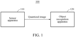
- FIG. 1 illustrates an example of an object recognition system 100.
- the object recognition system 100 includes a sensor apparatus 110 and an object recognition apparatus 120.
- the object recognition system 100 is a system configured to acquire an image using the sensor apparatus 110 and to recognize an object appearing in the image using the object recognition apparatus 120.
- the object recognition system 100 may be used for a face recognition or an object recognition, as non-limiting examples.
- the sensor apparatus 110 acquires an image using an image sensor (for example, a camera) and generate a quantized image by quantizing the acquired image.
- the quantized image is an image with a number of bits less than a number of bits of the image acquired using the image sensor, and may include, for example, a binary image including pixels that each have one of a first pixel value (for example, "0") and a second pixel value (for example, "1").
- the sensor apparatus 110 automatically quantizes an image using a processing unit (for example, an image processor or a microcontroller unit (MCU)) included in the sensor apparatus 110.
- the image processor generates a quantized image by quantizing an image using a trained quantization filter.
- the quantized image is transferred to the object recognition apparatus 120.
- the object recognition apparatus 120 may perform a processing of the quantized image acquired from the sensor apparatus 110, instead of performing a process of quantizing an image.
- the image processor may be a processor configured to perform a function of processing an image in the sensor apparatus 110, and should not be interpreted as being limited to a processor configured to perform only a function of processing an image.
- the image processor may perform functions (for example, controlling of the sensor apparatus 110) other than an image processing of the quantization processing.
- the object recognition system 100 improves the technical fields of image quantization, image recognition, and the functioning of computers by minimizing an amount of important information to be lost in an image quantization process using an optimal quantization filter trained through a training process, thus reducing an object recognition performance degradation due to use of a quantized image.
- the object recognition apparatus 120 receives the quantized image generated by the sensor apparatus 110 from the sensor apparatus 110 and perform an object recognition based on the quantized image.
- the object recognition apparatus 120 performs the object recognition on the quantized image using a trained object recognition model.
- the object recognition model may be, for example, a neural network model, and may provide a score (for example, an expected value or a probability value) indicating a type of an object appearing in the quantized image based on image information (for example, pixel value information) of the quantized image input to the object recognition model.
- the neural network model used as the object recognition model may include, for example, a deep neural network (DNN) (for example, a convolutional neural network (CNN) or a recurrent neural network (RNN)), however, the type of object recognition models is not limited thereto.
- DNN deep neural network
- CNN convolutional neural network
- RNN recurrent neural network
- Neural network models for example, autoencoders or generative adversarial networks (GANs) may also be used as object recognition models, and the type and forms of neural network models are not limited.
- the object recognition model may be a neural network model having a bit width corresponding to a bit width of the quantized image.
- the object recognition model improves the technical fields of image quantization, image recognition, and the functioning of computers by reducing an amount of resources and increasing a processing speed used to perform object recognition.
- the object recognition model improves the technical fields of image quantization, image recognition, and the functioning of computers by using a low bit width so that the object recognition system 100 may perform an object recognition process with a low power, a low memory usage and at a high speed, in a limited embedded system (for example, a smart sensor or a smartphone).
- FIG. 2 illustrates an example of an object recognition process.
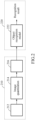
- the object recognition process may include operation 210 of generating a quantized image in a sensor apparatus (for example, the sensor apparatus 110 of FIG. 1 ), and operation 220 of performing an object recognition based on the quantized image in an object recognition apparatus (for example, the object recognition apparatus 120 of FIG. 1 ).
- the sensor apparatus may acquire an image 212 using an image sensor and generate a quantized image 216 through an image quantization process 214.
- the image 212 acquired using the image sensor may have a pixel value represented by a number of bits (for example, 8 bits, 10 bits or 12 bits) and the quantized image 216 may have a pixel value represented by a smaller number of bits (for example, 2 bits or 4 bits).
- the sensor apparatus may quantize the image 212 using a halftone scheme.
- the halftone scheme may be a scheme of converting an image with a high bit width into an image (for example, a binary image) with a low bit width, and may also be a scheme of representing a pixel value of an image as a density in a two-dimensional (2D) space.
- the sensor apparatus may quantize the image 212 using a trained quantization filter, or using an error diffusion scheme. A non-limiting example of using the error diffusion scheme will be further described below with reference to FIG. 8 . In the following description, an example of quantizing the image 212 using the quantization filter is described.
- the quantization filter used in the image quantization process 214 may be a dither matrix generated through the training process.
- the dither matrix may have different threshold values for each position as elements.
- the dither matrix may include a plurality of channels.
- the quantized image 216 optimized as an input of an object recognition model 222 used for an object recognition may be generated.
- Non-limiting examples of a training process of the dither matrix will be further described below with reference to FIGS. 5A and 5B .
- the quantized image 216 may be transferred to the object recognition apparatus via an output interface of the sensor apparatus.
- the image 212 acquired using the image sensor may be converted into the quantized image 216 having a number of bits less than that of the image 212 in the sensor apparatus and the quantized image 216 may be transmitted to the object recognition apparatus, and thus a quantity of data transmitted may be reduced in comparison to when acquired image is transmitted directly to an object recognition apparatus.
- the object recognition apparatus may perform the object recognition using the object recognition model 222.
- the object recognition model 222 may be, for example, a trained neural network model and may provide a recognition result of the object recognition based on the input quantized image 216.
- the object recognition process may be performed under a control of a processor (for example, a central processing unit (CPU), a graphics processing unit (GPU), or a neural network processing unit (NPU)) included in the object recognition apparatus.
- a processor for example, a central processing unit (CPU), a graphics processing unit (GPU), or a neural network processing unit (NPU) included in the object recognition apparatus.
- the object recognition model 222 may output a score indicating a possibility or a probability that an object appearing in the quantized image 216 corresponds to each class or label.
- the object recognition apparatus may determine an object recognition result based on information associated with the score.
- the quantized image 216 may be input to the object recognition model 222 having a low bit width.
- the low bit width represents, for example, a small number of bits (for example, 4 bits).
- a neural network model with a low bit width may be used as the object recognition model 222 for a high-speed operation in a limited resource environment (for example, a low-power and low-capacity memory).
- the quantized image 216 that is an image with a small number of bits may be used as an input to the object recognition model 222.
- the sensor apparatus may reduce a degree to which important information is lost in the image quantization process 214 using a trained quantization filter, and thus the sensor apparatus increases an accuracy and a confidence of the object recognition result.
- FIG. 3 illustrates an example of a quantized image generation method.
- the quantized image generation method of FIG. 3 may be performed by, for example, a sensor apparatus (for example, the sensor apparatus 110 of FIG. 1 ).
- the sensor apparatus may acquire an image using an image sensor (for example, a camera).
- the acquired image may have a large number of bits, and the sensor apparatus may automatically perform an image processing to reduce the number of bits of the image using a processing unit such as an image processor or an MCU included in the sensor apparatus.
- a processing unit such as an image processor or an MCU included in the sensor apparatus.
- the sensor apparatus may generate a quantized image by quantizing the image acquired in operation 310 using a quantization filter that is trained.
- the quantized image may have a number of bits less than that of the image acquired using the image sensor, and may be, for example, a binary image.
- the quantization filter may be, for example, a dither matrix, and the sensor apparatus may apply the dither matrix to the image acquired using the image sensor to generate the quantized image.
- the dither matrix may include a single channel or a plurality of channels, and a plurality of threshold values included as elements of the dither matrix may be determined through the training process. Through the training process, the elements of the dither matrix may be determined to minimize an object recognition performance degradation that may occur due to use of the quantized image.
- the sensor apparatus may perform a convolution operation prior to the quantization process.
- the sensor apparatus may perform a convolution operation on the image acquired using the image sensor, using a trained convolution filter.
- the sensor apparatus may generate a quantized image by quantizing the image on which the convolution operation is performed, using a trained quantization filter.
- a non-limiting example of a training process of the convolution filter and the quantization filter will be further described below with reference to FIG. 7 .
- the sensor apparatus may transmit the quantized image generated in operation 320 externally from the sensor apparatus via an output interface.
- the image acquired using the image sensor may be quantized in the sensor apparatus and the quantized image may be output from the sensor apparatus.
- the quantized image may be transmitted via a wire or wirelessly using the output interface.
- the sensor apparatus may transfer the quantized image to the object recognition apparatus, and the object recognition apparatus may recognize an object appearing in the quantized image using an object recognition model having a bit width corresponding to a bit width of the quantized image.
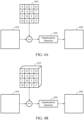
- FIGS. 4A and 4B illustrate examples of a process of generating a quantized image using a quantization filter.
- a sensor apparatus may generate a quantized image 440 by quantizing an image 410 using a trained dither matrix 420 as a quantization filter.
- the dither matrix 420 may have different threshold values as elements and a size of the dither matrix 420 is not limited and may be variously set.
- a dither matrix 425 may include a plurality of channels.
- the dither matrix 425 may include dither matrices for three channels, and may have different threshold values for each channel as elements.
- the sensor apparatus may apply the dither matrix 420 to pixel values of pixels included in the image 410 and apply a quantization function 430 to a result obtained by applying the dither matrix 420 to the pixel values, to generate the quantized image 440.
- the sensor apparatus may subtract a threshold value included in the dither matrix 420 from pixel values of pixels to which the dither matrix 420 is to be applied among all pixels in the image 410.
- a value of "7" may be assigned to the pixel A as a result obtained by applying the dither matrix 420.
- the sensor apparatus may apply the quantization function 430 to the value of "7" of the pixel A to replace the pixel value of the pixel A with a quantized value.
- the pixel value of the pixel A may be replaced with a quantized value of "1" in response to the value of "7" of the pixel A being a positive value.
- a value of "-2" is assigned to a pixel B as a result of the applying of the dither matrix 420, a pixel value of the pixel B may be replaced with a quantized value of "0" as a result of applying of the quantization function 430 when the value of "-2" of the pixel B is a negative value.
- a pixel of the quantized image 440 may have be generated to have a value of "1" when a corresponding pixel generated by applying the dither matrix 420 to a pixel of the image 410 has a positive value, and a pixel of the quantized image 440 may have be generated to have a value of "0" when a corresponding pixel generated by applying the dither matrix 420 to a pixel of the image 410 has a negative value.
- the sensor apparatus may perform the above process of each of the pixels in the image 410, to generate the quantized image 440 having pixels that each have quantized pixel values.
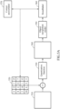
- FIGS. 5A and 5B illustrate examples of a training process of a quantization filter.
- Elements of a quantization filter used to generate a quantized image by a sensor apparatus may be determined through the training process.
- a dither matrix may be used as a quantization filter.
- a training image 510 may be selected as training data, and a trainable quantization filter 520 may be applied to the training image 510.
- the training image 510 may be, for example, an image with a relatively large number of bits, for example, 8 bits.
- a quantization function 530 may be applied to a result obtained by subtracting a threshold value included in the quantization filter 520 from a pixel value of each of pixels to which the quantization filter 520 is to be applied among all pixels in the training image 510.
- a sign function may be used as the quantization function 530.
- the quantization function 530 may assign a quantized value to a pixel value of a corresponding pixel based on the result obtained by subtracting the threshold value, and a training image 540 quantized based on a result of applying the quantization function 530 may be generated.
- the quantized training image 540 (for example, a 1-bit binary image) may be generated by quantizing the training image 510 using the quantization filter 520.
- the quantized training image 540 may be input to an object recognition model 550.
- a result label 560 output from the object recognition model 550 is obtained.
- the object recognition model 550 may be based on a neural network model, and may provide score information about a type of an object appearing in the quantized training image 540 based on a calculation result of the neural network model.
- a loss is calculated based on a difference between the result label 560 and a correct answer label 570 of a real or predetermined object appearing in the training image 510, and elements (for example, threshold values of a dither matrix) of the quantization filter 520 are adjusted to reduce the loss based on a backpropagation algorithm.
- the correct answer label 570 may correspond to a desired value corresponding to the training image 510.
- the quantization filter 520 may be trained to minimize an object recognition performance degradation due to use of a quantized image of the object recognition model 550.
- the object recognition model 550 may be trained as well as the quantization filter 520 in the training process, and accordingly parameters of the object recognition model 550 may also be adjusted.
- the above training process may be repeatedly performed for each of various training images, and elements of the quantization filter 520 may be iteratively updated to desired values through a large number of training processes. For example, elements of the quantization filter 520 may be iteratively updated using the training process until the calculated loss is less than or equal to a predetermined threshold.
- the training process of the quantization filter 520 is performed.
- the training process of the quantization filter 520 when the training image 510 is input to the object recognition model 550, a first result label 560 output from the object recognition model 550 is obtained.
- the quantized training image 540 generated by quantizing the training image 510 using the quantization filter 520 and the quantization function 530 is input to the object recognition model 550, a second result label 560 output from the object recognition model 550 is obtained.
- a loss is calculated based on a difference between the first result label 560 and the second result label 560, and elements of the quantization filter 520 are adjusted to reduce the loss based on the backpropagation algorithm to train the quantization filter 520 .
- the first result label 560 and the second result label 560 may be in forms of, for example, embedding vectors.
- the trained quantization filter 520 may correspond to the dither matrix 420 of FIG. 4A , in an example.
- FIG. 5B illustrates an example in which a quantization filter 525 is a dither matrix including a plurality of channels.
- the training process described above with reference to FIG. 5A is equally applicable to a process of training the quantization filter 525, except that threshold values of a dither matrix for each channel is adjusted in the quantization filter 525 forming a plurality of channels, instead of or in addition to the quantization filter 520 for a single channel, to train the quantization filter 525.
- the trained quantization filter 525 corresponds to the dither matrix 425 of FIG. 4B , in an example.
- FIG. 6 illustrates an example of an object recognition process.
- the object recognition process includes operation 610 of generating a quantized image in a sensor apparatus (for example, the sensor apparatus 110 of FIG. 1 ), and operation 620 of performing an object recognition based on the quantized image in an object recognition apparatus (for example, the object recognition apparatus 120 of FIG. 1 ).
- the sensor apparatus may acquire an image 612 using an image sensor and perform a convolution operation by applying a convolution filter to the acquired image 612 in operation 614.
- the convolution filter may be a trained convolution filter, and the trained convolution filter may be determined through a training process.
- the sensor apparatus may perform an image quantization 616 on an image 612 to which the convolution filter is applied, and generate a quantized image 618.
- the sensor apparatus may perform the image quantization 616 using a trained quantization filter. By performing a convolution operation on the image 612 before performing the image quantization 616, the image 612 may be adjusted to more accurately represent an image feature associated with an object.
- the quantized image 618 may be transferred to the object recognition apparatus.
- the object recognition apparatus may perform the object recognition based on the quantized image 618.
- the object recognition apparatus may input the quantized image 618 to the object recognition model 622, and the object recognition model 622 may provide a recognition result of the object recognition based on the quantized image 618.
- the object recognition model 622 may provide information associated with a result label corresponding to the quantized image 618.
- FIG. 7 illustrates an example of a training process of a convolution filter and a quantization filter.
- a training image 710 may be provided as training data.
- the training image 710 is, for example, an image with a relatively large number of bits (for example, 8 bits).
- a convolution operation 725 may be performed on the training image 710 based on a trainable convolution filter 720, and an image quantization 735 may be performed on the training image on which the convolution operation 725 is performed, based on a trainable quantization filter 730.
- a quantized training image 740 may be generated as a result obtained by performing the image quantization 735, and the generated quantized training image 740 may be input to an object recognition model 750.
- the object recognition model 750 may output a result label 760 corresponding to the quantized training image 740, and a loss may be determined based on a difference between the result label 760 and a correct answer label 770 corresponding to the original training image 710. Elements or parameters of the convolution filter 720 and the quantization filter 730 may be adjusted to minimize the loss based on, for example, a backpropagation algorithm to train the convolution filter 720 and the quantization filter 730.
- the above training process may be repeatedly performed for each of training images, and the convolution filter 720 and the quantization filter 730 may be iteratively desirably changed through a large number of training processes.
- the elements or the parameters of the convolution filter 720 and the quantization filter 730 may be iteratively updated using the training process until the determined loss is less than or equal to a predetermined threshold.
- the trained quantization filter 730 may correspond to either of the dither matrix 420 of FIG. 4A and the dither matrix 425 of FIG. 4B , in an example.
- FIG. 8 illustrates an example of a quantized image generation method (for example, using an error diffusion scheme).
- the error diffusion scheme may be a scheme of propagating a quantization error caused by a quantization to neighboring pixels and compensating for the quantization error.
- a sensor apparatus for example, the sensor apparatus 110 of FIG. 1
- the sensor apparatus may acquire an image using an image sensor.
- the sensor apparatus may select a current pixel from the acquired image. For example, the current pixel may be selected in a raster scan order.
- a pixel value of the selected current pixel is greater than a threshold value.
- the threshold value may be an intermediate value of the range, that is, "127.5".
- the sensor apparatus may determine the threshold value to be an average of the minimum and maximum pixel value (for example, "127.5").
- the threshold value is not limited thereto.
- a first reference value may be selected as a reference value used to calculate a quantization error in operation 840.
- a second reference value is selected as a reference value used to calculate a quantization error in operation 845.
- the first reference value may correspond to "63.75” that is an intermediate value of a first quantization interval of "0" to "127.5"
- the second reference value may correspond to "191.25" that is an intermediate value of a second quantization interval of "127.5" to "255".
- the sensor apparatus may determine the first reference value to be an average of the minimum pixel value and the threshold value (for example, "63.75") and may determine the second reference value to be an average of the threshold value and the maximum pixel value (for example, "191.25").
- the sensor apparatus may calculate an error corresponding to the current pixel based on the pixel value of the current pixel and a quantization interval including the pixel value of the current pixel.
- the first reference value of "63.75” may be selected in operation 840 in response to the pixel value of the current pixel being less than "127.5" that is the threshold value.
- "36.25” obtained by subtracting the first reference value of "63.75” from the pixel value of "100” may be calculated as an error.
- the second reference value of "191.25" may be selected in operation 845 in response to the pixel value of the current pixel is greater than "127.5" that is the threshold value.
- "-51.25" obtained by subtracting the second reference value of "191.25" from the pixel value of "140” may be calculated as an error.
- the sensor apparatus may adjust a pixel value of a neighboring pixel of the current pixel based on the error corresponding to the current pixel calculated in operation 850. For example, the sensor apparatus may add a value obtained by applying a predetermined weight to the error to the pixel value of the neighboring pixel.
- the neighboring pixel may correspond to at least one pixel on which a quantization processing is not yet performed among pixels adjacent to the current pixel, and different weights may be applied to neighboring bipolar pixels.
- the sensor apparatus may apply the error to a neighboring pixel based on a Floyd-Steinberg algorithm.
- the neighboring pixel may include a pixel located to each of the right, bottom-left, bottom, and bottom-right of the current pixel.
- the error corresponding to the current pixel may be propagated to neighboring pixels, pixel values of the neighboring pixels may be adjusted, and an image quantization may be performed based on the adjusted pixel values.
- the sensor apparatus may generate a quantized image by matching the pixel value of the current pixel to a quantized pixel value.
- a quantization interval for example, an interval from the minimum pixel value to the threshold value
- the sensor apparatus may match the pixel value of the current pixel to a first quantized pixel value, for example, "0".
- the pixel value of the current pixel is included in a second quantization interval (for example, an interval from the threshold value to the maximum pixel value)
- the sensor apparatus may match the pixel value of the current pixel to a second quantized pixel value, for example, "1".
- a quantization of an image may be performed by a binary quantization, a bipolar quantization, or a ternary quantization, however, examples are not limited thereto.
- a pixel value of an image may be mapped to any one or any combination of "-1", "0", and "1" and the image may be quantized.
- three quantization intervals may exist. A reference value of each of the three quantization intervals may be set as an intermediate value of each of the three quantization intervals.
- an intermediate value of a quantization interval may be set as a reference value, to minimize a quantization error.
- the quantization error may have a range of "-127” to "127”.
- the quantization error may have a range of "-63.75" to "63.75".
- the range of the quantization error may be minimized to reduce an error between the quantized image and the original image.
- An intermediate value of a quantization interval may be used as a reference value of the quantization interval as described above, or all values other than a minimum value, for example, "0" and a maximum value, for example, "255", may be used as a reference value of the quantization interval.
- the reference value of the quantization interval may also be determined through a training process.
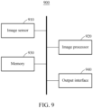
- FIG. 9 illustrates an example of a sensor apparatus (for example, a sensor apparatus 900).
- the sensor apparatus 900 may include an image sensor 910, an image processor 920 (for example, one or more processors), a memory 930, and an output interface 940.
- the sensor apparatus 900 may correspond to a sensor apparatus described in the present disclosure (for example, the sensor apparatus 110 of FIG. 1 ).
- the image sensor 910 may acquire an image.
- the image sensor 910 may acquire an image (for example, a color image, a grayscale image, or an infrared image).
- the image processor 920 may control an operation of the sensor apparatus 900, and may include, for example, any one or any combination of a digital signal processor (DSP), an image signal processor (ISP), and an MCU.
- the image processor 920 may generate a quantized image by performing an image quantization processing on the image acquired by the image sensor 910.
- the image processor 920 may perform one or more or all operations associated with the image quantization described above with reference to FIGS. 1 through 8 .
- the image processor 920 may generate a quantized image (for example, a binary image) by quantizing an image acquired using a trained quantization filter (for example, a dither matrix).
- a quantized image for example, a binary image
- the image processor 920 may generate a quantized image by performing a convolution operation on the image acquired by the image sensor 910 using a trained convolution filter and by quantizing the image on which the convolution operation is performed using a trained quantization filter.
- the image processor 920 may generate a quantized image using the error diffusion scheme described above with reference to FIG. 8 .
- the image processor 920 may calculate an error corresponding to a current pixel included in the image, based on a pixel value of the current pixel and a quantization interval including the pixel value, may adjust a pixel value of a neighboring pixel of the current pixel based on the calculated error, and may generate the quantized image based on an adjustment result.
- the memory 930 may store instructions to be executed by the processor 920, and information used to perform an image quantization.
- the memory 930 may store information associated with the image acquired by the image sensor 910 and a quantized image generated through an image quantization processing.
- the memory 930 may include, for example, a high-speed random access memory (RAM) and/or a non-volatile computer-readable storage medium.
- the output interface 940 may transmit the quantized image generated by the image processor 920 externally from the sensor apparatus 900.
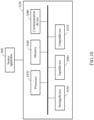
- the output interface 940 may transmit the quantized image to an object recognition apparatus (for example, the object recognition apparatus 120 of FIG. 1 or the object recognition apparatus 1020 of FIG. 10 discussed below) via a wired or wireless communication.
- FIG. 10 illustrates an example of an apparatus or system including a sensor apparatus (for example, the sensor apparatus 900) and an object recognition apparatus (for example, an object recognition apparatus 1020).
- a sensor apparatus for example, the sensor apparatus 900
- an object recognition apparatus for example, an object recognition apparatus 1020
- the object recognition apparatus 1020 may include a processor 1030 (for example, one or more processors), a memory 1040, a storage device 1050, an input device 1060, an output device 1070, and a communication device 1080. Components of the object recognition apparatus 1020 may communicate with each other via a communication bus.
- the object recognition apparatus 1020 may correspond to the object recognition apparatus described in the present disclosure (for example, the object recognition apparatus 120 of FIG. 1 ).
- the processor 1030 may control an operation of the object recognition apparatus 1020 and execute functions and instructions to perform an object recognition.
- the processor 1030 may execute instructions stored in the memory 1040 or the storage device 1050.
- the processor 1030 may include, for example, any one or any combination of a CPU, a GPU, and an NPU, and may perform one or more or all operations associated with the object recognition described above with reference to FIGS. 1 through 9 .
- the processor 1030 may perform the object recognition based on the quantized image received from the sensor apparatus 900.
- the memory 1040 may store instructions to be executed by the processor 1030 and information used to perform the object recognition.
- the memory 1040 may include, for example, a high-speed RAM and/or a non-volatile computer-readable storage medium.
- the storage device 1050 may include a non-transitory computer-readable storage medium.
- the storage device 1050 may store a larger amount of information than that of the memory 1040 for a relatively long period of time.
- the storage device 1050 may include a hard disk, an optical disk, or a solid state drive (SSD).
- Information about an object recognition model used for an object recognition may be stored in the memory 1040 and/or the storage device 1050.
- the input device 1060 may receive an input from a user through a tactile input, a video input, an audio input, and/or a touch input.
- the input device 1060 may detect an input from a keyboard, a mouse, a touchscreen, a microphone, and/or the user, and may include any other device configured to transfer the detected input to the object recognition apparatus 1020.
- the output device 1070 may provide a user with an output of the object recognition apparatus 1020 through a visual channel, an auditory channel, and/or a tactile channel.
- the output device 1070 may include, for example, a display, a touchscreen, a speaker, a vibration generator, or other devices configured to provide the user with the output.
- the communication device 1080 may communicate with an external device via a wired or wireless network.
- the communication device 1080 may receive the quantized image from the sensor apparatus 900 via a mobile industry processor interface (MIPI).
- MIPI mobile industry processor interface
- the object recognition systems, sensor apparatuses, object recognition apparatuses, image sensors, image processors, memories, output interfaces, processors, storage devices, input devices, output devices, communication devices, object recognition system 100, sensor apparatus 110, object recognition apparatus 120, sensor apparatus 900, image sensor 910, image processor 920, memory 930, output interface 940, object recognition apparatus 1020, processor 1030, memory 1040, storage device 1050, input device 1060, output device 1070, communication device 1080, apparatuses, units, modules, devices, and other components described herein with respect to FIGS. 1-10 are implemented by or representative of hardware components.
- Examples of hardware components that may be used to perform the operations described in this application where appropriate include controllers, sensors, generators, drivers, memories, comparators, arithmetic logic units, adders, subtractors, multipliers, dividers, integrators, and any other electronic components configured to perform the operations described in this application.
- one or more of the hardware components that perform the operations described in this application are implemented by computing hardware, for example, by one or more processors or computers.
- a processor or computer may be implemented by one or more processing elements, such as an array of logic gates, a controller and an arithmetic logic unit, a digital signal processor, a microcomputer, a programmable logic controller, a field-programmable gate array, a programmable logic array, a microprocessor, or any other device or combination of devices that is configured to respond to and execute instructions in a defined manner to achieve a desired result.
- a processor or computer includes, or is connected to, one or more memories storing instructions or software that are executed by the processor or computer.
- Hardware components implemented by a processor or computer may execute instructions or software, such as an operating system (OS) and one or more software applications that run on the OS, to perform the operations described in this application.
- OS operating system
- the hardware components may also access, manipulate, process, create, and store data in response to execution of the instructions or software.
- processor or “computer” may be used in the description of the examples described in this application, but in other examples multiple processors or computers may be used, or a processor or computer may include multiple processing elements, or multiple types of processing elements, or both.
- a single hardware component or two or more hardware components may be implemented by a single processor, or two or more processors, or a processor and a controller.
- One or more hardware components may be implemented by one or more processors, or a processor and a controller, and one or more other hardware components may be implemented by one or more other processors, or another processor and another controller.
- One or more processors may implement a single hardware component, or two or more hardware components.
- a hardware component may have any one or more of different processing configurations, examples of which include a single processor, independent processors, parallel processors, single-instruction single-data (SISD) multiprocessing, single-instruction multiple-data (SIMD) multiprocessing, multiple-instruction single-data (MISD) multiprocessing, and multiple-instruction multiple-data (MIMD) multiprocessing.
- SISD single-instruction single-data
- SIMD single-instruction multiple-data
- MIMD multiple-instruction multiple-data
- FIGS. 1-10 that perform the operations described in this application are performed by computing hardware, for example, by one or more processors or computers, implemented as described above executing instructions or software to perform the operations described in this application that are performed by the methods.
- a single operation or two or more operations may be performed by a single processor, or two or more processors, or a processor and a controller.
- One or more operations may be performed by one or more processors, or a processor and a controller, and one or more other operations may be performed by one or more other processors, or another processor and another controller.
- One or more processors, or a processor and a controller may perform a single operation, or two or more operations.
- Instructions or software to control computing hardware may be written as computer programs, code segments, instructions or any combination thereof, for individually or collectively instructing or configuring the one or more processors or computers to operate as a machine or special-purpose computer to perform the operations that are performed by the hardware components and the methods as described above.
- the instructions or software include machine code that is directly executed by the one or more processors or computers, such as machine code produced by a compiler.
- the instructions or software includes higher-level code that is executed by the one or more processors or computer using an interpreter.
- the instructions or software may be written using any programming language based on the block diagrams and the flow charts illustrated in the drawings and the corresponding descriptions used herein, which disclose algorithms for performing the operations that are performed by the hardware components and the methods as described above.
- the instructions or software to control computing hardware for example, one or more processors or computers, to implement the hardware components and perform the methods as described above, and any associated data, data files, and data structures, may be recorded, stored, or fixed in or on one or more non-transitory computer-readable storage media.
- Examples of a non-transitory computer-readable storage medium include read-only memory (ROM), random-access programmable read only memory (PROM), electrically erasable programmable read-only memory (EEPROM), random-access memory (RAM), dynamic random access memory (DRAM), static random access memory (SRAM), flash memory, non-volatile memory, CD-ROMs, CD-Rs, CD+Rs, CD-RWs, CD+RWs, DVD-ROMs, DVD-Rs, DVD+Rs, DVD-RWs, DVD+RWs, DVD-RAMs, BD-ROMs, BD-Rs, BD-R LTHs, BD-REs, blue-ray or optical disk storage, hard disk drive (HDD), solid state drive (SSD), flash memory, a card type memory such as multimedia card micro or a card (for example, secure digital (SD) or extreme digital (XD)), magnetic tapes, floppy disks, magneto-optical data storage devices, optical data storage devices, hard disks,
- the instructions or software and any associated data, data files, and data structures are distributed over network-coupled computer systems so that the instructions and software and any associated data, data files, and data structures are stored, accessed, and executed in a distributed fashion by the one or more processors or computers.
Landscapes
- Engineering & Computer Science (AREA)
- Theoretical Computer Science (AREA)
- Physics & Mathematics (AREA)
- General Physics & Mathematics (AREA)
- Data Mining & Analysis (AREA)
- Multimedia (AREA)
- Artificial Intelligence (AREA)
- Evolutionary Computation (AREA)
- Life Sciences & Earth Sciences (AREA)
- General Engineering & Computer Science (AREA)
- Signal Processing (AREA)
- Health & Medical Sciences (AREA)
- Mathematical Physics (AREA)
- Biophysics (AREA)
- General Health & Medical Sciences (AREA)
- Molecular Biology (AREA)
- Computing Systems (AREA)
- Biomedical Technology (AREA)
- Computational Linguistics (AREA)
- Software Systems (AREA)
- Bioinformatics & Cheminformatics (AREA)
- Bioinformatics & Computational Biology (AREA)
- Computer Vision & Pattern Recognition (AREA)
- Evolutionary Biology (AREA)
- Discrete Mathematics (AREA)
- Image Analysis (AREA)
Description
- The following description relates to a method and apparatus with quantized image generation.
- A neural network may have an operation structure in which a large number of processing devices having simple functions are connected in parallel. To solve an issue of classifying an input pattern into a predetermined group, the neural network may be implemented with an algorithm with a learning ability. The neural network may have a generalization ability to generate a relatively correct output for an input pattern that has not been used for training, based on a result of the training.
- However, the neural network may have a limitation of requiring a large amount of resources to process data.
- Reference is made to the following prior art documents: CAO YUE ET AL: "Deep Visual-Semantic Quantization for Efficient Image Retrieval",2017 IEEE CONFERENCE ON COMPUTER VISION AND PATTERN RECOGNITION (CVPR), IEEE COMPUTER SOCIETY, US, 21 July 2017 (2017-07-21), pages 916-925, XP033249430,ISSN: 1063-6919, DOI: 10.1109/CVPR.2017.104 and
CN 110 019 907 A (BEIJING SOGOU TECH DEV CO) 16 July 2019 - The invention is set out in the appended set of claims.
-
-
FIG. 1 illustrates an object recognition system. -
FIG. 2 illustrates an object recognition process. -
FIG. 3 illustrates a quantized image generation method -
FIGS. 4A and 4B illustrate a process of generating a quantized image using a quantization filter. -
FIGS. 5A and5B illustrate a training process of a quantization filter. -
FIG. 6 illustrates an object recognition process. -
FIG. 7 illustrates a training process of a convolution filter and a quantization filter. -
FIG. 8 illustrates a quantized image generation method -
FIG. 9 illustrates a sensor apparatus. -
FIG. 10 illustrates an apparatus comprising a sensor apparatus and an object recognition apparatus. - Throughout the drawings and the detailed description, unless otherwise described or provided, the same drawing reference numerals will be understood to refer to the same elements, features, and structures. The drawings may not be to scale, and the relative size, proportions, and depiction of elements in the drawings may be exaggerated for clarity, illustration, and convenience.
- The following detailed description is provided to assist the reader in gaining a comprehensive understanding of the methods, apparatuses, and/or systems described herein.
- Although terms of "first" or "second" are used herein to describe various members, components, regions, layers, or sections, these members, components, regions, layers, or sections are not to be limited by these terms. Rather, these terms are only used to distinguish one member, component, region, layer, or section from another member, component, region, layer, or section. Thus, a first member, component, region, layer, or section referred to in examples described herein may also be referred to as a second member, component, region, layer, or section without departing from the teachings of the examples.
- Unless otherwise defined, all terms, including technical and scientific terms, used herein have the same meaning as commonly understood by one of ordinary skill in the art to which this disclosure pertains consistent with and after an understanding of the present disclosure. Terms, such as those defined in commonly used dictionaries, are to be interpreted as having a meaning that is consistent with their meaning in the context of the relevant art and the present disclosure, and are not to be interpreted in an idealized or overly formal sense unless expressly so defined herein. The use of the term "may" herein with respect to an example or embodiment (for example, as to what an example or embodiment may include or implement) means that at least one example or embodiment exists where such a feature is included or implemented, while all examples are not limited thereto.
- Hereinafter, examples will be described in detail with reference to the accompanying drawings, and like reference numerals in the drawings refer to like elements throughout.
-
FIG. 1 illustrates an example of anobject recognition system 100. - Referring to
FIG. 1 , theobject recognition system 100 includes asensor apparatus 110 and anobject recognition apparatus 120. Theobject recognition system 100 is a system configured to acquire an image using thesensor apparatus 110 and to recognize an object appearing in the image using theobject recognition apparatus 120. For example, theobject recognition system 100 may be used for a face recognition or an object recognition, as non-limiting examples. - The
sensor apparatus 110 acquires an image using an image sensor (for example, a camera) and generate a quantized image by quantizing the acquired image. The quantized image is an image with a number of bits less than a number of bits of the image acquired using the image sensor, and may include, for example, a binary image including pixels that each have one of a first pixel value (for example, "0") and a second pixel value (for example, "1"). - The
sensor apparatus 110 automatically quantizes an image using a processing unit (for example, an image processor or a microcontroller unit (MCU)) included in thesensor apparatus 110. The image processor generates a quantized image by quantizing an image using a trained quantization filter. The quantized image is transferred to theobject recognition apparatus 120. As described above, theobject recognition apparatus 120 may perform a processing of the quantized image acquired from thesensor apparatus 110, instead of performing a process of quantizing an image. A quantization processing is performed in thesensor apparatus 110 and the quantized image is transmitted from thesensor apparatus 110 to theobject recognition apparatus 120, and thus theobject recognition system 100 improves the technical fields of image quantization, image recognition, and the functioning of computers by reducing both an amount of data and a bandwidth used for transmitting the image information from thesensor apparatus 110 to theobject recognition apparatus 120, in comparison to when an acquired image that is not quantized is transmitted directly from a sensor apparatus to an object recognition apparatus. In the present disclosure, the image processor may be a processor configured to perform a function of processing an image in thesensor apparatus 110, and should not be interpreted as being limited to a processor configured to perform only a function of processing an image. Depending on examples, the image processor may perform functions (for example, controlling of the sensor apparatus 110) other than an image processing of the quantization processing. - In a typical process of quantizing an image, a large amount of information may be lost. Such information loss may have an influence on a result of an object recognition. The
object recognition system 100 improves the technical fields of image quantization, image recognition, and the functioning of computers by minimizing an amount of important information to be lost in an image quantization process using an optimal quantization filter trained through a training process, thus reducing an object recognition performance degradation due to use of a quantized image. - The
object recognition apparatus 120 receives the quantized image generated by thesensor apparatus 110 from thesensor apparatus 110 and perform an object recognition based on the quantized image. Theobject recognition apparatus 120 performs the object recognition on the quantized image using a trained object recognition model. The object recognition model may be, for example, a neural network model, and may provide a score (for example, an expected value or a probability value) indicating a type of an object appearing in the quantized image based on image information (for example, pixel value information) of the quantized image input to the object recognition model. - The neural network model used as the object recognition model may include, for example, a deep neural network (DNN) (for example, a convolutional neural network (CNN) or a recurrent neural network (RNN)), however, the type of object recognition models is not limited thereto. Neural network models (for example, autoencoders or generative adversarial networks (GANs)) may also be used as object recognition models, and the type and forms of neural network models are not limited.
- For example, the object recognition model may be a neural network model having a bit width corresponding to a bit width of the quantized image. By using a neural network model having a low bit width corresponding to the bit width of the quantized image, the object recognition model improves the technical fields of image quantization, image recognition, and the functioning of computers by reducing an amount of resources and increasing a processing speed used to perform object recognition. In an example, the object recognition model improves the technical fields of image quantization, image recognition, and the functioning of computers by using a low bit width so that the
object recognition system 100 may perform an object recognition process with a low power, a low memory usage and at a high speed, in a limited embedded system (for example, a smart sensor or a smartphone). -
FIG. 2 illustrates an example of an object recognition process. - Referring to
FIG. 2 , the object recognition process may includeoperation 210 of generating a quantized image in a sensor apparatus (for example, thesensor apparatus 110 ofFIG. 1 ), andoperation 220 of performing an object recognition based on the quantized image in an object recognition apparatus (for example, theobject recognition apparatus 120 ofFIG. 1 ). - In
operation 210, the sensor apparatus may acquire animage 212 using an image sensor and generate a quantizedimage 216 through animage quantization process 214. Theimage 212 acquired using the image sensor may have a pixel value represented by a number of bits (for example, 8 bits, 10 bits or 12 bits) and the quantizedimage 216 may have a pixel value represented by a smaller number of bits (for example, 2 bits or 4 bits). - In the
image quantization process 214, the sensor apparatus may quantize theimage 212 using a halftone scheme. The halftone scheme may be a scheme of converting an image with a high bit width into an image (for example, a binary image) with a low bit width, and may also be a scheme of representing a pixel value of an image as a density in a two-dimensional (2D) space. The sensor apparatus may quantize theimage 212 using a trained quantization filter, or using an error diffusion scheme. A non-limiting example of using the error diffusion scheme will be further described below with reference toFIG. 8 . In the following description, an example of quantizing theimage 212 using the quantization filter is described. - The quantization filter used in the
image quantization process 214 may be a dither matrix generated through the training process. The dither matrix may have different threshold values for each position as elements. Depending on examples, the dither matrix may include a plurality of channels. By using the dither matrix generated through the training process, thequantized image 216 optimized as an input of anobject recognition model 222 used for an object recognition may be generated. Non-limiting examples of a training process of the dither matrix will be further described below with reference toFIGS. 5A and5B . - The
quantized image 216 may be transferred to the object recognition apparatus via an output interface of the sensor apparatus. As described above, theimage 212 acquired using the image sensor may be converted into thequantized image 216 having a number of bits less than that of theimage 212 in the sensor apparatus and thequantized image 216 may be transmitted to the object recognition apparatus, and thus a quantity of data transmitted may be reduced in comparison to when acquired image is transmitted directly to an object recognition apparatus. - In
operation 220, the object recognition apparatus may perform the object recognition using theobject recognition model 222. Theobject recognition model 222 may be, for example, a trained neural network model and may provide a recognition result of the object recognition based on the input quantizedimage 216. The object recognition process may be performed under a control of a processor (for example, a central processing unit (CPU), a graphics processing unit (GPU), or a neural network processing unit (NPU)) included in the object recognition apparatus. For example, when thequantized image 216 is input to theobject recognition model 222, theobject recognition model 222 may output a score indicating a possibility or a probability that an object appearing in thequantized image 216 corresponds to each class or label. In this example, the object recognition apparatus may determine an object recognition result based on information associated with the score. - When the
quantized image 216 has a small number of bits, thequantized image 216 may be input to theobject recognition model 222 having a low bit width. The low bit width represents, for example, a small number of bits (for example, 4 bits). A neural network model with a low bit width may be used as theobject recognition model 222 for a high-speed operation in a limited resource environment (for example, a low-power and low-capacity memory). Thequantized image 216 that is an image with a small number of bits may be used as an input to theobject recognition model 222. The sensor apparatus may reduce a degree to which important information is lost in theimage quantization process 214 using a trained quantization filter, and thus the sensor apparatus increases an accuracy and a confidence of the object recognition result. -
FIG. 3 illustrates an example of a quantized image generation method. The quantized image generation method ofFIG. 3 may be performed by, for example, a sensor apparatus (for example, thesensor apparatus 110 ofFIG. 1 ). - Referring to
FIG. 3 , inoperation 310, the sensor apparatus may acquire an image using an image sensor (for example, a camera). The acquired image may have a large number of bits, and the sensor apparatus may automatically perform an image processing to reduce the number of bits of the image using a processing unit such as an image processor or an MCU included in the sensor apparatus. As the above image processing process, inoperation 320, the sensor apparatus may generate a quantized image by quantizing the image acquired inoperation 310 using a quantization filter that is trained. The quantized image may have a number of bits less than that of the image acquired using the image sensor, and may be, for example, a binary image. - The quantization filter may be, for example, a dither matrix, and the sensor apparatus may apply the dither matrix to the image acquired using the image sensor to generate the quantized image. The dither matrix may include a single channel or a plurality of channels, and a plurality of threshold values included as elements of the dither matrix may be determined through the training process. Through the training process, the elements of the dither matrix may be determined to minimize an object recognition performance degradation that may occur due to use of the quantized image.
- For example, the sensor apparatus may perform a convolution operation prior to the quantization process. The sensor apparatus may perform a convolution operation on the image acquired using the image sensor, using a trained convolution filter. The sensor apparatus may generate a quantized image by quantizing the image on which the convolution operation is performed, using a trained quantization filter. A non-limiting example of a training process of the convolution filter and the quantization filter will be further described below with reference to
FIG. 7 . - In
operation 330, the sensor apparatus may transmit the quantized image generated inoperation 320 externally from the sensor apparatus via an output interface. As described above, the image acquired using the image sensor may be quantized in the sensor apparatus and the quantized image may be output from the sensor apparatus. The quantized image may be transmitted via a wire or wirelessly using the output interface. For example, the sensor apparatus may transfer the quantized image to the object recognition apparatus, and the object recognition apparatus may recognize an object appearing in the quantized image using an object recognition model having a bit width corresponding to a bit width of the quantized image. -
FIGS. 4A and 4B illustrate examples of a process of generating a quantized image using a quantization filter. - Referring to
FIG. 4A , a sensor apparatus (for example, thesensor apparatus 110 ofFIG. 1 ) may generate aquantized image 440 by quantizing animage 410 using a traineddither matrix 420 as a quantization filter. Thedither matrix 420 may have different threshold values as elements and a size of thedither matrix 420 is not limited and may be variously set. As shown inFIG. 4B , adither matrix 425 may include a plurality of channels. For example, thedither matrix 425 may include dither matrices for three channels, and may have different threshold values for each channel as elements. - Referring back to
FIG. 4A , the sensor apparatus may apply thedither matrix 420 to pixel values of pixels included in theimage 410 and apply aquantization function 430 to a result obtained by applying thedither matrix 420 to the pixel values, to generate thequantized image 440. For example, the sensor apparatus may subtract a threshold value included in thedither matrix 420 from pixel values of pixels to which thedither matrix 420 is to be applied among all pixels in theimage 410. In an example, when a pixel value of a pixel A in theimage 410 is "12" and a threshold value of thedither matrix 420 to be applied to the pixel A is "5", a value of "7" may be assigned to the pixel A as a result obtained by applying thedither matrix 420. In this example, in generating thequantized image 440, the sensor apparatus may apply thequantization function 430 to the value of "7" of the pixel A to replace the pixel value of the pixel A with a quantized value. For example, when a sign function is used as thequantization function 430, the pixel value of the pixel A may be replaced with a quantized value of "1" in response to the value of "7" of the pixel A being a positive value. In another example, when a value of "-2" is assigned to a pixel B as a result of the applying of thedither matrix 420, a pixel value of the pixel B may be replaced with a quantized value of "0" as a result of applying of thequantization function 430 when the value of "-2" of the pixel B is a negative value. Accordingly, in an example, a pixel of thequantized image 440 may have be generated to have a value of "1" when a corresponding pixel generated by applying thedither matrix 420 to a pixel of theimage 410 has a positive value, and a pixel of thequantized image 440 may have be generated to have a value of "0" when a corresponding pixel generated by applying thedither matrix 420 to a pixel of theimage 410 has a negative value. The sensor apparatus may perform the above process of each of the pixels in theimage 410, to generate thequantized image 440 having pixels that each have quantized pixel values. -
FIGS. 5A and5B illustrate examples of a training process of a quantization filter. - Elements of a quantization filter used to generate a quantized image by a sensor apparatus (for example, the
sensor apparatus 110 ofFIG. 1 ) may be determined through the training process. In the following description, a dither matrix may be used as a quantization filter. - Referring to
FIG. 5A , atraining image 510 may be selected as training data, and atrainable quantization filter 520 may be applied to thetraining image 510. Thetraining image 510 may be, for example, an image with a relatively large number of bits, for example, 8 bits. For example, aquantization function 530 may be applied to a result obtained by subtracting a threshold value included in thequantization filter 520 from a pixel value of each of pixels to which thequantization filter 520 is to be applied among all pixels in thetraining image 510. For example, a sign function may be used as thequantization function 530. Thequantization function 530 may assign a quantized value to a pixel value of a corresponding pixel based on the result obtained by subtracting the threshold value, and atraining image 540 quantized based on a result of applying thequantization function 530 may be generated. As described above, the quantized training image 540 (for example, a 1-bit binary image) may be generated by quantizing thetraining image 510 using thequantization filter 520. - The quantized
training image 540 may be input to anobject recognition model 550. In response to an input of the quantizedtraining image 540 to theobject recognition model 550, aresult label 560 output from theobject recognition model 550 is obtained. Theobject recognition model 550 may be based on a neural network model, and may provide score information about a type of an object appearing in the quantizedtraining image 540 based on a calculation result of the neural network model. A loss is calculated based on a difference between theresult label 560 and acorrect answer label 570 of a real or predetermined object appearing in thetraining image 510, and elements (for example, threshold values of a dither matrix) of thequantization filter 520 are adjusted to reduce the loss based on a backpropagation algorithm. Thecorrect answer label 570 may correspond to a desired value corresponding to thetraining image 510. - As described above, the
quantization filter 520 may be trained to minimize an object recognition performance degradation due to use of a quantized image of theobject recognition model 550. Depending on examples, theobject recognition model 550 may be trained as well as thequantization filter 520 in the training process, and accordingly parameters of theobject recognition model 550 may also be adjusted. - The above training process may be repeatedly performed for each of various training images, and elements of the
quantization filter 520 may be iteratively updated to desired values through a large number of training processes. For example, elements of thequantization filter 520 may be iteratively updated using the training process until the calculated loss is less than or equal to a predetermined threshold. - In another example, when the
object recognition model 550 is trained based on thetraining image 510 and when parameters of theobject recognition model 550 are fixed, the training process of thequantization filter 520 is performed. In the training process of thequantization filter 520, when thetraining image 510 is input to theobject recognition model 550, afirst result label 560 output from theobject recognition model 550 is obtained. When the quantizedtraining image 540 generated by quantizing thetraining image 510 using thequantization filter 520 and thequantization function 530 is input to theobject recognition model 550, asecond result label 560 output from theobject recognition model 550 is obtained. A loss is calculated based on a difference between thefirst result label 560 and thesecond result label 560, and elements of thequantization filter 520 are adjusted to reduce the loss based on the backpropagation algorithm to train thequantization filter 520 . In this example, thefirst result label 560 and thesecond result label 560 may be in forms of, for example, embedding vectors. The trainedquantization filter 520 may correspond to thedither matrix 420 ofFIG. 4A , in an example. -
FIG. 5B illustrates an example in which aquantization filter 525 is a dither matrix including a plurality of channels. The training process described above with reference toFIG. 5A is equally applicable to a process of training thequantization filter 525, except that threshold values of a dither matrix for each channel is adjusted in thequantization filter 525 forming a plurality of channels, instead of or in addition to thequantization filter 520 for a single channel, to train thequantization filter 525. The trainedquantization filter 525 corresponds to thedither matrix 425 ofFIG. 4B , in an example. -
FIG. 6 illustrates an example of an object recognition process. - Referring to
FIG. 6 , the object recognition process includesoperation 610 of generating a quantized image in a sensor apparatus (for example, thesensor apparatus 110 ofFIG. 1 ), andoperation 620 of performing an object recognition based on the quantized image in an object recognition apparatus (for example, theobject recognition apparatus 120 ofFIG. 1 ). - In
operation 610, the sensor apparatus may acquire animage 612 using an image sensor and perform a convolution operation by applying a convolution filter to the acquiredimage 612 inoperation 614. The convolution filter may be a trained convolution filter, and the trained convolution filter may be determined through a training process. The sensor apparatus may perform animage quantization 616 on animage 612 to which the convolution filter is applied, and generate aquantized image 618. The sensor apparatus may perform theimage quantization 616 using a trained quantization filter. By performing a convolution operation on theimage 612 before performing theimage quantization 616, theimage 612 may be adjusted to more accurately represent an image feature associated with an object. - The
quantized image 618 may be transferred to the object recognition apparatus. Inoperation 620, the object recognition apparatus may perform the object recognition based on thequantized image 618. The object recognition apparatus may input thequantized image 618 to theobject recognition model 622, and theobject recognition model 622 may provide a recognition result of the object recognition based on thequantized image 618. For example, theobject recognition model 622 may provide information associated with a result label corresponding to thequantized image 618. -
FIG. 7 illustrates an example of a training process of a convolution filter and a quantization filter. - Referring to
FIG. 7 , atraining image 710 may be provided as training data. Thetraining image 710 is, for example, an image with a relatively large number of bits (for example, 8 bits). Aconvolution operation 725 may be performed on thetraining image 710 based on atrainable convolution filter 720, and animage quantization 735 may be performed on the training image on which theconvolution operation 725 is performed, based on atrainable quantization filter 730. A quantizedtraining image 740 may be generated as a result obtained by performing theimage quantization 735, and the generatedquantized training image 740 may be input to anobject recognition model 750. Theobject recognition model 750 may output aresult label 760 corresponding to the quantizedtraining image 740, and a loss may be determined based on a difference between theresult label 760 and acorrect answer label 770 corresponding to theoriginal training image 710. Elements or parameters of theconvolution filter 720 and thequantization filter 730 may be adjusted to minimize the loss based on, for example, a backpropagation algorithm to train theconvolution filter 720 and thequantization filter 730. The above training process may be repeatedly performed for each of training images, and theconvolution filter 720 and thequantization filter 730 may be iteratively desirably changed through a large number of training processes. For example, the elements or the parameters of theconvolution filter 720 and thequantization filter 730 may be iteratively updated using the training process until the determined loss is less than or equal to a predetermined threshold. The trainedquantization filter 730 may correspond to either of thedither matrix 420 ofFIG. 4A and thedither matrix 425 ofFIG. 4B , in an example. -
FIG. 8 illustrates an example of a quantized image generation method (for example, using an error diffusion scheme). The error diffusion scheme may be a scheme of propagating a quantization error caused by a quantization to neighboring pixels and compensating for the quantization error. For example, when an image is quantized using the error diffusion scheme, a sensor apparatus (for example, thesensor apparatus 110 ofFIG. 1 ) may reduce a range of quantization errors using an intermediate value of each quantization interval as a reference value of a quantization interval. - Referring to
FIG. 8 , inoperation 810, the sensor apparatus may acquire an image using an image sensor. Inoperation 820, the sensor apparatus may select a current pixel from the acquired image. For example, the current pixel may be selected in a raster scan order. - In
operation 830, whether a pixel value of the selected current pixel is greater than a threshold value is determined. For example, when a pixel value of a pixel in the image is in a range of "0" to "255", the threshold value may be an intermediate value of the range, that is, "127.5". For example, when the image sensor is configured to generate the image to have pixel values in a range from a minimum pixel value (for example, "0") and a maximum pixel value (for example, "255"), the sensor apparatus may determine the threshold value to be an average of the minimum and maximum pixel value (for example, "127.5"). However, the threshold value is not limited thereto. - When the pixel value of the current pixel is less than the threshold value, a first reference value may be selected as a reference value used to calculate a quantization error in
operation 840. When the pixel value of the current pixel is not less than the threshold value, a second reference value is selected as a reference value used to calculate a quantization error inoperation 845. For example, the first reference value may correspond to "63.75" that is an intermediate value of a first quantization interval of "0" to "127.5", and the second reference value may correspond to "191.25" that is an intermediate value of a second quantization interval of "127.5" to "255". For example, when the image sensor is configured to generate the image to have pixel values in a range from a minimum pixel value (for example, "0") and a maximum pixel value (for example, "255") and the threshold value is determined to be an average of the minimum and maximum pixel value (for example, "127.5"), the sensor apparatus may determine the first reference value to be an average of the minimum pixel value and the threshold value (for example, "63.75") and may determine the second reference value to be an average of the threshold value and the maximum pixel value (for example, "191.25"). - In
operation 850, the sensor apparatus may calculate an error corresponding to the current pixel based on the pixel value of the current pixel and a quantization interval including the pixel value of the current pixel. In an example, when the pixel value of the current pixel is "100", the first reference value of "63.75" may be selected inoperation 840 in response to the pixel value of the current pixel being less than "127.5" that is the threshold value. In this example, inoperation 850, "36.25" obtained by subtracting the first reference value of "63.75" from the pixel value of "100" may be calculated as an error. In another example, when the pixel value of the current pixel is "140", the second reference value of "191.25" may be selected inoperation 845 in response to the pixel value of the current pixel is greater than "127.5" that is the threshold value. In this example, inoperation 850, "-51.25" obtained by subtracting the second reference value of "191.25" from the pixel value of "140" may be calculated as an error. - In
operation 860, the sensor apparatus may adjust a pixel value of a neighboring pixel of the current pixel based on the error corresponding to the current pixel calculated inoperation 850. For example, the sensor apparatus may add a value obtained by applying a predetermined weight to the error to the pixel value of the neighboring pixel. The neighboring pixel may correspond to at least one pixel on which a quantization processing is not yet performed among pixels adjacent to the current pixel, and different weights may be applied to neighboring bipolar pixels. For example, the sensor apparatus may apply the error to a neighboring pixel based on a Floyd-Steinberg algorithm. In this example, the neighboring pixel may include a pixel located to each of the right, bottom-left, bottom, and bottom-right of the current pixel. As described above, the error corresponding to the current pixel may be propagated to neighboring pixels, pixel values of the neighboring pixels may be adjusted, and an image quantization may be performed based on the adjusted pixel values. - In
operation 870, the sensor apparatus may generate a quantized image by matching the pixel value of the current pixel to a quantized pixel value. In an example, when the pixel value of the current pixel is included in a first quantization interval (for example, an interval from the minimum pixel value to the threshold value), the sensor apparatus may match the pixel value of the current pixel to a first quantized pixel value, for example, "0". In another example, when the pixel value of the current pixel is included in a second quantization interval (for example, an interval from the threshold value to the maximum pixel value), the sensor apparatus may match the pixel value of the current pixel to a second quantized pixel value, for example, "1". Depending on examples, a quantization of an image may be performed by a binary quantization, a bipolar quantization, or a ternary quantization, however, examples are not limited thereto. In an example of the ternary quantization, a pixel value of an image may be mapped to any one or any combination of "-1", "0", and "1" and the image may be quantized. Also, three quantization intervals may exist. A reference value of each of the three quantization intervals may be set as an intermediate value of each of the three quantization intervals. - As described above, an intermediate value of a quantization interval may be set as a reference value, to minimize a quantization error. For example, when the first reference value is "0" and when the second reference value is "255", the quantization error may have a range of "-127" to "127". When the first reference value and the second reference value are set to "63.75" and "191.25", respectively, as described above, the quantization error may have a range of "-63.75" to "63.75". Thus, the range of the quantization error may be minimized to reduce an error between the quantized image and the original image.
- An intermediate value of a quantization interval may be used as a reference value of the quantization interval as described above, or all values other than a minimum value, for example, "0" and a maximum value, for example, "255", may be used as a reference value of the quantization interval. Depending on examples, the reference value of the quantization interval may also be determined through a training process.
-
FIG. 9 illustrates an example of a sensor apparatus (for example, a sensor apparatus 900). - Referring to
FIG. 9 , thesensor apparatus 900 may include animage sensor 910, an image processor 920 (for example, one or more processors), amemory 930, and anoutput interface 940. Thesensor apparatus 900 may correspond to a sensor apparatus described in the present disclosure (for example, thesensor apparatus 110 ofFIG. 1 ). - The
image sensor 910 may acquire an image. For example, theimage sensor 910 may acquire an image (for example, a color image, a grayscale image, or an infrared image). - The
image processor 920 may control an operation of thesensor apparatus 900, and may include, for example, any one or any combination of a digital signal processor (DSP), an image signal processor (ISP), and an MCU. Theimage processor 920 may generate a quantized image by performing an image quantization processing on the image acquired by theimage sensor 910. Theimage processor 920 may perform one or more or all operations associated with the image quantization described above with reference toFIGS. 1 through 8 . - In an example, the
image processor 920 may generate a quantized image (for example, a binary image) by quantizing an image acquired using a trained quantization filter (for example, a dither matrix). In another example, theimage processor 920 may generate a quantized image by performing a convolution operation on the image acquired by theimage sensor 910 using a trained convolution filter and by quantizing the image on which the convolution operation is performed using a trained quantization filter. In still another example, theimage processor 920 may generate a quantized image using the error diffusion scheme described above with reference toFIG. 8 . Theimage processor 920 may calculate an error corresponding to a current pixel included in the image, based on a pixel value of the current pixel and a quantization interval including the pixel value, may adjust a pixel value of a neighboring pixel of the current pixel based on the calculated error, and may generate the quantized image based on an adjustment result. - The
memory 930 may store instructions to be executed by theprocessor 920, and information used to perform an image quantization. Thememory 930 may store information associated with the image acquired by theimage sensor 910 and a quantized image generated through an image quantization processing. Thememory 930 may include, for example, a high-speed random access memory (RAM) and/or a non-volatile computer-readable storage medium. - The
output interface 940 may transmit the quantized image generated by theimage processor 920 externally from thesensor apparatus 900. For example, theoutput interface 940 may transmit the quantized image to an object recognition apparatus (for example, theobject recognition apparatus 120 ofFIG. 1 or theobject recognition apparatus 1020 ofFIG. 10 discussed below) via a wired or wireless communication. -
FIG. 10 illustrates an example of an apparatus or system including a sensor apparatus (for example, the sensor apparatus 900) and an object recognition apparatus (for example, an object recognition apparatus 1020). - Referring to
FIG. 10 , theobject recognition apparatus 1020 may include a processor 1030 (for example, one or more processors), amemory 1040, astorage device 1050, aninput device 1060, anoutput device 1070, and acommunication device 1080. Components of theobject recognition apparatus 1020 may communicate with each other via a communication bus. Theobject recognition apparatus 1020 may correspond to the object recognition apparatus described in the present disclosure (for example, theobject recognition apparatus 120 ofFIG. 1 ). - The
processor 1030 may control an operation of theobject recognition apparatus 1020 and execute functions and instructions to perform an object recognition. For example, theprocessor 1030 may execute instructions stored in thememory 1040 or thestorage device 1050. Theprocessor 1030 may include, for example, any one or any combination of a CPU, a GPU, and an NPU, and may perform one or more or all operations associated with the object recognition described above with reference toFIGS. 1 through 9 . For example, theprocessor 1030 may perform the object recognition based on the quantized image received from thesensor apparatus 900. - The
memory 1040 may store instructions to be executed by theprocessor 1030 and information used to perform the object recognition. Thememory 1040 may include, for example, a high-speed RAM and/or a non-volatile computer-readable storage medium. - The
storage device 1050 may include a non-transitory computer-readable storage medium. Thestorage device 1050 may store a larger amount of information than that of thememory 1040 for a relatively long period of time. For example, thestorage device 1050 may include a hard disk, an optical disk, or a solid state drive (SSD). Information about an object recognition model used for an object recognition may be stored in thememory 1040 and/or thestorage device 1050. - The
input device 1060 may receive an input from a user through a tactile input, a video input, an audio input, and/or a touch input. For example, theinput device 1060 may detect an input from a keyboard, a mouse, a touchscreen, a microphone, and/or the user, and may include any other device configured to transfer the detected input to theobject recognition apparatus 1020. - The
output device 1070 may provide a user with an output of theobject recognition apparatus 1020 through a visual channel, an auditory channel, and/or a tactile channel. Theoutput device 1070 may include, for example, a display, a touchscreen, a speaker, a vibration generator, or other devices configured to provide the user with the output. - The
communication device 1080 may communicate with an external device via a wired or wireless network. For example, thecommunication device 1080 may receive the quantized image from thesensor apparatus 900 via a mobile industry processor interface (MIPI). - The object recognition systems, sensor apparatuses, object recognition apparatuses, image sensors, image processors, memories, output interfaces, processors, storage devices, input devices, output devices, communication devices, object
recognition system 100,sensor apparatus 110, objectrecognition apparatus 120,sensor apparatus 900,image sensor 910,image processor 920,memory 930,output interface 940, objectrecognition apparatus 1020,processor 1030,memory 1040,storage device 1050,input device 1060,output device 1070,communication device 1080, apparatuses, units, modules, devices, and other components described herein with respect toFIGS. 1-10 are implemented by or representative of hardware components. Examples of hardware components that may be used to perform the operations described in this application where appropriate include controllers, sensors, generators, drivers, memories, comparators, arithmetic logic units, adders, subtractors, multipliers, dividers, integrators, and any other electronic components configured to perform the operations described in this application. In other examples, one or more of the hardware components that perform the operations described in this application are implemented by computing hardware, for example, by one or more processors or computers. A processor or computer may be implemented by one or more processing elements, such as an array of logic gates, a controller and an arithmetic logic unit, a digital signal processor, a microcomputer, a programmable logic controller, a field-programmable gate array, a programmable logic array, a microprocessor, or any other device or combination of devices that is configured to respond to and execute instructions in a defined manner to achieve a desired result. In one example, a processor or computer includes, or is connected to, one or more memories storing instructions or software that are executed by the processor or computer. Hardware components implemented by a processor or computer may execute instructions or software, such as an operating system (OS) and one or more software applications that run on the OS, to perform the operations described in this application. The hardware components may also access, manipulate, process, create, and store data in response to execution of the instructions or software. For simplicity, the singular term "processor" or "computer" may be used in the description of the examples described in this application, but in other examples multiple processors or computers may be used, or a processor or computer may include multiple processing elements, or multiple types of processing elements, or both. For example, a single hardware component or two or more hardware components may be implemented by a single processor, or two or more processors, or a processor and a controller. One or more hardware components may be implemented by one or more processors, or a processor and a controller, and one or more other hardware components may be implemented by one or more other processors, or another processor and another controller. One or more processors, or a processor and a controller, may implement a single hardware component, or two or more hardware components. A hardware component may have any one or more of different processing configurations, examples of which include a single processor, independent processors, parallel processors, single-instruction single-data (SISD) multiprocessing, single-instruction multiple-data (SIMD) multiprocessing, multiple-instruction single-data (MISD) multiprocessing, and multiple-instruction multiple-data (MIMD) multiprocessing. - The methods illustrated in
FIGS. 1-10 that perform the operations described in this application are performed by computing hardware, for example, by one or more processors or computers, implemented as described above executing instructions or software to perform the operations described in this application that are performed by the methods. For example, a single operation or two or more operations may be performed by a single processor, or two or more processors, or a processor and a controller. One or more operations may be performed by one or more processors, or a processor and a controller, and one or more other operations may be performed by one or more other processors, or another processor and another controller. One or more processors, or a processor and a controller, may perform a single operation, or two or more operations. - Instructions or software to control computing hardware, for example, one or more processors or computers, to implement the hardware components and perform the methods as described above may be written as computer programs, code segments, instructions or any combination thereof, for individually or collectively instructing or configuring the one or more processors or computers to operate as a machine or special-purpose computer to perform the operations that are performed by the hardware components and the methods as described above. In one example, the instructions or software include machine code that is directly executed by the one or more processors or computers, such as machine code produced by a compiler. In another example, the instructions or software includes higher-level code that is executed by the one or more processors or computer using an interpreter. The instructions or software may be written using any programming language based on the block diagrams and the flow charts illustrated in the drawings and the corresponding descriptions used herein, which disclose algorithms for performing the operations that are performed by the hardware components and the methods as described above.
- The instructions or software to control computing hardware, for example, one or more processors or computers, to implement the hardware components and perform the methods as described above, and any associated data, data files, and data structures, may be recorded, stored, or fixed in or on one or more non-transitory computer-readable storage media. Examples of a non-transitory computer-readable storage medium include read-only memory (ROM), random-access programmable read only memory (PROM), electrically erasable programmable read-only memory (EEPROM), random-access memory (RAM), dynamic random access memory (DRAM), static random access memory (SRAM), flash memory, non-volatile memory, CD-ROMs, CD-Rs, CD+Rs, CD-RWs, CD+RWs, DVD-ROMs, DVD-Rs, DVD+Rs, DVD-RWs, DVD+RWs, DVD-RAMs, BD-ROMs, BD-Rs, BD-R LTHs, BD-REs, blue-ray or optical disk storage, hard disk drive (HDD), solid state drive (SSD), flash memory, a card type memory such as multimedia card micro or a card (for example, secure digital (SD) or extreme digital (XD)), magnetic tapes, floppy disks, magneto-optical data storage devices, optical data storage devices, hard disks, solid-state disks, and any other device that is configured to store the instructions or software and any associated data, data files, and data structures in a non-transitory manner and provide the instructions or software and any associated data, data files, and data structures to one or more processors or computers so that the one or more processors or computers can execute the instructions. In one example, the instructions or software and any associated data, data files, and data structures are distributed over network-coupled computer systems so that the instructions and software and any associated data, data files, and data structures are stored, accessed, and executed in a distributed fashion by the one or more processors or computers.
Claims (15)
- A system for quantized image generation (100), comprising:a sensor apparatus (110), comprising:an image sensor (910) configured to acquire an image;an image processor (920) configured to generate a quantized image based on the acquired image using a trained quantization filter, wherein the quantized image is an image with a number of bits less than a number of bits of the image acquired by the image sensor, wherein the quantization filter is a dither matrix and comprises, as elements, a plurality of threshold values determined based on a training process; andan output interface (940) configured to output the quantized image, andan object recognition apparatus (120) configured to recognize an object appearing in the quantized image using an object recognition model having a bit width corresponding to a bit width of the quantized image,wherein for the outputting of the quantized image, the output interface is configured to transfer the quantized image to the object recognition apparatus,wherein the training process comprises:generating a quantized training image (540) by quantizing a training image using the quantization filter;acquiring a result label (560) output from the object recognition model in response to the quantized training image being input to the object recognition model; anddetermining the elements by adjusting the elements of the quantization filter based on the output result label.
- The system of claim 1, wherein the quantized image is a binary image including pixels that each have one of a first pixel value and a second pixel value.
- The system of claim 1, wherein the dither matrix comprises:a plurality of channels, andas the elements, different threshold values among the threshold values for each of the channels, and/orwherein the adjusting of the elements comprises adjusting the elements of the quantization filter to reduce a loss determined based on a difference between the result label and a correct answer label.
- The system of any of the previous claims, wherein, for the generating of the quantized image, the image processor is configured to:perform a convolution operation on the acquired image using a trained convolution filter; andgenerate the quantized image by quantizing the image on which the convolution operation is performed using the quantization filter.
- The system of any of the previous claims, wherein the image processor comprises any one or any combination of a digital signal processor (DSP), an image signal processor (ISP), and a microcontroller unit (MCU).
- A processor-implemented method for quantized image generation comprising:acquiring (310), using an image sensor, an image (212);generating (320), using an image processor, a quantized image (216) based on the acquired image using a trained quantization filter, wherein the quantized image is an image with a number of bits less than a number of bits of the image acquired by the image sensor, wherein the quantization filter is a dither matrix and comprises, as elements, a plurality of threshold values determined based on a training process; andoutputting (330), using an output interface, the quantized image, wherein the outputting of the quantized image comprises externally transmitting the quantized image to an object recognition apparatus,wherein the object recognition apparatus is configured to recognize an object appearing in the quantized image using an object recognition model (222, 550) having a bit width corresponding to a bit width of the quantized image,wherein the training process comprises:generating a quantized training image (540) by quantizing a training image using the quantization filter;acquiring a result label (560) output from the object recognition model in response to the quantized training image being input to the object recognition model; anddetermining the elements by adjusting the elements of the quantization filter based on the output result label.
- The method of claim 6, wherein the dither matrix comprises:a plurality of channels, andas the elements, different threshold values among the threshold values for each of the channels.
- The method of claim 7 or 8, wherein the determining the elements of the training process comprises:
determining the elements by adjusting the elements of the quantization filter to reduce a loss determined based on a difference between the result label and a correct answer label. - The method of claim 7 or 8, wherein the training process comprises:acquiring a first result label output from the object recognition model in response to a training image being input to the object recognition model;acquiring a second result label output from the object recognition model in response to a quantized image generated by quantizing the training image using the quantization filter being input to the object recognition model; anddetermining the elements by adjusting the elements of the quantization filter to reduce a loss determined based on a difference between the first result label and the second result label.
- The method of any of claims 6-9, wherein the generating of the quantized image comprises:performing a convolution operation on the acquired image using a trained convolution filter; andgenerating the quantized image by quantizing the image on which the convolution operation is performed using the quantization filter.
- The method of any of claims 6-10, wherein generating the quantized image comprises:
determining a pixel value of the quantized image to be either one of a first pixel value and a second pixel value based on a comparison of a pixel value of the acquired image and a corresponding threshold value of the trained quantization filter. - The method of claim 11, wherein the threshold value is an intermediate value of a range of pixel values of the acquired image, and/or wherein the determining of the pixel value of the quantized image comprises:determining the pixel value of the quantized image to be the first pixel value in response to the pixel value of the acquired image being less than the corresponding threshold value; anddetermining the pixel value of the quantized image to be the second pixel value in response to the pixel value of the acquired image being greater than the corresponding threshold value.
- The method of claim 11 or 12, further comprising adjusting one or more of pixel values of the acquired image that neighbor the pixel value of the acquired image, based on a determined error of the pixel value of the acquired image, preferably further comprising determining the error of the pixel value of the acquired image as a difference between the pixel value of the acquired image and a first reference value that is an intermediate value of a range from a minimum pixel value of the acquired image to the threshold value, in response to the pixel value of the acquired image being less than the threshold value and determining the error of the pixel value of the acquired image as a difference between the pixel value of the acquired image and a second reference value that is an intermediate value of a range from the threshold value to a maximum pixel value of the acquired image, in response to the pixel value of the acquired image being greater than or equal to the threshold value.
- The method of any of claims 6-13, wherein the acquiring of the image using an image sensor comprises either one ofacquiring the image from an image sensor; oracquiring the image by performing a convolution operation on an image acquired by the image sensor.
- A non-transitory computer-readable storage medium storing instructions that, when executed by a processor, configure the processor to perform the method of any of claims 6-14.
Applications Claiming Priority (1)
| Application Number | Priority Date | Filing Date | Title |
|---|---|---|---|
| KR1020190175530A KR20210082993A (en) | 2019-12-26 | 2019-12-26 | Quantized image generation method and sensor debice for perfoming the same |
Publications (2)
| Publication Number | Publication Date |
|---|---|
| EP3843005A1 EP3843005A1 (en) | 2021-06-30 |
| EP3843005B1 true EP3843005B1 (en) | 2023-09-27 |
Family
ID=73598009
Family Applications (1)
| Application Number | Title | Priority Date | Filing Date |
|---|---|---|---|
| EP20209907.3A Active EP3843005B1 (en) | 2019-12-26 | 2020-11-25 | Method and apparatus with quantized image generation |
Country Status (4)
| Country | Link |
|---|---|
| US (2) | US12106539B2 (en) |
| EP (1) | EP3843005B1 (en) |
| KR (1) | KR20210082993A (en) |
| CN (1) | CN113055546B (en) |
Families Citing this family (3)
| Publication number | Priority date | Publication date | Assignee | Title |
|---|---|---|---|---|
| US20230166662A1 (en) * | 2021-12-01 | 2023-06-01 | Gentex Corporation | Full display system with interposed controller for multiple cameras |
| CN114170194A (en) * | 2021-12-10 | 2022-03-11 | 深圳致星科技有限公司 | Image processing method, storage medium and device for automatic detection of scrap steel parts |
| KR102689215B1 (en) * | 2022-10-05 | 2024-07-26 | 한림대학교 산학협력단 | System, method and program for reducing sensing data based on quantization |
Family Cites Families (9)
| Publication number | Priority date | Publication date | Assignee | Title |
|---|---|---|---|---|
| US8787690B2 (en) * | 2008-11-12 | 2014-07-22 | Abbyy Development Llc | Binarizing an image |
| JP5642105B2 (en) | 2012-03-29 | 2014-12-17 | 京セラドキュメントソリューションズ株式会社 | Image processing apparatus and image forming apparatus |
| KR20130125168A (en) | 2012-05-08 | 2013-11-18 | 삼성전자주식회사 | Video encoding device and encoding method thereof |
| JP6472336B2 (en) * | 2014-06-18 | 2019-02-20 | キヤノン株式会社 | Image processing apparatus, image processing method, and program |
| US20190050710A1 (en) | 2017-08-14 | 2019-02-14 | Midea Group Co., Ltd. | Adaptive bit-width reduction for neural networks |
| US11270187B2 (en) | 2017-11-07 | 2022-03-08 | Samsung Electronics Co., Ltd | Method and apparatus for learning low-precision neural network that combines weight quantization and activation quantization |
| CN110019907B (en) | 2017-12-01 | 2021-07-16 | 北京搜狗科技发展有限公司 | Image retrieval method and device |
| US11948074B2 (en) * | 2018-05-14 | 2024-04-02 | Samsung Electronics Co., Ltd. | Method and apparatus with neural network parameter quantization |
| CN110414630A (en) * | 2019-08-12 | 2019-11-05 | 上海商汤临港智能科技有限公司 | The training method of neural network, the accelerated method of convolutional calculation, device and equipment |
-
2019
- 2019-12-26 KR KR1020190175530A patent/KR20210082993A/en active Pending
-
2020
- 2020-09-09 CN CN202010939249.4A patent/CN113055546B/en active Active
- 2020-09-14 US US17/019,657 patent/US12106539B2/en active Active
- 2020-11-25 EP EP20209907.3A patent/EP3843005B1/en active Active
-
2024
- 2024-08-28 US US18/818,219 patent/US20240420443A1/en active Pending
Also Published As
| Publication number | Publication date |
|---|---|
| EP3843005A1 (en) | 2021-06-30 |
| US12106539B2 (en) | 2024-10-01 |
| CN113055546A (en) | 2021-06-29 |
| KR20210082993A (en) | 2021-07-06 |
| CN113055546B (en) | 2025-01-24 |
| US20210201447A1 (en) | 2021-07-01 |
| US20240420443A1 (en) | 2024-12-19 |
Similar Documents
| Publication | Publication Date | Title |
|---|---|---|
| US20240420443A1 (en) | Method and apparatus with quantized image generation | |
| US10621420B2 (en) | Generating numeric embeddings of images | |
| US11586886B2 (en) | Neural network apparatus and method with bitwise operation | |
| US10789734B2 (en) | Method and device for data quantization | |
| US11657254B2 (en) | Computation method and device used in a convolutional neural network | |
| US12443829B2 (en) | Neural network processing method and apparatus based on nested bit representation | |
| US11763153B2 (en) | Method and apparatus with neural network operation | |
| US12086212B2 (en) | Burst image-based image restoration method and apparatus | |
| US12450889B2 (en) | Method and apparatus with object classification | |
| EP3996000A1 (en) | Method and apparatus for quantizing parameters of neural network | |
| CN111133452A (en) | Method, system and apparatus for improving convolution efficiency | |
| US11803933B2 (en) | Data processing method and sensor device for performing the same | |
| EP4198878B1 (en) | Method and apparatus for image restoration based on burst image | |
| EP3971781A1 (en) | Method and apparatus with neural network operation | |
| US20210397946A1 (en) | Method and apparatus with neural network data processing | |
| CN111971692A (en) | Convolutional neural network | |
| EP4141646A1 (en) | Method and apparatus with calculation | |
| CN114785907B (en) | Communication system, communication method, storage medium and program product | |
| US20260120436A1 (en) | Learned dilation in a convolutional neural network | |
| Teerapittayanon | Intelligence Distribution Network |
Legal Events
| Date | Code | Title | Description |
|---|---|---|---|
| PUAI | Public reference made under article 153(3) epc to a published international application that has entered the european phase |
Free format text: ORIGINAL CODE: 0009012 |
|
| STAA | Information on the status of an ep patent application or granted ep patent |
Free format text: STATUS: THE APPLICATION HAS BEEN PUBLISHED |
|
| AK | Designated contracting states |
Kind code of ref document: A1 Designated state(s): AL AT BE BG CH CY CZ DE DK EE ES FI FR GB GR HR HU IE IS IT LI LT LU LV MC MK MT NL NO PL PT RO RS SE SI SK SM TR |
|
| STAA | Information on the status of an ep patent application or granted ep patent |
Free format text: STATUS: REQUEST FOR EXAMINATION WAS MADE |
|
| 17P | Request for examination filed |
Effective date: 20211230 |
|
| RBV | Designated contracting states (corrected) |
Designated state(s): AL AT BE BG CH CY CZ DE DK EE ES FI FR GB GR HR HU IE IS IT LI LT LU LV MC MK MT NL NO PL PT RO RS SE SI SK SM TR |
|
| REG | Reference to a national code |
Ref country code: DE Ref legal event code: R079 Ref document number: 602020018221 Country of ref document: DE Free format text: PREVIOUS MAIN CLASS: G06K0009380000 Ipc: G06V0010280000 |
|
| GRAP | Despatch of communication of intention to grant a patent |
Free format text: ORIGINAL CODE: EPIDOSNIGR1 |
|
| STAA | Information on the status of an ep patent application or granted ep patent |
Free format text: STATUS: GRANT OF PATENT IS INTENDED |
|
| RIC1 | Information provided on ipc code assigned before grant |
Ipc: G06V 10/28 20220101AFI20230420BHEP |
|
| INTG | Intention to grant announced |
Effective date: 20230519 |
|
| P01 | Opt-out of the competence of the unified patent court (upc) registered |
Effective date: 20230530 |
|
| GRAS | Grant fee paid |
Free format text: ORIGINAL CODE: EPIDOSNIGR3 |
|
| GRAA | (expected) grant |
Free format text: ORIGINAL CODE: 0009210 |
|
| STAA | Information on the status of an ep patent application or granted ep patent |
Free format text: STATUS: THE PATENT HAS BEEN GRANTED |
|
| AK | Designated contracting states |
Kind code of ref document: B1 Designated state(s): AL AT BE BG CH CY CZ DE DK EE ES FI FR GB GR HR HU IE IS IT LI LT LU LV MC MK MT NL NO PL PT RO RS SE SI SK SM TR |
|
| REG | Reference to a national code |
Ref country code: GB Ref legal event code: FG4D |
|
| REG | Reference to a national code |
Ref country code: CH Ref legal event code: EP |
|
| REG | Reference to a national code |
Ref country code: DE Ref legal event code: R096 Ref document number: 602020018221 Country of ref document: DE |
|
| REG | Reference to a national code |
Ref country code: IE Ref legal event code: FG4D |
|
| REG | Reference to a national code |
Ref country code: LT Ref legal event code: MG9D |
|
| PG25 | Lapsed in a contracting state [announced via postgrant information from national office to epo] |
Ref country code: GR Free format text: LAPSE BECAUSE OF FAILURE TO SUBMIT A TRANSLATION OF THE DESCRIPTION OR TO PAY THE FEE WITHIN THE PRESCRIBED TIME-LIMIT Effective date: 20231228 |
|
| PG25 | Lapsed in a contracting state [announced via postgrant information from national office to epo] |
Ref country code: SE Free format text: LAPSE BECAUSE OF FAILURE TO SUBMIT A TRANSLATION OF THE DESCRIPTION OR TO PAY THE FEE WITHIN THE PRESCRIBED TIME-LIMIT Effective date: 20230927 Ref country code: RS Free format text: LAPSE BECAUSE OF FAILURE TO SUBMIT A TRANSLATION OF THE DESCRIPTION OR TO PAY THE FEE WITHIN THE PRESCRIBED TIME-LIMIT Effective date: 20230927 Ref country code: NO Free format text: LAPSE BECAUSE OF FAILURE TO SUBMIT A TRANSLATION OF THE DESCRIPTION OR TO PAY THE FEE WITHIN THE PRESCRIBED TIME-LIMIT Effective date: 20231227 Ref country code: LV Free format text: LAPSE BECAUSE OF FAILURE TO SUBMIT A TRANSLATION OF THE DESCRIPTION OR TO PAY THE FEE WITHIN THE PRESCRIBED TIME-LIMIT Effective date: 20230927 Ref country code: LT Free format text: LAPSE BECAUSE OF FAILURE TO SUBMIT A TRANSLATION OF THE DESCRIPTION OR TO PAY THE FEE WITHIN THE PRESCRIBED TIME-LIMIT Effective date: 20230927 Ref country code: HR Free format text: LAPSE BECAUSE OF FAILURE TO SUBMIT A TRANSLATION OF THE DESCRIPTION OR TO PAY THE FEE WITHIN THE PRESCRIBED TIME-LIMIT Effective date: 20230927 Ref country code: GR Free format text: LAPSE BECAUSE OF FAILURE TO SUBMIT A TRANSLATION OF THE DESCRIPTION OR TO PAY THE FEE WITHIN THE PRESCRIBED TIME-LIMIT Effective date: 20231228 Ref country code: FI Free format text: LAPSE BECAUSE OF FAILURE TO SUBMIT A TRANSLATION OF THE DESCRIPTION OR TO PAY THE FEE WITHIN THE PRESCRIBED TIME-LIMIT Effective date: 20230927 |
|
| REG | Reference to a national code |
Ref country code: NL Ref legal event code: MP Effective date: 20230927 |
|
| REG | Reference to a national code |
Ref country code: AT Ref legal event code: MK05 Ref document number: 1616173 Country of ref document: AT Kind code of ref document: T Effective date: 20230927 |
|
| PG25 | Lapsed in a contracting state [announced via postgrant information from national office to epo] |
Ref country code: NL Free format text: LAPSE BECAUSE OF FAILURE TO SUBMIT A TRANSLATION OF THE DESCRIPTION OR TO PAY THE FEE WITHIN THE PRESCRIBED TIME-LIMIT Effective date: 20230927 |
|
| PG25 | Lapsed in a contracting state [announced via postgrant information from national office to epo] |
Ref country code: IS Free format text: LAPSE BECAUSE OF FAILURE TO SUBMIT A TRANSLATION OF THE DESCRIPTION OR TO PAY THE FEE WITHIN THE PRESCRIBED TIME-LIMIT Effective date: 20240127 |
|
| PG25 | Lapsed in a contracting state [announced via postgrant information from national office to epo] |
Ref country code: AT Free format text: LAPSE BECAUSE OF FAILURE TO SUBMIT A TRANSLATION OF THE DESCRIPTION OR TO PAY THE FEE WITHIN THE PRESCRIBED TIME-LIMIT Effective date: 20230927 |
|
| PG25 | Lapsed in a contracting state [announced via postgrant information from national office to epo] |
Ref country code: ES Free format text: LAPSE BECAUSE OF FAILURE TO SUBMIT A TRANSLATION OF THE DESCRIPTION OR TO PAY THE FEE WITHIN THE PRESCRIBED TIME-LIMIT Effective date: 20230927 |
|
| PG25 | Lapsed in a contracting state [announced via postgrant information from national office to epo] |
Ref country code: SM Free format text: LAPSE BECAUSE OF FAILURE TO SUBMIT A TRANSLATION OF THE DESCRIPTION OR TO PAY THE FEE WITHIN THE PRESCRIBED TIME-LIMIT Effective date: 20230927 Ref country code: RO Free format text: LAPSE BECAUSE OF FAILURE TO SUBMIT A TRANSLATION OF THE DESCRIPTION OR TO PAY THE FEE WITHIN THE PRESCRIBED TIME-LIMIT Effective date: 20230927 Ref country code: IS Free format text: LAPSE BECAUSE OF FAILURE TO SUBMIT A TRANSLATION OF THE DESCRIPTION OR TO PAY THE FEE WITHIN THE PRESCRIBED TIME-LIMIT Effective date: 20240127 Ref country code: ES Free format text: LAPSE BECAUSE OF FAILURE TO SUBMIT A TRANSLATION OF THE DESCRIPTION OR TO PAY THE FEE WITHIN THE PRESCRIBED TIME-LIMIT Effective date: 20230927 Ref country code: EE Free format text: LAPSE BECAUSE OF FAILURE TO SUBMIT A TRANSLATION OF THE DESCRIPTION OR TO PAY THE FEE WITHIN THE PRESCRIBED TIME-LIMIT Effective date: 20230927 Ref country code: CZ Free format text: LAPSE BECAUSE OF FAILURE TO SUBMIT A TRANSLATION OF THE DESCRIPTION OR TO PAY THE FEE WITHIN THE PRESCRIBED TIME-LIMIT Effective date: 20230927 Ref country code: AT Free format text: LAPSE BECAUSE OF FAILURE TO SUBMIT A TRANSLATION OF THE DESCRIPTION OR TO PAY THE FEE WITHIN THE PRESCRIBED TIME-LIMIT Effective date: 20230927 Ref country code: PT Free format text: LAPSE BECAUSE OF FAILURE TO SUBMIT A TRANSLATION OF THE DESCRIPTION OR TO PAY THE FEE WITHIN THE PRESCRIBED TIME-LIMIT Effective date: 20240129 Ref country code: SK Free format text: LAPSE BECAUSE OF FAILURE TO SUBMIT A TRANSLATION OF THE DESCRIPTION OR TO PAY THE FEE WITHIN THE PRESCRIBED TIME-LIMIT Effective date: 20230927 |
|
| PG25 | Lapsed in a contracting state [announced via postgrant information from national office to epo] |
Ref country code: PL Free format text: LAPSE BECAUSE OF FAILURE TO SUBMIT A TRANSLATION OF THE DESCRIPTION OR TO PAY THE FEE WITHIN THE PRESCRIBED TIME-LIMIT Effective date: 20230927 Ref country code: IT Free format text: LAPSE BECAUSE OF FAILURE TO SUBMIT A TRANSLATION OF THE DESCRIPTION OR TO PAY THE FEE WITHIN THE PRESCRIBED TIME-LIMIT Effective date: 20230927 |
|
| REG | Reference to a national code |
Ref country code: DE Ref legal event code: R097 Ref document number: 602020018221 Country of ref document: DE Ref country code: CH Ref legal event code: PL |
|
| PG25 | Lapsed in a contracting state [announced via postgrant information from national office to epo] |
Ref country code: MC Free format text: LAPSE BECAUSE OF FAILURE TO SUBMIT A TRANSLATION OF THE DESCRIPTION OR TO PAY THE FEE WITHIN THE PRESCRIBED TIME-LIMIT Effective date: 20230927 |
|
| PG25 | Lapsed in a contracting state [announced via postgrant information from national office to epo] |
Ref country code: DK Free format text: LAPSE BECAUSE OF FAILURE TO SUBMIT A TRANSLATION OF THE DESCRIPTION OR TO PAY THE FEE WITHIN THE PRESCRIBED TIME-LIMIT Effective date: 20230927 |
|
| PG25 | Lapsed in a contracting state [announced via postgrant information from national office to epo] |
Ref country code: LU Free format text: LAPSE BECAUSE OF NON-PAYMENT OF DUE FEES Effective date: 20231125 |
|
| PG25 | Lapsed in a contracting state [announced via postgrant information from national office to epo] |
Ref country code: CH Free format text: LAPSE BECAUSE OF NON-PAYMENT OF DUE FEES Effective date: 20231130 |
|
| PG25 | Lapsed in a contracting state [announced via postgrant information from national office to epo] |
Ref country code: MC Free format text: LAPSE BECAUSE OF FAILURE TO SUBMIT A TRANSLATION OF THE DESCRIPTION OR TO PAY THE FEE WITHIN THE PRESCRIBED TIME-LIMIT Effective date: 20230927 Ref country code: DK Free format text: LAPSE BECAUSE OF FAILURE TO SUBMIT A TRANSLATION OF THE DESCRIPTION OR TO PAY THE FEE WITHIN THE PRESCRIBED TIME-LIMIT Effective date: 20230927 Ref country code: CH Free format text: LAPSE BECAUSE OF NON-PAYMENT OF DUE FEES Effective date: 20231130 Ref country code: LU Free format text: LAPSE BECAUSE OF NON-PAYMENT OF DUE FEES Effective date: 20231125 |
|
| REG | Reference to a national code |
Ref country code: BE Ref legal event code: MM Effective date: 20231130 |
|
| PLBE | No opposition filed within time limit |
Free format text: ORIGINAL CODE: 0009261 |
|
| STAA | Information on the status of an ep patent application or granted ep patent |
Free format text: STATUS: NO OPPOSITION FILED WITHIN TIME LIMIT |
|
| 26N | No opposition filed |
Effective date: 20240628 |
|
| REG | Reference to a national code |
Ref country code: IE Ref legal event code: MM4A |
|
| PG25 | Lapsed in a contracting state [announced via postgrant information from national office to epo] |
Ref country code: IE Free format text: LAPSE BECAUSE OF NON-PAYMENT OF DUE FEES Effective date: 20231125 |
|
| PG25 | Lapsed in a contracting state [announced via postgrant information from national office to epo] |
Ref country code: BE Free format text: LAPSE BECAUSE OF NON-PAYMENT OF DUE FEES Effective date: 20231130 |
|
| PG25 | Lapsed in a contracting state [announced via postgrant information from national office to epo] |
Ref country code: SI Free format text: LAPSE BECAUSE OF FAILURE TO SUBMIT A TRANSLATION OF THE DESCRIPTION OR TO PAY THE FEE WITHIN THE PRESCRIBED TIME-LIMIT Effective date: 20230927 |
|
| PG25 | Lapsed in a contracting state [announced via postgrant information from national office to epo] |
Ref country code: SI Free format text: LAPSE BECAUSE OF FAILURE TO SUBMIT A TRANSLATION OF THE DESCRIPTION OR TO PAY THE FEE WITHIN THE PRESCRIBED TIME-LIMIT Effective date: 20230927 Ref country code: IE Free format text: LAPSE BECAUSE OF NON-PAYMENT OF DUE FEES Effective date: 20231125 Ref country code: BE Free format text: LAPSE BECAUSE OF NON-PAYMENT OF DUE FEES Effective date: 20231130 |
|
| PG25 | Lapsed in a contracting state [announced via postgrant information from national office to epo] |
Ref country code: BG Free format text: LAPSE BECAUSE OF FAILURE TO SUBMIT A TRANSLATION OF THE DESCRIPTION OR TO PAY THE FEE WITHIN THE PRESCRIBED TIME-LIMIT Effective date: 20230927 |
|
| PG25 | Lapsed in a contracting state [announced via postgrant information from national office to epo] |
Ref country code: BG Free format text: LAPSE BECAUSE OF FAILURE TO SUBMIT A TRANSLATION OF THE DESCRIPTION OR TO PAY THE FEE WITHIN THE PRESCRIBED TIME-LIMIT Effective date: 20230927 |
|
| PG25 | Lapsed in a contracting state [announced via postgrant information from national office to epo] |
Ref country code: CY Free format text: LAPSE BECAUSE OF FAILURE TO SUBMIT A TRANSLATION OF THE DESCRIPTION OR TO PAY THE FEE WITHIN THE PRESCRIBED TIME-LIMIT; INVALID AB INITIO Effective date: 20201125 |
|
| PG25 | Lapsed in a contracting state [announced via postgrant information from national office to epo] |
Ref country code: HU Free format text: LAPSE BECAUSE OF FAILURE TO SUBMIT A TRANSLATION OF THE DESCRIPTION OR TO PAY THE FEE WITHIN THE PRESCRIBED TIME-LIMIT; INVALID AB INITIO Effective date: 20201125 |
|
| PG25 | Lapsed in a contracting state [announced via postgrant information from national office to epo] |
Ref country code: TR Free format text: LAPSE BECAUSE OF FAILURE TO SUBMIT A TRANSLATION OF THE DESCRIPTION OR TO PAY THE FEE WITHIN THE PRESCRIBED TIME-LIMIT Effective date: 20230927 |
|
| PGFP | Annual fee paid to national office [announced via postgrant information from national office to epo] |
Ref country code: DE Payment date: 20251022 Year of fee payment: 6 |
|
| PGFP | Annual fee paid to national office [announced via postgrant information from national office to epo] |
Ref country code: GB Payment date: 20251016 Year of fee payment: 6 |
|
| PGFP | Annual fee paid to national office [announced via postgrant information from national office to epo] |
Ref country code: FR Payment date: 20251023 Year of fee payment: 6 |