EP3842898A1 - Power management in dual memory platforms - Google Patents
Power management in dual memory platforms Download PDFInfo
- Publication number
- EP3842898A1 EP3842898A1 EP20214883.9A EP20214883A EP3842898A1 EP 3842898 A1 EP3842898 A1 EP 3842898A1 EP 20214883 A EP20214883 A EP 20214883A EP 3842898 A1 EP3842898 A1 EP 3842898A1
- Authority
- EP
- European Patent Office
- Prior art keywords
- volatile
- voltage regulator
- power consumption
- volatile ram
- power
- Prior art date
- Legal status (The legal status is an assumption and is not a legal conclusion. Google has not performed a legal analysis and makes no representation as to the accuracy of the status listed.)
- Withdrawn
Links
Images



Classifications
-
- G—PHYSICS
- G11—INFORMATION STORAGE
- G11C—STATIC STORES
- G11C5/00—Details of stores covered by group G11C11/00
- G11C5/14—Power supply arrangements, e.g. power down, chip selection or deselection, layout of wirings or power grids, or multiple supply levels
- G11C5/147—Voltage reference generators, voltage or current regulators; Internally lowered supply levels; Compensation for voltage drops
-
- G—PHYSICS
- G06—COMPUTING OR CALCULATING; COUNTING
- G06F—ELECTRIC DIGITAL DATA PROCESSING
- G06F1/00—Details not covered by groups G06F3/00 - G06F13/00 and G06F21/00
- G06F1/26—Power supply means, e.g. regulation thereof
- G06F1/32—Means for saving power
- G06F1/3203—Power management, i.e. event-based initiation of a power-saving mode
- G06F1/3206—Monitoring of events, devices or parameters that trigger a change in power modality
- G06F1/3215—Monitoring of peripheral devices
- G06F1/3225—Monitoring of peripheral devices of memory devices
-
- G—PHYSICS
- G06—COMPUTING OR CALCULATING; COUNTING
- G06F—ELECTRIC DIGITAL DATA PROCESSING
- G06F1/00—Details not covered by groups G06F3/00 - G06F13/00 and G06F21/00
- G06F1/26—Power supply means, e.g. regulation thereof
-
- G—PHYSICS
- G06—COMPUTING OR CALCULATING; COUNTING
- G06F—ELECTRIC DIGITAL DATA PROCESSING
- G06F1/00—Details not covered by groups G06F3/00 - G06F13/00 and G06F21/00
- G06F1/26—Power supply means, e.g. regulation thereof
- G06F1/32—Means for saving power
- G06F1/3203—Power management, i.e. event-based initiation of a power-saving mode
- G06F1/3234—Power saving characterised by the action undertaken
- G06F1/325—Power saving in peripheral device
- G06F1/3275—Power saving in memory, e.g. RAM, cache
-
- G—PHYSICS
- G06—COMPUTING OR CALCULATING; COUNTING
- G06F—ELECTRIC DIGITAL DATA PROCESSING
- G06F1/00—Details not covered by groups G06F3/00 - G06F13/00 and G06F21/00
- G06F1/26—Power supply means, e.g. regulation thereof
- G06F1/32—Means for saving power
- G06F1/3203—Power management, i.e. event-based initiation of a power-saving mode
- G06F1/3234—Power saving characterised by the action undertaken
- G06F1/3296—Power saving characterised by the action undertaken by lowering the supply or operating voltage
-
- G—PHYSICS
- G11—INFORMATION STORAGE
- G11C—STATIC STORES
- G11C11/00—Digital stores characterised by the use of particular electric or magnetic storage elements; Storage elements therefor
- G11C11/005—Digital stores characterised by the use of particular electric or magnetic storage elements; Storage elements therefor comprising combined but independently operative RAM-ROM, RAM-PROM, RAM-EPROM cells
-
- G—PHYSICS
- G11—INFORMATION STORAGE
- G11C—STATIC STORES
- G11C5/00—Details of stores covered by group G11C11/00
- G11C5/14—Power supply arrangements, e.g. power down, chip selection or deselection, layout of wirings or power grids, or multiple supply levels
-
- G—PHYSICS
- G11—INFORMATION STORAGE
- G11C—STATIC STORES
- G11C11/00—Digital stores characterised by the use of particular electric or magnetic storage elements; Storage elements therefor
- G11C11/21—Digital stores characterised by the use of particular electric or magnetic storage elements; Storage elements therefor using electric elements
- G11C11/22—Digital stores characterised by the use of particular electric or magnetic storage elements; Storage elements therefor using electric elements using ferroelectric elements
- G11C11/225—Auxiliary circuits
- G11C11/2297—Power supply circuits
-
- Y—GENERAL TAGGING OF NEW TECHNOLOGICAL DEVELOPMENTS; GENERAL TAGGING OF CROSS-SECTIONAL TECHNOLOGIES SPANNING OVER SEVERAL SECTIONS OF THE IPC; TECHNICAL SUBJECTS COVERED BY FORMER USPC CROSS-REFERENCE ART COLLECTIONS [XRACs] AND DIGESTS
- Y02—TECHNOLOGIES OR APPLICATIONS FOR MITIGATION OR ADAPTATION AGAINST CLIMATE CHANGE
- Y02D—CLIMATE CHANGE MITIGATION TECHNOLOGIES IN INFORMATION AND COMMUNICATION TECHNOLOGIES [ICT], I.E. INFORMATION AND COMMUNICATION TECHNOLOGIES AIMING AT THE REDUCTION OF THEIR OWN ENERGY USE
- Y02D10/00—Energy efficient computing, e.g. low power processors, power management or thermal management
Definitions
- Embodiments generally relate to memory structures. More particularly, embodiments relate to the cost optimized power management of Double Data Rate Fourth Generation (DDR4) memory and Non-Volatile Dual Inline Memory Modules (NVDIMMs) in the same platform in a sleep state.
- DDR4 Double Data Rate Fourth Generation
- NVDIMMs Non-Volatile Dual Inline Memory Modules
- Computing platforms such as workstations and desktop computers that support an S3 sleep state via an interface defined, for example, in the Advanced Configuration and Power Interface (ACPI, e.g., ACPI Specification, Rev. 5.0a, December 6, 2011) specification, may require different S3 flows for Double Data Rate Fourth Generation (DDR4) memory modules and Non-Volatile Dual Inline Memory Modules (NVDIMMs), due to different S3 power rail requirements.
- DDR4 Double Data Rate Fourth Generation
- NVDIMMs Non-Volatile Dual Inline Memory Modules
- S3 support power to the DDR4 memory modules will be switched to standby power, while the power of the NVDIMM memory modules will be turned off.
- multiple switches have to be used to individually control the DDR4 memory modules and the NVDIMM memory modules, thus adding cost.
- FIG. 1 is a view illustrating a power management system of the related art.
- the power management system 20 includes a power supply 21, a main switch 22, 12v monitoring sensors 23, memory voltage regulators (VR) 24, non-volatile RAMs 25 and additional switches 26.
- VR memory voltage regulators
- the power to the volatile RAMs may enter a standby state (e.g., "5VSTDBY").
- the power to the non-volatile RAMs 25, on the other hand, may be turned off in the S3 sleep state.
- the additional switches 26 connected to the non-volatile RAMs 25 may be turned off (e.g., opened).
- FIG. 2 illustrates a power management system 30 having a hybrid memory support apparatus according to an example embodiment.
- the power management system 30 may include at least one sensor 31 (e.g., 12V), at least one voltage regulator 32, memory modules 33, a single switch 34, and a processor 35.
- the power management system 30 runs on a Running Average Power Limit (RAPL) platform that uses sensors to obtain fine grained energy models.
- the RAPL allows the processor 35 to monitor power consumption of various components, including non-volatile RAMs. If the power consumption is higher than a predetermined level, the power consumption of the memory modules 33 is throttled down.
- the memory modules 33 may include a plurality of slots 36. A plurality of volatile RAMs and non-volatile RAMs may be inserted into each of the slots 36.
- the non-volatile RAMs may include one or more non-volatile dual inline memory modules (NVDIMMs), and the volatile RAMs may include one or more double data rate (DDR) memory modules.
- NVDIMMs may be memory modules that retain content when power is removed by unexpected power loss or after a system crash.
- the illustrated voltage regulators 32 automatically control the voltage of the components of the memory modules 33.
- the voltage regulators 32 may include a plurality of registers 37 to store voltage information and current information of each of the respective volatile RAMs and non-non-volatile RAMs.
- the processor 35 may access each of the registers 37 to obtain the voltage and current information of the respective volatile RAMS and non-non-volatile RAMs, and determines the amount of current that is being consumed by the system.
- the voltage registers 32 may be VR13 (voltage regulator series 13) regulators, although any other suitable type of regulator may be used.
- the sensor 31 may be an input sensor (e.g., 12V) that senses or measures the power consumption of the non-volatile RAMs and the volatile RAMs. Information from the illustrated sensor 31 is fed to the individual registers 37 of the voltage regulator 32 over a vendor specific interface 36. The processor 35 may then access each of the registers 37 to obtain current and voltage information for each of the non-volatile RAMs and the volatile RAMs.
- 12V input sensor
- the processor 35 may access specific registers 37 in the voltage regulators 32 to obtain power consumption of each of the NVDIMM memory modules and the DDR memory modules.
- the processor may sum the power consumption of each memory, and determine if the total consumed power exceeds a predetermined threshold. If the total power consumed by the memories exceeds the predetermined threshold, the processor throttles down the power to the system.
- the processor 35 may use precompiled code (p-code) to access the plurality of registers 37 in the voltage regulator to obtain the power consumption information of one or more of the non-volatile RAM, (or NVDIMM), and the volatile RAM, or DDR memory.
- the power consumption information for the non-volatile RAM, (or NVDIMM) may be stored separately from the power consumption information for the volatile RAM (or DDR memory).
- a first set of one or more registers 37 may store power consumption of the non-volatile RAM and a second set of one or more registers 37 may store power consumption of the volatile RAM.
- the p-code in the processor 35 may therefore determine which register 37 in the voltage regulator 32 should be accessed to obtain the power consumption information, and access each individual register to obtain power consumption information.
- the exemplary embodiment uses the single switch 34 to regulate the voltage of the non-volatile RAMs.
- the single 34 may be an S3 power switch, wherein when the system transitions to an S3 state, the power supply may be shut off. Accordingly, no power is supplied to the non-volatile RAM, in the illustrated example.
- the sensors 31 are connected in front of the switch 34. Specifically, an output of the sensors 31 is connected to an input of the switch 34. Accordingly, when the sleep state is switched to an S3 state, standby power is transmitted to the voltage regulators 32, and the main power is shut off. Accordingly, in addition to the main power to the volatile RAMs being shut off, the main power to the non-volatile RAMs is also shut off.
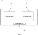
- FIG. 3 illustrates a NVDIMM 40 according to an embodiment.
- the NVDIMM 40 may include a flash memory 41, a DRAM 42 and a controller 43.
- the NVDIMM 40 may include a capacitor or battery (not shown) to store energy. When power is lost, data stored in the DRAM 42 may be copied to the flash memory 41. When power is restored, the data stored in the flash memory 41 may be transferred to the DRAM 42.
- FIG. 4 shows a method of operating a processor according to an example embodiment.
- the method 50 may be implemented as one or more modules in a set of logic instructions stored in a machine- or computer-readable storage medium such as random access memory (RAM), read only memory (ROM), programmable ROM (PROM), firmware, flash memory, etc., in configurable logic such as, for example, programmable logic arrays (PLAs), field programmable gate arrays (FPGAs), complex programmable logic devices (CPLDs), in fixed-functionality hardware logic using circuit technology such as, for example, application specific integrated circuit (ASIC), complementary metal oxide semiconductor (CMOS) or transistor-transistor logic (TTL) technology, or any combination thereof.
- PLAs programmable logic arrays
- FPGAs field programmable gate arrays
- CPLDs complex programmable logic devices
- ASIC application specific integrated circuit
- CMOS complementary metal oxide semiconductor
- TTL transistor-transistor logic
- computer program code to carry out operations shown in method 50 may be written in any
- the power consumption of one or more non-volatile RAMs and one or more volatile RAMs is monitored.
- a voltage regulator for example, voltage regulator 32 illustrated in FIG. 2 , coupled to the one or more non-volatile RAMs and volatile RAMs, is controlled.
- the processor 35 may use precompiled code (p-code) to communicate with a memory controller (not shown) in the processor 35 illustrated in FIG. 2 , to throttle the memory modules 33 illustrated in FIG. 2 in order to reduce the power of the memory modules 33 to a value below a threshold value of the RAPL.
- Techniques described herein may therefore provide a methodology for obtaining cost-optimized RAPL implementation with NVDIMMs.
- the methodology may be used in Crystal Ridge, NVDIMM, and Purley platforms.
- S3 support for DDR4/DDR4L would require board logic to switch between the main power rail (e.g., 12V) and standby power, and (2) NVDIMM requires that no power is supplied to the NVDIMM during the S3 power state.
- processing refers to the action and/or processes of a computer or computing system, or similar electronic computing device, that manipulates and/or transforms data represented as physical quantities (e.g., electronic) within the computing system's registers and/or memories into other data similarly represented as physical quantities within the computing system's memories, registers or other such information storage, transmission or display devices.
- physical quantities e.g., electronic
- Coupled may be used herein to refer to any type of relationship, direct or indirect, between the components in question, and may apply to electrical, mechanical, fluid, optical, electromagnetic, electromechanical or other connections.
- first”, second, etc. may be used herein only to facilitate discussion, and carry no particular temporal or chronological significance unless otherwise indicated.
Landscapes
- Engineering & Computer Science (AREA)
- Theoretical Computer Science (AREA)
- Physics & Mathematics (AREA)
- General Engineering & Computer Science (AREA)
- General Physics & Mathematics (AREA)
- Power Engineering (AREA)
- Computer Hardware Design (AREA)
- Power Sources (AREA)
- Microelectronics & Electronic Packaging (AREA)
Abstract
Description
- The present application claims the benefit of priority to
U.S. Non-Provisional Patent Application No. 14/748,728 filed on June 24, 2015 - Embodiments generally relate to memory structures. More particularly, embodiments relate to the cost optimized power management of Double Data Rate Fourth Generation (DDR4) memory and Non-Volatile Dual Inline Memory Modules (NVDIMMs) in the same platform in a sleep state.
- Computing platforms, such as workstations and desktop computers that support an S3 sleep state via an interface defined, for example, in the Advanced Configuration and Power Interface (ACPI, e.g., ACPI Specification, Rev. 5.0a, December 6, 2011) specification, may require different S3 flows for Double Data Rate Fourth Generation (DDR4) memory modules and Non-Volatile Dual Inline Memory Modules (NVDIMMs), due to different S3 power rail requirements. For S3 support, power to the DDR4 memory modules will be switched to standby power, while the power of the NVDIMM memory modules will be turned off. In the related art, multiple switches have to be used to individually control the DDR4 memory modules and the NVDIMM memory modules, thus adding cost.
- The various advantages of the embodiments will become apparent to one skilled in the art by reading the following specification and appended claims, and by referencing the following drawings, in which:
-
FIG. 1 is an illustration of a related art power management system; -
FIG. 2 is an illustration of a power management system according to an embodiment; -
FIG. 3 is an illustration of a NVDIMM according to an embodiment; and -
FIG. 4 shows a flowchart of an example of a method of operating a processor according to an embodiment. -
FIG. 1 is a view illustrating a power management system of the related art. Thepower management system 20 includes apower supply 21, amain switch 22,12v monitoring sensors 23, memory voltage regulators (VR) 24,non-volatile RAMs 25 andadditional switches 26. - In an S3 sleep state, the power to the volatile RAMs may enter a standby state (e.g., "5VSTDBY"). The power to the
non-volatile RAMs 25, on the other hand, may be turned off in the S3 sleep state. Thus, when the system is transitioning to the S3 state, theadditional switches 26 connected to thenon-volatile RAMs 25 may be turned off (e.g., opened). - Since each of the
non-volatile RAMs 25 are controlled by theadditional switches 26, the cost of the system may increase in the illustrated example. -
FIG. 2 illustrates apower management system 30 having a hybrid memory support apparatus according to an example embodiment. Thepower management system 30 may include at least one sensor 31 (e.g., 12V), at least onevoltage regulator 32,memory modules 33, asingle switch 34, and aprocessor 35. - In one example, the
power management system 30 runs on a Running Average Power Limit (RAPL) platform that uses sensors to obtain fine grained energy models. The RAPL allows theprocessor 35 to monitor power consumption of various components, including non-volatile RAMs. If the power consumption is higher than a predetermined level, the power consumption of thememory modules 33 is throttled down. - The
memory modules 33 may include a plurality ofslots 36. A plurality of volatile RAMs and non-volatile RAMs may be inserted into each of theslots 36. The non-volatile RAMs may include one or more non-volatile dual inline memory modules (NVDIMMs), and the volatile RAMs may include one or more double data rate (DDR) memory modules. The NVDIMMs may be memory modules that retain content when power is removed by unexpected power loss or after a system crash. - The illustrated
voltage regulators 32 automatically control the voltage of the components of thememory modules 33. Thevoltage regulators 32 may include a plurality ofregisters 37 to store voltage information and current information of each of the respective volatile RAMs and non-non-volatile RAMs. Theprocessor 35 may access each of theregisters 37 to obtain the voltage and current information of the respective volatile RAMS and non-non-volatile RAMs, and determines the amount of current that is being consumed by the system. - The
voltage registers 32 may be VR13 (voltage regulator series 13) regulators, although any other suitable type of regulator may be used. - The
sensor 31 may be an input sensor (e.g., 12V) that senses or measures the power consumption of the non-volatile RAMs and the volatile RAMs. Information from the illustratedsensor 31 is fed to theindividual registers 37 of thevoltage regulator 32 over a vendorspecific interface 36. Theprocessor 35 may then access each of theregisters 37 to obtain current and voltage information for each of the non-volatile RAMs and the volatile RAMs. - Specifically, the
processor 35 may accessspecific registers 37 in thevoltage regulators 32 to obtain power consumption of each of the NVDIMM memory modules and the DDR memory modules. The processor may sum the power consumption of each memory, and determine if the total consumed power exceeds a predetermined threshold. If the total power consumed by the memories exceeds the predetermined threshold, the processor throttles down the power to the system. - The
processor 35 may use precompiled code (p-code) to access the plurality ofregisters 37 in the voltage regulator to obtain the power consumption information of one or more of the non-volatile RAM, (or NVDIMM), and the volatile RAM, or DDR memory. The power consumption information for the non-volatile RAM, (or NVDIMM), may be stored separately from the power consumption information for the volatile RAM (or DDR memory). For example, a first set of one ormore registers 37 may store power consumption of the non-volatile RAM and a second set of one ormore registers 37 may store power consumption of the volatile RAM. The p-code in theprocessor 35 may therefore determine whichregister 37 in thevoltage regulator 32 should be accessed to obtain the power consumption information, and access each individual register to obtain power consumption information. - Instead of having multiple switches individually control each of the non-volatile RAMs as discussed above with regard to the related art, the exemplary embodiment uses the
single switch 34 to regulate the voltage of the non-volatile RAMs. The single 34 may be an S3 power switch, wherein when the system transitions to an S3 state, the power supply may be shut off. Accordingly, no power is supplied to the non-volatile RAM, in the illustrated example. - As illustrated in
FIG. 2 , thesensors 31 are connected in front of theswitch 34. Specifically, an output of thesensors 31 is connected to an input of theswitch 34. Accordingly, when the sleep state is switched to an S3 state, standby power is transmitted to thevoltage regulators 32, and the main power is shut off. Accordingly, in addition to the main power to the volatile RAMs being shut off, the main power to the non-volatile RAMs is also shut off. -
FIG. 3 illustrates a NVDIMM 40 according to an embodiment. The NVDIMM 40 may include aflash memory 41, aDRAM 42 and acontroller 43. The NVDIMM 40 may include a capacitor or battery (not shown) to store energy. When power is lost, data stored in theDRAM 42 may be copied to theflash memory 41. When power is restored, the data stored in theflash memory 41 may be transferred to theDRAM 42. -
FIG. 4 shows a method of operating a processor according to an example embodiment. Themethod 50 may be implemented as one or more modules in a set of logic instructions stored in a machine- or computer-readable storage medium such as random access memory (RAM), read only memory (ROM), programmable ROM (PROM), firmware, flash memory, etc., in configurable logic such as, for example, programmable logic arrays (PLAs), field programmable gate arrays (FPGAs), complex programmable logic devices (CPLDs), in fixed-functionality hardware logic using circuit technology such as, for example, application specific integrated circuit (ASIC), complementary metal oxide semiconductor (CMOS) or transistor-transistor logic (TTL) technology, or any combination thereof. For example, computer program code to carry out operations shown inmethod 50 may be written in any combination of one or more programming languages, including an object oriented programming language such as C, JAVA or the like. - In the illustrated
processing block 51, the power consumption of one or more non-volatile RAMs and one or more volatile RAMs is monitored. On the basis of the detected power consumption, in processing block 52 a voltage regulator, for example,voltage regulator 32 illustrated inFIG. 2 , coupled to the one or more non-volatile RAMs and volatile RAMs, is controlled. Theprocessor 35 may use precompiled code (p-code) to communicate with a memory controller (not shown) in theprocessor 35 illustrated inFIG. 2 , to throttle thememory modules 33 illustrated inFIG. 2 in order to reduce the power of thememory modules 33 to a value below a threshold value of the RAPL. -
- Example 1 may include a power management system comprising a sensor to monitor a power consumption of a non-volatile random access memory (RAM) and a volatile RAM, a switch, connected to an output of the sensor, to control power to the non-volatile RAM, a voltage regulator to regulate a voltage of the non-volatile RAM and the volatile RAM, memory slots to receive the non-volatile RAM and the volatile RAM; and a processor to receive information from the sensor, and control the voltage regulator based on the received sensor information.
- Example 2 may include the system of claim 1, further comprising a vendor specific interface between the sensor and the voltage regulator to transfer information between the sensor and the voltage regulator.
- Example 3 may include the system of claim 1, wherein the voltage regulator comprises a plurality of registers to store power consumption information of the non-volatile RAM and the volatile RAM
- Example 4 may include the system of claim 1, wherein the plurality of registers includes: a first set of one or more registers to store power consumption of the non-volatile RAM; and a second set of one or more registers to store power consumption of the volatile RAM.
- Example 5 may include the system of claim 4, wherein the processor includes precompiled code (p-code) to access the plurality of registers in the voltage regulator to obtain the power consumption information of one or more of the non-volatile RAM and the volatile RAM
- Example 6 may include the system of any one of claims 1 to 5, wherein the non-volatile RAM includes one or more non-volatile dual inline memory modules (NVDIMMs), and the volatile RAM includes one or more double data rate (DDR) memory modules.
- Example 7 may include an apparatus comprising a sensor to monitor a power consumption of a non-volatile random access memory (RAM) and a volatile RAM; a switch, connected to an output of the sensor, to control power to the non-volatile RAM; and a voltage regulator to regulate a voltage of the non-volatile RAM and the volatile RAM based on the power consumption.
- Example 8 may include the apparatus of claim 7, wherein the voltage regulator comprises a plurality of registers to store power consumption information of the non-volatile RAM and the volatile RAM.
- Example 9 may include the apparatus of claim 7, wherein the voltage regulator comprises a plurality of registers to store power consumption information of the non-volatile RAM and the volatile RAM.
- Example 10 may include the apparatus of claim 9, wherein the plurality of registers include a first set of one or more registers to store power consumption of the non-volatile RAM; and a second set of one or more registers to store power consumption of the volatile RAM.
- Example 11 may include the apparatus of claim 7, wherein the non-volatile RAM includes one or more non-volatile dual inline memory modules (NVDIMMs).
- Example 12 may include the method of claim 7, wherein the volatile RAM includes one or more double data rate (DDR) memory modules.
- Example 13 may include a method comprising monitoring a power consumption of a non-volatile random access memory (RAM) and a volatile RAM; and controlling a voltage regulator coupled to the non-volatile RAM and the volatile RAM based on the power consumption.
- Example 14 may include the method of claim 13, further comprising transferring information over a vendor specific interface between a sensor and a voltage regulator.
- Example 15 may include the method of claim 13, further comprising storing power consumption information of the non-volatile RAM and the volatile RAM in a plurality of registers of a voltage regulator.
- Example 16 may include the method of claim 15, further comprising storing power consumption information of the non-volatile RAM in a first set of one or more registers of the voltage regulator; and storing power consumption information of the volatile RAM in a second set of one or more registers of the voltage regulator.
- Example 17 may include the method of claim 15, further comprising using precompiled code (p-code) to access the power consumption information of one or more of the non-volatile RAM and the volatile RAM in the plurality of registers.
- Example 18 may include the method of claim 13, further comprising summing the power consumption of one or more of the non-volatile RA and the volatile RAM; determining if the total consumed power exceeds a predetermined threshold; and throttling down the power if the total consumed power exceeds the predetermined threshold.
- Example 19 may include the method of claim 13, wherein the non-volatile RAM includes one or more non-volatile dual inline memory modules (NVDIMMs), and the volatile RAM includes one or more double data rate (DDR) memory modules.
- Example 20 may include at least one non-transitory computer readable storage medium, comprising a set of instructions which, when executed by a computing device causes the computing device to monitor a power consumption of a non-volatile random access memory (RAM) and a volatile RAM; and control power to the non-volatile RAM by regulating a voltage of the non-volatile RAM and the volatile RAM based on the power consumption.
- Example 21 may include the at least one computer readable storage medium of
claim 20, wherein the instructions, when executed, cause the computing device to transfer information over a vendor specific interface between a sensor and a voltage regulator. - Example 22 may include the at least one computer readable storage medium of
claim 20, wherein the instructions, when executed, cause the computing device to store power consumption information of the non-volatile RAM and the volatile RAM in a plurality of registers of a voltage regulator. - Example 23 may include the at least one computer readable storage medium of
claim 22, wherein the instructions, when executed, cause the computing device to store power consumption information of the non-volatile RAM in a first set of one or more registers of the voltage regulator; and store power consumption information of the volatile RAM in a second set of one or more registers of the voltage regulator. - Example 24 may include the at least one computer readable storage medium of
claim 20, wherein the instructions, when executed, cause the computing device to use precompiled code (p-code) to access the power consumption information of one or more of the non-volatile RAM and the volatile RAM in the plurality of registers. - Techniques described herein may therefore provide a methodology for obtaining cost-optimized RAPL implementation with NVDIMMs. The methodology may be used in Crystal Ridge, NVDIMM, and Purley platforms. There are two key elements for S3 support that are considered (1) S3 support for DDR4/DDR4L would require board logic to switch between the main power rail (e.g., 12V) and standby power, and (2) NVDIMM requires that no power is supplied to the NVDIMM during the S3 power state.
- The same S3 and RAPL flows are allowed for both DDR4s and NVDIMMs in the same system without adding additional board logic for power switching between the main power rail and standby power.
- Unless specifically stated otherwise, it may be appreciated that terms such as "processing," "computing," "calculating," "determining," or the like, refer to the action and/or processes of a computer or computing system, or similar electronic computing device, that manipulates and/or transforms data represented as physical quantities (e.g., electronic) within the computing system's registers and/or memories into other data similarly represented as physical quantities within the computing system's memories, registers or other such information storage, transmission or display devices. The embodiments are not limited in this context.
- The term "coupled" may be used herein to refer to any type of relationship, direct or indirect, between the components in question, and may apply to electrical, mechanical, fluid, optical, electromagnetic, electromechanical or other connections. In addition, the terms "first", "second", etc. may be used herein only to facilitate discussion, and carry no particular temporal or chronological significance unless otherwise indicated.
- Those skilled in the art will appreciate from the foregoing description that the broad techniques of the embodiments can be implemented in a variety of forms. Therefore, while the embodiments of this have been described in connection with particular examples thereof, the true scope of the embodiments should not be so limited since other modifications will become apparent to the skilled practitioner upon a study of the drawings, specification, and following claims.
- The following section of the description relates to further examples. The numbered paragraphs in this section are not claims. The claims are set forth below in the later section headed "claims".
- 1. A power management system comprising:
- a sensor to monitor a power consumption of a non-volatile random access memory (RAM) and a volatile RAM;
- a switch, connected to an output of the sensor, to control power to the non-volatile RAM;
- a voltage regulator to regulate a voltage of the non-volatile RAM and the volatile RAM;
- one or more memory slots to receive the non-volatile RAM and the volatile RAM; and
- a processor to receive information from the sensor and control the voltage regulator based on the received information.
- 2. The system of clause 1, further comprising a vendor specific interface between the sensor and the voltage regulator to transfer information between the sensor and the voltage regulator.
- 3. The system of clause 1, wherein the voltage regulator comprises a plurality of registers to store power consumption information of the non-volatile RAM and the volatile RAM.
- 4. The system of clause 3, wherein the plurality of registers includes:
- a first set of one or more registers to store power consumption of the non-volatile RAM; and
- a second set of one or more registers to store power consumption of the volatile RAM.
- 5. The system of clause 4, wherein the processor includes precompiled code (p-code) to access the plurality of registers in the voltage regulator to obtain the power consumption information of one or more of the non-volatile RAM and the volatile RAM.
- 6. The system of any one of clauses 1 to 5, wherein the non-volatile RAM includes one or more non-volatile dual inline memory modules (NVDIMMs), and the volatile RAM includes one or more double data rate (DDR) memory modules.
- 7. A hybrid memory support apparatus comprising:
- a sensor to monitor a power consumption of a non-volatile random access memory (RAM) and a volatile RAM;
- a switch, connected to an output of the sensor, to control power to the non-volatile RAM; and
- a voltage regulator to regulate a voltage of the non-volatile RAM and the volatile RAM based on the power consumption.
- 8. The apparatus of clause 7, further comprising a vendor specific interface between the sensor and the voltage regulator to transfer information between the sensor and the voltage regulator.
- 9. The apparatus of clause 7, wherein the voltage regulator comprises a plurality of registers to store power consumption information of the non-volatile RAM and the volatile RAM.
- 10. The apparatus of clause 9, wherein the plurality of registers includes:
- a first set of one or more registers to store power consumption of the non-volatile RAM; and
- a second set of one or more registers to store power consumption of the volatile RAM.
- 11. The apparatus of any one of clauses 7 to 10, wherein the non-volatile RAM includes one or more non-volatile dual inline memory modules (NVDIMMs).
- 12. The method of any one of clauses 7 to 10, wherein the volatile RAM includes one or more double data rate (DDR) memory modules.
- 13. A method of operating a power management system, comprising:
- monitoring a power consumption of a non-volatile random access memory (RAM) and a volatile RAM; and
- controlling a voltage regulator coupled to the non-volatile RAM and the volatile RAM based on the power consumption.
- 14. The method of clause 13, further comprising transferring information over a vendor specific interface between a sensor and a voltage regulator.
- 15. The method of clause 13, further comprising storing power consumption information of the non-volatile RAM and the volatile RAM in a plurality of registers of a voltage regulator.
- 16. The method of clause 15, further comprising:
- storing power consumption information of the non-volatile RAM in a first set of one or more registers of the voltage regulator; and
- storing power consumption information of the volatile RAM in a second set of one or more registers of the voltage regulator.
- 17. The method of clause 15, further comprising using precompiled code (p-code) to access the power consumption information of one or more of the non-volatile RAM and the volatile RAM in the plurality of registers.
- 18. The method of clause 13, further comprising:
- summing the power consumption of one or more of the non-volatile RA and the volatile RAM;
- determining if the total consumed power exceeds a predetermined threshold; and
- throttling down the power if the total consumed power exceeds the predetermined threshold.
- 19. The method of any one of clauses 13 to 18, wherein the non-volatile RAM includes one or more non-volatile dual inline memory modules (NVDIMMs), and the volatile RAM includes one or more double data rate (DDR) memory modules.
- 20. At least one non-transitory computer readable storage medium, comprising a set of instructions which, when executed by a computing device causes the computing device to:
- monitor a power consumption of a non-volatile random access memory (RAM) and a volatile RAM; and
- control power to the non-volatile RAM by regulating a voltage of the non-volatile RAM and the volatile RAM based on the power consumption.
- 21. The at least one computer readable storage medium of
clause 20,
wherein the instructions, when executed, cause the computing device to transfer information over a vendor specific interface between a sensor and a voltage regulator. - 22. The at least one computer readable storage medium of
clause 20,
wherein the instructions, when executed, cause the computing device to store power consumption information of the non-volatile RAM and the volatile RAM in a plurality of registers of a voltage regulator. - 23. The at least one computer readable storage medium of
clause 22,
wherein the instructions, when executed, cause the computing device to:- store power consumption information of the non-volatile RAM in a first set of one or more registers of the voltage regulator; and
- store power consumption information of the volatile RAM in a second set of one or more registers of the voltage regulator.
- 24. The at least one computer readable storage medium of any one of
clauses 20 to 23, wherein the instructions, when executed, cause the computing device to use precompiled code (p-code) to access the power consumption information of one or more of the non-volatile RAM and the volatile RAM in the plurality of registers. - 25. A hybrid memory support apparatus comprising:
- means for monitoring a power consumption of a non-volatile random access memory (RAM) and a volatile RAM; and
- means for controlling a voltage regulator coupled to the non-volatile RAM and
the volatile RAM based on the power consumption.
Claims (10)
- A power management system comprising:a sensor to monitor a power consumption of non-volatile random access memories, RAMs, including one or more non-volatile inline memory modules, NVDIMM, and one or more volatile RAMs, including double data rate, DDR, memory modules;board logic to switch between a main power rail and standby power when the system transitions to an S3 sleep state, in which power to the DDRs is switched to standby power while no power is supplied to NVDIMMs, the board logic including a single power switch connected to an output of the sensor;a voltage regulator to regulate a voltage of the non-volatile RAMs;memory slots to receive the non-volatile RAMs and the volatile RAMs; anda processor to receive information from the sensor and control the voltage regulator based on the received information.
- The system of claim 1, further comprising a vendor specific interface between the sensor and the voltage regulator configured to transfer information between the sensor and the voltage regulator.
- The system of claim 1, wherein the voltage regulator comprises a plurality of registers configured to store power consumption information of the non-volatile RAMs and the volatile RAMs.
- The system of claim 3, wherein the plurality of registers includes:a first set of one or more registers configured to store power consumption of the non-volatile RAMs; anda second set of one or more registers configured to store power consumption of the volatile RAMs.
- The system of claim 4, wherein the processor includes precompiled code, p-code, to access the plurality of registers in the voltage regulator to obtain the power consumption information of one or more of the non-volatile RAMs and the volatile RAMs.
- A hybrid memory support apparatus for use in a power management system according to any of claims 1 to 5, the hybrid memory support apparatus comprising the sensor, the switch and the voltage regulator.
- A method of operating a power management system according to claim 1, comprising:monitoring a power consumption of the non-volatile RAMs and the volatile RAMs; andcontrolling the voltage regulator based on the power consumption.
- The method of claim 7, further comprising transferring information over a vendor specific interface between the sensor and the voltage regulator.
- The method of claim 10, further comprising storing power consumption information of the non-volatile RAMs and the volatile RAMs in a plurality of registers of the voltage regulator.
- At least one non-transitory computer readable storage medium, comprising a set of instructions which, when executed by a computing device, causes the computing device to carry out the method of claim 7, 8 or 9.
Applications Claiming Priority (3)
| Application Number | Priority Date | Filing Date | Title |
|---|---|---|---|
| US14/748,728 US9502082B1 (en) | 2015-06-24 | 2015-06-24 | Power management in dual memory platforms |
| EP16814888.0A EP3314364A4 (en) | 2015-06-24 | 2016-05-16 | ENERGY MANAGEMENT IN DOUBLE MEMORY PLATFORMS |
| PCT/US2016/032627 WO2016209408A1 (en) | 2015-06-24 | 2016-05-16 | Power management in dual memory platforms |
Related Parent Applications (1)
| Application Number | Title | Priority Date | Filing Date |
|---|---|---|---|
| EP16814888.0A Division EP3314364A4 (en) | 2015-06-24 | 2016-05-16 | ENERGY MANAGEMENT IN DOUBLE MEMORY PLATFORMS |
Publications (1)
| Publication Number | Publication Date |
|---|---|
| EP3842898A1 true EP3842898A1 (en) | 2021-06-30 |
Family
ID=57287734
Family Applications (2)
| Application Number | Title | Priority Date | Filing Date |
|---|---|---|---|
| EP20214883.9A Withdrawn EP3842898A1 (en) | 2015-06-24 | 2016-05-16 | Power management in dual memory platforms |
| EP16814888.0A Ceased EP3314364A4 (en) | 2015-06-24 | 2016-05-16 | ENERGY MANAGEMENT IN DOUBLE MEMORY PLATFORMS |
Family Applications After (1)
| Application Number | Title | Priority Date | Filing Date |
|---|---|---|---|
| EP16814888.0A Ceased EP3314364A4 (en) | 2015-06-24 | 2016-05-16 | ENERGY MANAGEMENT IN DOUBLE MEMORY PLATFORMS |
Country Status (4)
| Country | Link |
|---|---|
| US (1) | US9502082B1 (en) |
| EP (2) | EP3842898A1 (en) |
| CN (1) | CN107667326B (en) |
| WO (1) | WO2016209408A1 (en) |
Families Citing this family (8)
| Publication number | Priority date | Publication date | Assignee | Title |
|---|---|---|---|---|
| US11301015B2 (en) * | 2016-12-05 | 2022-04-12 | Agiga Tech Inc. | Multiport energy supply for a nonvolatile memory module |
| CN107066305B (en) * | 2017-05-11 | 2020-07-28 | 北京百度网讯科技有限公司 | Method and device for updating server firmware of server and server |
| US10890963B2 (en) * | 2017-11-24 | 2021-01-12 | Insyde Software Corp. | System and method for platform sleep state enhancements using non-volatile dual in-line memory modules |
| US10769082B2 (en) * | 2018-05-01 | 2020-09-08 | Integrated Device Technology, Inc. | DDR5 PMIC interface protocol and operation |
| US10776293B2 (en) * | 2018-05-01 | 2020-09-15 | Integrated Device Technology, Inc. | DDR5 RCD interface protocol and operation |
| US11126251B2 (en) * | 2019-03-01 | 2021-09-21 | Micron Technology, Inc. | Power management in memory |
| US11314315B2 (en) | 2020-01-17 | 2022-04-26 | Samsung Electronics Co., Ltd. | Performance control of a device with a power metering unit (PMU) |
| CN111427518B (en) * | 2020-04-24 | 2023-01-24 | 西安紫光国芯半导体有限公司 | Data protection method and NVDIMM |
Citations (4)
| Publication number | Priority date | Publication date | Assignee | Title |
|---|---|---|---|---|
| US20070283178A1 (en) * | 2006-06-06 | 2007-12-06 | Rakesh Dodeja | Predict computing platform memory power utilization |
| US20080320267A1 (en) * | 2007-06-22 | 2008-12-25 | Christoph Bilger | Memory Element, Data Processing System, Method for Setting Operating Parameters of a Memory and Computer Program |
| US20100138684A1 (en) * | 2008-12-02 | 2010-06-03 | International Business Machines Corporation | Memory system with dynamic supply voltage scaling |
| US20120185706A1 (en) * | 2011-12-13 | 2012-07-19 | Sistla Krishnakanth V | Method, apparatus, and system for energy efficiency and energy conservation including dynamic control of energy consumption in power domains |
Family Cites Families (14)
| Publication number | Priority date | Publication date | Assignee | Title |
|---|---|---|---|---|
| JPS573164A (en) * | 1980-06-04 | 1982-01-08 | Nippon Denso Co Ltd | Microcomputer control device |
| US6016017A (en) * | 1997-12-12 | 2000-01-18 | Motorola, Inc. | System for providing an uninterrupted supply voltage and method |
| US6327635B1 (en) * | 1999-03-30 | 2001-12-04 | Qlogic Corporation | Add-on card with automatic bus power line selection circuit |
| US20080082752A1 (en) * | 2006-09-29 | 2008-04-03 | Ram Chary | Method and apparatus for saving power for a computing system by providing instant-on resuming from a hibernation state |
| US7710075B1 (en) | 2007-01-31 | 2010-05-04 | Network Appliance, Inc. | Apparatus and implementation of a battery in a non volatile memory subsystem |
| US8093868B2 (en) | 2008-09-04 | 2012-01-10 | International Business Machines Corporation | In situ verification of capacitive power support |
| US8412880B2 (en) | 2009-01-08 | 2013-04-02 | Micron Technology, Inc. | Memory system controller to manage wear leveling across a plurality of storage nodes |
| JP5060574B2 (en) | 2010-03-16 | 2012-10-31 | 株式会社東芝 | Memory system |
| US8949502B2 (en) * | 2010-11-18 | 2015-02-03 | Nimble Storage, Inc. | PCIe NVRAM card based on NVDIMM |
| US9830954B2 (en) | 2011-03-23 | 2017-11-28 | Intel Corporation | Method and system for dynamic power management of memories |
| US8145929B2 (en) * | 2011-07-01 | 2012-03-27 | Intel Corporation | Stochastic management of power consumption by computer systems |
| US8862917B2 (en) * | 2011-09-19 | 2014-10-14 | Qualcomm Incorporated | Dynamic sleep for multicore computing devices |
| US9195291B2 (en) * | 2013-06-21 | 2015-11-24 | Apple Inc. | Digital power estimator to control processor power consumption |
| US9014637B1 (en) * | 2013-09-27 | 2015-04-21 | Intel Corporation | Dynamic switching frequency control of an on-chip or integrated voltage regulator |
-
2015
- 2015-06-24 US US14/748,728 patent/US9502082B1/en active Active
-
2016
- 2016-05-16 CN CN201680030137.9A patent/CN107667326B/en active Active
- 2016-05-16 EP EP20214883.9A patent/EP3842898A1/en not_active Withdrawn
- 2016-05-16 EP EP16814888.0A patent/EP3314364A4/en not_active Ceased
- 2016-05-16 WO PCT/US2016/032627 patent/WO2016209408A1/en not_active Ceased
Patent Citations (4)
| Publication number | Priority date | Publication date | Assignee | Title |
|---|---|---|---|---|
| US20070283178A1 (en) * | 2006-06-06 | 2007-12-06 | Rakesh Dodeja | Predict computing platform memory power utilization |
| US20080320267A1 (en) * | 2007-06-22 | 2008-12-25 | Christoph Bilger | Memory Element, Data Processing System, Method for Setting Operating Parameters of a Memory and Computer Program |
| US20100138684A1 (en) * | 2008-12-02 | 2010-06-03 | International Business Machines Corporation | Memory system with dynamic supply voltage scaling |
| US20120185706A1 (en) * | 2011-12-13 | 2012-07-19 | Sistla Krishnakanth V | Method, apparatus, and system for energy efficiency and energy conservation including dynamic control of energy consumption in power domains |
Also Published As
| Publication number | Publication date |
|---|---|
| US9502082B1 (en) | 2016-11-22 |
| WO2016209408A1 (en) | 2016-12-29 |
| EP3314364A1 (en) | 2018-05-02 |
| CN107667326B (en) | 2021-10-01 |
| CN107667326A (en) | 2018-02-06 |
| EP3314364A4 (en) | 2019-02-20 |
Similar Documents
| Publication | Publication Date | Title |
|---|---|---|
| US9502082B1 (en) | Power management in dual memory platforms | |
| US9442557B2 (en) | Using a linear prediction to configure an idle state of an entity in a computing device | |
| US12451167B2 (en) | Power management integrated circuit with dual power feed | |
| US9471140B2 (en) | Valid context status retention in processor power mode management | |
| US9483103B2 (en) | Process state of a computing machine | |
| US10203749B2 (en) | Method and apparatus for saving power, including at least two power saving modes | |
| US10355520B2 (en) | System and method for achieving controlled load transition between power supplies and battery backup units | |
| CN106095037A (en) | Processing apparatus and related control method | |
| US20190205042A1 (en) | Configurable flush of data from volatile memory to non-volatile memory | |
| EP3039506A1 (en) | Power management in a circuit | |
| US20120278542A1 (en) | Computer system and sleep control method thereof | |
| US20120290852A1 (en) | System and method for voltage regulator optimization through predictive transient warning | |
| US9256278B2 (en) | Devices and methods for multi-core memory | |
| US20170097673A1 (en) | Computer system and method providing both main and auxiliary power over a single power bus | |
| JP7785642B2 (en) | MEMORY SYSTEM AND POWER CONTROL CIRCUIT | |
| EP2795423B1 (en) | Apparatus and method for managing power in a computing system | |
| KR102608610B1 (en) | Enables functions of a memory device in multiple phases | |
| US20140361749A1 (en) | Control system and control method for charge level of battery | |
| US9372527B2 (en) | Data access management apparatus and data access management method | |
| US20260003504A1 (en) | Power Gating for Memory Physical Layers | |
| US20070242550A1 (en) | Device and method of controlling operation of a flash memory | |
| CN106528457B (en) | Programmable logic controller and method for saving data during power failure | |
| WO2017126130A1 (en) | Computer device and computer-readable storage medium |
Legal Events
| Date | Code | Title | Description |
|---|---|---|---|
| PUAI | Public reference made under article 153(3) epc to a published international application that has entered the european phase |
Free format text: ORIGINAL CODE: 0009012 |
|
| STAA | Information on the status of an ep patent application or granted ep patent |
Free format text: STATUS: THE APPLICATION HAS BEEN PUBLISHED |
|
| AC | Divisional application: reference to earlier application |
Ref document number: 3314364 Country of ref document: EP Kind code of ref document: P |
|
| AK | Designated contracting states |
Kind code of ref document: A1 Designated state(s): AL AT BE BG CH CY CZ DE DK EE ES FI FR GB GR HR HU IE IS IT LI LT LU LV MC MK MT NL NO PL PT RO RS SE SI SK SM TR |
|
| STAA | Information on the status of an ep patent application or granted ep patent |
Free format text: STATUS: REQUEST FOR EXAMINATION WAS MADE |
|
| 17P | Request for examination filed |
Effective date: 20211207 |
|
| RBV | Designated contracting states (corrected) |
Designated state(s): AL AT BE BG CH CY CZ DE DK EE ES FI FR GB GR HR HU IE IS IT LI LT LU LV MC MK MT NL NO PL PT RO RS SE SI SK SM TR |
|
| STAA | Information on the status of an ep patent application or granted ep patent |
Free format text: STATUS: EXAMINATION IS IN PROGRESS |
|
| 17Q | First examination report despatched |
Effective date: 20220620 |
|
| STAA | Information on the status of an ep patent application or granted ep patent |
Free format text: STATUS: THE APPLICATION IS DEEMED TO BE WITHDRAWN |
|
| 18D | Application deemed to be withdrawn |
Effective date: 20240420 |