EP3842851A1 - Pathological microscope, display module, control method and device, and storage medium - Google Patents
Pathological microscope, display module, control method and device, and storage medium Download PDFInfo
- Publication number
- EP3842851A1 EP3842851A1 EP19851573.6A EP19851573A EP3842851A1 EP 3842851 A1 EP3842851 A1 EP 3842851A1 EP 19851573 A EP19851573 A EP 19851573A EP 3842851 A1 EP3842851 A1 EP 3842851A1
- Authority
- EP
- European Patent Office
- Prior art keywords
- analysis
- component
- pathological
- model
- microscope
- Prior art date
- Legal status (The legal status is an assumption and is not a legal conclusion. Google has not performed a legal analysis and makes no representation as to the accuracy of the status listed.)
- Granted
Links
Images







Classifications
-
- G—PHYSICS
- G01—MEASURING; TESTING
- G01N—INVESTIGATING OR ANALYSING MATERIALS BY DETERMINING THEIR CHEMICAL OR PHYSICAL PROPERTIES
- G01N21/00—Investigating or analysing materials by the use of optical means, i.e. using sub-millimetre waves, infrared, visible or ultraviolet light
- G01N21/84—Systems specially adapted for particular applications
-
- G—PHYSICS
- G01—MEASURING; TESTING
- G01N—INVESTIGATING OR ANALYSING MATERIALS BY DETERMINING THEIR CHEMICAL OR PHYSICAL PROPERTIES
- G01N33/00—Investigating or analysing materials by specific methods not covered by groups G01N1/00 - G01N31/00
- G01N33/48—Biological material, e.g. blood, urine; Haemocytometers
- G01N33/50—Chemical analysis of biological material, e.g. blood, urine; Testing involving biospecific ligand binding methods; Immunological testing
- G01N33/53—Immunoassay; Biospecific binding assay; Materials therefor
- G01N33/575—Immunoassay; Biospecific binding assay; Materials therefor for cancer
-
- G—PHYSICS
- G02—OPTICS
- G02B—OPTICAL ELEMENTS, SYSTEMS OR APPARATUS
- G02B21/00—Microscopes
- G02B21/36—Microscopes arranged for photographic purposes or projection purposes or digital imaging or video purposes including associated control and data processing arrangements
- G02B21/364—Projection microscopes
-
- G—PHYSICS
- G02—OPTICS
- G02B—OPTICAL ELEMENTS, SYSTEMS OR APPARATUS
- G02B21/00—Microscopes
- G02B21/36—Microscopes arranged for photographic purposes or projection purposes or digital imaging or video purposes including associated control and data processing arrangements
- G02B21/365—Control or image processing arrangements for digital or video microscopes
-
- G—PHYSICS
- G02—OPTICS
- G02B—OPTICAL ELEMENTS, SYSTEMS OR APPARATUS
- G02B21/00—Microscopes
- G02B21/36—Microscopes arranged for photographic purposes or projection purposes or digital imaging or video purposes including associated control and data processing arrangements
- G02B21/365—Control or image processing arrangements for digital or video microscopes
- G02B21/367—Control or image processing arrangements for digital or video microscopes providing an output produced by processing a plurality of individual source images, e.g. image tiling, montage, composite images, depth sectioning, image comparison
-
- G—PHYSICS
- G06—COMPUTING OR CALCULATING; COUNTING
- G06T—IMAGE DATA PROCESSING OR GENERATION, IN GENERAL
- G06T7/00—Image analysis
- G06T7/0002—Inspection of images, e.g. flaw detection
- G06T7/0012—Biomedical image inspection
-
- G—PHYSICS
- G06—COMPUTING OR CALCULATING; COUNTING
- G06T—IMAGE DATA PROCESSING OR GENERATION, IN GENERAL
- G06T7/00—Image analysis
- G06T7/10—Segmentation; Edge detection
- G06T7/11—Region-based segmentation
-
- G—PHYSICS
- G16—INFORMATION AND COMMUNICATION TECHNOLOGY [ICT] SPECIALLY ADAPTED FOR SPECIFIC APPLICATION FIELDS
- G16H—HEALTHCARE INFORMATICS, i.e. INFORMATION AND COMMUNICATION TECHNOLOGY [ICT] SPECIALLY ADAPTED FOR THE HANDLING OR PROCESSING OF MEDICAL OR HEALTHCARE DATA
- G16H15/00—ICT specially adapted for medical reports, e.g. generation or transmission thereof
-
- G—PHYSICS
- G16—INFORMATION AND COMMUNICATION TECHNOLOGY [ICT] SPECIALLY ADAPTED FOR SPECIFIC APPLICATION FIELDS
- G16H—HEALTHCARE INFORMATICS, i.e. INFORMATION AND COMMUNICATION TECHNOLOGY [ICT] SPECIALLY ADAPTED FOR THE HANDLING OR PROCESSING OF MEDICAL OR HEALTHCARE DATA
- G16H30/00—ICT specially adapted for the handling or processing of medical images
- G16H30/20—ICT specially adapted for the handling or processing of medical images for handling medical images, e.g. DICOM, HL7 or PACS
-
- G—PHYSICS
- G06—COMPUTING OR CALCULATING; COUNTING
- G06T—IMAGE DATA PROCESSING OR GENERATION, IN GENERAL
- G06T2207/00—Indexing scheme for image analysis or image enhancement
- G06T2207/10—Image acquisition modality
- G06T2207/10056—Microscopic image
- G06T2207/10061—Microscopic image from scanning electron microscope
-
- G—PHYSICS
- G06—COMPUTING OR CALCULATING; COUNTING
- G06T—IMAGE DATA PROCESSING OR GENERATION, IN GENERAL
- G06T2207/00—Indexing scheme for image analysis or image enhancement
- G06T2207/20—Special algorithmic details
- G06T2207/20081—Training; Learning
-
- G—PHYSICS
- G06—COMPUTING OR CALCULATING; COUNTING
- G06T—IMAGE DATA PROCESSING OR GENERATION, IN GENERAL
- G06T2207/00—Indexing scheme for image analysis or image enhancement
- G06T2207/20—Special algorithmic details
- G06T2207/20084—Artificial neural networks [ANN]
-
- G—PHYSICS
- G06—COMPUTING OR CALCULATING; COUNTING
- G06T—IMAGE DATA PROCESSING OR GENERATION, IN GENERAL
- G06T2207/00—Indexing scheme for image analysis or image enhancement
- G06T2207/30—Subject of image; Context of image processing
- G06T2207/30004—Biomedical image processing
- G06T2207/30024—Cell structures in vitro; Tissue sections in vitro
-
- G—PHYSICS
- G06—COMPUTING OR CALCULATING; COUNTING
- G06T—IMAGE DATA PROCESSING OR GENERATION, IN GENERAL
- G06T2207/00—Indexing scheme for image analysis or image enhancement
- G06T2207/30—Subject of image; Context of image processing
- G06T2207/30004—Biomedical image processing
- G06T2207/30096—Tumor; Lesion
-
- Y—GENERAL TAGGING OF NEW TECHNOLOGICAL DEVELOPMENTS; GENERAL TAGGING OF CROSS-SECTIONAL TECHNOLOGIES SPANNING OVER SEVERAL SECTIONS OF THE IPC; TECHNICAL SUBJECTS COVERED BY FORMER USPC CROSS-REFERENCE ART COLLECTIONS [XRACs] AND DIGESTS
- Y02—TECHNOLOGIES OR APPLICATIONS FOR MITIGATION OR ADAPTATION AGAINST CLIMATE CHANGE
- Y02A—TECHNOLOGIES FOR ADAPTATION TO CLIMATE CHANGE
- Y02A90/00—Technologies having an indirect contribution to adaptation to climate change
- Y02A90/10—Information and communication technologies [ICT] supporting adaptation to climate change, e.g. for weather forecasting or climate simulation
Definitions
- This application relates to the field of microscope shooting imaging, and in particular, to a pathologic microscope, a display module, a control method and apparatus, and a storage medium.
- Pathological examination is a pathomorphological method used for examining pathologic changes in organs, tissues, or cells of a body.
- a doctor may cut a lesion tissue of a specific size, make a pathological section by adopting a pathologic histology method, and then observe the pathological section by using a pathologic microscope to observe a lesion.
- a pathological digital image of a pathological section may be obtained, a doctor determines whether a suspicious lesion area exists through the pathological digital image, and if so, the suspicious lesion area may be confirmed again in a pathological section image of a microscope field. Therefore, the suspicious lesion area may be found in the microscope field only by switching to the microscope field and taking a specific time, and therefore the pathologic microscope is inconvenient to use and poor in real-time performance in an observation process.
- an additional display module applicable to a pathologic microscope including: an image acquisition component, a control component, and an augment reality (AR) projection component; the image acquisition component being disposed on an incident optical path of the pathologic microscope, an input end of the control component being electrically connected to the image acquisition component, an output end of the control component being electrically connected to the AR projection component, and the AR projection component being disposed on an outgoing optical path of the pathologic microscope; the image acquisition component being configured to acquire a pathological digital image from the incident optical path, the control component being configured to perform artificial intelligence (AI) analysis on the pathological digital image, to generate AI analysis information, and the AR projection component being configured to project the AI analysis information into a microscopic field of the pathologic microscope on the outgoing optical path.
- AI artificial intelligence
- a pathologic microscope including a microscope body and an additional display module, the additional display module is the additional display module as described above, and the microscope body includes a first body part corresponding to an incident optical path and a second body part corresponding to an outgoing optical path.
- a display control method performed by a control component, the method including: obtaining a pathological digital image acquired by an image acquisition component from an incident optical path, performing AI analysis on the pathological digital image, to generate AI analysis information, and controlling an AR projection component to project the AI analysis information into a microscopic field of a pathologic microscope on an outgoing optical path.
- the performing AI analysis on the pathological digital image, to generate AI analysis information includes at least one of the following steps: obtaining at least one AI analysis model, determining a target AI analysis model corresponding to a use scenario of the pathological digital image in the at least one AI analysis model, invoking the target AI analysis model to perform the AI analysis on the pathological digital image, to generate the AI analysis information, transmitting the pathological digital image to a server, and receiving the AI analysis information transmitted by the server, the server storing an AI analysis model and being configured to perform the AI analysis on the pathological digital image by using the AI analysis model to obtain the AI analysis information.
- a tumor area detection AI model is determined as the target AI analysis model in a case that the use scenario of the pathological digital image is tumor area detection, and the tumor area detection AI model is invoked to perform the AI analysis on the pathological digital image to obtain tumor analysis information; and/or a cell detection AI model is determined as the target AI analysis model in a case that the use scenario of the pathological digital image is cell detection, and the cell detection AI model is invoked to perform the AI analysis on the pathological digital image to obtain cell detection information; and/or an infectious disease detection AI model is determined as the target AI analysis model in a case that the use scenario of the pathological digital image is infectious disease detection, and the infectious disease detection AI model is invoked to perform the AI analysis on the pathological digital image to obtain infectious disease detection information.
- the method further includes: recognizing a control instruction acquired from a speech signal of a speech acquisition component, and controlling an analysis process of the AI analysis according to the control instruction; selecting, in a case that the control instruction is a model selection instruction, the target AI analysis model according to the model selection instruction; and downloading, in a case that the control instruction is a model download instruction, at least one AI analysis model by using the network component, or downloading, in a case that the target AI analysis model is not stored, the target AI analysis model by using the network component.
- the method further includes: generating a pathological report in a case that the control instruction is a first generation instruction, the pathological report including the AI analysis information, or generating a case history report in a case that the control instruction is a second generation instruction, the case history report including the AI analysis information and patient information, the patient information being recognized from a text or a graphic code on a pathological section; and recognizing text content from the speech signal, and generating a doctor record in the pathological report or the case history report according to the text content.
- the method further includes at least one of the following steps: uploading the pathological report or the case history report to a first target device by using the network component, and uploading, by using the network component, a microscope image superimposed with the AI analysis information to a second target device or sharing, by using the network component, the microscope image superimposed with the AI analysis information to a preset sharing channel.
- the method further includes: controlling a speech playback component to play the AI analysis information.
- a display control apparatus configured into the control component, the apparatus including: an image obtaining module, configured to obtain a pathological digital image acquired by an image acquisition component from an incident optical path, an image analysis module, configured to perform AI analysis on the pathological digital image, to generate AI analysis information, and an image projection module, configured to control an AR projection component to project the AI analysis information into a microscopic field of a pathologic microscope on an outgoing optical path.
- the image analysis module includes: a model obtaining unit, configured to obtain at least one AI analysis model and determine a target AI analysis model corresponding to a use scenario of the pathological digital image; a model invoking unit, configured to invoke the target AI analysis model to perform the AI analysis on the pathological digital image, to generate the AI analysis information; an image sending unit, configured to send the pathological digital image to a server, the server storing an AI analysis model and being configured to perform the AI analysis on the pathological digital image by using the AI analysis model to obtain the AI analysis information; and/or an information receiving unit, configured to receive the AI analysis information sent by the server.
- a model obtaining unit configured to obtain at least one AI analysis model and determine a target AI analysis model corresponding to a use scenario of the pathological digital image
- a model invoking unit configured to invoke the target AI analysis model to perform the AI analysis on the pathological digital image, to generate the AI analysis information
- an image sending unit configured to send the pathological digital image to a server, the server storing an AI analysis model and being
- the model invoking unit includes: a tumor detection subunit, configured to determine a tumor area detection AI model as the target AI analysis model in a case that the use scenario of the pathological digital image is tumor area detection and invoke the tumor area detection AI model to perform the AI analysis on the pathological digital image to obtain tumor analysis information; and/or a cell detection subunit, configured to determine a cell detection AI model as the target AI analysis model in a case that the use scenario of the pathological digital image is cell detection and invoke the cell detection AI model to perform the AI analysis on the pathological digital image to obtain cell detection information; and/or an infectious disease detection subunit, configured to determine an infectious disease detection AI model as the target AI analysis model in a case that the use scenario of the pathological digital image is infectious disease detection and invoke the infectious disease detection AI model to perform the AI analysis on the pathological digital image to obtain infectious disease detection information.
- a tumor detection subunit configured to determine a tumor area detection AI model as the target AI analysis model in a case that the use scenario of the pathological digital image is tumor area detection and invoke the
- the apparatus further includes: a speech recognition module, configured to recognize a control instruction acquired from a speech signal of a speech acquisition component and control an analysis process of the AI analysis according to the control instruction.
- the speech recognition module is configured to select, in a case that the control instruction is a model selection instruction, the target AI analysis model according to the model selection instruction.
- the speech recognition module is configured to download, in a case that the control instruction is a model download instruction, at least one AI analysis model by using the network component, or download, in a case that the target AI analysis model is not stored, the target AI analysis model by using the network component.
- the apparatus further includes: a report generation module, configured to generate a pathological report in a case that the control instruction is a first generation instruction, the pathological report including the AI analysis information, or further configured to generate a case history report in a case that the control instruction is a second generation instruction, the case history report including the AI analysis information and patient information, the patient information being recognized from a text or a graphic code on a pathological section.
- the report generation module is configured to recognize text content from the speech signal and generate a doctor record in the pathological report or the case history report according to the text content.
- the apparatus further includes: a report uploading module, configured to upload the pathological report or the case history report to a first target device by using the network component; and/or an image uploading module, configured to upload, by using the network component, a microscope image superimposed with the AI analysis information to a second target device or share, by using the network component, the microscope image superimposed with the AI analysis information to a preset sharing channel.
- a report uploading module configured to upload the pathological report or the case history report to a first target device by using the network component
- an image uploading module configured to upload, by using the network component, a microscope image superimposed with the AI analysis information to a second target device or share, by using the network component, the microscope image superimposed with the AI analysis information to a preset sharing channel.
- the apparatus further includes: an information playback module, configured to control a speech playback component to play the AI analysis information.
- a computer-readable storage medium storing at least one instruction, and the at least one instruction being loaded and executed by a processor to implement the display control method as described above.
- a pathologic microscope is widely used in clinical diagnosis and scientific research.
- the pathomorphology features of organs, tissues, or cells of a body may be obtained through pathological section images, so that the cause, pathogenesis, and development process of pathological changes can be clarified, and the pathological tissues can be evaluated and diagnosed.
- a pathological section is analyzed and diagnosed by a professional doctor under a pathologic microscope.
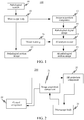
- FIG. 1 is a diagram of a working principle of a pathologic microscope 100 according to the related art.
- the pathologic microscope 100 includes a microscope body 10 including: an optical structure, and the microscope body 10 observes a pathological section 00 to obtain a pathological section image 01.
- the pathologic microscope 100 further includes an image acquisition component 12 and an AI analysis model 14.
- the image acquisition component 12 is configured to acquire a pathological digital image 02 of the pathological section 00 from an optical path of the microscope body 10
- the AI analysis model 14 is configured to perform algorithm analysis on the pathological digital image 02 to obtain an AI pathological section image 03.
- the AI pathological section image 03 may be displayed by using a liquid crystal display.
- a digital image needs to be first obtained from a pathologic microscope and then the digital image is analyzed through an AI algorithm.
- an image in a microscopic field is separated from an image processed by an AI algorithm, and a doctor needs to switch a visual field back and forth during entire observation of a pathological section image.
- the technology does not conform to a habit of directly observing a pathological section under the pathologic microscope by the doctor, and does not improve use convenience of the doctor.
- an AR technology is expected to be integrated into the pathologic microscope.
- a pathological section is directly analyzed in the microscopic field on the pathologic microscope, the pathological section is analyzed through the AI technology and corresponding AI analysis information is generated, and then the AI analysis information is directly integrated into the microscopic field of the pathologic microscope through the AR technology.
- FIG. 2 is a schematic structural diagram of a pathologic microscope 200 according to an exemplary embodiment of this application.
- the pathologic microscope 200 includes: a microscope body 20, an image acquisition component 21, a control component 22, and an AR projection component 23.
- An incident optical path and an outgoing optical path are formed on the microscope body 20, the image acquisition component 21 is disposed on the incident optical path, an input end of the control component 22 is electrically connected to the image acquisition component 21, an output end of the control component 22 is electrically connected to the AR projection component 23, and the AR projection component 23 is disposed on the outgoing optical path.
- An optical system on the microscope body 20 mainly includes an objective lens, an eyepiece, a reflector, a condenser, and the like, and a structure of the optical system on the microscope body 20 is not limited to this embodiment of this application. At least one of the lenses or reflectors forms the incident optical path and the outgoing optical path. In some embodiments, an optical path close to the objective lens is the incident optical path and an optical path close to the eyepiece is the outgoing optical path.
- the microscope body 20 includes a first body part corresponding to the incident optical path and a second body part corresponding to the outgoing optical path.
- the image acquisition component 21 is integrated into the first body part and the AR projection component 23 is integrated into the second body part.
- a first physical interface is formed on the first body part
- a first physical connector is formed on the image acquisition component 21
- the first physical connector of the image acquisition component 21 is connected to the first physical interface of the first body part.
- a second physical interface may be formed on the second body part
- a second physical connector may be formed on the AR projection component 23, and the second physical connector of the AR projection component 23 may be connected to the second physical interface of the second body part.
- the first physical interface and the second physical interface are at least one of a threaded interface, a socket, or a clamp interface.
- the image acquisition component 21 is configured to acquire a pathological digital image from the incident optical path.
- the control component 22 is configured to perform AI analysis on the pathological digital image to generate AI analysis information.
- the AI analysis information is result information obtained by analyzing the pathological digital image by using an AI analysis model.
- the AI analysis model may be stored in the control component 22 and may be configured to perform the AI analysis on the pathological digital image.
- the control component 22 is further configured to obtain at least one AI analysis model, determine a target AI analysis model corresponding to a use scenario of the pathological digital image, and invoke the target AI analysis model to perform the AI analysis on the pathological digital image to generate the AI analysis information.
- Different AI analysis models may have different analysis capabilities, and one or more AI analysis models may be disposed inside the control component 22.
- one or more AI analysis models may be disposed inside the control component 22.
- at least one of a tumor area detection AI model, a cell detection AI model, and an infectious disease detection AI model may be s simultaneously disposed in the control component 22.
- the control component 22 is further configured to determine the tumor area detection AI model as the target AI analysis model in a case that the use scenario of the pathological digital image is tumor area detection, and invoke the tumor area detection AI model to perform the AI analysis on the pathological digital image to obtain tumor analysis information.
- the tumor analysis information may include any one of breast cancer analysis information, bone cancer analysis information, and digestive tract cancer analysis information.
- the control component 22 is further configured to determine the cell detection AI model as the target AI analysis model in a case that the use scenario of the pathological digital image is cell detection, and invoke the cell detection AI model to perform the AI analysis on the pathological digital image to obtain cell detection information.
- the cell detection information may include any one of cell count information, mitotic cell detection information, and cell nuclear detection information.
- the control component 22 is further configured to determine the infectious disease detection AI model as the target AI analysis model in a case that the use scenario of the pathological digital image is infectious disease detection, and invoke the infectious disease detection AI model to perform the AI analysis on the pathological digital image to obtain infectious disease detection information.
- the infectious disease detection information may include any one of plasmodium egg detection information and acid-fast bacilli detection information.
- control component 22 further downloads an AI analysis model from other devices on a local area network or a wide area network. For example, the control component 22 downloads the AI analysis model from the other devices according to a current use scenario.
- the control component 22 is further configured to send the pathological digital image to a server, the server storing an AI analysis model and being configured to perform the AI analysis on the pathological digital image by using the AI analysis model, to obtain the AI analysis information.
- the control component is further configured to receive the AI analysis information sent by the server.
- the server may be a server, a server cluster including a plurality of servers, or a cloud server running on a cloud.
- the AR projection component 23 is configured to project the AI analysis information into a microscopic field of the microscope body 20 on the outgoing optical path.
- the AI analysis information includes at least one of a text, a curve, a background color, or an animation.
- an AI pathological image (or an AI pathological picture) can be formed.
- a region of interest may be marked in the AI pathological image, and may be marked through an arrow, a text, or the like.
- a region of interest may be marked by using a hot spot map.
- an image acquisition component acquires a pathological digital image
- a control component performs AI analysis on the pathological digital image to obtain AI analysis information
- an AR projection component projects the AI analysis information into a microscopic field of a microscope body, so that a doctor can directly observe a pathological section image and the AI analysis information in the microscopic field at the same time, and does not need to switch a visual field back and forth in the entire observation process, to make the observation process of the pathologic microscope simpler and more direct, thereby achieving a high real-time performance of the pathologic microscope in the use process.
- two disposing manners of the image acquisition component 21 are shown as examples for disposing the image acquisition component on the incident optical path of the microscope body 20.
- a top end of an objective tube 101 of the microscope body 20 is embedded with an image acquisition component 21, and an incident light 104 is split into one outgoing light 103 through a beam splitter prism 102 to enter an eyepiece tube 105.
- the incident light 104 is still transmitted to the top end of the objective tube 101 through the beam splitter prism 102, the image acquisition component 21 acquires the incident light 104, and the incident light 104 represents a picture observed by the microscope body 20.
- a side end of an objective tube 101 of the microscope body 20 is embedded with an image acquisition component 21, and an incident light 104 is split into one outgoing light 103 through a beam splitter prism 102 to enter an eyepiece tube 105.
- the incident light 104 is still transmitted to the top end of the objective tube 101 through the beam splitter prism 102, the incident light 104 is reflected at the top end of the objective tube 101 by using a reflecting mirror 106, the reflected incident light 104 is transmitted to the image acquisition component 21, the image acquisition component 21 acquires the incident light 104, and the incident light 104 represents a picture observed by the microscope body 20.
- the disposing manners of the image acquisition component 21 are merely examples for description, but the disposing manners of the image acquisition component 21 are not limited to this embodiment of this application.
- two projection principles of an AR projection component are shown as examples for disposing the AR projection component on the outgoing optical path of the microscope body 20.
- an eyepiece tube 105 of the microscope body 20 is embedded with an AR projection component 33, an embedding direction of the AR projection component 33 is opposite to a direction of eyes of a user, projection content 108 generates light deflection through reflection of a lens 107 in the eyepiece tube 105, the deflected projection content 108 is parallel to an outgoing light 103, and the outgoing light 103 is a picture observed by the microscope body 20.
- the deflected projection content 108 and the outgoing light 103 are superimposed as an AR pathological image (or AR pathological picture).
- an eyepiece tube 105 of the microscope body 20 is embedded with an AR projection component 33, an embedding direction of the AR projection component 33 is consistent with a direction of eyes of a user, projection content 108 generates light deflection through refraction of a lens 107 in the eyepiece tube 105, the deflected projection content 108 is parallel to an outgoing light 103, and the outgoing light 103 is a picture observed by the microscope body 20.
- the deflected projection content 108 and the outgoing light 103 are superimposed as an AR pathological image (or AR pathological picture).
- a speech interaction function is expected to be introduced in the pathologic microscope.
- a doctor may select and control corresponding functional modules in the pathologic microscope in a speech interaction manner.
- the pathologic microscope may further provide AI analysis information to the doctor in a speech prompt manner, for example, the pathologic microscope prompts a region of interest in a pathological section image to the doctor in a speech prompt manner.
- oral content of the doctor by be further converted into a pathological diagnosis report or into an electronic case history of a patient by using the speech interaction function.
- FIG. 7 is a schematic structural diagram of a pathologic microscope 200 according to another exemplary embodiment of this application.
- the pathologic microscope 200 in addition to including the microscope body 20, the image acquisition component 21, the control component 22, and the AR projection component 23, the pathologic microscope 200 further includes a speech acquisition component 51 connected to the control component 21.
- the speech acquisition component 51 is configured to acquire an external speech signal.
- the control component 22 is configured to recognize a control instruction of the speech signal and control an analysis process of AI analysis according to the control instruction.
- a microphone may be used as the speech acquisition component 51 to acquire an external speech signal and send the speech signal to the control component 22.
- the control component 22 recognizes content of the speech signal, and when the recognized content conforms to a preset control keyword, it is considered that a corresponding control instruction may be received.
- the control component 22 performs a corresponding control operation on the pathologic microscope 200 through the control instruction.
- a speech recognition engine is disposed in the control component 22, and the speech signal is recognized by using the speech recognition engine.
- the control instruction is a model selection instruction
- a target AI analysis model is selected according to the model selection instruction.
- the target AI analysis model includes a tumor area detection AI model, a cell detection AI model, and an infectious disease detection AI model.
- a user inputs a speech signal to the control component 22 by using the microphone 51, and the control component 22 recognizes the speech signal to obtain a control instruction.
- the control component 22 selects, according to the model selection instruction, a target AI analysis model corresponding to the actual use scenario.
- the speech recognition engine recognizes the sentence to obtain a recognition result.
- the control component 22 determines that "tumor detection model” is consistent with a preset keyword in the recognition result, it is determined that a control instruction is received.
- the control instruction is a model selection instruction, and controls to select a locally stored tumor area detection AI model for detection.
- control component 22 in a case that the control instruction is a first generation instruction, the control component 22 generates a pathological report according to the first generation instruction, the pathological report including AI analysis information.
- the pathological report is a report formed after a doctor inputs oral content through the microphone 51 according to the AI analysis information.
- the AI analysis information includes: appearance information of a pathological tissue and lesion information of a pathological cell, and the oral content includes pathological diagnosis of a doctor.
- a case history report is generated in a case that the control instruction is a second generation instruction.
- the case history report may include the AI analysis information and patient information, and the patient information may be recognized from a text or a graphic code on a pathological section, or inputted by the doctor by using the speech acquisition component.
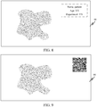
- the patient information may be recognized from a text on a pathological section 00. As shown in FIG. 8 , for example, the patient information includes name, age, and visit department. The patient information may further include other information. This is not limited in this embodiment.
- the patient information may be recognized from a graphic code on the pathological section 00, the graphic code may be a bar code or a QR code. As shown in FIG. 9 , the control component 22 obtains corresponding patient information through a QR code photographed by the image acquisition component 21.
- the patient information may include: at least one of name, gender, age, or occupation. This is not specifically limited to this embodiment.
- control component 22 is further configured to recognize text content from the speech signal and generate a doctor record in the pathological report or the case history report according to the text content.
- the control component 22 recognizes a speech signal, and expresses content of the speech signal in a text form to form text content corresponding to the speech signal.
- a doctor first dictates pathological diagnosis through the microphone 51, the control component 22 recognizes dictated content and expresses the dictated content in a text form, the doctor may then give a speech signal of generating a pathological report, the control component 22 recognizes the speech signal of the doctor to form a control instruction, the control instruction is a first generation instruction, and the pathologic microscope 200 generates the pathological report.
- a doctor first dictates doctor diagnosis through the microphone 51, the control component 22 recognizes dictated content and expresses the dictated content in a text form to improve case history report content, the doctor then gives a speech signal of generating a case history report, the control component 22 recognizes the speech signal of the doctor to form a control instruction, the control instruction is a second generation instruction, and the pathologic microscope 200 generates the case history report.
- the pathologic microscope 200 further includes: a network component 52 connected to the control component 22.
- control component 22 When a user inputs a control command to the control component 22 through the microphone 51, the control component 22 forms a control instruction, and the control instruction can control the network component 52.
- the control component 22 downloads at least one AI analysis model by using the network component 52, or in a case that a target AI analysis model is not stored, the control component 22 automatically downloads the target AI analysis model by using the network component 52.
- a user may issue an instruction of downloading an AI analysis model through the microphone 51, and when the control component 22 speech recognizes a model download instruction, controlling the network component 52 to download the AI analysis model, when receiving a model download instruction through speech recognition, the control component 22 controls the network component 52 to download the AI analysis model.
- the control component 22 may directly downloads the target AI analysis model by using the network component 52 without a model download instruction input by a user through a speech.
- the pathologic microscope 200 further includes: a network component 52 connected to the control component 22.
- the control component 22 is further configured to upload the pathological report or the case history report to a first target device through the network component 52.
- the control component 22 is further configured to upload, through the network component 52, an AI pathological image superimposed with the AI analysis information to a second target device or share, using the network component 52, an AI pathological image superimposed with the AI analysis information to a preset sharing channel.
- the first target device when the pathologic microscope 200 is used in a hospital, may include a hospital information system or a cloud server used inside the hospital, or when the pathologic microscope 200 is used in a scientific research laboratory, the first target device includes a laboratory information system or a cloud server used inside the laboratory, or when the pathologic microscope 200 is used in a school, the first target device includes at least one of a school teaching information system or a cloud server used inside a school.
- the second target device When the pathologic microscope 200 is used in the hospital, the second target device includes a pathological image database of the hospital information system, or when the pathologic microscope 200 is used in the scientific research laboratory, the second target device includes a pathological image database of the laboratory information system, or when the pathologic microscope 200 is used in the school teaching, the second target device includes a pathological image database of the school teaching information system.
- the preset sharing channel may include: at least one of an instant messaging platform, a medical communication platform, a journal of medical research, or a medical research forum.
- the pathologic microscope 200 further includes: a speech playback component 53 connected to the control component 22.
- control component 22 is further configured to send a pathological digital image to a server.
- the server may store an AI analysis model and configured to perform AI analysis on the pathological digital image by using the AI analysis model to obtain the AI analysis information.
- the control component 22 is further configured to receive the AI analysis information from the server.
- the server may be a server, a server cluster including a plurality of servers, or a cloud server running on a cloud.
- the control component 22 is further configured to control the speech playback component 53 to play the AI analysis information.
- the pathologic microscope 200 may play the AI analysis information by using the speech playback component 53.
- an image acquisition component acquires a pathological digital image
- a control component performs AI analysis on the pathological digital image to obtain AI analysis information
- an AR projection component projects the AI analysis information into a microscopic field of a microscope body, so that a doctor can directly observe a pathological section image and the AI analysis information in the microscopic field at the same time, and does not need to switch a visual field back and forth in the entire observation process.
- control component is further configured to obtain at least one AI analysis model.
- AI analysis model As factors such as the immersion reagent and the use scenario vary, the pathological section changes differently, and different analysis requirements are imposed in AI analysis.
- a single AI analysis model may not be able to adjust a model parameter according to an actual use scenario and ensure accuracy and stability in actual use.
- a plurality of different AI analysis models may be used to adapt to different actual use scenarios, thereby ensuring accuracy and stability of use.
- a speech acquisition component is connected to the control component.
- the speech acquisition component acquires an external speech signal and sends the speech signal to the control component, the control component forms a control instruction after recognizing the speech signal, the control instruction controls the pathologic microscope, and an operation of button control is omitted, thereby implementing a speech interaction operation of the pathologic microscope and improving man-machine interaction efficiency of a doctor.
- a doctor can smoothly use the pathologic microscope.
- a target AI analysis model is selected according to the model selection instruction.
- a user transmits a speech signal through a microphone, the control component recognizes the speech signal to form a control instruction, content of the control instruction is a model selection instruction, and a target AI analysis model corresponding to the actual use scenario is selected according to the model selection instruction.
- the control instruction is a model download instruction
- at least one AI analysis model is downloaded by using a network component, or in a case that a target AI analysis model is not stored, the target AI analysis model is downloaded by using a network component.
- the AI analysis model is obtained or updated, thereby ensuring that the AI analysis model can be applicable to a use scenario and ensuring accuracy and stability of a result.
- the control component may transmit a pathological digital image to a server, and an AI analysis model stored in the server may perform AI analysis on the pathological digital image. Thereafter, the control component may receive the obtained AI analysis information. Even if the control component does not store the AI analysis model, the control component may also obtain AI analysis information by using the server, thereby ensuring that the AI analysis model can be applicable to a use scenario and ensuring accuracy and stability of a result.
- the pathologic microscope when the control component the control instruction is to generate a report, the pathologic microscope automatically generates a pathological report or a case history report according to the AI analysis information, to integrate the pathological digital image and a doctor analysis result, thereby providing a basis for formulating a later treatment solution.
- control component further recognizes text content from the speech signal and generates a doctor record in the pathological report or the case history report the text content.
- Speech content recognized by the control component is expressed in a text form, and a doctor may perform professional diagnosis according to the AI analysis information, thereby avoiding complexity of typing on a keyboard.
- a network component further uploads or shares at least one of a pathological image, a pathological digital image, and an AI pathological image, and a corresponding report, and induction-arrangement and storage of pathological information are implemented, thereby reducing a task volume of a user of memorizing a large quantity of images and reducing repetitive memory.
- control component further controls a speech playback component to play the AI analysis information, so that a process in which a doctor views paper information or electronic information may be avoided, and the doctor only needs to listen to the played information to perform professional diagnosis, thereby improving diagnosis efficiency.
- the image acquisition component 21, the control component 22, and the network component 52 may be implemented by using an electronic device disposed outside the microscope body.
- the microscope body of the pathologic microscope 200 includes: a first body part corresponding to the incident optical path and a second body part corresponding to the outgoing optical path.
- a first physical interface is formed on the first body part, and the first physical interface may be a preset standard interface such as a threaded interface or a clip interface.
- the image acquisition component 21 may be a camera, a first physical connector is formed on the camera, and the first physical connector of the image acquisition component 21 is connected to the first physical interface on the first body part.
- a second physical interface is formed on the second body part, and the second physical interface may be a preset standard interface such as a threaded interface or a clip interface.
- a second physical connector is formed on the AR projection component 23, and the second physical connector of the AR projection component 23 is connected to the second physical interface on the second body part.
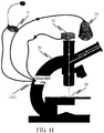
- the control component 22 and the network component 52 are further implemented by using a computer 1001, and a microphone is used as the speech acquisition component 51.
- the pathological section 00 is located on an object stage of the microscope body 20, the image acquisition component 21 is located on the incident optical path, and the image acquisition component 21 is electrically connected to an input end of the computer 1001.
- the AR projection component 23 is electrically connected to an output end of the computer 1001, and the AR projection component 23 is disposed on the outgoing optical path, and the outgoing optical path is located in an eyepiece tube of the microscope body 20.
- control component 22 (and at least one of the network component 52 or the speech playback component 53) may be manufactured into an integrated chip 1101.
- the integrated chip 1101 is integrally formed at a microscope arm of the microscope body, and a microphone is used as the speech acquisition component 51.
- the pathological section 00 is located on the object stage of the microscope body 20, the image acquisition component 21 is located on the incident optical path, and the image acquisition component 21 is electrically connected to an input end of the integrated chip 1101.
- the AR projection component 23 is electrically connected to an output end of the integrated chip 1101, and the AR projection component 23 is disposed on the outgoing optical path, and the outgoing optical path is located in the eyepiece tube of the microscope body 20.
- a system of the pathologic microscope needs to save and/or upload, through a network, files such as a pathological image, a pathological report, and a case history report in the process of processing a pathological section image, and further needs to download and/or update the AI analysis model through the network. Therefore, an implementation environment of the pathologic microscope requires an environment provided with a wired network or a wireless network.
- FIG. 12 is a diagram of an implementation environment of a pathologic microscope according to an exemplary embodiment of this application.
- the implementation environment includes: a pathologic microscope 200, a network 1201, a cloud server 1210, and a hospital information system 1220.
- the pathologic microscope 200 is manufactured by a manufacturer and provided to a doctor for use.
- the pathologic microscope 200 may be connected to the cloud server 1210 through a network, and may be further connected to the hospital information system 1220 through the network.
- the network 1201 may include a wired network or a wireless network.
- the network may be a dedicated wired network inside a hospital. An isolation effect that other people cannot access except that the doctor uses the dedicated wired network through an internal computer of the hospital to use the pathologic microscope may be implemented.
- the cloud server 1210 may be set up by a manufacturer of the pathologic microscope 200, and the manufacturer may publish an AI analysis model applicable to the pathologic microscope 200 and/or publish an updated version of the AI analysis model to the cloud server 1210.
- a purchaser or a user (for example, a hospital, a scientific institution, or a school) of the pathologic microscope 200 may download at least one of the AI analysis model or the updated version of the AI analysis model using the cloud server 1210. The download manner may be free or paid.
- the AI analysis model in the cloud server 1210 may be set up by technicians of the manufacturer.
- the cloud server 1210 may be used as a storage location of the AI analysis model, that is, an AI model library 1221 is disposed inside the cloud server 1210, and the AI model library 1221 is configured to store the AI analysis model.
- the pathologic microscope uploads the pathological digital image to the cloud server
- the AI model library 1221 in the cloud server is invoked, and a target AI analysis model is selected according to a use scenario to perform AI analysis to obtain AI analysis information. Then, the AI analysis information is transmitted back to the pathologic microscope.
- the AI analysis model in the cloud server 1210 may be set up by the technicians of the manufacturer, or the AI analysis model may be uploaded to the cloud server 1210 by a developer.
- the hospital information system 1220 includes a pathological report library 1222, a case history report library 1223, and a pathological image database 1224.
- an AI model library 1221 is disposed inside a computer, and the AI model library 1221 may be configured to download at least one of the published AI analysis model or updated version of the AI analysis model from the cloud server 1210 for use by various departments in the hospital, so that the doctor does not need to separately download from the cloud server 1210. For example, if the doctor directly downloads the at least one of the AI analysis model or the updated version of the AI analysis model from the cloud server 1210, the doctor needs to register an account and pay a corresponding fee.
- the doctor does not need to register an account additionally and does not need to pay a fee.
- an AI model library 1221 may be disposed inside a computer, and the AI model library 1221 may be configured to publish an AI analysis model developed by a researcher of the hospital for the pathologic microscope 200.
- the AI analysis model developed by the hospital may include at least one of the following models: an AI analysis model aiming at a pathological direction different from the AI analysis model provided by the manufacturer, an AI analysis model developed by the hospital superior to the AI analysis model provided by the manufacturer in some use scenarios, and an AI analysis model developed by the hospital that is not provided by the manufacturer.
- the AI model library 1221 disposed inside the computer may be configured to store the AI analysis model of the pathologic microscope 200.
- the pathologic microscope 200 is in use, a corresponding AI analysis model in the computer needs to be invoked for AI analysis, and the doctor may log in to an account of the hospital information system 1220 before using the pathologic microscope 200. In this case, the doctor invokes the corresponding AI analysis model directly from the AI model library 1221 through the pathologic microscope 200.
- the implementation of the AI model library 1221 is any one of the three types described above, or may include any two or all of them. This is not specifically limited to this embodiment.
- the pathologic microscope 200 includes a computer 1001, and the computer 1001 including a specific implementation of the control component and the network component.
- the computer 1001 uploads the pathological section image and/or a pathological digital image and/or an AI pathological image to the pathological image database 1224 of the hospital information system 1220 through the network 1201, to implement sharing of related information of the pathological section image and/or the pathological digital image and/or the AI pathological image and expand richness of the pathological image database 1224 inside the hospital.
- the pathologic microscope 200 generates a pathological report according to an operation of a user, for example, the pathologic microscope 200 generates a pathological report according to a speech instruction and oral content of a doctor, and then the pathologic microscope 200 uploads the pathological report to the pathological report library 1222 of the hospital information system 1220 through the network 1201, to expand the pathological report library 1222 inside the hospital and store the pathological report electronically.
- the pathologic microscope 200 generates a case history report according to an operation of a user, for example, the pathologic microscope 200 generates a case history report according to a speech instruction and oral content of a doctor, and then the pathologic microscope 200 uploads the case history report to the case history report library 1223 of the hospital information system 1220 through the network 1201, to expand the case history report library 1223 inside the hospital and store the case history report electronically.
- the pathological image database 1224, the pathological report library 1222, and the case history report library 1223 are all electronic storage of at least one of the pathological image, the pathological digital image, or the AI pathological image information, and the electronic storage may be used for subsequent statistical analysis and query, thereby expanding richness of the database.
- the electronic storage may be used for providing a learning case for a houseman to learn, and performing targeted diagnosis on treatment condition of a particular patient in the past
- the pathologic microscope 200 may be applied to a hospital application place, or may be applied to an application place such as a research institution or a school.
- the implementation environment is basically similar to the implementation environment mentioned in this embodiment. Details are not described herein.
- the AI analysis model may be trained by a technician of a hospital, or may be trained by a technician of a manufacturer of a pathologic microscope.
- the training process is shown in FIG. 13 .
- Step 1300 Use scenario.
- a technician determines a use scenario of an AI analysis model.
- the AI analysis model may be an AI model for tumor analysis, an AI model for cell detection analysis, or an AI model for infectious disease detection analysis. This is not limited in this embodiment, provided that the use scenario is possibly used by the pathologic microscope.
- the technician determines a pathological model image 1320 required for model training, and the pathological model image 1320 may be a sample image library.
- One use scenario may correspond to one group of pathological model images, and different use scenarios may correspond to different groups of pathological model images.
- Each pathological model image is manually or machine labeled with a corresponding calibration result, and the calibration result is used for indicating an actual analysis result generated manually or by other machines.
- the model training may be divided into: a training process and a test process.
- the m1 training images 1322 are used for training the AI analysis model during training, and the m2 test images 1324 are used for performing a performance test on the trained AI analysis model during test.
- the m1 training images 1322 may be referred to as a training image set
- the m2 test images 1324 may be referred to as a test image set.
- Step 1301. Construct an AI analysis model.
- the technician further constructs corresponding AI analysis models for different use scenarios.
- the AI analysis model is a neural network model for processing an image, and the neural network model may be a deep neural network (DNN), a convolutional neural network (CNN), a recurrent neural network (RNN), or the like. This is not limited in this embodiment of this application.
- DNN deep neural network
- CNN convolutional neural network
- RNN recurrent neural network
- the technician may set a network type, a quantity of network layers, a composition form of neurons of each layer of network, a type of a neuron adopted by each layer of network, and a connection relationship between adjacent network layers of the AI analysis model may be set according to different use scenarios. That is, different AI analysis models may have the same network type or different network types, the same quantity of network layers or different quantities of network layers, the same composition form of neurons of each layer of network or different composition forms of neurons of each layer of network, the same type of a neuron adopted by each layer of network or different types of neurons adopted by each layer of network, or the same connection relationship between adjacent network layers or different connection relationships between adjacent network layers. This is not limited in this embodiment.
- Step 1302. Set a training parameter.
- each layer of neurons in the AI analysis model has a respective neuron parameter (or weight).
- the technician may generate an initial parameter of each layer of neurons in a random manner, or may generate an initial parameter of each layer of neurons in a manner of setting an empirical value.
- the initial parameter is a neuron parameter of a neuron in the AI analysis model before training.
- Step 1303. Model training.
- Each training image 1322 in the training image set is sequentially inputted into an AI analysis model for training, the AI analysis model performs AI analysis on the training image 1322 to obtain a prediction result, the prediction result is compared with a calibration result of the training image 1322 to obtain an analysis error, and then back propagation is performed on the analysis error according to an error back propagation algorithm, to update a parameter of each layer of neurons of the AI analysis model.
- Step 1304. Determine whether a training data evaluation standard is reached.
- the technician sets a training data evaluation standard (also referred to as a training finishing condition).
- a training data evaluation standard is used so that a prediction error converges to an expected threshold.
- the training data evaluation standard is used so that a quantity of times of training iteration reaches a times threshold (for example, 10000).
- the model may determine whether the training data evaluation standard is reached is determined. When the training data evaluation standard is reached, step 1305 is performed, and when the training data evaluation standard is not reached, step 1303 is performed again.
- the training finishing condition is that a quantity of times of training iteration reaches 20000, when the quantity of times of training iteration reaches 20000, step 1305 may be performed; otherwise, a next iteration training process is repeated.
- Step 1305. Determine whether an evaluation data evaluation standard is reached.
- each test image 1324 in the test image set may be inputted into the trained AI analysis model for testing.
- the evaluation data is each test image in the test image set.
- the test data evaluation standard may be that an error between a test result and a calibration result of the test image is less than a preset condition, accuracy of a test result of the test image is greater than a preset threshold, or both a test speed and a test result of the test image reach an expected condition.
- the test data evaluation standard may be different according to different actual use scenarios. However, this is not limited to this embodiment.
- step 1306 is performed.
- Step 1306. Complete model training.
- the trained AI analysis model is determined as an AI analysis model that can be used online and is stored in an AI model library 1330.
- the AI model library may be an AI model library in the control component of the pathologic microscope, an AI model library in a health care system of a hospital, or an AI model library in a cloud server set by a manufacturer of the pathologic microscope.
- the pathologic microscope implements functions such as AI analysis and projection on a pathological image by controlling other components by the control component.
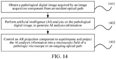
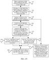
- FIG. 14 is a flowchart of a display control method according to an exemplary embodiment of this application. The method may be applied to the control component of the pathologic microscope provided by the embodiments, and the method includes the following steps:
- Step 1401. Obtain a pathological digital image acquired by an image acquisition component from an incident optical path.
- the image acquisition component is located on the incident optical path of a microscope body, acquires a pathological image of a pathological section on an object stage, and performs image preprocessing on the pathological image inside the image acquisition component, to obtain the pathological digital image.
- Step 1402. Perform AI analysis on the pathological digital image, to generate AI analysis information.
- the AI analysis information is result information obtained by analyzing the pathological digital image by using an AI analysis model.
- the AI analysis model is disposed inside the control component and is configured to perform the AI analysis on the pathological digital image.
- at least one AI analysis model is obtained, a target AI analysis model corresponding to a use scenario of the pathological digital image is determined.
- the target AI analysis model may be invoked to perform the AI analysis on the pathological digital image to generate the AI analysis information.
- the AI analysis model is disposed inside a server and is configured to perform the AI analysis on the pathological digital image.
- the control component sends the pathological digital image to a server.
- the server storing an AI analysis model, and the server is configured to perform the AI analysis on the pathological digital image by using the AI analysis model, to obtain the AI analysis information and send the AI analysis information to the control component.
- the control component receives the AI analysis information sent by the server.
- the server when the server sends the AI analysis information to the control component, it may be that after the control component sends a download request to the server, the server sends the AI analysis information to the control component according to the download request, or the server directly sends the AI analysis information to the control component after analyzing to obtain the AI analysis information.
- the process in which the server obtains the AI analysis information through the AI analysis may be similar to the process in which the control component obtains the AI analysis information through the AI analysis in the first manner. Details are not described herein again.
- the server may be a server, a server cluster including a plurality of servers, or a cloud server running on a cloud. In some embodiments, the server may be implemented as a cloud server shown in FIG. 12 .
- Step 1403. Control an AR projection component to project the AI analysis information into a microscopic field of a pathologic microscope on an outgoing optical path.
- the AI analysis information includes at least one of a text, a curve, a background color, or an animation. After the AI analysis information is superimposed with an image (or a picture) in the microscopic field, an AI pathological image (or an AI pathological picture) can be formed.
- the microscope body includes a first body part corresponding to the incident optical path and a second body part corresponding to the outgoing optical path.
- the image acquisition component is integrated into the first body part and the AR projection component is integrated into the second body part.
- a first physical interface is formed on the first body part, a first physical connector is formed on the image acquisition component, and the first physical connector of the image acquisition component is connected to the first physical interface of the first body part.
- a second physical interface is formed on the second body part, a second physical connector is formed on the AR projection component, and the second physical connector of the AR projection component is connected to the second physical interface of the second body part.
- the first physical interface and the second physical interface are at least one of a threaded interface, a socket, or a clamp interface.
- an image acquisition component acquires a pathological digital image
- a control component performs AI analysis on the pathological digital image to obtain AI analysis information
- an AR projection component projects the AI analysis information into a microscopic field of a microscope body, so that a doctor can directly observe a pathological section image and the AI analysis information in the microscopic field at the same time, and does not need to switch a visual field back and forth in the entire observation process, to make the observation process of the pathologic microscope simpler and more direct, thereby achieving a high real-time performance of the pathologic microscope in the use process.
- control component in addition to implementing the AI analysis and projection on the pathological image, is further configured to implement at least one of the functions such as generation of a pathological report and a case history report, download of the AI analysis model, and upload of the pathological image, the pathological report, or the case history report. Therefore, the control component has a control method to achieve a control purpose.
- FIG. 15 is a flowchart of a display control method according to another exemplary embodiment of this application. The method may be applied to the control component of the pathologic microscope, and the method includes the following steps:
- Step 1501. Obtain a pathological digital image acquired by an image acquisition component from an incident optical path.
- Step 1502. Recognize a control instruction acquired from a speech signal of a speech acquisition component, and control an analysis process of AI analysis according to the control instruction.
- a microphone may be used as the speech acquisition component to acquire an external speech signal and send the speech signal to the control component.
- the control component recognizes content of the speech signal, and when the recognized content conforms to a preset control keyword, it is considered that a corresponding control instruction is received.
- the control component performs a corresponding control operation on the pathologic microscope according to the control instruction.
- a speech recognition engine is disposed in the control component, and the speech signal is recognized by using the speech recognition engine.
- the control instruction is a model selection instruction
- a target AI analysis model is selected according to the model selection instruction.
- the target AI analysis model includes a tumor area detection AI model, a cell detection AI model, and in infectious disease detection AI model.
- a user inputs a speech signal to the control component by using the microphone, and the control component recognizes the speech signal to obtain a control instruction.
- the control component selects, according to the model selection instruction, a target AI analysis model corresponding to the actual use scenario.
- control component When a user issues a control command through the microphone, the control component forms a control instruction, and the control instruction can control a network component.
- control component downloads at least one AI analysis model using the network component, or in a case that the target AI analysis model is not stored, the control component automatically downloads the target AI analysis model by using the network component.
- Step 1503. Perform AI analysis on the pathological digital image to generate AI analysis information.
- step 1503 For a description of step 1503, reference may be made to step 1402.
- a server may be a server, a server cluster including a plurality of servers, or a cloud server running on a cloud.
- the server may be implemented as a cloud server shown in FIG. 12 .
- Step 1504. Control a speech playback component to play the AI analysis information.
- the pathologic microscope may play the AI analysis information by using the speech playback component.
- Step 1505. Control an AR projection component to project the AI analysis information into a microscopic field of a pathologic microscope on an outgoing optical path.
- Step 1506 Generate a pathological report in a case that the control instruction is a first generation instruction.
- the pathological report includes AI analysis information.
- the pathological report is a report formed after a doctor inputs oral content through the microphone 51 according to the AI analysis information.
- the AI analysis information includes: appearance information of a pathological tissue and lesion information of a pathological cell, and the oral content includes pathological diagnosis of a doctor.
- Step 1507 Generate a case history report in a case that the control instruction is a second generation instruction.
- the case history report includes the AI analysis information and patient information, and the patient information is recognized from a text or a graphic code on a pathological section, or may be inputted by the doctor by using the speech acquisition component.
- text content is recognized from a speech signal and a doctor record in the pathological report or the case history report is generated according to the text content.
- the control component recognizes a speech signal, and expresses content of the speech signal in a text form to form text content corresponding to the speech signal.
- Step 1508 Upload the pathological report or the case history report to a first target device using a network component.
- the first target device when the pathologic microscope is used in a hospital, the first target device includes a hospital information system or a cloud server used inside the hospital, or when the pathologic microscope is a used in a scientific research laboratory, the first target device includes a laboratory information system or a cloud server used inside a laboratory, or when the pathologic microscope is used in school teaching, the first target device includes a school teaching information system or a cloud serve used inside a school.
- Step 1509 Upload, through the network component, a microscope image superimposed with the AI analysis information to a second target device or sharing, through the network component, the microscope image superimposed with the AI analysis information to a preset sharing channel.
- the second target device when the pathologic microscope is used in the hospital, the second target device includes a pathological image database of the hospital information system, or when the pathologic microscope is used in the scientific research laboratory, the second target device includes a pathological image database of the laboratory information system, or when the pathologic microscope is used in school, the second target device includes a pathological image database of the school teaching information system.
- the preset sharing channel includes: at least one of an instant messaging platform, a medical communication platform, a journal of medical research, or a medical research forum.
- an image acquisition component acquires a pathological digital image
- a control component performs AI analysis on the pathological digital image to obtain AI analysis information
- an AR projection component projects the AI analysis information into a microscopic field of a microscope body, so that a doctor can directly observe a pathological section image and the AI analysis information in the microscopic field at the same time, and does not need to switch a visual field back and forth in the entire observation process, to make the observation process of the pathologic microscope simpler and more direct, thereby achieving a high real-time performance of the pathologic microscope in the use process.
- the control component may be further configured to obtain at least one AI analysis model.
- factors such as the immersion reagent and the use scenario vary, the pathological section changes differently, and different analysis requirements may be imposed on the AI analysis.
- a single AI analysis model cannot adjust a model parameter according to an actual use scenario and cannot ensure accuracy and stability in actual use.
- a plurality of different AI analysis models can adapt to different actual use scenarios, thereby ensuring accuracy and stability of use.
- a speech acquisition component is connected to the control component.
- the speech acquisition component acquires an external speech signal and sends the speech signal to the control component, the control component forms a control instruction after recognizing the speech signal, the control instruction controls the pathologic microscope, and an operation of button control is omitted, thereby implementing a speech interaction operation of the pathologic microscope and improving man-machine interaction efficiency of a doctor.
- a doctor can smoothly use the pathologic microscope.
- a target AI analysis model is selected according to the model selection instruction.
- a user transmits a speech signal through a microphone, the control component recognizes the speech signal to form a control instruction, content of the control instruction is a model selection instruction, and a target AI analysis model corresponding to the actual use scenario is selected according to the model selection instruction.
- the control instruction is a model download instruction
- at least one AI analysis model is downloaded by using a network component, or in a case that a target AI analysis model is not stored, the target AI analysis model is downloaded through a network component.
- the AI analysis model is obtained or updated, thereby ensuring that the AI analysis model can be applicable to a use scenario and ensuring accuracy and stability of a result.
- the control component sends a pathological digital image to a server, an AI analysis model stored in the server performs AI analysis on the pathological digital image, and the control component receives obtained AI analysis information. Even if the control component does not store the AI analysis model, the control component may also obtain AI analysis information by using the server, thereby ensuring that the AI analysis model can be applicable to a use scenario and ensuring accuracy and stability of a result.
- the pathologic microscope when the control instruction is to generate a report, automatically generates a pathological report or a case history report according to the AI analysis information, to integrate the pathological digital image and a doctor analysis result, thereby providing a basis for formulating a later treatment solution.
- the control component further recognizes text content from the speech signal and generates a doctor record in the pathological report or the case history report according to the text content.
- Speech content recognized by the control component is expressed in a text form, and a doctor may perform professional diagnosis according to the AI analysis information, thereby avoiding complexity of typing on a keyboard.
- a network component further uploads or shares at least one of a pathological image, a pathological digital image, or an AI pathological image, and a corresponding report, and induction-arrangement and storage of pathological information are implemented, thereby reducing a task volume of a user of memorizing a large quantity of images and reducing repetitive memory.
- control component further controls a speech playback component to play the AI analysis information, so that a process in which a doctor views paper information or electronic information may be avoided, and the doctor only needs to listen to the played information to perform professional diagnosis, thereby improving diagnosis efficiency.
- FIG. 16 is a schematic diagram of a display control apparatus according to an exemplary embodiment of this application.
- the apparatus may be configured in the control component of the pathologic microscope provided in the method embodiments, and the apparatus includes:
- AI analysis models have different analysis capabilities, and one or more AI analysis models may be disposed inside the model invoking unit 1631. At least one of a tumor area detection AI model, a cell detection AI model, and an infectious disease detection AI model may be disposed in the model invoking unit 1632.
- the tumor area detection AI model, the cell detection AI model, and the infectious disease detection AI model are simultaneously disposed in the model invoking unit 1632.
- the model invoking unit 1632 includes a tumor detection subunit 1731, a cell detection subunit 1732, and an infectious disease detection subunit 1733.
- the tumor detection subunit 1731 is further configured to determine the tumor area detection AI model as a target AI analysis model in a case that a use scenario of the pathological digital image is tumor area detection, and invoke the tumor area detection AI model to perform the AI analysis on the pathological digital image to obtain tumor analysis information.
- the cell detection subunit 1732 is further configured to determine the cell detection AI model as a target AI analysis model in a case that a use scenario of the pathological digital image is cell detection, and invoke the cell detection AI model to perform the AI analysis on the pathological digital image to obtain cell detection information.
- the infectious disease detection subunit 1733 is further configured to determine the infectious disease detection AI model as a target AI analysis model in a case that a use scenario of the pathological digital image is infectious disease detection, and invoke the infectious disease detection AI model to perform the AI analysis on the pathological digital image to obtain infectious disease detection information.
- the control component further downloads an AI analysis model from other devices on a local area network or a wide area network. For example, the control component downloads the AI analysis model from the other devices according to a current use scenario.
- the image analysis module may include an image sending unit and an information receiving unit.
- the image sending unit is configured to send the pathological digital image to a server, the server storing an AI analysis model and being configured to perform the AI analysis on the pathological digital image by using the AI analysis model, to obtain the AI analysis information.
- the information receiving unit is configured to receive the AI analysis information sent by the server.
- An image projection module 1630 is configured to control an AR projection component to project the AI analysis information into a microscopic field of a pathologic microscope on an outgoing optical path.
- an image acquisition component acquires a pathological digital image
- a control component performs AI analysis on the pathological digital image to obtain AI analysis information
- an AR projection component projects the AI analysis information into a microscopic field of a microscope body, so that a doctor can directly observe a pathological section image and the AI analysis information in the microscopic field at the same time, and does not need to switch a visual field back and forth in the entire observation process, to make the observation process of the pathologic microscope simpler and more direct, thereby achieving a high real-time performance of the pathologic microscope in the use process.
- FIG. 18 is a schematic diagram of a display control apparatus according to another exemplary embodiment of this application.
- the apparatus may be configured in the control component of the pathologic microscope provided by the method embodiments, and the apparatus includes:
- the AI analysis information is result information obtained by analyzing the pathological digital image by using an AI analysis model.
- an AI analysis model is disposed inside the apparatus and is configured to perform the AI analysis on the pathological digital image.
- at least one AI analysis model is obtained, a target AI analysis model corresponding to a use scenario of the pathological digital image is determined, and the target AI analysis model is invoked to perform the AI analysis on the pathological digital image to generate the AI analysis information.
- Different AI analysis models have different analysis capabilities, and one or more AI analysis models may be disposed inside the apparatus. At least one of a tumor area detection AI model, a cell detection AI model, and an infectious disease detection AI model is simultaneously disposed in the apparatus.
- the image analysis module includes an image sending unit and an information receiving unit.
- the image sending unit is configured to send the pathological digital image to a server, the server storing an AI analysis model and being configured to perform the AI analysis on the pathological digital image by using the AI analysis model, to obtain the AI analysis information.
- the information receiving unit is configured to receive the AI analysis information sent by the server.
- An information playback module 1840 is configured to control a speech playback component to play the AI analysis information.
- An image projection module 1850 is configured to control an AR projection component to project the AI analysis information into a microscopic field of a pathologic microscope on an outgoing optical path.
- a report generation module 1860 is configured to generate a pathological report in a case that the control instruction is a first generation instruction, the pathological report including the AI analysis information.
- a report generation module is configured to generate a case history report in a case that the control instruction is a second generation instruction, the case history report including the AI analysis information and patient information, and the patient information being recognized from a text or a graphic code on a pathological section, or being inputted by the doctor by using the speech acquisition component.
- text content is recognized from a speech signal and a doctor record in the pathological report or the case history report is generated in the text content.
- the apparatus recognizes a speech signal, and expresses content of the speech signal in a text form to form text content corresponding to the speech signal.
- a report uploading module 1870 is configured to upload the pathological report or the case history report to a first target device by using a network component.
- An image uploading module 1880 is configured to upload, by using the network component, a microscope image superimposed with the AI analysis information to a second target device or sharing, by using the network component, the microscope image superimposed with the AI analysis information to a preset sharing channel.
- the pathologic microscope 200 may be used in places such as a hospital, a research institution, and a school, and a pathological image database, a case history report library, and a pathological report library may exist in the hospital, the research institution, and the school, that is, a hospital information system exists in the hospital and the hospital information system includes the pathological image database, the case history report library, and the pathological report library; a research institution information system exists in the research institution and the research institution information system includes the pathological image database, the case history report library, and the pathological report library; and a school information system exists in the school and the school information system includes the pathological image database, the case history report library, and the pathological report library.
- the pathological image database is a database for storing at least one of an uploaded pathological section image, an uploaded pathological digital image, or an uploaded AI pathological image, and archives a pathological section analyzed by the pathologic microscope 200.
- the pathological report library is a database for storing an uploaded pathological report, includes AI analysis information, and classifies and stores pathological section information detected at a use place.
- the case history report library is a database for storing an uploaded case history report, the case history report includes AI analysis information and patient information, and the patient information is recognized from a text or a graphic code on a pathological section.
- the case history report library can invoke the patient information, where a report result corresponds to the patient information, classifies and stores the patient information and the case history report, and tracks a revisit record of a patient.
- the pathologic microscope 200 can capture an observation area automatic capture 1940, for example, the observation area automatic capture 1940 is a suspicious lesion area. Then, a target AI analysis model is selected according to a use scenario to perform AI analysis.
- the tumor area detection AI analysis model is determined as the target AI analysis model in a case that the use scenario is tumor area detection 1950, and the tumor area detection AI model is invoked to perform the AI analysis on a pathological digital image to obtain tumor analysis information.
- the tumor analysis information includes any one of breast cancer analysis information 1951, bone cancer analysis information 1952, and digestive tract cancer analysis information 1953.
- the cell detection AI model is determined as the target AI analysis model in a case that the use scenario of the pathological digital image is cell detection 1960, and the cell detection AI model is invoked to perform the AI analysis on the pathological digital image to obtain cell detection information.
- the cell detection information includes any one of cell count information 1961, mitotic cell detection information 1962, and cell nuclear detection information 1963.
- the infectious disease detection AI model is determined as the target AI analysis model in a case that the use scenario of the pathological digital image is infectious disease detection 1970, and the infectious disease detection AI model is invoked to perform the AI analysis on the pathological digital image to obtain infectious disease detection information.
- the infectious disease detection information includes any one of plasmodium egg detection information 1971 and acid-fast bacilli detection information 1972.
- the pathologic microscope includes an image acquisition component 21, a control component 22, an AR projection component 23, a speech acquisition component 51, a network component 52, and a speech playback component 53.
- Each component further includes modules for implementing functions shown in FIG. 20 .
- the control component 22 includes: a report forming module 2204, a speech interaction module 2202, a speech recognition module 2203, a patient recognition module 2201, and an AI chip module 2205, and the image acquisition component 21 includes an image acquisition module 2101, an image preprocessing module 2102, and an image post-processing module 2103.
- a microphone may be used as the speech acquisition component 51, the pathologic microscope acquires, through the microphone 51, a speech 1 sent by a user, the microphone 51 transmits the speech signal to the speech interaction module 2202, and the speech interaction module 2202 generates a control instruction.
- the image acquisition module 2101 acquires a pathological section image on an incident optical path of a microscope body 20, and then the image preprocessing module 2102 performs image preprocessing on the pathological section image, to obtain a pathological digital image.
- the speech interaction module 2202 When the control instruction is a model selection instruction, the speech interaction module 2202 generates the model selection instruction, so that the pathological digital image selects a corresponding target AI analysis model according to a use scenario under a command of the model selection instruction.
- the target AI analysis model is stored in the AI chip module 2205, and AI analysis is performed by using the AI analysis model in the AI chip module 2205, to obtain AI analysis information.
- the image post-processing module 2103 generates AI analysis information in a projectable form from the AI analysis information in a text form. The AI analysis information in the projectable form is projected to an outgoing optical path of the microscope body 20 by the AR projection component 23.
- the AI chip module performs AI analysis on the pathological digital image by using the AI analysis model, to obtain the AI analysis information, and the speech playback component 53 may play the AI analysis information.
- the control instruction further includes a first generation instruction and a second generation instruction.
- the speech interaction module 2202 transmits the first generation instruction to the report forming module 2204, and the report forming module 2204 generates a pathological report according to the first generation instruction.
- the pathological report includes the AI analysis information.
- the speech interaction module 2202 transmits the second generation instruction to the report forming module 2204, and the report forming module 2204 generates a case history report according to the second generation instruction, the case history report including the AI analysis information and patient information.
- the patient information may be any information inputted by a doctor by using the speech acquisition component.
- the patient information is corresponding patient information obtained by invoking the patient recognition module 2201 according to the second generation instruction by using the speech interaction module 2202 and recognizing a text or a graphic code on a pathological section using the patient recognition module 2201, or may be further inputted by a doctor by using the speech acquisition component.
- the speech recognition module 2203 recognizes a speech signal, and expresses content of the speech signal in a text form to form text content corresponding to the speech signal.
- a doctor may dictate pathological diagnosis through the microphone 51, and the speech recognition module 2203 recognizes oral content, expresses the oral content in a text form, where the recognized content is diagnosis content of a pathological report, and generates the pathological report with reference to AI analysis information.
- a doctor dictates doctor diagnosis through the microphone 51, and the speech recognition module 2203 recognizes oral content, expresses the oral content in a text form, where the recognized content is case history diagnosis content and/or patient information in a case history report, and generates the case history report with reference to AI analysis information.
- At least one AI analysis model may be downloaded by using the network component 53, or when a target AI analysis model is not stored, the network component 52 automatically downloads the target AI analysis model.
- the downloaded AI analysis model or target AI analysis model may be stored in the AI chip module.
- the pathological section image and/or the pathological digital image and/or the AI pathological section image of the pathologic microscope may be uploaded to a second target device or shared to a preset sharing channel by using the network component 52.
- the network component 52 may upload the pathological report and the case history report formed by the report forming module 2204 to a first target device. Specific descriptions of the first target device, the second target device, and the preset sharing channel are described above. Details are not described herein again.
- a structure of the pathologic microscope 200 may be divided into an application layer 3000, a function layer 3010, and an output layer 3020 according to a functional structure.
- the application layer 3000 includes a use scenario 3001 and a user 3002.
- the user 3002 issues a command to a pathologic microscope by using a speech acquisition component 51, and the speech acquisition component 51 acquires an external speech to obtain a speech signal and sends the speech signal to a speech interaction module 2202 for recognition, to form a control instruction.
- the function layer 3010 can be operated and controlled, to implement control of the pathologic microscope.
- the function layer 3010 includes: an image acquisition module 2101, an AI chip module 2205, a network component 52, an AR projection component 23, a report forming module 2201, a patient recognition module 2201, 2204 and a speech recognition module 2203.
- the output layer 3020 includes: automatic picture archiving and sharing 3021, an AR pathological image 3022, a pathological report 3023 2023, a case history report 3024, a speech playback component 53, and text content 3025.
- the image acquisition module 2101 acquires a pathological section image of a pathological section and obtains a pathological digital image after processing.
- AI analysis is performed on the pathological digital image by using an AI technology
- the speech interaction module 2202 sends a model selection instruction according to the use scenario 3001, selects a corresponding target AI analysis model, and determines an AI analysis model 3030.
- the AI analysis model 3030 may be stored in the AI chip module 2205.
- the pathological digital image is processed by the AI analysis model 3030 to obtain an AI pathological section image 03, the automatic picture archiving and sharing 3021 is performed on the AI pathological section image 03 under the speech interaction module 2202 controlling the network component 52.
- the AI analysis is performed by using the AI analysis model to obtain AI analysis information, and the AI analysis information may be played by using the speech playback component 53.
- the obtained AI pathological section image 03 is controlled by the speech interaction module 2202, the AI analysis information is projected by using the AR projection component 23 to obtain a projected AR pathological image 3022.
- the AR pathological image 3022 is located on an outgoing optical path of the microscope body.
- the report forming module 2204 When the control instruction of the speech interaction module 2202 is a first generation instruction, the report forming module 2204 generates the pathological report 3023, the pathological report 3023 including the AI analysis information.
- the control instruction of the speech interaction module 22022201 is a second generation instruction, the report forming module 2204 generates the case history report 3024, the case history report 3024 including the AI analysis information and patient information.
- the patient information is obtained by the speech interaction module 2202 controlling the patient recognition module 2201 to invoke and recognize corresponding patient information, and the invoking manner is to recognize a text or a graphic code on a pathological section or complete patient information input through doctor dictation.
- the doctor may recognize, by using the speech recognition module 2203, speech content acquired by the speech acquisition component 51, the speech content is recognized into text content, that is, the doctor may complete writing of pathological diagnosis content of the pathological report through dictation, or the doctor may complete at least one of writing of case history diagnosis content of the case history report or input of patient information through dictation.
- control component further controls a speech playback component to play the AI analysis information, so that a process in which a doctor views paper information or electronic information may be avoided, and the doctor only needs to listen to the played information to perform professional diagnosis, thereby improving diagnosis efficiency.
- steps of the embodiments of this application are not necessarily performed according to a sequence indicated by step numbers. Unless explicitly specified in this application, the sequence of the steps is not strictly limited, and the steps may be performed in other sequences. Moreover, at least some of the steps in each embodiment may include a plurality of sub-steps or a plurality of stages. The sub-steps or stages are not necessarily performed at the same moment but may be performed at different moments. Execution of the sub-steps or stages is not necessarily sequentially performed, but may be performed alternately with other steps or at least some of sub-steps or stages of other steps.
- the non-volatile memory may include a read-only memory (ROM), a programmable ROM (PROM), an electrically programmable ROM (EPROM), an electrically erasable programmable ROM (EEPROM), or a flash memory.
- ROM read-only memory
- PROM programmable ROM
- EPROM electrically programmable ROM
- EEPROM electrically erasable programmable ROM
- the volatile memory may include a random access memory (RAM) or an external cache.
- the RAM is available in various forms, such as a Static RAM (SRAM), a Dynamic RAM (DRAM), a Synchronous DRAM (SDRAM), a Double Data Rate SDRAM (DDRSDRAM), an Enhanced SDRAM (ESDRAM). Synchronous link (Synchlink) DRAM (SLDRAM), a Rambus Direct RAM (RDRAM), a Direct Rambus Dynamic RAM (DRDRAM), and a Rambus Dynamic RAM (DRAM).
- SRAM Static RAM
- DRAM Dynamic RAM
- SDRAM Synchronous DRAM
- DDRSDRAM Double Data Rate SDRAM
- ESDRAM Enhanced SDRAM
- SLDRAM Rambus Direct RAM
- DRAM Direct Rambus Dynamic RAM
- DRAM Rambus Dynamic RAM
- Multiple described in this specification refers to two or more.
- “And/or” describes an association relationship for describing associated objects and represents that three relationships may exist. For example, A and/or B may represent the following three cases: Only A exists, both A and B exist, and only B exists.
- the character "/" in this specification generally indicates an "or" relationship between the associated objects.
- the program may be stored in a computer-readable storage medium.
- the storage medium may be a read-only memory (ROM), a magnetic disk or an optical disc.
Landscapes
- Engineering & Computer Science (AREA)
- Physics & Mathematics (AREA)
- Health & Medical Sciences (AREA)
- General Physics & Mathematics (AREA)
- Multimedia (AREA)
- Computer Vision & Pattern Recognition (AREA)
- Chemical & Material Sciences (AREA)
- General Health & Medical Sciences (AREA)
- Analytical Chemistry (AREA)
- Medical Informatics (AREA)
- Life Sciences & Earth Sciences (AREA)
- Optics & Photonics (AREA)
- Nuclear Medicine, Radiotherapy & Molecular Imaging (AREA)
- Radiology & Medical Imaging (AREA)
- Theoretical Computer Science (AREA)
- Immunology (AREA)
- Quality & Reliability (AREA)
- Biochemistry (AREA)
- Public Health (AREA)
- Pathology (AREA)
- Primary Health Care (AREA)
- Urology & Nephrology (AREA)
- Molecular Biology (AREA)
- Epidemiology (AREA)
- Hematology (AREA)
- Biomedical Technology (AREA)
- Biotechnology (AREA)
- Cell Biology (AREA)
- Microbiology (AREA)
- Food Science & Technology (AREA)
- Medicinal Chemistry (AREA)
- Microscoopes, Condenser (AREA)
- Hospice & Palliative Care (AREA)
- Oncology (AREA)
- Automatic Analysis And Handling Materials Therefor (AREA)
Abstract
Description
- This application claims priority to
Chinese patent application No. 201810956223.3 - This application relates to the field of microscope shooting imaging, and in particular, to a pathologic microscope, a display module, a control method and apparatus, and a storage medium.
- Pathological examination is a pathomorphological method used for examining pathologic changes in organs, tissues, or cells of a body. In the process of pathological examination, a doctor may cut a lesion tissue of a specific size, make a pathological section by adopting a pathologic histology method, and then observe the pathological section by using a pathologic microscope to observe a lesion. In the related art, a pathological digital image of a pathological section may be obtained, a doctor determines whether a suspicious lesion area exists through the pathological digital image, and if so, the suspicious lesion area may be confirmed again in a pathological section image of a microscope field. Therefore, the suspicious lesion area may be found in the microscope field only by switching to the microscope field and taking a specific time, and therefore the pathologic microscope is inconvenient to use and poor in real-time performance in an observation process.
- A pathologic microscope, a display module, a control method and apparatus, and a storage medium are provided according to embodiments of this application. According to an aspect of this application, an additional display module applicable to a pathologic microscope is provided, the additional display module including: an image acquisition component, a control component, and an augment reality (AR) projection component;
the image acquisition component being disposed on an incident optical path of the pathologic microscope, an input end of the control component being electrically connected to the image acquisition component, an output end of the control component being electrically connected to the AR projection component, and the AR projection component being disposed on an outgoing optical path of the pathologic microscope;
the image acquisition component being configured to acquire a pathological digital image from the incident optical path, the control component being configured to perform artificial intelligence (AI) analysis on the pathological digital image, to generate AI analysis information, and the AR projection component being configured to project the AI analysis information into a microscopic field of the pathologic microscope on the outgoing optical path. - According to another aspect of this application, a pathologic microscope is provided, including a microscope body and an additional display module, the additional display module is the additional display module as described above, and the microscope body includes a first body part corresponding to an incident optical path and a second body part corresponding to an outgoing optical path.
- According to another aspect of this application, a display control method is provided, performed by a control component, the method including: obtaining a pathological digital image acquired by an image acquisition component from an incident optical path, performing AI analysis on the pathological digital image, to generate AI analysis information, and controlling an AR projection component to project the AI analysis information into a microscopic field of a pathologic microscope on an outgoing optical path.
- In some embodiments, the performing AI analysis on the pathological digital image, to generate AI analysis information includes at least one of the following steps: obtaining at least one AI analysis model, determining a target AI analysis model corresponding to a use scenario of the pathological digital image in the at least one AI analysis model, invoking the target AI analysis model to perform the AI analysis on the pathological digital image, to generate the AI analysis information, transmitting the pathological digital image to a server, and receiving the AI analysis information transmitted by the server, the server storing an AI analysis model and being configured to perform the AI analysis on the pathological digital image by using the AI analysis model to obtain the AI analysis information.
- A tumor area detection AI model is determined as the target AI analysis model in a case that the use scenario of the pathological digital image is tumor area detection, and the tumor area detection AI model is invoked to perform the AI analysis on the pathological digital image to obtain tumor analysis information; and/or a cell detection AI model is determined as the target AI analysis model in a case that the use scenario of the pathological digital image is cell detection, and the cell detection AI model is invoked to perform the AI analysis on the pathological digital image to obtain cell detection information; and/or an infectious disease detection AI model is determined as the target AI analysis model in a case that the use scenario of the pathological digital image is infectious disease detection, and the infectious disease detection AI model is invoked to perform the AI analysis on the pathological digital image to obtain infectious disease detection information.
- In some embodiments, the method further includes: recognizing a control instruction acquired from a speech signal of a speech acquisition component, and controlling an analysis process of the AI analysis according to the control instruction; selecting, in a case that the control instruction is a model selection instruction, the target AI analysis model according to the model selection instruction; and downloading, in a case that the control instruction is a model download instruction, at least one AI analysis model by using the network component, or downloading, in a case that the target AI analysis model is not stored, the target AI analysis model by using the network component.
- In some embodiments, the method further includes: generating a pathological report in a case that the control instruction is a first generation instruction, the pathological report including the AI analysis information, or generating a case history report in a case that the control instruction is a second generation instruction, the case history report including the AI analysis information and patient information, the patient information being recognized from a text or a graphic code on a pathological section; and recognizing text content from the speech signal, and generating a doctor record in the pathological report or the case history report according to the text content.
- In some embodiments, the method further includes at least one of the following steps: uploading the pathological report or the case history report to a first target device by using the network component, and uploading, by using the network component, a microscope image superimposed with the AI analysis information to a second target device or sharing, by using the network component, the microscope image superimposed with the AI analysis information to a preset sharing channel.
- In some embodiments, the method further includes: controlling a speech playback component to play the AI analysis information.
- According to another aspect of this application, a display control apparatus is provided, configured into the control component, the apparatus including: an image obtaining module, configured to obtain a pathological digital image acquired by an image acquisition component from an incident optical path, an image analysis module, configured to perform AI analysis on the pathological digital image, to generate AI analysis information, and an image projection module, configured to control an AR projection component to project the AI analysis information into a microscopic field of a pathologic microscope on an outgoing optical path.
- The image analysis module includes: a model obtaining unit, configured to obtain at least one AI analysis model and determine a target AI analysis model corresponding to a use scenario of the pathological digital image; a model invoking unit, configured to invoke the target AI analysis model to perform the AI analysis on the pathological digital image, to generate the AI analysis information; an image sending unit, configured to send the pathological digital image to a server, the server storing an AI analysis model and being configured to perform the AI analysis on the pathological digital image by using the AI analysis model to obtain the AI analysis information; and/or an information receiving unit, configured to receive the AI analysis information sent by the server.
- The model invoking unit includes: a tumor detection subunit, configured to determine a tumor area detection AI model as the target AI analysis model in a case that the use scenario of the pathological digital image is tumor area detection and invoke the tumor area detection AI model to perform the AI analysis on the pathological digital image to obtain tumor analysis information; and/or a cell detection subunit, configured to determine a cell detection AI model as the target AI analysis model in a case that the use scenario of the pathological digital image is cell detection and invoke the cell detection AI model to perform the AI analysis on the pathological digital image to obtain cell detection information; and/or an infectious disease detection subunit, configured to determine an infectious disease detection AI model as the target AI analysis model in a case that the use scenario of the pathological digital image is infectious disease detection and invoke the infectious disease detection AI model to perform the AI analysis on the pathological digital image to obtain infectious disease detection information.
- In some embodiments, the apparatus further includes: a speech recognition module, configured to recognize a control instruction acquired from a speech signal of a speech acquisition component and control an analysis process of the AI analysis according to the control instruction. The speech recognition module is configured to select, in a case that the control instruction is a model selection instruction, the target AI analysis model according to the model selection instruction. The speech recognition module is configured to download, in a case that the control instruction is a model download instruction, at least one AI analysis model by using the network component, or download, in a case that the target AI analysis model is not stored, the target AI analysis model by using the network component.
- In some embodiments, the apparatus further includes: a report generation module, configured to generate a pathological report in a case that the control instruction is a first generation instruction, the pathological report including the AI analysis information, or further configured to generate a case history report in a case that the control instruction is a second generation instruction, the case history report including the AI analysis information and patient information, the patient information being recognized from a text or a graphic code on a pathological section. The report generation module is configured to recognize text content from the speech signal and generate a doctor record in the pathological report or the case history report according to the text content.
- In some embodiments, the apparatus further includes: a report uploading module, configured to upload the pathological report or the case history report to a first target device by using the network component; and/or an image uploading module, configured to upload, by using the network component, a microscope image superimposed with the AI analysis information to a second target device or share, by using the network component, the microscope image superimposed with the AI analysis information to a preset sharing channel.
- In some embodiments, the apparatus further includes: an information playback module, configured to control a speech playback component to play the AI analysis information.
- According to another aspect of this application, a computer-readable storage medium is provided, storing at least one instruction, and the at least one instruction being loaded and executed by a processor to implement the display control method as described above.
- Details of one or more embodiments of this application are provided in the accompanying drawings and description below. Other features, objectives, and advantages of this application become apparent from the specification, the accompanying drawings, and the claims.
- To describe the technical solutions of the embodiments of this application more clearly, the following briefly introduces the accompanying drawings required for describing the embodiments. Apparently, the accompanying drawings in the following description show only some embodiments of this application, and a person of ordinary skill in the art may still derive other drawings from these accompanying drawings without creative efforts.
-
FIG. 1 is a diagram of a working principle of a pathologic microscope of aaccording to the related art. -
FIG. 2 is a schematic structural diagram of a pathologic microscope according to an exemplary embodiment of this application; -
FIG. 3 is a schematic structural diagram of an image acquisition component disposed at a top end of a pathologic microscope according to an exemplary embodiment of this application; -
FIG. 4 is a schematic structural diagram of an image acquisition component disposed at a side end of a pathologic microscope according to an exemplary embodiment of this application; -
FIG. 5 is a first schematic structural diagram of an AR projection component of a pathologic microscope according to an exemplary embodiment of this application; -
FIG. 6 is a second schematic structural diagram of an AR projection component of a pathologic microscope according to an exemplary embodiment of this application; -
FIG. 7 is a schematic structural diagram of a pathologic microscope according to another exemplary embodiment of this application; -
FIG. 8 is a schematic diagram of patient information of a pathologic microscope being text recognition according to another exemplary embodiment of this application; -
FIG. 9 is a schematic diagram of patient information of a pathologic microscope being QR code recognition according to another exemplary embodiment of this application; -
FIG. 10 is a first schematic structural diagram of a pathologic microscope according to another exemplary embodiment of this application; -
FIG. 11 is a second schematic structural diagram of a pathologic microscope according to another exemplary embodiment of this application; -
FIG. 12 is a diagram of an environment of a pathologic microscope according to an exemplary embodiment of this application; -
FIG. 13 is a method flowchart of an AI analysis model training method of a pathologic microscope according to an exemplary embodiment of this application; -
FIG. 14 is a method flowchart of a display control method according to an exemplary embodiment of this application; -
FIG. 15 is a method flowchart of a display control method according to another exemplary embodiment of this application; -
FIG. 16 is a block diagram of a display control apparatus according to an exemplary embodiment of this application; -
FIG. 17 is a block diagram of an image analysis module according to another exemplary embodiment of this application; -
FIG. 18 is a block diagram of a display control apparatus according to another exemplary embodiment of this application; -
FIG. 19 is a schematic diagram of an applicable place of a pathologic microscope according to an exemplary embodiment of this application; -
FIG. 20 is a schematic structural diagram of hardware of a pathologic microscope according to an exemplary embodiment of this application; and -
FIG. 21 is an application flowchart of a function of a pathologic microscope according to an exemplary embodiment of this application. - To make the objectives, technical solutions, and advantages of this application clearer, the following further describes the implementations of this application in detail with reference to the accompanying drawings.
- A pathologic microscope is widely used in clinical diagnosis and scientific research. The pathomorphology features of organs, tissues, or cells of a body may be obtained through pathological section images, so that the cause, pathogenesis, and development process of pathological changes can be clarified, and the pathological tissues can be evaluated and diagnosed. In traditional pathological diagnosis, a pathological section is analyzed and diagnosed by a professional doctor under a pathologic microscope.
- Viewing a large quantity of pathological section images is a heavy task and some tasks are highly repetitive. For example, when counting cells in a pathological section image, a doctor easily makes wrong judgment due to fatigue. By applying an artificial intelligence (AI) technology to the analysis of the pathological section image, the diagnosis of the doctor may be assisted.
-
FIG. 1 is a diagram of a working principle of apathologic microscope 100 according to the related art. Thepathologic microscope 100 includes amicroscope body 10 including: an optical structure, and themicroscope body 10 observes apathological section 00 to obtain apathological section image 01. In addition, thepathologic microscope 100 further includes animage acquisition component 12 and anAI analysis model 14. Theimage acquisition component 12 is configured to acquire a pathologicaldigital image 02 of thepathological section 00 from an optical path of themicroscope body 10, and theAI analysis model 14 is configured to perform algorithm analysis on the pathologicaldigital image 02 to obtain an AIpathological section image 03. The AIpathological section image 03 may be displayed by using a liquid crystal display. - During application of such an AI technology, a digital image needs to be first obtained from a pathologic microscope and then the digital image is analyzed through an AI algorithm. However, in the
pathologic microscope 100, an image in a microscopic field is separated from an image processed by an AI algorithm, and a doctor needs to switch a visual field back and forth during entire observation of a pathological section image. The technology does not conform to a habit of directly observing a pathological section under the pathologic microscope by the doctor, and does not improve use convenience of the doctor. - In some embodiments of this application, an AR technology is expected to be integrated into the pathologic microscope. A pathological section is directly analyzed in the microscopic field on the pathologic microscope, the pathological section is analyzed through the AI technology and corresponding AI analysis information is generated, and then the AI analysis information is directly integrated into the microscopic field of the pathologic microscope through the AR technology.
-
FIG. 2 is a schematic structural diagram of apathologic microscope 200 according to an exemplary embodiment of this application. Thepathologic microscope 200 includes: amicroscope body 20, animage acquisition component 21, acontrol component 22, and anAR projection component 23. - An incident optical path and an outgoing optical path are formed on the
microscope body 20, theimage acquisition component 21 is disposed on the incident optical path, an input end of thecontrol component 22 is electrically connected to theimage acquisition component 21, an output end of thecontrol component 22 is electrically connected to theAR projection component 23, and theAR projection component 23 is disposed on the outgoing optical path. - An optical system on the
microscope body 20 mainly includes an objective lens, an eyepiece, a reflector, a condenser, and the like, and a structure of the optical system on themicroscope body 20 is not limited to this embodiment of this application. At least one of the lenses or reflectors forms the incident optical path and the outgoing optical path. In some embodiments, an optical path close to the objective lens is the incident optical path and an optical path close to the eyepiece is the outgoing optical path. - In some embodiments, the
microscope body 20 includes a first body part corresponding to the incident optical path and a second body part corresponding to the outgoing optical path. In a possible implementation, theimage acquisition component 21 is integrated into the first body part and theAR projection component 23 is integrated into the second body part. In another possible implementation, a first physical interface is formed on the first body part, a first physical connector is formed on theimage acquisition component 21, and the first physical connector of theimage acquisition component 21 is connected to the first physical interface of the first body part. Correspondingly, a second physical interface may be formed on the second body part, a second physical connector may be formed on theAR projection component 23, and the second physical connector of theAR projection component 23 may be connected to the second physical interface of the second body part. For example, the first physical interface and the second physical interface are at least one of a threaded interface, a socket, or a clamp interface. - The
image acquisition component 21 is configured to acquire a pathological digital image from the incident optical path. - The
control component 22 is configured to perform AI analysis on the pathological digital image to generate AI analysis information. The AI analysis information is result information obtained by analyzing the pathological digital image by using an AI analysis model. - The AI analysis model may be stored in the
control component 22 and may be configured to perform the AI analysis on the pathological digital image. In a possible embodiment, thecontrol component 22 is further configured to obtain at least one AI analysis model, determine a target AI analysis model corresponding to a use scenario of the pathological digital image, and invoke the target AI analysis model to perform the AI analysis on the pathological digital image to generate the AI analysis information. - Different AI analysis models may have different analysis capabilities, and one or more AI analysis models may be disposed inside the
control component 22. For example, at least one of a tumor area detection AI model, a cell detection AI model, and an infectious disease detection AI model may be s simultaneously disposed in thecontrol component 22. - The
control component 22 is further configured to determine the tumor area detection AI model as the target AI analysis model in a case that the use scenario of the pathological digital image is tumor area detection, and invoke the tumor area detection AI model to perform the AI analysis on the pathological digital image to obtain tumor analysis information. Optionally, the tumor analysis information may include any one of breast cancer analysis information, bone cancer analysis information, and digestive tract cancer analysis information. - The
control component 22 is further configured to determine the cell detection AI model as the target AI analysis model in a case that the use scenario of the pathological digital image is cell detection, and invoke the cell detection AI model to perform the AI analysis on the pathological digital image to obtain cell detection information. Optionally, the cell detection information may include any one of cell count information, mitotic cell detection information, and cell nuclear detection information. - The
control component 22 is further configured to determine the infectious disease detection AI model as the target AI analysis model in a case that the use scenario of the pathological digital image is infectious disease detection, and invoke the infectious disease detection AI model to perform the AI analysis on the pathological digital image to obtain infectious disease detection information. Optionally, the infectious disease detection information may include any one of plasmodium egg detection information and acid-fast bacilli detection information. - In some embodiments, the
control component 22 further downloads an AI analysis model from other devices on a local area network or a wide area network. For example, thecontrol component 22 downloads the AI analysis model from the other devices according to a current use scenario. - The
control component 22 is further configured to send the pathological digital image to a server, the server storing an AI analysis model and being configured to perform the AI analysis on the pathological digital image by using the AI analysis model, to obtain the AI analysis information. The control component is further configured to receive the AI analysis information sent by the server. The server may be a server, a server cluster including a plurality of servers, or a cloud server running on a cloud. - The
AR projection component 23 is configured to project the AI analysis information into a microscopic field of themicroscope body 20 on the outgoing optical path. In some embodiments, the AI analysis information includes at least one of a text, a curve, a background color, or an animation. After the AI analysis information is superimposed with an image (or a picture) in the microscopic field, an AI pathological image (or an AI pathological picture) can be formed. For example, a region of interest may be marked in the AI pathological image, and may be marked through an arrow, a text, or the like. Alternatively, a region of interest may be marked by using a hot spot map. - In conclusion, according to the pathologic microscope provided in this embodiment, an image acquisition component acquires a pathological digital image, a control component performs AI analysis on the pathological digital image to obtain AI analysis information, and an AR projection component projects the AI analysis information into a microscopic field of a microscope body, so that a doctor can directly observe a pathological section image and the AI analysis information in the microscopic field at the same time, and does not need to switch a visual field back and forth in the entire observation process, to make the observation process of the pathologic microscope simpler and more direct, thereby achieving a high real-time performance of the pathologic microscope in the use process.
- In an optional embodiment based on
FIG. 2 , two disposing manners of theimage acquisition component 21 are shown as examples for disposing the image acquisition component on the incident optical path of themicroscope body 20. - As shown in
FIG. 3 , a top end of anobjective tube 101 of themicroscope body 20 is embedded with animage acquisition component 21, and anincident light 104 is split into oneoutgoing light 103 through abeam splitter prism 102 to enter aneyepiece tube 105. At the same time, theincident light 104 is still transmitted to the top end of theobjective tube 101 through thebeam splitter prism 102, theimage acquisition component 21 acquires theincident light 104, and theincident light 104 represents a picture observed by themicroscope body 20. - As shown in
FIG. 4 , a side end of anobjective tube 101 of themicroscope body 20 is embedded with animage acquisition component 21, and anincident light 104 is split into oneoutgoing light 103 through abeam splitter prism 102 to enter aneyepiece tube 105. Theincident light 104 is still transmitted to the top end of theobjective tube 101 through thebeam splitter prism 102, theincident light 104 is reflected at the top end of theobjective tube 101 by using a reflectingmirror 106, the reflectedincident light 104 is transmitted to theimage acquisition component 21, theimage acquisition component 21 acquires theincident light 104, and theincident light 104 represents a picture observed by themicroscope body 20. - The disposing manners of the
image acquisition component 21 are merely examples for description, but the disposing manners of theimage acquisition component 21 are not limited to this embodiment of this application. - In the optional embodiment based on
FIG. 2 , two projection principles of an AR projection component are shown as examples for disposing the AR projection component on the outgoing optical path of themicroscope body 20. - As shown in
FIG. 5 , one side of aneyepiece tube 105 of themicroscope body 20 is embedded with anAR projection component 33, an embedding direction of theAR projection component 33 is opposite to a direction of eyes of a user,projection content 108 generates light deflection through reflection of alens 107 in theeyepiece tube 105, the deflectedprojection content 108 is parallel to anoutgoing light 103, and theoutgoing light 103 is a picture observed by themicroscope body 20. The deflectedprojection content 108 and theoutgoing light 103 are superimposed as an AR pathological image (or AR pathological picture). - As shown in
FIG. 6 , one side of aneyepiece tube 105 of themicroscope body 20 is embedded with anAR projection component 33, an embedding direction of theAR projection component 33 is consistent with a direction of eyes of a user,projection content 108 generates light deflection through refraction of alens 107 in theeyepiece tube 105, the deflectedprojection content 108 is parallel to anoutgoing light 103, and theoutgoing light 103 is a picture observed by themicroscope body 20. The deflectedprojection content 108 and theoutgoing light 103 are superimposed as an AR pathological image (or AR pathological picture). - In some other embodiments of this application, a speech interaction function is expected to be introduced in the pathologic microscope. On one hand, a doctor may select and control corresponding functional modules in the pathologic microscope in a speech interaction manner. On the other hand, the pathologic microscope may further provide AI analysis information to the doctor in a speech prompt manner, for example, the pathologic microscope prompts a region of interest in a pathological section image to the doctor in a speech prompt manner. In addition, oral content of the doctor by be further converted into a pathological diagnosis report or into an electronic case history of a patient by using the speech interaction function.
-
FIG. 7 is a schematic structural diagram of apathologic microscope 200 according to another exemplary embodiment of this application. Compared with thepathologic microscope 200 shown inFIG. 2 , in addition to including themicroscope body 20, theimage acquisition component 21, thecontrol component 22, and theAR projection component 23, thepathologic microscope 200 further includes aspeech acquisition component 51 connected to thecontrol component 21. - The
speech acquisition component 51 is configured to acquire an external speech signal. Thecontrol component 22 is configured to recognize a control instruction of the speech signal and control an analysis process of AI analysis according to the control instruction. - A microphone may be used as the
speech acquisition component 51 to acquire an external speech signal and send the speech signal to thecontrol component 22. Thecontrol component 22 recognizes content of the speech signal, and when the recognized content conforms to a preset control keyword, it is considered that a corresponding control instruction may be received. Thecontrol component 22 performs a corresponding control operation on thepathologic microscope 200 through the control instruction. In some embodiments, a speech recognition engine is disposed in thecontrol component 22, and the speech signal is recognized by using the speech recognition engine. - In a case that the control instruction is a model selection instruction, a target AI analysis model is selected according to the model selection instruction. For example, the target AI analysis model includes a tumor area detection AI model, a cell detection AI model, and an infectious disease detection AI model. According to an actual use scenario, a user inputs a speech signal to the
control component 22 by using themicrophone 51, and thecontrol component 22 recognizes the speech signal to obtain a control instruction. In a case that the control instruction is a model selection instruction, thecontrol component 22 selects, according to the model selection instruction, a target AI analysis model corresponding to the actual use scenario. - For example, when a doctor speaks a sentence "Select a tumor detection model" to the
microphone 51, the speech recognition engine recognizes the sentence to obtain a recognition result. When thecontrol component 22 determines that "tumor detection model" is consistent with a preset keyword in the recognition result, it is determined that a control instruction is received. The control instruction is a model selection instruction, and controls to select a locally stored tumor area detection AI model for detection. - In some embodiments, in a case that the control instruction is a first generation instruction, the
control component 22 generates a pathological report according to the first generation instruction, the pathological report including AI analysis information. - The pathological report is a report formed after a doctor inputs oral content through the
microphone 51 according to the AI analysis information. In an exemplary example, the AI analysis information includes: appearance information of a pathological tissue and lesion information of a pathological cell, and the oral content includes pathological diagnosis of a doctor. - In some embodiments, a case history report is generated in a case that the control instruction is a second generation instruction. The case history report may include the AI analysis information and patient information, and the patient information may be recognized from a text or a graphic code on a pathological section, or inputted by the doctor by using the speech acquisition component.
- The patient information may be recognized from a text on a
pathological section 00. As shown inFIG. 8 , for example, the patient information includes name, age, and visit department. The patient information may further include other information. This is not limited in this embodiment. - The patient information may be recognized from a graphic code on the
pathological section 00, the graphic code may be a bar code or a QR code. As shown inFIG. 9 , thecontrol component 22 obtains corresponding patient information through a QR code photographed by theimage acquisition component 21. - For example, the patient information may include: at least one of name, gender, age, or occupation. This is not specifically limited to this embodiment.
- In some embodiments, the
control component 22 is further configured to recognize text content from the speech signal and generate a doctor record in the pathological report or the case history report according to the text content. Thecontrol component 22 recognizes a speech signal, and expresses content of the speech signal in a text form to form text content corresponding to the speech signal. - For example, a doctor first dictates pathological diagnosis through the
microphone 51, thecontrol component 22 recognizes dictated content and expresses the dictated content in a text form, the doctor may then give a speech signal of generating a pathological report, thecontrol component 22 recognizes the speech signal of the doctor to form a control instruction, the control instruction is a first generation instruction, and thepathologic microscope 200 generates the pathological report. Alternatively, a doctor first dictates doctor diagnosis through themicrophone 51, thecontrol component 22 recognizes dictated content and expresses the dictated content in a text form to improve case history report content, the doctor then gives a speech signal of generating a case history report, thecontrol component 22 recognizes the speech signal of the doctor to form a control instruction, the control instruction is a second generation instruction, and thepathologic microscope 200 generates the case history report. - In some embodiments, the
pathologic microscope 200 further includes: anetwork component 52 connected to thecontrol component 22. - When a user inputs a control command to the
control component 22 through themicrophone 51, thecontrol component 22 forms a control instruction, and the control instruction can control thenetwork component 52. - In a case that the control instruction is a model download instruction, the
control component 22 downloads at least one AI analysis model by using thenetwork component 52, or in a case that a target AI analysis model is not stored, thecontrol component 22 automatically downloads the target AI analysis model by using thenetwork component 52. For example, a user may issue an instruction of downloading an AI analysis model through themicrophone 51, and when thecontrol component 22 speech recognizes a model download instruction, controlling thenetwork component 52 to download the AI analysis model, when receiving a model download instruction through speech recognition, thecontrol component 22 controls thenetwork component 52 to download the AI analysis model. Alternatively, in first-time use, or when the AI analysis model has an updated version, thecontrol component 22 may directly downloads the target AI analysis model by using thenetwork component 52 without a model download instruction input by a user through a speech. - In some embodiments, the
pathologic microscope 200 further includes: anetwork component 52 connected to thecontrol component 22. - The
control component 22 is further configured to upload the pathological report or the case history report to a first target device through thenetwork component 52. - The
control component 22 is further configured to upload, through thenetwork component 52, an AI pathological image superimposed with the AI analysis information to a second target device or share, using thenetwork component 52, an AI pathological image superimposed with the AI analysis information to a preset sharing channel. - In some embodiments, when the
pathologic microscope 200 is used in a hospital, the first target device may include a hospital information system or a cloud server used inside the hospital, or when thepathologic microscope 200 is used in a scientific research laboratory, the first target device includes a laboratory information system or a cloud server used inside the laboratory, or when thepathologic microscope 200 is used in a school, the first target device includes at least one of a school teaching information system or a cloud server used inside a school. - When the
pathologic microscope 200 is used in the hospital, the second target device includes a pathological image database of the hospital information system, or when thepathologic microscope 200 is used in the scientific research laboratory, the second target device includes a pathological image database of the laboratory information system, or when thepathologic microscope 200 is used in the school teaching, the second target device includes a pathological image database of the school teaching information system. - The preset sharing channel may include: at least one of an instant messaging platform, a medical communication platform, a journal of medical research, or a medical research forum.
- In some embodiments, the
pathologic microscope 200 further includes: aspeech playback component 53 connected to thecontrol component 22. - In some embodiments, the
control component 22 is further configured to send a pathological digital image to a server. The server may store an AI analysis model and configured to perform AI analysis on the pathological digital image by using the AI analysis model to obtain the AI analysis information. Thecontrol component 22 is further configured to receive the AI analysis information from the server. The server may be a server, a server cluster including a plurality of servers, or a cloud server running on a cloud. - The
control component 22 is further configured to control thespeech playback component 53 to play the AI analysis information. For example, when obtaining AI analysis information of a pathological section by using the AI analysis model, thepathologic microscope 200 may play the AI analysis information by using thespeech playback component 53. - In conclusion, according to the pathologic microscope provided in this embodiment, an image acquisition component acquires a pathological digital image, a control component performs AI analysis on the pathological digital image to obtain AI analysis information, and an AR projection component projects the AI analysis information into a microscopic field of a microscope body, so that a doctor can directly observe a pathological section image and the AI analysis information in the microscopic field at the same time, and does not need to switch a visual field back and forth in the entire observation process. This makes the observation process of the pathologic microscope simpler and more direct, thereby achieving a high real-time performance of the pathologic microscope in the use process.
- According to the pathologic microscope provided in this embodiment, the control component is further configured to obtain at least one AI analysis model. As factors such as the immersion reagent and the use scenario vary, the pathological section changes differently, and different analysis requirements are imposed in AI analysis. However, a single AI analysis model may not be able to adjust a model parameter according to an actual use scenario and ensure accuracy and stability in actual use. As such, a plurality of different AI analysis models may be used to adapt to different actual use scenarios, thereby ensuring accuracy and stability of use.
- According to the pathologic microscope provided in this embodiment, a speech acquisition component is connected to the control component. The speech acquisition component acquires an external speech signal and sends the speech signal to the control component, the control component forms a control instruction after recognizing the speech signal, the control instruction controls the pathologic microscope, and an operation of button control is omitted, thereby implementing a speech interaction operation of the pathologic microscope and improving man-machine interaction efficiency of a doctor. In a scenario such as diagnosis or surgery, a doctor can smoothly use the pathologic microscope.
- According to the pathologic microscope provided in this embodiment, in a case that the control instruction is a model selection instruction, a target AI analysis model is selected according to the model selection instruction. According to an actual use scenario, a user transmits a speech signal through a microphone, the control component recognizes the speech signal to form a control instruction, content of the control instruction is a model selection instruction, and a target AI analysis model corresponding to the actual use scenario is selected according to the model selection instruction.
- According to the pathologic microscope provided in this embodiment, in a case that the control instruction is a model download instruction, at least one AI analysis model is downloaded by using a network component, or in a case that a target AI analysis model is not stored, the target AI analysis model is downloaded by using a network component. The AI analysis model is obtained or updated, thereby ensuring that the AI analysis model can be applicable to a use scenario and ensuring accuracy and stability of a result.
- According to the display control method provided in this embodiment, the control component may transmit a pathological digital image to a server, and an AI analysis model stored in the server may perform AI analysis on the pathological digital image. Thereafter, the control component may receive the obtained AI analysis information. Even if the control component does not store the AI analysis model, the control component may also obtain AI analysis information by using the server, thereby ensuring that the AI analysis model can be applicable to a use scenario and ensuring accuracy and stability of a result.
- According to the pathologic microscope provided in this embodiment, when the control component the control instruction is to generate a report, the pathologic microscope automatically generates a pathological report or a case history report according to the AI analysis information, to integrate the pathological digital image and a doctor analysis result, thereby providing a basis for formulating a later treatment solution.
- According to the pathologic microscope provided in this embodiment, the control component further recognizes text content from the speech signal and generates a doctor record in the pathological report or the case history report the text content. Speech content recognized by the control component is expressed in a text form, and a doctor may perform professional diagnosis according to the AI analysis information, thereby avoiding complexity of typing on a keyboard.
- According to the pathologic microscope provided in this embodiment, a network component further uploads or shares at least one of a pathological image, a pathological digital image, and an AI pathological image, and a corresponding report, and induction-arrangement and storage of pathological information are implemented, thereby reducing a task volume of a user of memorizing a large quantity of images and reducing repetitive memory.
- According to the pathologic microscope provided in this embodiment, the control component further controls a speech playback component to play the AI analysis information, so that a process in which a doctor views paper information or electronic information may be avoided, and the doctor only needs to listen to the played information to perform professional diagnosis, thereby improving diagnosis efficiency.
- In an optional embodiment based on
FIG. 7 , two different implementations of thepathologic microscope 200 are shown as examples. - In a possible implementation, the
image acquisition component 21, thecontrol component 22, and thenetwork component 52 may be implemented by using an electronic device disposed outside the microscope body. As shown inFIG. 10 , the microscope body of thepathologic microscope 200 includes: a first body part corresponding to the incident optical path and a second body part corresponding to the outgoing optical path. A first physical interface is formed on the first body part, and the first physical interface may be a preset standard interface such as a threaded interface or a clip interface. Theimage acquisition component 21 may be a camera, a first physical connector is formed on the camera, and the first physical connector of theimage acquisition component 21 is connected to the first physical interface on the first body part. Correspondingly, a second physical interface is formed on the second body part, and the second physical interface may be a preset standard interface such as a threaded interface or a clip interface. A second physical connector is formed on theAR projection component 23, and the second physical connector of theAR projection component 23 is connected to the second physical interface on the second body part. For example, thecontrol component 22 and thenetwork component 52 are further implemented by using acomputer 1001, and a microphone is used as thespeech acquisition component 51. Thepathological section 00 is located on an object stage of themicroscope body 20, theimage acquisition component 21 is located on the incident optical path, and theimage acquisition component 21 is electrically connected to an input end of thecomputer 1001. TheAR projection component 23 is electrically connected to an output end of thecomputer 1001, and theAR projection component 23 is disposed on the outgoing optical path, and the outgoing optical path is located in an eyepiece tube of themicroscope body 20. - In another possible implementation, the control component 22 (and at least one of the
network component 52 or the speech playback component 53) may be manufactured into anintegrated chip 1101. As shown inFIG. 11 , theintegrated chip 1101 is integrally formed at a microscope arm of the microscope body, and a microphone is used as thespeech acquisition component 51. Thepathological section 00 is located on the object stage of themicroscope body 20, theimage acquisition component 21 is located on the incident optical path, and theimage acquisition component 21 is electrically connected to an input end of theintegrated chip 1101. TheAR projection component 23 is electrically connected to an output end of theintegrated chip 1101, and theAR projection component 23 is disposed on the outgoing optical path, and the outgoing optical path is located in the eyepiece tube of themicroscope body 20. - In some embodiments of this application, a system of the pathologic microscope needs to save and/or upload, through a network, files such as a pathological image, a pathological report, and a case history report in the process of processing a pathological section image, and further needs to download and/or update the AI analysis model through the network. Therefore, an implementation environment of the pathologic microscope requires an environment provided with a wired network or a wireless network.
-
FIG. 12 is a diagram of an implementation environment of a pathologic microscope according to an exemplary embodiment of this application. The implementation environment includes: apathologic microscope 200, anetwork 1201, acloud server 1210, and ahospital information system 1220. - The
pathologic microscope 200 is manufactured by a manufacturer and provided to a doctor for use. Thepathologic microscope 200 may be connected to thecloud server 1210 through a network, and may be further connected to thehospital information system 1220 through the network. - The
network 1201 may include a wired network or a wireless network. When the pathologic microscope is connected to thehospital information system 1220 through thenetwork 1201, based on privacy protection of a pathologic condition of a patient, the network may be a dedicated wired network inside a hospital. An isolation effect that other people cannot access except that the doctor uses the dedicated wired network through an internal computer of the hospital to use the pathologic microscope may be implemented. - In a possible embodiment, the
cloud server 1210 may be set up by a manufacturer of thepathologic microscope 200, and the manufacturer may publish an AI analysis model applicable to thepathologic microscope 200 and/or publish an updated version of the AI analysis model to thecloud server 1210. A purchaser or a user (for example, a hospital, a scientific institution, or a school) of thepathologic microscope 200 may download at least one of the AI analysis model or the updated version of the AI analysis model using thecloud server 1210. The download manner may be free or paid. The AI analysis model in thecloud server 1210 may be set up by technicians of the manufacturer. - In another possible embodiment, the
cloud server 1210 may be used as a storage location of the AI analysis model, that is, anAI model library 1221 is disposed inside thecloud server 1210, and theAI model library 1221 is configured to store the AI analysis model. After obtaining a pathological digital image, the pathologic microscope uploads the pathological digital image to the cloud server, theAI model library 1221 in the cloud server is invoked, and a target AI analysis model is selected according to a use scenario to perform AI analysis to obtain AI analysis information. Then, the AI analysis information is transmitted back to the pathologic microscope. The AI analysis model in thecloud server 1210 may be set up by the technicians of the manufacturer, or the AI analysis model may be uploaded to thecloud server 1210 by a developer. - The
hospital information system 1220 includes apathological report library 1222, a casehistory report library 1223, and apathological image database 1224. - In a possible implementation, an
AI model library 1221 is disposed inside a computer, and theAI model library 1221 may be configured to download at least one of the published AI analysis model or updated version of the AI analysis model from thecloud server 1210 for use by various departments in the hospital, so that the doctor does not need to separately download from thecloud server 1210. For example, if the doctor directly downloads the at least one of the AI analysis model or the updated version of the AI analysis model from thecloud server 1210, the doctor needs to register an account and pay a corresponding fee. However, after the hospital downloads the at least one of the AI analysis model or the updated version of the AI analysis model to theAI model library 1221, and when the doctor then downloads the AI analysis model and/or the updated version of the AI analysis model from theAI model library 1221, the doctor does not need to register an account additionally and does not need to pay a fee. - In another possible implementation, an
AI model library 1221 may be disposed inside a computer, and theAI model library 1221 may be configured to publish an AI analysis model developed by a researcher of the hospital for thepathologic microscope 200. The AI analysis model developed by the hospital may include at least one of the following models: an AI analysis model aiming at a pathological direction different from the AI analysis model provided by the manufacturer, an AI analysis model developed by the hospital superior to the AI analysis model provided by the manufacturer in some use scenarios, and an AI analysis model developed by the hospital that is not provided by the manufacturer. - In another possible implementation, if the
pathologic microscope 200 does not locally store an AI analysis model, theAI model library 1221 disposed inside the computer may be configured to store the AI analysis model of thepathologic microscope 200. When thepathologic microscope 200 is in use, a corresponding AI analysis model in the computer needs to be invoked for AI analysis, and the doctor may log in to an account of thehospital information system 1220 before using thepathologic microscope 200. In this case, the doctor invokes the corresponding AI analysis model directly from theAI model library 1221 through thepathologic microscope 200. - The implementation of the
AI model library 1221 is any one of the three types described above, or may include any two or all of them. This is not specifically limited to this embodiment. - In a possible implementation, the
pathologic microscope 200 includes acomputer 1001, and thecomputer 1001 including a specific implementation of the control component and the network component. After processing a pathological section image, thecomputer 1001 uploads the pathological section image and/or a pathological digital image and/or an AI pathological image to thepathological image database 1224 of thehospital information system 1220 through thenetwork 1201, to implement sharing of related information of the pathological section image and/or the pathological digital image and/or the AI pathological image and expand richness of thepathological image database 1224 inside the hospital. - In another possible implementation, the
pathologic microscope 200 generates a pathological report according to an operation of a user, for example, thepathologic microscope 200 generates a pathological report according to a speech instruction and oral content of a doctor, and then thepathologic microscope 200 uploads the pathological report to thepathological report library 1222 of thehospital information system 1220 through thenetwork 1201, to expand thepathological report library 1222 inside the hospital and store the pathological report electronically. In another possible implementation, thepathologic microscope 200 generates a case history report according to an operation of a user, for example, thepathologic microscope 200 generates a case history report according to a speech instruction and oral content of a doctor, and then thepathologic microscope 200 uploads the case history report to the casehistory report library 1223 of thehospital information system 1220 through thenetwork 1201, to expand the casehistory report library 1223 inside the hospital and store the case history report electronically. - The
pathological image database 1224, thepathological report library 1222, and the casehistory report library 1223 are all electronic storage of at least one of the pathological image, the pathological digital image, or the AI pathological image information, and the electronic storage may be used for subsequent statistical analysis and query, thereby expanding richness of the database. In an exemplary example, the electronic storage may be used for providing a learning case for a houseman to learn, and performing targeted diagnosis on treatment condition of a particular patient in the past - As described in this embodiment, the
pathologic microscope 200 may be applied to a hospital application place, or may be applied to an application place such as a research institution or a school. The implementation environment is basically similar to the implementation environment mentioned in this embodiment. Details are not described herein. - In an optional embodiment based on
FIG. 12 , the AI analysis model may be trained by a technician of a hospital, or may be trained by a technician of a manufacturer of a pathologic microscope. For example, the training process is shown inFIG. 13 . -
Step 1300. Use scenario. - A technician determines a use scenario of an AI analysis model. Typically, the AI analysis model may be an AI model for tumor analysis, an AI model for cell detection analysis, or an AI model for infectious disease detection analysis. This is not limited in this embodiment, provided that the use scenario is possibly used by the pathologic microscope.
- The technician determines a
pathological model image 1320 required for model training, and thepathological model image 1320 may be a sample image library. One use scenario may correspond to one group of pathological model images, and different use scenarios may correspond to different groups of pathological model images. Each pathological model image is manually or machine labeled with a corresponding calibration result, and the calibration result is used for indicating an actual analysis result generated manually or by other machines. - The model training may be divided into: a training process and a test process. For example, a same group of pathological model images may include m=2000. Here, 2000 pathological model images may be further divided into ml=1800
training images 1322 and m2=200test images 1324. Them1 training images 1322 are used for training the AI analysis model during training, and them2 test images 1324 are used for performing a performance test on the trained AI analysis model during test. - In some embodiments, the
m1 training images 1322 may be referred to as a training image set, and them2 test images 1324 may be referred to as a test image set. -
Step 1301. Construct an AI analysis model. - The technician further constructs corresponding AI analysis models for different use scenarios. The AI analysis model is a neural network model for processing an image, and the neural network model may be a deep neural network (DNN), a convolutional neural network (CNN), a recurrent neural network (RNN), or the like. This is not limited in this embodiment of this application.
- The technician may set a network type, a quantity of network layers, a composition form of neurons of each layer of network, a type of a neuron adopted by each layer of network, and a connection relationship between adjacent network layers of the AI analysis model may be set according to different use scenarios. That is, different AI analysis models may have the same network type or different network types, the same quantity of network layers or different quantities of network layers, the same composition form of neurons of each layer of network or different composition forms of neurons of each layer of network, the same type of a neuron adopted by each layer of network or different types of neurons adopted by each layer of network, or the same connection relationship between adjacent network layers or different connection relationships between adjacent network layers. This is not limited in this embodiment.
-
Step 1302. Set a training parameter. - For one AI analysis model, each layer of neurons in the AI analysis model has a respective neuron parameter (or weight). The technician may generate an initial parameter of each layer of neurons in a random manner, or may generate an initial parameter of each layer of neurons in a manner of setting an empirical value.
- The initial parameter is a neuron parameter of a neuron in the AI analysis model before training.
-
Step 1303. Model training. - Each
training image 1322 in the training image set is sequentially inputted into an AI analysis model for training, the AI analysis model performs AI analysis on thetraining image 1322 to obtain a prediction result, the prediction result is compared with a calibration result of thetraining image 1322 to obtain an analysis error, and then back propagation is performed on the analysis error according to an error back propagation algorithm, to update a parameter of each layer of neurons of the AI analysis model. -
Step 1304. Determine whether a training data evaluation standard is reached. - The technician sets a training data evaluation standard (also referred to as a training finishing condition). In an implementation, the training data evaluation standard is used so that a prediction error converges to an expected threshold. In another implementation, the training data evaluation standard is used so that a quantity of times of training iteration reaches a times threshold (for example, 10000).
- After the neuron parameter is updated in each training process, the model may determine whether the training data evaluation standard is reached is determined. When the training data evaluation standard is reached,
step 1305 is performed, and when the training data evaluation standard is not reached,step 1303 is performed again. - For example, the training finishing condition is that a quantity of times of training iteration reaches 20000, when the quantity of times of training iteration reaches 20000,
step 1305 may be performed; otherwise, a next iteration training process is repeated. -
Step 1305. Determine whether an evaluation data evaluation standard is reached. - When the training process reaches the training finishing condition, each
test image 1324 in the test image set may be inputted into the trained AI analysis model for testing. The evaluation data is each test image in the test image set. - The test data evaluation standard may be that an error between a test result and a calibration result of the test image is less than a preset condition, accuracy of a test result of the test image is greater than a preset threshold, or both a test speed and a test result of the test image reach an expected condition. The test data evaluation standard may be different according to different actual use scenarios. However, this is not limited to this embodiment.
- When the trained AI analysis model does not reach the test data evaluation standard, the trained AI analysis model is retrained. When the trained AI analysis model reaches the test data evaluation standard,
step 1306 is performed. -
Step 1306. Complete model training. - The trained AI analysis model is determined as an AI analysis model that can be used online and is stored in an
AI model library 1330. The AI model library may be an AI model library in the control component of the pathologic microscope, an AI model library in a health care system of a hospital, or an AI model library in a cloud server set by a manufacturer of the pathologic microscope. - In some embodiments of this application, the pathologic microscope implements functions such as AI analysis and projection on a pathological image by controlling other components by the control component.
-
FIG. 14 is a flowchart of a display control method according to an exemplary embodiment of this application. The method may be applied to the control component of the pathologic microscope provided by the embodiments, and the method includes the following steps: -
Step 1401. Obtain a pathological digital image acquired by an image acquisition component from an incident optical path. - The image acquisition component is located on the incident optical path of a microscope body, acquires a pathological image of a pathological section on an object stage, and performs image preprocessing on the pathological image inside the image acquisition component, to obtain the pathological digital image.
-
Step 1402. Perform AI analysis on the pathological digital image, to generate AI analysis information. - The AI analysis information is result information obtained by analyzing the pathological digital image by using an AI analysis model.
- There are two manners of obtaining the AI analysis model and handling performing AI analysis on the pathological digital image by using the pathologic microscope, and a specific implementation may be any one of the following:
- First manner: The AI analysis model is disposed inside the control component and is configured to perform the AI analysis on the pathological digital image. In a possible embodiment, at least one AI analysis model is obtained, a target AI analysis model corresponding to a use scenario of the pathological digital image is determined. The target AI analysis model may be invoked to perform the AI analysis on the pathological digital image to generate the AI analysis information.
- Second manner: The AI analysis model is disposed inside a server and is configured to perform the AI analysis on the pathological digital image. In a possible embodiment, the control component sends the pathological digital image to a server. The server storing an AI analysis model, and the server is configured to perform the AI analysis on the pathological digital image by using the AI analysis model, to obtain the AI analysis information and send the AI analysis information to the control component. The control component receives the AI analysis information sent by the server.
- In some embodiments, when the server sends the AI analysis information to the control component, it may be that after the control component sends a download request to the server, the server sends the AI analysis information to the control component according to the download request, or the server directly sends the AI analysis information to the control component after analyzing to obtain the AI analysis information.
- The process in which the server obtains the AI analysis information through the AI analysis may be similar to the process in which the control component obtains the AI analysis information through the AI analysis in the first manner. Details are not described herein again.
- In some embodiments, the server may be a server, a server cluster including a plurality of servers, or a cloud server running on a cloud. In some embodiments, the server may be implemented as a cloud server shown in
FIG. 12 . -
Step 1403. Control an AR projection component to project the AI analysis information into a microscopic field of a pathologic microscope on an outgoing optical path. - In some embodiments, the AI analysis information includes at least one of a text, a curve, a background color, or an animation. After the AI analysis information is superimposed with an image (or a picture) in the microscopic field, an AI pathological image (or an AI pathological picture) can be formed.
- In some embodiments, the microscope body includes a first body part corresponding to the incident optical path and a second body part corresponding to the outgoing optical path. In a possible implementation, the image acquisition component is integrated into the first body part and the AR projection component is integrated into the second body part. In another possible implementation, a first physical interface is formed on the first body part, a first physical connector is formed on the image acquisition component, and the first physical connector of the image acquisition component is connected to the first physical interface of the first body part. Correspondingly, a second physical interface is formed on the second body part, a second physical connector is formed on the AR projection component, and the second physical connector of the AR projection component is connected to the second physical interface of the second body part. For example, the first physical interface and the second physical interface are at least one of a threaded interface, a socket, or a clamp interface.
- In conclusion, according to the display control method provided in this embodiment, an image acquisition component acquires a pathological digital image, a control component performs AI analysis on the pathological digital image to obtain AI analysis information, and an AR projection component projects the AI analysis information into a microscopic field of a microscope body, so that a doctor can directly observe a pathological section image and the AI analysis information in the microscopic field at the same time, and does not need to switch a visual field back and forth in the entire observation process, to make the observation process of the pathologic microscope simpler and more direct, thereby achieving a high real-time performance of the pathologic microscope in the use process.
- In some other embodiments of this application, in addition to implementing the AI analysis and projection on the pathological image, the control component is further configured to implement at least one of the functions such as generation of a pathological report and a case history report, download of the AI analysis model, and upload of the pathological image, the pathological report, or the case history report. Therefore, the control component has a control method to achieve a control purpose.
-
FIG. 15 is a flowchart of a display control method according to another exemplary embodiment of this application. The method may be applied to the control component of the pathologic microscope, and the method includes the following steps: -
Step 1501. Obtain a pathological digital image acquired by an image acquisition component from an incident optical path. -
Step 1502. Recognize a control instruction acquired from a speech signal of a speech acquisition component, and control an analysis process of AI analysis according to the control instruction. - A microphone may be used as the speech acquisition component to acquire an external speech signal and send the speech signal to the control component. The control component recognizes content of the speech signal, and when the recognized content conforms to a preset control keyword, it is considered that a corresponding control instruction is received. The control component performs a corresponding control operation on the pathologic microscope according to the control instruction. In some embodiments, a speech recognition engine is disposed in the control component, and the speech signal is recognized by using the speech recognition engine.
- In a case that the control instruction is a model selection instruction, a target AI analysis model is selected according to the model selection instruction. For example, the target AI analysis model includes a tumor area detection AI model, a cell detection AI model, and in infectious disease detection AI model. According to an actual use scenario, a user inputs a speech signal to the control component by using the microphone, and the control component recognizes the speech signal to obtain a control instruction. In a case that the control instruction is a model selection instruction, the control component selects, according to the model selection instruction, a target AI analysis model corresponding to the actual use scenario.
- When a user issues a control command through the microphone, the control component forms a control instruction, and the control instruction can control a network component.
- In a case that the control instruction is a model download instruction, the control component downloads at least one AI analysis model using the network component, or in a case that the target AI analysis model is not stored, the control component automatically downloads the target AI analysis model by using the network component.
-
Step 1503. Perform AI analysis on the pathological digital image to generate AI analysis information. - For a description of
step 1503, reference may be made to step 1402. - Optionally, a server may be a server, a server cluster including a plurality of servers, or a cloud server running on a cloud. Optionally, the server may be implemented as a cloud server shown in
FIG. 12 . -
Step 1504. Control a speech playback component to play the AI analysis information. - For example, when obtaining AI analysis information of a pathological section by using an AI analysis model, the pathologic microscope may play the AI analysis information by using the speech playback component.
-
Step 1505. Control an AR projection component to project the AI analysis information into a microscopic field of a pathologic microscope on an outgoing optical path. -
Step 1506. Generate a pathological report in a case that the control instruction is a first generation instruction. - The pathological report includes AI analysis information. The pathological report is a report formed after a doctor inputs oral content through the
microphone 51 according to the AI analysis information. In an exemplary example, the AI analysis information includes: appearance information of a pathological tissue and lesion information of a pathological cell, and the oral content includes pathological diagnosis of a doctor. -
Step 1507. Generate a case history report in a case that the control instruction is a second generation instruction. - The case history report includes the AI analysis information and patient information, and the patient information is recognized from a text or a graphic code on a pathological section, or may be inputted by the doctor by using the speech acquisition component. In some embodiments, text content is recognized from a speech signal and a doctor record in the pathological report or the case history report is generated according to the text content. The control component recognizes a speech signal, and expresses content of the speech signal in a text form to form text content corresponding to the speech signal.
-
Step 1508. Upload the pathological report or the case history report to a first target device using a network component. - In some embodiments, when the pathologic microscope is used in a hospital, the first target device includes a hospital information system or a cloud server used inside the hospital, or when the pathologic microscope is a used in a scientific research laboratory, the first target device includes a laboratory information system or a cloud server used inside a laboratory, or when the pathologic microscope is used in school teaching, the first target device includes a school teaching information system or a cloud serve used inside a school.
-
Step 1509. Upload, through the network component, a microscope image superimposed with the AI analysis information to a second target device or sharing, through the network component, the microscope image superimposed with the AI analysis information to a preset sharing channel. - In some embodiments, when the pathologic microscope is used in the hospital, the second target device includes a pathological image database of the hospital information system, or when the pathologic microscope is used in the scientific research laboratory, the second target device includes a pathological image database of the laboratory information system, or when the pathologic microscope is used in school, the second target device includes a pathological image database of the school teaching information system.
- The preset sharing channel includes: at least one of an instant messaging platform, a medical communication platform, a journal of medical research, or a medical research forum.
- The steps in this embodiment are merely used for describing content of the display control method, and in an actual use process, a sequential order of the steps is not specifically limited.
- In conclusion, according to the display control method provided in this embodiment, an image acquisition component acquires a pathological digital image, a control component performs AI analysis on the pathological digital image to obtain AI analysis information, and an AR projection component projects the AI analysis information into a microscopic field of a microscope body, so that a doctor can directly observe a pathological section image and the AI analysis information in the microscopic field at the same time, and does not need to switch a visual field back and forth in the entire observation process, to make the observation process of the pathologic microscope simpler and more direct, thereby achieving a high real-time performance of the pathologic microscope in the use process.
- According to the display control method provided in this embodiment, the control component may be further configured to obtain at least one AI analysis model. As factors such as the immersion reagent and the use scenario vary, the pathological section changes differently, and different analysis requirements may be imposed on the AI analysis. However, a single AI analysis model cannot adjust a model parameter according to an actual use scenario and cannot ensure accuracy and stability in actual use. A plurality of different AI analysis models can adapt to different actual use scenarios, thereby ensuring accuracy and stability of use.
- According to the display control method provided in this embodiment, a speech acquisition component is connected to the control component. The speech acquisition component acquires an external speech signal and sends the speech signal to the control component, the control component forms a control instruction after recognizing the speech signal, the control instruction controls the pathologic microscope, and an operation of button control is omitted, thereby implementing a speech interaction operation of the pathologic microscope and improving man-machine interaction efficiency of a doctor. In a scenario such as diagnosis or surgery, a doctor can smoothly use the pathologic microscope.
- According to the display control method provided in this embodiment, in a case that the control instruction is a model selection instruction, a target AI analysis model is selected according to the model selection instruction. According to an actual use scenario, a user transmits a speech signal through a microphone, the control component recognizes the speech signal to form a control instruction, content of the control instruction is a model selection instruction, and a target AI analysis model corresponding to the actual use scenario is selected according to the model selection instruction.
- According to the display control method provided in this embodiment, in a case that the control instruction is a model download instruction, at least one AI analysis model is downloaded by using a network component, or in a case that a target AI analysis model is not stored, the target AI analysis model is downloaded through a network component. The AI analysis model is obtained or updated, thereby ensuring that the AI analysis model can be applicable to a use scenario and ensuring accuracy and stability of a result.
- According to the display control method provided in this embodiment, the control component sends a pathological digital image to a server, an AI analysis model stored in the server performs AI analysis on the pathological digital image, and the control component receives obtained AI analysis information. Even if the control component does not store the AI analysis model, the control component may also obtain AI analysis information by using the server, thereby ensuring that the AI analysis model can be applicable to a use scenario and ensuring accuracy and stability of a result.
- According to the display control method provided in this embodiment, when the control instruction is to generate a report, the pathologic microscope automatically generates a pathological report or a case history report according to the AI analysis information, to integrate the pathological digital image and a doctor analysis result, thereby providing a basis for formulating a later treatment solution.
- According to the display control method provided in this embodiment, the control component further recognizes text content from the speech signal and generates a doctor record in the pathological report or the case history report according to the text content. Speech content recognized by the control component is expressed in a text form, and a doctor may perform professional diagnosis according to the AI analysis information, thereby avoiding complexity of typing on a keyboard.
- According to the display control method provided in this embodiment, a network component further uploads or shares at least one of a pathological image, a pathological digital image, or an AI pathological image, and a corresponding report, and induction-arrangement and storage of pathological information are implemented, thereby reducing a task volume of a user of memorizing a large quantity of images and reducing repetitive memory.
- According to the display control method provided in this embodiment, the control component further controls a speech playback component to play the AI analysis information, so that a process in which a doctor views paper information or electronic information may be avoided, and the doctor only needs to listen to the played information to perform professional diagnosis, thereby improving diagnosis efficiency.
-
FIG. 16 is a schematic diagram of a display control apparatus according to an exemplary embodiment of this application. The apparatus may be configured in the control component of the pathologic microscope provided in the method embodiments, and the apparatus includes: - an
image obtaining module 1610, configured to obtain a pathological digital image acquired by an image acquisition component from an incident optical path; and - an
image analysis module 1620, configured to perform AI analysis on the pathological digital image, to generate AI analysis information. In a possible embodiment, theimage analysis module 1620 may include amodel obtaining unit 1631 and amodel invoking unit 1632. Themodel obtaining unit 1631 is configured to obtain at least one AI analysis model and determine a target AI analysis model corresponding to a use scenario of the pathological digital image. Themodel invoking unit 1632 is configured to invoke the target AI analysis model to perform the AI analysis on the pathological digital image to generate the AI analysis information. - Different AI analysis models have different analysis capabilities, and one or more AI analysis models may be disposed inside the
model invoking unit 1631. At least one of a tumor area detection AI model, a cell detection AI model, and an infectious disease detection AI model may be disposed in themodel invoking unit 1632. - For example, the tumor area detection AI model, the cell detection AI model, and the infectious disease detection AI model are simultaneously disposed in the
model invoking unit 1632. As shown inFIG. 17 , themodel invoking unit 1632 includes atumor detection subunit 1731, acell detection subunit 1732, and an infectiousdisease detection subunit 1733. - The
tumor detection subunit 1731 is further configured to determine the tumor area detection AI model as a target AI analysis model in a case that a use scenario of the pathological digital image is tumor area detection, and invoke the tumor area detection AI model to perform the AI analysis on the pathological digital image to obtain tumor analysis information. Thecell detection subunit 1732 is further configured to determine the cell detection AI model as a target AI analysis model in a case that a use scenario of the pathological digital image is cell detection, and invoke the cell detection AI model to perform the AI analysis on the pathological digital image to obtain cell detection information. - The infectious
disease detection subunit 1733 is further configured to determine the infectious disease detection AI model as a target AI analysis model in a case that a use scenario of the pathological digital image is infectious disease detection, and invoke the infectious disease detection AI model to perform the AI analysis on the pathological digital image to obtain infectious disease detection information. In some embodiments, the control component further downloads an AI analysis model from other devices on a local area network or a wide area network. For example, the control component downloads the AI analysis model from the other devices according to a current use scenario. - In another possible embodiment, the image analysis module may include an image sending unit and an information receiving unit. The image sending unit is configured to send the pathological digital image to a server, the server storing an AI analysis model and being configured to perform the AI analysis on the pathological digital image by using the AI analysis model, to obtain the AI analysis information.
- The information receiving unit is configured to receive the AI analysis information sent by the server. An
image projection module 1630 is configured to control an AR projection component to project the AI analysis information into a microscopic field of a pathologic microscope on an outgoing optical path. - In conclusion, according to the display control apparatus provided in this embodiment, an image acquisition component acquires a pathological digital image, a control component performs AI analysis on the pathological digital image to obtain AI analysis information, and an AR projection component projects the AI analysis information into a microscopic field of a microscope body, so that a doctor can directly observe a pathological section image and the AI analysis information in the microscopic field at the same time, and does not need to switch a visual field back and forth in the entire observation process, to make the observation process of the pathologic microscope simpler and more direct, thereby achieving a high real-time performance of the pathologic microscope in the use process.
-
FIG. 18 is a schematic diagram of a display control apparatus according to another exemplary embodiment of this application. The apparatus may be configured in the control component of the pathologic microscope provided by the method embodiments, and the apparatus includes: - an
image obtaining module 1810, configured to obtain a pathological digital image acquired by an image acquisition component from an incident optical path; - a
speech recognition module 1820, configured to recognize a control instruction acquired from a speech signal of a speech acquisition component, and control an analysis process of AI analysis according to the control instruction; and - an
image analysis module 1830, configured to perform AI analysis on the pathological digital image, to generate AI analysis information. - The AI analysis information is result information obtained by analyzing the pathological digital image by using an AI analysis model. In a possible embodiment, an AI analysis model is disposed inside the apparatus and is configured to perform the AI analysis on the pathological digital image. In a possible embodiment, at least one AI analysis model is obtained, a target AI analysis model corresponding to a use scenario of the pathological digital image is determined, and the target AI analysis model is invoked to perform the AI analysis on the pathological digital image to generate the AI analysis information.
- Different AI analysis models have different analysis capabilities, and one or more AI analysis models may be disposed inside the apparatus. At least one of a tumor area detection AI model, a cell detection AI model, and an infectious disease detection AI model is simultaneously disposed in the apparatus.
- In another possible embodiment, the image analysis module includes an image sending unit and an information receiving unit. The image sending unit is configured to send the pathological digital image to a server, the server storing an AI analysis model and being configured to perform the AI analysis on the pathological digital image by using the AI analysis model, to obtain the AI analysis information.
- The information receiving unit is configured to receive the AI analysis information sent by the server.
- An
information playback module 1840 is configured to control a speech playback component to play the AI analysis information. - An
image projection module 1850 is configured to control an AR projection component to project the AI analysis information into a microscopic field of a pathologic microscope on an outgoing optical path. - A
report generation module 1860 is configured to generate a pathological report in a case that the control instruction is a first generation instruction, the pathological report including the AI analysis information. - Alternatively, a report generation module is configured to generate a case history report in a case that the control instruction is a second generation instruction, the case history report including the AI analysis information and patient information, and the patient information being recognized from a text or a graphic code on a pathological section, or being inputted by the doctor by using the speech acquisition component.
- In some embodiments, text content is recognized from a speech signal and a doctor record in the pathological report or the case history report is generated in the text content. The apparatus recognizes a speech signal, and expresses content of the speech signal in a text form to form text content corresponding to the speech signal.
- A
report uploading module 1870 is configured to upload the pathological report or the case history report to a first target device by using a network component. - An
image uploading module 1880 is configured to upload, by using the network component, a microscope image superimposed with the AI analysis information to a second target device or sharing, by using the network component, the microscope image superimposed with the AI analysis information to a preset sharing channel. - A use scenario of the
pathologic microscope 200 is used as an example for description. As shown inFIG. 19 , thepathologic microscope 200 may be used in places such as a hospital, a research institution, and a school, and a pathological image database, a case history report library, and a pathological report library may exist in the hospital, the research institution, and the school, that is, a hospital information system exists in the hospital and the hospital information system includes the pathological image database, the case history report library, and the pathological report library; a research institution information system exists in the research institution and the research institution information system includes the pathological image database, the case history report library, and the pathological report library; and a school information system exists in the school and the school information system includes the pathological image database, the case history report library, and the pathological report library. - The pathological image database is a database for storing at least one of an uploaded pathological section image, an uploaded pathological digital image, or an uploaded AI pathological image, and archives a pathological section analyzed by the
pathologic microscope 200. The pathological report library is a database for storing an uploaded pathological report, includes AI analysis information, and classifies and stores pathological section information detected at a use place. The case history report library is a database for storing an uploaded case history report, the case history report includes AI analysis information and patient information, and the patient information is recognized from a text or a graphic code on a pathological section. The case history report library can invoke the patient information, where a report result corresponds to the patient information, classifies and stores the patient information and the case history report, and tracks a revisit record of a patient. - When performing pathological detection, the
pathologic microscope 200 can capture an observation areaautomatic capture 1940, for example, the observation areaautomatic capture 1940 is a suspicious lesion area. Then, a target AI analysis model is selected according to a use scenario to perform AI analysis. - The tumor area detection AI analysis model is determined as the target AI analysis model in a case that the use scenario is
tumor area detection 1950, and the tumor area detection AI model is invoked to perform the AI analysis on a pathological digital image to obtain tumor analysis information. The tumor analysis information includes any one of breastcancer analysis information 1951, bonecancer analysis information 1952, and digestive tractcancer analysis information 1953. - The cell detection AI model is determined as the target AI analysis model in a case that the use scenario of the pathological digital image is
cell detection 1960, and the cell detection AI model is invoked to perform the AI analysis on the pathological digital image to obtain cell detection information. In some embodiments, the cell detection information includes any one ofcell count information 1961, mitoticcell detection information 1962, and cellnuclear detection information 1963. - The infectious disease detection AI model is determined as the target AI analysis model in a case that the use scenario of the pathological digital image is
infectious disease detection 1970, and the infectious disease detection AI model is invoked to perform the AI analysis on the pathological digital image to obtain infectious disease detection information. In some embodiments, the infectious disease detection information includes any one of plasmodiumegg detection information 1971 and acid-fastbacilli detection information 1972. - In a possible embodiment, the pathologic microscope includes an
image acquisition component 21, acontrol component 22, anAR projection component 23, aspeech acquisition component 51, anetwork component 52, and aspeech playback component 53. Each component further includes modules for implementing functions shown inFIG. 20 . - The
control component 22 includes: areport forming module 2204, aspeech interaction module 2202, aspeech recognition module 2203, apatient recognition module 2201, and anAI chip module 2205, and theimage acquisition component 21 includes animage acquisition module 2101, animage preprocessing module 2102, and animage post-processing module 2103. - A microphone may be used as the
speech acquisition component 51, the pathologic microscope acquires, through themicrophone 51, a speech 1 sent by a user, themicrophone 51 transmits the speech signal to thespeech interaction module 2202, and thespeech interaction module 2202 generates a control instruction. Theimage acquisition module 2101 acquires a pathological section image on an incident optical path of amicroscope body 20, and then theimage preprocessing module 2102 performs image preprocessing on the pathological section image, to obtain a pathological digital image. - When the control instruction is a model selection instruction, the
speech interaction module 2202 generates the model selection instruction, so that the pathological digital image selects a corresponding target AI analysis model according to a use scenario under a command of the model selection instruction. The target AI analysis model is stored in theAI chip module 2205, and AI analysis is performed by using the AI analysis model in theAI chip module 2205, to obtain AI analysis information. Theimage post-processing module 2103 generates AI analysis information in a projectable form from the AI analysis information in a text form. The AI analysis information in the projectable form is projected to an outgoing optical path of themicroscope body 20 by theAR projection component 23. - In some embodiments, the AI chip module performs AI analysis on the pathological digital image by using the AI analysis model, to obtain the AI analysis information, and the
speech playback component 53 may play the AI analysis information. - The control instruction further includes a first generation instruction and a second generation instruction. When the control instruction is the first generation instruction, the
speech interaction module 2202 transmits the first generation instruction to thereport forming module 2204, and thereport forming module 2204 generates a pathological report according to the first generation instruction. The pathological report includes the AI analysis information. Alternatively, when the control instruction is the second generation instruction, thespeech interaction module 2202 transmits the second generation instruction to thereport forming module 2204, and thereport forming module 2204 generates a case history report according to the second generation instruction, the case history report including the AI analysis information and patient information. The patient information may be any information inputted by a doctor by using the speech acquisition component. The patient information is corresponding patient information obtained by invoking thepatient recognition module 2201 according to the second generation instruction by using thespeech interaction module 2202 and recognizing a text or a graphic code on a pathological section using thepatient recognition module 2201, or may be further inputted by a doctor by using the speech acquisition component. - The
speech recognition module 2203 recognizes a speech signal, and expresses content of the speech signal in a text form to form text content corresponding to the speech signal. As such, a doctor may dictate pathological diagnosis through themicrophone 51, and thespeech recognition module 2203 recognizes oral content, expresses the oral content in a text form, where the recognized content is diagnosis content of a pathological report, and generates the pathological report with reference to AI analysis information. Alternatively, a doctor dictates doctor diagnosis through themicrophone 51, and thespeech recognition module 2203 recognizes oral content, expresses the oral content in a text form, where the recognized content is case history diagnosis content and/or patient information in a case history report, and generates the case history report with reference to AI analysis information. - At least one AI analysis model may be downloaded by using the
network component 53, or when a target AI analysis model is not stored, thenetwork component 52 automatically downloads the target AI analysis model. The downloaded AI analysis model or target AI analysis model may be stored in the AI chip module. The pathological section image and/or the pathological digital image and/or the AI pathological section image of the pathologic microscope may be uploaded to a second target device or shared to a preset sharing channel by using thenetwork component 52. In addition, thenetwork component 52 may upload the pathological report and the case history report formed by thereport forming module 2204 to a first target device. Specific descriptions of the first target device, the second target device, and the preset sharing channel are described above. Details are not described herein again. - In an optional embodiment, a structure of the
pathologic microscope 200 may be divided into anapplication layer 3000, afunction layer 3010, and anoutput layer 3020 according to a functional structure. As shown inFIG. 21 , theapplication layer 3000 includes ause scenario 3001 and auser 3002. Theuser 3002 issues a command to a pathologic microscope by using aspeech acquisition component 51, and thespeech acquisition component 51 acquires an external speech to obtain a speech signal and sends the speech signal to aspeech interaction module 2202 for recognition, to form a control instruction. When the control instruction is different instructions, thefunction layer 3010 can be operated and controlled, to implement control of the pathologic microscope. - The
function layer 3010 includes: animage acquisition module 2101, anAI chip module 2205, anetwork component 52, anAR projection component 23, areport forming module 2201, apatient recognition module speech recognition module 2203. - The
output layer 3020 includes: automatic picture archiving and sharing 3021, an ARpathological image 3022, apathological report 3023 2023, acase history report 3024, aspeech playback component 53, andtext content 3025. - The
image acquisition module 2101 acquires a pathological section image of a pathological section and obtains a pathological digital image after processing. AI analysis is performed on the pathological digital image by using an AI technology, and thespeech interaction module 2202 sends a model selection instruction according to theuse scenario 3001, selects a corresponding target AI analysis model, and determines anAI analysis model 3030. TheAI analysis model 3030 may be stored in theAI chip module 2205. The pathological digital image is processed by theAI analysis model 3030 to obtain an AIpathological section image 03, the automatic picture archiving and sharing 3021 is performed on the AIpathological section image 03 under thespeech interaction module 2202 controlling thenetwork component 52. - The AI analysis is performed by using the AI analysis model to obtain AI analysis information, and the AI analysis information may be played by using the
speech playback component 53. - The obtained AI
pathological section image 03 is controlled by thespeech interaction module 2202, the AI analysis information is projected by using theAR projection component 23 to obtain a projected ARpathological image 3022. The ARpathological image 3022 is located on an outgoing optical path of the microscope body. When the control instruction of thespeech interaction module 2202 is a first generation instruction, thereport forming module 2204 generates thepathological report 3023, thepathological report 3023 including the AI analysis information. When the control instruction of the speech interaction module 22022201 is a second generation instruction, thereport forming module 2204 generates thecase history report 3024, thecase history report 3024 including the AI analysis information and patient information. The patient information is obtained by thespeech interaction module 2202 controlling thepatient recognition module 2201 to invoke and recognize corresponding patient information, and the invoking manner is to recognize a text or a graphic code on a pathological section or complete patient information input through doctor dictation. - The doctor may recognize, by using the
speech recognition module 2203, speech content acquired by thespeech acquisition component 51, the speech content is recognized into text content, that is, the doctor may complete writing of pathological diagnosis content of the pathological report through dictation, or the doctor may complete at least one of writing of case history diagnosis content of the case history report or input of patient information through dictation. - According to the pathologic microscope provided in this embodiment, the control component further controls a speech playback component to play the AI analysis information, so that a process in which a doctor views paper information or electronic information may be avoided, and the doctor only needs to listen to the played information to perform professional diagnosis, thereby improving diagnosis efficiency.
- The steps of the embodiments of this application are not necessarily performed according to a sequence indicated by step numbers. Unless explicitly specified in this application, the sequence of the steps is not strictly limited, and the steps may be performed in other sequences. Moreover, at least some of the steps in each embodiment may include a plurality of sub-steps or a plurality of stages. The sub-steps or stages are not necessarily performed at the same moment but may be performed at different moments. Execution of the sub-steps or stages is not necessarily sequentially performed, but may be performed alternately with other steps or at least some of sub-steps or stages of other steps.
- A person of ordinary skill in the art may understand that all or some of the processes in the method of the foregoing embodiments may be implemented and completed by using the computer programs to instruct related hardware. The programs may be stored in a non-volatile computer-readable storage medium, and the programs, when executed, may include the processes of the foregoing method embodiments. Any reference to the memory, storage, a database, or other media used in the embodiments provided in this application may include a non-volatile and/or volatile memory. The non-volatile memory may include a read-only memory (ROM), a programmable ROM (PROM), an electrically programmable ROM (EPROM), an electrically erasable programmable ROM (EEPROM), or a flash memory. The volatile memory may include a random access memory (RAM) or an external cache. As an illustration instead of a limitation, the RAM is available in various forms, such as a Static RAM (SRAM), a Dynamic RAM (DRAM), a Synchronous DRAM (SDRAM), a Double Data Rate SDRAM (DDRSDRAM), an Enhanced SDRAM (ESDRAM). Synchronous link (Synchlink) DRAM (SLDRAM), a Rambus Direct RAM (RDRAM), a Direct Rambus Dynamic RAM (DRDRAM), and a Rambus Dynamic RAM (DRAM).
- "Multiple" described in this specification refers to two or more. "And/or" describes an association relationship for describing associated objects and represents that three relationships may exist. For example, A and/or B may represent the following three cases: Only A exists, both A and B exist, and only B exists. The character "/" in this specification generally indicates an "or" relationship between the associated objects.
- A person of ordinary skill in the art may understand that all or some of steps of the embodiments may be implemented by hardware or a program instructing related hardware. The program may be stored in a computer-readable storage medium. The storage medium may be a read-only memory (ROM), a magnetic disk or an optical disc.
- The foregoing descriptions are merely exemplary embodiments of this application, but are not intended to limit this application. Any modification, equivalent replacement, or improvement made without departing from the spirit and principle of this application is to fall within the protection scope of this application.
Claims (24)
- An additional display module applicable to a pathologic microscope, the additional display module comprising: an image acquisition component, a control component, and an augment reality (AR) projection component;
the image acquisition component being disposed on an incident optical path of the pathologic microscope, an input end of the control component being electrically connected to the image acquisition component, an output end of the control component being electrically connected to the AR projection component, and the AR projection component being disposed on an outgoing optical path of the pathologic microscope;
the image acquisition component being configured to acquire a pathological digital image from the incident optical path;
the control component being configured to perform artificial intelligence (AI) analysis on the pathological digital image, to generate AI analysis information; and
the AR projection component being configured to project the AI analysis information into a microscopic field of the pathologic microscope on the outgoing optical path. - The additional display module according to claim 1, wherein the control component is configured to perform at least one of the following steps:obtaining at least one AI analysis model, determining a target AI analysis model corresponding to a use scenario of the pathological digital image, and invoking the target AI analysis model to perform the AI analysis on the pathological digital image, to generate the AI analysis information; andtransmitting the pathological digital image to a server, receiving the AI analysis information transmitted by the server, the server storing an AI analysis model, and the server being configured to perform the AI analysis on the pathological digital image by using the AI analysis model, to obtain the AI analysis information.
- The additional display module according to claim 2, wherein the control component is configured to perform at least one of the following steps:determining a tumor area detection AI model as the target AI analysis model in a case that the use scenario of the pathological digital image is tumor area detection, and invoking the tumor area detection AI model to perform the AI analysis on the pathological digital image to obtain tumor analysis information;determining a cell detection AI model as the target AI analysis model in a case that the use scenario of the pathological digital image is cell detection, and invoking the cell detection AI model to perform the AI analysis on the pathological digital image to obtain cell detection information; anddetermining an infectious disease detection AI model as the target AI analysis model in a case that the use scenario of the pathological digital image is infectious disease detection, and invoking the infectious disease detection AI model to perform the AI analysis on the pathological digital image to obtain infectious disease detection information.
- The additional display module according to claim 1, wherein the additional display module further comprises: a speech acquisition component connected to the control component;
the speech acquisition component being configured to acquire an external speech signal; and
the control component being configured to recognize a control instruction of the speech signal and control an analysis process of the AI analysis according to the control instruction. - The additional display module according to claim 4, wherein
the control component is configured to select, in a case that the control instruction is a model selection instruction, the target AI analysis model according to the model selection instruction. - The additional display module according to claim 5, wherein the additional display module further comprises: a network component connected to the control component;
the control component being further configured to download, in a case that the control instruction is a model download instruction, at least one AI analysis model by using the network component;
or
the control component being further configured to download, in a case that the target AI analysis model is not stored, the target AI analysis model by using the network component. - The additional display module according to claim 4, wherein
the control component is configured to generate a pathological report in a case that the control instruction is a first generation instruction, the pathological report comprising the AI analysis information;
or
the control component is configured to generate a case history report in a case that the control instruction is a second generation instruction, the case history report comprising the AI analysis information and patient information, the patient information being recognized from a text or a graphic code on a pathological section. - The additional display module according to claim 7, wherein
the control component is further configured to recognize text content from the speech signal and generate a doctor record in the pathological report or the case history report according to the text content. - The additional display module according to claim 7, wherein the additional display module further comprises: a network component connected to the control component, and the control component is configured to perform at least one of the following steps:uploading the pathological report or the case history report to a first target device by using the network component; anduploading, by using the network component, a microscope image superimposed with the AI analysis information to a second target device or sharing, by using the network component, the microscope image superimposed with the AI analysis information to a preset sharing channel.
- The additional display module according to any one of claims 1 to 3, wherein the additional display module further comprises: a speech playback component connected to the control component;
the control component being further configured to control the speech playback component to play the AI analysis information. - A pathologic microscope, comprising a microscope body and an additional display module;
the additional display module comprising an image acquisition component, a control component, and an AR projection component;
the image acquisition component being disposed on an incident optical path of the pathologic microscope, an input end of the control component being electrically connected to the image acquisition component, an output end of the control component being electrically connected to the AR projection component, and the AR projection component being disposed on an outgoing optical path of the pathologic microscope;
the image acquisition component being configured to acquire a pathological digital image from the incident optical path;
the control component being configured to perform AI analysis on the pathological digital image, to generate AI analysis information;
the AR projection component being configured to project the AI analysis information into a microscopic field of the pathologic microscope on the outgoing optical path; and
the microscope body comprising a first body part corresponding to the incident optical path and a second body part corresponding to the outgoing optical path. - The pathologic microscope according to claim 11, wherein the control component is configured to perform at least one of the following steps:obtaining at least one AI analysis model, determining a target AI analysis model corresponding to a use scenario of the pathological digital image, and invoking the target AI analysis model to perform the AI analysis on the pathological digital image, to generate the AI analysis information; andtransmitting the pathological digital image to a server, receiving the AI analysis information transmitted by the server, the server storing an AI analysis model, and the server being configured to perform the AI analysis on the pathological digital image by using the AI analysis model, to obtain the AI analysis information.
- The pathologic microscope according to claim 12, wherein the control component is configured to perform at least one of the following steps:determining a tumor area detection AI model as the target AI analysis model in a case that the use scenario of the pathological digital image is tumor area detection, and invoking the tumor area detection AI model to perform the AI analysis on the pathological digital image to obtain tumor analysis information;determining a cell detection AI model as the target AI analysis model in a case that the use scenario of the pathological digital image is cell detection, and invoking the cell detection AI model to perform the AI analysis on the pathological digital image to obtain cell detection information; anddetermining an infectious disease detection AI model as the target AI analysis model in a case that the use scenario of the pathological digital image is infectious disease detection, and invoking the infectious disease detection AI model to perform the AI analysis on the pathological digital image to obtain infectious disease detection information.
- The pathologic microscope according to claim 11, wherein the additional display module further comprises: a speech acquisition component connected to the control component;
the speech acquisition component being configured to acquire an external speech signal; and
the control component being configured to recognize a control instruction of the speech signal and control an analysis process of the AI analysis according to the control instruction. - The pathologic microscope according to claim 14, wherein
the control component is configured to select, in a case that the control instruction is a model selection instruction, the target AI analysis model according to the model selection instruction. - The pathologic microscope according to claim 15, wherein the additional display module further comprises: a network component connected to the control component;
the control component being further configured to download, in a case that the control instruction is a model download instruction, at least one AI analysis model by using the network component;
or
the control component being further configured to download, in a case that the target AI analysis model is not stored, the target AI analysis model by using the network component. - The pathologic microscope according to claim 14, wherein
the control component is configured to generate a pathological report in a case that the control instruction is a first generation instruction, the pathological report comprising the AI analysis information;
or
the control component is configured to generate a case history report in a case that the control instruction is a second generation instruction, the case history report comprising the AI analysis information and patient information, the patient information being recognized from a text or a graphic code on a pathological section. - The pathologic microscope according to claim 17, wherein
the control component is further configured to recognize text content from the speech signal and generate a doctor record in the pathological report or the case history report according to the text content. - The pathologic microscope according to claim 17, wherein the additional display module further comprises: a network component connected to the control component, and the control component is configured to perform at least one of the following steps:uploading the pathological report or the case history report to a first target device by using the network component; anduploading, by using the network component, a microscope image superimposed with the AI analysis information to a second target device or sharing, by using the network component, the microscope image superimposed with the AI analysis information to a preset sharing channel.
- The pathologic microscope according to any one of claims 11 to 13, wherein the additional display module further comprises: a speech playback component connected to the control component;
the control component being further configured to control the speech playback component to play the AI analysis information. - The pathologic microscope according to claim 11, wherein
all or part of the components in the additional display module are integrated into the microscope body;
or
a first physical interface is formed on the first body part, the first physical interface is an interface used for mounting the image acquisition component, the image acquisition component is a component configured to acquire the pathological digital image from the incident optical path, a second physical interface is formed on the second body part, the second physical interface is an interface used for mounting the AR projection component, the AR projection component is a component configured to project the AI analysis information into the microscopic field, and the AI analysis information is obtained by performing the AI analysis on the pathological digital image. - A display control method, performed by the control component according to claim 1 or 11, the method comprising:obtaining a pathological digital image acquired by an image acquisition component from an incident optical path;performing AI analysis on the pathological digital image, to generate AI analysis information; andcontrolling an AR projection component to project the AI analysis information into a microscopic field of a pathologic microscope on an outgoing optical path.
- A display control apparatus, configured in the control component according to claim 1 or 11, the apparatus comprising:an image obtaining module, configured to obtain a pathological digital image acquired by an image acquisition component from an incident optical path;an image analysis module, configured to perform AI analysis on the pathological digital image, to generate AI analysis information; andan image projection module, configured to control an AR projection component to project the AI analysis information into a microscopic field of a pathologic microscope on an outgoing optical path.
- A computer-readable storage medium, the storage medium storing at least one instruction, and the instruction being loaded and executed by a processor to implement the display control method according to claim 22.
Applications Claiming Priority (2)
| Application Number | Priority Date | Filing Date | Title |
|---|---|---|---|
| CN201810956223.3A CN110007455B (en) | 2018-08-21 | 2018-08-21 | Pathological microscope, display module, control method, device and storage medium |
| PCT/CN2019/100147 WO2020038245A1 (en) | 2018-08-21 | 2019-08-12 | Pathological microscope, display module, control method and device, and storage medium |
Publications (3)
| Publication Number | Publication Date |
|---|---|
| EP3842851A1 true EP3842851A1 (en) | 2021-06-30 |
| EP3842851A4 EP3842851A4 (en) | 2022-02-16 |
| EP3842851B1 EP3842851B1 (en) | 2026-03-04 |
Family
ID=67164826
Family Applications (1)
| Application Number | Title | Priority Date | Filing Date |
|---|---|---|---|
| EP19851573.6A Active EP3842851B1 (en) | 2018-08-21 | 2019-08-12 | Pathological microscope, display module, control method and device, and storage medium |
Country Status (5)
| Country | Link |
|---|---|
| US (1) | US11982803B2 (en) |
| EP (1) | EP3842851B1 (en) |
| JP (1) | JP2021516373A (en) |
| CN (1) | CN110007455B (en) |
| WO (1) | WO2020038245A1 (en) |
Families Citing this family (22)
| Publication number | Priority date | Publication date | Assignee | Title |
|---|---|---|---|---|
| CN110007455B (en) | 2018-08-21 | 2021-01-26 | 腾讯科技(深圳)有限公司 | Pathological microscope, display module, control method, device and storage medium |
| DE102018217901A1 (en) * | 2018-10-18 | 2020-04-23 | Leica Microsystems Cms Gmbh | Optimization of microscope workflows |
| CN110490130A (en) * | 2019-08-16 | 2019-11-22 | 腾讯科技(深圳)有限公司 | Intelligent optical data processing method, device and computer-readable storage medium |
| CN110765855B (en) * | 2019-09-12 | 2023-04-18 | 杭州迪英加科技有限公司 | Pathological image processing method and system |
| CN110673325A (en) * | 2019-09-25 | 2020-01-10 | 腾讯科技(深圳)有限公司 | Microscope system, smart medical device, auto-focusing method, and storage medium |
| CN110619318B (en) | 2019-09-27 | 2021-03-02 | 腾讯科技(深圳)有限公司 | Image processing method, microscope, system and medium based on artificial intelligence |
| CN110767292A (en) * | 2019-10-12 | 2020-02-07 | 腾讯科技(深圳)有限公司 | Pathological number identification method, information identification method, device and information identification system |
| EP4049230B1 (en) * | 2019-10-24 | 2024-11-27 | Molecular Devices, LLC | A high-content imaging system to generate enhanced images and method of operating the same |
| CN113261012B (en) | 2019-11-28 | 2022-11-11 | 华为云计算技术有限公司 | Method, device and system for processing image |
| CN111175958A (en) * | 2019-12-31 | 2020-05-19 | 杭州迪英加科技有限公司 | Remote consultation method and system for pathological section under microscope |
| CN111239999B (en) * | 2020-01-08 | 2022-02-11 | 腾讯科技(深圳)有限公司 | Optical data processing method and device based on microscope and storage medium |
| CN111505821B (en) * | 2020-05-12 | 2021-11-19 | 宁波蓝明信息科技有限公司 | Asynchronous trigger type augmented reality microscopic imaging system |
| CN111795919B (en) * | 2020-05-25 | 2024-03-26 | 中国人民解放军陆军军医大学第二附属医院 | Automatic bone marrow cell morphology detection system and working method thereof |
| DE102020212318A1 (en) * | 2020-09-30 | 2022-03-31 | Siemens Healthcare Gmbh | Case prioritization for a medical system |
| CN113064267A (en) * | 2021-04-09 | 2021-07-02 | 苏州华文海智能科技有限公司 | Automatic focusing method of microscope |
| EP4343403A4 (en) * | 2021-06-18 | 2024-09-25 | Zumax Medical Co., Ltd. | Enhanced image system and implementation method therefor |
| CN113850762B (en) * | 2021-09-02 | 2025-07-11 | 南方科技大学 | Eye disease recognition method, device, equipment and storage medium based on anterior segment image |
| CN118159832A (en) * | 2021-10-28 | 2024-06-07 | 松下知识产权经营株式会社 | Learning support system, appearance inspection device, appearance inspection software update device, and appearance inspection model update method |
| CN114202510B (en) * | 2021-11-11 | 2024-01-19 | 西北大学 | Intelligent analysis system for pathological section image under microscope |
| CN116564480A (en) * | 2022-01-31 | 2023-08-08 | 复旦大学附属妇产科医院 | Pathological data analysis method and device used based on intelligent mobile terminal |
| CN118552949A (en) * | 2024-01-22 | 2024-08-27 | 青岛瑞斯凯尔生物科技有限公司 | Automatic image scanning analysis method and system applied to microscope |
| CN119689899B (en) * | 2024-11-26 | 2026-08-04 | 南方科技大学 | Microscope system control method, microscope system, and computer-readable storage medium |
Family Cites Families (25)
| Publication number | Priority date | Publication date | Assignee | Title |
|---|---|---|---|---|
| JP2006071430A (en) * | 2004-09-01 | 2006-03-16 | Hitachi Medical Corp | Diagnosis support system |
| JP2006297060A (en) * | 2005-03-24 | 2006-11-02 | Kanazawa Univ | Surgical microscope and medical treatment system having the same |
| EP2230989A2 (en) * | 2007-12-21 | 2010-09-29 | Alcon RefractiveHorizons, Inc. | Virtual microscope system for monitoring the progress of corneal ablative surgery and associated methods |
| CN102440749B (en) * | 2011-09-09 | 2013-11-27 | 肖真 | Operating microscope auxiliary device and operating microscope system |
| KR20130121520A (en) * | 2012-04-27 | 2013-11-06 | 주식회사 고영테크놀러지 | Stereo microscope system |
| DE102014107443A1 (en) * | 2014-05-27 | 2015-12-03 | Carl Zeiss Meditec Ag | Microscope system with depth preview |
| CN104280886A (en) * | 2014-09-25 | 2015-01-14 | 清华大学 | Microscopic system and microscopic method based on in-situ three-dimensional enhanced display |
| US10295815B2 (en) * | 2015-02-09 | 2019-05-21 | Arizona Board Of Regents On Behalf Of The University Of Arizona | Augmented stereoscopic microscopy |
| EP3262454A4 (en) * | 2015-02-23 | 2019-02-27 | Li-Cor, Inc. | FLUORESCENCE BIOPSY SAMPLE IMAGER AND METHODS |
| US9836839B2 (en) * | 2015-05-28 | 2017-12-05 | Tokitae Llc | Image analysis systems and related methods |
| CN104965302A (en) * | 2015-06-26 | 2015-10-07 | 深圳市虚拟现实科技有限公司 | Enhanced reality microscope |
| WO2017132607A1 (en) * | 2016-01-29 | 2017-08-03 | Noble Sensors, Llc | Position correlated ultrasonic imaging |
| US10572996B2 (en) * | 2016-06-28 | 2020-02-25 | Contextvision Ab | Method and system for detecting pathological anomalies in a digital pathology image and method for annotating a tissue slide |
| US11298072B2 (en) * | 2016-07-01 | 2022-04-12 | Bostel Technologies, Llc | Dermoscopy diagnosis of cancerous lesions utilizing dual deep learning algorithms via visual and audio (sonification) outputs |
| CN105988209B (en) * | 2016-07-12 | 2018-09-18 | 江苏赛尔蒂扶医疗科技有限公司 | One kind being based on microscopical automatic detection system |
| JP6952257B2 (en) * | 2016-07-15 | 2021-10-20 | パナソニックIpマネジメント株式会社 | Information processing device for content presentation, control method of information processing device, and control program |
| US10860685B2 (en) * | 2016-11-28 | 2020-12-08 | Google Llc | Generating structured text content using speech recognition models |
| EP3561766A4 (en) * | 2016-12-21 | 2020-07-01 | Nikon Corporation | INFORMATION PROCESSING DEVICE, IMAGE PROCESSING DEVICE, MICROSCOPE, INFORMATION PROCESSING PROCESS AND INFORMATION PROCESSING PROGRAM |
| US11107471B2 (en) * | 2017-01-20 | 2021-08-31 | Honda Motor Co., Ltd. | Dialog processing server, control method for dialog processing server, and terminal |
| JP6947841B2 (en) * | 2017-06-13 | 2021-10-13 | グーグル エルエルシーGoogle LLC | Augmented reality microscope for pathology |
| CN107578808A (en) * | 2017-09-06 | 2018-01-12 | 上海联影医疗科技有限公司 | Image data analysis method, cloud system and Cloud Server based on medical cloud system |
| US11348239B2 (en) * | 2018-05-14 | 2022-05-31 | Tempus Labs, Inc. | Predicting total nucleic acid yield and dissection boundaries for histology slides |
| KR101889725B1 (en) * | 2018-07-04 | 2018-08-20 | 주식회사 루닛 | Method and Apparatus for Diagnosing Malignant Tumor |
| CN110007455B (en) * | 2018-08-21 | 2021-01-26 | 腾讯科技(深圳)有限公司 | Pathological microscope, display module, control method, device and storage medium |
| CN109031643A (en) * | 2018-10-31 | 2018-12-18 | 宁波舜宇仪器有限公司 | A kind of augmented reality microscope |
-
2018
- 2018-08-21 CN CN201810956223.3A patent/CN110007455B/en active Active
-
2019
- 2019-08-12 WO PCT/CN2019/100147 patent/WO2020038245A1/en not_active Ceased
- 2019-08-12 JP JP2020549545A patent/JP2021516373A/en active Pending
- 2019-08-12 EP EP19851573.6A patent/EP3842851B1/en active Active
-
2020
- 2020-09-10 US US17/016,521 patent/US11982803B2/en active Active
Also Published As
| Publication number | Publication date |
|---|---|
| CN110007455A (en) | 2019-07-12 |
| EP3842851B1 (en) | 2026-03-04 |
| US20200409134A1 (en) | 2020-12-31 |
| CN110007455B (en) | 2021-01-26 |
| EP3842851A4 (en) | 2022-02-16 |
| US11982803B2 (en) | 2024-05-14 |
| WO2020038245A1 (en) | 2020-02-27 |
| JP2021516373A (en) | 2021-07-01 |
Similar Documents
| Publication | Publication Date | Title |
|---|---|---|
| US11982803B2 (en) | Pathologic microscope, display module, control method and apparatus, and storage medium | |
| KR102014359B1 (en) | Method and apparatus for providing camera location using surgical video | |
| CN111954805A (en) | Systems and methods for analysis and remote interpretation of optical histological images | |
| US20240281653A1 (en) | Method for training artificial neural network providing determination result of pathological specimen, and computing system for performing same | |
| US20220343473A1 (en) | System and method for generating a stained image | |
| US11361435B2 (en) | Processing fundus images using machine learning models to generate blood-related predictions | |
| US12125196B2 (en) | Computer program, processor for endoscope, and information processing method | |
| CN118119329A (en) | Endoscope insertion guidance device, endoscope insertion guidance method, endoscope information acquisition method, guidance server device and image derivation model learning method | |
| KR20190001489A (en) | Ultrasound Imaging Apparatus and Controlling Method Thereof | |
| CN117981009A (en) | Surgical microscope system and corresponding system, method and computer program for a surgical microscope system | |
| CN118902603A (en) | Surgical assistance system and surgical assistance method | |
| Atroshchenko et al. | Artificial intelligence-based action recognition and skill assessment in robotic cardiac surgery simulation: a feasibility study | |
| US20230052716A1 (en) | Method and apparatus for measuring motility of ciliated cells in respiratory tract | |
| JP2023118100A (en) | Apparatus and method for imaging device | |
| CN121075704A (en) | Online inquiry method, device, computer equipment and storage medium | |
| US12597237B2 (en) | Inference learning device and inference learning method | |
| US20250252952A1 (en) | Touchless operation of medical devices via large language models | |
| CN119671941A (en) | Skin detection method, device, electronic device and storage medium based on large model | |
| CN116249474B (en) | Internal and external proximity scans | |
| ES3058040T3 (en) | Image capturing method | |
| KR102459723B1 (en) | Method for verification of image, diagnostic system performing the same and computer-readable recording medium on which the method of performing the same | |
| Gele et al. | Mobile image analysis application for Mantoux skin test | |
| US20240427132A1 (en) | Optical Imaging System and Corresponding Method and Computer System | |
| US20230301507A1 (en) | Control system for an imaging system, imaging system and method for imaging | |
| US11647982B2 (en) | Instrument utilization management |
Legal Events
| Date | Code | Title | Description |
|---|---|---|---|
| STAA | Information on the status of an ep patent application or granted ep patent |
Free format text: STATUS: THE INTERNATIONAL PUBLICATION HAS BEEN MADE |
|
| PUAI | Public reference made under article 153(3) epc to a published international application that has entered the european phase |
Free format text: ORIGINAL CODE: 0009012 |
|
| STAA | Information on the status of an ep patent application or granted ep patent |
Free format text: STATUS: REQUEST FOR EXAMINATION WAS MADE |
|
| 17P | Request for examination filed |
Effective date: 20201007 |
|
| AK | Designated contracting states |
Kind code of ref document: A1 Designated state(s): AL AT BE BG CH CY CZ DE DK EE ES FI FR GB GR HR HU IE IS IT LI LT LU LV MC MK MT NL NO PL PT RO RS SE SI SK SM TR |
|
| RIC1 | Information provided on ipc code assigned before grant |
Ipc: G06T 7/11 20170101ALI20211007BHEP Ipc: G06T 7/00 20170101ALI20211007BHEP Ipc: G02B 21/22 20060101ALI20211007BHEP Ipc: G02B 27/01 20060101ALI20211007BHEP Ipc: G02B 21/36 20060101AFI20211007BHEP |
|
| DAV | Request for validation of the european patent (deleted) | ||
| DAX | Request for extension of the european patent (deleted) | ||
| A4 | Supplementary search report drawn up and despatched |
Effective date: 20220114 |
|
| RIC1 | Information provided on ipc code assigned before grant |
Ipc: G06T 7/11 20170101ALI20220110BHEP Ipc: G06T 7/00 20170101ALI20220110BHEP Ipc: G02B 21/22 20060101ALI20220110BHEP Ipc: G02B 27/01 20060101ALI20220110BHEP Ipc: G02B 21/36 20060101AFI20220110BHEP |
|
| RAP3 | Party data changed (applicant data changed or rights of an application transferred) |
Owner name: TENCENT TECHNOLOGY (SHENZHEN) COMPANY LIMITED |
|
| STAA | Information on the status of an ep patent application or granted ep patent |
Free format text: STATUS: EXAMINATION IS IN PROGRESS |
|
| 17Q | First examination report despatched |
Effective date: 20231211 |
|
| GRAP | Despatch of communication of intention to grant a patent |
Free format text: ORIGINAL CODE: EPIDOSNIGR1 |
|
| STAA | Information on the status of an ep patent application or granted ep patent |
Free format text: STATUS: GRANT OF PATENT IS INTENDED |
|
| INTG | Intention to grant announced |
Effective date: 20250909 |
|
| GRAS | Grant fee paid |
Free format text: ORIGINAL CODE: EPIDOSNIGR3 |
|
| GRAA | (expected) grant |
Free format text: ORIGINAL CODE: 0009210 |
|
| STAA | Information on the status of an ep patent application or granted ep patent |
Free format text: STATUS: THE PATENT HAS BEEN GRANTED |
|
| AK | Designated contracting states |
Kind code of ref document: B1 Designated state(s): AL AT BE BG CH CY CZ DE DK EE ES FI FR GB GR HR HU IE IS IT LI LT LU LV MC MK MT NL NO PL PT RO RS SE SI SK SM TR |
|
| REG | Reference to a national code |
Ref country code: CH Ref legal event code: F10 Free format text: ST27 STATUS EVENT CODE: U-0-0-F10-F00 (AS PROVIDED BY THE NATIONAL OFFICE) Effective date: 20260304 Ref country code: GB Ref legal event code: FG4D |
|
| REG | Reference to a national code |
Ref country code: IE Ref legal event code: FG4D |
|
| REG | Reference to a national code |
Ref country code: DE Ref legal event code: R096 Ref document number: 602019082164 Country of ref document: DE |
|
| PG25 | Lapsed in a contracting state [announced via postgrant information from national office to epo] |
Ref country code: RS Free format text: LAPSE BECAUSE OF FAILURE TO SUBMIT A TRANSLATION OF THE DESCRIPTION OR TO PAY THE FEE WITHIN THE PRESCRIBED TIME-LIMIT Effective date: 20260604 |
|
| PG25 | Lapsed in a contracting state [announced via postgrant information from national office to epo] |
Ref country code: ES Free format text: LAPSE BECAUSE OF FAILURE TO SUBMIT A TRANSLATION OF THE DESCRIPTION OR TO PAY THE FEE WITHIN THE PRESCRIBED TIME-LIMIT Effective date: 20260304 |
|
| REG | Reference to a national code |
Ref country code: NL Ref legal event code: MP Effective date: 20260304 |
|
| PG25 | Lapsed in a contracting state [announced via postgrant information from national office to epo] |
Ref country code: PL Free format text: LAPSE BECAUSE OF FAILURE TO SUBMIT A TRANSLATION OF THE DESCRIPTION OR TO PAY THE FEE WITHIN THE PRESCRIBED TIME-LIMIT Effective date: 20260304 |
|
| PG25 | Lapsed in a contracting state [announced via postgrant information from national office to epo] |
Ref country code: GR Free format text: LAPSE BECAUSE OF FAILURE TO SUBMIT A TRANSLATION OF THE DESCRIPTION OR TO PAY THE FEE WITHIN THE PRESCRIBED TIME-LIMIT Effective date: 20260605 |
|
| REG | Reference to a national code |
Ref country code: LT Ref legal event code: MG9D |
|
| PG25 | Lapsed in a contracting state [announced via postgrant information from national office to epo] |
Ref country code: LT Free format text: LAPSE BECAUSE OF FAILURE TO SUBMIT A TRANSLATION OF THE DESCRIPTION OR TO PAY THE FEE WITHIN THE PRESCRIBED TIME-LIMIT Effective date: 20260304 |
|
| PG25 | Lapsed in a contracting state [announced via postgrant information from national office to epo] |
Ref country code: NO Free format text: LAPSE BECAUSE OF FAILURE TO SUBMIT A TRANSLATION OF THE DESCRIPTION OR TO PAY THE FEE WITHIN THE PRESCRIBED TIME-LIMIT Effective date: 20260604 |
|
| PG25 | Lapsed in a contracting state [announced via postgrant information from national office to epo] |
Ref country code: FI Free format text: LAPSE BECAUSE OF FAILURE TO SUBMIT A TRANSLATION OF THE DESCRIPTION OR TO PAY THE FEE WITHIN THE PRESCRIBED TIME-LIMIT Effective date: 20260304 Ref country code: SE Free format text: LAPSE BECAUSE OF FAILURE TO SUBMIT A TRANSLATION OF THE DESCRIPTION OR TO PAY THE FEE WITHIN THE PRESCRIBED TIME-LIMIT Effective date: 20260304 |
|
| PG25 | Lapsed in a contracting state [announced via postgrant information from national office to epo] |
Ref country code: HR Free format text: LAPSE BECAUSE OF FAILURE TO SUBMIT A TRANSLATION OF THE DESCRIPTION OR TO PAY THE FEE WITHIN THE PRESCRIBED TIME-LIMIT Effective date: 20260304 |
|
| PG25 | Lapsed in a contracting state [announced via postgrant information from national office to epo] |
Ref country code: LV Free format text: LAPSE BECAUSE OF FAILURE TO SUBMIT A TRANSLATION OF THE DESCRIPTION OR TO PAY THE FEE WITHIN THE PRESCRIBED TIME-LIMIT Effective date: 20260304 |
|
| PG25 | Lapsed in a contracting state [announced via postgrant information from national office to epo] |
Ref country code: BG Free format text: LAPSE BECAUSE OF FAILURE TO SUBMIT A TRANSLATION OF THE DESCRIPTION OR TO PAY THE FEE WITHIN THE PRESCRIBED TIME-LIMIT Effective date: 20260304 |