EP3842820B1 - Power positioning method and power positioning device - Google Patents
Power positioning method and power positioning device Download PDFInfo
- Publication number
- EP3842820B1 EP3842820B1 EP20204630.6A EP20204630A EP3842820B1 EP 3842820 B1 EP3842820 B1 EP 3842820B1 EP 20204630 A EP20204630 A EP 20204630A EP 3842820 B1 EP3842820 B1 EP 3842820B1
- Authority
- EP
- European Patent Office
- Prior art keywords
- signal intensity
- known location
- positioning
- distance
- location devices
- Prior art date
- Legal status (The legal status is an assumption and is not a legal conclusion. Google has not performed a legal analysis and makes no representation as to the accuracy of the status listed.)
- Active
Links
Images



Classifications
-
- G—PHYSICS
- G01—MEASURING; TESTING
- G01S—RADIO DIRECTION-FINDING; RADIO NAVIGATION; DETERMINING DISTANCE OR VELOCITY BY USE OF RADIO WAVES; LOCATING OR PRESENCE-DETECTING BY USE OF THE REFLECTION OR RERADIATION OF RADIO WAVES; ANALOGOUS ARRANGEMENTS USING OTHER WAVES
- G01S5/00—Position-fixing by co-ordinating two or more direction or position line determinations; Position-fixing by co-ordinating two or more distance determinations
- G01S5/02—Position-fixing by co-ordinating two or more direction or position line determinations; Position-fixing by co-ordinating two or more distance determinations using radio waves
- G01S5/0278—Position-fixing by co-ordinating two or more direction or position line determinations; Position-fixing by co-ordinating two or more distance determinations using radio waves involving statistical or probabilistic considerations
-
- G—PHYSICS
- G01—MEASURING; TESTING
- G01S—RADIO DIRECTION-FINDING; RADIO NAVIGATION; DETERMINING DISTANCE OR VELOCITY BY USE OF RADIO WAVES; LOCATING OR PRESENCE-DETECTING BY USE OF THE REFLECTION OR RERADIATION OF RADIO WAVES; ANALOGOUS ARRANGEMENTS USING OTHER WAVES
- G01S11/00—Systems for determining distance or velocity not using reflection or reradiation
- G01S11/02—Systems for determining distance or velocity not using reflection or reradiation using radio waves
- G01S11/06—Systems for determining distance or velocity not using reflection or reradiation using radio waves using intensity measurements
-
- G—PHYSICS
- G01—MEASURING; TESTING
- G01S—RADIO DIRECTION-FINDING; RADIO NAVIGATION; DETERMINING DISTANCE OR VELOCITY BY USE OF RADIO WAVES; LOCATING OR PRESENCE-DETECTING BY USE OF THE REFLECTION OR RERADIATION OF RADIO WAVES; ANALOGOUS ARRANGEMENTS USING OTHER WAVES
- G01S5/00—Position-fixing by co-ordinating two or more direction or position line determinations; Position-fixing by co-ordinating two or more distance determinations
- G01S5/02—Position-fixing by co-ordinating two or more direction or position line determinations; Position-fixing by co-ordinating two or more distance determinations using radio waves
- G01S5/0205—Details
-
- G—PHYSICS
- G01—MEASURING; TESTING
- G01S—RADIO DIRECTION-FINDING; RADIO NAVIGATION; DETERMINING DISTANCE OR VELOCITY BY USE OF RADIO WAVES; LOCATING OR PRESENCE-DETECTING BY USE OF THE REFLECTION OR RERADIATION OF RADIO WAVES; ANALOGOUS ARRANGEMENTS USING OTHER WAVES
- G01S5/00—Position-fixing by co-ordinating two or more direction or position line determinations; Position-fixing by co-ordinating two or more distance determinations
- G01S5/02—Position-fixing by co-ordinating two or more direction or position line determinations; Position-fixing by co-ordinating two or more distance determinations using radio waves
- G01S5/14—Determining absolute distances from a plurality of spaced points of known location
Definitions
- the present invention relates to a power positioning method and a power positioning device, particularly to a power positioning method and a power positioning device thereof using positioning signals of different transmission powers for positioning.
- US 2019/331760 A1 discloses a power positioning method, used for a power positioning device to find out a device location of a device to be measured in a space, the space comprising a plurality of known location, the method comprising the following steps: controlling the device to be measured to transmit a plurality of positioning signals by a plurality of transmission powers; causing the plurality of known location devices to receive the plurality of positioning signals, and recording a plurality of positioning signal intensities, a plurality of corresponding beacon types and IDs of the plurality of known location devices to a database; finding out the known location device with a larger signal intensity among the received plurality of positioning signals; taking out a signal intensity-distance function from the database, wherein the distances correspond to the RSSIs; finding out the plurality of known location devices with the larger signal intensity among different powers; and grouping the plurality of known location devices according to a plurality of power to find out the device location of the device to be measured.
- a power positioning method according to independent claim 1and a power positioning device according to independent claim 5 are provided.
- the dependent claims show further embodiments of the said method and device, respectively.
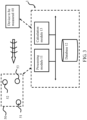
- FIG. 1 Please first refer to FIG. 1 for a system architecture diagram showing configuration of a power positioning device of the present invention.
- a power positioning device 1 includes a processing module 11, a database 12 and a calculation module 13 electrically connected to each other.
- the power positioning device 1 is used to find a device location of a device to be measured 40 in a space by using a known location device 50 (as shown in FIG. 3 ).
- the power positioning device 1 can also use a test transmitting device 20 and a receiving device 30 to create the required data, but the present invention is not limited thereto.
- all the test transmitting device 20, receiving device 30, the device to be measured 40 and the known location device 50 can send and receive wireless signals.
- the wireless signals can be Bluetooth signals, and the test transmitting device 20, the receiving device 30, the device to be measured 40, and the known location device 50 can be the same or different home appliances, computer equipment or mobile devices, etc., but the present invention is not limited thereto.
- each module in the power positioning device 1 may be configured as a hardware device, software program in combination with hardware device, or firmware in combination with hardware device.
- a computer program product may be stored in a computer readable medium and read and executed to achieve the functions of the present invention, and may also be configured in a cloud environment or a virtual server.
- the present invention is not limited in the manner described above. Additionally, the preferred embodiment of the present invention described here is only illustrative. To avoid redundancy, all the possible combinations of changes are not documented in detail.
- the processing module 11, database 12 or calculation module 13 can be provided on the same device or separately in different devices, or can be provided in any of the test transmitting device 20, the receiving device 30, the device to be measured 40 or the known location device 50, but the present invention is not limited thereto.
- the processing module 11 sets a plurality of transmission powers of the test transmitting device 20, so the test transmitting device 20 can emit a plurality of test signals. Then, the receiving device 30 receives the plurality of test signals at a plurality of corresponding distances from the test transmitting device 20, for example, at a distance of 10 cm, 20 cm, or a distance between 1 m and 6 m, and transmits different test signals with different transmission powers.
- the processing module 11 detects intensities of a plurality of test signals received by the receiving device 30 and records the intensities of the plurality of test signals and the plurality of corresponding distances to the database 12. Finally, the calculation module 13 calculates the signal intensity-distance function and signal intensity-distance standard deviation function from the numerical calculation of database 12, and stores them in the database 12.
- FIG. 2 a flowchart showing steps of a data setting process in the present invention. It should be noted here that although the following uses the above power positioning device 1 as an example to illustrate the data setting process of the present invention, the data setting process of the present invention is limited to the power positioning device 1 according to claim 5.
- Step 201 Setting a plurality of transmission powers of a test transmitting device, and causing the test transmitting device to transmit a plurality of test signals to a receiving device under a plurality of corresponding distances.
- the processing module 11 sets a plurality of transmission powers of the test transmitting device 20. Therefore, the test transmitting device 20 can emit a plurality of test signals. Then, the receiving device 30 is allowed to receive the plurality of test signals at a plurality of corresponding distances from the test transmitting device 20, for example, at a distance of 10 cm, 20 cm, or a different distance between 1 m and 6 m.
- Step 202 Detecting intensities of the plurality of test signals received by the receiving device.
- the processing module 11 detects signal intensities of all signals received by the receiving device 30.
- Step 203 Recording intensities of the plurality of test signals and the plurality of corresponding distances to the database.
- the processing module 11 stores the signal intensities of all test signals received by the receiving device 30 and the corresponding distances of the test signals into the database 12.
- Step 204 Calculating and storing a signal intensity-distance function and a signal intensity-distance standard deviation function to the database.
- FIG. 3 a system architecture diagram of a power positioning device performing positioning of the present invention.
- the power positioning device 1 can use a plurality of known location devices 50 to find out a device location of the device to be measured 40 in a space. It should be noted that although an embodiment of the present invention uses the method of directly performing the data setting process to get the signal intensity-distance function and signal intensity-distance standard deviation function, the present invention does not limit the data setting process to be performed every time to re-establish the signal intensity-distance function and signal intensity-distance standard deviation function in the database 12.
- the signal intensity-distance function and signal intensity-distance standard deviation function can be preset to the device to be measured 40 or the known location device 50.
- the processing module 11 controls the device to be measured 40 to emit a plurality of positioning signals at a plurality of transmission powers, such that the plurality of known location devices 50 receive the plurality of positioning signals, and record the intensities of the plurality of positioning signals, a plurality of corresponding receiving time and the locations of the plurality of known location devices 50 to the database 12.
- the plurality of known location devices 50 also receive an identification code of the device to be measured 40, thereby identifying the device to be measured 40. This identification code will also be stored in the database 12.
- the processing module 11 finds out a plurality of devices with the larger signal intensity in the received plurality of positioning signals, such as the known location devices 51, 52, 53.
- the calculation module 13 can find out the device location of device to be measured 40 according to the signal intensity-distance function and the signal intensity-distance standard deviation function from the locations of the known location devices 51, 52, 53.
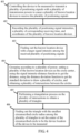
- Step 401 Controlling the device to be measured to transmit a plurality of positioning signals with a plurality of transmission powers to cause a plurality of known location devices to receive the plurality of positioning signals.
- the processing module 11 first controls the device to be measured 40 to transmit positioning signals with different transmission powers.
- the different known location device 50 can receive the positioning signal of the device to be measured 40.
- the plurality of known location devices 50 also receive an identification code of the device to be measured 40.
- Step 402 Recording the plurality of positioning signal intensities, a plurality of corresponding receiving time, and coordinates of the plurality of known location devices.
- the known location device 50 Since the device to be measured 40 transmits positioning signals with different transmission powers, after the known location device 50 receives the positioning signal, the known location device 50 sends all the positioning signals, the corresponding receiving time and coordinates of the known location device 50 back to the database 12.
- Step 403 Finding out the known location device with a larger signal intensity among the received plurality of positioning signals.
- the processing module 11 finds out the known location devices 51, 52, 53 in a plurality of positioning signals that have received a larger signal intensity.
- Step 404 Grouping according to a plurality of power, setting a plurality of the known location devices as the circle center , using the signal intensity-distance function to get the distance, using the distance deviation function to get the standard deviation to draw a plurality of circles, and obtaining a plurality of intersections between the circles.
- the calculation module 13 queries the signal intensity-distance function and the signal intensity-distance standard deviation function according to the plurality of positioning signal intensities, the plurality of corresponding receiving times and the known location devices with the larger intensity.
- the known location devices 51, 52, 53 at different powers are grouped, the fixed point coordinates of the known location devices 51, 52, 53 are taken as the center of the circle, and the distance under this signal intensity according to the signal intensity-distance function can be obtained, that is, the distance is set as the base radius.
- the signal intensity-distance standard deviation function is used to find out the distance standard deviation under the signal intensity, that is, the standard deviation is set as the basis for radius adjustment.
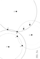
- FIGs. 5A-5B are base to FIG. 4 , to illustrate schematic diagrams of the concentric circles of the power positioning method under different transmission powers of the present invention.
- FIG. 5B is a schematic diagram of the intersection calculated by known location devices 51, 52, 53 at another power. Accordingly, in FIG. 5B , six intersections g-l of known location device 51, 52, 53 at another power can be obtained.
- Step 405 Performing a triangulation process on the plurality of intersections to obtain a plurality of triangles.
- FIG. 5C is base to FIG. 4 , to illustrate a schematic diagram of the triangulation process for the intersection of the power positioning method of the present invention.
- Step 406 Finding out the triangle with the smallest circumscribed circle radius among the plurality of triangles to set the center of the circumscribed circle to be the device location of the device to be measured.
- FIG. 5D is base to FIG. 4 , to illustrate a schematic diagram of finding the smallest concentric circle according to the power positioning method of the present invention.
- the calculation module 13 finds out the center of the smallest circumscribed circle in the triangle with the smallest circumscribed circle radius.
- the coordinate of the device to be measured 40 can be obtained by setting the center of the smallest circumscribed circle to be the device location 41 of the device to be measured 40. Taking FIG. 5D as an example, it can be obtained that the triangle formed by intersection i, h, k is the triangle with the smallest circumscribed circle radius. Therefore, the coordinate of the center of the circumscribed circle is the device location 41.
- the power positioning method of the present invention is not limited to the above order of steps. As long as the objective of the present invention can be achieved, the order of the above steps can also be changed.
- the position of device to be measured 40 can be effectively found without too many additional sensing modules.
Landscapes
- Physics & Mathematics (AREA)
- Engineering & Computer Science (AREA)
- General Physics & Mathematics (AREA)
- Radar, Positioning & Navigation (AREA)
- Remote Sensing (AREA)
- Probability & Statistics with Applications (AREA)
- Position Fixing By Use Of Radio Waves (AREA)
Description
- The present invention relates to a power positioning method and a power positioning device, particularly to a power positioning method and a power positioning device thereof using positioning signals of different transmission powers for positioning.
-
US 2019/331760 A1 discloses a power positioning method, used for a power positioning device to find out a device location of a device to be measured in a space, the space comprising a plurality of known location, the method comprising the following steps: controlling the device to be measured to transmit a plurality of positioning signals by a plurality of transmission powers; causing the plurality of known location devices to receive the plurality of positioning signals, and recording a plurality of positioning signal intensities, a plurality of corresponding beacon types and IDs of the plurality of known location devices to a database; finding out the known location device with a larger signal intensity among the received plurality of positioning signals; taking out a signal intensity-distance function from the database, wherein the distances correspond to the RSSIs; finding out the plurality of known location devices with the larger signal intensity among different powers; and grouping the plurality of known location devices according to a plurality of power to find out the device location of the device to be measured.
Further power positioning methods and devices are known fromUS 2018/213356 A1 ,EP 2 469 298 A1 ,JP 2010 239331 A US 2004/203904 A1 .
Conventionally, the positioning method for indoor devices often involved trilateral positioning. The distance required for trilateral positioning is usually calculated using signal intensity or time of arrival (ToA). Therefore, the signal intensity or the accuracy of ToA calculation may affect the inferred distance, and then the accuracy of the trilateral positioning. With a positioning method relying on transmitting signals at the fixed power, the positioning accuracy is limited by the decline of a single power signal. - Today's mobile devices, like mobile phones, are often equipped with other sensors with different functions. Sensors such as gyroscopes and electronic compasses can assist and improve positioning accuracy. However, in consideration of the device cost, the indoor positioning device may not be equipped with a variety of sensors. Without the assistance of other sensors, indoor positioning can only rely on a signal intensity to estimate a distance and use this data for positioning. However, in the prior art, the signal intensity of Bluetooth devices often varies greatly, resulting in large positioning errors.
- Accordingly, it is necessary to provide a new power positioning method and a power positioning device to solve the problem in the prior art.
- It is a major objective of the present invention to provide an improved power positioning method that can achieve using different power signals for positioning.
- It is another objective of the present invention to provide a power positioning device used for the above method.
- To achieve the above objectives, a power positioning method according to independent claim 1and a power positioning device according to independent claim 5 are provided. The dependent claims show further embodiments of the said method and device, respectively.
- -
-
-
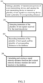
FIG. 1 is a system architecture diagram showing configuration of a power positioning device of the present invention; -
FIG. 2 is a flowchart showing steps of a data setting process of the present invention; -
FIG. 3 is a system architecture diagram showing the power positioning device being positioned of the present invention; -
FIG.4 illustrates a flowchart of the power positioning method of the present invention; -
FIGs.5A-5B illustrate schematic diagrams of the concentric circles of the power positioning method under different transmission powers of the present invention; -
FIG. 5C illustrates a schematic diagram of the triangulation process for the intersection of the power positioning method of the present invention; and -
FIG. 5D illustrates a schematic diagram of finding the smallest concentric circle according to the power positioning method of the present invention. - Hereafter, the technical content of the present invention will be better understood with reference to preferred embodiments. Embodiments which do not comprise all features of the independent claims are included for highlighting specific aspects of the invention.
- Please first refer to
FIG. 1 for a system architecture diagram showing configuration of a power positioning device of the present invention. - In an embodiment, a
power positioning device 1 includes aprocessing module 11, adatabase 12 and acalculation module 13 electrically connected to each other. Thepower positioning device 1 is used to find a device location of a device to be measured 40 in a space by using a known location device 50 (as shown inFIG. 3 ). Before finding out the device to be measured 40, thepower positioning device 1 can also use atest transmitting device 20 and a receivingdevice 30 to create the required data, but the present invention is not limited thereto. Specifically, all thetest transmitting device 20, receivingdevice 30, the device to be measured 40 and the knownlocation device 50 can send and receive wireless signals. The wireless signals can be Bluetooth signals, and thetest transmitting device 20, thereceiving device 30, the device to be measured 40, and the knownlocation device 50 can be the same or different home appliances, computer equipment or mobile devices, etc., but the present invention is not limited thereto. - It should be noted that each module in the
power positioning device 1 may be configured as a hardware device, software program in combination with hardware device, or firmware in combination with hardware device. For example, a computer program product may be stored in a computer readable medium and read and executed to achieve the functions of the present invention, and may also be configured in a cloud environment or a virtual server. However, the present invention is not limited in the manner described above. Additionally, the preferred embodiment of the present invention described here is only illustrative. To avoid redundancy, all the possible combinations of changes are not documented in detail. Theprocessing module 11,database 12 orcalculation module 13 can be provided on the same device or separately in different devices, or can be provided in any of thetest transmitting device 20, thereceiving device 30, the device to be measured 40 or the knownlocation device 50, but the present invention is not limited thereto. - Accordingly, in an embodiment of the present invention, the
processing module 11 sets a plurality of transmission powers of thetest transmitting device 20, so thetest transmitting device 20 can emit a plurality of test signals. Then, thereceiving device 30 receives the plurality of test signals at a plurality of corresponding distances from thetest transmitting device 20, for example, at a distance of 10 cm, 20 cm, or a distance between 1 m and 6 m, and transmits different test signals with different transmission powers. However, the present invention is not limited to the above values. Accordingly, theprocessing module 11 detects intensities of a plurality of test signals received by thereceiving device 30 and records the intensities of the plurality of test signals and the plurality of corresponding distances to thedatabase 12. Finally, thecalculation module 13 calculates the signal intensity-distance function and signal intensity-distance standard deviation function from the numerical calculation ofdatabase 12, and stores them in thedatabase 12. - Then, please refer to
FIG. 2 for a flowchart showing steps of a data setting process in the present invention. It should be noted here that although the following uses the abovepower positioning device 1 as an example to illustrate the data setting process of the present invention, the data setting process of the present invention is limited to thepower positioning device 1 according to claim 5. - First of all, in Step 201: Setting a plurality of transmission powers of a test transmitting device, and causing the test transmitting device to transmit a plurality of test signals to a receiving device under a plurality of corresponding distances.
- First, the
processing module 11 sets a plurality of transmission powers of thetest transmitting device 20. Therefore, thetest transmitting device 20 can emit a plurality of test signals. Then, thereceiving device 30 is allowed to receive the plurality of test signals at a plurality of corresponding distances from thetest transmitting device 20, for example, at a distance of 10 cm, 20 cm, or a different distance between 1 m and 6 m. - Next, in Step 202: Detecting intensities of the plurality of test signals received by the receiving device.
- The
processing module 11 detects signal intensities of all signals received by thereceiving device 30. - Then, in Step 203: Recording intensities of the plurality of test signals and the plurality of corresponding distances to the database.
- The
processing module 11 stores the signal intensities of all test signals received by thereceiving device 30 and the corresponding distances of the test signals into thedatabase 12. - Finally, in Step 204: Calculating and storing a signal intensity-distance function and a signal intensity-distance standard deviation function to the database.
- Finally, according to the signal intensities of all the signals and the corresponding distances of the signals, the
calculation module 13 can calculate the signal intensity-distance function and signal intensity-distance standard deviation function for each different transmission power to know the relationship between the signal intensity received by thereceiving device 30 and thetest transmitting device 20 and the standard deviation. Then, thecalculation module 13 can store the functions in thedatabase 12. In this way, the data setting process of the present invention can be completed. - Hereafter, please refer to
FIG. 3 for a system architecture diagram of a power positioning device performing positioning of the present invention. - After the signal intensity-distance function and signal intensity-distance standard deviation function are established in the
database 12, thepower positioning device 1 can use a plurality of knownlocation devices 50 to find out a device location of the device to be measured 40 in a space. It should be noted that although an embodiment of the present invention uses the method of directly performing the data setting process to get the signal intensity-distance function and signal intensity-distance standard deviation function, the present invention does not limit the data setting process to be performed every time to re-establish the signal intensity-distance function and signal intensity-distance standard deviation function in thedatabase 12. The signal intensity-distance function and signal intensity-distance standard deviation function can be preset to the device to be measured 40 or the knownlocation device 50. - Accordingly, the
processing module 11 controls the device to be measured 40 to emit a plurality of positioning signals at a plurality of transmission powers, such that the plurality of knownlocation devices 50 receive the plurality of positioning signals, and record the intensities of the plurality of positioning signals, a plurality of corresponding receiving time and the locations of the plurality of knownlocation devices 50 to thedatabase 12. The plurality of knownlocation devices 50 also receive an identification code of the device to be measured 40, thereby identifying the device to be measured 40. This identification code will also be stored in thedatabase 12. As such, theprocessing module 11 finds out a plurality of devices with the larger signal intensity in the received plurality of positioning signals, such as the knownlocation devices calculation module 13 can find out the device location of device to be measured 40 according to the signal intensity-distance function and the signal intensity-distance standard deviation function from the locations of the knownlocation devices - For the detailed method of finding out the device location of device to be measured 40, please refer to
Figure 4 related to a flowchart showing steps of a device positioning process of the present invention. - First of all, in Step 401: Controlling the device to be measured to transmit a plurality of positioning signals with a plurality of transmission powers to cause a plurality of known location devices to receive the plurality of positioning signals.
- First, when the device to be measured 40 enters a space, the
processing module 11 first controls the device to be measured 40 to transmit positioning signals with different transmission powers. In this way, the different knownlocation device 50 can receive the positioning signal of the device to be measured 40. The plurality of knownlocation devices 50 also receive an identification code of the device to be measured 40. - Next, in Step 402: Recording the plurality of positioning signal intensities, a plurality of corresponding receiving time, and coordinates of the plurality of known location devices.
- Since the device to be measured 40 transmits positioning signals with different transmission powers, after the known
location device 50 receives the positioning signal, the knownlocation device 50 sends all the positioning signals, the corresponding receiving time and coordinates of the knownlocation device 50 back to thedatabase 12. - Further, in Step 403: Finding out the known location device with a larger signal intensity among the received plurality of positioning signals.
- From the data of
database 12, theprocessing module 11 finds out the knownlocation devices - Then, in Step 404: Grouping according to a plurality of power, setting a plurality of the known location devices as the circle center , using the signal intensity-distance function to get the distance, using the distance deviation function to get the standard deviation to draw a plurality of circles, and obtaining a plurality of intersections between the circles.
- Next, the
calculation module 13 queries the signal intensity-distance function and the signal intensity-distance standard deviation function according to the plurality of positioning signal intensities, the plurality of corresponding receiving times and the known location devices with the larger intensity. The knownlocation devices location devices - Hereafter, please refer to
FIGs. 5A-5B are base toFIG. 4 , to illustrate schematic diagrams of the concentric circles of the power positioning method under different transmission powers of the present invention. - Therefore, in the present embodiment, a plurality of circles with the fixed point coordinates of the known
location devices FIG. 5A , the original radius distance minus 0.67 standard deviation is set as the minimum radius, and the original radius distance plus 0.67 standard deviation is set as the maximum radius. If the two circles are tangent or intersect, it can be ended. As such, a plurality of intersections a-f among a plurality of circles can be obtained, that is, the circle of the knownlocation devices location device location devices location devices FIG. 5B is a schematic diagram of the intersection calculated by knownlocation devices FIG. 5B , six intersections g-l of knownlocation device - Next, in Step 405: Performing a triangulation process on the plurality of intersections to obtain a plurality of triangles.
- Hereafter, please refer to
FIG. 5C is base toFIG. 4 , to illustrate a schematic diagram of the triangulation process for the intersection of the power positioning method of the present invention. - At this time, the
calculation module 13 removes outliers of all the intersections a-l and performs a Drouin triangulation process to obtain a plurality of triangles. In this embodiment, 12 intersections a-l obtained from two different powers are used for calculation, but the present invention is not limited thereto. More intersections can get more accurate results. - Finally, in Step 406: Finding out the triangle with the smallest circumscribed circle radius among the plurality of triangles to set the center of the circumscribed circle to be the device location of the device to be measured.
- Hereafter, please refer to
FIG. 5D is base toFIG. 4 , to illustrate a schematic diagram of finding the smallest concentric circle according to the power positioning method of the present invention. - Finally, the
calculation module 13 finds out the center of the smallest circumscribed circle in the triangle with the smallest circumscribed circle radius. The coordinate of the device to be measured 40 can be obtained by setting the center of the smallest circumscribed circle to be thedevice location 41 of the device to be measured 40. TakingFIG. 5D as an example, it can be obtained that the triangle formed by intersection i, h, k is the triangle with the smallest circumscribed circle radius. Therefore, the coordinate of the center of the circumscribed circle is thedevice location 41. - It should be noted here that the power positioning method of the present invention is not limited to the above order of steps. As long as the objective of the present invention can be achieved, the order of the above steps can also be changed.
- With the power positioning method and
power positioning device 1, the position of device to be measured 40 can be effectively found without too many additional sensing modules. - It should be noted that the embodiments of the present invention described above are only illustrative. The invention is defined solely by the appended claims.
Claims (8)
- A power positioning method, used in a power positioning device (1) to find a device location (41) of a device to be measured (40) in a space, the space comprising a plurality of known location devices (50), the method comprising the following steps:controlling the device to be measured (40) to transmit a plurality of positioning signals by a plurality of transmission powers;causing the plurality of known location devices (50) to receive the plurality of positioning signals, and recording a plurality of positioning signal intensities, a plurality of corresponding receiving times and coordinates of the plurality of known location devices (50) to a database (12);finding out a plurality of known location devices (50) with a larger signal intensity among the received plurality of positioning signals;querying a signal intensity-distance function and a signal intensity-distance standard deviation function from the database (12) according to the plurality of positioning signal intensities, the plurality of corresponding receiving times and the known location devices (50) with the larger signal intensity;grouping the plurality of known location devices (50) according to different powers and setting the plurality of the known location devices (50) as circle centers, using the signal intensity-distance function to obtain a distance, and using the standard deviation obtained by the signal intensity-distance standarddeviation function to draw a plurality of circles;obtaining a plurality of intersections (a) between the plurality of circles;performing a triangulation process on the plurality of intersections (a) to obtain a plurality of triangles; andfinding out a triangle with a smallest circumscribed circle radius among the plurality of triangles to set the center of the circumscribed circle to be the device location (41) of the device to be measured (40).
- The power positioning method as claimed in claim 1 , further comprising the step of finding out three known location devices (50) with the larger signal intensity.
- The power positioning method as claimed in claim 1, further comprising the step of receiving an identification code of the device to be measured (40).
- The power positioning method as claimed in claim 1, further comprising a step of performing a data setting process, the data setting process comprising the steps of:setting a plurality of transmission powers of a test transmitting device (20) so that the test transmitting device transmits a plurality of different test signals to a receiving device (30) at a plurality of corresponding distances, wherein the different test signals correspond to different transmission powers;detecting intensities of the plurality of test signals received by the receiving device (30);recording the intensities of the plurality of test signals and the plurality of corresponding distances to the database (12);calculating the signal intensity-distance function and the signal intensity-distance standard deviation function for each transmission power according to the intensities of the plurality of test signals and the plurality of corresponding distances; andstoring the signal intensity-distance function and the signal intensity-distance standard deviation function to the database (12).
- A power positioning device (1), used to find a device location (41) of a device to be measured (40) in a space, wherein the space further comprising a plurality of known location devices (50), the power positioning device (1) comprising:a processing module (11), which controls the device to be measured (40) to transmit a plurality of positioning signals by a plurality of transmission powers, causing the plurality of known location devices (50) to receive the plurality of positioning signals;a database (12), which is electrically connected to the processing module (11) and configured for storing a signal intensity-distance function and a signal intensity-distance standard deviation function, and after the plurality of known location devices (50) receive the plurality of positioning signals, the database (12) records the plurality of positioning signal intensities, a plurality of corresponding receiving times, and coordinates of the plurality of known location devices, such that the (50) processing module (11) finds out a plurality of known location devices (50) with a larger signal intensity among the received plurality of positioning signals; anda calculation module (13), which is electrically connected to the database (12) and configured for querying the signal intensity-distance function and the signal intensity-distance standard deviation function according to the plurality of positioning signal intensities, the plurality of corresponding receiving times and the known location devices (50) with the larger signal intensity, and then the processing module (11) groups the plurality of known location devices (50) according to different powers andte- sets the plurality of the known location devices (50) as circle centers, uses the signal intensity-distance function to obtain a distance, uses the signal intensity-distance standard deviation function to draw a plurality of circles, and obtains a plurality of intersections (a) between the plurality of circles, thereby the calculation module (13) performs a triangulation process on the plurality of intersections (a) to Z obtain a plurality of triangles andfind out a center of a smallest circumscribed circle among the triangles with the smallest circumscribed circle radius, and sets it to be the device location (41) of the device to be measured (40).
- The power positioning device (1) as claimed in claim 5, wherein the processing module (11) finds out three known location devices (50) with the larger signal intensity.
- The power positioning device (1) as claimed in claim 5, comprising receiving an identification code of the device to be measured (40).
- The power positioning device (1) as claimed in claim 5, wherein the processing module (11) sets a plurality of transmission powers of a test transmitting device (20) to transmit a plurality of different test signals, causing a receiving device (30) to receive the plurality of test signals at a plurality of corresponding distances from the test transmitting device (20), wherein the different test signals correspond to different transmission powers; thereby the processing module (11) detects intensities of the plurality of test signals received by the receiving device (30) to record the intensities of the plurality of test signals and the plurality of corresponding distances to the database (12), such that the calculation module (13) calculates the signal intensity-distance function and the signal intensity-distance standard deviation function for each transmission power according to the intensities of the plurality of test signals and the plurality of corresponding distances and stores the signal intensity-distance function and the signal intensity-distance standard deviation function to the database.
Applications Claiming Priority (1)
| Application Number | Priority Date | Filing Date | Title |
|---|---|---|---|
| TW108147431A TWI720758B (en) | 2019-12-24 | 2019-12-24 | Power positioning method and power positioning device thereof |
Publications (2)
| Publication Number | Publication Date |
|---|---|
| EP3842820A1 EP3842820A1 (en) | 2021-06-30 |
| EP3842820B1 true EP3842820B1 (en) | 2024-07-03 |
Family
ID=73039856
Family Applications (1)
| Application Number | Title | Priority Date | Filing Date |
|---|---|---|---|
| EP20204630.6A Active EP3842820B1 (en) | 2019-12-24 | 2020-10-29 | Power positioning method and power positioning device |
Country Status (3)
| Country | Link |
|---|---|
| EP (1) | EP3842820B1 (en) |
| JP (1) | JP2021103159A (en) |
| TW (1) | TWI720758B (en) |
Families Citing this family (7)
| Publication number | Priority date | Publication date | Assignee | Title |
|---|---|---|---|---|
| JP7670558B2 (en) * | 2021-06-22 | 2025-04-30 | 株式会社三共 | Gaming Machines |
| JP7763607B2 (en) * | 2021-06-22 | 2025-11-04 | 株式会社三共 | gaming machines |
| JP7597673B2 (en) * | 2021-07-21 | 2024-12-10 | 株式会社三共 | Gaming Machines |
| JP7597672B2 (en) * | 2021-07-21 | 2024-12-10 | 株式会社三共 | Gaming Machines |
| JP7597669B2 (en) * | 2021-07-21 | 2024-12-10 | 株式会社三共 | Gaming Machines |
| JP7597668B2 (en) * | 2021-07-21 | 2024-12-10 | 株式会社三共 | Gaming Machines |
| CN114119459B (en) * | 2021-09-15 | 2025-06-03 | 苏州超集信息科技有限公司 | A method and system for locating power port of electrical product insulation test |
Family Cites Families (8)
| Publication number | Priority date | Publication date | Assignee | Title |
|---|---|---|---|---|
| US7257411B2 (en) * | 2002-12-27 | 2007-08-14 | Ntt Docomo, Inc. | Selective fusion location estimation (SELFLOC) for wireless access technologies |
| JP5240691B2 (en) * | 2009-03-31 | 2013-07-17 | 株式会社国際電気通信基礎技術研究所 | Owner identification system |
| EP2469298B1 (en) * | 2010-12-23 | 2015-02-18 | Televic Healthcare NV | Method and device for determining location of a target |
| TW201329485A (en) * | 2012-01-06 | 2013-07-16 | Novatek Microelectronics Corp | Wireless communication positioning method |
| CN108780538A (en) * | 2016-03-23 | 2018-11-09 | 联邦快递服务公司 | Systems, devices and methods for self-adjusting broadcast settings of nodes in a network of wireless nodes |
| US10129700B2 (en) * | 2016-11-14 | 2018-11-13 | WiSilica Inc. | Prediction algorithm for location estimation |
| JP6597918B2 (en) * | 2017-01-20 | 2019-10-30 | 株式会社村田製作所 | Position detection system |
| TWI675215B (en) * | 2018-08-16 | 2019-10-21 | 恆準定位股份有限公司 | Indoor positioning system |
-
2019
- 2019-12-24 TW TW108147431A patent/TWI720758B/en not_active IP Right Cessation
-
2020
- 2020-08-14 JP JP2020136939A patent/JP2021103159A/en active Pending
- 2020-10-29 EP EP20204630.6A patent/EP3842820B1/en active Active
Also Published As
| Publication number | Publication date |
|---|---|
| TWI720758B (en) | 2021-03-01 |
| TW202124993A (en) | 2021-07-01 |
| EP3842820A1 (en) | 2021-06-30 |
| JP2021103159A (en) | 2021-07-15 |
Similar Documents
| Publication | Publication Date | Title |
|---|---|---|
| EP3842820A1 (en) | Power positioning method and power positioning device | |
| CN103560813B (en) | Mobile terminal positioning method and device based on Bluetooth technology | |
| CN111829525A (en) | UWB indoor and outdoor integrated intelligent navigation and positioning method and system | |
| CN108917762B (en) | Method and system for positioning electric appliance, storage medium and home system | |
| EP3835808B1 (en) | Dynamic power positioning method and dynamic power positioning system | |
| WO2019052575A1 (en) | Method, apparatus and device for positioning wireless device, and storage medium | |
| US11265677B2 (en) | Power positioning method and power positioning device thereof | |
| CN114543804B (en) | Two-way signal positioning method and two-way signal positioning system | |
| US20240142563A1 (en) | Method and system for wireless positioning | |
| US11454695B2 (en) | Dynamic power positioning method and dynamic power positioning system thereof | |
| CN113050033B (en) | Power positioning method and power positioning device | |
| US20230288526A1 (en) | Beacon map construction method, device, and computer-readable storage medium | |
| CN113009415B (en) | Dynamic power positioning method and dynamic power positioning system thereof | |
| CN110824461B (en) | Positioning method | |
| CN202694354U (en) | Precise personnel positioning system based on TOA (Time of Arrival) ranging | |
| CN206710590U (en) | A kind of indoor service robot positioning system based on iBeacon | |
| CN114487997A (en) | Relative position positioning system and relative position positioning method thereof | |
| CN110809239A (en) | Pipe gallery personnel positioning method, server and system | |
| CN111545375B (en) | Positioning spraying method, device and system and storage medium | |
| CN112304335B (en) | Hydraulic support tilt sensor calibration method and system | |
| CN115683022B (en) | Wheel spacing and wheel diameter calibration method and device for double-wheel differential mobile robot | |
| CN112699700A (en) | Intelligent robot positioning system and method based on radio frequency technology | |
| CN114245307A (en) | Positioning method and device for robot, electronic equipment and storage medium | |
| US11485024B2 (en) | Determination of object position by aligned device placement | |
| CN115717857A (en) | Device and method for detecting relative position of object |
Legal Events
| Date | Code | Title | Description |
|---|---|---|---|
| PUAI | Public reference made under article 153(3) epc to a published international application that has entered the european phase |
Free format text: ORIGINAL CODE: 0009012 |
|
| STAA | Information on the status of an ep patent application or granted ep patent |
Free format text: STATUS: THE APPLICATION HAS BEEN PUBLISHED |
|
| AK | Designated contracting states |
Kind code of ref document: A1 Designated state(s): AL AT BE BG CH CY CZ DE DK EE ES FI FR GB GR HR HU IE IS IT LI LT LU LV MC MK MT NL NO PL PT RO RS SE SI SK SM TR |
|
| STAA | Information on the status of an ep patent application or granted ep patent |
Free format text: STATUS: REQUEST FOR EXAMINATION WAS MADE |
|
| 17P | Request for examination filed |
Effective date: 20211230 |
|
| RBV | Designated contracting states (corrected) |
Designated state(s): AL AT BE BG CH CY CZ DE DK EE ES FI FR GB GR HR HU IE IS IT LI LT LU LV MC MK MT NL NO PL PT RO RS SE SI SK SM TR |
|
| GRAP | Despatch of communication of intention to grant a patent |
Free format text: ORIGINAL CODE: EPIDOSNIGR1 |
|
| STAA | Information on the status of an ep patent application or granted ep patent |
Free format text: STATUS: GRANT OF PATENT IS INTENDED |
|
| INTG | Intention to grant announced |
Effective date: 20240226 |
|
| GRAS | Grant fee paid |
Free format text: ORIGINAL CODE: EPIDOSNIGR3 |
|
| GRAA | (expected) grant |
Free format text: ORIGINAL CODE: 0009210 |
|
| STAA | Information on the status of an ep patent application or granted ep patent |
Free format text: STATUS: THE PATENT HAS BEEN GRANTED |
|
| AK | Designated contracting states |
Kind code of ref document: B1 Designated state(s): AL AT BE BG CH CY CZ DE DK EE ES FI FR GB GR HR HU IE IS IT LI LT LU LV MC MK MT NL NO PL PT RO RS SE SI SK SM TR |
|
| REG | Reference to a national code |
Ref country code: CH Ref legal event code: EP |
|
| REG | Reference to a national code |
Ref country code: DE Ref legal event code: R096 Ref document number: 602020033230 Country of ref document: DE |
|
| REG | Reference to a national code |
Ref country code: LT Ref legal event code: MG9D |
|
| REG | Reference to a national code |
Ref country code: NL Ref legal event code: MP Effective date: 20240703 |
|
| PG25 | Lapsed in a contracting state [announced via postgrant information from national office to epo] |
Ref country code: PT Free format text: LAPSE BECAUSE OF FAILURE TO SUBMIT A TRANSLATION OF THE DESCRIPTION OR TO PAY THE FEE WITHIN THE PRESCRIBED TIME-LIMIT Effective date: 20241104 |
|
| REG | Reference to a national code |
Ref country code: AT Ref legal event code: MK05 Ref document number: 1700375 Country of ref document: AT Kind code of ref document: T Effective date: 20240703 |
|
| PG25 | Lapsed in a contracting state [announced via postgrant information from national office to epo] |
Ref country code: NL Free format text: LAPSE BECAUSE OF FAILURE TO SUBMIT A TRANSLATION OF THE DESCRIPTION OR TO PAY THE FEE WITHIN THE PRESCRIBED TIME-LIMIT Effective date: 20240703 |
|
| PG25 | Lapsed in a contracting state [announced via postgrant information from national office to epo] |
Ref country code: PT Free format text: LAPSE BECAUSE OF FAILURE TO SUBMIT A TRANSLATION OF THE DESCRIPTION OR TO PAY THE FEE WITHIN THE PRESCRIBED TIME-LIMIT Effective date: 20241104 Ref country code: NL Free format text: LAPSE BECAUSE OF FAILURE TO SUBMIT A TRANSLATION OF THE DESCRIPTION OR TO PAY THE FEE WITHIN THE PRESCRIBED TIME-LIMIT Effective date: 20240703 |
|
| PGFP | Annual fee paid to national office [announced via postgrant information from national office to epo] |
Ref country code: DE Payment date: 20241025 Year of fee payment: 5 |
|
| PG25 | Lapsed in a contracting state [announced via postgrant information from national office to epo] |
Ref country code: NO Free format text: LAPSE BECAUSE OF FAILURE TO SUBMIT A TRANSLATION OF THE DESCRIPTION OR TO PAY THE FEE WITHIN THE PRESCRIBED TIME-LIMIT Effective date: 20241003 |
|
| PG25 | Lapsed in a contracting state [announced via postgrant information from national office to epo] |
Ref country code: FI Free format text: LAPSE BECAUSE OF FAILURE TO SUBMIT A TRANSLATION OF THE DESCRIPTION OR TO PAY THE FEE WITHIN THE PRESCRIBED TIME-LIMIT Effective date: 20240703 Ref country code: GR Free format text: LAPSE BECAUSE OF FAILURE TO SUBMIT A TRANSLATION OF THE DESCRIPTION OR TO PAY THE FEE WITHIN THE PRESCRIBED TIME-LIMIT Effective date: 20241004 Ref country code: PL Free format text: LAPSE BECAUSE OF FAILURE TO SUBMIT A TRANSLATION OF THE DESCRIPTION OR TO PAY THE FEE WITHIN THE PRESCRIBED TIME-LIMIT Effective date: 20240703 |
|
| PGFP | Annual fee paid to national office [announced via postgrant information from national office to epo] |
Ref country code: GB Payment date: 20241024 Year of fee payment: 5 |
|
| PG25 | Lapsed in a contracting state [announced via postgrant information from national office to epo] |
Ref country code: BG Free format text: LAPSE BECAUSE OF FAILURE TO SUBMIT A TRANSLATION OF THE DESCRIPTION OR TO PAY THE FEE WITHIN THE PRESCRIBED TIME-LIMIT Effective date: 20240703 |
|
| PG25 | Lapsed in a contracting state [announced via postgrant information from national office to epo] |
Ref country code: LV Free format text: LAPSE BECAUSE OF FAILURE TO SUBMIT A TRANSLATION OF THE DESCRIPTION OR TO PAY THE FEE WITHIN THE PRESCRIBED TIME-LIMIT Effective date: 20240703 |
|
| PG25 | Lapsed in a contracting state [announced via postgrant information from national office to epo] |
Ref country code: AT Free format text: LAPSE BECAUSE OF FAILURE TO SUBMIT A TRANSLATION OF THE DESCRIPTION OR TO PAY THE FEE WITHIN THE PRESCRIBED TIME-LIMIT Effective date: 20240703 Ref country code: IS Free format text: LAPSE BECAUSE OF FAILURE TO SUBMIT A TRANSLATION OF THE DESCRIPTION OR TO PAY THE FEE WITHIN THE PRESCRIBED TIME-LIMIT Effective date: 20241103 |
|
| PGFP | Annual fee paid to national office [announced via postgrant information from national office to epo] |
Ref country code: FR Payment date: 20241025 Year of fee payment: 5 |
|
| PG25 | Lapsed in a contracting state [announced via postgrant information from national office to epo] |
Ref country code: HR Free format text: LAPSE BECAUSE OF FAILURE TO SUBMIT A TRANSLATION OF THE DESCRIPTION OR TO PAY THE FEE WITHIN THE PRESCRIBED TIME-LIMIT Effective date: 20240703 Ref country code: CZ Free format text: LAPSE BECAUSE OF FAILURE TO SUBMIT A TRANSLATION OF THE DESCRIPTION OR TO PAY THE FEE WITHIN THE PRESCRIBED TIME-LIMIT Effective date: 20240703 |
|
| PG25 | Lapsed in a contracting state [announced via postgrant information from national office to epo] |
Ref country code: ES Free format text: LAPSE BECAUSE OF FAILURE TO SUBMIT A TRANSLATION OF THE DESCRIPTION OR TO PAY THE FEE WITHIN THE PRESCRIBED TIME-LIMIT Effective date: 20240703 Ref country code: RS Free format text: LAPSE BECAUSE OF FAILURE TO SUBMIT A TRANSLATION OF THE DESCRIPTION OR TO PAY THE FEE WITHIN THE PRESCRIBED TIME-LIMIT Effective date: 20241003 |
|
| PG25 | Lapsed in a contracting state [announced via postgrant information from national office to epo] |
Ref country code: RS Free format text: LAPSE BECAUSE OF FAILURE TO SUBMIT A TRANSLATION OF THE DESCRIPTION OR TO PAY THE FEE WITHIN THE PRESCRIBED TIME-LIMIT Effective date: 20241003 Ref country code: PL Free format text: LAPSE BECAUSE OF FAILURE TO SUBMIT A TRANSLATION OF THE DESCRIPTION OR TO PAY THE FEE WITHIN THE PRESCRIBED TIME-LIMIT Effective date: 20240703 Ref country code: NO Free format text: LAPSE BECAUSE OF FAILURE TO SUBMIT A TRANSLATION OF THE DESCRIPTION OR TO PAY THE FEE WITHIN THE PRESCRIBED TIME-LIMIT Effective date: 20241003 Ref country code: LV Free format text: LAPSE BECAUSE OF FAILURE TO SUBMIT A TRANSLATION OF THE DESCRIPTION OR TO PAY THE FEE WITHIN THE PRESCRIBED TIME-LIMIT Effective date: 20240703 Ref country code: IS Free format text: LAPSE BECAUSE OF FAILURE TO SUBMIT A TRANSLATION OF THE DESCRIPTION OR TO PAY THE FEE WITHIN THE PRESCRIBED TIME-LIMIT Effective date: 20241103 Ref country code: HR Free format text: LAPSE BECAUSE OF FAILURE TO SUBMIT A TRANSLATION OF THE DESCRIPTION OR TO PAY THE FEE WITHIN THE PRESCRIBED TIME-LIMIT Effective date: 20240703 Ref country code: GR Free format text: LAPSE BECAUSE OF FAILURE TO SUBMIT A TRANSLATION OF THE DESCRIPTION OR TO PAY THE FEE WITHIN THE PRESCRIBED TIME-LIMIT Effective date: 20241004 Ref country code: FI Free format text: LAPSE BECAUSE OF FAILURE TO SUBMIT A TRANSLATION OF THE DESCRIPTION OR TO PAY THE FEE WITHIN THE PRESCRIBED TIME-LIMIT Effective date: 20240703 Ref country code: ES Free format text: LAPSE BECAUSE OF FAILURE TO SUBMIT A TRANSLATION OF THE DESCRIPTION OR TO PAY THE FEE WITHIN THE PRESCRIBED TIME-LIMIT Effective date: 20240703 Ref country code: CZ Free format text: LAPSE BECAUSE OF FAILURE TO SUBMIT A TRANSLATION OF THE DESCRIPTION OR TO PAY THE FEE WITHIN THE PRESCRIBED TIME-LIMIT Effective date: 20240703 Ref country code: BG Free format text: LAPSE BECAUSE OF FAILURE TO SUBMIT A TRANSLATION OF THE DESCRIPTION OR TO PAY THE FEE WITHIN THE PRESCRIBED TIME-LIMIT Effective date: 20240703 Ref country code: AT Free format text: LAPSE BECAUSE OF FAILURE TO SUBMIT A TRANSLATION OF THE DESCRIPTION OR TO PAY THE FEE WITHIN THE PRESCRIBED TIME-LIMIT Effective date: 20240703 |
|
| REG | Reference to a national code |
Ref country code: DE Ref legal event code: R097 Ref document number: 602020033230 Country of ref document: DE |
|
| PG25 | Lapsed in a contracting state [announced via postgrant information from national office to epo] |
Ref country code: DK Free format text: LAPSE BECAUSE OF FAILURE TO SUBMIT A TRANSLATION OF THE DESCRIPTION OR TO PAY THE FEE WITHIN THE PRESCRIBED TIME-LIMIT Effective date: 20240703 Ref country code: SM Free format text: LAPSE BECAUSE OF FAILURE TO SUBMIT A TRANSLATION OF THE DESCRIPTION OR TO PAY THE FEE WITHIN THE PRESCRIBED TIME-LIMIT Effective date: 20240703 Ref country code: RO Free format text: LAPSE BECAUSE OF FAILURE TO SUBMIT A TRANSLATION OF THE DESCRIPTION OR TO PAY THE FEE WITHIN THE PRESCRIBED TIME-LIMIT Effective date: 20240703 |
|
| PG25 | Lapsed in a contracting state [announced via postgrant information from national office to epo] |
Ref country code: EE Free format text: LAPSE BECAUSE OF FAILURE TO SUBMIT A TRANSLATION OF THE DESCRIPTION OR TO PAY THE FEE WITHIN THE PRESCRIBED TIME-LIMIT Effective date: 20240703 |
|
| PG25 | Lapsed in a contracting state [announced via postgrant information from national office to epo] |
Ref country code: IT Free format text: LAPSE BECAUSE OF FAILURE TO SUBMIT A TRANSLATION OF THE DESCRIPTION OR TO PAY THE FEE WITHIN THE PRESCRIBED TIME-LIMIT Effective date: 20240703 Ref country code: SK Free format text: LAPSE BECAUSE OF FAILURE TO SUBMIT A TRANSLATION OF THE DESCRIPTION OR TO PAY THE FEE WITHIN THE PRESCRIBED TIME-LIMIT Effective date: 20240703 |
|
| PLBE | No opposition filed within time limit |
Free format text: ORIGINAL CODE: 0009261 |
|
| STAA | Information on the status of an ep patent application or granted ep patent |
Free format text: STATUS: NO OPPOSITION FILED WITHIN TIME LIMIT |
|
| REG | Reference to a national code |
Ref country code: CH Ref legal event code: PL |
|
| 26N | No opposition filed |
Effective date: 20250404 |
|
| PG25 | Lapsed in a contracting state [announced via postgrant information from national office to epo] |
Ref country code: MC Free format text: LAPSE BECAUSE OF FAILURE TO SUBMIT A TRANSLATION OF THE DESCRIPTION OR TO PAY THE FEE WITHIN THE PRESCRIBED TIME-LIMIT Effective date: 20240703 |
|
| PG25 | Lapsed in a contracting state [announced via postgrant information from national office to epo] |
Ref country code: BE Free format text: LAPSE BECAUSE OF NON-PAYMENT OF DUE FEES Effective date: 20241031 Ref country code: LU Free format text: LAPSE BECAUSE OF NON-PAYMENT OF DUE FEES Effective date: 20241029 |
|
| PG25 | Lapsed in a contracting state [announced via postgrant information from national office to epo] |
Ref country code: CH Free format text: LAPSE BECAUSE OF NON-PAYMENT OF DUE FEES Effective date: 20241031 |
|
| REG | Reference to a national code |
Ref country code: BE Ref legal event code: MM Effective date: 20241031 |
|
| PG25 | Lapsed in a contracting state [announced via postgrant information from national office to epo] |
Ref country code: SE Free format text: LAPSE BECAUSE OF FAILURE TO SUBMIT A TRANSLATION OF THE DESCRIPTION OR TO PAY THE FEE WITHIN THE PRESCRIBED TIME-LIMIT Effective date: 20240703 |
|
| PG25 | Lapsed in a contracting state [announced via postgrant information from national office to epo] |
Ref country code: IE Free format text: LAPSE BECAUSE OF NON-PAYMENT OF DUE FEES Effective date: 20241029 |
|
| PG25 | Lapsed in a contracting state [announced via postgrant information from national office to epo] |
Ref country code: HU Free format text: LAPSE BECAUSE OF FAILURE TO SUBMIT A TRANSLATION OF THE DESCRIPTION OR TO PAY THE FEE WITHIN THE PRESCRIBED TIME-LIMIT; INVALID AB INITIO Effective date: 20201029 |
|
| PG25 | Lapsed in a contracting state [announced via postgrant information from national office to epo] |
Ref country code: CY Free format text: LAPSE BECAUSE OF FAILURE TO SUBMIT A TRANSLATION OF THE DESCRIPTION OR TO PAY THE FEE WITHIN THE PRESCRIBED TIME-LIMIT; INVALID AB INITIO Effective date: 20201029 |