EP3842794A1 - Sensor system comprising low-power memory - Google Patents
Sensor system comprising low-power memory Download PDFInfo
- Publication number
- EP3842794A1 EP3842794A1 EP20212022.6A EP20212022A EP3842794A1 EP 3842794 A1 EP3842794 A1 EP 3842794A1 EP 20212022 A EP20212022 A EP 20212022A EP 3842794 A1 EP3842794 A1 EP 3842794A1
- Authority
- EP
- European Patent Office
- Prior art keywords
- wire
- parameter
- electrode
- counter
- sensor system
- Prior art date
- Legal status (The legal status is an assumption and is not a legal conclusion. Google has not performed a legal analysis and makes no representation as to the accuracy of the status listed.)
- Withdrawn
Links
Images


Classifications
-
- G—PHYSICS
- G01—MEASURING; TESTING
- G01N—INVESTIGATING OR ANALYSING MATERIALS BY DETERMINING THEIR CHEMICAL OR PHYSICAL PROPERTIES
- G01N27/00—Investigating or analysing materials by the use of electric, electrochemical, or magnetic means
- G01N27/26—Investigating or analysing materials by the use of electric, electrochemical, or magnetic means by investigating electrochemical variables; by using electrolysis or electrophoresis
- G01N27/403—Cells and electrode assemblies
-
- G—PHYSICS
- G01—MEASURING; TESTING
- G01D—MEASURING NOT SPECIALLY ADAPTED FOR A SPECIFIC VARIABLE; ARRANGEMENTS FOR MEASURING TWO OR MORE VARIABLES NOT COVERED IN A SINGLE OTHER SUBCLASS; TARIFF METERING APPARATUS; MEASURING OR TESTING NOT OTHERWISE PROVIDED FOR
- G01D9/00—Recording measured values
- G01D9/02—Producing one or more recordings of the values of a single variable
-
- G—PHYSICS
- G01—MEASURING; TESTING
- G01N—INVESTIGATING OR ANALYSING MATERIALS BY DETERMINING THEIR CHEMICAL OR PHYSICAL PROPERTIES
- G01N27/00—Investigating or analysing materials by the use of electric, electrochemical, or magnetic means
- G01N27/26—Investigating or analysing materials by the use of electric, electrochemical, or magnetic means by investigating electrochemical variables; by using electrolysis or electrophoresis
- G01N27/416—Systems
-
- G—PHYSICS
- G11—INFORMATION STORAGE
- G11C—STATIC STORES
- G11C13/00—Digital stores characterised by the use of storage elements not covered by groups G11C11/00, G11C23/00, or G11C25/00
- G11C13/0002—Digital stores characterised by the use of storage elements not covered by groups G11C11/00, G11C23/00, or G11C25/00 using resistive RAM [RRAM] elements
- G11C13/0009—RRAM elements whose operation depends upon chemical change
-
- G—PHYSICS
- G11—INFORMATION STORAGE
- G11C—STATIC STORES
- G11C13/00—Digital stores characterised by the use of storage elements not covered by groups G11C11/00, G11C23/00, or G11C25/00
- G11C13/02—Digital stores characterised by the use of storage elements not covered by groups G11C11/00, G11C23/00, or G11C25/00 using elements whose operation depends upon chemical change
-
- H—ELECTRICITY
- H01—ELECTRIC ELEMENTS
- H01B—CABLES; CONDUCTORS; INSULATORS; SELECTION OF MATERIALS FOR THEIR CONDUCTIVE, INSULATING OR DIELECTRIC PROPERTIES
- H01B1/00—Conductors or conductive bodies characterised by the conductive materials; Selection of materials as conductors
- H01B1/02—Conductors or conductive bodies characterised by the conductive materials; Selection of materials as conductors mainly consisting of metals or alloys
-
- H—ELECTRICITY
- H01—ELECTRIC ELEMENTS
- H01B—CABLES; CONDUCTORS; INSULATORS; SELECTION OF MATERIALS FOR THEIR CONDUCTIVE, INSULATING OR DIELECTRIC PROPERTIES
- H01B1/00—Conductors or conductive bodies characterised by the conductive materials; Selection of materials as conductors
- H01B1/06—Conductors or conductive bodies characterised by the conductive materials; Selection of materials as conductors mainly consisting of other non-metallic substances
-
- H—ELECTRICITY
- H10—SEMICONDUCTOR DEVICES; ELECTRIC SOLID-STATE DEVICES NOT OTHERWISE PROVIDED FOR
- H10K—ORGANIC ELECTRIC SOLID-STATE DEVICES
- H10K85/00—Organic materials used in the body or electrodes of devices covered by this subclass
- H10K85/10—Organic polymers or oligomers
- H10K85/111—Organic polymers or oligomers comprising aromatic, heteroaromatic, or aryl chains, e.g. polyaniline, polyphenylene or polyphenylene vinylene
- H10K85/113—Heteroaromatic compounds comprising sulfur or selene, e.g. polythiophene
Definitions
- the present teachings relate generally to a memory for a sensor and, more particularly, to a low-power memory for a sensor that can record past and present occurrences of a measurement by the sensor that is outside of a predetermined range.
- sensors also referred to herein as sensor tags
- sensors intended for continuous monitoring must include a battery or energy-harvesting element. This increases the cost and complexity of the sensors, thus limiting the available applications for the sensors.
- passively powered sensors such as near-field communication (NFC) sensors or radio-frequency identification (RFID) sensors can be operated without a battery.
- NFC near-field communication
- RFID radio-frequency identification
- a sensor system includes a sensor configured to measure a parameter.
- the sensor system also includes a memory configured to record one or more occurrences when the parameter is outside of a predetermined range.
- the memory includes a wire, a counter-electrode, and an electrolyte.
- the sensor system includes a sensor configured to measure a parameter and to output a voltage that is a function of the parameter.
- the parameter is selected from the group consisting of temperature, pressure, humidity, moisture, vibration, shock, light, oxygen, concentration, pH, and salinity.
- the sensor system also includes a memory connected to the sensor.
- the memory includes a wire including a metal or a semiconductor.
- the memory also includes a counter-electrode including a redox-active material.
- the memory also includes an electrolyte in contact with the wire and the counter-electrode.
- the wire and the counter-electrode are configured to receive the voltage from the sensor. The voltage generates an electrical current between the wire and the counter-electrode.
- the electrical current causes an electrochemical reaction in the wire, the counter-electrode, or both when the parameter is outside of a predetermined range.
- the electrochemical reaction causes a property of the wire to change.
- the property is selected from the group consisting of resistance, conductance, impedance, capacitance, inductance, and color.
- the sensor system includes a sensor configured to measure a parameter and to output a voltage that is a function of the parameter.
- the sensor system also includes a memory connected to the sensor.
- the memory includes an electrochemical cell.
- the memory is configured to record one or more past occurrences when the parameter is outside of a predetermined range without recording a value of the parameter.
- the memory includes a wire including silver.
- the memory also includes a counter-electrode including poly(3,4-ethylenedioxythiophene) polystyrene sulfonate.
- the memory also includes an electrolyte including sodium nitrate. The electrolyte is in contact with the wire and the counter-electrode.
- the memory also includes a membrane between the wire and the counter-electrode.
- the membrane allows a flow of ions between two separate regions of the electrolyte.
- the memory also includes a dielectric layer configured to isolate at least a portion of the wire or the counter-electrode from the electrolyte.
- the wire and the counter-electrode are configured to receive the voltage from the sensor.
- the voltage generates an electrical current between the wire and the counter-electrode.
- the electrical current causes an electrochemical reaction in the wire, the counter-electrode, or both when the parameter is outside of the predetermined range.
- the electrochemical reaction causes corrosion of the wire, which causes a conductance of the wire to decrease. A value of the conductance corresponds to a number of the occurrences when the parameter was outside of the predetermined range.
- the present disclosure is directed to a low-power, low-cost sensor system that can record the occurrence of one or more measurements by a sensor that is/are outside of a predetermined range (e.g ., extreme sensor measurements).
- a sensor that is/are outside of a predetermined range (e.g ., extreme sensor measurements).
- a measurement device e.g., RFID reader
- the sensor system disclosed herein may provide the advantages of active sensor systems, passive sensor systems, and non-electric sensor systems (which have a property that changes when the measured parameter crosses a threshold).
- the sensor system may enable wireless electronic monitoring of sensor history including past occurrences where the sensor measurements were outside of the predetermined range.
- the sensor system also requires no discrete battery or energy-harvesting elements beyond what is already present in existing RFID chips.
- the sensor system can interface with any sensor that outputs a voltage (i.e., custom sensors don't have to be developed specifically to work with this sensor system).
- the sensor system can be interfaced with both current and next-generation wireless communication protocols (i.e., protocol-agnostic).
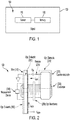
- Figure 1 depicts a schematic view of a sensor system 100, according to an embodiment.
- the sensor system 100 may be used, for example, in pharmaceutical supply chains, electronic and/or consumer goods, environmental monitoring, in-wall/in-build leak detection, and the like.
- the sensor system 100 may include a sensor 110 that is configured to measure one or more parameters.
- the parameters may be or include physical attributes having a value associated therewith. More particularly, the parameters may be or include temperature, pressure, humidity, moisture, vibration, shock, light, oxygen, the pressure or concentration of a gas, pH, salinity, the concentration of one or more dissolved ions, the concentration of one or more small molecules, or the concentration of one or more bio-molecules (e.g.
- the parameters may be related to an object 130.
- the object 130 may be a package of food that is intended to remain frozen, and the sensor 110 may be configured to measure a temperature of the package of food to monitor whether it remains frozen.
- the sensor system 100 may also include a memory (also referred to as a memory element) 120 that is connected to the sensor 110.
- the memory 120 may be configured to record (e.g., store) the parameter measured by the sensor 110. More particularly, the memory 120 may be configured to record the parameter measured by the sensor 110 when the parameter is outside of a predetermined range. Alternatively, the memory 120 may be configured to record the occurrence of a sensor excursion ( i.e ., that the parameter measured by sensor 110 is outside of a predetermined range) with or without recording the exact value or degree of the excursion. Continuing with the example above, the memory 120 may be configured to record when the parameter ( e.g., temperature) exceeds an upper threshold ( e.g., 0 °C). The memory 120 may also or instead be configured to record when the parameter ( e.g ., temperature) falls below a lower threshold. In at least one embodiment, multiple memory elements 120 can be connected to the same sensor 110 to monitor multiple upper and/or lower sensor limits.
- Figure 2 depicts a schematic view of the memory 120 of the sensor system 100, according to an embodiment.
- the memory 120 may be or include an electrochemical cell.
- the memory 120 may include a wire 210, a counter-electrode 220, and an electrolyte 230.
- the wire 210 may be or include a conductor defining a length, and the length may be formable into a closed perimeter.
- the wire 210 can undergo electrochemical reactions that change a property of the wire 210.
- the property may be or include a physical attribute of the wire 210 having a value associated therewith.
- the (physical attribute of the) property may differ from the (physical attribute of the) parameter.
- the property may be or include resistance/conductance, impedance, capacitance, inductance, color, or a combination thereof.
- the wire 210 can be metallic or semiconducting, and can include metals, organic semi-metals, inorganic semi-metals, organic semiconductors, polymeric semiconductors, and inorganic semiconductors. More particularly, the wire 210 may include silver, copper, aluminum, silicon, nickel, carbon, alloys thereof, or a combination thereof. Alternatively, the wire 210 may include PEDOT:PSS. As used herein, PEDOT:PSS refers to poly(3,4-ethylenedioxythiophene) polystyrene sulfonate, which may be or include a polymer mixture of two ionomers.
- the wire 210 may be or include a printed silver wire with a width between about 20 ⁇ m and about 500 ⁇ m.
- the wire 210 can be fabricated on a substrate using a wide variety of approaches, including various printing techniques (e.g ., inkjet, gravure, flexography, screen, xerography, laser, etc.), electrodeposition, electroless deposition, sputtering, evaporation, and lamination, among others.
- the counter-electrode 220 may be or include an electrode in a multi (e.g., three) electrochemical cell for voltammetric analysis or other reactions in which an electric current flows.
- the counter-electrode 220 may be or include a material that can be oxidized or reduced.
- the counter-electrode 220 may serve as a current-collector that allows the electrolyte 230 or a species dissolved in the electrolyte 230 to be oxidized or reduced.
- the counter-electrode 220 may include a wide range of redox-active materials, including ferricyanide/ferrocyanide, iodide, triiodide, viologen and its derivatives, viologen and its derivatives, metals and their salts (e.g ., silver, aluminum, gold, copper, nickel), redox-active inorganic solids (e.g ., Prussian blue, intercalation materials, metal oxides, metal phosphates).
- the counter-electrode 120 may be or include printed PEDOT:PSS.
- the electrolyte 230 may be or include a liquid or gel that contains ions and can be decomposed by electrolysis.
- the electrolyte 230 may be or include water with dissolved salt (e.g., NaNO 3 , Na 2 SO 4 , NaCl, and others), an organic solvent with dissolved salt, a polymer with dissolved salt, an ionically conductive inorganic solid, an ionic liquid, or mixtures or composites thereof.
- the electrolyte 230 may be or include 0.1 M NaNO 3 in water, adjusted to pH ⁇ 3 with nitric acid.
- the conductivity of the electrolyte 230 may be a function of the measured parameter (e.g ., humidity, moisture, temperature, etc.), and the corrosion current I corr may also be controlled via changes in the conductivity of the electrolyte 230, instead of or in addition to changes in the input voltage V in .
- the corrosion current I corr and the input voltage V in are described in greater detail below.
- a membrane 250 may be placed between the wire 210 and the counter-electrode 220 that allows the flow of at least some ions between two separate regions of the electrolyte 230.
- the membrane 250 may be or include a thin, soft, pliable sheet or layer.
- the membrane 250 may be or include an ion-selective membrane, an ion-conductive glass, or a polymer membrane.
- a dielectric layer 260 may be used to isolate the leads of the wire 210 and/or the counter-electrode 220 from the electrolyte 230.
- the dielectric layer 260 may be or include an electrical insulator that can be polarized by an applied electrical field.
- the dielectric layer 260 may be or include any suitable organic or inorganic material that blocks the electrolyte 230 from reaching the leads.
- the dielectric layer 260 may be or include tape that is used to isolate the leads of the wire 210 from the electrolyte 230.
- a polymer coating or plastic laminate may be used as the dielectric layer 260.
- the sensor 110 may output a voltage which may be a function of the measured parameter (e.g ., temperature).
- the output voltage may be directly proportional to, inversely proportional to, or dependent in a non-linear manner on the parameter.
- the voltage from the sensor 110 may be received at the memory 120 as an input voltage ( V in ), as shown in Figure 2 .
- V in an input voltage
- the input voltage V in may be connected to ( e.g., between) the wire 210 and the counter-electrode 220.
- the input voltage V in may cause an electrical current ( I corr ) between the wire 210 and the counter-electrode 220. At least a portion of the electrical current I corr (e.g., a net flow of electrons) may be participating at electrochemical reactions at the wire 210 and counter-electrode 220. These electrochemical reactions may cause a measurable property of the wire 210 to change, including resistance/conductance, impedance, capacitance, inductance, color, or a combination thereof. The rate of the electrochemical reactions is dependent on the input voltage V in and thus the measured parameter (e.g ., temperature).
- I corr electrical current between the wire 210 and the counter-electrode 220. At least a portion of the electrical current I corr (e.g., a net flow of electrons) may be participating at electrochemical reactions at the wire 210 and counter-electrode 220. These electrochemical reactions may cause a measurable property of the wire 210 to change, including resistance/conductance, imped
- the predetermined range for the parameter can be shifted by inverting the polarity of the sensor input (i.e., connecting the sensor's positive terminal to the negative terminal of V in ) and/or adding constant voltage-sources in series with the sensor 110 (as described below and depicted in Figures 6B and 6C ).
- the half reaction occurring at the wire 210 may include an oxidation or reduction that results in an irreversible change in the carrier mobility within the wire 210, such as the over-oxidation of PEDOT:PSS.
- the half reaction occurring at the wire 210 may generate gas bubbles, which in turn mechanically damage the wire 210 and reduce its conductivity.
- the reaction occurring at the wire 210 may be an electroplating or electrodeposition reaction that changes the properties of the wire 210.
- a second half-reaction may occur at/in the counter-electrode 220, which may be or include any oxidation or reduction reaction.
- the electrical current I corr and/or the half-reactions may cause metal corrosion in the wire 210.
- the metal corrosion in the wire 210 may cause one or more properties of the memory 120 to change.
- the metal corrosion in the wire 210 may cause one or more properties of the wire 210 to change.
- the properties of the wire 210 that change may be or include, for example, resistance, conductance, impedance, capacitance, inductance, color, or a combination thereof.
- the resistance of the wire 210 may increase, and the conductance of the wire 210 may decrease.
- the input voltage V in received from the sensor 110 may generate an electrical current I corr that causes one or more half-reactions in the memory 120.
- the half-reactions may cause the wire 210 to corrode.
- the corrosion varies the property of the wire 210 ( e.g., causes the resistance to increase and/or the conductance to decrease).
- a user may then be able to measure the property of the memory 120.
- the user may connect a measurement device (e.g., a radio-frequency identification (RFID) circuit) 240 to the wire 210 to measure the electrical current ( I wire ) through the wire 210 to determine the resistance and/or conductance of the wire 210.
- RFID radio-frequency identification
- the measured property e.g ., resistance and/or conductance
- the measured property may indicate current and/or past occurrences of the measured parameter being outside of the predetermined range.
- Figure 3A depicts a graph 300 showing the electrical current I wire through the wire 210 versus time at different input voltage V in values, according to an embodiment.
- the measurement device 240 applies a 10 mV bias voltage across the wire 210 while the input voltage V in applied to the counter-electrode 220 is varied.
- Figure 3B depicts a graph 350 showing the graph 300 of Figure 3A extended over a greater time duration, according to an embodiment.
- the user may conclude that the parameter was measured outside of the predetermined range by the sensor 110 at least once due to the decreased conductance of the wire 210.
- the decrease in the conductance of the wire 210 is substantially irreversible.
- the irreversible change in the conductance of the wire 210 can be obtained in two ways: 1) by selecting electrolytes 230 that react with silver ions to deposit oxidized silver compounds that are electrically isolated from the silver wire 210, thus preventing their later reduction back to metallic silver; and 2) using an irreversible counter-electrode reaction to limit the backwards current during voltage reversals.
- Figure 4 illustrates results of a different example where the change in the conductance of the wire 210 is reversible. More particularly, Figure 4 depicts a graph 400 showing the electrical current I wire through the wire 210 versus time at different voltage values V in , according to an embodiment.
- the conductance of the wire 210 in Figure 4 is at least partially reversible.
- the electrical current I wire increases, but to a lesser value than the previous time.
- the electrical current I wire increases to about 0.6 mA after the reversal of the first redox-reaction, and increases to about 0.3 mA after the reversal of the second redox-reaction.
- the value of the electrical current I wire may directly correspond with the number of times that the parameter (e.g ., temperature) is measured outside of the predetermined range ( e.g., exceeds 0°C).
- Figures 5A-5D show the voltage-dependence of the corrosion rate and power consumption of the memory 120. More particularly, Figure 5A illustrates a graph 510 showing the electrical current I wire for different input voltages V in , according to an embodiment.
- Figure 5B illustrates a graph 520 showing the time required for a 5% decrease in the electrical current I wire as a function of the input voltage V in , according to an embodiment.
- Figure 5C illustrates a graph 530 showing the average electrical current I corr versus the input voltage V in , according to an embodiment.
- Figure 5D illustrates a graph 540 showing the total charge required for complete corrosion of the wire 210 versus the input voltage V in , according to an embodiment.
- This strong voltage-dependence allows the sensor system 100 to be used as a sensitive irreversible threshold sensor, with moderate sensor output voltages leading to little or no decrease in conductance, and slightly more extreme sensor outputs causing rapid and irreversible changes in device conductance.
- the relative rate of switching/corrosion can be further tuned by adding a resistor 270 between the input voltage V in and the counter-electrode 220, by tuning the geometry of the memory 120, and/or by changing the conductivity electrolyte 230.
- the resistor 270 may have a resistance between about 10 Ohms and about 10 MOhms.
- the current-consumption of the memory 120 was extremely low (e.g., ⁇ 200 nA) at input voltages V in that indicated that the measured parameter was within the predetermined range, and thus little change in resistance occurs.
- these input voltages V in are about 0.0 ⁇ V in ⁇ -0.5 V).
- the electrical current consumption increased with decreasing input voltage V in , with the average electrical current in the range of 5-50 ⁇ A.
- the total charge required to completely corrode the silver wire 120 was approximately constant at 10-30 ⁇ Ah for moderate input voltages V in ( e.g., -0.75 V to -0.9 V), and approached 1 mAh at more negative input voltages V in , due to additional current-consumption by side-reactions.
- the power consumption can be controlled by designing the sensor system 100 to limit these side reactions by limiting the minimum and/or maximum input voltage V in and/or selecting electrode materials and electrolytes 130 that minimize side reactions. Further improvement in current-consumption at both active and inactive input voltages can be achieved via device miniaturization.
- Figure 6A illustrates another sensor system 600A including a sensor 610 and a memory 620, according to an embodiment.
- the memory 620 may be or include an electrochemical cell.
- the memory 620 may be similar to the memory 120 described above.
- the memory 620 is connected to a common ground shared by the sensor 610 and measurement and communication circuits 612.
- the sensor memory 620 also accepts an input voltage, V in , which may be connected to the output voltage, V out , of the sensor 610.
- V in an input voltage
- V out the output voltage
- the sensor memory 620 undergoes a measurable change in an electrical property that can be measured by the measurement and communication circuit 612 of the sensor 610.
- the measurement and communication circuit 612 can be powered on intermittently to measure the properties of the sensor memory 620. This is accomplished by providing a voltage (AC or DC) Meas which is applied to the V meas terminal of the sensor memory 620. Changes in the sensor memory 620 electrical properties can be deduced from changes in the electrical current that flows from Meas or changes in time constant for a charging/discharging voltage to be reached.
- a voltage AC or DC
- Changes in the sensor memory 620 electrical properties can be deduced from changes in the electrical current that flows from Meas or changes in time constant for a charging/discharging voltage to be reached.
- Figure 6B illustrates another sensor system 600B, according to an embodiment.
- the sensor system 600B may include one or more electrochemical cells (two are shown: 620A and 620B) placed in series with an optional voltage-offset cell 630.
- the electrochemical cells 620A, 620B are specifically chosen to exhibit a stimulus-dependent open-circuit voltage. For example, by selecting a redox-couple with a highly temperature-dependent redox potential (e.g ., ferrocyanide/ferricyanide) as part of the electrochemical cell 620A, 620B, the voltage of each cell 620A, 620B may be a function of temperature.
- a redox-couple with a highly temperature-dependent redox potential e.g ., ferrocyanide/ferricyanide
- the electrochemical cell 620A, 620B Ag/AgCl/3M NaCl//10 mM K 3 FeCN 6 , 10 mM K 4 FeCN 6 , 0.1 M NaCl/Pt exhibits an open-circuit voltage of 254 mV - (1.68 mV/°C)(T - 25 °C), where T is the temperature in °C.
- Figure 6C illustrates a graph 650 showing the total output voltage of the sensor system 600B from Figure 6B when different offset voltages and circuit polarities are used.
- Line 652 corresponds to the same cell as line 651, but with an offset voltage of -3.2 V. This increases the onset temperature to -30 °C.
- sensors that induce corrosion when a lower temperature limit is reached can also be prepared by inverting the polarity of the temperature-sensitive cells (positive electrode connected to ground).
- lines 653 and 654 correspond to the sensor circuit configured with ten temperature-sensitive cells and offset voltages of +2 and +1.7 V, respectively. If connected to the memory 120 from Figure 2 , these sensors would induce corrosion for T ⁇ 12 °C and ⁇ 30 °C, respectively.
- memory input voltages below the line 656 may lead to a measurable change in resistance.
- one or more of the acts depicted herein may be carried out in one or more separate acts and/or phases.
- the terms “including,” “includes,” “having,” “has,” “with,” or variants thereof are used in either the detailed description and the claims, such terms are intended to be inclusive in a manner similar to the term “comprising.”
- the term “at least one of' is used to mean one or more of the listed items may be selected.
- the term “on” used with respect to two materials, one “on” the other means at least some contact between the materials, while “over” means the materials are in proximity, but possibly with one or more additional intervening materials such that contact is possible but not required.
Landscapes
- Chemical & Material Sciences (AREA)
- Life Sciences & Earth Sciences (AREA)
- Health & Medical Sciences (AREA)
- Physics & Mathematics (AREA)
- General Physics & Mathematics (AREA)
- Chemical Kinetics & Catalysis (AREA)
- Electrochemistry (AREA)
- Molecular Biology (AREA)
- Analytical Chemistry (AREA)
- Biochemistry (AREA)
- General Health & Medical Sciences (AREA)
- Immunology (AREA)
- Pathology (AREA)
- Semiconductor Memories (AREA)
- Investigating Or Analyzing Materials By The Use Of Electric Means (AREA)
Abstract
Description
- The present teachings relate generally to a memory for a sensor and, more particularly, to a low-power memory for a sensor that can record past and present occurrences of a measurement by the sensor that is outside of a predetermined range.
- Continuous monitoring and/or logging of sensors with conventional electronics requires power (typically 10-100 µA even for conventional low-power electronics). As a result, sensors (also referred to herein as sensor tags) intended for continuous monitoring must include a battery or energy-harvesting element. This increases the cost and complexity of the sensors, thus limiting the available applications for the sensors. On the other hand, passively powered sensors such as near-field communication (NFC) sensors or radio-frequency identification (RFID) sensors can be operated without a battery. However, these sensors only provide information about the current sensor state (i.e., not past measurements).
- The following presents a simplified summary in order to provide a basic understanding of some aspects of one or more embodiments of the present teachings. This summary is not an extensive overview, nor is it intended to identify key or critical elements of the present teachings, nor to delineate the scope of the disclosure. Rather, its primary purpose is merely to present one or more concepts in simplified form as a prelude to the detailed description presented later.
- A sensor system is disclosed. The sensor system includes a sensor configured to measure a parameter. The sensor system also includes a memory configured to record one or more occurrences when the parameter is outside of a predetermined range. The memory includes a wire, a counter-electrode, and an electrolyte.
- In another embodiment, the sensor system includes a sensor configured to measure a parameter and to output a voltage that is a function of the parameter. The parameter is selected from the group consisting of temperature, pressure, humidity, moisture, vibration, shock, light, oxygen, concentration, pH, and salinity. The sensor system also includes a memory connected to the sensor. The memory includes a wire including a metal or a semiconductor. The memory also includes a counter-electrode including a redox-active material. The memory also includes an electrolyte in contact with the wire and the counter-electrode. The wire and the counter-electrode are configured to receive the voltage from the sensor. The voltage generates an electrical current between the wire and the counter-electrode. The electrical current causes an electrochemical reaction in the wire, the counter-electrode, or both when the parameter is outside of a predetermined range. The electrochemical reaction causes a property of the wire to change. The property is selected from the group consisting of resistance, conductance, impedance, capacitance, inductance, and color.
- In another embodiment, the sensor system includes a sensor configured to measure a parameter and to output a voltage that is a function of the parameter. The sensor system also includes a memory connected to the sensor. The memory includes an electrochemical cell. The memory is configured to record one or more past occurrences when the parameter is outside of a predetermined range without recording a value of the parameter. The memory includes a wire including silver. The memory also includes a counter-electrode including poly(3,4-ethylenedioxythiophene) polystyrene sulfonate. The memory also includes an electrolyte including sodium nitrate. The electrolyte is in contact with the wire and the counter-electrode. The memory also includes a membrane between the wire and the counter-electrode. The membrane allows a flow of ions between two separate regions of the electrolyte. The memory also includes a dielectric layer configured to isolate at least a portion of the wire or the counter-electrode from the electrolyte. The wire and the counter-electrode are configured to receive the voltage from the sensor. The voltage generates an electrical current between the wire and the counter-electrode. The electrical current causes an electrochemical reaction in the wire, the counter-electrode, or both when the parameter is outside of the predetermined range. The electrochemical reaction causes corrosion of the wire, which causes a conductance of the wire to decrease. A value of the conductance corresponds to a number of the occurrences when the parameter was outside of the predetermined range.
- The accompanying drawings, which are incorporated in and constitute a part of this specification, illustrate embodiments of the present teachings and together with the description, serve to explain the principles of the disclosure. In the figures:
-
Figure 1 depicts a schematic view of a sensor system, according to an embodiment. -
Figure 2 depicts a schematic view of a memory of the sensor system, according to an embodiment. -
Figure 3A depicts a graph showing the electrical current Iwire through the wire versus time at different input voltage Vin values, according to an embodiment. -
Figure 3B depicts a graph showing the graph ofFigure 3A extended over a greater time duration, according to an embodiment. -
Figure 4 depicts a graph showing the electrical current through the wire (Iwire ) versus time at different voltage values Vin , according to an embodiment. -
Figure 5A illustrates a graph showing the electrical current Iwire for different input voltages Vin , according to an embodiment. -
Figure 5B illustrates a graph showing the time required for a 5% decrease in the electrical current Iwire as a function of the input voltage Vin , according to an embodiment. -
Figure 5C illustrates a graph showing the average electrical current Icorr versus the input voltage Vin , according to an embodiment. -
Figure 5D illustrates a graph showing the total charge required for complete corrosion of the wire versus the input voltage Vin , according to an embodiment. -
Figure 6A illustrates another sensor system including a sensor and a memory, according to an embodiment. -
Figure 6B illustrates another sensor system, according to an embodiment. -
Figure 6C illustrates a graph showing the total output voltage of the sensor system fromFigure 6B when different offset voltages and circuit polarities are used, according to an embodiment. - Reference will now be made in detail to exemplary embodiments of the present teachings, examples of which are illustrated in the accompanying drawings. Wherever possible, the same reference numbers will be used throughout the drawings to refer to the same, similar, or like parts.
- The present disclosure is directed to a low-power, low-cost sensor system that can record the occurrence of one or more measurements by a sensor that is/are outside of a predetermined range (e.g., extreme sensor measurements). This allows a user to read the measurements with, for example, a measurement device (e.g., RFID reader) and obtain both current sensor measurements and past sensor measurements without requiring a discrete battery.
- The sensor system disclosed herein may provide the advantages of active sensor systems, passive sensor systems, and non-electric sensor systems (which have a property that changes when the measured parameter crosses a threshold). For example, the sensor system may enable wireless electronic monitoring of sensor history including past occurrences where the sensor measurements were outside of the predetermined range. The sensor system also requires no discrete battery or energy-harvesting elements beyond what is already present in existing RFID chips. Further, the sensor system can interface with any sensor that outputs a voltage (i.e., custom sensors don't have to be developed specifically to work with this sensor system). Moreover, the sensor system can be interfaced with both current and next-generation wireless communication protocols (i.e., protocol-agnostic).
-
Figure 1 depicts a schematic view of asensor system 100, according to an embodiment. Thesensor system 100 may be used, for example, in pharmaceutical supply chains, electronic and/or consumer goods, environmental monitoring, in-wall/in-build leak detection, and the like. Thesensor system 100 may include asensor 110 that is configured to measure one or more parameters. The parameters may be or include physical attributes having a value associated therewith. More particularly, the parameters may be or include temperature, pressure, humidity, moisture, vibration, shock, light, oxygen, the pressure or concentration of a gas, pH, salinity, the concentration of one or more dissolved ions, the concentration of one or more small molecules, or the concentration of one or more bio-molecules (e.g., DNA, RNA, peptides, proteins, carbohydrates, lipids). The parameters may be related to anobject 130. In one example, theobject 130 may be a package of food that is intended to remain frozen, and thesensor 110 may be configured to measure a temperature of the package of food to monitor whether it remains frozen. - The
sensor system 100 may also include a memory (also referred to as a memory element) 120 that is connected to thesensor 110. Thememory 120 may be configured to record (e.g., store) the parameter measured by thesensor 110. More particularly, thememory 120 may be configured to record the parameter measured by thesensor 110 when the parameter is outside of a predetermined range. Alternatively, thememory 120 may be configured to record the occurrence of a sensor excursion (i.e., that the parameter measured bysensor 110 is outside of a predetermined range) with or without recording the exact value or degree of the excursion. Continuing with the example above, thememory 120 may be configured to record when the parameter (e.g., temperature) exceeds an upper threshold (e.g., 0 °C). Thememory 120 may also or instead be configured to record when the parameter (e.g., temperature) falls below a lower threshold. In at least one embodiment,multiple memory elements 120 can be connected to thesame sensor 110 to monitor multiple upper and/or lower sensor limits. -
Figure 2 depicts a schematic view of thememory 120 of thesensor system 100, according to an embodiment. Thememory 120 may be or include an electrochemical cell. Thememory 120 may include awire 210, a counter-electrode 220, and anelectrolyte 230. Thewire 210 may be or include a conductor defining a length, and the length may be formable into a closed perimeter. Thewire 210 can undergo electrochemical reactions that change a property of thewire 210. The property may be or include a physical attribute of thewire 210 having a value associated therewith. The (physical attribute of the) property may differ from the (physical attribute of the) parameter. For example, the property may be or include resistance/conductance, impedance, capacitance, inductance, color, or a combination thereof. Thewire 210 can be metallic or semiconducting, and can include metals, organic semi-metals, inorganic semi-metals, organic semiconductors, polymeric semiconductors, and inorganic semiconductors. More particularly, thewire 210 may include silver, copper, aluminum, silicon, nickel, carbon, alloys thereof, or a combination thereof. Alternatively, thewire 210 may include PEDOT:PSS. As used herein, PEDOT:PSS refers to poly(3,4-ethylenedioxythiophene) polystyrene sulfonate, which may be or include a polymer mixture of two ionomers. In one example, thewire 210 may be or include a printed silver wire with a width between about 20 µm and about 500 µm. Thewire 210 can be fabricated on a substrate using a wide variety of approaches, including various printing techniques (e.g., inkjet, gravure, flexography, screen, xerography, laser, etc.), electrodeposition, electroless deposition, sputtering, evaporation, and lamination, among others. - The counter-electrode 220 may be or include an electrode in a multi (e.g., three) electrochemical cell for voltammetric analysis or other reactions in which an electric current flows. The counter-electrode 220 may be or include a material that can be oxidized or reduced. Alternatively, the counter-electrode 220 may serve as a current-collector that allows the
electrolyte 230 or a species dissolved in theelectrolyte 230 to be oxidized or reduced. The counter-electrode 220 may include a wide range of redox-active materials, including ferricyanide/ferrocyanide, iodide, triiodide, viologen and its derivatives, viologen and its derivatives, metals and their salts (e.g., silver, aluminum, gold, copper, nickel), redox-active inorganic solids (e.g., Prussian blue, intercalation materials, metal oxides, metal phosphates). In one example, the counter-electrode 120 may be or include printed PEDOT:PSS. - The
electrolyte 230 may be or include a liquid or gel that contains ions and can be decomposed by electrolysis. Theelectrolyte 230 may be or include water with dissolved salt (e.g., NaNO3, Na2SO4, NaCl, and others), an organic solvent with dissolved salt, a polymer with dissolved salt, an ionically conductive inorganic solid, an ionic liquid, or mixtures or composites thereof. For example, theelectrolyte 230 may be or include 0.1 M NaNO3 in water, adjusted to pH ∼3 with nitric acid. - In one embodiment the conductivity of the
electrolyte 230 may be a function of the measured parameter (e.g., humidity, moisture, temperature, etc.), and the corrosion current Icorr may also be controlled via changes in the conductivity of theelectrolyte 230, instead of or in addition to changes in the input voltage Vin. The corrosion current Icorr and the input voltage Vin are described in greater detail below. - A
membrane 250 may be placed between thewire 210 and the counter-electrode 220 that allows the flow of at least some ions between two separate regions of theelectrolyte 230. Themembrane 250 may be or include a thin, soft, pliable sheet or layer. For example, themembrane 250 may be or include an ion-selective membrane, an ion-conductive glass, or a polymer membrane. - A
dielectric layer 260 may be used to isolate the leads of thewire 210 and/or the counter-electrode 220 from theelectrolyte 230. Thedielectric layer 260 may be or include an electrical insulator that can be polarized by an applied electrical field. Thedielectric layer 260 may be or include any suitable organic or inorganic material that blocks theelectrolyte 230 from reaching the leads. For example, thedielectric layer 260 may be or include tape that is used to isolate the leads of thewire 210 from theelectrolyte 230. In another example, a polymer coating or plastic laminate may be used as thedielectric layer 260. - The
sensor 110 may output a voltage which may be a function of the measured parameter (e.g., temperature). The output voltage may be directly proportional to, inversely proportional to, or dependent in a non-linear manner on the parameter. The voltage from thesensor 110 may be received at thememory 120 as an input voltage (Vin ), as shown inFigure 2 . In the example above, as the temperature of theobject 130 increases, the input voltage Vin also increases, and as the temperature of theobject 130 decreases, the input voltage Vin also decreases. In another example, as the temperature of theobject 130 increases, the input voltage Vin decreases, and as the temperature of theobject 130 decreases, the input voltage Vin increases. The input voltage Vin may be connected to (e.g., between) thewire 210 and the counter-electrode 220. - The input voltage Vin may cause an electrical current (Icorr ) between the
wire 210 and the counter-electrode 220. At least a portion of the electrical current Icorr (e.g., a net flow of electrons) may be participating at electrochemical reactions at thewire 210 andcounter-electrode 220. These electrochemical reactions may cause a measurable property of thewire 210 to change, including resistance/conductance, impedance, capacitance, inductance, color, or a combination thereof. The rate of the electrochemical reactions is dependent on the input voltage Vin and thus the measured parameter (e.g., temperature). - For any combination of half-reactions occurring at the
wire 210 and the counter-electrode 220, there exists a range of input voltages Vin where the rate of the half-reactions is negligible. At input voltages Vin that are negative (e.g., for oxidation reactions occurring at the wire) or positive (e.g., for reduction reactions occurring at the wire) of this range, the rate of the electrochemical reactions is non-negligible, and a change in the wire's properties occurs. Thus, measured parameters that result in an input voltage Vin in this non-negligible voltage range are defined as being outside the predetermined range. For a givensensor 110 andmemory 120, the predetermined range for the parameter can be shifted by inverting the polarity of the sensor input (i.e., connecting the sensor's positive terminal to the negative terminal of Vin ) and/or adding constant voltage-sources in series with the sensor 110 (as described below and depicted inFigures 6B and 6C ). - In one embodiment, a first half-reaction may occur at/in the
wire 210, which may be or include oxidation of a metal (e.g., Ag => Ag+ + e- or Cu=> Cu2+ + 2 e-). In another embodiment, the half reaction occurring at thewire 210 may include an oxidation or reduction that results in an irreversible change in the carrier mobility within thewire 210, such as the over-oxidation of PEDOT:PSS. In yet another embodiment, the half reaction occurring at thewire 210 may generate gas bubbles, which in turn mechanically damage thewire 210 and reduce its conductivity. In yet another embodiment, the reaction occurring at thewire 210 may be an electroplating or electrodeposition reaction that changes the properties of thewire 210. In addition, a second half-reaction may occur at/in the counter-electrode 220, which may be or include any oxidation or reduction reaction. An illustrative reduction reaction may be or include a reduction of PEDOT (PEDOT+ + e- <==> PEDOT) followed by an irreversible reaction of reduced PEDOT with oxygen (in acidic media: 4 PEDOT + O2 + 4 H+ => 4 PEDOT+ + 2H2O and 2 PEDOT + O2 + 2 H+ => 2 PEDOT+ + H2O2). - The electrical current Icorr and/or the half-reactions may cause metal corrosion in the
wire 210. The metal corrosion in thewire 210 may cause one or more properties of thememory 120 to change. For example, the metal corrosion in thewire 210 may cause one or more properties of thewire 210 to change. The properties of thewire 210 that change may be or include, for example, resistance, conductance, impedance, capacitance, inductance, color, or a combination thereof. For example, as the metal corrosion in thewire 210 increases, the resistance of thewire 210 may increase, and the conductance of thewire 210 may decrease. - Thus, when the measured parameter is outside of the predetermined range (e.g., greater than 0°C), the input voltage Vin received from the
sensor 110 may generate an electrical current Icorr that causes one or more half-reactions in thememory 120. The half-reactions may cause thewire 210 to corrode. The corrosion varies the property of the wire 210 (e.g., causes the resistance to increase and/or the conductance to decrease). - A user may then be able to measure the property of the
memory 120. For example, the user may connect a measurement device (e.g., a radio-frequency identification (RFID) circuit) 240 to thewire 210 to measure the electrical current (Iwire ) through thewire 210 to determine the resistance and/or conductance of thewire 210. As described in greater detail below, the measured property (e.g., resistance and/or conductance) may indicate current and/or past occurrences of the measured parameter being outside of the predetermined range. - More particularly,
Figure 3A depicts agraph 300 showing the electrical current Iwire through thewire 210 versus time at different input voltage Vin values, according to an embodiment. In the example shown inFigure 3A , themeasurement device 240 applies a 10 mV bias voltage across thewire 210 while the input voltage Vin applied to the counter-electrode 220 is varied. The electrical current Iwire through thewire 210 remained relatively constant at Vin = 0.0, Vin = -0.1, and Vin = -0.5 V. However, the electrical current Iwire through thewire 210 decreased rapidly (e.g., to 0 mA) at Vin = -1.0 V. The values Vin = 0.0, Vin = -0.1, and Vin = -0.5 V correspond to the measured parameter being within the predetermined range, and the value Vin = -1.0 V corresponds to the measured parameter being outside of the predetermined range. -
Figure 3B depicts agraph 350 showing thegraph 300 ofFigure 3A extended over a greater time duration, according to an embodiment. Thegraph 350 includes the application of Vin = 0 V and Vin = 0.5 V after the electrical current Iwire drops to 0 mA. As may be seen, the application of Vin = 0 V and Vin = 0.5 V does not increase the conductance of thewire 210, as the electrical current Iwire remains 0 mA. As a result, when a user views the readings from the measurement device 240 (e.g., in the graph 350), the user may conclude that the parameter was measured outside of the predetermined range by thesensor 110 at least once due to the decreased conductance of thewire 210. - In this example, the decrease in the conductance of the
wire 210 is substantially irreversible. The irreversible change in the conductance of thewire 210 can be obtained in two ways: 1) by selectingelectrolytes 230 that react with silver ions to deposit oxidized silver compounds that are electrically isolated from thesilver wire 210, thus preventing their later reduction back to metallic silver; and 2) using an irreversible counter-electrode reaction to limit the backwards current during voltage reversals. -
Figure 4 illustrates results of a different example where the change in the conductance of thewire 210 is reversible. More particularly,Figure 4 depicts agraph 400 showing the electrical current Iwire through thewire 210 versus time at different voltage values Vin , according to an embodiment. The example ofFigure 4 involves a reversible redox-reaction at the counter-electrode 220 (e.g., 3 I- <=> I2 + I- + 2 e-). - As shown, an input voltage of Vin = -0.2 V is applied at time = 0 minutes. This causes the electrical current Iwire through the
wire 210 to decrease rapidly to 0 mA, as inFigures 3A and 3B . However, when higher input voltages Vin are applied, the decrease in the conductance of thewire 210 may be at least partially reversed. More particularly, a subsequent input voltage of Vin = +0.6 V at time = 20 minutes causes the electrical current Iwire to increase to about 0.6 mA. Thus, unlike the example shown inFigures 3A and 3B , the conductance of thewire 210 inFigure 4 is at least partially reversible. Another input voltage of Vin = -0.2 V is applied at time = 40 minutes and causes the electrical current Iwire to again decrease rapidly to 0 mA. Another input voltage of Vin = +0.6 V at time = 80 minutes causes the electrical current Iwire to increase to about 0.3 mA. - In this example, the value Vin = +0.6 V corresponds to the measured parameter being within the predetermined range, and the value Vin = -0.2 V corresponds to the measured parameter being outside of the predetermined range. For example, after an input voltage of Vin = -0.2 V causes the conductance and the electrical current Iwire to decrease, the subsequent input voltage of Vin = +0.6 V may cause plating to occur on the
wire 210, which may cause the conductance and the electrical current Iwire to increase. - In addition, as may be seen in
Figure 4 , each time the redox-reaction at the counter-electrode 220 is reversed, the electrical current Iwire increases, but to a lesser value than the previous time. For example, the electrical current Iwire increases to about 0.6 mA after the reversal of the first redox-reaction, and increases to about 0.3 mA after the reversal of the second redox-reaction. In at least one embodiment, the value of the electrical current Iwire may directly correspond with the number of times that the parameter (e.g., temperature) is measured outside of the predetermined range (e.g., exceeds 0°C). For example, a value of Iwire = 0.6 mA may indicate that the parameter was measured outside the predetermined range one time, a value of Iwire = 0.3 mA may indicate that the parameter was measured outside the predetermined range two times, a value of Iwire = 0.2 mA may indicate that the parameter was measured outside the predetermined range three times, and so on. -
Figures 5A-5D show the voltage-dependence of the corrosion rate and power consumption of thememory 120. More particularly,Figure 5A illustrates agraph 510 showing the electrical current Iwire for different input voltages Vin , according to an embodiment.Figure 5B illustrates agraph 520 showing the time required for a 5% decrease in the electrical current Iwire as a function of the input voltage Vin , according to an embodiment.Figure 5C illustrates agraph 530 showing the average electrical current Icorr versus the input voltage Vin , according to an embodiment.Figure 5D illustrates agraph 540 showing the total charge required for complete corrosion of thewire 210 versus the input voltage Vin , according to an embodiment. - As shown in
Figures 5A and 5B , the corrosion rate was a strong function of the input voltage Vin , with thesilver wire 210 losing about 5% of its conductance in 3,300 seconds with the input voltage Vin = -0.5 V, and 340 seconds with the input voltage Vin = -0.75 V. This strong voltage-dependence allows thesensor system 100 to be used as a sensitive irreversible threshold sensor, with moderate sensor output voltages leading to little or no decrease in conductance, and slightly more extreme sensor outputs causing rapid and irreversible changes in device conductance. The relative rate of switching/corrosion can be further tuned by adding aresistor 270 between the input voltage Vin and the counter-electrode 220, by tuning the geometry of thememory 120, and/or by changing theconductivity electrolyte 230. Theresistor 270 may have a resistance between about 10 Ohms and about 10 MOhms. - Furthermore, the current-consumption of the
memory 120 was extremely low (e.g., <200 nA) at input voltages Vin that indicated that the measured parameter was within the predetermined range, and thus little change in resistance occurs. In the examples above, these input voltages Vin are about 0.0 ≥ Vin ≥ -0.5 V). When the input voltage Vin was sufficiently negative to allow corrosion of thewire 210, the electrical current consumption increased with decreasing input voltage Vin , with the average electrical current in the range of 5-50 µA. As shown inFigure 5D , the total charge required to completely corrode thesilver wire 120 was approximately constant at 10-30 µAh for moderate input voltages Vin (e.g., -0.75 V to -0.9 V), and approached 1 mAh at more negative input voltages Vin , due to additional current-consumption by side-reactions. Thus, the power consumption can be controlled by designing thesensor system 100 to limit these side reactions by limiting the minimum and/or maximum input voltage Vin and/or selecting electrode materials andelectrolytes 130 that minimize side reactions. Further improvement in current-consumption at both active and inactive input voltages can be achieved via device miniaturization. -
Figure 6A illustrates anothersensor system 600A including asensor 610 and amemory 620, according to an embodiment. Thememory 620 may be or include an electrochemical cell. Thememory 620 may be similar to thememory 120 described above. Thememory 620 is connected to a common ground shared by thesensor 610 and measurement andcommunication circuits 612. Thesensor memory 620 also accepts an input voltage, Vin , which may be connected to the output voltage, Vout, of thesensor 610. When the parameter being measured by thesensor 610 is out of a predetermined range, thesensor memory 620 undergoes a measurable change in an electrical property that can be measured by the measurement andcommunication circuit 612 of thesensor 610. The measurement andcommunication circuit 612 can be powered on intermittently to measure the properties of thesensor memory 620. This is accomplished by providing a voltage (AC or DC) Meas which is applied to the Vmeas terminal of thesensor memory 620. Changes in thesensor memory 620 electrical properties can be deduced from changes in the electrical current that flows from Meas or changes in time constant for a charging/discharging voltage to be reached. -
Figure 6B illustrates anothersensor system 600B, according to an embodiment. In this embodiment, thesensor system 600B may include one or more electrochemical cells (two are shown: 620A and 620B) placed in series with an optional voltage-offsetcell 630. Theelectrochemical cells electrochemical cell cell electrochemical cell -
Figure 6C illustrates agraph 650 showing the total output voltage of thesensor system 600B fromFigure 6B when different offset voltages and circuit polarities are used. For example, line 651 shows the output voltage for a circuit with ten of the temperature-sensitive cells memory 120 fromFigure 2 , the sensor described by line 651 would induce corrosion for T>∼12 °C. - Higher or lower onset temperatures can be achieved by changing the offset voltage Voffset. For example, line 652 corresponds to the same cell as line 651, but with an offset voltage of -3.2 V. This increases the onset temperature to -30 °C. On the other hand, sensors that induce corrosion when a lower temperature limit is reached can also be prepared by inverting the polarity of the temperature-sensitive cells (positive electrode connected to ground). For example, lines 653 and 654 correspond to the sensor circuit configured with ten temperature-sensitive cells and offset voltages of +2 and +1.7 V, respectively. If connected to the
memory 120 fromFigure 2 , these sensors would induce corrosion for T<∼12 °C and <∼30 °C, respectively. In one embodiment, memory input voltages below theline 656 may lead to a measurable change in resistance. - Notwithstanding that the numerical ranges and parameters setting forth the broad scope of the present teachings are approximations, the numerical values set forth in the specific examples are reported as precisely as possible. Any numerical value, however, inherently contains certain errors necessarily resulting from the standard deviation found in their respective testing measurements. Moreover, all ranges disclosed herein are to be understood to encompass any and all sub-ranges subsumed therein. For example, a range of "less than 10" may include any and all sub-ranges between (and including) the minimum value of zero and the maximum value of 10, that is, any and all sub-ranges having a minimum value of equal to or greater than zero and a maximum value of equal to or less than 10, e.g., 1 to 5.
- While the present teachings have been illustrated with respect to one or more implementations, alterations and/or modifications may be made to the illustrated examples without departing from the spirit and scope of the appended claims. For example, it may be appreciated that while the process is described as a series of acts or events, the present teachings are not limited by the ordering of such acts or events. Some acts may occur in different orders and/or concurrently with other acts or events apart from those described herein. Also, not all process stages may be required to implement a methodology in accordance with one or more aspects or embodiments of the present teachings. It may be appreciated that structural objects and/or processing stages may be added, or existing structural objects and/or processing stages may be removed or modified. Further, one or more of the acts depicted herein may be carried out in one or more separate acts and/or phases. Furthermore, to the extent that the terms "including," "includes," "having," "has," "with," or variants thereof are used in either the detailed description and the claims, such terms are intended to be inclusive in a manner similar to the term "comprising." The term "at least one of' is used to mean one or more of the listed items may be selected. Further, in the discussion and claims herein, the term "on" used with respect to two materials, one "on" the other, means at least some contact between the materials, while "over" means the materials are in proximity, but possibly with one or more additional intervening materials such that contact is possible but not required. Neither "on" nor "over" implies any directionality as used herein. The term "conformal" describes a coating material in which angles of the underlying material are preserved by the conformal material. The term "about" indicates that the value listed may be somewhat altered, as long as the alteration does not result in nonconformance of the process or structure to the illustrated embodiment. The terms "couple," "coupled," "connect," "connection," "connected," "in connection with," and "connecting" refer to "in direct connection with" or "in connection with via one or more intermediate elements or members." Finally, the terms "exemplary" or "illustrative" indicate the description is used as an example, rather than implying that it is an ideal. Other embodiments of the present teachings may be apparent to those skilled in the art from consideration of the specification and practice of the disclosure herein. It is intended that the specification and examples be considered as exemplary only, with a true scope and spirit of the present teachings being indicated by the following claims.
Claims (20)
- A sensor system, comprising:a sensor configured to measure a parameter; anda memory configured to record one or more occurrences when the parameter is outside of a predetermined range, wherein the memory comprises:a wire;a counter-electrode; andan electrolyte.
- The sensor system of claim 1, wherein the memory does not record a value of the parameter.
- The sensor system of claim 1, wherein:the wire comprises a conductor that is configured to undergo an electrochemical reaction that changes a property of the wire when the parameter is outside of the predetermined range;the counter-electrode comprises a redox-active material that is configured to be oxidized, reduced, or both when the parameter is outside of the predetermined range; andthe electrolyte comprises water with dissolved salt, an organic solvent with dissolved salt, a polymer with dissolved salt, an ionically conductive inorganic solid, or an ionic liquid.
- The sensor system of claim 1, further comprising a membrane positioned at least partially between the wire and the counter-electrode, wherein the membrane allows a flow of ions between two regions of the electrolyte, and wherein the membrane comprises an ion-selective membrane, an ion-conductive glass, or a polymer membrane.
- The sensor system of claim 1, further comprising a dielectric layer that is configured to isolate a portion of the wire from the electrolyte, a portion of the counter-electrode from the electrolyte, or both, wherein the dielectric layer comprises tape, a polymer coating, or a plastic laminate.
- The sensor system of claim 1, wherein the sensor outputs a voltage that is based at least partially upon the parameter, wherein the voltage is received at wire and the counter-electrode, wherein the voltage generates an electrical current between the wire and the counter-electrode, wherein the electrical current causes an electrochemical reaction in the wire, the counter-electrode, or both when the parameter is outside of the predetermined range, and wherein the electrochemical reaction causes a property of the wire to change.
- The sensor system of claim 6, wherein the electrochemical reaction comprises a half-reaction in the wire that comprises oxidation of the wire.
- The sensor system of claim 6, wherein the electrochemical reaction comprises a half-reaction in the wire that comprises oxidation or reduction that results in an irreversible change in a carrier mobility within the wire.
- The sensor system of claim 6, wherein the electrochemical reaction comprises a half-reaction in the wire that generates gas bubbles that mechanically damage the wire and decrease the property of the wire, and wherein the property comprises conductivity.
- The sensor system of claim 6, wherein the electrochemical reaction comprises a half-reaction in the wire that comprises an electroplating reaction or an electrodeposition reaction that changes the property of the wire.
- The sensor system of claim 6, wherein the electrochemical reaction comprises a half-reaction in the counter-electrode that comprises a reduction reaction.
- The sensor system of claim 6, wherein the electrochemical reaction comprises a reduction of poly(3,4-ethylenedioxythiophene) (PEDOT) followed by a substantially irreversible reaction of reduced PEDOT with oxygen.
- The sensor system of claim 6, wherein the change in the property is substantially irreversible.
- The sensor system of claim 6, wherein the change in the property is at least partially reversible.
- The sensor system of claim 14, wherein the property comprises conductance, wherein the conductance decreases from a first value to a second value in response to a first occurrence of the parameter being outside of the predetermined range, wherein the conductance is configured to subsequently be increased to a third value that is between than the first value and the second value in response to application of a voltage to the memory.
- A sensor system, comprising:a sensor configured to measure a parameter and to output a voltage that is a function of the parameter, wherein the parameter is selected from the group consisting of temperature, pressure, humidity, moisture, vibration, shock, light, oxygen, concentration, pH, and salinity; anda memory connected to the sensor, wherein the memory comprises:a wire comprising a metal or a semiconductor;a counter-electrode comprising a redox-active material; andan electrolyte in contact with the wire and the counter-electrode,wherein the wire and the counter-electrode are configured to receive the voltage from the sensor,wherein the voltage generates an electrical current between the wire and the counter-electrode,wherein the electrical current causes an electrochemical reaction in the wire, the counter-electrode, or both when the parameter is outside of a predetermined range,wherein the electrochemical reaction causes a property of the wire to change, andwherein the property is selected from the group consisting of resistance, conductance, impedance, capacitance, inductance, and color.
- The sensor system of claim 16, wherein the electrochemical reaction causes corrosion in the wire, which causes the property of the wire to change, and wherein the property comprises conductance.
- The sensor system of claim 17, wherein the changed conductance indicates one or more current or past occurrences when the parameter was outside of the predetermined range.
- The sensor system of claim 18, wherein a value of the conductance corresponds to a number of the occurrences when the parameter was outside of the predetermined range.
- A sensor system, comprising:a sensor configured to measure a parameter and to output a voltage that is a function of the parameter; anda memory connected to the sensor, wherein the memory comprises an electrochemical cell, wherein the memory is configured to record one or more past occurrences when the parameter is outside of a predetermined range without recording a value of the parameter, and wherein the memory comprises:a wire comprising silver;a counter-electrode comprising poly(3,4-ethylenedioxythiophene) polystyrene sulfonate;an electrolyte comprising sodium nitrate, wherein the electrolyte is in contact with the wire and the counter-electrode;a membrane between the wire and the counter-electrode, wherein the membrane allows a flow of ions between two separate regions of the electrolyte; anda dielectric layer configured to isolate at least a portion of the wire or the counter-electrode from the electrolyte,wherein the wire and the counter-electrode are configured to receive the voltage from the sensor,wherein the voltage generates an electrical current between the wire and the counter-electrode,wherein the electrical current causes an electrochemical reaction in the wire, the counter-electrode, or both when the parameter is outside of the predetermined range,wherein the electrochemical reaction causes corrosion of the wire, which causes a conductance of the wire to decrease, andwherein a value of the conductance corresponds to a number of the occurrences when the parameter was outside of the predetermined range.
Applications Claiming Priority (1)
| Application Number | Priority Date | Filing Date | Title |
|---|---|---|---|
| US16/726,192 US11674829B2 (en) | 2019-12-23 | 2019-12-23 | Low-power sensor memory |
Publications (1)
| Publication Number | Publication Date |
|---|---|
| EP3842794A1 true EP3842794A1 (en) | 2021-06-30 |
Family
ID=73726738
Family Applications (1)
| Application Number | Title | Priority Date | Filing Date |
|---|---|---|---|
| EP20212022.6A Withdrawn EP3842794A1 (en) | 2019-12-23 | 2020-12-04 | Sensor system comprising low-power memory |
Country Status (3)
| Country | Link |
|---|---|
| US (1) | US11674829B2 (en) |
| EP (1) | EP3842794A1 (en) |
| JP (1) | JP7438921B2 (en) |
Citations (4)
| Publication number | Priority date | Publication date | Assignee | Title |
|---|---|---|---|---|
| GB1331241A (en) * | 1969-09-20 | 1973-09-26 | Matsushita Electric Industrial Co Ltd | Repeatedly useable memory element |
| US20040256644A1 (en) * | 2001-11-30 | 2004-12-23 | Thomas Kugler | Electrochemical device |
| US20060076413A1 (en) * | 2004-08-27 | 2006-04-13 | Infineon Technologies Ag | Chip card and chip card security device |
| US20150332141A1 (en) * | 2014-05-13 | 2015-11-19 | Arizona Board Of Regents On Behalf Of Arizona State University | Redox active polymer devices and methods of using and manufacturing the same |
Family Cites Families (7)
| Publication number | Priority date | Publication date | Assignee | Title |
|---|---|---|---|---|
| WO1989001228A1 (en) * | 1987-07-28 | 1989-02-09 | Maxdem Incorporated | Electrically settable resistance device |
| US4965151A (en) * | 1989-01-24 | 1990-10-23 | Matsushita Electric Industrial Co., Ltd. | Solid-state electrochemical cell |
| DE19515524C2 (en) * | 1995-04-27 | 1999-09-09 | Private Uni Witten Herdecke Gm | Method and device for the continuous detection of at least one substance in a gaseous or liquid mixture by means of a sensor electrode |
| AT505495A1 (en) * | 2007-07-04 | 2009-01-15 | Arc Austrian Res Centers Gmbh | METHOD FOR IDENTIFYING AND QUANTIFYING ORGANIC AND BIOCHEMICAL SUBSTANCES |
| US8758584B2 (en) * | 2010-12-16 | 2014-06-24 | Sensor Innovations, Inc. | Electrochemical sensors |
| US11231387B2 (en) * | 2018-01-24 | 2022-01-25 | Msa Europe Gmbh | Stabilization of sensor signal in electrochemical gas sensors |
| EP3797305B1 (en) * | 2018-06-22 | 2025-02-19 | Université de Rennes | System and method for the estimation of physical parameters of a medium |
-
2019
- 2019-12-23 US US16/726,192 patent/US11674829B2/en active Active
-
2020
- 2020-12-01 JP JP2020199877A patent/JP7438921B2/en active Active
- 2020-12-04 EP EP20212022.6A patent/EP3842794A1/en not_active Withdrawn
Patent Citations (4)
| Publication number | Priority date | Publication date | Assignee | Title |
|---|---|---|---|---|
| GB1331241A (en) * | 1969-09-20 | 1973-09-26 | Matsushita Electric Industrial Co Ltd | Repeatedly useable memory element |
| US20040256644A1 (en) * | 2001-11-30 | 2004-12-23 | Thomas Kugler | Electrochemical device |
| US20060076413A1 (en) * | 2004-08-27 | 2006-04-13 | Infineon Technologies Ag | Chip card and chip card security device |
| US20150332141A1 (en) * | 2014-05-13 | 2015-11-19 | Arizona Board Of Regents On Behalf Of Arizona State University | Redox active polymer devices and methods of using and manufacturing the same |
Also Published As
| Publication number | Publication date |
|---|---|
| US11674829B2 (en) | 2023-06-13 |
| JP7438921B2 (en) | 2024-03-01 |
| US20210190551A1 (en) | 2021-06-24 |
| JP2021099318A (en) | 2021-07-01 |
Similar Documents
| Publication | Publication Date | Title |
|---|---|---|
| EP2287597B1 (en) | Electrochemical sensor | |
| US4929313A (en) | Amperometric electrochemical ion sensors and method for determining ion concentration | |
| JPH05502506A (en) | metal oxide electrode | |
| WO1997011360A1 (en) | Cell tester device employing a printed transparent electrically conductive electrode | |
| Fjeldly et al. | Fluoride electrodes with reversible solid‐state contacts | |
| CN102265449A (en) | Immersion sensor to protect battery | |
| US6828808B2 (en) | Long-life conductivity sensor system and method for using same | |
| US11674829B2 (en) | Low-power sensor memory | |
| Pincella et al. | Electrical properties of an organic memristive system | |
| EP2932249B1 (en) | An arrangement for an electrochemical measurement | |
| US6863792B1 (en) | Method of making electrochemical detectors based on iridium oxide | |
| US20110031119A1 (en) | Plastic potentiometric ion-selective sensor and fabrication thereof | |
| US5672440A (en) | Cell tester device employing a cathodically depositable metal ion electrolyte solution | |
| Ugwuoke et al. | Low-temperature processed metal oxides and ion-exchanging surfaces as pH sensor | |
| Vonau et al. | Conceptions, materials, processing technologies and fields of application for miniaturized electrochemical sensors with planar membranes | |
| Kalidoss et al. | Solid-state planar reference electrode with ion-selective electrodes for clinical diagnosis | |
| CN110573876B (en) | Diagnostic strips and diagnostic systems using diagnostic strips | |
| Dean et al. | A PCB environmental sensor for use in monitoring drought conditions in estuaries | |
| Ortega et al. | A printed and self-powered test strip for digital conductivity measurement of low volume liquid samples | |
| Chawang et al. | Investigation of pH Sensing in viscous salt-added solution by iridium oxide film | |
| Wang et al. | Enhanced ion sensing stability with nanotextured biosensors | |
| JP4203291B2 (en) | Electrochemical measurement method, comparative electrode and composite electrode | |
| EP4575481A1 (en) | Gas sensor comprising a graphene layer | |
| Migdalski et al. | A miniaturized and integrated galvanic cell for the potentiometric measurement of ions in biological liquids | |
| CN106953106B (en) | Microbattery design and diagnostics |
Legal Events
| Date | Code | Title | Description |
|---|---|---|---|
| PUAI | Public reference made under article 153(3) epc to a published international application that has entered the european phase |
Free format text: ORIGINAL CODE: 0009012 |
|
| STAA | Information on the status of an ep patent application or granted ep patent |
Free format text: STATUS: THE APPLICATION HAS BEEN PUBLISHED |
|
| AK | Designated contracting states |
Kind code of ref document: A1 Designated state(s): AL AT BE BG CH CY CZ DE DK EE ES FI FR GB GR HR HU IE IS IT LI LT LU LV MC MK MT NL NO PL PT RO RS SE SI SK SM TR |
|
| STAA | Information on the status of an ep patent application or granted ep patent |
Free format text: STATUS: REQUEST FOR EXAMINATION WAS MADE |
|
| 17P | Request for examination filed |
Effective date: 20220103 |
|
| RBV | Designated contracting states (corrected) |
Designated state(s): AL AT BE BG CH CY CZ DE DK EE ES FI FR GB GR HR HU IE IS IT LI LT LU LV MC MK MT NL NO PL PT RO RS SE SI SK SM TR |
|
| STAA | Information on the status of an ep patent application or granted ep patent |
Free format text: STATUS: EXAMINATION IS IN PROGRESS |
|
| 17Q | First examination report despatched |
Effective date: 20230627 |
|
| STAA | Information on the status of an ep patent application or granted ep patent |
Free format text: STATUS: THE APPLICATION IS DEEMED TO BE WITHDRAWN |
|
| 18D | Application deemed to be withdrawn |
Effective date: 20250701 |