EP3842724A1 - Heat exchanger and heat exchange system including the same - Google Patents
Heat exchanger and heat exchange system including the same Download PDFInfo
- Publication number
- EP3842724A1 EP3842724A1 EP20215167.6A EP20215167A EP3842724A1 EP 3842724 A1 EP3842724 A1 EP 3842724A1 EP 20215167 A EP20215167 A EP 20215167A EP 3842724 A1 EP3842724 A1 EP 3842724A1
- Authority
- EP
- European Patent Office
- Prior art keywords
- region
- heat exchanger
- heat exchange
- shell
- refrigerant
- Prior art date
- Legal status (The legal status is an assumption and is not a legal conclusion. Google has not performed a legal analysis and makes no representation as to the accuracy of the status listed.)
- Granted
Links
Images
Classifications
-
- F—MECHANICAL ENGINEERING; LIGHTING; HEATING; WEAPONS; BLASTING
- F28—HEAT EXCHANGE IN GENERAL
- F28D—HEAT-EXCHANGE APPARATUS, NOT PROVIDED FOR IN ANOTHER SUBCLASS, IN WHICH THE HEAT-EXCHANGE MEDIA DO NOT COME INTO DIRECT CONTACT
- F28D7/00—Heat-exchange apparatus having stationary tubular conduit assemblies for both heat-exchange media, the media being in contact with different sides of a conduit wall
- F28D7/0066—Multi-circuit heat-exchangers, e.g. integrating different heat exchange sections in the same unit or heat-exchangers for more than two fluids
-
- F—MECHANICAL ENGINEERING; LIGHTING; HEATING; WEAPONS; BLASTING
- F25—REFRIGERATION OR COOLING; COMBINED HEATING AND REFRIGERATION SYSTEMS; HEAT PUMP SYSTEMS; MANUFACTURE OR STORAGE OF ICE; LIQUEFACTION SOLIDIFICATION OF GASES
- F25B—REFRIGERATION MACHINES, PLANTS OR SYSTEMS; COMBINED HEATING AND REFRIGERATION SYSTEMS; HEAT PUMP SYSTEMS
- F25B39/00—Evaporators; Condensers
- F25B39/02—Evaporators
-
- F—MECHANICAL ENGINEERING; LIGHTING; HEATING; WEAPONS; BLASTING
- F28—HEAT EXCHANGE IN GENERAL
- F28D—HEAT-EXCHANGE APPARATUS, NOT PROVIDED FOR IN ANOTHER SUBCLASS, IN WHICH THE HEAT-EXCHANGE MEDIA DO NOT COME INTO DIRECT CONTACT
- F28D21/00—Heat-exchange apparatus not covered by any of the groups F28D1/00 - F28D20/00
- F28D21/0017—Flooded core heat exchangers
-
- F—MECHANICAL ENGINEERING; LIGHTING; HEATING; WEAPONS; BLASTING
- F28—HEAT EXCHANGE IN GENERAL
- F28D—HEAT-EXCHANGE APPARATUS, NOT PROVIDED FOR IN ANOTHER SUBCLASS, IN WHICH THE HEAT-EXCHANGE MEDIA DO NOT COME INTO DIRECT CONTACT
- F28D7/00—Heat-exchange apparatus having stationary tubular conduit assemblies for both heat-exchange media, the media being in contact with different sides of a conduit wall
- F28D7/16—Heat-exchange apparatus having stationary tubular conduit assemblies for both heat-exchange media, the media being in contact with different sides of a conduit wall the conduits being arranged in parallel spaced relation
- F28D7/1607—Heat-exchange apparatus having stationary tubular conduit assemblies for both heat-exchange media, the media being in contact with different sides of a conduit wall the conduits being arranged in parallel spaced relation with particular pattern of flow of the heat exchange media, e.g. change of flow direction
-
- F—MECHANICAL ENGINEERING; LIGHTING; HEATING; WEAPONS; BLASTING
- F28—HEAT EXCHANGE IN GENERAL
- F28F—DETAILS OF HEAT-EXCHANGE AND HEAT-TRANSFER APPARATUS, OF GENERAL APPLICATION
- F28F27/00—Control arrangements or safety devices specially adapted for heat-exchange or heat-transfer apparatus
-
- F—MECHANICAL ENGINEERING; LIGHTING; HEATING; WEAPONS; BLASTING
- F28—HEAT EXCHANGE IN GENERAL
- F28F—DETAILS OF HEAT-EXCHANGE AND HEAT-TRANSFER APPARATUS, OF GENERAL APPLICATION
- F28F9/00—Casings; Header boxes; Auxiliary supports for elements; Auxiliary members within casings
- F28F9/22—Arrangements for directing heat-exchange media into successive compartments, e.g. arrangements of guide plates
-
- F—MECHANICAL ENGINEERING; LIGHTING; HEATING; WEAPONS; BLASTING
- F25—REFRIGERATION OR COOLING; COMBINED HEATING AND REFRIGERATION SYSTEMS; HEAT PUMP SYSTEMS; MANUFACTURE OR STORAGE OF ICE; LIQUEFACTION SOLIDIFICATION OF GASES
- F25B—REFRIGERATION MACHINES, PLANTS OR SYSTEMS; COMBINED HEATING AND REFRIGERATION SYSTEMS; HEAT PUMP SYSTEMS
- F25B2339/00—Details of evaporators; Details of condensers
- F25B2339/02—Details of evaporators
- F25B2339/024—Evaporators with refrigerant in a vessel in which is situated a heat exchanger
-
- F—MECHANICAL ENGINEERING; LIGHTING; HEATING; WEAPONS; BLASTING
- F25—REFRIGERATION OR COOLING; COMBINED HEATING AND REFRIGERATION SYSTEMS; HEAT PUMP SYSTEMS; MANUFACTURE OR STORAGE OF ICE; LIQUEFACTION SOLIDIFICATION OF GASES
- F25B—REFRIGERATION MACHINES, PLANTS OR SYSTEMS; COMBINED HEATING AND REFRIGERATION SYSTEMS; HEAT PUMP SYSTEMS
- F25B2400/00—Component parts or details not otherwise provided for in this subclass
- F25B2400/01—Heaters
-
- F—MECHANICAL ENGINEERING; LIGHTING; HEATING; WEAPONS; BLASTING
- F28—HEAT EXCHANGE IN GENERAL
- F28D—HEAT-EXCHANGE APPARATUS, NOT PROVIDED FOR IN ANOTHER SUBCLASS, IN WHICH THE HEAT-EXCHANGE MEDIA DO NOT COME INTO DIRECT CONTACT
- F28D21/00—Heat-exchange apparatus not covered by any of the groups F28D1/00 - F28D20/00
- F28D2021/0019—Other heat exchangers for particular applications; Heat exchange systems not otherwise provided for
- F28D2021/0068—Other heat exchangers for particular applications; Heat exchange systems not otherwise provided for for refrigerant cycles
- F28D2021/0071—Evaporators
-
- F—MECHANICAL ENGINEERING; LIGHTING; HEATING; WEAPONS; BLASTING
- F28—HEAT EXCHANGE IN GENERAL
- F28F—DETAILS OF HEAT-EXCHANGE AND HEAT-TRANSFER APPARATUS, OF GENERAL APPLICATION
- F28F9/00—Casings; Header boxes; Auxiliary supports for elements; Auxiliary members within casings
- F28F9/22—Arrangements for directing heat-exchange media into successive compartments, e.g. arrangements of guide plates
- F28F2009/222—Particular guide plates, baffles or deflectors, e.g. having particular orientation relative to an elongated casing or conduit
- F28F2009/228—Oblique partitions
Definitions
- the present invention relates to the technical field of heat exchange, and in particular to a heat exchanger and a heat exchange system including the heat exchanger.
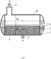
- FIG. 1 shows a side view of the structure of an existing flooded evaporator.
- a shell of such a flooded evaporator is mostly cylindrical and has a large spatial volume, wherein heat exchange tube bundles are installed at the bottom of the shell.
- the present invention provides a heat exchanger and a heat exchange system including the heat exchanger, which can solve or at least alleviate one or more of the above problems and other problems existing in the related art.
- the present invention provides a heat exchanger, which includes a shell having an inlet and an outlet, and heat exchange tube bundles arranged in the shell, wherein the shell is provided therein with:
- first region and the second region are arranged side by side in a length direction of the shell.
- the inlet and the outlet may be disposed under the first region and above the second region respectively.
- a ratio of a height of the heat exchange tube bundles to an internal height of the shell is not smaller than 0.5.
- a liquid height of the refrigerant in the first region is not smaller than a height of the heat exchange tube bundles.
- the heating device is an electric heater or at least one row of heat exchange tubes, and the heat exchange tubes may communicate with a fluid input end of the heat exchange tube bundles in the first region through a pipeline.
- the heating device is disposed at the bottom of the second region.
- a ratio of the height of the heating device to a height of the second region may not be larger than 0.5.
- the heat exchanger further includes a flow guiding member arranged at least between the first region and the second region for guiding the refrigerant flowing out of the first region after the heat exchange to flow toward the second region and/or the outlet.
- the heat exchanger further includes a liquid blocking member arranged at the outlet and configured to prevent a liquid-state refrigerant from flowing out of the shell.
- the flow guiding member is configured as a baffle having an arc shape.
- the liquid blocking member is configured as a wire mesh having a structure of at least two layers.
- the heat exchanger further includes a control device connected to the heating device and configured to control an operation of the heating device.
- the heat exchanger further includes a detection device connected to the control device and configured to detect parameter information of the refrigerant in the first region and provide the parameter information to the control device for the control device to control the operation of the heating device.
- a detection device connected to the control device and configured to detect parameter information of the refrigerant in the first region and provide the parameter information to the control device for the control device to control the operation of the heating device.
- the present invention provides a heat exchange system, which includes the heat exchanger according to any one of the above technical solutions described with reference to the first aspect of the invention.
- the embodiments of the present disclosure are easier to manufacture, install and maintain.
- the restrictions to spatial layout of the heat exchanger tube bundles in the conventional solutions are eliminated, so that the heat exchange tube bundles can be fully immersed into the refrigerant for heat exchange, which not only can effectively improve the utilization of shell space of the heat exchanger, but also can improve the heat transfer efficiency of the heat exchanger at the same material cost.
- the overall performance, safety and reliability of the system can be further enhanced, and adverse effects on other components, devices, or apparatuses (such as a compressor) associated with the heat exchanger can be avoided.
- substantially is intended to include non-substantive errors associated with the measurement of a specific amount (for example, it may include a range of ⁇ 8%, ⁇ 5%, or ⁇ 2% of a given value), and the technical terms “upper”, “lower”, “top”, “bottom”, “inner”, “outer”, “left”, “right” and derivatives thereof should be related to the orientations in the drawings; unless explicitly indicated otherwise, the present disclosure can take a variety of alternative orientations.
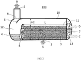
- FIG. 2 A general structure of a heat exchanger is schematically shown in FIG. 2 , and an exemplary description will be given below through this embodiment so that obvious technical advantages of the present disclosure over existing heat exchangers such as shown in FIG. 1 can be clearly understood.
- the heat exchanger 100 has a shell 10.
- the shell 10 may be configured to have any suitable shape such as a cylinder, a rectangular parallelepiped and the like according to specific application requirements.
- the shell 10 is provided with an inlet 1 and an outlet 2, and two different regions are disposed in the interior of the shell 10, namely a first region 11 and a second region 12, wherein heat exchange tube bundles 3 are arranged in the first region 11, and a heating device 4 is arranged in the second region 12.
- a baffle 8 may be provided and installed inside the shell 10 by means of connection such as welding, so that the above mentioned two regions 11 and 12 are formed. Such a baffle 8 may also support the heat exchange tube bundles 3 arranged in the first region 11. In practical applications, the number, the spacing of arrangement, the size, the shape and structure, the materials used and the like of the above baffle 8 and the heat exchange tube bundles 3 may also each be selected and set as required.
- arrows A and B are respectively used to schematically indicate that a refrigerant 7 (such as hydrofluoroolefin (HFO), hydrofluorocarbon (HFC), etc.) used for heat exchange enters the first region 11 of the shell 10 from the inlet 1, and finally leaves the shell 10 from the outlet 2 and enters other components, devices or apparatuses such as a compressor (not shown).
- arrows C and D are also respectively used to schematically indicate that another fluid (such as water, glycol, saline, etc.) will flow through the heat exchange tube bundles 3 arranged in the first region 11.
- a heat exchange process will be completed between the fluid and the above-mentioned refrigerant 7.
- the above-mentioned refrigerant 7 undergoes boiling heat transfer in the first region 11, and a part of the refrigerant 7 will be evaporated and then flow out from the first region 11 in a gaseous state (which may entrain a part of the refrigerant 7 in a gas-liquid mixed state). For example, it flows substantially toward the second region 12 in the example of FIG. 2 .
- the second region 12 is arranged between the above-mentioned first region 11 and the outlet 2, and it is in fluid communication with both the first region 11 and the outlet 2. In this way, after leaving the first region 11, the above-mentioned gaseous refrigerant 7 will flow through the second region 12 and then flow out of the heat exchanger 100 from the outlet 2.
- a heating device 4 for providing thermal energy is disposed in the second region 12.
- the heating device 4 may be installed at the bottom of the second region 12 or at any other suitable position so that the refrigerant 7 flowing out of the first region 1 can be heated and it can be more fully and thoroughly vaporized, and undesired damages to components, devices or apparatuses associated with the heat exchanger 100 such as the compressor caused by the possible entrained liquid are avoided.
- the refrigerant 7 input from the inlet 1 can be accommodated in the first region 11 formed by, for example, installing a baffle 8, during the heat exchange process between the refrigerant 7 and the fluid in the heat exchange tube bundles 3, there may be some refrigerant liquid splashing from the first region 11 into the second region 12 or entrained in the refrigerant vapor flowing out of the first region 11, that is, the refrigerant 7 entering the second region 12 from the first region 11 is mostly gaseous, but a part of the refrigerant 7 may be in a liquid state or a gas-liquid mixed state.
- the heating device 4 arranged in the second region 12 enables the refrigerant 7 in a liquid state or gas-liquid mixed state to be heated to enter a gaseous state as well after the temperature rise, thereby effectively preventing associated components, devices or apparatuses such as the compressor from being easily damaged by the liquid flowing out of the outlet 2.
- the above-mentioned heating device 4 may be implemented in many forms, such as an electric heating device, a hot-fluid (such as heat transfer oil, vapor, etc.) heating device, increased and enhanced heat exchange tube bundles, and the like.
- the heating device 4 may in some applications be arranged such that a ratio of a height of the heating device 4 to a height of the second region 12 is not larger than 0.5, so as to ensure that a more sufficient empty space is provided to accommodate the refrigerant 7 (which may be in a gaseous state, a liquid state, or a gas-liquid mixed state) flowing out of the first region 11 and that the refrigerant 7 can be sufficiently heated and evaporated during the stay.
- the above height ratio is in a value range of 0.3-0.5.
- the use of other ratios such as 0.1, 0.13, 0.2, 0.25 and the like is also possible and allowed in some application situations.
- the heat exchanger according to the present disclosure can overcome the restrictions to spatial layout of the heat exchanger tube bundles in the conventional solutions such as shown in FIG. 1 , and realize technical advantages that are significantly superior to existing heat exchangers.
- FIG. 2 a height of the heat exchange tube bundles 3 arranged in the first region 11 and a height of an empty space above the heat exchange tube bundles 3 are indicated by reference signs H and H2 respectively.
- the heat exchange tube bundles 3 may be arranged such that the ratio of the height H thereof to the internal height of the shell 10 (i.e., H+H2) is not smaller than 0.5, which will be significantly different from the conventional arrangement shown in FIG. 1 , and the restrictions to the layout of the heat exchanger tube bundles in such heat exchangers in the related art are overcome.
- the arrangement height H of the heat exchange tube bundles 3 is generally not larger than the height H1 of the empty space above the heat exchange tube bundle s3, that is, H will not exceed 0.6 times the height of the shell 10 (i.e. H+H1), i.e., H/(H+H1) ⁇ 0.6, so as to provide sufficient head space to avoid the above-mentioned LCO.
- the heat exchange tube bundles 3 are usually not completely immersed into the refrigerant 7 (i.e., H0 ⁇ H) to further avoid the occurrence of the above-mentioned LCO; that is, the height H0 of the refrigerant 7 should be smaller than the height H of the heat exchange tube bundles 3.
- the height of the empty space in the shell 10 of the heat exchanger 100 can be significantly reduced (that is, H2 ⁇ H1; for example, H2 may be only a half of HI, or less).
- a space utilization can be greatly improved, that is, more heat exchange tube bundles 3 can be arranged for heat exchange, given the same shell volume space.
- the present disclosure also allows the refrigerant 7 accommodated in the first region 11 to be completely immersed into the heat exchange tube bundles 3; that is, the height of the refrigerant 7 in the first region 11 may not be smaller than the height H of the heat exchange tube bundles 3, so that a more sufficient heat exchange effect can be obtained, which is completely unimaginable with the existing technology which will actually have to actively avoid the above situations.
- applying the heat exchanger of the present disclosure can significantly improve the heat transfer efficiency of the heat exchanger.
- both a flow guiding member 5 and a liquid blocking member 6 are further shown. They are provided as optional components in the shell 10 of the heat exchanger 100, that is, in some other examples, one of them may be omitted, or both of them may be omitted at the same time.
- the flow guiding member 5 may be arranged between the first region 11 and the second region 12 so as to guide the refrigerant 7 flowing out of the first region 11 to flow toward the second region 12 and/or the outlet 2.
- the flow guiding member 5 may be optionally configured as a baffle having an arc shape, and the use of such an arc-shaped baffle can promote the refrigerant 7 to flow from the first region 11 to the second region 12 via a substantially 90°-turn flow path, and then flow from the second region 12 toward the outlet 2 via a substantially 180°-turn flow path (or the range of flow direction change may be extended to any other angle between 0°-180°), thereby forming a very favorable heating-evaporation path, and promoting the liquid-state part of the refrigerant 7 to be more fully evaporated and vaporized.
- the flow guiding member 5 may also be arranged at any other suitable position, such as above the first region 11 and near the outlet 2 so that the flow of the refrigerant 7 inside the shell 10 can be guided as desired.
- the liquid blocking member 6 may be arranged at the outlet 2 of the shell 10 so as to prevent the liquid-state refrigerant 7 from flowing out of the shell 10, thereby preventing it from entering components, devices or apparatuses associated with the heat exchanger 100 such as the compressor and having an adverse effects on them.
- the above-mentioned liquid blocking member 6 may be implemented by using multiple layers of wire mesh.
- the liquid blocking member 6 is formed by using two or more layers of metal wire mesh to block the refrigerant liquid from flowing out of the heat exchanger 100. The blocked refrigerant liquid will then drip into the second region 12 and be further heated and evaporated.
- the heat exchanger 100 may be further configured with a control device (not shown).
- This type of control device may be implemented in many ways, for example by hardware components such as chips and processors, software, or a combination of software and hardware.
- the control device may be connected to the heating device 4 to control an operation of the heating device 4 according to the application requirements. For example, the heating device 4 may be turned on or off as needed, or the current operating power of the heating device 4 may be adjusted, or the heating device 4 may be regulated according to a preset cycle (such as distinguishing between working days and non-working days within a week) or a time period (such as working hours and non-working hours in a day).
- a detection device such as a liquid level sensor, a temperature sensor and the like may also be disposed in the heat exchanger 100 to detect and acquire parameter information (such as liquid level, temperature, etc.) of the refrigerant 7 in the first region 11 and then provide the parameter information to the control device discussed above so that the control device can control the operation of the heating device 4 based on such parameter information.
- parameter information such as liquid level, temperature, etc.
- the control device may be used to reduce the current operating power of the heating device 4, or temporarily turn off the heating device 4 for a period of time until it is determined that the heating device 4 needs to be turned on again according to the subsequently detected liquid level information.
- one or more detection devices may be arranged at appropriate positions in the shell 10 as required. These detection devices may collect the same type of parameters or different types of parameters, that is, the present disclosure allows a combined use of various types of detection devices at the same time, such as liquid level sensors, temperature sensors and the like.
- first region 11 and the second region 12 are arranged side by side in a length direction of the shell 10 in the embodiment shown in FIG. 2 , and the inlet 1 and the outlet 2 are disposed under the first region 11 and above the second region 12 respectively
- the present disclosure allows for any possible adjustment and change to the above layouts in different application environments.
- the inlet 1 may be arranged on a side of the first region 11; for another example, the outlet 2 may be arranged on a side of the second region 12; for further another example, the first region 11 shown in FIG. 2 is extended to be under the second region 12 so that the second region 12 is located above a part of the first region 11. This will facilitate the formation of a more compact structural layout, which is suitable for some sites with relatively limited installation space.
- the present disclosure allows the number of each of them provided at the same time to be two or more, which may be flexibly designed and adjusted according to the specific application requirements.
- FIG. 2 only exemplarily shows that the heat exchange tube bundles 3 may be in a form of two channels (that is, the fluid is input and output according to arrows C and D respectively), but in some applications, more fluid delivery forms such as a single channel, three channels, four channels and the like may be used.
- bulkheads 13 disposed at the ends of some heat exchangers may have any feasible configuration (such as a horizontal or inclined arrangement, a semi-ellipsoidal or semi-spherical shape, etc.), and may be used to define a path in which the fluid enters and leaves the heat exchange tube bundles 3, which has been exemplarily illustrated in FIG. 2 .
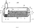
- FIG. 3 another heat exchanger is presented in FIG. 3 .
- the heat exchanger 200 unless otherwise specified below, for contents identical or similar to those in the example shown in FIG. 2 discussed above, since they have been described in great detail in the above, reference may be directly made to specific description in the foregoing corresponding parts in order to avoid repeated description.
- one or more rows of heat exchange tubes may be arranged in the second region 12 to serve as the heating device 4, and the above-mentioned heat exchange tubes may communicate with a fluid input end of the heat exchange tube bundles 3 in the first region 11 through a pipeline 9.
- a bypass line can be formed by the pipeline 9 to transfer the fluid having a higher temperature at the fluid input end to the heat exchange tubes in the second region 12 that can be formed as enhanced heat exchange tube bundles so that thermal energy is provided to the second region 12 to realize the heating and temperature rise as described above, thereby avoiding adverse effects on components, devices, or apparatuses (such as the compressor) associated with the heat exchanger 200 caused by possible entrained liquid.
- the above-mentioned heat exchange tubes are used as the heating device 4, and the operation of the heat exchange tubes may be controlled by providing the control device discussed above. For example, it may be implemented by controlling an on/off state, a flow/flow rate and the like of a flow path of the pipeline 9 by the control device as needed. After reading and understanding the present disclosure, those skilled in the art may adopt a number of means to specifically implement such a control, which will not be repeated herein.
- the bulkhead 13 at the left end of the heat exchanger 200 is also shown in FIG. 3 .
- the bulkhead 13 may be used to store fluid supplied to the heat exchange tubes in the second region 12 through the pipeline 9 for heat exchange, so as to fully ensure that the heat exchange tubes have a good, lasting and reliable heating function.
- a heat exchange system is further provided, which may for example be provided with the above exemplified heat exchanger designed and provided by the present disclosure.
- the heat exchanger may be used as a heat exchange device such as a flooded evaporator in the heat exchange system, so that the problems existing in the related art such as those mentioned above can be better solved, prominent technical advantages of the present disclosure discussed above which are significantly superior to the related art are obtained, and considerable economic benefits are achieved.
- the heat exchange system according to the present disclosure may for example include, but is not limited to, a heating, ventilation, and air conditioning (HVAC) system, a transportation refrigeration system, a freezing/refrigeration system, and the like.
- HVAC heating, ventilation, and air conditioning
Landscapes
- Engineering & Computer Science (AREA)
- Physics & Mathematics (AREA)
- Thermal Sciences (AREA)
- Mechanical Engineering (AREA)
- General Engineering & Computer Science (AREA)
- Heat-Exchange Devices With Radiators And Conduit Assemblies (AREA)
Abstract
Description
- The present invention relates to the technical field of heat exchange, and in particular to a heat exchanger and a heat exchange system including the heat exchanger.
- In the existing technologies, various types of heat exchange devices, apparatuses or systems have been provided, which have been widely used in many industrial fields, places, etc., and can bring great convenience. However, these existing heat exchange devices, apparatuses or systems still have some disadvantages and deficiencies in terms of structural configuration, heat exchange effect, working performance, manufacturing, installation and maintenance, etc., so there is a room for them to be further improved and optimized. For example,
FIG. 1 shows a side view of the structure of an existing flooded evaporator. A shell of such a flooded evaporator is mostly cylindrical and has a large spatial volume, wherein heat exchange tube bundles are installed at the bottom of the shell. Mainly due to the limitation by liquid carryover (LCO), the heat exchange tube bundles are restricted in spatial arrangement, resulting in a large empty space formed at the top of the shell. Therefore, the shell space is not most effectively utilized, and the heat exchange tube bundles cannot be sufficiently immersed into a refrigerant entering the shell to achieve better heat transfer efficiency, which affects further improvements on the overall performance, safety, reliability and the like of the system. - In view of the above, the present invention provides a heat exchanger and a heat exchange system including the heat exchanger, which can solve or at least alleviate one or more of the above problems and other problems existing in the related art.
- In a first aspect, the present invention provides a heat exchanger, which includes a shell having an inlet and an outlet, and heat exchange tube bundles arranged in the shell, wherein the shell is provided therein with:
- a first region communicating with the inlet and configured to accommodate the heat exchange tube bundles and a refrigerant input from the inlet, the refrigerant performing heat exchange with a fluid in the heat exchange tube bundles; and
- a second region arranged between the first region and the outlet and communicating with the first region and the outlet, a heating device being disposed in the second region.
- Optionally, the first region and the second region are arranged side by side in a length direction of the shell. The inlet and the outlet may be disposed under the first region and above the second region respectively.
- Optionally, a ratio of a height of the heat exchange tube bundles to an internal height of the shell is not smaller than 0.5.Optionally, a liquid height of the refrigerant in the first region is not smaller than a height of the heat exchange tube bundles.
- Optionally, the heating device is an electric heater or at least one row of heat exchange tubes, and the heat exchange tubes may communicate with a fluid input end of the heat exchange tube bundles in the first region through a pipeline.
- Optionally, the heating device is disposed at the bottom of the second region. A ratio of the height of the heating device to a height of the second region may not be larger than 0.5.
- Optionally, the heat exchanger further includes a flow guiding member arranged at least between the first region and the second region for guiding the refrigerant flowing out of the first region after the heat exchange to flow toward the second region and/or the outlet.
- Optionally, the heat exchanger further includes a liquid blocking member arranged at the outlet and configured to prevent a liquid-state refrigerant from flowing out of the shell.
- Optionally, the flow guiding member is configured as a baffle having an arc shape.
- Optionally, the liquid blocking member is configured as a wire mesh having a structure of at least two layers.
- Optionally, the heat exchanger further includes a control device connected to the heating device and configured to control an operation of the heating device.
- Optionally, the heat exchanger further includes a detection device connected to the control device and configured to detect parameter information of the refrigerant in the first region and provide the parameter information to the control device for the control device to control the operation of the heating device.
- In a second aspect, the present invention provides a heat exchange system, which includes the heat exchanger according to any one of the above technical solutions described with reference to the first aspect of the invention.
- From the following detailed description in combination with the accompanying drawings, the principles, features, characteristics, advantages and the like of the various embodiments of the present disclosure will be clearly understood. For example, as compared with related art, the embodiments of the present disclosure are easier to manufacture, install and maintain. By structurally optimizing and designing the shell space of the heat exchanger, the restrictions to spatial layout of the heat exchanger tube bundles in the conventional solutions are eliminated, so that the heat exchange tube bundles can be fully immersed into the refrigerant for heat exchange, which not only can effectively improve the utilization of shell space of the heat exchanger, but also can improve the heat transfer efficiency of the heat exchanger at the same material cost. In addition, by providing components such as the flow guiding member and the liquid blocking member, the overall performance, safety and reliability of the system can be further enhanced, and adverse effects on other components, devices, or apparatuses (such as a compressor) associated with the heat exchanger can be avoided.
- Examples of the present disclosure will be further described in detail below with reference to the accompanying drawings and embodiments. However, these drawings are designed merely for the purpose of explanation, are only intended to conceptually illustrate the structural configuration herein, and are not required to be drawn to scale.
-
FIG. 1 is a schematic side structural view of a flooded evaporator in the related art. -
FIG. 2 is a schematic side structural view of a heat exchanger. -
FIG. 3 is a schematic side structural view of another heat exchanger. - First, it is noted that the structural components, characteristics, and advantages of the heat exchanger and the heat exchange system including the heat exchanger of the present disclosure will be specifically described below by way of example. However, all the description is only for illustration, and does not limit the present invention in any way. Herein, the technical terms "first" and "second" are only used for the purpose of distinguishing the expressions, and are not intended to indicate their order and relative importance. The technical term "substantially" is intended to include non-substantive errors associated with the measurement of a specific amount (for example, it may include a range of ±8%, ±5%, or ±2% of a given value), and the technical terms "upper", "lower", "top", "bottom", "inner", "outer", "left", "right" and derivatives thereof should be related to the orientations in the drawings; unless explicitly indicated otherwise, the present disclosure can take a variety of alternative orientations.
- In addition, for any single technical feature described or implied in the examples mentioned herein, the present disclosure still allows for any combination or deletion of these technical features (or equivalents thereof) to obtain more other embodiments of the present invention that may not be directly mentioned herein. In addition, in order to simplify the drawings, identical or similar parts and features may be marked in only one or more places in the same drawing.
- A general structure of a heat exchanger is schematically shown in
FIG. 2 , and an exemplary description will be given below through this embodiment so that obvious technical advantages of the present disclosure over existing heat exchangers such as shown inFIG. 1 can be clearly understood. - As shown in
FIG. 2 , theheat exchanger 100 has ashell 10. Theshell 10 may be configured to have any suitable shape such as a cylinder, a rectangular parallelepiped and the like according to specific application requirements. Theshell 10 is provided with aninlet 1 and anoutlet 2, and two different regions are disposed in the interior of theshell 10, namely afirst region 11 and asecond region 12, wherein heatexchange tube bundles 3 are arranged in thefirst region 11, and aheating device 4 is arranged in thesecond region 12. - More specifically, a
baffle 8 may be provided and installed inside theshell 10 by means of connection such as welding, so that the above mentioned tworegions baffle 8 may also support the heatexchange tube bundles 3 arranged in thefirst region 11. In practical applications, the number, the spacing of arrangement, the size, the shape and structure, the materials used and the like of theabove baffle 8 and the heatexchange tube bundles 3 may also each be selected and set as required. - In
FIG. 2 , arrows A and B are respectively used to schematically indicate that a refrigerant 7 (such as hydrofluoroolefin (HFO), hydrofluorocarbon (HFC), etc.) used for heat exchange enters thefirst region 11 of theshell 10 from theinlet 1, and finally leaves theshell 10 from theoutlet 2 and enters other components, devices or apparatuses such as a compressor (not shown). At the same time, inFIG. 2 , arrows C and D are also respectively used to schematically indicate that another fluid (such as water, glycol, saline, etc.) will flow through the heatexchange tube bundles 3 arranged in thefirst region 11. During the flow of the fluid, a heat exchange process will be completed between the fluid and the above-mentionedrefrigerant 7. Generally speaking, the above-mentionedrefrigerant 7 undergoes boiling heat transfer in thefirst region 11, and a part of therefrigerant 7 will be evaporated and then flow out from thefirst region 11 in a gaseous state (which may entrain a part of therefrigerant 7 in a gas-liquid mixed state). For example, it flows substantially toward thesecond region 12 in the example ofFIG. 2 . - In the
shell 10, thesecond region 12 is arranged between the above-mentionedfirst region 11 and theoutlet 2, and it is in fluid communication with both thefirst region 11 and theoutlet 2. In this way, after leaving thefirst region 11, the above-mentionedgaseous refrigerant 7 will flow through thesecond region 12 and then flow out of theheat exchanger 100 from theoutlet 2. - As shown in
FIG. 2 , aheating device 4 for providing thermal energy is disposed in thesecond region 12. For example, theheating device 4 may be installed at the bottom of thesecond region 12 or at any other suitable position so that therefrigerant 7 flowing out of thefirst region 1 can be heated and it can be more fully and thoroughly vaporized, and undesired damages to components, devices or apparatuses associated with theheat exchanger 100 such as the compressor caused by the possible entrained liquid are avoided. - By way of example, while the
refrigerant 7 input from theinlet 1 can be accommodated in thefirst region 11 formed by, for example, installing abaffle 8, during the heat exchange process between therefrigerant 7 and the fluid in the heatexchange tube bundles 3, there may be some refrigerant liquid splashing from thefirst region 11 into thesecond region 12 or entrained in the refrigerant vapor flowing out of thefirst region 11, that is, therefrigerant 7 entering thesecond region 12 from thefirst region 11 is mostly gaseous, but a part of therefrigerant 7 may be in a liquid state or a gas-liquid mixed state. Theheating device 4 arranged in thesecond region 12 enables therefrigerant 7 in a liquid state or gas-liquid mixed state to be heated to enter a gaseous state as well after the temperature rise, thereby effectively preventing associated components, devices or apparatuses such as the compressor from being easily damaged by the liquid flowing out of theoutlet 2. - Those skilled in the art can easily understand that the above-mentioned
heating device 4 may be implemented in many forms, such as an electric heating device, a hot-fluid (such as heat transfer oil, vapor, etc.) heating device, increased and enhanced heat exchange tube bundles, and the like. As an optional situation, theheating device 4 may in some applications be arranged such that a ratio of a height of theheating device 4 to a height of thesecond region 12 is not larger than 0.5, so as to ensure that a more sufficient empty space is provided to accommodate the refrigerant 7 (which may be in a gaseous state, a liquid state, or a gas-liquid mixed state) flowing out of thefirst region 11 and that therefrigerant 7 can be sufficiently heated and evaporated during the stay. For example, it may be considered that the above height ratio is in a value range of 0.3-0.5. Of course, the use of other ratios such as 0.1, 0.13, 0.2, 0.25 and the like is also possible and allowed in some application situations. - Since the above-mentioned
second region 12 is disposed in theshell 10 and theheating device 4 is disposed in thesecond region 12, the heat exchanger according to the present disclosure can overcome the restrictions to spatial layout of the heat exchanger tube bundles in the conventional solutions such as shown inFIG. 1 , and realize technical advantages that are significantly superior to existing heat exchangers. - For example, reference is made to
FIG. 2 , in which a height of the heatexchange tube bundles 3 arranged in thefirst region 11 and a height of an empty space above the heatexchange tube bundles 3 are indicated by reference signs H and H2 respectively. The heatexchange tube bundles 3 may be arranged such that the ratio of the height H thereof to the internal height of the shell 10 (i.e., H+H2) is not smaller than 0.5, which will be significantly different from the conventional arrangement shown inFIG. 1 , and the restrictions to the layout of the heat exchanger tube bundles in such heat exchangers in the related art are overcome. - Reference is made to
FIG. 1 for comparison. In the existing heat exchanger shown in this figure, due to the limitation by the liquid carryover (LCO), the arrangement height H of the heat exchange tube bundles 3 is generally not larger than the height H1 of the empty space above the heat exchange tube bundle s3, that is, H will not exceed 0.6 times the height of the shell 10 (i.e. H+H1), i.e., H/(H+H1)<0.6, so as to provide sufficient head space to avoid the above-mentioned LCO. Moreover, in actual operations, the heat exchange tube bundles 3 are usually not completely immersed into the refrigerant 7 (i.e., H0<H) to further avoid the occurrence of the above-mentioned LCO; that is, the height H0 of the refrigerant 7 should be smaller than the height H of the heat exchange tube bundles 3. These arrangements not only fail to make full use of the internal space of the shell of the heat exchanger, resulting in a great waste of resources, but also affect and limit the improvement of heat exchange efficiency. - For example, in the heat exchanger shown in
FIG. 2 , in a case that the heatexchange tube bundles 3 having the same length L and the same height H as those inFIG. 1 are used, the height of the empty space in theshell 10 of theheat exchanger 100 can be significantly reduced (that is, H2<H1; for example, H2 may be only a half of HI, or less). As such, a space utilization can be greatly improved, that is, more heatexchange tube bundles 3 can be arranged for heat exchange, given the same shell volume space. At the same time, the present disclosure also allows therefrigerant 7 accommodated in thefirst region 11 to be completely immersed into the heat exchange tube bundles 3; that is, the height of the refrigerant 7 in thefirst region 11 may not be smaller than the height H of the heat exchange tube bundles 3, so that a more sufficient heat exchange effect can be obtained, which is completely unimaginable with the existing technology which will actually have to actively avoid the above situations. According to actual test data, in case of the same material cost as that of the conventional heat exchanger, applying the heat exchanger of the present disclosure can significantly improve the heat transfer efficiency of the heat exchanger. - Continued reference is made to
FIG. 2 . In this example, both aflow guiding member 5 and aliquid blocking member 6 are further shown. They are provided as optional components in theshell 10 of theheat exchanger 100, that is, in some other examples, one of them may be omitted, or both of them may be omitted at the same time. - As for the
flow guiding member 5, it may be arranged between thefirst region 11 and thesecond region 12 so as to guide therefrigerant 7 flowing out of thefirst region 11 to flow toward thesecond region 12 and/or theoutlet 2. InFIG. 2 , it is only exemplarily shown that theflow guiding member 5 may be optionally configured as a baffle having an arc shape, and the use of such an arc-shaped baffle can promote the refrigerant 7 to flow from thefirst region 11 to thesecond region 12 via a substantially 90°-turn flow path, and then flow from thesecond region 12 toward theoutlet 2 via a substantially 180°-turn flow path (or the range of flow direction change may be extended to any other angle between 0°-180°), thereby forming a very favorable heating-evaporation path, and promoting the liquid-state part of the refrigerant 7 to be more fully evaporated and vaporized. - However, it should be understood that in some applications, it is also within the scope of the present disclosure to set the
flow guiding member 5 to have any other structural form such as an inclined straight plate, a Γ-shaped baffle, a folding plate and the like that can achieve the purpose of guiding the flow, so as to meet a variety of different practical needs. In addition, it should be noted that in some application scenarios, theflow guiding member 5 may also be arranged at any other suitable position, such as above thefirst region 11 and near theoutlet 2 so that the flow of therefrigerant 7 inside theshell 10 can be guided as desired. - As for the
liquid blocking member 6, it may be arranged at theoutlet 2 of theshell 10 so as to prevent the liquid-state refrigerant 7 from flowing out of theshell 10, thereby preventing it from entering components, devices or apparatuses associated with theheat exchanger 100 such as the compressor and having an adverse effects on them. As an example, the above-mentionedliquid blocking member 6 may be implemented by using multiple layers of wire mesh. For example, theliquid blocking member 6 is formed by using two or more layers of metal wire mesh to block the refrigerant liquid from flowing out of theheat exchanger 100. The blocked refrigerant liquid will then drip into thesecond region 12 and be further heated and evaporated. - In addition, in some applications, the
heat exchanger 100 may be further configured with a control device (not shown). This type of control device may be implemented in many ways, for example by hardware components such as chips and processors, software, or a combination of software and hardware. The control device may be connected to theheating device 4 to control an operation of theheating device 4 according to the application requirements. For example, theheating device 4 may be turned on or off as needed, or the current operating power of theheating device 4 may be adjusted, or theheating device 4 may be regulated according to a preset cycle (such as distinguishing between working days and non-working days within a week) or a time period (such as working hours and non-working hours in a day). - As a further example, a detection device (not shown) such as a liquid level sensor, a temperature sensor and the like may also be disposed in the
heat exchanger 100 to detect and acquire parameter information (such as liquid level, temperature, etc.) of the refrigerant 7 in thefirst region 11 and then provide the parameter information to the control device discussed above so that the control device can control the operation of theheating device 4 based on such parameter information. For example, if the refrigerant 7 in thefirst region 11 is found to be lower than a preset liquid level according to the liquid level information detected by the detection device, then the control device may be used to reduce the current operating power of theheating device 4, or temporarily turn off theheating device 4 for a period of time until it is determined that theheating device 4 needs to be turned on again according to the subsequently detected liquid level information. - In specific applications, one or more detection devices may be arranged at appropriate positions in the
shell 10 as required. These detection devices may collect the same type of parameters or different types of parameters, that is, the present disclosure allows a combined use of various types of detection devices at the same time, such as liquid level sensors, temperature sensors and the like. - It should also be noted that although the
first region 11 and thesecond region 12 are arranged side by side in a length direction of theshell 10 in the embodiment shown inFIG. 2 , and theinlet 1 and theoutlet 2 are disposed under thefirst region 11 and above thesecond region 12 respectively, the present disclosure allows for any possible adjustment and change to the above layouts in different application environments. For example, theinlet 1 may be arranged on a side of thefirst region 11; for another example, theoutlet 2 may be arranged on a side of thesecond region 12; for further another example, thefirst region 11 shown inFIG. 2 is extended to be under thesecond region 12 so that thesecond region 12 is located above a part of thefirst region 11. This will facilitate the formation of a more compact structural layout, which is suitable for some sites with relatively limited installation space. - In addition, for the
inlet 1, theoutlet 2, theheating device 4, theflow guiding member 5, theliquid blocking member 6, etc., the present disclosure allows the number of each of them provided at the same time to be two or more, which may be flexibly designed and adjusted according to the specific application requirements. In addition,FIG. 2 only exemplarily shows that the heat exchange tube bundles 3 may be in a form of two channels (that is, the fluid is input and output according to arrows C and D respectively), but in some applications, more fluid delivery forms such as a single channel, three channels, four channels and the like may be used. Furthermore,bulkheads 13 disposed at the ends of some heat exchangers may have any feasible configuration (such as a horizontal or inclined arrangement, a semi-ellipsoidal or semi-spherical shape, etc.), and may be used to define a path in which the fluid enters and leaves the heat exchange tube bundles 3, which has been exemplarily illustrated inFIG. 2 . - As another example, another heat exchanger is presented in
FIG. 3 . As for theheat exchanger 200, unless otherwise specified below, for contents identical or similar to those in the example shown inFIG. 2 discussed above, since they have been described in great detail in the above, reference may be directly made to specific description in the foregoing corresponding parts in order to avoid repeated description. - As shown in
FIG. 3 , in theheat exchanger 200, one or more rows of heat exchange tubes may be arranged in thesecond region 12 to serve as theheating device 4, and the above-mentioned heat exchange tubes may communicate with a fluid input end of the heatexchange tube bundles 3 in thefirst region 11 through a pipeline 9. In this way, a bypass line can be formed by the pipeline 9 to transfer the fluid having a higher temperature at the fluid input end to the heat exchange tubes in thesecond region 12 that can be formed as enhanced heat exchange tube bundles so that thermal energy is provided to thesecond region 12 to realize the heating and temperature rise as described above, thereby avoiding adverse effects on components, devices, or apparatuses (such as the compressor) associated with theheat exchanger 200 caused by possible entrained liquid. - In the embodiment shown in
FIG. 3 , the above-mentioned heat exchange tubes are used as theheating device 4, and the operation of the heat exchange tubes may be controlled by providing the control device discussed above. For example, it may be implemented by controlling an on/off state, a flow/flow rate and the like of a flow path of the pipeline 9 by the control device as needed. After reading and understanding the present disclosure, those skilled in the art may adopt a number of means to specifically implement such a control, which will not be repeated herein. Thebulkhead 13 at the left end of theheat exchanger 200 is also shown inFIG. 3 . Thebulkhead 13 may be used to store fluid supplied to the heat exchange tubes in thesecond region 12 through the pipeline 9 for heat exchange, so as to fully ensure that the heat exchange tubes have a good, lasting and reliable heating function. - Additionally, a heat exchange system is further provided, which may for example be provided with the above exemplified heat exchanger designed and provided by the present disclosure. For example, the heat exchanger may be used as a heat exchange device such as a flooded evaporator in the heat exchange system, so that the problems existing in the related art such as those mentioned above can be better solved, prominent technical advantages of the present disclosure discussed above which are significantly superior to the related art are obtained, and considerable economic benefits are achieved. It should be understood that the heat exchange system according to the present disclosure may for example include, but is not limited to, a heating, ventilation, and air conditioning (HVAC) system, a transportation refrigeration system, a freezing/refrigeration system, and the like.
- The heat exchanger and the heat exchange system including the heat exchanger according to the present disclosure are explained in detail above by way of example only. These examples are only used to explain the principle of the present disclosure and embodiments thereof, and are not intended to limit the present invention. Those skilled in the art may also make various modifications and improvements without departing from the scope of the present invention as defined by the claims. Therefore, all equivalent technical solutions shall fall within the scope of the present invention as defined by the claims.
Claims (13)
- A heat exchanger (100, 200), comprising a shell (10) having an inlet (1) and an outlet (2), and heat exchange tube bundles (3) arranged in the shell, wherein the shell is provided therein with:a first region (11) communicating with the inlet and configured to accommodate the heat exchange tube bundles and a refrigerant input (7) from the inlet, the refrigerant performing heat exchange with a fluid in the heat exchange tube bundles; anda second region (12) arranged between the first region and the outlet and communicating with the first region and the outlet, a heating device (4) being disposed in the second region.
- The heat exchanger according to claim 1, wherein the first region (11) and the second region (12) are arranged side by side in a length direction of the shell (10), and the inlet (1) and the outlet (2) are disposed under the first region and above the second region respectively.
- The heat exchanger according to claim 1 or 2, wherein a ratio of a height of the heat exchange tube bundles (3) to an internal height of the shell (10) is not smaller than 0.5.
- The heat exchanger according to claim 1, 2 or 3, wherein a liquid height of the refrigerant (7) in the first region (11) is not smaller than a height of the heat exchange tube bundles (3).
- The heat exchanger according to any preceding claim, wherein the heating device (4) is an electric heater or at least one row of heat exchange tubes (3), and the heat exchange tubes communicate with a fluid input end of the heat exchange tube bundles in the first region through a pipeline (9).
- The heat exchanger according to any preceding claim, wherein the heating device (4) is disposed at the bottom of the second region (12), and a ratio of the height of the heating device to a height of the second region is not larger than 0.5.
- The heat exchanger according to any preceding claim, further comprising:
a flow guiding member (5) arranged at least between the first region (11) and the second region (12) for guiding the refrigerant flowing out of the first region after the heat exchange to flow toward the second region and/or the outlet (2). - The heat exchanger according to claim 7, wherein the flow guiding member (5) is configured as a baffle having an arc shape.
- The heat exchanger according to any preceding claim, further comprising:
a liquid blocking member (6) arranged at the outlet (2) and configured to prevent a liquid-state refrigerant (7) from flowing out of the shell (10). - The heat exchanger according to claim 9, wherein the liquid blocking member (6) is configured as a wire mesh having a structure of at least two layers.
- The heat exchanger according to any preceding claim, further comprising a control device connected to the heating device (4) and configured to control an operation of the heating device.
- The heat exchanger according to claim 11, further comprising a detection device connected to the control device and configured to detect parameter information of the refrigerant in the first region (11) and provide the parameter information to the control device for the control device to control the operation of the heating device (4).
- A heat exchange system, comprising the heat exchanger (100, 200) according to any one of claims 1 to 12.
Applications Claiming Priority (1)
| Application Number | Priority Date | Filing Date | Title |
|---|---|---|---|
| CN201911346709.6A CN113028857A (en) | 2019-12-24 | 2019-12-24 | Heat exchanger and heat exchange system including the same |
Publications (2)
| Publication Number | Publication Date |
|---|---|
| EP3842724A1 true EP3842724A1 (en) | 2021-06-30 |
| EP3842724B1 EP3842724B1 (en) | 2023-01-25 |
Family
ID=73855439
Family Applications (1)
| Application Number | Title | Priority Date | Filing Date |
|---|---|---|---|
| EP20215167.6A Active EP3842724B1 (en) | 2019-12-24 | 2020-12-17 | Heat exchanger and heat exchange system including the same |
Country Status (3)
| Country | Link |
|---|---|
| US (1) | US11852425B2 (en) |
| EP (1) | EP3842724B1 (en) |
| CN (1) | CN113028857A (en) |
Families Citing this family (2)
| Publication number | Priority date | Publication date | Assignee | Title |
|---|---|---|---|---|
| CN113028857A (en) * | 2019-12-24 | 2021-06-25 | 开利公司 | Heat exchanger and heat exchange system including the same |
| CN117136290A (en) * | 2021-03-31 | 2023-11-28 | 西门子股份公司 | Method and apparatus for determining fouling in heat exchangers |
Citations (3)
| Publication number | Priority date | Publication date | Assignee | Title |
|---|---|---|---|---|
| WO2013049219A1 (en) * | 2011-09-26 | 2013-04-04 | Ingersoll Rand Company | Refrigerant evaporator |
| US20170153049A1 (en) * | 2014-09-25 | 2017-06-01 | Mitsubishi Heavy Industries Thermal Systems, Ltd. | Evaporator and refrigerator |
| US20190063801A1 (en) * | 2016-04-15 | 2019-02-28 | Mitsubishi Heavy Industries Thermal Systems, Ltd. | Evaporator and centrifugal chiller provided with the same |
Family Cites Families (31)
| Publication number | Priority date | Publication date | Assignee | Title |
|---|---|---|---|---|
| US2482988A (en) * | 1943-09-27 | 1949-09-27 | Stewart Warner Corp | Internal-combustion heater for heating air |
| US3692140A (en) * | 1971-04-05 | 1972-09-19 | Cloyd D Smith | Exhaust noise suppressor for gas turbine |
| US3998188A (en) * | 1971-04-13 | 1976-12-21 | Beverley Chemical Engineering Company, Ltd. | Heater for heating a fluid |
| US3795273A (en) * | 1972-06-12 | 1974-03-05 | Foster Wheeler Corp | Feedwater heater |
| JP2631892B2 (en) * | 1989-03-27 | 1997-07-16 | 株式会社日本ケミカル・プラント・コンサルタント | Heating equipment |
| US5454429A (en) * | 1992-05-23 | 1995-10-03 | Neurauter; Peter | Rods and mandrel turbulators for heat exchanger |
| US5477846A (en) * | 1994-08-17 | 1995-12-26 | Cameron; Gordon M. | Furnace-heat exchanger preheating system |
| US5596952A (en) * | 1995-07-24 | 1997-01-28 | Bradford White Corporation | Indirect water heater |
| US5775268A (en) * | 1996-04-24 | 1998-07-07 | Pvi Industries, Inc. | High efficiency vertical tube water heater apparatus |
| US6493507B2 (en) * | 1997-01-30 | 2002-12-10 | Ival O. Salyer | Water heating unit with integral thermal energy storage |
| US6047106A (en) * | 1997-01-30 | 2000-04-04 | Salyer; Ival O. | Water heating unit with integral thermal energy storage |
| US6352431B1 (en) * | 2000-08-03 | 2002-03-05 | Jakel Incorporated | Furnace inducer motor cooling system |
| US6532763B1 (en) * | 2002-05-06 | 2003-03-18 | Carrier Corporation | Evaporator with mist eliminator |
| CA2386953A1 (en) * | 2002-05-17 | 2003-11-17 | Harry R. West | Combined heating and hot water system |
| US6910349B2 (en) * | 2002-08-06 | 2005-06-28 | York International Corporation | Suction connection for dual centrifugal compressor refrigeration systems |
| US20110083459A1 (en) * | 2010-12-15 | 2011-04-14 | Salyer Ival O | Heat exchanger with integral phase change material for heating and cooling applications |
| US20110081134A1 (en) * | 2010-12-15 | 2011-04-07 | Salyer Ival O | Water heating unit with integral thermal energy storage |
| US20110083827A1 (en) * | 2010-12-15 | 2011-04-14 | Salyer Ival O | Cooling system with integral thermal energy storage |
| CN202328928U (en) * | 2011-12-07 | 2012-07-11 | 克莱门特捷联制冷设备(上海)有限公司 | Flooded shell and tube evaporator |
| US9541314B2 (en) * | 2012-04-23 | 2017-01-10 | Daikin Applied Americas Inc. | Heat exchanger |
| JP6173820B2 (en) * | 2013-08-01 | 2017-08-02 | 株式会社神戸製鋼所 | Heat exchanger for gas compressor |
| DE102014204935A1 (en) * | 2014-03-17 | 2015-10-01 | Mahle International Gmbh | Heizkühlmodul |
| FR3042858B1 (en) * | 2015-10-21 | 2018-01-12 | Technip France | THERMAL EXCHANGE DEVICE BETWEEN A FIRST FLUID FOR SPRAYING AND A SECOND FLUID FOR COOLING AND / OR CONDENSING, INSTALLATION AND METHOD THEREOF |
| CN205957565U (en) * | 2016-08-22 | 2017-02-15 | 广东美的暖通设备有限公司 | Horizontal type gas -liquid separator and air conditioner of air conditioner |
| CN106623228A (en) * | 2017-01-09 | 2017-05-10 | 京东方科技集团股份有限公司 | Water tank for washing base plate, water tank heating system and method and base plate washing device |
| US10753644B2 (en) * | 2017-08-04 | 2020-08-25 | A. O. Smith Corporation | Water heater |
| CN209783047U (en) * | 2018-08-07 | 2019-12-13 | 南京冷德节能科技有限公司 | Evaporator for magnetic suspension centrifugal compressor |
| CN209445641U (en) * | 2018-11-13 | 2019-09-27 | 上海冷元节能科技有限公司 | A kind of flooded evaporator |
| CN109405374B (en) * | 2018-11-26 | 2024-06-28 | 珠海格力节能环保制冷技术研究中心有限公司 | Gas-liquid separator, compressor |
| CN209512335U (en) * | 2018-12-14 | 2019-10-18 | 中国科学院广州能源研究所 | A kind of New Refrigerating flooded evaporator |
| CN113028857A (en) * | 2019-12-24 | 2021-06-25 | 开利公司 | Heat exchanger and heat exchange system including the same |
-
2019
- 2019-12-24 CN CN201911346709.6A patent/CN113028857A/en active Pending
-
2020
- 2020-12-07 US US17/113,663 patent/US11852425B2/en active Active
- 2020-12-17 EP EP20215167.6A patent/EP3842724B1/en active Active
Patent Citations (3)
| Publication number | Priority date | Publication date | Assignee | Title |
|---|---|---|---|---|
| WO2013049219A1 (en) * | 2011-09-26 | 2013-04-04 | Ingersoll Rand Company | Refrigerant evaporator |
| US20170153049A1 (en) * | 2014-09-25 | 2017-06-01 | Mitsubishi Heavy Industries Thermal Systems, Ltd. | Evaporator and refrigerator |
| US20190063801A1 (en) * | 2016-04-15 | 2019-02-28 | Mitsubishi Heavy Industries Thermal Systems, Ltd. | Evaporator and centrifugal chiller provided with the same |
Also Published As
| Publication number | Publication date |
|---|---|
| US11852425B2 (en) | 2023-12-26 |
| EP3842724B1 (en) | 2023-01-25 |
| US20210190444A1 (en) | 2021-06-24 |
| CN113028857A (en) | 2021-06-25 |
Similar Documents
| Publication | Publication Date | Title |
|---|---|---|
| US20090293461A1 (en) | Exhaust Heat Recovery Device | |
| US20120255703A1 (en) | Heat exchanger and air conditioner incorporating same | |
| US8826971B2 (en) | Micro-channel heat exchanger | |
| US9689594B2 (en) | Evaporator, and method of conditioning air | |
| EP3396274A1 (en) | Heat exchanger and air conditioning system | |
| US8408284B2 (en) | Heat exchanger assembly | |
| US11614260B2 (en) | Heat exchanger for heat pump applications | |
| JP2004177041A (en) | Heat exchanger | |
| US20160054038A1 (en) | Heat exchanger and refrigeration cycle apparatus | |
| EP3842724B1 (en) | Heat exchanger and heat exchange system including the same | |
| WO2015045105A1 (en) | Heat exchanger and air conditioner using same | |
| US12578129B2 (en) | Heat pump system | |
| US10126065B2 (en) | Heat exchanger assembly having a refrigerant distribution control using selective tube port closures | |
| JP2016050718A (en) | Air conditioner | |
| EP1998131B1 (en) | Gas cooler for hot-water supply system | |
| JP2009145010A (en) | Finless heat exchanger for air conditioner | |
| EP3734190B1 (en) | Heat exchanger and refrigeration cycle device | |
| EP3137836B1 (en) | Improved heat exchanger | |
| WO2025118479A1 (en) | Air conditioner indoor unit | |
| CN115540397B (en) | Heat exchangers and air conditioners | |
| JP2019211138A (en) | Air conditioner | |
| CN222230950U (en) | Microchannel heat exchanger and air conditioner thereof | |
| JPS5937564Y2 (en) | Heat exchanger | |
| CN211204552U (en) | Carbon dioxide heat exchanger and carbon dioxide refrigerating system | |
| CN106918167B (en) | Heat exchange device and refrigerant vapor compression system having the same |
Legal Events
| Date | Code | Title | Description |
|---|---|---|---|
| PUAI | Public reference made under article 153(3) epc to a published international application that has entered the european phase |
Free format text: ORIGINAL CODE: 0009012 |
|
| STAA | Information on the status of an ep patent application or granted ep patent |
Free format text: STATUS: THE APPLICATION HAS BEEN PUBLISHED |
|
| AK | Designated contracting states |
Kind code of ref document: A1 Designated state(s): AL AT BE BG CH CY CZ DE DK EE ES FI FR GB GR HR HU IE IS IT LI LT LU LV MC MK MT NL NO PL PT RO RS SE SI SK SM TR |
|
| STAA | Information on the status of an ep patent application or granted ep patent |
Free format text: STATUS: REQUEST FOR EXAMINATION WAS MADE |
|
| 17P | Request for examination filed |
Effective date: 20211221 |
|
| RBV | Designated contracting states (corrected) |
Designated state(s): AL AT BE BG CH CY CZ DE DK EE ES FI FR GB GR HR HU IE IS IT LI LT LU LV MC MK MT NL NO PL PT RO RS SE SI SK SM TR |
|
| RIC1 | Information provided on ipc code assigned before grant |
Ipc: F25B 39/02 20060101ALI20220406BHEP Ipc: F28D 21/00 20060101ALI20220406BHEP Ipc: F28D 7/16 20060101ALI20220406BHEP Ipc: F28D 7/00 20060101AFI20220406BHEP |
|
| GRAP | Despatch of communication of intention to grant a patent |
Free format text: ORIGINAL CODE: EPIDOSNIGR1 |
|
| STAA | Information on the status of an ep patent application or granted ep patent |
Free format text: STATUS: GRANT OF PATENT IS INTENDED |
|
| INTG | Intention to grant announced |
Effective date: 20220728 |
|
| GRAS | Grant fee paid |
Free format text: ORIGINAL CODE: EPIDOSNIGR3 |
|
| GRAA | (expected) grant |
Free format text: ORIGINAL CODE: 0009210 |
|
| STAA | Information on the status of an ep patent application or granted ep patent |
Free format text: STATUS: THE PATENT HAS BEEN GRANTED |
|
| AK | Designated contracting states |
Kind code of ref document: B1 Designated state(s): AL AT BE BG CH CY CZ DE DK EE ES FI FR GB GR HR HU IE IS IT LI LT LU LV MC MK MT NL NO PL PT RO RS SE SI SK SM TR |
|
| REG | Reference to a national code |
Ref country code: GB Ref legal event code: FG4D |
|
| REG | Reference to a national code |
Ref country code: CH Ref legal event code: EP |
|
| REG | Reference to a national code |
Ref country code: DE Ref legal event code: R096 Ref document number: 602020007836 Country of ref document: DE |
|
| REG | Reference to a national code |
Ref country code: AT Ref legal event code: REF Ref document number: 1546172 Country of ref document: AT Kind code of ref document: T Effective date: 20230215 Ref country code: IE Ref legal event code: FG4D |
|
| REG | Reference to a national code |
Ref country code: SE Ref legal event code: TRGR |
|
| REG | Reference to a national code |
Ref country code: LT Ref legal event code: MG9D |
|
| REG | Reference to a national code |
Ref country code: NL Ref legal event code: MP Effective date: 20230125 |
|
| REG | Reference to a national code |
Ref country code: AT Ref legal event code: MK05 Ref document number: 1546172 Country of ref document: AT Kind code of ref document: T Effective date: 20230125 |
|
| PG25 | Lapsed in a contracting state [announced via postgrant information from national office to epo] |
Ref country code: NL Free format text: LAPSE BECAUSE OF FAILURE TO SUBMIT A TRANSLATION OF THE DESCRIPTION OR TO PAY THE FEE WITHIN THE PRESCRIBED TIME-LIMIT Effective date: 20230125 |
|
| PG25 | Lapsed in a contracting state [announced via postgrant information from national office to epo] |
Ref country code: RS Free format text: LAPSE BECAUSE OF FAILURE TO SUBMIT A TRANSLATION OF THE DESCRIPTION OR TO PAY THE FEE WITHIN THE PRESCRIBED TIME-LIMIT Effective date: 20230125 Ref country code: PT Free format text: LAPSE BECAUSE OF FAILURE TO SUBMIT A TRANSLATION OF THE DESCRIPTION OR TO PAY THE FEE WITHIN THE PRESCRIBED TIME-LIMIT Effective date: 20230525 Ref country code: NO Free format text: LAPSE BECAUSE OF FAILURE TO SUBMIT A TRANSLATION OF THE DESCRIPTION OR TO PAY THE FEE WITHIN THE PRESCRIBED TIME-LIMIT Effective date: 20230425 Ref country code: LV Free format text: LAPSE BECAUSE OF FAILURE TO SUBMIT A TRANSLATION OF THE DESCRIPTION OR TO PAY THE FEE WITHIN THE PRESCRIBED TIME-LIMIT Effective date: 20230125 Ref country code: LT Free format text: LAPSE BECAUSE OF FAILURE TO SUBMIT A TRANSLATION OF THE DESCRIPTION OR TO PAY THE FEE WITHIN THE PRESCRIBED TIME-LIMIT Effective date: 20230125 Ref country code: HR Free format text: LAPSE BECAUSE OF FAILURE TO SUBMIT A TRANSLATION OF THE DESCRIPTION OR TO PAY THE FEE WITHIN THE PRESCRIBED TIME-LIMIT Effective date: 20230125 Ref country code: ES Free format text: LAPSE BECAUSE OF FAILURE TO SUBMIT A TRANSLATION OF THE DESCRIPTION OR TO PAY THE FEE WITHIN THE PRESCRIBED TIME-LIMIT Effective date: 20230125 Ref country code: AT Free format text: LAPSE BECAUSE OF FAILURE TO SUBMIT A TRANSLATION OF THE DESCRIPTION OR TO PAY THE FEE WITHIN THE PRESCRIBED TIME-LIMIT Effective date: 20230125 |
|
| PG25 | Lapsed in a contracting state [announced via postgrant information from national office to epo] |
Ref country code: PL Free format text: LAPSE BECAUSE OF FAILURE TO SUBMIT A TRANSLATION OF THE DESCRIPTION OR TO PAY THE FEE WITHIN THE PRESCRIBED TIME-LIMIT Effective date: 20230125 Ref country code: IS Free format text: LAPSE BECAUSE OF FAILURE TO SUBMIT A TRANSLATION OF THE DESCRIPTION OR TO PAY THE FEE WITHIN THE PRESCRIBED TIME-LIMIT Effective date: 20230525 Ref country code: GR Free format text: LAPSE BECAUSE OF FAILURE TO SUBMIT A TRANSLATION OF THE DESCRIPTION OR TO PAY THE FEE WITHIN THE PRESCRIBED TIME-LIMIT Effective date: 20230426 Ref country code: FI Free format text: LAPSE BECAUSE OF FAILURE TO SUBMIT A TRANSLATION OF THE DESCRIPTION OR TO PAY THE FEE WITHIN THE PRESCRIBED TIME-LIMIT Effective date: 20230125 |
|
| REG | Reference to a national code |
Ref country code: DE Ref legal event code: R097 Ref document number: 602020007836 Country of ref document: DE |
|
| PG25 | Lapsed in a contracting state [announced via postgrant information from national office to epo] |
Ref country code: SM Free format text: LAPSE BECAUSE OF FAILURE TO SUBMIT A TRANSLATION OF THE DESCRIPTION OR TO PAY THE FEE WITHIN THE PRESCRIBED TIME-LIMIT Effective date: 20230125 Ref country code: RO Free format text: LAPSE BECAUSE OF FAILURE TO SUBMIT A TRANSLATION OF THE DESCRIPTION OR TO PAY THE FEE WITHIN THE PRESCRIBED TIME-LIMIT Effective date: 20230125 Ref country code: EE Free format text: LAPSE BECAUSE OF FAILURE TO SUBMIT A TRANSLATION OF THE DESCRIPTION OR TO PAY THE FEE WITHIN THE PRESCRIBED TIME-LIMIT Effective date: 20230125 Ref country code: DK Free format text: LAPSE BECAUSE OF FAILURE TO SUBMIT A TRANSLATION OF THE DESCRIPTION OR TO PAY THE FEE WITHIN THE PRESCRIBED TIME-LIMIT Effective date: 20230125 Ref country code: CZ Free format text: LAPSE BECAUSE OF FAILURE TO SUBMIT A TRANSLATION OF THE DESCRIPTION OR TO PAY THE FEE WITHIN THE PRESCRIBED TIME-LIMIT Effective date: 20230125 |
|
| PG25 | Lapsed in a contracting state [announced via postgrant information from national office to epo] |
Ref country code: SK Free format text: LAPSE BECAUSE OF FAILURE TO SUBMIT A TRANSLATION OF THE DESCRIPTION OR TO PAY THE FEE WITHIN THE PRESCRIBED TIME-LIMIT Effective date: 20230125 |
|
| PLBE | No opposition filed within time limit |
Free format text: ORIGINAL CODE: 0009261 |
|
| STAA | Information on the status of an ep patent application or granted ep patent |
Free format text: STATUS: NO OPPOSITION FILED WITHIN TIME LIMIT |
|
| 26N | No opposition filed |
Effective date: 20231026 |
|
| PG25 | Lapsed in a contracting state [announced via postgrant information from national office to epo] |
Ref country code: SI Free format text: LAPSE BECAUSE OF FAILURE TO SUBMIT A TRANSLATION OF THE DESCRIPTION OR TO PAY THE FEE WITHIN THE PRESCRIBED TIME-LIMIT Effective date: 20230125 |
|
| PG25 | Lapsed in a contracting state [announced via postgrant information from national office to epo] |
Ref country code: IT Free format text: LAPSE BECAUSE OF FAILURE TO SUBMIT A TRANSLATION OF THE DESCRIPTION OR TO PAY THE FEE WITHIN THE PRESCRIBED TIME-LIMIT Effective date: 20230125 |
|
| PG25 | Lapsed in a contracting state [announced via postgrant information from national office to epo] |
Ref country code: LU Free format text: LAPSE BECAUSE OF NON-PAYMENT OF DUE FEES Effective date: 20231217 |
|
| PG25 | Lapsed in a contracting state [announced via postgrant information from national office to epo] |
Ref country code: MC Free format text: LAPSE BECAUSE OF FAILURE TO SUBMIT A TRANSLATION OF THE DESCRIPTION OR TO PAY THE FEE WITHIN THE PRESCRIBED TIME-LIMIT Effective date: 20230125 |
|
| REG | Reference to a national code |
Ref country code: BE Ref legal event code: MM Effective date: 20231231 |
|
| PG25 | Lapsed in a contracting state [announced via postgrant information from national office to epo] |
Ref country code: MC Free format text: LAPSE BECAUSE OF FAILURE TO SUBMIT A TRANSLATION OF THE DESCRIPTION OR TO PAY THE FEE WITHIN THE PRESCRIBED TIME-LIMIT Effective date: 20230125 Ref country code: LU Free format text: LAPSE BECAUSE OF NON-PAYMENT OF DUE FEES Effective date: 20231217 |
|
| REG | Reference to a national code |
Ref country code: IE Ref legal event code: MM4A |
|
| PG25 | Lapsed in a contracting state [announced via postgrant information from national office to epo] |
Ref country code: IE Free format text: LAPSE BECAUSE OF NON-PAYMENT OF DUE FEES Effective date: 20231217 |
|
| PG25 | Lapsed in a contracting state [announced via postgrant information from national office to epo] |
Ref country code: BE Free format text: LAPSE BECAUSE OF NON-PAYMENT OF DUE FEES Effective date: 20231231 |
|
| PG25 | Lapsed in a contracting state [announced via postgrant information from national office to epo] |
Ref country code: IE Free format text: LAPSE BECAUSE OF NON-PAYMENT OF DUE FEES Effective date: 20231217 Ref country code: BE Free format text: LAPSE BECAUSE OF NON-PAYMENT OF DUE FEES Effective date: 20231231 |
|
| PG25 | Lapsed in a contracting state [announced via postgrant information from national office to epo] |
Ref country code: BG Free format text: LAPSE BECAUSE OF FAILURE TO SUBMIT A TRANSLATION OF THE DESCRIPTION OR TO PAY THE FEE WITHIN THE PRESCRIBED TIME-LIMIT Effective date: 20230125 |
|
| PG25 | Lapsed in a contracting state [announced via postgrant information from national office to epo] |
Ref country code: BG Free format text: LAPSE BECAUSE OF FAILURE TO SUBMIT A TRANSLATION OF THE DESCRIPTION OR TO PAY THE FEE WITHIN THE PRESCRIBED TIME-LIMIT Effective date: 20230125 |
|
| PGFP | Annual fee paid to national office [announced via postgrant information from national office to epo] |
Ref country code: SE Payment date: 20241121 Year of fee payment: 5 |
|
| PGFP | Annual fee paid to national office [announced via postgrant information from national office to epo] |
Ref country code: CH Payment date: 20250101 Year of fee payment: 5 |
|
| PG25 | Lapsed in a contracting state [announced via postgrant information from national office to epo] |
Ref country code: CY Free format text: LAPSE BECAUSE OF FAILURE TO SUBMIT A TRANSLATION OF THE DESCRIPTION OR TO PAY THE FEE WITHIN THE PRESCRIBED TIME-LIMIT; INVALID AB INITIO Effective date: 20201217 |
|
| PG25 | Lapsed in a contracting state [announced via postgrant information from national office to epo] |
Ref country code: HU Free format text: LAPSE BECAUSE OF FAILURE TO SUBMIT A TRANSLATION OF THE DESCRIPTION OR TO PAY THE FEE WITHIN THE PRESCRIBED TIME-LIMIT; INVALID AB INITIO Effective date: 20201217 |
|
| GBPC | Gb: european patent ceased through non-payment of renewal fee |
Effective date: 20241217 |
|
| PG25 | Lapsed in a contracting state [announced via postgrant information from national office to epo] |
Ref country code: GB Free format text: LAPSE BECAUSE OF NON-PAYMENT OF DUE FEES Effective date: 20241217 |
|
| PG25 | Lapsed in a contracting state [announced via postgrant information from national office to epo] |
Ref country code: TR Free format text: LAPSE BECAUSE OF FAILURE TO SUBMIT A TRANSLATION OF THE DESCRIPTION OR TO PAY THE FEE WITHIN THE PRESCRIBED TIME-LIMIT Effective date: 20230125 |
|
| PGFP | Annual fee paid to national office [announced via postgrant information from national office to epo] |
Ref country code: DE Payment date: 20251126 Year of fee payment: 6 |
|
| PGFP | Annual fee paid to national office [announced via postgrant information from national office to epo] |
Ref country code: FR Payment date: 20251120 Year of fee payment: 6 |