EP3842716A1 - A panel adjustment apparatus and a cooling device - Google Patents
A panel adjustment apparatus and a cooling device Download PDFInfo
- Publication number
- EP3842716A1 EP3842716A1 EP20217180.7A EP20217180A EP3842716A1 EP 3842716 A1 EP3842716 A1 EP 3842716A1 EP 20217180 A EP20217180 A EP 20217180A EP 3842716 A1 EP3842716 A1 EP 3842716A1
- Authority
- EP
- European Patent Office
- Prior art keywords
- panel
- hole
- adjustment apparatus
- door
- channel
- Prior art date
- Legal status (The legal status is an assumption and is not a legal conclusion. Google has not performed a legal analysis and makes no representation as to the accuracy of the status listed.)
- Granted
Links
Images


Classifications
-
- F—MECHANICAL ENGINEERING; LIGHTING; HEATING; WEAPONS; BLASTING
- F25—REFRIGERATION OR COOLING; COMBINED HEATING AND REFRIGERATION SYSTEMS; HEAT PUMP SYSTEMS; MANUFACTURE OR STORAGE OF ICE; LIQUEFACTION SOLIDIFICATION OF GASES
- F25D—REFRIGERATORS; COLD ROOMS; ICE-BOXES; COOLING OR FREEZING APPARATUS NOT OTHERWISE PROVIDED FOR
- F25D23/00—General constructional features
- F25D23/06—Walls
- F25D23/062—Walls defining a cabinet
- F25D23/063—Walls defining a cabinet formed by an assembly of panels
-
- F—MECHANICAL ENGINEERING; LIGHTING; HEATING; WEAPONS; BLASTING
- F25—REFRIGERATION OR COOLING; COMBINED HEATING AND REFRIGERATION SYSTEMS; HEAT PUMP SYSTEMS; MANUFACTURE OR STORAGE OF ICE; LIQUEFACTION SOLIDIFICATION OF GASES
- F25D—REFRIGERATORS; COLD ROOMS; ICE-BOXES; COOLING OR FREEZING APPARATUS NOT OTHERWISE PROVIDED FOR
- F25D2323/00—General constructional features not provided for in other groups of this subclass
- F25D2323/0011—Means for leveling refrigerators
-
- F—MECHANICAL ENGINEERING; LIGHTING; HEATING; WEAPONS; BLASTING
- F25—REFRIGERATION OR COOLING; COMBINED HEATING AND REFRIGERATION SYSTEMS; HEAT PUMP SYSTEMS; MANUFACTURE OR STORAGE OF ICE; LIQUEFACTION SOLIDIFICATION OF GASES
- F25D—REFRIGERATORS; COLD ROOMS; ICE-BOXES; COOLING OR FREEZING APPARATUS NOT OTHERWISE PROVIDED FOR
- F25D2400/00—General features of, or devices for refrigerators, cold rooms, ice-boxes, or for cooling or freezing apparatus not covered by any other subclass
- F25D2400/32—Removal, transportation or shipping of refrigerating devices from one location to another
Definitions
- the present invention relates to a panel adjustment apparatus for adjusting a distance between a panel and a door of a cooling device in cooling devices, especially in cooling devices with an upper panel, to a panel group comprising said panel adjustment apparatus, and to a cooling device comprising said panel group.
- Cooling devices generally comprise a body having at least one inner chamber suitable for receiving the materials to be cooled, wherein an opening is provided on a front surface of the body, which communicates into the inner chamber.
- at least one door for controlling access into the inner chamber is mounted on the front surface of the body where the opening is located, and the door is mounted to the body by means of hinges.
- Said cooling devices may comprise an upper panel which is removably mounted on the upper part of the body.
- an undesired level of opening may occur between the door and the upper panel.
- vibration and similar effects to which the cooling device is exposed during its transportation may cause the position of the upper panel to change and the opening between the door and the upper panel to increase.
- Patent document US7752709B2 discloses a refrigerator comprising a height adjustable door, wherein the refrigerator comprises a body having at least one storage area comprising a front opening. The door is mounted on the body to close/open the storage area, and a hinge hole is formed at the lower surface of the door.
- a hinge frame is fixed from the lower part of the body to the front surface thereof and comprises a hinge shaft inserted in the hinge hole and thus supporting the door rotatably.
- the hinge shaft is covered by a hinge collar, a part of which is inserted into the hinge hole.
- the hinge collar comprises a flange portion at its lower end to support the lower surface of the door.
- a height adjustment screw is attached to a screw hole in the hinge frame so as to move in a vertical direction.
- the panel adjustment apparatus is suitable for use in a cooling device which comprises at least a first body with at least one inner chamber; at least one door which is mounted on a front face of the first body; at least one panel which is removably mounted on an upper surface of the first body and has at least one channel on a lower surface thereof that faces the first body; wherein the panel adjustment apparatus comprises:
- a panel group comprising the panel and the panel adjustment apparatus; and a cooling device comprising the panel group.
- the panel adjustment apparatus eliminates undesired opening between the door and the panel, which occurs in cooling devices with panels, and enables said opening to be adjusted by the bracket and the adjustment pin and to be maintained by the supporting unit.
- An object of the present invention is to provide a panel adjustment apparatus for adjusting panel height in cooling devices, a panel group comprising the panel adjustment apparatus and a cooling device comprising the panel group.
- Another object of the present invention is to provide a panel adjustment apparatus for adjusting a distance between the panel and the door of the cooling device, a panel group comprising the panel adjustment apparatus and a cooling device comprising the panel group.
- a further object of the present invention is to provide a panel adjustment apparatus for maintaining the distance between the panel and the door during transportation of the cooling device, a panel group comprising the panel adjustment apparatus and a cooling device comprising the panel group.
- Yet another object of the present invention is to provide a long-lasting and reliable panel adjustment apparatus, a panel group comprising the panel adjustment apparatus and a cooling device comprising the panel group.
- Cooling device Inner chamber (1) First body (2) Door (3) Panel (4) Channel (5) First surface (6a) Second surface (6b) Hole (7) Bracket (8) Supporting unit (9) Adjustment pin (10) Second body (11) Flange (12) Thread (13)
- Cooling devices may comprise an upper panel that is removably mounted on an upper part of the body.
- an undesired level of opening may occur between the door and the upper panel.
- vibration and similar effects to which the cooling device is exposed during transportation may cause the position of the upper panel to change and the opening between the door and the upper panel to increase. Therefore, according to the present invention, there is developed a panel adjustment apparatus for cooling devices, which adjusts panel height and therefore the distance between the panel and the door of the cooling device, a panel group comprising the panel adjustment apparatus and a cooling device comprising the panel group.
- the panel adjustment apparatus is suitable for use in a cooling device (S), such as a refrigerator, which comprises at least a first body (2) with at least one inner chamber (1); at least one door (3) which is mounted on a front face of the first body (2); at least one panel (4) which is removably mounted on an upper surface of the first body (2) and has at least one channel (5) on a lower surface thereof that faces the first body (2); wherein the panel adjustment apparatus comprises:
- the door (3) is mounted on the front surface of the first body (2) to control the access into the inner chamber (1) by opening or closing.
- the panel (4) is mounted on the first body (2) in a removable manner, with a lower surface thereof facing the upper surface of the first body (2).
- the panel (4) comprises the channel (5) located on its lower surface.
- the bracket (8) of the panel adjustment apparatus according to the invention is mounted on the front surface of the first body (2), in an area between the panel (4) and the door (3).
- the assembly process can be performed by passing a screw or a similar connection means through the first hole (7a) located on the first surface (6a) and through a mounting hole located on the front surface of the first body (2).
- the bracket (8) When the bracket (8) is mounted such that its first surface (6a) contacts the front surface of the first body (2), the second surface (6b) extends parallel to the panel (4).
- the second hole (7b) located on the second surface (6b) and the channel (5) located on the lower surface of the panel (4) are at least partially aligned.
- the second body (11) of the adjustment pin (10) is positioned such that one end thereof passes through the second hole (7b) and channel (5), and when the second body (11) is rotated by the user, the second body (11) moves up and down in the channel (5) and the second hole (7b) by means of the threads (13) thereof.
- the flange (12) is located at the other end of the second body (11) opposite to the end inserted through the second hole (7b) and the channel (5), and rests against the second surface (6b) after a certain point, thereby preventing the second body (11) from moving upwards in the second hole (7b).
- the panel (4) is moved downward so as to approach the second surface (6b).
- the supporting unit (9) is in the form of a ring and is passed through a space in the midsection to the second body (11), wherein the supporting unit (9) is located on the second body (11), between the second hole (7b) and the channel (5).
- the supporting unit (9) has a flexible structure and ensures that the distance between the panel (4) and the second surface (6b) and therefore the distance between the panel (4) and the door (3) is maintained.
- the adjustment pin (10) comprises at least one slit (not shown in the figures) located at the end of the adjustment pin (10) where the flange (12) is provided.
- the user can rotate the adjustment pin (10) by using a screwdriver so as to tighten it.
- a panel group comprising the panel adjustment apparatus and the panel having at least one channel (5) on a lower surface thereof.
- the panel (4) comprises at least two channels (5) extending parallel to each other, while the panel adjustment apparatus comprises at least two brackets (8) each adapted to be mounted on the first body (2) so as to be in alignment with the second hole (7b) and the channel (5); at least two adjustments pins (10); and at least two supporting units (9).
- An example of said embodiment is illustrated in Figure 8 .
- a cooling device comprising said panel group.
- the panel adjustment apparatus eliminates undesired opening between the door (3) and the panel (4), which occurs in cooling devices with panels (4), and enables said opening to be adjusted by the bracket (8) and the adjustment pin (10) and to be maintained by the supporting unit (9).
Landscapes
- Engineering & Computer Science (AREA)
- Chemical & Material Sciences (AREA)
- Combustion & Propulsion (AREA)
- Physics & Mathematics (AREA)
- Mechanical Engineering (AREA)
- Thermal Sciences (AREA)
- General Engineering & Computer Science (AREA)
- Refrigerator Housings (AREA)
- Hinges (AREA)
Abstract
Description
- The present invention relates to a panel adjustment apparatus for adjusting a distance between a panel and a door of a cooling device in cooling devices, especially in cooling devices with an upper panel, to a panel group comprising said panel adjustment apparatus, and to a cooling device comprising said panel group.
- Cooling devices generally comprise a body having at least one inner chamber suitable for receiving the materials to be cooled, wherein an opening is provided on a front surface of the body, which communicates into the inner chamber. During the production process, at least one door for controlling access into the inner chamber is mounted on the front surface of the body where the opening is located, and the door is mounted to the body by means of hinges. Said cooling devices may comprise an upper panel which is removably mounted on the upper part of the body. However, in refrigerators with upper panels, an undesired level of opening may occur between the door and the upper panel. In addition, vibration and similar effects to which the cooling device is exposed during its transportation may cause the position of the upper panel to change and the opening between the door and the upper panel to increase.
- Patent document
US7752709B2 discloses a refrigerator comprising a height adjustable door, wherein the refrigerator comprises a body having at least one storage area comprising a front opening. The door is mounted on the body to close/open the storage area, and a hinge hole is formed at the lower surface of the door. A hinge frame is fixed from the lower part of the body to the front surface thereof and comprises a hinge shaft inserted in the hinge hole and thus supporting the door rotatably. The hinge shaft is covered by a hinge collar, a part of which is inserted into the hinge hole. The hinge collar comprises a flange portion at its lower end to support the lower surface of the door. A height adjustment screw is attached to a screw hole in the hinge frame so as to move in a vertical direction. An upper end of the height adjustment screw abuts against the lower surface of the hinge collar so that when rotated, the height adjustment screw raises/lowers the hinge bush to adjust the height of the door. However, in said document, while height of the door mounted on the cooling device body can be adjusted; there is no function for adjusting the height of the upper panel located on the upper part of the body. - The panel adjustment apparatus according to the present invention is suitable for use in a cooling device which comprises at least a first body with at least one inner chamber; at least one door which is mounted on a front face of the first body; at least one panel which is removably mounted on an upper surface of the first body and has at least one channel on a lower surface thereof that faces the first body; wherein the panel adjustment apparatus comprises:
- at least one bracket having at least a first surface and at least a second surface which are connected at a right angle, at least a first hole located on the first surface and at least a second hole located on the second surface, wherein the bracket is adapted to be mounted on an area of the first body between the door and the panel through the first hole by means of a connection means, such that the second surface thereof extends parallel to the panel;
- at least one adjustment pin having at least a second body, threads and at least one flange, wherein the second body is adapted to pass through the second hole and the channel, wherein the threads are located on the second body and allow the second body to move up and down in the second hole and the channel when the second body is rotated by the user, wherein the flange is located at an end of the second body and rests against the second surface so as to prevent second body from moving further in the second hole; and
- at least one supporting unit in the form of a ring, which is adapted to be attached to the second body so as to be located between the second hole and the channel, and maintains the distance between the panel and the door.
- According to the present invention, there is also provided a panel group comprising the panel and the panel adjustment apparatus; and a cooling device comprising the panel group.
- The panel adjustment apparatus according to the invention eliminates undesired opening between the door and the panel, which occurs in cooling devices with panels, and enables said opening to be adjusted by the bracket and the adjustment pin and to be maintained by the supporting unit.
- An object of the present invention is to provide a panel adjustment apparatus for adjusting panel height in cooling devices, a panel group comprising the panel adjustment apparatus and a cooling device comprising the panel group.
- Another object of the present invention is to provide a panel adjustment apparatus for adjusting a distance between the panel and the door of the cooling device, a panel group comprising the panel adjustment apparatus and a cooling device comprising the panel group.
- A further object of the present invention is to provide a panel adjustment apparatus for maintaining the distance between the panel and the door during transportation of the cooling device, a panel group comprising the panel adjustment apparatus and a cooling device comprising the panel group.
- Yet another object of the present invention is to provide a long-lasting and reliable panel adjustment apparatus, a panel group comprising the panel adjustment apparatus and a cooling device comprising the panel group.
- Exemplary embodiments of the panel adjustment apparatus, the panel group comprising the panel adjustment apparatus and the cooling device comprising the panel group according to the present invention are illustrated in the attached drawings, in which:
-
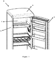
Figure 1 is a front perspective view of a cooling device comprising a panel. -
Figure 2 ; is a bottom perspective view of a cooling device comprising a panel. -
Figure 3 ; is a bottom perspective view of a cooling device comprising the panel group according to the invention. -
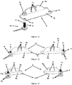
Figure 4 ; is a perspective view of the panel adjustment apparatus according to the invention. -
Figure 5 ; is a front view of an embodiment of the panel adjustment apparatus according to the invention. -
Figure 6 ; is a front view of another embodiment of panel adjustment apparatus according to the invention. -
Figure 7 is a perspective view of a panel of the panel adjustment group according to the invention. -
Figure 8 is a perspective view of the assembly of the developed panel adjustment group to a cooling device. - All the parts illustrated in figures are individually assigned a reference numeral and the corresponding terms of these numbers are listed below:
Cooling device (S) Inner chamber (1) First body (2) Door (3) Panel (4) Channel (5) First surface (6a) Second surface (6b) Hole (7) Bracket (8) Supporting unit (9) Adjustment pin (10) Second body (11) Flange (12) Thread (13) - Cooling devices may comprise an upper panel that is removably mounted on an upper part of the body. However, in refrigerators with an upper panel, an undesired level of opening may occur between the door and the upper panel. In addition, vibration and similar effects to which the cooling device is exposed during transportation may cause the position of the upper panel to change and the opening between the door and the upper panel to increase. Therefore, according to the present invention, there is developed a panel adjustment apparatus for cooling devices, which adjusts panel height and therefore the distance between the panel and the door of the cooling device, a panel group comprising the panel adjustment apparatus and a cooling device comprising the panel group.
- The panel adjustment apparatus according to the present invention, as illustrated in
figures 3-8 , is suitable for use in a cooling device (S), such as a refrigerator, which comprises at least a first body (2) with at least one inner chamber (1); at least one door (3) which is mounted on a front face of the first body (2); at least one panel (4) which is removably mounted on an upper surface of the first body (2) and has at least one channel (5) on a lower surface thereof that faces the first body (2); wherein the panel adjustment apparatus comprises: - at least one bracket (8) having at least a first surface (6a) and at least a second surface (6b) which are connected at a right angle of 90°, at least a first hole (7a) located on the first surface (6a) and at least a second hole (7b) located on the second surface (6b), wherein the bracket (8) is adapted to be mounted on an area of the first body (2) between the door (3) and the panel (4) through the first hole (7a) by means of a connection means such as a screw or the like (not shown in the figures), such that the second surface (6b) thereof extends parallel to the panel (4);
- at least one adjustment pin (10) having at least a second body (11), threads (13) and at least one flange (12), wherein the second body (11) is preferably in the form of a cylinder and is adapted to pass through the second hole (7b) and the channel (5), wherein the threads (13) are located on the second body (11) and allow the second body (11) to move up and down in the second hole (7b) and the channel (5) when the second body (11) is rotated by the user, wherein the flange (12) is located at an end of the second body (11) (at an end of the second body opposite to the end thereof inserted through the second hole (7b) and the channel (5)) and rests against the second surface (6b) so as to prevent second body (11) from moving further in the second hole (7b); and
- at least one supporting unit (9) in the form of a ring, which is preferably made of a flexible material such as sponge, Styrofoam or the like, is adapted to be attached to the second body (11) so as to be located between the second hole (7b) and the channel (5), and maintains the distance between the panel (4) and the door (3).
- In an exemplary embodiment of the invention, while producing the cooling device (S), the door (3) is mounted on the front surface of the first body (2) to control the access into the inner chamber (1) by opening or closing. Moreover, the panel (4) is mounted on the first body (2) in a removable manner, with a lower surface thereof facing the upper surface of the first body (2). The panel (4) comprises the channel (5) located on its lower surface. The bracket (8) of the panel adjustment apparatus according to the invention is mounted on the front surface of the first body (2), in an area between the panel (4) and the door (3). The assembly process can be performed by passing a screw or a similar connection means through the first hole (7a) located on the first surface (6a) and through a mounting hole located on the front surface of the first body (2). When the bracket (8) is mounted such that its first surface (6a) contacts the front surface of the first body (2), the second surface (6b) extends parallel to the panel (4). In this case, the second hole (7b) located on the second surface (6b) and the channel (5) located on the lower surface of the panel (4) are at least partially aligned. The second body (11) of the adjustment pin (10) is positioned such that one end thereof passes through the second hole (7b) and channel (5), and when the second body (11) is rotated by the user, the second body (11) moves up and down in the channel (5) and the second hole (7b) by means of the threads (13) thereof. The flange (12) is located at the other end of the second body (11) opposite to the end inserted through the second hole (7b) and the channel (5), and rests against the second surface (6b) after a certain point, thereby preventing the second body (11) from moving upwards in the second hole (7b). In this case, by rotating the adjustment pin (10) further, the panel (4) is moved downward so as to approach the second surface (6b). Further, the supporting unit (9) is in the form of a ring and is passed through a space in the midsection to the second body (11), wherein the supporting unit (9) is located on the second body (11), between the second hole (7b) and the channel (5). The supporting unit (9) has a flexible structure and ensures that the distance between the panel (4) and the second surface (6b) and therefore the distance between the panel (4) and the door (3) is maintained.
- In a preferred embodiment of the invention, the adjustment pin (10) comprises at least one slit (not shown in the figures) located at the end of the adjustment pin (10) where the flange (12) is provided. In said embodiment, the user can rotate the adjustment pin (10) by using a screwdriver so as to tighten it.
- According to the present invention, there is also provided a panel group comprising the panel adjustment apparatus and the panel having at least one channel (5) on a lower surface thereof. In a preferred embodiment of the invention, the panel (4) comprises at least two channels (5) extending parallel to each other, while the panel adjustment apparatus comprises at least two brackets (8) each adapted to be mounted on the first body (2) so as to be in alignment with the second hole (7b) and the channel (5); at least two adjustments pins (10); and at least two supporting units (9). An example of said embodiment is illustrated in
Figure 8 . - According to the present invention, there is also provided a cooling device (S) comprising said panel group.
- The panel adjustment apparatus according to the invention eliminates undesired opening between the door (3) and the panel (4), which occurs in cooling devices with panels (4), and enables said opening to be adjusted by the bracket (8) and the adjustment pin (10) and to be maintained by the supporting unit (9).
Claims (6)
- A panel adjustment apparatus suitable for use in a cooling device (S) which comprises at least a first body (2) with at least one inner chamber (1); at least one door (3) which is mounted on a front face of the first body (2); at least one panel (4) which is removably mounted on an upper surface of the first body (2) and has at least one channel (5) on a lower surface thereof that faces the first body (2); wherein the panel adjustment apparatus comprises:- at least one bracket (8) having at least a first surface (6a) and at least a second surface (6b) which are connected at a right angle of 90°, at least a first hole (7a) located on the first surface (6a) and at least a second hole (7b) located on the second surface (6b), wherein the bracket (8) is adapted to be mounted on an area of the first body (2) between the door (3) and the panel (4) through the first hole (7a) by means of a connection means;- at least one adjustment pin (10) having at least a second body (11), threads (13) and at least one flange (12), wherein the second body (11) is adapted to pass through the second hole (7b) and the channel (5), wherein the threads (13) are located on the second body (11) and allow the second body (11) to move up and down in the second hole (7b) and the channel (5) when the second body (11) is rotated, wherein the flange (12) is located at an end of the second body (11) and rests against the second surface (6b) so as to prevent second body (11) from moving further in the second hole (7b); and- at least one supporting unit (9) in the form of a ring, which is made of a flexible material, is adapted to be attached to the second body (11) so as to be located between the second hole (7b) and the channel (5), and maintains the distance between the panel (4) and the door (3).
- A panel adjustment apparatus according to claim 1, characterized in that the supporting unit (9) is made of sponge.
- A panel adjustment apparatus according to any of the claims 1 or 2, characterized in that the adjustment pin (10) comprises at least one slit located at the end of the adjustment pin (10) where the flange (12) is provided.
- A panel group comprising a panel adjustment apparatus according to any of the preceding claims and said panel (4).
- A panel group according to claim 4, characterized in that the panel (4) comprises at least two channels (5) extending parallel to each other; and that the panel adjustment apparatus comprises at least two brackets (8); at least two adjustment pins (10); and at least two supporting units (9).
- A cooling device (S) comprising a panel group according to any of the claims 4 or 5.
Applications Claiming Priority (1)
| Application Number | Priority Date | Filing Date | Title |
|---|---|---|---|
| TR2019/21900A TR201921900A2 (en) | 2019-12-27 | 2019-12-27 | A table set including the table setting apparatus, the table setting apparatus and a cooling device. |
Publications (2)
| Publication Number | Publication Date |
|---|---|
| EP3842716A1 true EP3842716A1 (en) | 2021-06-30 |
| EP3842716B1 EP3842716B1 (en) | 2024-01-17 |
Family
ID=74183018
Family Applications (1)
| Application Number | Title | Priority Date | Filing Date |
|---|---|---|---|
| EP20217180.7A Active EP3842716B1 (en) | 2019-12-27 | 2020-12-24 | Cooling device |
Country Status (2)
| Country | Link |
|---|---|
| EP (1) | EP3842716B1 (en) |
| TR (1) | TR201921900A2 (en) |
Citations (4)
| Publication number | Priority date | Publication date | Assignee | Title |
|---|---|---|---|---|
| EP0769667A2 (en) * | 1995-10-19 | 1997-04-23 | AEG Hausgeräte GmbH | Refrigerating and/or freezing apparatus |
| JPH10323249A (en) * | 1997-05-23 | 1998-12-08 | Hoshizaki Electric Co Ltd | Fall preventive device for assembly type box body |
| JP2000342398A (en) * | 1999-06-02 | 2000-12-12 | Sanden Corp | Open showcase |
| US7752709B2 (en) | 2005-04-22 | 2010-07-13 | Lg Electronics Inc. | Refrigerator having height-adjustable door |
-
2019
- 2019-12-27 TR TR2019/21900A patent/TR201921900A2/en unknown
-
2020
- 2020-12-24 EP EP20217180.7A patent/EP3842716B1/en active Active
Patent Citations (4)
| Publication number | Priority date | Publication date | Assignee | Title |
|---|---|---|---|---|
| EP0769667A2 (en) * | 1995-10-19 | 1997-04-23 | AEG Hausgeräte GmbH | Refrigerating and/or freezing apparatus |
| JPH10323249A (en) * | 1997-05-23 | 1998-12-08 | Hoshizaki Electric Co Ltd | Fall preventive device for assembly type box body |
| JP2000342398A (en) * | 1999-06-02 | 2000-12-12 | Sanden Corp | Open showcase |
| US7752709B2 (en) | 2005-04-22 | 2010-07-13 | Lg Electronics Inc. | Refrigerator having height-adjustable door |
Also Published As
| Publication number | Publication date |
|---|---|
| EP3842716B1 (en) | 2024-01-17 |
| TR201921900A2 (en) | 2021-07-26 |
Similar Documents
| Publication | Publication Date | Title |
|---|---|---|
| TWI739205B (en) | A guide system for guiding at least one movablysupported door wing, urniture with the guide system, and method for assembling at least one door leaf on the guide system | |
| US7752709B2 (en) | Refrigerator having height-adjustable door | |
| US9206641B2 (en) | Adjustable roller shade mounting bracket | |
| US20030093877A1 (en) | Hinge for furniture | |
| US9549643B2 (en) | Adjustable curved door assembly | |
| EP2573491A2 (en) | Refrigerator | |
| CN108868419B (en) | Movable plate support with adjusting auxiliary part | |
| US6684457B2 (en) | Adjustable and reversible hinge assembly | |
| US20150008813A1 (en) | Top mount adjustable cabinet mounted frame | |
| US4842422A (en) | Eccentric adjuster for drawer or cabinet track | |
| US5121976A (en) | Furniture article with a door slidable into door compartment | |
| EP3842716B1 (en) | Cooling device | |
| US11445821B2 (en) | Lazy susan fitting for a corner cabinet | |
| CN1959049B (en) | Safety device against false manoeuvres for sliding window and door frames | |
| JP2021022584A (en) | Rotating door mounting position adjustment mechanism, rotating door device, and image forming device | |
| KR200338112Y1 (en) | Lower hinge assembly for door of refrigerator | |
| US6079164A (en) | Device for connecting two panels together and for adjusting their spatial arrangement | |
| CN101131279A (en) | Hinge device used for regulating height of refrigerator door | |
| KR100262397B1 (en) | Refrigerator door height adjustment | |
| KR100675777B1 (en) | Vertical hinge hinge device of refrigerator door | |
| KR20230144240A (en) | Mortise Apparatus for Door-Lock | |
| CN107939198B (en) | Air supporting structure | |
| EP3411644B1 (en) | Adjustable hinge assembly for use in a refrigerator | |
| EP3884226B1 (en) | A cooling device comprising a position-adjustable door | |
| CN222881483U (en) | Grille assembly and refrigeration equipment |
Legal Events
| Date | Code | Title | Description |
|---|---|---|---|
| PUAI | Public reference made under article 153(3) epc to a published international application that has entered the european phase |
Free format text: ORIGINAL CODE: 0009012 |
|
| STAA | Information on the status of an ep patent application or granted ep patent |
Free format text: STATUS: THE APPLICATION HAS BEEN PUBLISHED |
|
| AK | Designated contracting states |
Kind code of ref document: A1 Designated state(s): AL AT BE BG CH CY CZ DE DK EE ES FI FR GB GR HR HU IE IS IT LI LT LU LV MC MK MT NL NO PL PT RO RS SE SI SK SM TR |
|
| STAA | Information on the status of an ep patent application or granted ep patent |
Free format text: STATUS: REQUEST FOR EXAMINATION WAS MADE |
|
| 17P | Request for examination filed |
Effective date: 20211221 |
|
| RBV | Designated contracting states (corrected) |
Designated state(s): AL AT BE BG CH CY CZ DE DK EE ES FI FR GB GR HR HU IE IS IT LI LT LU LV MC MK MT NL NO PL PT RO RS SE SI SK SM TR |
|
| GRAP | Despatch of communication of intention to grant a patent |
Free format text: ORIGINAL CODE: EPIDOSNIGR1 |
|
| STAA | Information on the status of an ep patent application or granted ep patent |
Free format text: STATUS: GRANT OF PATENT IS INTENDED |
|
| RIC1 | Information provided on ipc code assigned before grant |
Ipc: F25D 23/06 20060101AFI20230727BHEP |
|
| INTG | Intention to grant announced |
Effective date: 20230811 |
|
| GRAS | Grant fee paid |
Free format text: ORIGINAL CODE: EPIDOSNIGR3 |
|
| GRAA | (expected) grant |
Free format text: ORIGINAL CODE: 0009210 |
|
| STAA | Information on the status of an ep patent application or granted ep patent |
Free format text: STATUS: THE PATENT HAS BEEN GRANTED |
|
| AK | Designated contracting states |
Kind code of ref document: B1 Designated state(s): AL AT BE BG CH CY CZ DE DK EE ES FI FR GB GR HR HU IE IS IT LI LT LU LV MC MK MT NL NO PL PT RO RS SE SI SK SM TR |
|
| REG | Reference to a national code |
Ref country code: GB Ref legal event code: FG4D |
|
| REG | Reference to a national code |
Ref country code: CH Ref legal event code: EP |
|
| REG | Reference to a national code |
Ref country code: DE Ref legal event code: R096 Ref document number: 602020024449 Country of ref document: DE |
|
| REG | Reference to a national code |
Ref country code: IE Ref legal event code: FG4D |
|
| REG | Reference to a national code |
Ref country code: LT Ref legal event code: MG9D |
|
| REG | Reference to a national code |
Ref country code: NL Ref legal event code: MP Effective date: 20240117 |
|
| REG | Reference to a national code |
Ref country code: AT Ref legal event code: MK05 Ref document number: 1650780 Country of ref document: AT Kind code of ref document: T Effective date: 20240117 |
|
| PG25 | Lapsed in a contracting state [announced via postgrant information from national office to epo] |
Ref country code: NL Free format text: LAPSE BECAUSE OF FAILURE TO SUBMIT A TRANSLATION OF THE DESCRIPTION OR TO PAY THE FEE WITHIN THE PRESCRIBED TIME-LIMIT Effective date: 20240117 |
|
| PG25 | Lapsed in a contracting state [announced via postgrant information from national office to epo] |
Ref country code: NL Free format text: LAPSE BECAUSE OF FAILURE TO SUBMIT A TRANSLATION OF THE DESCRIPTION OR TO PAY THE FEE WITHIN THE PRESCRIBED TIME-LIMIT Effective date: 20240117 |
|
| PG25 | Lapsed in a contracting state [announced via postgrant information from national office to epo] |
Ref country code: IS Free format text: LAPSE BECAUSE OF FAILURE TO SUBMIT A TRANSLATION OF THE DESCRIPTION OR TO PAY THE FEE WITHIN THE PRESCRIBED TIME-LIMIT Effective date: 20240517 |
|
| PG25 | Lapsed in a contracting state [announced via postgrant information from national office to epo] |
Ref country code: LT Free format text: LAPSE BECAUSE OF FAILURE TO SUBMIT A TRANSLATION OF THE DESCRIPTION OR TO PAY THE FEE WITHIN THE PRESCRIBED TIME-LIMIT Effective date: 20240117 |
|
| PG25 | Lapsed in a contracting state [announced via postgrant information from national office to epo] |
Ref country code: GR Free format text: LAPSE BECAUSE OF FAILURE TO SUBMIT A TRANSLATION OF THE DESCRIPTION OR TO PAY THE FEE WITHIN THE PRESCRIBED TIME-LIMIT Effective date: 20240418 |
|
| PG25 | Lapsed in a contracting state [announced via postgrant information from national office to epo] |
Ref country code: HR Free format text: LAPSE BECAUSE OF FAILURE TO SUBMIT A TRANSLATION OF THE DESCRIPTION OR TO PAY THE FEE WITHIN THE PRESCRIBED TIME-LIMIT Effective date: 20240117 Ref country code: RS Free format text: LAPSE BECAUSE OF FAILURE TO SUBMIT A TRANSLATION OF THE DESCRIPTION OR TO PAY THE FEE WITHIN THE PRESCRIBED TIME-LIMIT Effective date: 20240417 |
|
| PG25 | Lapsed in a contracting state [announced via postgrant information from national office to epo] |
Ref country code: ES Free format text: LAPSE BECAUSE OF FAILURE TO SUBMIT A TRANSLATION OF THE DESCRIPTION OR TO PAY THE FEE WITHIN THE PRESCRIBED TIME-LIMIT Effective date: 20240117 |
|
| PG25 | Lapsed in a contracting state [announced via postgrant information from national office to epo] |
Ref country code: AT Free format text: LAPSE BECAUSE OF FAILURE TO SUBMIT A TRANSLATION OF THE DESCRIPTION OR TO PAY THE FEE WITHIN THE PRESCRIBED TIME-LIMIT Effective date: 20240117 |
|
| PG25 | Lapsed in a contracting state [announced via postgrant information from national office to epo] |
Ref country code: RS Free format text: LAPSE BECAUSE OF FAILURE TO SUBMIT A TRANSLATION OF THE DESCRIPTION OR TO PAY THE FEE WITHIN THE PRESCRIBED TIME-LIMIT Effective date: 20240417 Ref country code: NO Free format text: LAPSE BECAUSE OF FAILURE TO SUBMIT A TRANSLATION OF THE DESCRIPTION OR TO PAY THE FEE WITHIN THE PRESCRIBED TIME-LIMIT Effective date: 20240417 Ref country code: LT Free format text: LAPSE BECAUSE OF FAILURE TO SUBMIT A TRANSLATION OF THE DESCRIPTION OR TO PAY THE FEE WITHIN THE PRESCRIBED TIME-LIMIT Effective date: 20240117 Ref country code: IS Free format text: LAPSE BECAUSE OF FAILURE TO SUBMIT A TRANSLATION OF THE DESCRIPTION OR TO PAY THE FEE WITHIN THE PRESCRIBED TIME-LIMIT Effective date: 20240517 Ref country code: HR Free format text: LAPSE BECAUSE OF FAILURE TO SUBMIT A TRANSLATION OF THE DESCRIPTION OR TO PAY THE FEE WITHIN THE PRESCRIBED TIME-LIMIT Effective date: 20240117 Ref country code: GR Free format text: LAPSE BECAUSE OF FAILURE TO SUBMIT A TRANSLATION OF THE DESCRIPTION OR TO PAY THE FEE WITHIN THE PRESCRIBED TIME-LIMIT Effective date: 20240418 Ref country code: FI Free format text: LAPSE BECAUSE OF FAILURE TO SUBMIT A TRANSLATION OF THE DESCRIPTION OR TO PAY THE FEE WITHIN THE PRESCRIBED TIME-LIMIT Effective date: 20240117 Ref country code: ES Free format text: LAPSE BECAUSE OF FAILURE TO SUBMIT A TRANSLATION OF THE DESCRIPTION OR TO PAY THE FEE WITHIN THE PRESCRIBED TIME-LIMIT Effective date: 20240117 Ref country code: BG Free format text: LAPSE BECAUSE OF FAILURE TO SUBMIT A TRANSLATION OF THE DESCRIPTION OR TO PAY THE FEE WITHIN THE PRESCRIBED TIME-LIMIT Effective date: 20240117 Ref country code: AT Free format text: LAPSE BECAUSE OF FAILURE TO SUBMIT A TRANSLATION OF THE DESCRIPTION OR TO PAY THE FEE WITHIN THE PRESCRIBED TIME-LIMIT Effective date: 20240117 |
|
| PG25 | Lapsed in a contracting state [announced via postgrant information from national office to epo] |
Ref country code: PT Free format text: LAPSE BECAUSE OF FAILURE TO SUBMIT A TRANSLATION OF THE DESCRIPTION OR TO PAY THE FEE WITHIN THE PRESCRIBED TIME-LIMIT Effective date: 20240517 Ref country code: PL Free format text: LAPSE BECAUSE OF FAILURE TO SUBMIT A TRANSLATION OF THE DESCRIPTION OR TO PAY THE FEE WITHIN THE PRESCRIBED TIME-LIMIT Effective date: 20240117 |
|
| PG25 | Lapsed in a contracting state [announced via postgrant information from national office to epo] |
Ref country code: SE Free format text: LAPSE BECAUSE OF FAILURE TO SUBMIT A TRANSLATION OF THE DESCRIPTION OR TO PAY THE FEE WITHIN THE PRESCRIBED TIME-LIMIT Effective date: 20240117 Ref country code: PT Free format text: LAPSE BECAUSE OF FAILURE TO SUBMIT A TRANSLATION OF THE DESCRIPTION OR TO PAY THE FEE WITHIN THE PRESCRIBED TIME-LIMIT Effective date: 20240517 Ref country code: PL Free format text: LAPSE BECAUSE OF FAILURE TO SUBMIT A TRANSLATION OF THE DESCRIPTION OR TO PAY THE FEE WITHIN THE PRESCRIBED TIME-LIMIT Effective date: 20240117 Ref country code: LV Free format text: LAPSE BECAUSE OF FAILURE TO SUBMIT A TRANSLATION OF THE DESCRIPTION OR TO PAY THE FEE WITHIN THE PRESCRIBED TIME-LIMIT Effective date: 20240117 |
|
| PG25 | Lapsed in a contracting state [announced via postgrant information from national office to epo] |
Ref country code: DK Free format text: LAPSE BECAUSE OF FAILURE TO SUBMIT A TRANSLATION OF THE DESCRIPTION OR TO PAY THE FEE WITHIN THE PRESCRIBED TIME-LIMIT Effective date: 20240117 |
|
| PG25 | Lapsed in a contracting state [announced via postgrant information from national office to epo] |
Ref country code: SM Free format text: LAPSE BECAUSE OF FAILURE TO SUBMIT A TRANSLATION OF THE DESCRIPTION OR TO PAY THE FEE WITHIN THE PRESCRIBED TIME-LIMIT Effective date: 20240117 |
|
| REG | Reference to a national code |
Ref country code: DE Ref legal event code: R097 Ref document number: 602020024449 Country of ref document: DE |
|
| PG25 | Lapsed in a contracting state [announced via postgrant information from national office to epo] |
Ref country code: EE Free format text: LAPSE BECAUSE OF FAILURE TO SUBMIT A TRANSLATION OF THE DESCRIPTION OR TO PAY THE FEE WITHIN THE PRESCRIBED TIME-LIMIT Effective date: 20240117 Ref country code: CZ Free format text: LAPSE BECAUSE OF FAILURE TO SUBMIT A TRANSLATION OF THE DESCRIPTION OR TO PAY THE FEE WITHIN THE PRESCRIBED TIME-LIMIT Effective date: 20240117 |
|
| PG25 | Lapsed in a contracting state [announced via postgrant information from national office to epo] |
Ref country code: SK Free format text: LAPSE BECAUSE OF FAILURE TO SUBMIT A TRANSLATION OF THE DESCRIPTION OR TO PAY THE FEE WITHIN THE PRESCRIBED TIME-LIMIT Effective date: 20240117 |
|
| PG25 | Lapsed in a contracting state [announced via postgrant information from national office to epo] |
Ref country code: SM Free format text: LAPSE BECAUSE OF FAILURE TO SUBMIT A TRANSLATION OF THE DESCRIPTION OR TO PAY THE FEE WITHIN THE PRESCRIBED TIME-LIMIT Effective date: 20240117 Ref country code: SK Free format text: LAPSE BECAUSE OF FAILURE TO SUBMIT A TRANSLATION OF THE DESCRIPTION OR TO PAY THE FEE WITHIN THE PRESCRIBED TIME-LIMIT Effective date: 20240117 Ref country code: RO Free format text: LAPSE BECAUSE OF FAILURE TO SUBMIT A TRANSLATION OF THE DESCRIPTION OR TO PAY THE FEE WITHIN THE PRESCRIBED TIME-LIMIT Effective date: 20240117 Ref country code: EE Free format text: LAPSE BECAUSE OF FAILURE TO SUBMIT A TRANSLATION OF THE DESCRIPTION OR TO PAY THE FEE WITHIN THE PRESCRIBED TIME-LIMIT Effective date: 20240117 Ref country code: DK Free format text: LAPSE BECAUSE OF FAILURE TO SUBMIT A TRANSLATION OF THE DESCRIPTION OR TO PAY THE FEE WITHIN THE PRESCRIBED TIME-LIMIT Effective date: 20240117 Ref country code: CZ Free format text: LAPSE BECAUSE OF FAILURE TO SUBMIT A TRANSLATION OF THE DESCRIPTION OR TO PAY THE FEE WITHIN THE PRESCRIBED TIME-LIMIT Effective date: 20240117 |
|
| PLBE | No opposition filed within time limit |
Free format text: ORIGINAL CODE: 0009261 |
|
| STAA | Information on the status of an ep patent application or granted ep patent |
Free format text: STATUS: NO OPPOSITION FILED WITHIN TIME LIMIT |
|
| 26N | No opposition filed |
Effective date: 20241018 |
|
| PG25 | Lapsed in a contracting state [announced via postgrant information from national office to epo] |
Ref country code: SI Free format text: LAPSE BECAUSE OF FAILURE TO SUBMIT A TRANSLATION OF THE DESCRIPTION OR TO PAY THE FEE WITHIN THE PRESCRIBED TIME-LIMIT Effective date: 20240117 |
|
| PG25 | Lapsed in a contracting state [announced via postgrant information from national office to epo] |
Ref country code: MC Free format text: LAPSE BECAUSE OF FAILURE TO SUBMIT A TRANSLATION OF THE DESCRIPTION OR TO PAY THE FEE WITHIN THE PRESCRIBED TIME-LIMIT Effective date: 20240117 |
|
| REG | Reference to a national code |
Ref country code: CH Ref legal event code: PL |
|
| PG25 | Lapsed in a contracting state [announced via postgrant information from national office to epo] |
Ref country code: LU Free format text: LAPSE BECAUSE OF NON-PAYMENT OF DUE FEES Effective date: 20241224 |
|
| GBPC | Gb: european patent ceased through non-payment of renewal fee |
Effective date: 20241224 |
|
| REG | Reference to a national code |
Ref country code: BE Ref legal event code: MM Effective date: 20241231 |
|
| PG25 | Lapsed in a contracting state [announced via postgrant information from national office to epo] |
Ref country code: GB Free format text: LAPSE BECAUSE OF NON-PAYMENT OF DUE FEES Effective date: 20241224 Ref country code: BE Free format text: LAPSE BECAUSE OF NON-PAYMENT OF DUE FEES Effective date: 20241231 |
|
| PG25 | Lapsed in a contracting state [announced via postgrant information from national office to epo] |
Ref country code: FR Free format text: LAPSE BECAUSE OF NON-PAYMENT OF DUE FEES Effective date: 20241231 |
|
| PG25 | Lapsed in a contracting state [announced via postgrant information from national office to epo] |
Ref country code: CH Free format text: LAPSE BECAUSE OF NON-PAYMENT OF DUE FEES Effective date: 20241231 |
|
| PG25 | Lapsed in a contracting state [announced via postgrant information from national office to epo] |
Ref country code: IE Free format text: LAPSE BECAUSE OF NON-PAYMENT OF DUE FEES Effective date: 20241224 |
|
| PGFP | Annual fee paid to national office [announced via postgrant information from national office to epo] |
Ref country code: DE Payment date: 20251211 Year of fee payment: 6 |
|
| PGFP | Annual fee paid to national office [announced via postgrant information from national office to epo] |
Ref country code: IT Payment date: 20251223 Year of fee payment: 6 |
|
| PGFP | Annual fee paid to national office [announced via postgrant information from national office to epo] |
Ref country code: TR Payment date: 20251219 Year of fee payment: 6 |