EP3842624B1 - Method and system for determining sulfur poisoning state of selectively catalytic reduction device - Google Patents
Method and system for determining sulfur poisoning state of selectively catalytic reduction device Download PDFInfo
- Publication number
- EP3842624B1 EP3842624B1 EP20196612.4A EP20196612A EP3842624B1 EP 3842624 B1 EP3842624 B1 EP 3842624B1 EP 20196612 A EP20196612 A EP 20196612A EP 3842624 B1 EP3842624 B1 EP 3842624B1
- Authority
- EP
- European Patent Office
- Prior art keywords
- scr device
- predetermined
- efficiency
- determining
- value
- Prior art date
- Legal status (The legal status is an assumption and is not a legal conclusion. Google has not performed a legal analysis and makes no representation as to the accuracy of the status listed.)
- Active
Links
Images



Classifications
-
- F—MECHANICAL ENGINEERING; LIGHTING; HEATING; WEAPONS; BLASTING
- F01—MACHINES OR ENGINES IN GENERAL; ENGINE PLANTS IN GENERAL; STEAM ENGINES
- F01N—GAS-FLOW SILENCERS OR EXHAUST APPARATUS FOR MACHINES OR ENGINES IN GENERAL; GAS-FLOW SILENCERS OR EXHAUST APPARATUS FOR INTERNAL-COMBUSTION ENGINES
- F01N11/00—Monitoring or diagnostic devices for exhaust-gas treatment apparatus
-
- F—MECHANICAL ENGINEERING; LIGHTING; HEATING; WEAPONS; BLASTING
- F01—MACHINES OR ENGINES IN GENERAL; ENGINE PLANTS IN GENERAL; STEAM ENGINES
- F01N—GAS-FLOW SILENCERS OR EXHAUST APPARATUS FOR MACHINES OR ENGINES IN GENERAL; GAS-FLOW SILENCERS OR EXHAUST APPARATUS FOR INTERNAL-COMBUSTION ENGINES
- F01N3/00—Exhaust or silencing apparatus having means for purifying, rendering innocuous, or otherwise treating exhaust
- F01N3/08—Exhaust or silencing apparatus having means for purifying, rendering innocuous, or otherwise treating exhaust for rendering innocuous
- F01N3/10—Exhaust or silencing apparatus having means for purifying, rendering innocuous, or otherwise treating exhaust for rendering innocuous by thermal or catalytic conversion of noxious components of exhaust
- F01N3/18—Exhaust or silencing apparatus having means for purifying, rendering innocuous, or otherwise treating exhaust for rendering innocuous by thermal or catalytic conversion of noxious components of exhaust characterised by methods of operation; Control
- F01N3/20—Exhaust or silencing apparatus having means for purifying, rendering innocuous, or otherwise treating exhaust for rendering innocuous by thermal or catalytic conversion of noxious components of exhaust characterised by methods of operation; Control specially adapted for catalytic conversion
- F01N3/206—Adding periodically or continuously substances to exhaust gases for promoting purification, e.g. catalytic material in liquid form, NOx reducing agents
- F01N3/2066—Selective catalytic reduction [SCR]
-
- F—MECHANICAL ENGINEERING; LIGHTING; HEATING; WEAPONS; BLASTING
- F01—MACHINES OR ENGINES IN GENERAL; ENGINE PLANTS IN GENERAL; STEAM ENGINES
- F01N—GAS-FLOW SILENCERS OR EXHAUST APPARATUS FOR MACHINES OR ENGINES IN GENERAL; GAS-FLOW SILENCERS OR EXHAUST APPARATUS FOR INTERNAL-COMBUSTION ENGINES
- F01N3/00—Exhaust or silencing apparatus having means for purifying, rendering innocuous, or otherwise treating exhaust
- F01N3/08—Exhaust or silencing apparatus having means for purifying, rendering innocuous, or otherwise treating exhaust for rendering innocuous
- F01N3/10—Exhaust or silencing apparatus having means for purifying, rendering innocuous, or otherwise treating exhaust for rendering innocuous by thermal or catalytic conversion of noxious components of exhaust
- F01N3/18—Exhaust or silencing apparatus having means for purifying, rendering innocuous, or otherwise treating exhaust for rendering innocuous by thermal or catalytic conversion of noxious components of exhaust characterised by methods of operation; Control
- F01N3/20—Exhaust or silencing apparatus having means for purifying, rendering innocuous, or otherwise treating exhaust for rendering innocuous by thermal or catalytic conversion of noxious components of exhaust characterised by methods of operation; Control specially adapted for catalytic conversion
- F01N3/206—Adding periodically or continuously substances to exhaust gases for promoting purification, e.g. catalytic material in liquid form, NOx reducing agents
- F01N3/208—Control of selective catalytic reduction [SCR], e.g. by adjusting the dosing of reducing agent
-
- F—MECHANICAL ENGINEERING; LIGHTING; HEATING; WEAPONS; BLASTING
- F01—MACHINES OR ENGINES IN GENERAL; ENGINE PLANTS IN GENERAL; STEAM ENGINES
- F01N—GAS-FLOW SILENCERS OR EXHAUST APPARATUS FOR MACHINES OR ENGINES IN GENERAL; GAS-FLOW SILENCERS OR EXHAUST APPARATUS FOR INTERNAL-COMBUSTION ENGINES
- F01N2550/00—Monitoring or diagnosing the deterioration of exhaust systems
- F01N2550/02—Catalytic activity of catalytic converters
-
- F—MECHANICAL ENGINEERING; LIGHTING; HEATING; WEAPONS; BLASTING
- F01—MACHINES OR ENGINES IN GENERAL; ENGINE PLANTS IN GENERAL; STEAM ENGINES
- F01N—GAS-FLOW SILENCERS OR EXHAUST APPARATUS FOR MACHINES OR ENGINES IN GENERAL; GAS-FLOW SILENCERS OR EXHAUST APPARATUS FOR INTERNAL-COMBUSTION ENGINES
- F01N2570/00—Exhaust treating apparatus eliminating, absorbing or adsorbing specific elements or compounds
- F01N2570/04—Sulfur or sulfur oxides
-
- F—MECHANICAL ENGINEERING; LIGHTING; HEATING; WEAPONS; BLASTING
- F01—MACHINES OR ENGINES IN GENERAL; ENGINE PLANTS IN GENERAL; STEAM ENGINES
- F01N—GAS-FLOW SILENCERS OR EXHAUST APPARATUS FOR MACHINES OR ENGINES IN GENERAL; GAS-FLOW SILENCERS OR EXHAUST APPARATUS FOR INTERNAL-COMBUSTION ENGINES
- F01N2610/00—Adding substances to exhaust gases
- F01N2610/02—Adding substances to exhaust gases the substance being ammonia or urea
-
- F—MECHANICAL ENGINEERING; LIGHTING; HEATING; WEAPONS; BLASTING
- F01—MACHINES OR ENGINES IN GENERAL; ENGINE PLANTS IN GENERAL; STEAM ENGINES
- F01N—GAS-FLOW SILENCERS OR EXHAUST APPARATUS FOR MACHINES OR ENGINES IN GENERAL; GAS-FLOW SILENCERS OR EXHAUST APPARATUS FOR INTERNAL-COMBUSTION ENGINES
- F01N2900/00—Details of electrical control or of the monitoring of the exhaust gas treating apparatus
- F01N2900/06—Parameters used for exhaust control or diagnosing
- F01N2900/16—Parameters used for exhaust control or diagnosing said parameters being related to the exhaust apparatus, e.g. particulate filter or catalyst
- F01N2900/1612—SOx amount trapped in catalyst
-
- F—MECHANICAL ENGINEERING; LIGHTING; HEATING; WEAPONS; BLASTING
- F01—MACHINES OR ENGINES IN GENERAL; ENGINE PLANTS IN GENERAL; STEAM ENGINES
- F01N—GAS-FLOW SILENCERS OR EXHAUST APPARATUS FOR MACHINES OR ENGINES IN GENERAL; GAS-FLOW SILENCERS OR EXHAUST APPARATUS FOR INTERNAL-COMBUSTION ENGINES
- F01N2900/00—Details of electrical control or of the monitoring of the exhaust gas treating apparatus
- F01N2900/06—Parameters used for exhaust control or diagnosing
- F01N2900/16—Parameters used for exhaust control or diagnosing said parameters being related to the exhaust apparatus, e.g. particulate filter or catalyst
- F01N2900/1621—Catalyst conversion efficiency
Definitions
- the present disclosure relates to the technical field of vehicle post-treatment, and in particular to a method and a system for determining a sulfur poisoning state of a SCR device.
- a selective catalytic reduction (SCR) device is used to perform treatment for processing nitrogen oxides (NOx) in diesel vehicle exhaust gas, which is to inject reducing agent of ammonia or urea to reduce the NOx in the exhaust gas into nitrogen and water under the action of catalyst.
- NOx nitrogen oxides
- the copper based SCR which has a good low-temperature performance, is widely used in SCR systems in the current market.
- the copper based SCR may have a serious sulfur poisoning problem, which may seriously decrease the efficiency of reducing NOx. Therefore, in practices, it is required to monitor the sulfur poisoning state of the copper based SCR and perform desulfurization regularly.
- a method and a system for determining a sulfur poisoning state of an SCR device are provided according to the present disclosure to realize the purpose of improving the accuracy of determining a sulfur poisoning state of a SCR device.
- a method for determining a sulfur poisoning state of a selective catalytic reduction (SCR) device of a vehicle post-treatment system includes the SCR device and a urea injector. The method includes:
- the determining whether the SCR device and the urea injector meet a predetermined triggering condition includes: monitoring a reduction efficiency of the SCR device in a first predetermined temperature range and a concentration of urea in the urea injector; and determining that the SCR device and the urea injector meet the predetermined triggering condition when the reduction efficiency of the SCR device in the first predetermined temperature range is less than a second predetermined efficiency and the concentration of urea is in a predetermined concentration range.
- the monitoring a low-temperature efficiency of the SCR device includes:
- the calculating accumulated consumption amount of stored ammonia for a first predetermined time period after the urea injection is stopped includes:
- the predetermined concentration range is 32.5% ⁇ 2.5%.
- the method further includes sending a stationary regeneration request.
- the consumption limit value is determined according to an aging factor and an average temperature of the SCR device.
- a system for determining a sulfur poisoning state of a selective catalytic reduction (SCR) device of a vehicle post-treatment system where the vehicle post-treatment system includes the SCR device and a urea injector, and the system for determining the sulfur poisoning state includes:
- the ammonia storage determination module is configured to:
- the predetermined concentration range is 32.5% ⁇ 2.5%.
- the low-temperature efficiency monitoring module is further configured to send a stationary regeneration request after determining that the SCR device is in the sulfur poisoning state.
- the consumption limit value is determined according to an aging factor and an average temperature of the SCR device.
- the method and the system for determining a sulfur poisoning state of a SCR device are provided according to the embodiments of the present disclosure.
- the ammonia storage capacity is detected.
- the urea injection is stopped and the accumulated consumption amount of stored ammonia is calculated. If the accumulated consumption amount of stored ammonia is greater than the consumption limit value, it is determined that there is large ammonia storage. Therefore the subsequent detection is not performed, and the process of sulfur poisoning determination ends.
- the accumulated consumption amount of stored ammonia is less than or equal to the consumption limit value, since the ammonia storage of the SCR is continuously consumed by NOx in upstream gas of SCR, and the first actual reduction efficiency of the SCR device will be gradually decreased.
- the accumulated consumption amount of stored ammonia is less than or equal to the consumption limit value and the first actual reduction efficiency of the SCR device is less than the first predetermined efficiency value, it is determined that ammonia is not leaked, and the problem of low reduction efficiency of the SCR device may be caused by sulfur poisoning or insufficient ammonia storage. In this case, the low-temperature efficiency of the SCR is required to be monitored.
- the difference value between the theoretical reduction efficiency of the SCR device and the second actual reduction efficiency is greater than the difference threshold value, it is determined that the SCR device is in the sulfur poisoning state. It can be seen from the above process, whether the SCR device is in the sulfur poisoning state can be accurately determined by the method without being effected by other facts such as ammonia leakage, aging, ammonia storage control accuracy.
- a method for determining a sulfur poisoning state of a SCR device is provided according to an embodiment of the present disclosure.
- the method is used for determining whether an SCR device of a vehicle post-treatment system is in a sulfur poisoning state.
- the post-treatment system includes the SCR device and a urea injector.
- the method for determining a sulfur poisoning state of a SCR device includes the following steps S101 and S102.
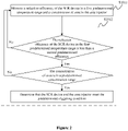
- step S101 it is determined whether the SCR device and the urea injector meet a predetermined triggering condition. If it is determined that the SCR device and the urea injector meet the predetermined triggering condition, the urea injector is controlled to stop urea injection, A first actual reduction efficiency of the SCR device is detected after the urea injection is stopped, and accumulated consumption amount of stored ammonia for a first predetermined time period after the urea injection is stopped is calculated.
- step S102 it is determined whether the first actual reduction efficiency of the SCR device is less than a first predetermined efficiency value, and whether the accumulated consumption amount of stored ammonia is less than or equal to a consumption limit value. If it is determined that the first actual reduction efficiency of the SCR device is less than the first predetermined efficiency value, and the accumulated consumption amount of stored ammonia is less than or equal to the consumption limit value, a low-temperature efficiency of the SCR is monitored, else the process returns to step of determining whether the SCR and urea injector meet the predetermined triggering condition.
- the process of determining whether the SCR device and the urea injector meet the predetermined triggering condition includes steps S1011 and S1012.
- step S1011 a reduction efficiency of the SCR device in a first predetermined temperature range and a concentration of urea in the urea injector are monitored.
- step S1012 when the reduction efficiency of the SCR device in the first predetermined temperature range is less than a second predetermined efficiency, and the concentration of urea is in a predetermined concentration range, it is determined that the SCR device and the urea injector meet the predetermined triggering condition.
- the process of monitoring the low-temperature efficiency of the SCR device includes steps S1021 to S1023.
- step S1021 the urea injector is controlled to perform urea injection with a fixed ammonia-nitrogen mole ratio.
- step S1022 the second actual reduction efficiency of the SCR device for a second predetermined temperature range is monitored.
- step S1023 in a state that the second actual reduction efficiency of the SCR device, an ammonia storage setting value and an ammonia storage value calculated by an ammonia storage model are all stable, it is determined whether a difference value between a theoretical reduction efficiency of the SCR device and the second actual reduction efficiency is greater than a difference threshold value, and if the difference value between the theoretical reduction efficiency of the SCR device and the second actual reduction efficiency is greater than the difference threshold value, it is determined that the SCR device is in the sulfur poisoning state.
- the ammonia storage setting value is determined by searching an ammonia storage mapping table according to a current space velocity and a current average temperature.
- the ammonia storage mapping table stores a correspondence between the space velocity, the average temperature and the ammonia storage setting value.
- the average temperature of the SCR device refers to an average temperature of various parts of the SCR device at a same time. Since the SCR material has a relatively large specific heat capacity, the temperature at an outlet of the SCR device may be changed later than a change in the temperature at an inlet of the SCR device. Therefore, the average temperature of various parts in the SCR device is taken as the average temperature of the SCR device.
- the ammonia storage value calculated by the ammonia storage model is calculated according to a one-dimensional physical model of the SCR device.
- the ammonia storage, an internal temperature, a NOx concentration in downstream gas of the SCR device and other state parameters are calculated by the model in real time according to NOx quantity in upstream gas of the SCR device, exhaust gas volume, urea injection amount, temperature and other conditions.
- the theoretical reduction efficiency of the SCR device is calculated by using the one-dimensional physical model of the SCR device, which is equal to one minus a ratio of a NOx value in downstream gas of the SCR model to a NOx value in upstream gas of the SCR model.
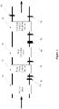
- FIG 4 is a schematic structural diagram of a vehicle post-treatment system.
- the post-treatment system includes a turbocharger (TC), a hydrocarbon (HC) injector, a urea injector, a diesel oxide catalyst (DOC) device, a diesel particulate filter (DPF), a selectively catalytic reduction (SCR) device, and multiple temperature sensors and NOx sensors.
- the urea injector is arranged with a high-precision urea concentration sensor to accurately detect the urea concentration.
- reference sign 10 represents the turbocharger
- reference sign 20 represents the diesel oxide catalyst device
- reference sign 30 represents the diesel particulate filter
- reference sign 40 represents the selectively catalytic reduction device
- reference sign 50 represents the NOx sensors
- reference sign 60 represents the urea injector
- reference sign 70 represents the temperature sensor.
- the direction of the arrow indicates the direction of vehicle exhaust emission.
- the upstream gas of the SCR device refers to the vehicle exhaust inputted into the SCR device
- the downstream gas of the SCR device refers to the vehicle exhaust outputted from the SCR device (as the direction indicated by the arrow).
- the predetermined triggering condition involves SCR low-temperature efficiency monitoring and urea concentration monitoring.
- the SCR low-temperature efficiency monitoring is to monitor the reduction efficiency of the SCR device in a first predetermined temperature range, and determine whether the reduction efficiency of the SCR device in the first predetermined temperature range is less than a second predetermined efficiency. If the reduction efficiency of the SCR device in the first predetermined temperature range is less than the second predetermined efficiency, it is determined that the SCR device meets the predetermined triggering condition.
- the first predetermined temperature range may be determined according to the type of the SCR.
- the first predetermined temperature range may be a range of 220 Celsius degree to 260 Celsius degree.
- the monitoring of the urea concentration range is to determine whether the concentration of urea in the urea injector is in a predetermined concentration range. If the concentration of urea is in a predetermined concentration range, it is determined that the urea injector meets the predetermined triggering condition.
- the predetermined concentration range may be 32.5% ⁇ 2.5%.
- the urea injector In the detection of ammonia storage capacity, the urea injector is controlled to stop urea injection, the first actual reduction efficiency of the SCR device after the urea injection is stopped is detected, and the accumulated consumption amount of stored ammonia for the first predetermined time period after the urea injection is stopped is calculated.
- the process returns to the step of determining whether the SCR device and the urea injector meet the predetermined triggering condition.
- the first actual reduction efficiency of the SCR device will be gradually decreased.
- the first actual reduction efficiency of the SCR device is less than the first predetermined efficiency, and the accumulated consumption amount of stored ammonia is less than or equal to the consumption limit value, it is determined that the ammonia is not leaked and the low efficiency may be caused by sulfur poisoning or insufficient ammonia storage. In this case, the SCR low-temperature efficiency monitoring is performed.
- the predetermined efficiency value may be 0.5, 0.55 and 0.45, but is not limited thereto.
- the consumption limit value is determined according to an SCR aging factor and the average temperature of the SCR device.
- the SCR aging factor is determined according to temperature levels experienced by the SCR device.
- the consumption limit value may be determined by searching a predetermined mapping table including the correspondence between the SCR aging factor, the average temperature of the SCR device and the consumption limit value.
- the SCR low-temperature efficiency monitoring is to monitor the reduction efficiency under a condition that the average temperature of the SCR device is in a second predetermined temperature range.
- the second predetermined temperature range is a low operating temperature range for the SCR device.
- the second predetermined temperature range is determined according to the type of SCR.
- the second predetermined temperature range may be the same as the first predetermined temperature range. That is, the second predetermined temperature range may be the range of 220 Celsius degree to 260 Celsius degree.
- the second preset temperature range certainly may be different from the first predetermined temperature range, which is not limited in the present disclosure, and depends on the actual situation.
- the urea injector is controlled to perform urea injection with a fixed ammonia-nitrogen mole ratio.
- the fixed ammonia-nitrogen mole ratio may be equal to 1:1.
- the second actual reduction efficiency of the SCR device is monitored in the process of urea injection. In a state that the second actual reduction efficiency of the SCR device, an ammonia storage setting value and an ammonia storage value calculated by an ammonia storage model are all stable, it is determined whether a difference value between a theoretical reduction efficiency of the SCR device and the second actual reduction efficiency is greater than a difference threshold value.
- the difference value between the theoretical reduction efficiency of the SCR device and the second actual reduction efficiency is greater than the difference threshold value, it is determined that the ammonia storage is not low and the SCR is in a sulfur poisoning state. If the difference value between the theoretical reduction efficiency of the SCR device and the second actual reduction efficiency is less than or equal to the difference threshold value, it is determined that the actual ammonia storage is low, and the process returns to the step of determining whether the SCR device and the urea injector meet the predetermined triggering condition.
- a method for determining a sulfur poisoning state of a SCR device includes steps S201 to S204.
- step S201 it is determined whether the SCR device and the urea injector meet a predetermined triggering condition. If the SCR device and the urea injector meet the predetermined triggering condition, the urea injector is controlled to stop urea injection. A first actual reduction efficiency of the SCR device is detected after the urea injection is stopped and a NOx mass flow in upstream gas of the SCR is integrated for a first predetermined time period to determine a first integral value.
- step S202 the NOx mass flow in downstream gas of the SCR is integrated for a first predetermined time period to determine a second integral value.
- step S203 a value of the first integral value minus the second integral value is multiplied by a molar mass ratio of ammonia to nitrogen oxide in reaction to determine accumulated consumption amount of stored ammonia for the first predetermined time period after the urea injection is stopped.
- step S204 it is determined whether the first actual reduction efficiency of the SCR device is less than a first predetermined efficiency value and whether the accumulated consumption amount of stored ammonia is less than or equal to a consumption limit value. If the first actual reduction efficiency of the SCR device is less than the first predetermined efficiency value and the accumulated consumption amount of stored ammonia is less than or equal to the consumption limit value, a low-temperature efficiency of the SCR is monitored. If the first actual reduction efficiency of the SCR device is not less than the first predetermined efficiency value or the accumulated consumption amount of stored ammonia is greater than the consumption limit value, the process returns to the step of determining whether the SCR device and the urea injector meet the predetermined triggering condition.
- the process of determining whether the SCR device and the urea injector meet the predetermined triggering condition includes: monitoring the reduction efficiency of the SCR device in a first predetermined temperature range and a concentration of urea in the urea injector, and determining that the SCR device and the urea injector meet the predetermined triggering condition when the reduction efficiency of the SCR device in the first predetermined temperature range is less than a second predetermined efficiency and the concentration of urea is in a predetermined concentration range.
- the process of monitoring the low-temperature efficiency of the SCR device includes step S2041 to S2043.
- step S2041 the urea injector is controlled to perform urea injection with a fixed ammonia-nitrogen mole ratio.
- step S2042 a second actual reduction efficiency of the SCR device in a second predetermined temperature range is monitored.
- step S2043 in a state that the second actual reduction efficiency of the SCR device, an ammonia storage setting value and an ammonia storage value calculated by an ammonia storage model are all stable, it is determined whether a difference value between a theoretical reduction efficiency of the SCR device and the second actual reduction efficiency is greater than a difference threshold value. If the difference value between the theoretical reduction efficiency of the SCR device and the second actual reduction efficiency is greater than the difference threshold value, it is determined that the SCR device is in the sulfur poisoning state, and a stationary regeneration request is sent.
- a method for calculating accumulated consumption amount of stored ammonia for the first predetermined time period after the urea injection is stopped is provided according to the embodiment of the present disclosure. Furthermore, when it is determined that the SCR device is in the sulfur poisoning state, the stationary regeneration request is sent for regeneration and desulphurization to restore the performance of SCR catalyst.
- the system is used for determining whether the SCR of a vehicle post-treatment system is in a sulfur poisoning state.
- the post-treatment system includes the SCR device and the urea injector.
- the system for determining a sulfur poisoning state of a SCR device includes a trigger determining module, an ammonia storage determination module and a low-temperature efficiency monitoring module.
- the trigger determining module is configured to determine whether the SCR device and the urea injector meet a predetermined triggering condition, and trigger the ammonia storage determination module if it is determined that the SCR device and the urea injector meet the predetermined triggering condition.
- the ammonia storage determination module is configured to control the urea injector to stop urea injection, detect a first actual reduction efficiency of the SCR device after the urea injection is stopped and calculate accumulated consumption amount of stored ammonia for a first predetermined time period after the urea injection is stopped.
- the ammonia storage determination module is configured to determine whether the first actual reduction efficiency of the SCR device is less than a first predetermined efficiency value and whether the accumulated consumption amount of stored ammonia is less than or equal to a consumption limit value, trigger the low-temperature efficiency monitoring module if determining that the first actual reduction efficiency of the SCR device is less than the first predetermined efficiency value, and the accumulated consumption amount of stored ammonia is less than or equal to the consumption limit value, and trigger the trigger determining module if determining that the first actual reduction efficiency of the SCR device is not less than the first predetermined efficiency value, or the accumulated consumption amount of stored ammonia is greater than the consumption limit value.
- the low-temperature efficiency monitoring module is configured to monitor the low-temperature efficiency of the SCR device by controlling the urea injector to perform urea injection with a fixed ammonia-nitrogen mole ratio, and monitoring a second actual reduction efficiency of the SCR device in a second predetermined temperature range, and determining, in a state that the second actual reduction efficiency of the SCR device, an ammonia storage setting value and an ammonia storage value calculated by an ammonia storage model are all stable, whether a difference value between a theoretical reduction efficiency of the SCR device and the second actual reduction efficiency is greater than a difference threshold value, and determining that the SCR is in a sulfur poisoning state if the difference value between the theoretical reduction efficiency of the SCR device and the second actual reduction efficiency is greater than the difference threshold value.
- the trigger determining module is configured to determine whether the SCR device and the urea injector meet the predetermined triggering condition by monitoring a reduction efficiency of the SCR device in the first predetermined temperature range and a concentration of urea in the urea injector, and determining that the SCR device and the urea injector meet the predetermined triggering condition when the reduction efficiency of the SCR device for the first predetermined temperature range is less than the second predetermined efficiency, and the concentration of urea is in a predetermined concentration range.
- the ammonia storage determination module is configured to calculate the accumulated consumption amount of stored ammonia for the first predetermined time period after the urea injection is stopped, by integrating a NOx mass flow in upstream gas of the SCR device for the first predetermined time period to determine a first integral value; integrating a NOx mass flow in downstream gas of the SCR device for the first predetermined time period to determine a second integral value; and multiplying a value of the first integral value minus the second integral value by a molar mass ratio of ammonia to nitrogen oxide in reaction to determine the accumulated consumption amount of stored ammonia for the first predetermined time period after the urea injection is stopped.
- the predetermined concentration range may be 32.5% ⁇ 2.5%.
- the low-temperature efficiency monitoring module may be further configured to send a stationary regeneration request when determining that the SCR device is in the sulfur poisoning state.
- the consumption limit value may be determined according to an aging factor and an average temperature of the SCR device.
- the method and the system for determining a sulfur poisoning state of a SCR device are provided according to the embodiments of the present disclosure.
- the ammonia storage capacity is detected.
- the urea injection is stopped and the accumulated consumption amount of stored ammonia is calculated. If the accumulated consumption amount of stored ammonia is greater than the consumption limit value, it is determined that there is large ammonia storage. Therefore the subsequent detection is not performed, and the process of sulfur poisoning determination ends.
- the accumulated consumption amount of stored ammonia is less than or equal to the consumption limit value, since the ammonia storage of the SCR is continuously consumed by NOx in upstream gas of SCR, and the first actual reduction efficiency of the SCR device will be gradually decreased.
- the accumulated consumption amount of stored ammonia is less than or equal to the consumption limit value and the first actual reduction efficiency of the SCR device is less than the first predetermined efficiency value, it is determined that ammonia is not leaked, and the problem of low reduction efficiency of the SCR device may be caused by sulfur poisoning or insufficient ammonia storage. In this case, the low-temperature efficiency of the SCR is required to be monitored.
- the difference value between the theoretical reduction efficiency of the SCR device and the second actual reduction efficiency is greater than the difference threshold value, it is determined that the SCR device is in the sulfur poisoning state. It can be seen from the above process, whether the SCR device is in the sulfur poisoning state can be accurately determined by the method without being effected by other facts such as ammonia leakage, aging, ammonia storage control accuracy.
Landscapes
- Engineering & Computer Science (AREA)
- Chemical & Material Sciences (AREA)
- Chemical Kinetics & Catalysis (AREA)
- Combustion & Propulsion (AREA)
- Mechanical Engineering (AREA)
- General Engineering & Computer Science (AREA)
- Health & Medical Sciences (AREA)
- Toxicology (AREA)
- Exhaust Gas After Treatment (AREA)
Description
- The present disclosure relates to the technical field of vehicle post-treatment, and in particular to a method and a system for determining a sulfur poisoning state of a SCR device.
- A selective catalytic reduction (SCR) device is used to perform treatment for processing nitrogen oxides (NOx) in diesel vehicle exhaust gas, which is to inject reducing agent of ammonia or urea to reduce the NOx in the exhaust gas into nitrogen and water under the action of catalyst.
- The copper based SCR, which has a good low-temperature performance, is widely used in SCR systems in the current market. However, the copper based SCR may have a serious sulfur poisoning problem, which may seriously decrease the efficiency of reducing NOx. Therefore, in practices, it is required to monitor the sulfur poisoning state of the copper based SCR and perform desulfurization regularly.
- Currently, whether a vehicle post-treatment system is in a sulfur poisoning state is determined according to the deterioration of a light-off characteristic of a Diesel Oxidation Catalyzator (DOC), and a diesel particulate filter (DPF) regeneration method is used for recovery. Such a method is disclosed in the publication
WO2018/132059A1 . These methods however result in a low accuracy of determining the sulfur poisoning state of the vehicle post-treatment system. - To solve the above technical problem, a method and a system for determining a sulfur poisoning state of an SCR device are provided according to the present disclosure to realize the purpose of improving the accuracy of determining a sulfur poisoning state of a SCR device.
- To achieve the above objectives, the following technical solutions are provided according to the embodiment of the present disclosure.
- A method for determining a sulfur poisoning state of a selective catalytic reduction (SCR) device of a vehicle post-treatment system is provided. The vehicle post-treatment system includes the SCR device and a urea injector. The method includes:
- determining whether the SCR device and the urea injector meet a predetermined triggering condition; if it is determined that the SCR device and the urea injector meet the predetermined triggering condition, controlling the urea injector to stop urea injection; and detecting a first actual reduction efficiency of the SCR device after the urea injection is stopped and calculating accumulated consumption amount of stored ammonia for a first predetermined time period after the urea injection is stopped; and
- determining whether the first actual reduction efficiency of the SCR device is less than a first predetermined efficiency value, and whether the accumulated consumption amount of stored ammonia is less than or equal to a consumption limit value; if it is determined that the first actual reduction efficiency of the SCR device is less than the first predetermined efficiency value and the accumulated consumption amount of stored ammonia is less than or equal to the consumption limit value, monitoring a low-temperature efficiency of the SCR device; if it is determined that the first actual reduction efficiency of the SCR device is not less than the first predetermined efficiency value, or the accumulated consumption amount of stored ammonia is greater than the consumption limit value, returning to the step of determining whether the SCR device and the urea injector meet the predetermined triggering condition.
- The determining whether the SCR device and the urea injector meet a predetermined triggering condition includes: monitoring a reduction efficiency of the SCR device in a first predetermined temperature range and a concentration of urea in the urea injector; and determining that the SCR device and the urea injector meet the predetermined triggering condition when the reduction efficiency of the SCR device in the first predetermined temperature range is less than a second predetermined efficiency and the concentration of urea is in a predetermined concentration range.
- The monitoring a low-temperature efficiency of the SCR device includes:
- controlling the urea injector to perform urea injection with a fixed ammonia-nitrogen mole ratio, and monitoring a second actual reduction efficiency of the SCR device in a second predetermined temperature range;
- determining, in a state that the second actual reduction efficiency of the SCR device, an ammonia storage setting value and an ammonia storage value calculated by an ammonia storage model are all stable, whether a difference value between a theoretical reduction efficiency of the SCR device and the second actual reduction efficiency is greater than a difference threshold value; and
- determining that the SCR device is in the sulfur poisoning state if the difference value between the theoretical reduction efficiency of the SCR device and the second actual reduction efficiency is greater than the difference threshold value.
- In some embodiment, the calculating accumulated consumption amount of stored ammonia for a first predetermined time period after the urea injection is stopped includes:
- integrating a nitrogen oxides (NOx) mass flow in upstream gas of the SCR device for the first predetermined time period to determine a first integral value;
- integrating a NOx mass flow in downstream gas of the SCR device for the first predetermined time period to determine a second integral value; and
- multiplying a value of the first integral value minus the second integral value by a molar mass ratio of ammonia to nitrogen oxide in reaction, to determine the accumulated consumption amount of stored ammonia for the first predetermined time period after the urea injection is stopped.
- In some embodiments, the predetermined concentration range is 32.5%±2.5%.
- In some embodiments, after determining that the SCR device is in the sulfur poisoning state, the method further includes sending a stationary regeneration request.
- In some embodiments, the consumption limit value is determined according to an aging factor and an average temperature of the SCR device.
- A system for determining a sulfur poisoning state of a selective catalytic reduction (SCR) device of a vehicle post-treatment system, where the vehicle post-treatment system includes the SCR device and a urea injector, and the system for determining the sulfur poisoning state includes:
- an trigger determining module, configured to determine whether the SCR device and the urea injector meet a predetermined triggering condition, and trigger an ammonia storage determination module if it is determined that the SCR device and the urea injector meet the predetermined triggering condition;
- the ammonia storage determination module, configured to: control the urea injector to stop urea injection; detect a first actual reduction efficiency of the SCR device after the urea injection is stopped and calculate accumulated consumption amount of stored ammonia for a first predetermined time period after the urea injection is stopped; determine whether the first actual reduction efficiency of the SCR device is less than a first predetermined efficiency value, and whether the accumulated consumption amount of stored ammonia is less than or equal to a consumption limit value; trigger a low-temperature efficiency monitoring module if it is determined that the first actual reduction efficiency of the SCR device is less than the first predetermined efficiency value and the accumulated consumption amount of stored ammonia is less than or equal to the consumption limit value; and trigger the trigger determining module, if it is determined that the first actual reduction efficiency of the SCR device is not less than the first predetermined efficiency value, or the accumulated consumption amount of stored ammonia is greater than the consumption limit value; and
- the low-temperature efficiency monitoring module, configured to monitor a low-temperature efficiency of the SCR device by controlling the urea injector to perform urea injection with a fixed ammonia-nitrogen mole ratio, and monitoring a second actual reduction efficiency of the SCR device in a second predetermined temperature range; determining, in a state that the second actual reduction efficiency of the SCR device, an ammonia storage setting value and an ammonia storage value calculated by an ammonia storage model are all stable, whether a difference value between a theoretical reduction efficiency of the SCR device and the second actual reduction efficiency is greater than a difference threshold value; and determining that the SCR device is in the sulfur poisoning state if the difference value between the theoretical reduction efficiency of the SCR device and the second actual reduction efficiency is greater than the difference threshold value;
- where the trigger determining module is configured to determine whether the SCR device and the urea injector meet the predetermined triggering condition by: monitoring a reduction efficiency of the SCR device in a first predetermined temperature range and a concentration of urea in the urea injector; and determining that the SCR device and the urea injector meet the predetermined triggering condition, when the reduction efficiency of the SCR device in the first predetermined temperature range is less than a second predetermined efficiency and the concentration of urea is in a predetermined concentration range.
- In some embodiments, the ammonia storage determination module is configured to:
- integrate a nitrogen oxides (NOx) mass flow in upstream gas of the SCR device for the first predetermined time period to determine a first integral value;
- integrate a NOx mass flow in downstream gas of the SCR device for the first predetermined time period to determine a second integral value; and
- multiply a value of the first integral value minus the second integral value by a molar mass ratio of ammonia to nitrogen oxide in reaction, to determine the accumulated consumption amount of stored ammonia for the first predetermined time period after the urea injection is stopped.
- In some embodiments, the predetermined concentration range is 32.5%±2.5%.
- In some embodiments, the low-temperature efficiency monitoring module is further configured to send a stationary regeneration request after determining that the SCR device is in the sulfur poisoning state.
- In some embodiments, the consumption limit value is determined according to an aging factor and an average temperature of the SCR device.
- It can be seen from the above technical solution, the method and the system for determining a sulfur poisoning state of a SCR device are provided according to the embodiments of the present disclosure. In the method for determining a sulfur poisoning state of a SCR device, if the reduction efficiency of the SCR device and the concentration of urea meet the predetermined triggering condition, the ammonia storage capacity is detected. In the process of detecting ammonia storage capacity, the urea injection is stopped and the accumulated consumption amount of stored ammonia is calculated. If the accumulated consumption amount of stored ammonia is greater than the consumption limit value, it is determined that there is large ammonia storage. Therefore the subsequent detection is not performed, and the process of sulfur poisoning determination ends. If the accumulated consumption amount of stored ammonia is less than or equal to the consumption limit value, since the ammonia storage of the SCR is continuously consumed by NOx in upstream gas of SCR, and the first actual reduction efficiency of the SCR device will be gradually decreased. In a case that the accumulated consumption amount of stored ammonia is less than or equal to the consumption limit value and the first actual reduction efficiency of the SCR device is less than the first predetermined efficiency value, it is determined that ammonia is not leaked, and the problem of low reduction efficiency of the SCR device may be caused by sulfur poisoning or insufficient ammonia storage. In this case, the low-temperature efficiency of the SCR is required to be monitored. In the process of monitoring low-temperature efficiency of the SCR device, if the difference value between the theoretical reduction efficiency of the SCR device and the second actual reduction efficiency is greater than the difference threshold value, it is determined that the SCR device is in the sulfur poisoning state. It can be seen from the above process, whether the SCR device is in the sulfur poisoning state can be accurately determined by the method without being effected by other facts such as ammonia leakage, aging, ammonia storage control accuracy.
- The drawings to be used in the description of the embodiments or the conventional technology will be described briefly as follows, so that the technical solutions according to the embodiments of the present disclosure or according to the conventional technology will become clearer. It is apparent that the drawings in the following description only illustrate some embodiments of the present disclosure. For those skilled in the art, other drawings may be obtained according to these drawings without any creative work.
-
Figure 1 is a flow chart of a method for determining a sulfur poisoning state of a SCR device according to an embodiment of the present disclosure; -
Figure 2 is a flow chart of a method for determining whether a SCR and a urea injector meet a predetermined triggering condition according to an embodiment of the present disclosure; -
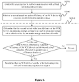
Figure 3 is a flow chart of a method for monitoring a low-temperature efficiency of a SCR device according to an embodiment of the present disclosure; -
Figure 4 is a schematic structural diagram of a vehicle post-treatment system according to an embodiment of the present disclosure; -
Figure 5 is a flow chart of a method for determining a sulfur poisoning state of a SCR device according to another embodiment of the present disclosure; and -
Figure 6 is a flow chart of a method for monitoring a low-temperature efficiency of a SCR according to another embodiment of the present disclosure. - Hereinafter, the technical solutions of the present disclosure are explained clearly and in further detail in conjunction with the drawings and specific embodiments. It is apparent that the embodiments in the following description are only some embodiments of the technical solution of the present disclosure, rather than all of the embodiments. Based on the embodiment of the present disclosure, other embodiments obtained by those skilled in the art without any creative work all fall within the scope of protection of the present disclosure.
- Referring to
Figure 1 , a method for determining a sulfur poisoning state of a SCR device is provided according to an embodiment of the present disclosure. The method is used for determining whether an SCR device of a vehicle post-treatment system is in a sulfur poisoning state. The post-treatment system includes the SCR device and a urea injector. The method for determining a sulfur poisoning state of a SCR device includes the following steps S101 and S102. - In step S101, it is determined whether the SCR device and the urea injector meet a predetermined triggering condition. If it is determined that the SCR device and the urea injector meet the predetermined triggering condition, the urea injector is controlled to stop urea injection, A first actual reduction efficiency of the SCR device is detected after the urea injection is stopped, and accumulated consumption amount of stored ammonia for a first predetermined time period after the urea injection is stopped is calculated.
- In step S102, it is determined whether the first actual reduction efficiency of the SCR device is less than a first predetermined efficiency value, and whether the accumulated consumption amount of stored ammonia is less than or equal to a consumption limit value. If it is determined that the first actual reduction efficiency of the SCR device is less than the first predetermined efficiency value, and the accumulated consumption amount of stored ammonia is less than or equal to the consumption limit value, a low-temperature efficiency of the SCR is monitored, else the process returns to step of determining whether the SCR and urea injector meet the predetermined triggering condition.
- Referring to
Figure 2 , the process of determining whether the SCR device and the urea injector meet the predetermined triggering condition includes steps S1011 and S1012. - In step S1011, a reduction efficiency of the SCR device in a first predetermined temperature range and a concentration of urea in the urea injector are monitored.
- In step S1012, when the reduction efficiency of the SCR device in the first predetermined temperature range is less than a second predetermined efficiency, and the concentration of urea is in a predetermined concentration range, it is determined that the SCR device and the urea injector meet the predetermined triggering condition.
- Referring to
Figure 3 , the process of monitoring the low-temperature efficiency of the SCR device includes steps S1021 to S1023. - In step S1021, the urea injector is controlled to perform urea injection with a fixed ammonia-nitrogen mole ratio.
- In step S1022, the second actual reduction efficiency of the SCR device for a second predetermined temperature range is monitored.
- In step S1023, in a state that the second actual reduction efficiency of the SCR device, an ammonia storage setting value and an ammonia storage value calculated by an ammonia storage model are all stable, it is determined whether a difference value between a theoretical reduction efficiency of the SCR device and the second actual reduction efficiency is greater than a difference threshold value, and if the difference value between the theoretical reduction efficiency of the SCR device and the second actual reduction efficiency is greater than the difference threshold value, it is determined that the SCR device is in the sulfur poisoning state.
- The ammonia storage setting value is determined by searching an ammonia storage mapping table according to a current space velocity and a current average temperature. The ammonia storage mapping table stores a correspondence between the space velocity, the average temperature and the ammonia storage setting value. The average temperature of the SCR device refers to an average temperature of various parts of the SCR device at a same time. Since the SCR material has a relatively large specific heat capacity, the temperature at an outlet of the SCR device may be changed later than a change in the temperature at an inlet of the SCR device. Therefore, the average temperature of various parts in the SCR device is taken as the average temperature of the SCR device.
- The ammonia storage value calculated by the ammonia storage model is calculated according to a one-dimensional physical model of the SCR device. The ammonia storage, an internal temperature, a NOx concentration in downstream gas of the SCR device and other state parameters are calculated by the model in real time according to NOx quantity in upstream gas of the SCR device, exhaust gas volume, urea injection amount, temperature and other conditions.
- The theoretical reduction efficiency of the SCR device is calculated by using the one-dimensional physical model of the SCR device, which is equal to one minus a ratio of a NOx value in downstream gas of the SCR model to a NOx value in upstream gas of the SCR model.
-
Figure 4 is a schematic structural diagram of a vehicle post-treatment system. Referring toFigure 4 , the post-treatment system includes a turbocharger (TC), a hydrocarbon (HC) injector, a urea injector, a diesel oxide catalyst (DOC) device, a diesel particulate filter (DPF), a selectively catalytic reduction (SCR) device, and multiple temperature sensors and NOx sensors. The urea injector is arranged with a high-precision urea concentration sensor to accurately detect the urea concentration. InFigure 4 ,reference sign 10 represents the turbocharger,reference sign 20 represents the diesel oxide catalyst device,reference sign 30 represents the diesel particulate filter,reference sign 40 represents the selectively catalytic reduction device,reference sign 50 represents the NOx sensors,reference sign 60 represents the urea injector andreference sign 70 represents the temperature sensor. InFigure 4 , the direction of the arrow indicates the direction of vehicle exhaust emission. The upstream gas of the SCR device refers to the vehicle exhaust inputted into the SCR device, and the downstream gas of the SCR device refers to the vehicle exhaust outputted from the SCR device (as the direction indicated by the arrow). - In the method for determining a sulfur poisoning state of a SCR device according to the embodiment of present disclosure, it is first determined whether the SCR device and the urea injector meet the predetermined triggering condition. The predetermined triggering condition involves SCR low-temperature efficiency monitoring and urea concentration monitoring. The SCR low-temperature efficiency monitoring is to monitor the reduction efficiency of the SCR device in a first predetermined temperature range, and determine whether the reduction efficiency of the SCR device in the first predetermined temperature range is less than a second predetermined efficiency. If the reduction efficiency of the SCR device in the first predetermined temperature range is less than the second predetermined efficiency, it is determined that the SCR device meets the predetermined triggering condition.
- The first predetermined temperature range may be determined according to the type of the SCR. For the copper based SCR, the first predetermined temperature range may be a range of 220 Celsius degree to 260 Celsius degree.
- The monitoring of the urea concentration range is to determine whether the concentration of urea in the urea injector is in a predetermined concentration range. If the concentration of urea is in a predetermined concentration range, it is determined that the urea injector meets the predetermined triggering condition.
- In some embodiments, the predetermined concentration range may be 32.5%±2.5%.
- If the SCR device and the urea injector meet the predetermined triggering condition, detection of ammonia storage capacity is performed. If the SCR device or the urea injector does not meet the predetermined triggering condition, the detection of ammonia storage capacity is not performed.
- In the detection of ammonia storage capacity, the urea injector is controlled to stop urea injection, the first actual reduction efficiency of the SCR device after the urea injection is stopped is detected, and the accumulated consumption amount of stored ammonia for the first predetermined time period after the urea injection is stopped is calculated.
- It is determined whether the first actual reduction efficiency of the SCR device is less than a first predetermined efficiency value, and whether the accumulated consumption amount of stored ammonia is less than or equal to a consumption limit value. In the detection of ammonia storage capacity, if the accumulated consumption amount of stored ammonia is greater than the consumption limit value, it is determined that the catalyst of SCR is not affected by sulfur, and the problem that the reduction efficiency of the SCR device in the first predetermined temperature range is less than the second predetermined efficiency is not caused by the sulfur poisoning. In this case, the process returns to the step of determining whether the SCR device and the urea injector meet the predetermined triggering condition. If the accumulated consumption amount of stored ammonia is less than or equal to the consumption limit value, since ammonia storage of the SCR is continuously consumed by NOx in upstream gas of SCR device, the first actual reduction efficiency of the SCR device will be gradually decreased. In a case that the first actual reduction efficiency of the SCR device is less than the first predetermined efficiency, and the accumulated consumption amount of stored ammonia is less than or equal to the consumption limit value, it is determined that the ammonia is not leaked and the low efficiency may be caused by sulfur poisoning or insufficient ammonia storage. In this case, the SCR low-temperature efficiency monitoring is performed.
- In some embodiments, the predetermined efficiency value may be 0.5, 0.55 and 0.45, but is not limited thereto.
- The consumption limit value is determined according to an SCR aging factor and the average temperature of the SCR device. The SCR aging factor is determined according to temperature levels experienced by the SCR device. In a case that the aging factor and the average temperature of the SCR device are determined, the consumption limit value may be determined by searching a predetermined mapping table including the correspondence between the SCR aging factor, the average temperature of the SCR device and the consumption limit value.
- The SCR low-temperature efficiency monitoring is to monitor the reduction efficiency under a condition that the average temperature of the SCR device is in a second predetermined temperature range. The second predetermined temperature range is a low operating temperature range for the SCR device. Similarly, the second predetermined temperature range is determined according to the type of SCR. For the copper based SCR, the second predetermined temperature range may be the same as the first predetermined temperature range. That is, the second predetermined temperature range may be the range of 220 Celsius degree to 260 Celsius degree. The second preset temperature range certainly may be different from the first predetermined temperature range, which is not limited in the present disclosure, and depends on the actual situation.
- In the process of monitoring the low-temperature efficiency of the SCR device, the urea injector is controlled to perform urea injection with a fixed ammonia-nitrogen mole ratio. For example, the fixed ammonia-nitrogen mole ratio may be equal to 1:1. The second actual reduction efficiency of the SCR device is monitored in the process of urea injection. In a state that the second actual reduction efficiency of the SCR device, an ammonia storage setting value and an ammonia storage value calculated by an ammonia storage model are all stable, it is determined whether a difference value between a theoretical reduction efficiency of the SCR device and the second actual reduction efficiency is greater than a difference threshold value. If the difference value between the theoretical reduction efficiency of the SCR device and the second actual reduction efficiency is greater than the difference threshold value, it is determined that the ammonia storage is not low and the SCR is in a sulfur poisoning state. If the difference value between the theoretical reduction efficiency of the SCR device and the second actual reduction efficiency is less than or equal to the difference threshold value, it is determined that the actual ammonia storage is low, and the process returns to the step of determining whether the SCR device and the urea injector meet the predetermined triggering condition.
- It can be seen from the above process, with the method for determining a sulfur poisoning state of a SCR device, it can be accurately determined whether the SCR device is in the sulfur poisoning state without being effected by other facts such as ammonia leakage, aging and ammonia storage control accuracy.
- Based on the above embodiment, referring to
Figure 5 , a method for determining a sulfur poisoning state of a SCR device according to another embodiment of the present disclosure includes steps S201 to S204. - In step S201, it is determined whether the SCR device and the urea injector meet a predetermined triggering condition. If the SCR device and the urea injector meet the predetermined triggering condition, the urea injector is controlled to stop urea injection. A first actual reduction efficiency of the SCR device is detected after the urea injection is stopped and a NOx mass flow in upstream gas of the SCR is integrated for a first predetermined time period to determine a first integral value.
- In step S202, the NOx mass flow in downstream gas of the SCR is integrated for a first predetermined time period to determine a second integral value.
- In step S203, a value of the first integral value minus the second integral value is multiplied by a molar mass ratio of ammonia to nitrogen oxide in reaction to determine accumulated consumption amount of stored ammonia for the first predetermined time period after the urea injection is stopped.
- In step S204, it is determined whether the first actual reduction efficiency of the SCR device is less than a first predetermined efficiency value and whether the accumulated consumption amount of stored ammonia is less than or equal to a consumption limit value. If the first actual reduction efficiency of the SCR device is less than the first predetermined efficiency value and the accumulated consumption amount of stored ammonia is less than or equal to the consumption limit value, a low-temperature efficiency of the SCR is monitored. If the first actual reduction efficiency of the SCR device is not less than the first predetermined efficiency value or the accumulated consumption amount of stored ammonia is greater than the consumption limit value, the process returns to the step of determining whether the SCR device and the urea injector meet the predetermined triggering condition.
- The process of determining whether the SCR device and the urea injector meet the predetermined triggering condition includes: monitoring the reduction efficiency of the SCR device in a first predetermined temperature range and a concentration of urea in the urea injector, and determining that the SCR device and the urea injector meet the predetermined triggering condition when the reduction efficiency of the SCR device in the first predetermined temperature range is less than a second predetermined efficiency and the concentration of urea is in a predetermined concentration range.
- Referring to
Figure 6 , the process of monitoring the low-temperature efficiency of the SCR device includes step S2041 to S2043. - In step S2041, the urea injector is controlled to perform urea injection with a fixed ammonia-nitrogen mole ratio.
- In step S2042, a second actual reduction efficiency of the SCR device in a second predetermined temperature range is monitored.
- In step S2043, in a state that the second actual reduction efficiency of the SCR device, an ammonia storage setting value and an ammonia storage value calculated by an ammonia storage model are all stable, it is determined whether a difference value between a theoretical reduction efficiency of the SCR device and the second actual reduction efficiency is greater than a difference threshold value. If the difference value between the theoretical reduction efficiency of the SCR device and the second actual reduction efficiency is greater than the difference threshold value, it is determined that the SCR device is in the sulfur poisoning state, and a stationary regeneration request is sent.
- A method for calculating accumulated consumption amount of stored ammonia for the first predetermined time period after the urea injection is stopped is provided according to the embodiment of the present disclosure. Furthermore, when it is determined that the SCR device is in the sulfur poisoning state, the stationary regeneration request is sent for regeneration and desulphurization to restore the performance of SCR catalyst.
- Hereinafter, a system for determining a sulfur poisoning state of a SCR device according to an embodiment of the present disclosure is described. The above method for determining a sulfur poisoning state of a SCR device may be referred to for details of the system for determining a sulfur poisoning state of a SCR device.
- The system is used for determining whether the SCR of a vehicle post-treatment system is in a sulfur poisoning state. The post-treatment system includes the SCR device and the urea injector. The system for determining a sulfur poisoning state of a SCR device includes a trigger determining module, an ammonia storage determination module and a low-temperature efficiency monitoring module.
- The trigger determining module is configured to determine whether the SCR device and the urea injector meet a predetermined triggering condition, and trigger the ammonia storage determination module if it is determined that the SCR device and the urea injector meet the predetermined triggering condition.
- The ammonia storage determination module is configured to control the urea injector to stop urea injection, detect a first actual reduction efficiency of the SCR device after the urea injection is stopped and calculate accumulated consumption amount of stored ammonia for a first predetermined time period after the urea injection is stopped.
- The ammonia storage determination module is configured to determine whether the first actual reduction efficiency of the SCR device is less than a first predetermined efficiency value and whether the accumulated consumption amount of stored ammonia is less than or equal to a consumption limit value, trigger the low-temperature efficiency monitoring module if determining that the first actual reduction efficiency of the SCR device is less than the first predetermined efficiency value, and the accumulated consumption amount of stored ammonia is less than or equal to the consumption limit value, and trigger the trigger determining module if determining that the first actual reduction efficiency of the SCR device is not less than the first predetermined efficiency value, or the accumulated consumption amount of stored ammonia is greater than the consumption limit value.
- The low-temperature efficiency monitoring module is configured to monitor the low-temperature efficiency of the SCR device by controlling the urea injector to perform urea injection with a fixed ammonia-nitrogen mole ratio, and monitoring a second actual reduction efficiency of the SCR device in a second predetermined temperature range, and determining, in a state that the second actual reduction efficiency of the SCR device, an ammonia storage setting value and an ammonia storage value calculated by an ammonia storage model are all stable, whether a difference value between a theoretical reduction efficiency of the SCR device and the second actual reduction efficiency is greater than a difference threshold value, and determining that the SCR is in a sulfur poisoning state if the difference value between the theoretical reduction efficiency of the SCR device and the second actual reduction efficiency is greater than the difference threshold value.
- The trigger determining module is configured to determine whether the SCR device and the urea injector meet the predetermined triggering condition by monitoring a reduction efficiency of the SCR device in the first predetermined temperature range and a concentration of urea in the urea injector, and determining that the SCR device and the urea injector meet the predetermined triggering condition when the reduction efficiency of the SCR device for the first predetermined temperature range is less than the second predetermined efficiency, and the concentration of urea is in a predetermined concentration range.
- In some embodiments, the ammonia storage determination module is configured to calculate the accumulated consumption amount of stored ammonia for the first predetermined time period after the urea injection is stopped, by integrating a NOx mass flow in upstream gas of the SCR device for the first predetermined time period to determine a first integral value; integrating a NOx mass flow in downstream gas of the SCR device for the first predetermined time period to determine a second integral value; and multiplying a value of the first integral value minus the second integral value by a molar mass ratio of ammonia to nitrogen oxide in reaction to determine the accumulated consumption amount of stored ammonia for the first predetermined time period after the urea injection is stopped.
- In some embodiments, the predetermined concentration range may be 32.5%±2.5%.
- In some embodiments, the low-temperature efficiency monitoring module may be further configured to send a stationary regeneration request when determining that the SCR device is in the sulfur poisoning state.
- In some embodiments, the consumption limit value may be determined according to an aging factor and an average temperature of the SCR device.
- In summary, the method and the system for determining a sulfur poisoning state of a SCR device are provided according to the embodiments of the present disclosure. In the method for determining a sulfur poisoning state of a SCR device, if the reduction efficiency of the SCR device and the concentration of urea meet the predetermined triggering condition, the ammonia storage capacity is detected. In the process of detecting ammonia storage capacity, the urea injection is stopped and the accumulated consumption amount of stored ammonia is calculated. If the accumulated consumption amount of stored ammonia is greater than the consumption limit value, it is determined that there is large ammonia storage. Therefore the subsequent detection is not performed, and the process of sulfur poisoning determination ends. If the accumulated consumption amount of stored ammonia is less than or equal to the consumption limit value, since the ammonia storage of the SCR is continuously consumed by NOx in upstream gas of SCR, and the first actual reduction efficiency of the SCR device will be gradually decreased. In a case that the accumulated consumption amount of stored ammonia is less than or equal to the consumption limit value and the first actual reduction efficiency of the SCR device is less than the first predetermined efficiency value, it is determined that ammonia is not leaked, and the problem of low reduction efficiency of the SCR device may be caused by sulfur poisoning or insufficient ammonia storage. In this case, the low-temperature efficiency of the SCR is required to be monitored. In the process of monitoring low-temperature efficiency of the SCR device, if the difference value between the theoretical reduction efficiency of the SCR device and the second actual reduction efficiency is greater than the difference threshold value, it is determined that the SCR device is in the sulfur poisoning state. It can be seen from the above process, whether the SCR device is in the sulfur poisoning state can be accurately determined by the method without being effected by other facts such as ammonia leakage, aging, ammonia storage control accuracy.
- The embodiments in the present disclosure are described in a progressive manner, each of which emphasizes differences from others. The same or similar parts among the embodiments can be referred to each other.
- Based on the above description of the disclosed embodiments, those skilled in the art can implement or use the present disclosure.
Claims (10)
- A method for determining a sulfur poisoning state of a selective catalytic reduction (SCR) device of a vehicle post-treatment system, wherein the vehicle post-treatment system comprises the SCR device (40) and a urea injector (60), and the method comprises:determining whether the SCR device and the urea injector meet a predetermined triggering condition; if it is determined that the SCR device and the urea injector meet the predetermined triggering condition, controlling the urea injector to stop urea injection; and detecting a first actual reduction efficiency of the SCR device after the urea injection is stopped and calculating accumulated consumption amount of stored ammonia for a first predetermined time period after the urea injection is stopped; anddetermining whether the first actual reduction efficiency of the SCR device is less than a first predetermined efficiency value, and whether the accumulated consumption amount of stored ammonia is less than or equal to a consumption limit value; if it is determined that the first actual reduction efficiency of the SCR device is less than the first predetermined efficiency value and the accumulated consumption amount of stored ammonia is less than or equal to the consumption limit value, monitoring a low-temperature efficiency of the SCR device; if it is determined that the first actual reduction efficiency of the SCR device is not less than the first predetermined efficiency value, or the accumulated consumption amount of stored ammonia is greater than the consumption limit value, returning to the step of determining whether the SCR device and the urea injector meet the predetermined triggering condition;wherein the determining whether the SCR device and the urea injector meet a predetermined triggering condition comprises:monitoring a reduction efficiency of the SCR device in a first predetermined temperature range and a concentration of urea in the urea injector; and determining that the SCR device and the urea injector meet the predetermined triggering condition when the reduction efficiency of the SCR device in the first predetermined temperature range is less than a second predetermined efficiency and the concentration of urea is in a predetermined concentration range; andwherein the monitoring a low-temperature efficiency of the SCR device comprises:controlling the urea injector to perform urea injection with a fixed ammonia-nitrogen mole ratio, and monitoring a second actual reduction efficiency of the SCR device in a second predetermined temperature range;determining, in a state that the second actual reduction efficiency of the SCR device, an ammonia storage setting value and an ammonia storage value calculated by an ammonia storage model are all stable, whether a difference value between a theoretical reduction efficiency of the SCR device and the second actual reduction efficiency is greater than a difference threshold value; anddetermining that the SCR device is in the sulfur poisoning state if the difference value between the theoretical reduction efficiency of the SCR device and the second actual reduction efficiency is greater than the difference threshold value.
- The method for determining a sulfur poisoning state of a SCR device according to claim 1, wherein the calculating accumulated consumption amount of stored ammonia for a first predetermined time period after the urea injection is stopped comprises:integrating a nitrogen oxides (NOx) mass flow in upstream gas of the SCR device for the first predetermined time period to determine a first integral value;integrating a NOx mass flow in downstream gas of the SCR device for the first predetermined time period to determine a second integral value; andmultiplying a value of the first integral value minus the second integral value by a molar mass ratio of ammonia to nitrogen oxide in reaction, to determine the accumulated consumption amount of stored ammonia for the first predetermined time period after the urea injection is stopped.
- The method for determining a sulfur poisoning state of a SCR device according to claim 1, wherein the predetermined concentration range is 32.5%±2.5%.
- The method for determining a sulfur poisoning state of a SCR device according to claim 1, wherein after determining that the SCR device is in the sulfur poisoning state, the method further comprises:
sending a stationary regeneration request. - The method for determining a sulfur poisoning state of a SCR device according to claim 1, wherein the consumption limit value is determined according to an aging factor and an average temperature of the SCR device.
- A system for determining a sulfur poisoning state of a selective catalytic reduction (SCR) device of a vehicle post-treatment system, wherein the vehicle post-treatment system comprises the SCR device (40) and a urea injector (60), and the system for determining the sulfur poisoning state comprises:an trigger determining module, configured to determine whether the SCR device and the urea injector meet a predetermined triggering condition, and trigger an ammonia storage determination module if it is determined that the SCR device and the urea injector meet the predetermined triggering condition;the ammonia storage determination module, configured tocontrol the urea injector to stop urea injection;detect a first actual reduction efficiency of the SCR device after the urea injection is stopped and calculate accumulated consumption amount of stored ammonia for a first predetermined time period after the urea injection is stopped;determine whether the first actual reduction efficiency of the SCR device is less than a first predetermined efficiency value, and whether the accumulated consumption amount of stored ammonia is less than or equal to a consumption limit value;trigger a low-temperature efficiency monitoring module if it is determined that the first actual reduction efficiency of the SCR device is less than the first predetermined efficiency value and the accumulated consumption amount of stored ammonia is less than or equal to the consumption limit value; andtrigger the trigger determining module, if it is determined that the first actual reduction efficiency of the SCR device is not less than the first predetermined efficiency value, or the accumulated consumption amount of stored ammonia is greater than the consumption limit value; andthe low-temperature efficiency monitoring module, configured to monitor a low-temperature efficiency of the SCR device by controlling the urea injector to perform urea injection with a fixed ammonia-nitrogen mole ratio, and monitoring a second actual reduction efficiency of the SCR device in a second predetermined temperature range; determining, in a state that the second actual reduction efficiency of the SCR device, an ammonia storage setting value and an ammonia storage value calculated by an ammonia storage model are all stable, whether a difference value between a theoretical reduction efficiency of the SCR device and the second actual reduction efficiency is greater than a difference threshold value; and determining that the SCR device is in the sulfur poisoning state if the difference value between the theoretical reduction efficiency of the SCR device and the second actual reduction efficiency is greater than the difference threshold value;wherein the trigger determining module is configured to determine whether the SCR device and the urea injector meet the predetermined triggering condition by: monitoring a reduction efficiency of the SCR device in a first predetermined temperature range and a concentration of urea in the urea injector; and determining that the SCR device and the urea injector meet the predetermined triggering condition, when the reduction efficiency of the SCR device in the first predetermined temperature range is less than a second predetermined efficiency and the concentration of urea is in a predetermined concentration range.
- The system for determining a sulfur poisoning state of a SCR device according to claim 6, wherein the ammonia storage determination module is configured to:integrate a nitrogen oxides (NOx) mass flow in upstream gas of the SCR device for the first predetermined time period to determine a first integral value;integrate a NOx mass flow in downstream gas of the SCR device for the first predetermined time period to determine a second integral value; andmultiply a value of the first integral value minus the second integral value by a molar mass ratio of ammonia to nitrogen oxide in reaction, to determine the accumulated consumption amount of stored ammonia for the first predetermined time period after the urea injection is stopped.
- The system for determining a sulfur poisoning state of a SCR device according to claim 6, wherein the predetermined concentration range is 32.5%±2.5%.
- The system for determining a sulfur poisoning state of a SCR device according to claim 6, wherein the low-temperature efficiency monitoring module is further configured to send a stationary regeneration request after determining that the SCR device is in the sulfur poisoning state.
- The system for determining a sulfur poisoning state of a SCR device according to claim 6, wherein the consumption limit value is determined according to an aging factor and an average temperature of the SCR device.
Applications Claiming Priority (1)
| Application Number | Priority Date | Filing Date | Title |
|---|---|---|---|
| CN201911361702.1A CN110761882B (en) | 2019-12-26 | 2019-12-26 | Method and system for judging SCR sulfur poisoning |
Publications (2)
| Publication Number | Publication Date |
|---|---|
| EP3842624A1 EP3842624A1 (en) | 2021-06-30 |
| EP3842624B1 true EP3842624B1 (en) | 2022-07-13 |
Family
ID=69341654
Family Applications (1)
| Application Number | Title | Priority Date | Filing Date |
|---|---|---|---|
| EP20196612.4A Active EP3842624B1 (en) | 2019-12-26 | 2020-09-17 | Method and system for determining sulfur poisoning state of selectively catalytic reduction device |
Country Status (2)
| Country | Link |
|---|---|
| EP (1) | EP3842624B1 (en) |
| CN (1) | CN110761882B (en) |
Families Citing this family (23)
| Publication number | Priority date | Publication date | Assignee | Title |
|---|---|---|---|---|
| CN113946173B (en) * | 2020-07-15 | 2022-12-06 | 中冶长天国际工程有限责任公司 | Temperature control system, method and device for analytical tower |
| CN112594044B (en) * | 2020-12-14 | 2022-04-26 | 潍柴动力股份有限公司 | Aging prediction method and device for post-processing system |
| CN112682134B (en) * | 2020-12-25 | 2022-04-26 | 潍柴动力股份有限公司 | Parking regeneration system and parking regeneration method of aftertreatment system |
| CN112696251A (en) * | 2020-12-29 | 2021-04-23 | 潍柴动力股份有限公司 | SCR conversion efficiency recovery method and device and vehicle |
| CN112814770B (en) * | 2020-12-31 | 2022-04-05 | 潍柴动力股份有限公司 | Uniformity evaluation method and device of parallel SCR system |
| CN113417726B (en) * | 2021-06-25 | 2022-07-15 | 潍柴动力股份有限公司 | Detecting method for ammonia leakage in post-processing system and controller of post-processing system |
| CN113488115B (en) * | 2021-07-28 | 2024-10-22 | 潍柴动力股份有限公司 | A method and device for detecting sulfur poisoning |
| CN113803143B (en) * | 2021-09-02 | 2022-09-23 | 潍柴动力股份有限公司 | DOC sulfur poisoning judgment method and control device with same |
| CN113864048B (en) * | 2021-09-28 | 2024-04-02 | 昆山三一动力有限公司 | High sulfur oil identification processing method, device, vehicle and computer readable storage medium |
| CN113756921B (en) * | 2021-09-29 | 2023-01-06 | 潍柴动力股份有限公司 | Method, device, vehicle and medium for determining sulfur poisoning in SCR system |
| CN113790094B (en) * | 2021-09-29 | 2022-10-25 | 潍柴动力股份有限公司 | Method, device, vehicle and medium for determining sulfur poisoning of aftertreatment system |
| CN114964793B (en) * | 2022-04-24 | 2024-07-19 | 潍柴动力股份有限公司 | SDPF ash load detection method and equipment, monitoring method and device, vehicle |
| CN114961956B (en) * | 2022-07-06 | 2023-12-15 | 潍柴动力股份有限公司 | Selective catalytic reduction conversion efficiency diagnosis method and device |
| CN115419841B (en) * | 2022-10-13 | 2025-07-18 | 潍柴动力股份有限公司 | Ammonia leak detection method, ammonia leak detection device, readable storage medium, and ammonia leak detection system |
| CN115628128B (en) * | 2022-11-02 | 2024-05-14 | 一汽解放汽车有限公司 | Gas-driven urea system fault automatic detection method, device, system and storage medium |
| CN115653735B (en) * | 2022-12-27 | 2023-04-07 | 卓品智能科技无锡股份有限公司 | Method and system for recovering diesel engine SCR sulfur poisoning |
| CN115977769B (en) * | 2023-02-01 | 2026-02-17 | 常州易控汽车电子股份有限公司 | Method and device for judging maximum performance of SCR |
| CN116066223B (en) * | 2023-02-22 | 2025-07-18 | 潍柴动力股份有限公司 | Method and device for detecting urea consumption deviation fault, processor and vehicle |
| CN116950745B (en) * | 2023-07-27 | 2026-02-24 | 三一重型装备有限公司 | Engine thermal management method, system, electronic equipment, engine and vehicle |
| CN117869043B (en) * | 2024-01-09 | 2025-12-26 | 潍柴动力股份有限公司 | Methods, apparatus, storage media and electronic devices for preventing N2O generation |
| CN118110589B (en) * | 2024-03-13 | 2026-01-23 | 潍柴动力股份有限公司 | Desulfurization method, equipment, vehicle and medium of SCR system |
| CN118622445B (en) * | 2024-06-24 | 2025-11-18 | 潍柴动力股份有限公司 | Monitoring methods, devices, and electronic equipment for DOC sulfur poisoning |
| CN118934174B (en) * | 2024-07-31 | 2025-09-23 | 广西玉柴机器股份有限公司 | A NOx and N2O emission suppression control method based on ammonia storage synergy |
Family Cites Families (13)
| Publication number | Priority date | Publication date | Assignee | Title |
|---|---|---|---|---|
| KR100821793B1 (en) * | 2005-12-12 | 2008-04-11 | 현대자동차주식회사 | NOx storage catalyst regeneration method |
| DE602006015210D1 (en) * | 2006-12-22 | 2010-08-12 | Ford Global Tech Llc | An internal combustion engine system and method for determining the condition of an exhaust treatment device in such a system |
| US8091416B2 (en) * | 2009-01-16 | 2012-01-10 | GM Global Technology Operations LLC | Robust design of diagnostic enabling conditions for SCR NOx conversion efficiency monitor |
| SE538378C2 (en) * | 2012-05-03 | 2016-06-07 | Scania Cv Ab | Method for detecting sulfur poisoning in an exhaust after-treatment system |
| US9657665B2 (en) * | 2013-02-25 | 2017-05-23 | Cummins Inc. | System, method, and apparatus for sulfur recovery on an SCR catalyst |
| US20140331644A1 (en) * | 2013-05-08 | 2014-11-13 | Cummins Ip, Inc. | Exhaust aftertreatment component condition estimation and regeneration |
| JP6252518B2 (en) * | 2015-03-04 | 2017-12-27 | トヨタ自動車株式会社 | Exhaust gas purification device for internal combustion engine |
| JP6278039B2 (en) * | 2015-12-14 | 2018-02-14 | トヨタ自動車株式会社 | Degradation diagnosis device for selective catalytic reduction catalyst |
| KR101816430B1 (en) * | 2016-08-17 | 2018-02-21 | 현대자동차주식회사 | Control method of exhaust gas purification system |
| US11549423B2 (en) * | 2017-01-16 | 2023-01-10 | Scania Cv Ab | System and a method for determining a cause for impaired performance of a catalytic configuration |
| US10215072B2 (en) * | 2017-03-23 | 2019-02-26 | GM Global Technology Operations LLC | Methods for controlling and detecting catalyst poisoning of selective catalytic reduction devices |
| CN108295891B (en) * | 2018-01-10 | 2021-04-06 | 绍兴文理学院 | In-situ regeneration system and method of Cu-based molecular sieve denitration catalyst for diesel vehicle tail gas purification |
| CN109707494B (en) * | 2018-12-28 | 2020-04-24 | 潍柴动力股份有限公司 | Treatment method and device for post-treatment of sulfur poisoning |
-
2019
- 2019-12-26 CN CN201911361702.1A patent/CN110761882B/en active Active
-
2020
- 2020-09-17 EP EP20196612.4A patent/EP3842624B1/en active Active
Also Published As
| Publication number | Publication date |
|---|---|
| EP3842624A1 (en) | 2021-06-30 |
| CN110761882B (en) | 2020-04-07 |
| CN110761882A (en) | 2020-02-07 |
Similar Documents
| Publication | Publication Date | Title |
|---|---|---|
| EP3842624A1 (en) | Method and system for determining sulfur poisoning state of selectively catalytic reduction device | |
| EP2551480B1 (en) | Engine exhaust purification device | |
| CN113669143B (en) | Performance detection method, detection device and medium for tail gas aftertreatment system | |
| EP2126306B1 (en) | On-board-diagnosis method for an exhaust aftertreatment system and on-board-diagnosis system for an exhaust aftertreatment system | |
| US9957872B2 (en) | Abnormality diagnosing apparatus | |
| US20110296905A1 (en) | Method for monitoring an scr catalytic converter | |
| US20130227935A1 (en) | Diagnostics for hydrocarbon injection for filter regeneration | |
| CN101278110A (en) | Diagnostic method for an exhaust gas aftertreatment system | |
| CN110645076A (en) | NH based on model3Leak diagnosis method | |
| US10662847B2 (en) | Integrated start/stop and after-treatment controls | |
| CN113756921B (en) | Method, device, vehicle and medium for determining sulfur poisoning in SCR system | |
| CN116066223B (en) | Method and device for detecting urea consumption deviation fault, processor and vehicle | |
| CN110131024B (en) | A kind of leakage detection method and device of urea | |
| CN116085097A (en) | Vehicle aftertreatment system control method and device, storage medium and vehicle | |
| US10100701B2 (en) | Method for the diagnosis of an exhaust gas aftertreatment system for an internal combustion engine | |
| CN112177714A (en) | SCR system conversion rate monitoring method, device, equipment and storage medium | |
| CN115095416A (en) | Method, device and system for detecting vehicle tail gas signal | |
| EP3401522B1 (en) | Exhaust gas control system for internal combustion engine and method of controlling exhaust gas control system for internal combustion engine | |
| US8434298B2 (en) | Method for injecting ammonia into an exhaust gas stream | |
| CN110872975B (en) | Method for controlling and/or regulating an SCR catalytic converter of an internal combustion engine arranged in a motor vehicle | |
| CN114033538A (en) | Double DPF regeneration control method and device and engine | |
| CN116291818B (en) | Determination method, control method, controller and SCR (selective catalytic reduction) system for ammonia demand | |
| JP6149686B2 (en) | HC catalyst poisoning detection system for SCR catalyst and HC catalyst poisoning detection method for SCR catalyst | |
| KR102571849B1 (en) | Method for predicting and controlling reducing agent occlusion amount of simultaneous removal device having heat source | |
| CN104040153A (en) | Optimized management of an scr catalyst by means of the periodic regeneration of a particle filter |
Legal Events
| Date | Code | Title | Description |
|---|---|---|---|
| PUAI | Public reference made under article 153(3) epc to a published international application that has entered the european phase |
Free format text: ORIGINAL CODE: 0009012 |
|
| STAA | Information on the status of an ep patent application or granted ep patent |
Free format text: STATUS: REQUEST FOR EXAMINATION WAS MADE |
|
| 17P | Request for examination filed |
Effective date: 20200917 |
|
| AK | Designated contracting states |
Kind code of ref document: A1 Designated state(s): AL AT BE BG CH CY CZ DE DK EE ES FI FR GB GR HR HU IE IS IT LI LT LU LV MC MK MT NL NO PL PT RO RS SE SI SK SM TR |
|
| GRAP | Despatch of communication of intention to grant a patent |
Free format text: ORIGINAL CODE: EPIDOSNIGR1 |
|
| STAA | Information on the status of an ep patent application or granted ep patent |
Free format text: STATUS: GRANT OF PATENT IS INTENDED |
|
| INTG | Intention to grant announced |
Effective date: 20220127 |
|
| GRAS | Grant fee paid |
Free format text: ORIGINAL CODE: EPIDOSNIGR3 |
|
| GRAA | (expected) grant |
Free format text: ORIGINAL CODE: 0009210 |
|
| STAA | Information on the status of an ep patent application or granted ep patent |
Free format text: STATUS: THE PATENT HAS BEEN GRANTED |
|
| AK | Designated contracting states |
Kind code of ref document: B1 Designated state(s): AL AT BE BG CH CY CZ DE DK EE ES FI FR GB GR HR HU IE IS IT LI LT LU LV MC MK MT NL NO PL PT RO RS SE SI SK SM TR |
|
| REG | Reference to a national code |
Ref country code: CH Ref legal event code: EP |
|
| REG | Reference to a national code |
Ref country code: DE Ref legal event code: R096 Ref document number: 602020003975 Country of ref document: DE |
|
| REG | Reference to a national code |
Ref country code: AT Ref legal event code: REF Ref document number: 1504404 Country of ref document: AT Kind code of ref document: T Effective date: 20220815 |
|
| REG | Reference to a national code |
Ref country code: IE Ref legal event code: FG4D |
|
| REG | Reference to a national code |
Ref country code: SE Ref legal event code: TRGR |
|
| REG | Reference to a national code |
Ref country code: LT Ref legal event code: MG9D |
|
| REG | Reference to a national code |
Ref country code: NL Ref legal event code: MP Effective date: 20220713 |
|
| PG25 | Lapsed in a contracting state [announced via postgrant information from national office to epo] |
Ref country code: RS Free format text: LAPSE BECAUSE OF FAILURE TO SUBMIT A TRANSLATION OF THE DESCRIPTION OR TO PAY THE FEE WITHIN THE PRESCRIBED TIME-LIMIT Effective date: 20220713 Ref country code: PT Free format text: LAPSE BECAUSE OF FAILURE TO SUBMIT A TRANSLATION OF THE DESCRIPTION OR TO PAY THE FEE WITHIN THE PRESCRIBED TIME-LIMIT Effective date: 20221114 Ref country code: NO Free format text: LAPSE BECAUSE OF FAILURE TO SUBMIT A TRANSLATION OF THE DESCRIPTION OR TO PAY THE FEE WITHIN THE PRESCRIBED TIME-LIMIT Effective date: 20221013 Ref country code: NL Free format text: LAPSE BECAUSE OF FAILURE TO SUBMIT A TRANSLATION OF THE DESCRIPTION OR TO PAY THE FEE WITHIN THE PRESCRIBED TIME-LIMIT Effective date: 20220713 Ref country code: LV Free format text: LAPSE BECAUSE OF FAILURE TO SUBMIT A TRANSLATION OF THE DESCRIPTION OR TO PAY THE FEE WITHIN THE PRESCRIBED TIME-LIMIT Effective date: 20220713 Ref country code: LT Free format text: LAPSE BECAUSE OF FAILURE TO SUBMIT A TRANSLATION OF THE DESCRIPTION OR TO PAY THE FEE WITHIN THE PRESCRIBED TIME-LIMIT Effective date: 20220713 Ref country code: FI Free format text: LAPSE BECAUSE OF FAILURE TO SUBMIT A TRANSLATION OF THE DESCRIPTION OR TO PAY THE FEE WITHIN THE PRESCRIBED TIME-LIMIT Effective date: 20220713 Ref country code: ES Free format text: LAPSE BECAUSE OF FAILURE TO SUBMIT A TRANSLATION OF THE DESCRIPTION OR TO PAY THE FEE WITHIN THE PRESCRIBED TIME-LIMIT Effective date: 20220713 |
|
| PG25 | Lapsed in a contracting state [announced via postgrant information from national office to epo] |
Ref country code: PL Free format text: LAPSE BECAUSE OF FAILURE TO SUBMIT A TRANSLATION OF THE DESCRIPTION OR TO PAY THE FEE WITHIN THE PRESCRIBED TIME-LIMIT Effective date: 20220713 Ref country code: IS Free format text: LAPSE BECAUSE OF FAILURE TO SUBMIT A TRANSLATION OF THE DESCRIPTION OR TO PAY THE FEE WITHIN THE PRESCRIBED TIME-LIMIT Effective date: 20221113 Ref country code: HR Free format text: LAPSE BECAUSE OF FAILURE TO SUBMIT A TRANSLATION OF THE DESCRIPTION OR TO PAY THE FEE WITHIN THE PRESCRIBED TIME-LIMIT Effective date: 20220713 Ref country code: GR Free format text: LAPSE BECAUSE OF FAILURE TO SUBMIT A TRANSLATION OF THE DESCRIPTION OR TO PAY THE FEE WITHIN THE PRESCRIBED TIME-LIMIT Effective date: 20221014 |
|
| REG | Reference to a national code |
Ref country code: DE Ref legal event code: R097 Ref document number: 602020003975 Country of ref document: DE |
|
| PG25 | Lapsed in a contracting state [announced via postgrant information from national office to epo] |
Ref country code: SM Free format text: LAPSE BECAUSE OF FAILURE TO SUBMIT A TRANSLATION OF THE DESCRIPTION OR TO PAY THE FEE WITHIN THE PRESCRIBED TIME-LIMIT Effective date: 20220713 Ref country code: RO Free format text: LAPSE BECAUSE OF FAILURE TO SUBMIT A TRANSLATION OF THE DESCRIPTION OR TO PAY THE FEE WITHIN THE PRESCRIBED TIME-LIMIT Effective date: 20220713 Ref country code: MC Free format text: LAPSE BECAUSE OF FAILURE TO SUBMIT A TRANSLATION OF THE DESCRIPTION OR TO PAY THE FEE WITHIN THE PRESCRIBED TIME-LIMIT Effective date: 20220713 Ref country code: DK Free format text: LAPSE BECAUSE OF FAILURE TO SUBMIT A TRANSLATION OF THE DESCRIPTION OR TO PAY THE FEE WITHIN THE PRESCRIBED TIME-LIMIT Effective date: 20220713 Ref country code: CZ Free format text: LAPSE BECAUSE OF FAILURE TO SUBMIT A TRANSLATION OF THE DESCRIPTION OR TO PAY THE FEE WITHIN THE PRESCRIBED TIME-LIMIT Effective date: 20220713 |
|
| PLBE | No opposition filed within time limit |
Free format text: ORIGINAL CODE: 0009261 |
|
| STAA | Information on the status of an ep patent application or granted ep patent |
Free format text: STATUS: NO OPPOSITION FILED WITHIN TIME LIMIT |
|
| REG | Reference to a national code |
Ref country code: BE Ref legal event code: MM Effective date: 20220930 |
|
| PG25 | Lapsed in a contracting state [announced via postgrant information from national office to epo] |
Ref country code: SK Free format text: LAPSE BECAUSE OF FAILURE TO SUBMIT A TRANSLATION OF THE DESCRIPTION OR TO PAY THE FEE WITHIN THE PRESCRIBED TIME-LIMIT Effective date: 20220713 Ref country code: EE Free format text: LAPSE BECAUSE OF FAILURE TO SUBMIT A TRANSLATION OF THE DESCRIPTION OR TO PAY THE FEE WITHIN THE PRESCRIBED TIME-LIMIT Effective date: 20220713 |
|
| 26N | No opposition filed |
Effective date: 20230414 |
|
| PG25 | Lapsed in a contracting state [announced via postgrant information from national office to epo] |
Ref country code: LU Free format text: LAPSE BECAUSE OF NON-PAYMENT OF DUE FEES Effective date: 20220917 Ref country code: AL Free format text: LAPSE BECAUSE OF FAILURE TO SUBMIT A TRANSLATION OF THE DESCRIPTION OR TO PAY THE FEE WITHIN THE PRESCRIBED TIME-LIMIT Effective date: 20220713 |
|
| PG25 | Lapsed in a contracting state [announced via postgrant information from national office to epo] |
Ref country code: IE Free format text: LAPSE BECAUSE OF NON-PAYMENT OF DUE FEES Effective date: 20220917 |
|
| PG25 | Lapsed in a contracting state [announced via postgrant information from national office to epo] |
Ref country code: SI Free format text: LAPSE BECAUSE OF FAILURE TO SUBMIT A TRANSLATION OF THE DESCRIPTION OR TO PAY THE FEE WITHIN THE PRESCRIBED TIME-LIMIT Effective date: 20220713 |
|
| PG25 | Lapsed in a contracting state [announced via postgrant information from national office to epo] |
Ref country code: BE Free format text: LAPSE BECAUSE OF NON-PAYMENT OF DUE FEES Effective date: 20220930 |
|
| PG25 | Lapsed in a contracting state [announced via postgrant information from national office to epo] |
Ref country code: CY Free format text: LAPSE BECAUSE OF FAILURE TO SUBMIT A TRANSLATION OF THE DESCRIPTION OR TO PAY THE FEE WITHIN THE PRESCRIBED TIME-LIMIT Effective date: 20220713 |
|
| REG | Reference to a national code |
Ref country code: CH Ref legal event code: PL |
|
| PG25 | Lapsed in a contracting state [announced via postgrant information from national office to epo] |
Ref country code: MK Free format text: LAPSE BECAUSE OF FAILURE TO SUBMIT A TRANSLATION OF THE DESCRIPTION OR TO PAY THE FEE WITHIN THE PRESCRIBED TIME-LIMIT Effective date: 20220713 Ref country code: HU Free format text: LAPSE BECAUSE OF FAILURE TO SUBMIT A TRANSLATION OF THE DESCRIPTION OR TO PAY THE FEE WITHIN THE PRESCRIBED TIME-LIMIT; INVALID AB INITIO Effective date: 20200917 |
|
| PG25 | Lapsed in a contracting state [announced via postgrant information from national office to epo] |
Ref country code: CH Free format text: LAPSE BECAUSE OF NON-PAYMENT OF DUE FEES Effective date: 20230930 |
|
| PG25 | Lapsed in a contracting state [announced via postgrant information from national office to epo] |
Ref country code: CH Free format text: LAPSE BECAUSE OF NON-PAYMENT OF DUE FEES Effective date: 20230930 Ref country code: BG Free format text: LAPSE BECAUSE OF FAILURE TO SUBMIT A TRANSLATION OF THE DESCRIPTION OR TO PAY THE FEE WITHIN THE PRESCRIBED TIME-LIMIT Effective date: 20220713 |
|
| PG25 | Lapsed in a contracting state [announced via postgrant information from national office to epo] |
Ref country code: MT Free format text: LAPSE BECAUSE OF FAILURE TO SUBMIT A TRANSLATION OF THE DESCRIPTION OR TO PAY THE FEE WITHIN THE PRESCRIBED TIME-LIMIT Effective date: 20220713 |
|
| PGFP | Annual fee paid to national office [announced via postgrant information from national office to epo] |
Ref country code: IT Payment date: 20250925 Year of fee payment: 6 |
|
| PGFP | Annual fee paid to national office [announced via postgrant information from national office to epo] |
Ref country code: FR Payment date: 20250930 Year of fee payment: 6 Ref country code: AT Payment date: 20251001 Year of fee payment: 6 |
|
| PGFP | Annual fee paid to national office [announced via postgrant information from national office to epo] |
Ref country code: SE Payment date: 20250924 Year of fee payment: 6 |
|
| PG25 | Lapsed in a contracting state [announced via postgrant information from national office to epo] |
Ref country code: TR Free format text: LAPSE BECAUSE OF FAILURE TO SUBMIT A TRANSLATION OF THE DESCRIPTION OR TO PAY THE FEE WITHIN THE PRESCRIBED TIME-LIMIT Effective date: 20220713 |
|
| PGFP | Annual fee paid to national office [announced via postgrant information from national office to epo] |
Ref country code: DE Payment date: 20251015 Year of fee payment: 6 |
|
| PGFP | Annual fee paid to national office [announced via postgrant information from national office to epo] |
Ref country code: GB Payment date: 20251023 Year of fee payment: 6 |