EP3842623A1 - Lost motion mechanism, valve gear and engine - Google Patents
Lost motion mechanism, valve gear and engine Download PDFInfo
- Publication number
- EP3842623A1 EP3842623A1 EP20216365.5A EP20216365A EP3842623A1 EP 3842623 A1 EP3842623 A1 EP 3842623A1 EP 20216365 A EP20216365 A EP 20216365A EP 3842623 A1 EP3842623 A1 EP 3842623A1
- Authority
- EP
- European Patent Office
- Prior art keywords
- lost motion
- motion mechanism
- protrusion
- engine
- support
- Prior art date
- Legal status (The legal status is an assumption and is not a legal conclusion. Google has not performed a legal analysis and makes no representation as to the accuracy of the status listed.)
- Granted
Links
Images








Classifications
-
- F—MECHANICAL ENGINEERING; LIGHTING; HEATING; WEAPONS; BLASTING
- F01—MACHINES OR ENGINES IN GENERAL; ENGINE PLANTS IN GENERAL; STEAM ENGINES
- F01L—CYCLICALLY OPERATING VALVES FOR MACHINES OR ENGINES
- F01L1/00—Valve-gear or valve arrangements, e.g. lift-valve gear
- F01L1/46—Component parts, details, or accessories, not provided for in preceding subgroups
- F01L1/462—Valve return spring arrangements
-
- F—MECHANICAL ENGINEERING; LIGHTING; HEATING; WEAPONS; BLASTING
- F01—MACHINES OR ENGINES IN GENERAL; ENGINE PLANTS IN GENERAL; STEAM ENGINES
- F01L—CYCLICALLY OPERATING VALVES FOR MACHINES OR ENGINES
- F01L1/00—Valve-gear or valve arrangements, e.g. lift-valve gear
- F01L1/12—Transmitting gear between valve drive and valve
- F01L1/18—Rocking arms or levers
- F01L1/185—Overhead end-pivot rocking arms
-
- F—MECHANICAL ENGINEERING; LIGHTING; HEATING; WEAPONS; BLASTING
- F01—MACHINES OR ENGINES IN GENERAL; ENGINE PLANTS IN GENERAL; STEAM ENGINES
- F01L—CYCLICALLY OPERATING VALVES FOR MACHINES OR ENGINES
- F01L1/00—Valve-gear or valve arrangements, e.g. lift-valve gear
- F01L1/26—Valve-gear or valve arrangements, e.g. lift-valve gear characterised by the provision of two or more valves operated simultaneously by same transmitting-gear; peculiar to machines or engines with more than two lift-valves per cylinder
- F01L1/267—Valve-gear or valve arrangements, e.g. lift-valve gear characterised by the provision of two or more valves operated simultaneously by same transmitting-gear; peculiar to machines or engines with more than two lift-valves per cylinder with means for varying the timing or the lift of the valves
-
- F—MECHANICAL ENGINEERING; LIGHTING; HEATING; WEAPONS; BLASTING
- F01—MACHINES OR ENGINES IN GENERAL; ENGINE PLANTS IN GENERAL; STEAM ENGINES
- F01L—CYCLICALLY OPERATING VALVES FOR MACHINES OR ENGINES
- F01L13/00—Modifications of valve-gear to facilitate reversing, braking, starting, changing compression ratio, or other specific operations
- F01L13/0005—Deactivating valves
-
- F—MECHANICAL ENGINEERING; LIGHTING; HEATING; WEAPONS; BLASTING
- F01—MACHINES OR ENGINES IN GENERAL; ENGINE PLANTS IN GENERAL; STEAM ENGINES
- F01L—CYCLICALLY OPERATING VALVES FOR MACHINES OR ENGINES
- F01L13/00—Modifications of valve-gear to facilitate reversing, braking, starting, changing compression ratio, or other specific operations
- F01L13/0015—Modifications of valve-gear to facilitate reversing, braking, starting, changing compression ratio, or other specific operations for optimising engine performances by modifying valve lift according to various working parameters, e.g. rotational speed, load, torque
- F01L13/0036—Modifications of valve-gear to facilitate reversing, braking, starting, changing compression ratio, or other specific operations for optimising engine performances by modifying valve lift according to various working parameters, e.g. rotational speed, load, torque the valves being driven by two or more cams with different shape, size or timing or a single cam profiled in axial and radial direction
-
- F—MECHANICAL ENGINEERING; LIGHTING; HEATING; WEAPONS; BLASTING
- F01—MACHINES OR ENGINES IN GENERAL; ENGINE PLANTS IN GENERAL; STEAM ENGINES
- F01L—CYCLICALLY OPERATING VALVES FOR MACHINES OR ENGINES
- F01L1/00—Valve-gear or valve arrangements, e.g. lift-valve gear
- F01L1/02—Valve drive
- F01L1/04—Valve drive by means of cams, camshafts, cam discs, eccentrics or the like
- F01L1/047—Camshafts
- F01L1/053—Camshafts overhead type
- F01L2001/0537—Double overhead camshafts [DOHC]
-
- F—MECHANICAL ENGINEERING; LIGHTING; HEATING; WEAPONS; BLASTING
- F01—MACHINES OR ENGINES IN GENERAL; ENGINE PLANTS IN GENERAL; STEAM ENGINES
- F01L—CYCLICALLY OPERATING VALVES FOR MACHINES OR ENGINES
- F01L1/00—Valve-gear or valve arrangements, e.g. lift-valve gear
- F01L1/12—Transmitting gear between valve drive and valve
- F01L1/18—Rocking arms or levers
- F01L2001/186—Split rocking arms, e.g. rocker arms having two articulated parts and means for varying the relative position of these parts or for selectively connecting the parts to move in unison
-
- F—MECHANICAL ENGINEERING; LIGHTING; HEATING; WEAPONS; BLASTING
- F01—MACHINES OR ENGINES IN GENERAL; ENGINE PLANTS IN GENERAL; STEAM ENGINES
- F01L—CYCLICALLY OPERATING VALVES FOR MACHINES OR ENGINES
- F01L1/00—Valve-gear or valve arrangements, e.g. lift-valve gear
- F01L1/46—Component parts, details, or accessories, not provided for in preceding subgroups
- F01L2001/467—Lost motion springs
Definitions
- the protrusion of the attaching portion is plate-shaped and is located on an opposite side of the support from the lost motion spring.
- the recess of the engine may be a depression including a narrow and elongated section that corresponds to the plate-shaped protrusion of the attaching portion. Therefore, it is possible to attach the lost motion mechanism even to a narrow area of the engine.
- an engine which includes the valve gear described above.
- the engine 10 is a multi-cylinder engine which includes a plurality of cylinders, and in the present preferred embodiment is a straight four-cylinder engine.
- the engine 10 includes a crank case 12 which houses a crank shaft (not illustrated), a cylinder block 14 connected with the crank case 12, a cylinder head 16 connected with the cylinder block 14, and a cylinder head cover 18 attached to the cylinder head 16.
- the rocker arm 62 includes a first arm portion 70 and a second arm portion 72.
- the seat 84 corresponds to the support
- the pillar 86 corresponds to the regulator
- the protrusion 88 corresponds to the attaching portion
- Fig. 14 shows a lost motion mechanism 68a as another example.
- Fig. 17 and Fig. 18 show a lost motion mechanism 68d as yet another example.
- the preferred embodiments described thus far change the valve lift amount depending on whether or not the first arm portion 70 and the second arm portion 72 are connected with each other.
- preferred embodiments of the present invention are not limited to this. For example, whether or not the first arm portion 70 and the second arm portion 72 are connected with each other may determine whether or not the valve is brought to an inactive state.
- the engine according to preferred embodiments of the present invention may also be suitably installed in vehicles such as motorcycles, auto-tricycles, and ATVs (All Terrain Vehicles) as well as outboard engines, and others.
- vehicles such as motorcycles, auto-tricycles, and ATVs (All Terrain Vehicles) as well as outboard engines, and others.
- ATVs All Terrain Vehicles
Landscapes
- Engineering & Computer Science (AREA)
- Mechanical Engineering (AREA)
- General Engineering & Computer Science (AREA)
- Valve-Gear Or Valve Arrangements (AREA)
- Valve Device For Special Equipments (AREA)
Abstract
Description
- This application claims the benefit of priority to Japanese Patent Application No.
2019-239845 filed on December 27, 2019 - The present invention relates to lost motion mechanisms, valve gears, and engines, and more specifically to a lost motion mechanism for use in a valve gear that is able to change a lift amount, an opening timing, and a closing timing of a valve; to a valve gear including the same; and to an engine including the same.
-
JP-A 2016-94901 JP-A 2016- 94901 - According to
JP-A 2016-94901 - Preferred embodiments of the present invention provide lost motion mechanisms that are each able to be fixed to a portion of an engine without requiring that portion of the engine, where the lost motion mechanism is to be attached, to have an increased thickness, as well as valve gears and engines including the same.
- According to a preferred embodiment of the present invention, a lost motion mechanism for an engine includes a lost motion spring; a regulator extending in an axial direction of the lost motion spring to limit bending of the lost motion spring; a support extending radially of the lost motion spring from the regulator to make contact with an end portion of the lost motion spring; and an attaching portion including at least a protrusion or a recess provided on the support to attach the support to the engine. In this structural arrangement, the attaching portion does not project out of the support when viewed from the axial direction.
- In a preferred embodiment of the present invention, the support is provided with the attaching portion including the protrusion or the recess in order to attach the support to a portion of the engine. By providing the portion of the engine with a recess fittable to the protrusion or a protrusion to fit into the recess of the attaching portion, and then fitting the protrusion or the recess of the attaching portion into the recess or around the protrusion of the engine, it is possible to fix the support, i.e., the lost motion mechanism, to the portion of the engine. Also, since the attaching portion does not project out of the support when viewed from the axial direction of the lost motion spring, it is possible to make the attaching portion small and, accordingly, it is possible to make the recess or the protrusion of the engine small thus eliminating the need to increase the thickness of the portion of the engine where the lost motion mechanism is to be attached. Therefore, it is possible to fix the lost motion mechanism to the portion of the engine without increasing the thickness of that portion of the engine.
- Preferably, the support includes a seat to support a lower end portion of the lost motion spring, the attaching portion is provided in the seat, and the engine includes a cylinder head to which the attaching portion is to be attached. In this case, the seat is provided with the attaching portion including the protrusion or the recess in order to attach the support to the cylinder head. By providing the cylinder head with a recess fittable to the protrusion, or a protrusion to fit into the recess, of the attaching portion, and then fitting the protrusion or the recess of the attaching portion into the recess, or around the protrusion, of the cylinder head, it is possible to fix the seat, i.e., the lost motion mechanism, to the cylinder head. Also, since the attaching portion does not project out of the seat when viewed from the axial direction of the lost motion spring, it is possible to make the attaching portion small and, accordingly, it is possible to make the recess or protrusion of the cylinder head small thus eliminating the need to increase the thickness of the cylinder head where the lost motion mechanism is to be attached.
- Further, preferably, the regulator includes a pillar inserted into the lost motion spring. In this case, it is possible to decrease radial dimensions of the lost motion mechanism, and to make the lost motion mechanism small.
- Further, preferably, the regulator includes a cylindrical cover to cover the lost motion spring. In this case, it is possible to protect the lost motion spring and to effectively limit the bending of the lost motion spring with the cylindrical cover.
- Preferably, the protrusion included in the attaching portion has a columnar or cylindrical shape, and is located on an opposite side of the support from the lost motion spring. In this case, only by providing a portion of the engine with a recess fittable to the columnar or cylindrical protrusion of the attaching portion, and fitting the protrusion of the attaching portion into the recess of the engine, it is possible to fix the lost motion mechanism to the portion of the engine. Also, since the recess of the engine may be made as a small, columnar depression corresponding to the columnar or cylindrical protrusion of the attaching portion, there is no need to increase the thickness of the portion of the engine where the lost motion mechanism is to be attached.
- Further, preferably, the protrusion of the attaching portion is plate-shaped and is located on an opposite side of the support from the lost motion spring. In this case, only by providing the portion of the engine with a recess fittable to the plate-shaped protrusion of the attaching portion, and fitting the protrusion of the attaching portion into the recess of the engine, it is possible to fix the lost motion mechanism to the portion of the engine. Also, the recess of the engine may be a depression including a narrow and elongated section that corresponds to the plate-shaped protrusion of the attaching portion. Therefore, it is possible to attach the lost motion mechanism even to a narrow area of the engine.
- Further, preferably, the protrusion of the attaching portion includes a cross-shaped section and is located on an opposite side of the support from the lost motion spring. In this case, by providing the portion of the engine with a recess fittable to the protrusion, which has the cross-shaped section, of the attaching portion, and fitting the protrusion of the attaching portion into the recess of the engine, it is possible to reliably fix the lost motion mechanism to the portion of the engine.
- Preferably, the pillar includes a hollow portion. In this case, it is possible to make the pillar light weight.
- Further, preferably, the lost motion mechanism includes a through-hole that extends through the regulator, the support, and the attaching portion. In this case, even if a clearance between the attaching portion of the lost motion mechanism and the portion of the engine is made small, air and oil in the clearance easily escapes through the through-hole making it possible to reliably attach the lost motion mechanism.
- Also, a valve gear is provided which includes the lost motion mechanism described above.
- According to a preferred embodiment of the present invention, a valve gear includes the lost motion mechanism fixed thereto without increasing the thickness of the portion of an engine to which the lost motion mechanism is to be attached.
- Further, an engine is provided which includes the valve gear described above.
- According to a preferred embodiment of the present invention, an engine includes the lost motion mechanism fixed thereto without increasing the thickness of the portion of the engine where the lost motion mechanism is to be attached.
- The above and other elements, features, steps, characteristics and advantages of the present invention will become more apparent from the following detailed description of the preferred embodiments with reference to the attached drawings.
-
-
Fig. 1 is an illustrative drawing which shows an example in which an engine according to a preferred embodiment of the present invention is installed in an automobile. -
Fig. 2 is a plan view which shows a state in which valve gears, intake valves, exhaust valves and other components are attached to a cylinder head. -
Fig. 3 is a partial sectional illustrative drawing which shows a portion of the engine. -
Fig. 4 is a perspective view which shows the valve gear, the intake valves, a first oil path, a second oil path and other components on an intake side according to a preferred embodiment of the present invention. -
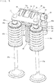
Fig. 5 is a perspective view which shows the valve gear and other components. -
Fig. 6 is a front view which shows the valve gear and other components. -
Fig. 7 is a side view which shows the valve gear and other components. -
Fig. 8 is a rear view which shows the valve gear and other components. -
Fig. 9 is a plan view which shows the valve gear and other components. -
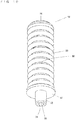
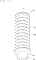
Fig. 10 is a perspective view which shows an example of a lost motion mechanism. -
Fig. 11 is a front view which shows an example of the lost motion mechanism. -
Fig. 12 is a sectional view which shows an example of the lost motion mechanism. -
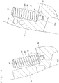
Fig. 13 is an illustrative drawing which shows the lost motion mechanism attached to the cylinder head. -
Fig. 14 is a sectional view which shows another example of the lost motion mechanism. -
Fig. 15 is a perspective view which shows yet another example of the lost motion mechanism. -
Fig. 16 is a perspective view which shows yet another example of the lost motion mechanism. -
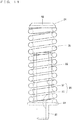
Fig. 17 is a front view which shows yet another example of the lost motion mechanism. -
Fig. 18 is a sectional view which shows another example of the lost motion mechanism. - Hereinafter, preferred embodiments of the present invention will be described with reference to the drawings.
- Referring to
Fig. 1 , anengine 10 according to a preferred embodiment of the present invention is installed in an automobile 1 and is used as a propelling source of the automobile 1. - Referring also to
Fig. 2 andFig. 3 , theengine 10 is a multi-cylinder engine which includes a plurality of cylinders, and in the present preferred embodiment is a straight four-cylinder engine. Theengine 10 includes a crankcase 12 which houses a crank shaft (not illustrated), acylinder block 14 connected with thecrank case 12, acylinder head 16 connected with thecylinder block 14, and acylinder head cover 18 attached to thecylinder head 16. - The
cylinder block 14 includes a plurality of cylinders located axially along a rocker shaft 58 (which will be described below). For each cylinder, acombustion chamber 22 is provided in thecylinder block 14 and thecylinder head 16. For eachcombustion chamber 22, thecylinder head 16 includes anintake port 20a and anexhaust port 20b. Theintake port 20a communicates with thecombustion chamber 22 via twoair inlets 24a, while theexhaust port 20b communicates with thecombustion chamber 22 via twoexhaust outlets 24b. - For each cylinder, the
cylinder head 16 is provided with twointake valves 26a and twoexhaust valves 26b assembled thereto. Eachintake valve 26a opens/closes a corresponding one of theair inlets 24a of theintake port 20a, while eachexhaust valve 26b opens/closes a corresponding one of theexhaust outlets 24b of theexhaust ports 20b. - The
intake valve 26a is slidably supported by thecylinder head 16 via acylindrical sleeve 28a. At an end of thesleeve 28a, on theintake valve 26a, avalve stem seal 30a is attached. Atappet 32a is fitted to a tip of theintake valve 26a. Avalve spring retainer 36a is fixed to theintake valve 26a via acotter 34a. Between thecylinder head 16 and thevalve spring retainer 36a, avalve spring 38a is provided to urge theintake valve 26a with a force (in upward direction inFig. 3 ) to close theair inlet 24a. Thevalve spring 38a is a compression coil spring. It should be noted here that theexhaust valve 26b and components nearby are the same as theintake valve 26a and those nearby. Therefore, theexhaust valve 26b and components nearby will not be described herein since they should be clear from the description given above by replacing the letter "a" of alphanumeric reference code of theintake valve 26a and other components with the letter "b". - The
cylinder head 16 rotatably supports anintake cam shaft 40a and anexhaust cam shaft 40b each extending axially along therocker shaft 58. Theintake cam shaft 40a is provided, for each cylinder, with an intake cam 42a which makes sliding contact with afirst arm portion 70 that will be described below, and twointake cams 44a which make sliding contact with asecond arm portion 72 that will be described below. Theexhaust cam shaft 40b is provided, for each cylinder, with an exhaust cam 42b which makes sliding contact with thefirst arm portion 70, and twoexhaust cams 44b which make sliding contact with thesecond arm portion 72. - The
cylinder head 16 is provided, for each cylinder, with avalve gear 46 for intake, and avalve gear 46 for exhaust. Thevalve gear 46 for intake receives a force from the intake cam 42a or theintake cam 44a, to open/close theintake valve 26a. Thevalve gear 46 for exhaust receives a force from the exhaust cam 42b or theexhaust cam 44b, to open/close theexhaust valve 26b. - The
cylinder head 16 is provided, for eachvalve gear 46 for intake, with afirst insertion hole 48a and asecond insertion hole 50a to attach thevalve gear 46, and for eachvalve gear 46 for exhaust, with afirst insertion hole 48b and asecond insertion hole 50b to attach thevalve gear 46. Also, thecylinder head 16 is provided, for eachvalve gear 46 for intake, with arecess 52a to attach a lost motion mechanism 68 (which will be described below), and for eachvalve gear 46 for exhaust, with arecess 52b to attach the lostmotion mechanism 68. - The
cylinder head 16 is provided, on the side where the valve gears 46 for intake are located, with afirst oil path 54a for connection-switching, and asecond oil path 56a for lubrication; and on the side where the valve gears 46 for exhaust are located, with afirst oil path 54b for connection-switching, and asecond oil path 56b for lubrication. Thefirst oil paths second oil paths cylinder head 16, with the upstream side being an upper side inFig. 2 and the downstream side being a lower side therein. - Hereinafter, description will cover the valve gears 46 on the intake side. The valve gears 46 on the exhaust side are configured the same way and can be easily understood, so that the duplicate description thereof will be omitted.
- Referring to
Fig. 4 through Fig. 9 , thevalve gear 46 includes therocker shaft 58. Therocker shaft 58 includes a first end region which is supported by afirst support 60a. Therocker shaft 58 includes a second end region which is supported by asecond support 60b. Therocker shaft 58 pivotably supports arocker arm 62 between thefirst support 60a and thesecond support 60b. Therocker shaft 58 and thefirst support 60a are connected with each other by a press-fit pin 64. In order to prevent thesecond support 60b from coming off therocker shaft 58, acirclip 66 is provided on the outer side of thesecond support 60b in therocker shaft 58. Also, thevalve gear 46 includes the lostmotion mechanism 68 which acts on therocker arm 62. - The
rocker arm 62 includes afirst arm portion 70 and asecond arm portion 72. - The
first arm portion 70 is pivotably supported by therocker shaft 58 and driven by the intake cam 42a. Thefirst arm portion 70 includes arotatable cam follower 74. Thesecond arm portion 72 is pivotably supported by therocker shaft 58 and drivable by theintake cam 44a. Further, thesecond arm portion 72 pivots to drive theintake valve 26a. Thesecond arm portion 72 includesrotatable cam followers second arm portion 72 has its center portion provided with arecess 78. In therecess 78, thefirst arm portion 70 is located. - An unillustrated switch is provided inside of the
first arm portion 70 and thesecond arm portion 72. The switch hydraulically slides a connecting pin (not illustrated) inside therocker arm 62, thus switching thefirst arm portion 70 and thesecond arm portion 72 between a connected state and a disconnected state. - In order to supply hydraulic pressure to the switch, a
third oil path 80 is provided which extends through thefirst support 60a, therocker shaft 58, and therocker arm 62 to the switch. Also, in order to lubricate areas between theintake cams 42a, 44a and therocker arm 62, afourth oil path 82 is provided which extends through thesecond support 60b and therocker shaft 58 to a region between therocker shaft 58 and therocker arm 62. - The
first support 60a, thesecond support 60b, therocker shaft 58, and therocker arm 62 described above are built into an assembly, which is then fixed onto thecylinder head 16 by inserting thefirst support 60a and thesecond support 60b into thefirst insertion hole 48a and thesecond insertion hole 50a respectively. Thus, in thefirst support 60a, thefirst oil path 54a and thethird oil path 80 communicate with each other. Also, in thesecond support 60b, thesecond oil path 56a and thefourth oil path 82 communicate with each other. - In the
valve gear 46, the switch brings thefirst arm portion 70 and thesecond arm portion 72 into the disconnected state if there is no connection-switching hydraulic pressure suppled from thethird oil path 80. In the disconnected state, thefirst arm portion 70 and thesecond arm portion 72 are pivotable independently from each other around therocker shaft 58 as a fulcrum point. On the intake side, as theintake cam shaft 40a rotates, the intake cam 42a presses thecam follower 74, which makes thefirst arm portion 70 pivot around therocker shaft 58; independently from this, as theintake cam shaft 40a rotates, the twointake cams 44a press the correspondingcam followers second arm portion 72 pivot around therocker shaft 58. Therefore, without being affected by the action of thefirst arm portion 70, thesecond arm portion 72 presses the twointake valves 26a such that the twoair inlets 24a of theintake port 20a are opened. - On the other hand, if there is a connection-switching hydraulic pressure suppled from the
third oil path 80, the switch brings thefirst arm portion 70 and thesecond arm portion 72 into the connected state. In the connected state, thefirst arm portion 70 and thesecond arm portion 72 become integrally pivotable around therocker shaft 58. On the intake side, as theintake cam shaft 40a rotates, the intake cam 42a presses thecam follower 74, which makes thefirst arm portion 70 and thesecond arm portion 72 pivot integrally with each other around therocker shaft 58. As a result, thesecond arm portion 72 presses the twointake valves 26a such that the twoair inlets 24a of theintake port 20a are opened. In this case, thesecond arm portion 72 moves theintake valve 26a by a lift amount (an amount the valve is opened), which is determined by an amount of pivot action of thefirst arm portion 70 that pivots integrally with thesecond arm portion 72. - Referring to
Fig. 10 through Fig. 12 , the lostmotion mechanism 68 includes aseat 84, apillar 86, aprotrusion 88, and a lostmotion spring 90. Theseat 84 has the shape of a hollow disc. Theseat 84 includes a first main surface provided with thepillar 86 which has ahollow portion 92, while theseat 84 includes a second main surface provided with thecylindrical protrusion 88. Theseat 84, thepillar 86, and theprotrusion 88 are coaxial with each other. Theseat 84, thepillar 86, and theprotrusion 88 are provided with a throughportion 94 which extends from a tip portion of theprotrusion 88 to thehollow portion 92 of thepillar 86. Therefore, thehollow portion 92 and the throughportion 94 define a through-hole 96 which penetrates theseat 84, thepillar 86, and theprotrusion 88. - The lost
motion spring 90 is a compression coil spring. Thepillar 86 is inserted into the lostmotion spring 90 until an end portion of the lostmotion spring 90 makes contact with theseat 84. Then, thepillar 86 extending axially of the lostmotion spring 90 limits bending of the lostmotion spring 90, and theseat 84 extending from thepillar 86 radially of the lostmotion spring 90 supports a lower end portion of the lostmotion spring 90. Theprotrusion 88 is located on an opposite side of theseat 84 from the lostmotion spring 90, and in this state, theprotrusion 88 does not project out of theseat 84 when viewed from an axial direction of the lostmotion spring 90. - Also, the lost
motion spring 90 has its upper end portion provided with alid 98. - The
protrusion 88 of the lostmotion mechanism 68 is attached to thecylinder head 16, i.e., a portion of theengine 10. By fitting theprotrusion 88 into therecess 52a of thecylinder head 16, theseat 84, i.e., the lostmotion mechanism 68, is attached to thecylinder head 16. When viewed from a longitudinal direction of thecylinder head 16, the lostmotion mechanism 68 is located between thefirst support 60a (thesecond support 60b) and theintake valve 26a (seeFig. 3 ). - The lost
motion spring 90 urges, via thelid 98, thefirst arm portion 70 of therocker arm 62 toward the intake cam 42a. As theintake cam shaft 40a rotates, the intake cam 42a repeats a cycle of pushing and not pushing thefirst arm portion 70 of therocker arm 62. When thefirst arm portion 70 is pushed downward, thefirst arm portion 70 pivots downward around the axial center of therocker shaft 58. In association with this, thefirst arm portion 70 pushes the lostmotion spring 90 via thelid 98, compressing the lostmotion spring 90. Thefirst arm portion 70 is constantly urged upward by the lostmotion spring 90. Therefore, when pushed by the intake cam 42a, thefirst arm portion 70 pivots against the spring force from the lostmotion spring 90. On the other hand, when the intake cam 42a does not push thefirst arm portion 70 downward, the lostmotion spring 90 stretches, and thefirst arm portion 70 is pivoted upward by the force from the lostmotion spring 90 around the axial center of therocker shaft 58. - In the present preferred embodiment, the
seat 84 corresponds to the support, thepillar 86 corresponds to the regulator, and theprotrusion 88 corresponds to the attaching portion. - Referring to
Fig. 3 andFig. 13 , according to theengine 10 which includes the lostmotion mechanism 68, theseat 84 is provided with theprotrusion 88 which corresponds to the attaching portion in order to attach theseat 84 which corresponds to the support to thecylinder head 16 which corresponds to the portion of theengine 10. It is possible to fix theseat 84, i.e., the lostmotion mechanism 68, to thecylinder head 16 by providing thecylinder head 16 with therecess 52a (52b) which is fittable to theprotrusion 88, and fitting theprotrusion 88 into therecess 52a (52b) of thecylinder head 16. Also, since theprotrusion 88 does not project out of theseat 84 when viewed from the axial direction of the lostmotion spring 90, it is possible to make theprotrusion 88 small and, accordingly, it is possible to make therecess 52a (52b) of thecylinder head 16 small, thus eliminating the need to increase the thickness of thecylinder head 16 where the lostmotion mechanism 68 is to be attached. - Since the
pillar 86 is inserted into the lostmotion spring 90, it is possible to decrease a radial dimension of the lostmotion mechanism 68, which makes it possible to miniaturize the lostmotion mechanism 68. - The
cylindrical protrusion 88 is provided on the opposite side of theseat 84 from the lostmotion spring 90. Therefore, it is possible to fix the lostmotion mechanism 68 to thecylinder head 16 only by providing thecylinder head 16 with therecess 52a (52b) which is fittable to thecylindrical protrusion 88, and fitting theprotrusion 88 into therecess 52a (52b) of thecylinder head 16. Also, since therecess 52a (52b) of thecylinder head 16 may be made as a small, columnar depression corresponding to thecylindrical protrusion 88, there is no need to increase the thickness of thecylinder head 16 where the lostmotion mechanism 68 is to be attached. - Since the
pillar 86 includes thehollow portion 92, it is possible to make thepillar 86 light weight. - The lost
motion mechanism 68 includes the through-hole 96 that penetrates thepillar 86, theseat 84, and theprotrusion 88. Therefore, even if a clearance between theprotrusion 88 of the lostmotion mechanism 68 and thecylinder head 16 is small, air and oil in the clearance easily escape through the through-hole 96, thus making it possible to reliably attach the lostmotion mechanism 68. - As described above, preferred embodiments of the present invention provide the
valve gear 46 and theengine 10 to which the lostmotion mechanism 68 can be fixed without increasing the thickness of thecylinder head 16 to which the lostmotion mechanism 68 is to be attached. -
Fig. 14 shows a lostmotion mechanism 68a as another example. - The lost
motion mechanism 68a differs from the lostmotion mechanism 68 in that it includes aseat 84a, apillar 86a, and apin 88a in place of theseat 84, thepillar 86, and theprotrusion 88. Theseat 84a has the shape of a hollow disc. Theseat 84a includes a first main surface provided with thepillar 86a which includes ahollow portion 92a. Theseat 84a and thepillar 86a include a throughportion 94a which extends from a second main surface of theseat 84a to thehollow portion 92a of thepillar 86a. Thepin 88a has a columnar shape, and is fitted into the throughportion 94a. In this state, a portion of thepin 88a protrudes from a lower main surface of theseat 84a, and this portion defines and functions as a columnar protrusion. Theseat 84a, thepillar 86a, and thepin 88a are coaxial with each other. Other features of the lostmotion mechanism 68a are the same as of the lostmotion mechanism 68. - According to the lost
motion mechanism 68a, thepin 88a includes a portion which functions as the columnar protrusion, and this portion is on the opposite side of theseat 84a from the lostmotion spring 90. Therefore, it is possible to fix the lostmotion mechanism 68a to thecylinder head 16 only by providing thecylinder head 16 with therecess 52a (52b) which is fittable to the columnar protrusion, and fitting the columnar protrusion into therecess 52a (52b) of thecylinder head 16. Also, since therecess 52a (52b) of thecylinder head 16 may be made as a small, columnar depression corresponding to the columnar protrusion, there is no need to increase the thickness of thecylinder head 16 where the lostmotion mechanism 68a is to be attached. -
Fig. 15 shows a lost motion mechanism 68b as another example. - The lost motion mechanism 68b differs from the lost
motion mechanism 68 in that it includes aseat 84b, apillar 86b, and a protrusion 88b in place of theseat 84, thepillar 86, and theprotrusion 88, and that it does not include the throughportion 94. Theseat 84b has the shape of a disc. Theseat 84b includes a first main surface provided with thepillar 86b which includes a hollow portion (not illustrated), while theseat 84b includes a second main surface provided with the protrusion 88b which is plate-shaped. Other features of the lost motion mechanism 68b are the same as of the lostmotion mechanism 68. - In order to attach the protrusion 88b of the lost motion mechanism 68b to a cylinder head, the cylinder head is provided with a recess fittable to the protrusion 88b. Then, by fitting the protrusion 88b into the recess of the cylinder head, the lost motion mechanism 68b is attached to the cylinder head.
- According to the lost motion mechanism 68b, the plate-shaped protrusion 88b is provided on the opposite side of the
seat 84b from the lostmotion spring 90. Therefore, it is possible to fix the lost motion mechanism 68b to the cylinder head only by providing the cylinder head with the recess which is fittable to the plate-like protrusion 88b, and fitting the protrusion 88b into the recess of the cylinder head. Also, the recess of the cylinder head may be a depression having a narrow and elongated section corresponding to the plate-shaped protrusion 88b. Therefore, it is possible to attach the lost motion mechanism 68b even to a narrow area of the cylinder head. -
Fig. 16 shows a lostmotion mechanism 68c as yet another example. - The lost
motion mechanism 68c differs from the lost motion mechanism 68b in that it includes aprotrusion 88c which has a cross-shaped section, in place of the protrusion 88b. Other features of the lostmotion mechanism 68c are the same as of the lost motion mechanism 68b. - In order to attach the
protrusion 88c of the lostmotion mechanism 68c to a cylinder head, the cylinder head is provided with a recess having a cross-shaped section. Then, by fitting theprotrusion 88c into the recess of the cylinder head, the lostmotion mechanism 68c is attached to the cylinder head. - According to the lost
motion mechanism 68c, theprotrusion 88c having a cross-shaped section is provided on the opposite side of theseat 84b from the lostmotion spring 90. Therefore, it is possible to fix the lostmotion mechanism 68c to the cylinder head reliably by providing the cylinder head with the recess which is fittable to theprotrusion 88c which has the cross-shaped section, and fitting theprotrusion 88c into the recess of the cylinder head. -
Fig. 17 andFig. 18 show alost motion mechanism 68d as yet another example. - The lost
motion mechanism 68d differs from the lostmotion mechanism 68 in that it includes acylindrical member 86d and a throughportion 94d in place of thepillar 86 and the throughportion 94. Thecylindrical member 86d functions as the regulator, includes ahollow portion 92d, and is provided on theseat 84 so as to cover (surround) the lostmotion spring 90. Theseat 84 and theprotrusion 88 include a throughportion 94d which extends from a tip portion of theprotrusion 88 to thehollow portion 92d of thecylindrical member 86d. Therefore, thehollow portion 92d and the throughportion 94d define a through-hole 96d which penetrates theseat 84, thecylindrical member 86d, and theprotrusion 88. In the lostmotion mechanism 68d, the lostmotion spring 90 is inserted into thecylindrical member 86d until an end portion of the lostmotion spring 90 makes contact with theseat 84. Other features of the lostmotion mechanism 68d are the same as of the lostmotion mechanism 68. - According to the lost
motion mechanism 68d, thecylindrical member 86d covers (surrounds) the lostmotion spring 90, and therefore it is possible to protect the lostmotion spring 90 by thecylindrical member 86d, and to effectively limit the bending of the lostmotion spring 90. - In the preferred embodiments described above, the attaching portion provided in the support is a protrusion. However, preferred embodiments of the present invention are not limited to this. For example, the attaching portion may be a recess. In this case, the cylinder head is provided with a protrusion that fits into the recess. Also, the attaching portion may include both a protrusion and a recess. In this case, the cylinder head is provided with a recess and a protrusion to fit around the protrusion and into the recess, respectively.
- In the preferred embodiments described above, the support (the seat) is located on a lower side and the lid is located on an upper side when the lost motion mechanism is provided in cylinder head. However, preferred embodiments of the present invention are not limited to this. For example, the lost motion mechanism may be provided in a different portion of the engine other than the cylinder head. Also, there may be an arrangement that the support is located on the upper side, the lid is located on the lower side, and the support makes contact with an upper end portion of the lost motion spring when the lost motion mechanism is provided in the portion of the engine.
- The preferred embodiments described thus far change the valve lift amount depending on whether or not the
first arm portion 70 and thesecond arm portion 72 are connected with each other. However, preferred embodiments of the present invention are not limited to this. For example, whether or not thefirst arm portion 70 and thesecond arm portion 72 are connected with each other may determine whether or not the valve is brought to an inactive state. - In the preferred embodiments described above, the
engine 10 is a multi-cylinder engine. However, preferred embodiments of the present invention are not limited to this. Preferred embodiments of the present invention may also be applied to a single-cylinder engine. - The engine according to preferred embodiments of the present invention may also be suitably installed in vehicles such as motorcycles, auto-tricycles, and ATVs (All Terrain Vehicles) as well as outboard engines, and others.
- While preferred embodiments of the present invention have been described above, it is to be understood that variations and modifications will be apparent to those skilled in the art without departing from the scope and spirit of the present invention. The scope of the present invention, therefore, is to be determined solely by the following claims.
Claims (11)
- A lost motion mechanism (68, 68a - 68d) for an engine (10), the lost motion mechanism (68, 68a - 68d) comprising:a lost motion spring (90);a regulator extending in an axial direction of the lost motion spring (90) to limit bending of the lost motion spring (90) ;a support extending radially of the lost motion spring (90) from the regulator to make contact with an end portion of the lost motion spring (90); andan attaching portion including at least a protrusion (88, 88a, 88b, 88c) or a recess provided on the support to attach the support to the engine (10); whereinthe attaching portion does not project out of the support when viewed from the axial direction.
- The lost motion mechanism (68, 68a - 68d) according to Claim 1, wherein
the support includes a seat (84, 84a, 84b) to support a lower end portion of the lost motion spring (90);
the attaching portion (88) is located in the seat (84, 84a, 84b); and
the engine (10) includes a cylinder head (16) to which the attaching portion (84) is to be attached. - The lost motion mechanism (68, 68a - 68c) according to Claim 1 or 2, wherein the regulator includes a pillar (86, 86a, 86b) inserted into the lost motion spring (90).
- The lost motion mechanism (68d) according to Claim 1 or 2, wherein the regulator includes a cylindrical cover (86d) to cover the lost motion spring (90).
- The lost motion mechanism (68, 68a, 68d) according to one of Claims 1 to 4, wherein the protrusion (88, 88a) of the attaching portion has a columnar or cylindrical shape, and is located on an opposite side of the support from the lost motion spring (90).
- The lost motion mechanism (68b) according to one of Claims 1 to 5, wherein the protrusion (88b) of the attaching portion is plate-shaped and is located on an opposite side of the support from the lost motion spring (90).
- The lost motion mechanism (68c) according to one of Claims 1 to 5, wherein the protrusion (88c) of the attaching portion has a cross-shaped section and is located on an opposite side of the support from the lost motion spring (90).
- The lost motion mechanism (68, 68a - 68c) according to Claim 3, wherein the pillar (86, 86a, 86b) includes a hollow portion (92, 92a).
- The lost motion mechanism (68, 68d) according to one of Claims 1 to 5 and 8, further comprising a through-hole (96, 96d) that extends through the regulator, the support, and the attaching portion.
- A valve gear (46) comprising:
the lost motion mechanism (68, 68a - 68d) according to one of Claims 1 to 9. - An engine (10) comprising:
the valve gear (46) according to Claim 10.
Applications Claiming Priority (1)
| Application Number | Priority Date | Filing Date | Title |
|---|---|---|---|
| JP2019239845A JP6932179B2 (en) | 2019-12-27 | 2019-12-27 | Lost motion mechanism, valve gear and engine |
Publications (2)
| Publication Number | Publication Date |
|---|---|
| EP3842623A1 true EP3842623A1 (en) | 2021-06-30 |
| EP3842623B1 EP3842623B1 (en) | 2023-02-08 |
Family
ID=73856740
Family Applications (1)
| Application Number | Title | Priority Date | Filing Date |
|---|---|---|---|
| EP20216365.5A Active EP3842623B1 (en) | 2019-12-27 | 2020-12-22 | Lost motion mechanism, valve gear and engine |
Country Status (3)
| Country | Link |
|---|---|
| US (1) | US11193401B2 (en) |
| EP (1) | EP3842623B1 (en) |
| JP (1) | JP6932179B2 (en) |
Citations (6)
| Publication number | Priority date | Publication date | Assignee | Title |
|---|---|---|---|---|
| FR1594168A (en) * | 1967-12-07 | 1970-06-01 | ||
| DE10112980A1 (en) * | 2001-03-17 | 2002-09-19 | Ina Schaeffler Kg | Valve gear for internal combustion engine has support element as rod extending by end furthest from cam directly into recess in engine, and outside engine is encompassed by compression spring acting on stop in contact with cam follower |
| EP1712748A1 (en) * | 2005-01-12 | 2006-10-18 | Eaton S.R.L. | Rocker arm arrangement for dual valve timing with single cam lobe |
| US20130042830A1 (en) * | 2010-04-07 | 2013-02-21 | Toyota Jidosha Kabushiki Kaisha | Valve operating apparatus for internal combustion engine |
| JP2016094901A (en) | 2014-11-14 | 2016-05-26 | トヨタ自動車株式会社 | Variable valve device |
| US20190301312A1 (en) * | 2016-07-14 | 2019-10-03 | Thyssenkrupp Presta Teccenter Ag | Assembly aid, camshaft module, and method for fixing the rotational position of rotatably mounted shafts |
Family Cites Families (13)
| Publication number | Priority date | Publication date | Assignee | Title |
|---|---|---|---|---|
| JPH03267514A (en) | 1990-03-19 | 1991-11-28 | Nissan Motor Co Ltd | Valve operating device of engine |
| KR950005088B1 (en) * | 1990-07-10 | 1995-05-18 | 미쯔비시 지도샤 고교 가부시끼가이샤 | Automotive power valve device |
| JP2001329817A (en) | 2000-05-19 | 2001-11-30 | Otics Corp | Variable valve mechanism |
| JP4476241B2 (en) * | 2005-06-20 | 2010-06-09 | 日立オートモティブシステムズ株式会社 | Valve operating device for internal combustion engine |
| JP4931680B2 (en) | 2007-04-19 | 2012-05-16 | 株式会社オティックス | Valve mechanism |
| JP5049089B2 (en) | 2007-10-05 | 2012-10-17 | 株式会社オティックス | Rocker arm support member and variable valve mechanism |
| KR100980872B1 (en) * | 2007-12-14 | 2010-09-14 | 현대자동차주식회사 | Variable valve lift device |
| JP5139112B2 (en) | 2008-02-19 | 2013-02-06 | ヤマハ発動機株式会社 | engine |
| JP2009264200A (en) | 2008-04-23 | 2009-11-12 | Honda Motor Co Ltd | Variable valve gear |
| WO2011024335A1 (en) | 2009-08-24 | 2011-03-03 | ヤマハ発動機株式会社 | Variable valve device, engine with same, and saddled vehicle |
| EP3203044B1 (en) * | 2014-10-03 | 2019-12-04 | Yamaha Hatsudoki Kabushiki Kaisha | Valve gear for engine and method for producing rocker arm |
| JP6220987B2 (en) | 2014-10-03 | 2017-10-25 | ヤマハ発動機株式会社 | Engine valve gear |
| JP6458090B2 (en) | 2017-06-30 | 2019-01-23 | ヤマハ発動機株式会社 | Internal combustion engine and vehicle |
-
2019
- 2019-12-27 JP JP2019239845A patent/JP6932179B2/en active Active
-
2020
- 2020-12-08 US US17/114,560 patent/US11193401B2/en active Active
- 2020-12-22 EP EP20216365.5A patent/EP3842623B1/en active Active
Patent Citations (6)
| Publication number | Priority date | Publication date | Assignee | Title |
|---|---|---|---|---|
| FR1594168A (en) * | 1967-12-07 | 1970-06-01 | ||
| DE10112980A1 (en) * | 2001-03-17 | 2002-09-19 | Ina Schaeffler Kg | Valve gear for internal combustion engine has support element as rod extending by end furthest from cam directly into recess in engine, and outside engine is encompassed by compression spring acting on stop in contact with cam follower |
| EP1712748A1 (en) * | 2005-01-12 | 2006-10-18 | Eaton S.R.L. | Rocker arm arrangement for dual valve timing with single cam lobe |
| US20130042830A1 (en) * | 2010-04-07 | 2013-02-21 | Toyota Jidosha Kabushiki Kaisha | Valve operating apparatus for internal combustion engine |
| JP2016094901A (en) | 2014-11-14 | 2016-05-26 | トヨタ自動車株式会社 | Variable valve device |
| US20190301312A1 (en) * | 2016-07-14 | 2019-10-03 | Thyssenkrupp Presta Teccenter Ag | Assembly aid, camshaft module, and method for fixing the rotational position of rotatably mounted shafts |
Also Published As
| Publication number | Publication date |
|---|---|
| JP2021107706A (en) | 2021-07-29 |
| EP3842623B1 (en) | 2023-02-08 |
| US20210199028A1 (en) | 2021-07-01 |
| JP6932179B2 (en) | 2021-09-08 |
| US11193401B2 (en) | 2021-12-07 |
Similar Documents
| Publication | Publication Date | Title |
|---|---|---|
| US5960754A (en) | Valve operating system in internal combustion engine | |
| US20090095241A1 (en) | Cam follower for the variable actuation of a gas-exchange valve of an internal combustion engine | |
| AU2013201996B2 (en) | Variable valve gear for internal combustion engine | |
| EP0396327B1 (en) | Valve operating system of internal combustion engine | |
| EP3845743B1 (en) | Valve gear and engine | |
| EP2211031B1 (en) | Air spring with cap | |
| EP3647557B1 (en) | Internal combustion engine and vehicle | |
| US11193401B2 (en) | Lost motion mechanism, valve gear and engine | |
| US7584733B2 (en) | Mounting structure of ignition plug tube | |
| EP3203044B1 (en) | Valve gear for engine and method for producing rocker arm | |
| EP3156618A1 (en) | Engine | |
| US6732693B2 (en) | Valve-operating assembly of driven rotation member and cam | |
| US11591939B2 (en) | Compression release mechanism and internal combustion engine including the same | |
| US6880507B2 (en) | Internal combustion engine with switchable cam follower | |
| US10584620B2 (en) | Lubrication of backs of cams by oil recovery | |
| EP3647555B1 (en) | Internal combustion engine and vehicle | |
| US10697331B2 (en) | Valve actuating mechanism having combined bearing and hydraulic lash adjuster retention device | |
| US6899065B2 (en) | Radial-valve gear apparatus for barrel engine | |
| EP1013898B1 (en) | Valve operating system in internal combustion engine | |
| US6725820B2 (en) | Valve-operating mechanism in engine |
Legal Events
| Date | Code | Title | Description |
|---|---|---|---|
| PUAI | Public reference made under article 153(3) epc to a published international application that has entered the european phase |
Free format text: ORIGINAL CODE: 0009012 |
|
| STAA | Information on the status of an ep patent application or granted ep patent |
Free format text: STATUS: THE APPLICATION HAS BEEN PUBLISHED |
|
| AK | Designated contracting states |
Kind code of ref document: A1 Designated state(s): AL AT BE BG CH CY CZ DE DK EE ES FI FR GB GR HR HU IE IS IT LI LT LU LV MC MK MT NL NO PL PT RO RS SE SI SK SM TR |
|
| STAA | Information on the status of an ep patent application or granted ep patent |
Free format text: STATUS: REQUEST FOR EXAMINATION WAS MADE |
|
| 17P | Request for examination filed |
Effective date: 20211104 |
|
| RBV | Designated contracting states (corrected) |
Designated state(s): AL AT BE BG CH CY CZ DE DK EE ES FI FR GB GR HR HU IE IS IT LI LT LU LV MC MK MT NL NO PL PT RO RS SE SI SK SM TR |
|
| STAA | Information on the status of an ep patent application or granted ep patent |
Free format text: STATUS: EXAMINATION IS IN PROGRESS |
|
| 17Q | First examination report despatched |
Effective date: 20220121 |
|
| GRAP | Despatch of communication of intention to grant a patent |
Free format text: ORIGINAL CODE: EPIDOSNIGR1 |
|
| STAA | Information on the status of an ep patent application or granted ep patent |
Free format text: STATUS: GRANT OF PATENT IS INTENDED |
|
| RIC1 | Information provided on ipc code assigned before grant |
Ipc: F01L 1/46 20060101ALN20220622BHEP Ipc: F01L 1/053 20060101ALN20220622BHEP Ipc: F01L 1/18 20060101ALN20220622BHEP Ipc: F01L 13/00 20060101ALI20220622BHEP Ipc: F01L 1/26 20060101AFI20220622BHEP |
|
| INTG | Intention to grant announced |
Effective date: 20220712 |
|
| GRAS | Grant fee paid |
Free format text: ORIGINAL CODE: EPIDOSNIGR3 |
|
| GRAA | (expected) grant |
Free format text: ORIGINAL CODE: 0009210 |
|
| STAA | Information on the status of an ep patent application or granted ep patent |
Free format text: STATUS: THE PATENT HAS BEEN GRANTED |
|
| AK | Designated contracting states |
Kind code of ref document: B1 Designated state(s): AL AT BE BG CH CY CZ DE DK EE ES FI FR GB GR HR HU IE IS IT LI LT LU LV MC MK MT NL NO PL PT RO RS SE SI SK SM TR |
|
| REG | Reference to a national code |
Ref country code: GB Ref legal event code: FG4D |
|
| REG | Reference to a national code |
Ref country code: CH Ref legal event code: EP Ref country code: AT Ref legal event code: REF Ref document number: 1547526 Country of ref document: AT Kind code of ref document: T Effective date: 20230215 |
|
| REG | Reference to a national code |
Ref country code: IE Ref legal event code: FG4D |
|
| REG | Reference to a national code |
Ref country code: DE Ref legal event code: R096 Ref document number: 602020007990 Country of ref document: DE |
|
| REG | Reference to a national code |
Ref country code: LT Ref legal event code: MG9D |
|
| REG | Reference to a national code |
Ref country code: NL Ref legal event code: MP Effective date: 20230208 |
|
| REG | Reference to a national code |
Ref country code: AT Ref legal event code: MK05 Ref document number: 1547526 Country of ref document: AT Kind code of ref document: T Effective date: 20230208 |
|
| PG25 | Lapsed in a contracting state [announced via postgrant information from national office to epo] |
Ref country code: RS Free format text: LAPSE BECAUSE OF FAILURE TO SUBMIT A TRANSLATION OF THE DESCRIPTION OR TO PAY THE FEE WITHIN THE PRESCRIBED TIME-LIMIT Effective date: 20230208 Ref country code: PT Free format text: LAPSE BECAUSE OF FAILURE TO SUBMIT A TRANSLATION OF THE DESCRIPTION OR TO PAY THE FEE WITHIN THE PRESCRIBED TIME-LIMIT Effective date: 20230609 Ref country code: NO Free format text: LAPSE BECAUSE OF FAILURE TO SUBMIT A TRANSLATION OF THE DESCRIPTION OR TO PAY THE FEE WITHIN THE PRESCRIBED TIME-LIMIT Effective date: 20230508 Ref country code: NL Free format text: LAPSE BECAUSE OF FAILURE TO SUBMIT A TRANSLATION OF THE DESCRIPTION OR TO PAY THE FEE WITHIN THE PRESCRIBED TIME-LIMIT Effective date: 20230208 Ref country code: LV Free format text: LAPSE BECAUSE OF FAILURE TO SUBMIT A TRANSLATION OF THE DESCRIPTION OR TO PAY THE FEE WITHIN THE PRESCRIBED TIME-LIMIT Effective date: 20230208 Ref country code: LT Free format text: LAPSE BECAUSE OF FAILURE TO SUBMIT A TRANSLATION OF THE DESCRIPTION OR TO PAY THE FEE WITHIN THE PRESCRIBED TIME-LIMIT Effective date: 20230208 Ref country code: HR Free format text: LAPSE BECAUSE OF FAILURE TO SUBMIT A TRANSLATION OF THE DESCRIPTION OR TO PAY THE FEE WITHIN THE PRESCRIBED TIME-LIMIT Effective date: 20230208 Ref country code: ES Free format text: LAPSE BECAUSE OF FAILURE TO SUBMIT A TRANSLATION OF THE DESCRIPTION OR TO PAY THE FEE WITHIN THE PRESCRIBED TIME-LIMIT Effective date: 20230208 Ref country code: AT Free format text: LAPSE BECAUSE OF FAILURE TO SUBMIT A TRANSLATION OF THE DESCRIPTION OR TO PAY THE FEE WITHIN THE PRESCRIBED TIME-LIMIT Effective date: 20230208 |
|
| PG25 | Lapsed in a contracting state [announced via postgrant information from national office to epo] |
Ref country code: SE Free format text: LAPSE BECAUSE OF FAILURE TO SUBMIT A TRANSLATION OF THE DESCRIPTION OR TO PAY THE FEE WITHIN THE PRESCRIBED TIME-LIMIT Effective date: 20230208 Ref country code: PL Free format text: LAPSE BECAUSE OF FAILURE TO SUBMIT A TRANSLATION OF THE DESCRIPTION OR TO PAY THE FEE WITHIN THE PRESCRIBED TIME-LIMIT Effective date: 20230208 Ref country code: IS Free format text: LAPSE BECAUSE OF FAILURE TO SUBMIT A TRANSLATION OF THE DESCRIPTION OR TO PAY THE FEE WITHIN THE PRESCRIBED TIME-LIMIT Effective date: 20230608 Ref country code: GR Free format text: LAPSE BECAUSE OF FAILURE TO SUBMIT A TRANSLATION OF THE DESCRIPTION OR TO PAY THE FEE WITHIN THE PRESCRIBED TIME-LIMIT Effective date: 20230509 Ref country code: FI Free format text: LAPSE BECAUSE OF FAILURE TO SUBMIT A TRANSLATION OF THE DESCRIPTION OR TO PAY THE FEE WITHIN THE PRESCRIBED TIME-LIMIT Effective date: 20230208 |
|
| PG25 | Lapsed in a contracting state [announced via postgrant information from national office to epo] |
Ref country code: SM Free format text: LAPSE BECAUSE OF FAILURE TO SUBMIT A TRANSLATION OF THE DESCRIPTION OR TO PAY THE FEE WITHIN THE PRESCRIBED TIME-LIMIT Effective date: 20230208 Ref country code: RO Free format text: LAPSE BECAUSE OF FAILURE TO SUBMIT A TRANSLATION OF THE DESCRIPTION OR TO PAY THE FEE WITHIN THE PRESCRIBED TIME-LIMIT Effective date: 20230208 Ref country code: EE Free format text: LAPSE BECAUSE OF FAILURE TO SUBMIT A TRANSLATION OF THE DESCRIPTION OR TO PAY THE FEE WITHIN THE PRESCRIBED TIME-LIMIT Effective date: 20230208 Ref country code: DK Free format text: LAPSE BECAUSE OF FAILURE TO SUBMIT A TRANSLATION OF THE DESCRIPTION OR TO PAY THE FEE WITHIN THE PRESCRIBED TIME-LIMIT Effective date: 20230208 Ref country code: CZ Free format text: LAPSE BECAUSE OF FAILURE TO SUBMIT A TRANSLATION OF THE DESCRIPTION OR TO PAY THE FEE WITHIN THE PRESCRIBED TIME-LIMIT Effective date: 20230208 |
|
| REG | Reference to a national code |
Ref country code: DE Ref legal event code: R097 Ref document number: 602020007990 Country of ref document: DE |
|
| PG25 | Lapsed in a contracting state [announced via postgrant information from national office to epo] |
Ref country code: SK Free format text: LAPSE BECAUSE OF FAILURE TO SUBMIT A TRANSLATION OF THE DESCRIPTION OR TO PAY THE FEE WITHIN THE PRESCRIBED TIME-LIMIT Effective date: 20230208 |
|
| PLBE | No opposition filed within time limit |
Free format text: ORIGINAL CODE: 0009261 |
|
| STAA | Information on the status of an ep patent application or granted ep patent |
Free format text: STATUS: NO OPPOSITION FILED WITHIN TIME LIMIT |
|
| 26N | No opposition filed |
Effective date: 20231109 |
|
| PG25 | Lapsed in a contracting state [announced via postgrant information from national office to epo] |
Ref country code: SI Free format text: LAPSE BECAUSE OF FAILURE TO SUBMIT A TRANSLATION OF THE DESCRIPTION OR TO PAY THE FEE WITHIN THE PRESCRIBED TIME-LIMIT Effective date: 20230208 |
|
| REG | Reference to a national code |
Ref country code: CH Ref legal event code: PL |
|
| PG25 | Lapsed in a contracting state [announced via postgrant information from national office to epo] |
Ref country code: LU Free format text: LAPSE BECAUSE OF NON-PAYMENT OF DUE FEES Effective date: 20231222 |
|
| PG25 | Lapsed in a contracting state [announced via postgrant information from national office to epo] |
Ref country code: MC Free format text: LAPSE BECAUSE OF FAILURE TO SUBMIT A TRANSLATION OF THE DESCRIPTION OR TO PAY THE FEE WITHIN THE PRESCRIBED TIME-LIMIT Effective date: 20230208 |
|
| REG | Reference to a national code |
Ref country code: BE Ref legal event code: MM Effective date: 20231231 |
|
| PG25 | Lapsed in a contracting state [announced via postgrant information from national office to epo] |
Ref country code: MC Free format text: LAPSE BECAUSE OF FAILURE TO SUBMIT A TRANSLATION OF THE DESCRIPTION OR TO PAY THE FEE WITHIN THE PRESCRIBED TIME-LIMIT Effective date: 20230208 Ref country code: LU Free format text: LAPSE BECAUSE OF NON-PAYMENT OF DUE FEES Effective date: 20231222 |
|
| REG | Reference to a national code |
Ref country code: IE Ref legal event code: MM4A |
|
| PG25 | Lapsed in a contracting state [announced via postgrant information from national office to epo] |
Ref country code: IE Free format text: LAPSE BECAUSE OF NON-PAYMENT OF DUE FEES Effective date: 20231222 |
|
| PG25 | Lapsed in a contracting state [announced via postgrant information from national office to epo] |
Ref country code: BE Free format text: LAPSE BECAUSE OF NON-PAYMENT OF DUE FEES Effective date: 20231231 |
|
| PG25 | Lapsed in a contracting state [announced via postgrant information from national office to epo] |
Ref country code: CH Free format text: LAPSE BECAUSE OF NON-PAYMENT OF DUE FEES Effective date: 20231231 |
|
| PG25 | Lapsed in a contracting state [announced via postgrant information from national office to epo] |
Ref country code: IE Free format text: LAPSE BECAUSE OF NON-PAYMENT OF DUE FEES Effective date: 20231222 Ref country code: CH Free format text: LAPSE BECAUSE OF NON-PAYMENT OF DUE FEES Effective date: 20231231 Ref country code: BE Free format text: LAPSE BECAUSE OF NON-PAYMENT OF DUE FEES Effective date: 20231231 |
|
| PG25 | Lapsed in a contracting state [announced via postgrant information from national office to epo] |
Ref country code: BG Free format text: LAPSE BECAUSE OF FAILURE TO SUBMIT A TRANSLATION OF THE DESCRIPTION OR TO PAY THE FEE WITHIN THE PRESCRIBED TIME-LIMIT Effective date: 20230208 |
|
| PG25 | Lapsed in a contracting state [announced via postgrant information from national office to epo] |
Ref country code: BG Free format text: LAPSE BECAUSE OF FAILURE TO SUBMIT A TRANSLATION OF THE DESCRIPTION OR TO PAY THE FEE WITHIN THE PRESCRIBED TIME-LIMIT Effective date: 20230208 |
|
| PG25 | Lapsed in a contracting state [announced via postgrant information from national office to epo] |
Ref country code: CY Free format text: LAPSE BECAUSE OF FAILURE TO SUBMIT A TRANSLATION OF THE DESCRIPTION OR TO PAY THE FEE WITHIN THE PRESCRIBED TIME-LIMIT; INVALID AB INITIO Effective date: 20201222 |
|
| PG25 | Lapsed in a contracting state [announced via postgrant information from national office to epo] |
Ref country code: HU Free format text: LAPSE BECAUSE OF FAILURE TO SUBMIT A TRANSLATION OF THE DESCRIPTION OR TO PAY THE FEE WITHIN THE PRESCRIBED TIME-LIMIT; INVALID AB INITIO Effective date: 20201222 |
|
| PG25 | Lapsed in a contracting state [announced via postgrant information from national office to epo] |
Ref country code: TR Free format text: LAPSE BECAUSE OF FAILURE TO SUBMIT A TRANSLATION OF THE DESCRIPTION OR TO PAY THE FEE WITHIN THE PRESCRIBED TIME-LIMIT Effective date: 20230208 |
|
| PGFP | Annual fee paid to national office [announced via postgrant information from national office to epo] |
Ref country code: DE Payment date: 20251211 Year of fee payment: 6 |
|
| PGFP | Annual fee paid to national office [announced via postgrant information from national office to epo] |
Ref country code: GB Payment date: 20251219 Year of fee payment: 6 |
|
| PGFP | Annual fee paid to national office [announced via postgrant information from national office to epo] |
Ref country code: IT Payment date: 20251223 Year of fee payment: 6 |
|
| PGFP | Annual fee paid to national office [announced via postgrant information from national office to epo] |
Ref country code: FR Payment date: 20251229 Year of fee payment: 6 |