EP3842594A1 - Construction machine - Google Patents
Construction machine Download PDFInfo
- Publication number
- EP3842594A1 EP3842594A1 EP19851785.6A EP19851785A EP3842594A1 EP 3842594 A1 EP3842594 A1 EP 3842594A1 EP 19851785 A EP19851785 A EP 19851785A EP 3842594 A1 EP3842594 A1 EP 3842594A1
- Authority
- EP
- European Patent Office
- Prior art keywords
- torque
- gravity
- turning
- angular acceleration
- calculation unit
- Prior art date
- Legal status (The legal status is an assumption and is not a legal conclusion. Google has not performed a legal analysis and makes no representation as to the accuracy of the status listed.)
- Granted
Links
Images



Classifications
-
- E—FIXED CONSTRUCTIONS
- E02—HYDRAULIC ENGINEERING; FOUNDATIONS; SOIL SHIFTING
- E02F—DREDGING; SOIL-SHIFTING
- E02F9/00—Component parts of dredgers or soil-shifting machines, not restricted to one of the kinds covered by groups E02F3/00 - E02F7/00
- E02F9/08—Superstructures; Supports for superstructures
- E02F9/10—Supports for movable superstructures mounted on travelling or walking gears or on other superstructures
- E02F9/12—Slewing or traversing gears
- E02F9/121—Turntables, i.e. structure rotatable about 360°
- E02F9/123—Drives or control devices specially adapted therefor
-
- E—FIXED CONSTRUCTIONS
- E02—HYDRAULIC ENGINEERING; FOUNDATIONS; SOIL SHIFTING
- E02F—DREDGING; SOIL-SHIFTING
- E02F3/00—Dredgers; Soil-shifting machines
- E02F3/04—Dredgers; Soil-shifting machines mechanically-driven
- E02F3/28—Dredgers; Soil-shifting machines mechanically-driven with digging tools mounted on a dipper- or bucket-arm, i.e. there is either one arm or a pair of arms, e.g. dippers, buckets
- E02F3/30—Dredgers; Soil-shifting machines mechanically-driven with digging tools mounted on a dipper- or bucket-arm, i.e. there is either one arm or a pair of arms, e.g. dippers, buckets with a dipper-arm pivoted on a cantilever beam, i.e. boom
- E02F3/32—Dredgers; Soil-shifting machines mechanically-driven with digging tools mounted on a dipper- or bucket-arm, i.e. there is either one arm or a pair of arms, e.g. dippers, buckets with a dipper-arm pivoted on a cantilever beam, i.e. boom working downwardly and towards the machine, e.g. with backhoes
- E02F3/325—Backhoes of the miniature type
-
- E—FIXED CONSTRUCTIONS
- E02—HYDRAULIC ENGINEERING; FOUNDATIONS; SOIL SHIFTING
- E02F—DREDGING; SOIL-SHIFTING
- E02F3/00—Dredgers; Soil-shifting machines
- E02F3/04—Dredgers; Soil-shifting machines mechanically-driven
- E02F3/28—Dredgers; Soil-shifting machines mechanically-driven with digging tools mounted on a dipper- or bucket-arm, i.e. there is either one arm or a pair of arms, e.g. dippers, buckets
- E02F3/36—Component parts
- E02F3/42—Drives for dippers, buckets, dipper-arms or bucket-arms
- E02F3/43—Control of dipper or bucket position; Control of sequence of drive operations
- E02F3/435—Control of dipper or bucket position; Control of sequence of drive operations for dipper-arms, backhoes or the like
-
- E—FIXED CONSTRUCTIONS
- E02—HYDRAULIC ENGINEERING; FOUNDATIONS; SOIL SHIFTING
- E02F—DREDGING; SOIL-SHIFTING
- E02F9/00—Component parts of dredgers or soil-shifting machines, not restricted to one of the kinds covered by groups E02F3/00 - E02F7/00
- E02F9/20—Drives; Control devices
- E02F9/2004—Control mechanisms, e.g. control levers
-
- E—FIXED CONSTRUCTIONS
- E02—HYDRAULIC ENGINEERING; FOUNDATIONS; SOIL SHIFTING
- E02F—DREDGING; SOIL-SHIFTING
- E02F9/00—Component parts of dredgers or soil-shifting machines, not restricted to one of the kinds covered by groups E02F3/00 - E02F7/00
- E02F9/20—Drives; Control devices
- E02F9/2058—Electric or electro-mechanical or mechanical control devices of vehicle sub-units
-
- G—PHYSICS
- G06—COMPUTING OR CALCULATING; COUNTING
- G06N—COMPUTING ARRANGEMENTS BASED ON SPECIFIC COMPUTATIONAL MODELS
- G06N20/00—Machine learning
-
- G—PHYSICS
- G06—COMPUTING OR CALCULATING; COUNTING
- G06N—COMPUTING ARRANGEMENTS BASED ON SPECIFIC COMPUTATIONAL MODELS
- G06N5/00—Computing arrangements using knowledge-based models
- G06N5/04—Inference or reasoning models
Definitions
- the present disclosure relates to a construction machine that turns by means of an electric turning motor.
- an upper turning body is equipped with a work machine, such as a boom and an arm.
- a work machine has a large weight, and the moment of inertia of the upper turning body differs depending on whether the boom or the arm is in an extended state or a contracted state.
- gravity On sloping ground, gravity generates a torque about the rotation axis of the upper turning body in a descending direction of the sloping ground. It is known that this torque adversely affects turning motion.
- Patent Literature 1 a technique is disclosed that, in order to ensure that a stationary state of the upper turning body is maintained on sloping ground, switches a control command of the electric turning motor from a speed control to a position control when an operation lever is in a neutral position and the target speed of the upper turning body falls below a predetermined threshold.
- Patent Literature 2 disclosed as a turning drive control device of a construction machine which is driven to turn by an electric motor is a control device that, when turning motion in the opposite direction to a turning operation direction is detected, reduces the turning motion in the opposite direction on the condition that the construction machine is not positioned on flat ground.
- Patent Literature 1 and 2 a torque component generated by gravity, and the change in the torque component caused by expansion and contraction of the boom or the arm are not considered, and therefore, even when the operation amount is the same, the behavior differs when turning in an ascending direction of the sloping ground and when turning in a descending direction of the sloping ground, which results in a loss of turning operability.
- Patent Literature 2 because a control that reduces the turning motion in the opposite direction does not come into effect until the turning motion in the opposite direction to the turning operation direction is detected, an unintended drop of the upper turning body always occurs.
- the present disclosure provides a construction machine capable of comfortably performing turning motion on sloping ground without exhibiting the adverse effects of a torque component generated by gravity.
- a construction machine of the present disclosure includes:
- a feed-forward control is provided that, on the basis of the current attitude and the reference gravity torque, which is a torque component generated about the turning axis by gravity in the reference attitude, corrects the torque command value so as to cancel the torque component generated about the turning axis by gravity in the current attitude, and therefore, a control can be performed that cancels the torque component in advance even when a delay in the rotation speed caused by the torque component generated by gravity has not actually occurred.
- the reference gravity torque which is the torque component generated about the turning axis by gravity in the reference attitude
- the reference gravity torque is calculated on the basis of the current attitude and the deviation between the actual angular acceleration and the reference angular acceleration to be generated when the electric turning motor is driven at the torque command value, and therefore, it is possible to appropriately cancel the torque component generated by gravity in the current attitude even when the weight changes, or when the boom or the arm is expanded or contracted.
- the backhoe 1 includes a lower traveling body 11, a work machine 12, and an upper turning body 13.
- the lower traveling body 11 is driven by receiving power from an engine 2 housed inside the upper turning body 13, and causes the backhoe 1 to travel.
- the lower traveling body 11 includes a pair of left and right crawlers 11a and 11a, and a pair of left and right traveling motors 11b and 11b.
- the forward and backward movement of the backhoe 1 is made possible as a result of the pair of left and right traveling motors 11b and 11b, which are hydraulic motors, driving each of the pair of left and right crawlers 11a and 11a.
- the lower traveling body 11 is provided with a blade 11c, and a blade cylinder 11d for causing the blade 11c to rotate in the up-down direction.
- the work machine 12 is driven by receiving power from the engine 2, and performs excavation work with respect to earth and sand and the like.
- the work machine 12 includes a boom 12a, an arm 12b, and a bucket 12c, and excavation work is made possible by independently driving these components.
- the boom 12a, the arm 12b, and the bucket 12c each correspond to a working unit, and the backhoe 1 has a plurality of working units.
- One end of the boom 12a is supported by the front portion of the upper turning body 13, and is rotated by a boom cylinder 12d that can be freely expanded and contracted.
- one end of the arm 12b is supported by the other end of the boom 12a, and is rotated by an arm cylinder 12e that can be freely expanded and contracted.
- one end of the bucket 12c is supported by the other end of the arm 12b, and is rotated by a bucket cylinder 12f that can be freely expanded and contracted.
- the upper turning body 13 is configured so as to be capable of turning with respect to the lower traveling body 11 via a turning bearing (not shown), which is a turning axis.
- a cabin 131, a bonnet 132, a counterweight 133, an electric turning motor 134, the engine 2, an attitude sensor 130, and the like are arranged in the upper turning body 13.
- the upper turning body 13 turns via the turning bearing (not shown) by the driving force of the electric turning motor 134.
- an electric generator 3 and a hydraulic pump 4 which are driven by the engine 2, are arranged in the upper turning body 13.
- the hydraulic pump 4 supplies hydraulic oil to each hydraulic motor and each cylinder.
- the attitude sensor 130 detects the current attitude of the upper turning body 13.
- the current attitude is represented by a roll angle, which has the front-rear direction of the upper turning body 13 as the rotation axis, and a pitch angle, which has the left-right direction of the upper turning body 13 as the rotation axis.
- a yaw angle which has the up-down direction of the upper turning body 13 as the rotation axis, is not used because it can be found by the rotation of the electric turning motor 134.
- the attitude sensor 130 is a gyroscope in the present embodiment, it is not limited thereto, and various modifications are possible.
- the cabin 131 is erected on the left side portion of the upper turning body 13.
- a driver's seat 131a is arranged in the cabin 131.
- a pair of work operation levers 131c is arranged on the left and right sides of the driver's seat 131a (see FIG. 3 ), and a pair of travel levers 131b and 131b is arranged at the front.
- An operator sits in the driver's seat 131a and operates the work operation levers 131c, the travel levers 131b and 131b, and the like to control the engine 2, the hydraulic motors, and the hydraulic cylinders, which enables traveling, turning, and work and the like to be performed.
- the bonnet 132 and the counterweight 133 are vertically arranged on the rear end portion of the upper turning body 13.
- the counterweight 133 is erected on the rear end portion of the upper turning body 13, and covers the engine 2.
- the bonnet 132 extends upward from the upper end portion of the counterweight 133 so as to reach the lower end portion of the rear wall of the cabin 131, and covers the engine 2 together with the counterweight 133.
- the rear end portion of the upper turning body 13 is formed with an arc shape in plan view, and the bonnet 132 and the counterweight 133 are formed so as to be curved along the rear end portion of the upper turning body 13.
- the backhoe 1 of the present embodiment is called a rear small turning type.
- the backhoe 1 includes a turning control controller 5, an inverter 31, a battery 32, and an electric turning motor 134.
- the turning control controller 5 controls the drive of the electric turning motor 134 on the basis of a turning operation amount of the work operation levers 131c (operation parts), the current attitude detected by the attitude sensor 130, and the motor rotation speed per unit time [rpm].
- the electric turning motor 134 is controlled by the turning control controller 5 via the inverter 31.
- the electric turning motor 134 is connected to the battery 32 via the inverter 31.
- the battery 32 supplies drive energy to the electric turning motor 134. As shown in FIG.
- the battery 32 is arranged on the right side of the cabin 131.
- the inverter 31 controls the electric turning motor 134.
- the inverter 31 discharges power from the battery 32 and drives the electric turning motor 134 on the basis of a torque command value from the turning control controller 5.
- the inverter 31 acts as a rotation speed acquisition unit and inputs the rotation speed per unit time of the electric turning motor 134 to the turning control controller 5.
- a separate sensor may be provided to detect the rotation speed of the upper turning body 13.
- the turning control controller 5 has a torque command value generation unit 50.
- the torque command value generation unit 50 outputs a torque command value to the electric turning motor 134 according to an operation amount of the work operation levers 131c, which are operation parts.
- the torque command value generation unit 50 is not described in detail because it represents a conventional turning control performed on flat ground, it outputs the torque command value so that the deviation is eliminated between a target rotation speed determined according to the operation amount, and an actual rotation speed represented by the motor rotation speed per unit time.
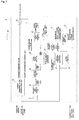
- the turning control controller 5 includes a reference gravity torque calculation unit 51, a gravity compensation torque calculation unit 52, and a correction unit 53.
- the reference gravity torque calculation unit 51 calculates a reference gravity torque TGBASE_SWING, which is a torque component generated about the turning axis by gravity in the reference attitude.
- TGBASE_SWING a torque component generated about the turning axis by gravity in the reference attitude.
- the reference attitude is an attitude in which the angle of the slope is 90 degrees, and the bucket position is 90 degrees from the front.
- the reference attitude is an attitude in which the moment of the force generated by gravity acts 100% on the rotation axis.
- the reference gravity torque calculation unit 51 calculates a reference gravity torque on the basis of the current attitude and a deviation between the actual angular acceleration and the reference angular acceleration to be generated when the electric turning motor is driven at the torque command value.
- the gravity compensation torque calculation unit 52 calculates a gravity compensation torque for compensating a torque component generated about the turning axis by gravity in the current attitude. This utilizes the fact that the gravity compensation torque can be calculated using an inner product of the reference gravity torque and the current attitude (roll angle, pitch angle). The detailed formula will be described later.
- the correction unit 53 uses the gravity compensation torque calculated by the gravity compensation torque calculation unit 52 to correct the torque command value with the gravity compensation torque so as to cancel the torque component generated about the turning axis by gravity in the current attitude. An addition is performed in the drawing because the gravity compensation torque is calculated as a negative value to perform the cancellation.
- a pre-correction torque command calculation unit 54 calculates a pre-correction torque command value on the basis of the torque command value after correction by the correction unit 53 and the gravity compensation torque used by the correction unit 53. This is because the torque command value used to estimate the reference angular acceleration is calculated by subtracting the gravity compensation torque component from the current torque command value (post-correction).
- the unit of tTCal is Newton meters.
- the "i-1" appended to the post-correction torque command value and the gravity compensation torque indicates that they are previous values.
- the value i represents the current value
- i-1 represents the previous value.
- the current value is assumed unless otherwise specified.
- a phase compensation unit 55 performs processing that delays the phase of the torque command value before being input to the reference angular acceleration calculation unit 57, which calculates the reference angular acceleration to be generated when the electric turning motor 134 is driven at the torque command value. This is because it has been found that even if a current corresponding to the torque command value is input to the electric turning motor 134, the desired angular acceleration is not immediately exhibited, and the phase (time) is slightly delayed. That is to say, as a result of delays in communication and delays due to current control by the inverter, a shift occurs in the time axis between the turning motion estimated from the torque command value of the current instruction (angular acceleration), and the turning motion currently being detected (actual angular acceleration).
- the phase compensation unit 55 compensates for this deviation in the time axis (phase). Specifically, in the present embodiment, a low-pass filter is applied to the torque command value.
- a low-pass filter is used in the present embodiment, it is not limited to this as long as the torque command value can be delayed.
- phase compensation unit 55 Although the accuracy will deteriorate, it is possible to omit the phase compensation unit 55.
- a viscous friction removal unit 56 removes a viscous friction torque from the torque command value because the viscous friction torque required to maintain the motor rotation speed ⁇ SWING [rpm] does not contribute to the increase or decrease in the angular acceleration.
- K CVIS is a viscous friction coefficient. Although the accuracy will deteriorate, it is possible to omit the viscous friction removal unit 56.
- the reciprocal of the inertia (moment of inertia) is acquired from a table which takes the reference gravity torque TGBASE_SWING as input.
- the table is correlation data 57a that associates a value representing the inertia (reciprocal of the inertia) of the upper turning body 13, which includes the work machine 12, with the reference gravity torque in advance.
- the reference gravity torque and the inertia are not in a 1:1 relationship, and the inertia cannot be calculated directly from the reference gravity torque.
- undetermined variables in the correlation data 57a are approximated as having only small variations in the backhoe 1.
- the inertia is associated in advance in the correlation data as an approximated value, a value representing the inertia (reciprocal of the inertia) can be derived and the reference angular acceleration can be calculated.
- the correlation data 57a uses predicted values or actually measured values.
- An actual angular acceleration deviation calculation unit 58 calculates a deviation DelAcc between an actual angular acceleration ActAcc, which is obtained from a value representing the rotation speed (motor rotation speed), and the reference angular acceleration ReferAcc.
- the reference gravity torque calculation unit 51 is a learning unit that newly calculates the reference gravity torque TGBASE_SWING on the basis of the reference gravity torque TGBASE_SWING i-1 calculated the previous time, the angular acceleration deviation DelAcc, and the current attitude (roll angle, pitch angle). In this way, because the reference gravity torque calculation unit 51 performs the calculation using the reference gravity torque TGBASE_SWING i-1 calculated the previous time, it is capable of learning the previous result and improving the compensation accuracy.
- the new reference gravity torque TGBASE_SWING is calculated by executing learning processing that cumulatively adds the angular acceleration deviation DelAcc multiplied by a gain to the reference gravity torque TGBASE_SWING i-1 .
- Reference gravity torque TGBASE _ SWING Reference gravity torque TGBASE _ SWING i ⁇ 1 + Gain ⁇ Angular acceleration deviation DelAcc
- the gain is such that, by taking a product containing the inner product value of a gravity vector and the turning direction [cos(pitch angle) ⁇ sin(roll angle], learning is active only when gravity caused by a slope contributes to the turning.
- Gain Gain constant ⁇ cos pitch angle ⁇ sin roll angle
- the reference gravity torque calculation unit 51 is a learning unit that executes learning processing that cumulatively adds to the reference gravity torque TGBASE_SWING i-1 calculated the previous time, the learning processing does not have to be executed.
- a configuration is possible in which the reference gravity torque TGBASE_SWING is directly calculated by multiplying the angular acceleration deviation DelAcc by a conversion coefficient, or a table or function format that takes the angular acceleration deviation DelAcc as an input value and outputs the reference gravity torque TGBASE_SWING is also possible.
- the gravity compensation torque calculation unit 52 calculates a gravity compensation torque TG_SWING for compensating a torque component generated about the turning axis by gravity in the current attitude.
- a learning cessation determining unit 59 determines whether or not a state in which learning should be stopped has occurred.
- the state in which learning should be stopped is a state where the upper turning body 13 is accelerating in a descending direction of a sloping surface, or a state where the upper turning body 13 is decelerating in an ascending direction of a sloping surface.
- the learning cessation determining unit 59 outputs the determination result as a learning active/inactive flag.
- the learning active/inactive flag is input to the reference gravity torque calculation unit 51.
- the reference gravity torque calculation unit 51 is configured such that, when the learning cessation determining unit 59 determines that a state in which learning should be stopped has occurred, the reference gravity torque calculated the previous time is used as the new reference gravity torque, and learning processing using the angular acceleration deviation is not executed.
- Reference gravity torque TGBASE _ SWING Reference gravity torque TGBASE _ SWING i ⁇ 1 + Gain ⁇ Angular acceleration deviation DelAcc
- the deviation that occurs between the actual angular acceleration and the reference angular acceleration to be generated on the basis of the torque command is caused by a change in the moment of inertia due to an expansion or contraction in the boom or the arm, or by a change in the gravity torque due to a change in the load weight. Because it is not possible to distinguish whether the moment of inertia or the gravity torque has changed, learning is possible in a state where the moment or inertia and the gravity torque have both increased, or in a state where the moment of inertia and the gravity torque have both decreased.
- the first method is a method used to determine whether or not the direction in which gravity is applied and the turning force direction of the motor coincide. Learning is possible if the directions coincide, and the learning stopped state occurs when the directions do not coincide. Specifically, it is determined whether or not the sign of a gravity compensation torque TG_SWING generated about the turning axis by gravity coincides with that of the torque (SWING_TRQ_FIN-TG_SWING) that contributes to the acceleration of the turning axis. The product of (SWING_TRQ_FIN-TG_SWING) and TG_SWING is calculated, and a positive result indicates that the signs coincide and learning is possible, and a negative result indicates that the signs do not coincide and learning is stopped.
- the second method is capable of determining, from the current attitude and the actual turning speed, whether the upper turning body 13 is moving in the descending direction of a slope, or moving in an ascending direction. Furthermore, depending on whether the absolute speed is increasing or decreasing, it is determined whether the upper turning body 13 is in a state where it is accelerating in a descending direction of a sloping surface, or the upper turning body 13 is in a state where it is decelerating in an ascending direction of a sloping surface.
- FIG. 8 is a diagram showing a turning control result of the backhoe of the first embodiment.
- FIG. 9 is a diagram showing a conventional turning control result without correction by a gravity compensation torque. Both diagrams illustrate the torque, the target rotation speed, and the actual rotation speed when the backhoe is placed on ground having a slope of 15 degrees and the upper turning body 13 is turned. As shown in FIG. 9 , during the turn at 14 to 18 seconds, and during the turn at 19 to 24 seconds, it can be seen that the actual rotation speed falls below zero even though the target rotation speed is zero. This illustrates a situation where the upper turning body 13 starts to drop due to gravity, and has been stopped by an electromagnetic brake.
- a load weight calculation unit 60 that calculates a load weight of the work machine 12.
- the load weight calculation unit 60 calculates the load weight by inputting data from a sensor 61, such as a hydraulic sensor that measures the hydraulic pressure driving the work machine 12, or a load cell that measures the weight.
- correlation data 57a is provided that associates a value representing the inertia (reciprocal of the inertia) of the upper turning body 13, which includes the work machine 12, with the load weight and the reference gravity torque in advance.
- the value representing the inertia is the reciprocal of the inertia in the present embodiment, it is not limited to this and may be the inertia itself.
- the correlation data 57a employs a two-dimensional map, various changes are possible as long as it is data in which a value representing the inertia is associated with the load weight and the reference gravity torque.
- the reference gravity torque and the inertia are not in a 1:1 relationship, and the inertia cannot be calculated directly from the reference gravity torque.
- the inertia is associated in advance in the correlation data as an approximated value, a value representing the inertia (reciprocal of the inertia) can be derived and the reference angular acceleration can be calculated.
- the association is not only with the reference gravity torque but also with the load weight, the only unknown term is the turning radius, and therefore, the accuracy of the inertia can be improved compared to the first embodiment.
- a turning radius calculation unit 62 is provided that calculates a turning radius of the work machine 12.
- the turning radius calculation unit 62 inputs data from a position detection sensor 63, which detects the stroke positions of the boom cylinder 12d and the arm cylinder 12e, specifies the angles of the boom 12a and the arm 12b from the stroke positions, and calculates the turning radius from the angles on the basis of forward kinematics.
- correlation data 57a is provided that associates a value representing the inertia (reciprocal of the inertia) of the upper turning body 13, which includes the work machine 12, with the turning radius and the reference gravity torque in advance.
- the value representing the inertia is the reciprocal of the inertia in the present embodiment, it is not limited to this and may be the inertia itself.
- the correlation data 57a employs a two-dimensional map, various changes are possible as long as it is data in which a value representing the inertia is associated with the turning radius and the reference gravity torque.
- the reference gravity torque and the inertia are not in a 1:1 relationship, and the inertia cannot be calculated directly from the reference gravity torque.
- the inertia is associated in advance in the correlation data as an approximated value, a value representing the inertia (reciprocal of the inertia) can be derived and the reference angular acceleration can be calculated.
- the association is not only with the reference gravity torque but also with the turning radius, the only unknown term is the load weight, and therefore, the accuracy of the inertia can be improved compared to the first embodiment.
- the construction machines of the first to third embodiments include:
- a feed-forward control is provided that, on the basis of the current attitude and the reference gravity torque TGBASE_SWING, which is a torque component generated about the turning axis by gravity in the reference attitude, corrects the torque command value so as to cancel the torque component generated about the turning axis by gravity in the current attitude, and therefore, a control can be performed that cancels the torque component in advance even when a delay in the rotation speed caused by the torque component generated by gravity has not actually occurred.
- the reference gravity torque TGBASE_SWING which is the torque component generated about the turning axis by gravity in the reference attitude, is calculated on the basis of the current attitude and the deviation between the actual angular acceleration ActAcc and the reference angular acceleration ReferAcc to be generated when the electric turning motor 134 is driven at the torque command value, and therefore, it is possible to appropriately cancel the torque component generated by gravity in the current attitude even when the weight changes, or when the boom or the arm is expanded or contracted.
- the reference gravity torque calculation unit 51 newly calculates the reference gravity torque TGBASE_SWING by executing learning processing, which cumulatively adds a value based on the deviation DelAcc and the current attitude to the reference gravity torque TGBASE_SWING i-1 calculated the previous time.
- the deviation that occurs between the actual angular acceleration ActAcc and the reference angular acceleration ReferAcc to be generated on the basis of the torque command is caused by a change in the moment of inertia due to an expansion or contraction in the boom or the arm, or by a change in the gravity torque due to a change in the load weight. Because it is not possible to distinguish whether the moment of inertia or the gravity torque has changed, learning is possible in a state where the moment or inertia and the gravity torque have both increased, or in a state where the moment of inertia and the gravity torque have both decreased.
- a learning cessation determining unit 59 determines whether or not a state in which learning should be stopped has occurred.
- the state in which learning should be stopped is a state where the upper turning body 13 is accelerating in a descending direction of a sloping surface, or a state where the upper turning body 13 is decelerating in an ascending direction of a sloping surface.
- the reference gravity torque calculation unit 51 is configured such that, when the learning cessation determining unit 59 determines that a state in which learning should be stopped has occurred, the reference gravity torque TGBASE_SWING i-1 calculated the previous time is used as the new reference gravity torque TGBASE_SWING, and learning processing using the angular acceleration deviation DelAcc is not executed.
- a phase compensation unit 55 that performs processing that delays the phase of the torque command value before the torque command value is input to the reference angular acceleration calculation unit 57.
- correlation data 57a is provided that associates a value representing the inertia (reciprocal of the inertia) of the upper turning body 13, which includes the work machine 12, with the reference gravity torque TGBASE_SWING in advance.
- the reference angular acceleration calculation unit 57 calculates the reference angular acceleration ReferAcc on the basis of the torque command value and a value representing the inertia in the correlation data 57a (reciprocal of the inertia) corresponding to the reference gravity torque TGBASE_SWING.
- the reference gravity torque and the inertia are not in a 1:1 relationship, and the inertia cannot be calculated directly from the reference gravity torque.
- undetermined variables in the correlation data 57a are approximated as having only small variations in the backhoe 1.
- a value representing the inertia can be derived and the reference angular acceleration ReferAcc can be calculated.
- the second embodiment includes a load weight calculation unit 60 that calculates a load weight of the work machine 12, and correlation data 57a that associates a value representing the inertia (reciprocal of the inertia) of the upper turning body 13, which includes the work machine 12, with the load weight and the reference gravity torque TGBASE_SWING in advance.
- the reference angular acceleration calculation unit 57 calculates the reference angular acceleration ReferAcc on the basis of the torque command value and a value representing the inertia (reciprocal of the inertia) corresponding to the reference gravity torque TGBASE_SWING and the load weight in the correlation data 57a.
- the reference gravity torque and the inertia are not in a 1:1 relationship, and the inertia cannot be calculated directly from the reference gravity torque.
- undetermined variables in the correlation data 57a are approximated as having only small variations in the backhoe 1.
- a value representing the inertia can be derived and the reference angular acceleration ReferAcc can be calculated.
- the association is not only with the reference gravity torque but also with the load weight, the only unknown term is the turning radius, and therefore, the accuracy of the inertia can be improved compared to the first embodiment.
- the third embodiment includes a turning radius calculation unit 62 that calculates a turning radius of the work machine 12, and correlation data 57a that associates a value representing the inertia (reciprocal of the inertia) of the upper turning body 13, which includes the work machine 12, with the turning radius and the reference gravity torque TGBASE_SWING in advance.
- the reference angular acceleration calculation unit 57 calculates the reference angular acceleration ReferAcc on the basis of the torque command value and a value representing the inertia (reciprocal of the inertia) corresponding to the reference gravity torque TGBASE_SWING and the turning radius in the correlation data 57a.
- the reference gravity torque and the inertia are not in a 1:1 relationship, and the inertia cannot be calculated directly from the reference gravity torque.
- undetermined variables in the correlation data 57a are approximated as having only small variations in the backhoe 1.
- a value representing the inertia can be derived and the reference angular acceleration ReferAcc can be calculated.
- the association is not only with the reference gravity torque but also with the turning radius, the only unknown term is the load weight, and therefore, the accuracy of the inertia can be improved compared to the first embodiment.
Landscapes
- Engineering & Computer Science (AREA)
- General Engineering & Computer Science (AREA)
- Structural Engineering (AREA)
- Civil Engineering (AREA)
- Mining & Mineral Resources (AREA)
- Theoretical Computer Science (AREA)
- Software Systems (AREA)
- Mechanical Engineering (AREA)
- Evolutionary Computation (AREA)
- Computing Systems (AREA)
- General Physics & Mathematics (AREA)
- Mathematical Physics (AREA)
- Physics & Mathematics (AREA)
- Data Mining & Analysis (AREA)
- Artificial Intelligence (AREA)
- Medical Informatics (AREA)
- Computer Vision & Pattern Recognition (AREA)
- Computational Linguistics (AREA)
- Operation Control Of Excavators (AREA)
Abstract
Description
- The present disclosure relates to a construction machine that turns by means of an electric turning motor.
- For example, as described in
Patent Literature - In
Patent Literature 1, a technique is disclosed that, in order to ensure that a stationary state of the upper turning body is maintained on sloping ground, switches a control command of the electric turning motor from a speed control to a position control when an operation lever is in a neutral position and the target speed of the upper turning body falls below a predetermined threshold. - In
Patent Literature 2, disclosed as a turning drive control device of a construction machine which is driven to turn by an electric motor is a control device that, when turning motion in the opposite direction to a turning operation direction is detected, reduces the turning motion in the opposite direction on the condition that the construction machine is not positioned on flat ground. -
- Patent Literature 1:
Japanese Unexamined Patent Application Publication No. 2012-122327 - Patent Literature 2:
Japanese Unexamined Patent Application Publication No. 2010-138586 - However, in
Patent Literature - In
Patent Literature 2, because a control that reduces the turning motion in the opposite direction does not come into effect until the turning motion in the opposite direction to the turning operation direction is detected, an unintended drop of the upper turning body always occurs. - In both
Patent Literature - In view of the above problems, the present disclosure provides a construction machine capable of comfortably performing turning motion on sloping ground without exhibiting the adverse effects of a torque component generated by gravity.
- A construction machine of the present disclosure includes:
- an upper turning body comprising a work machine;
- a lower traveling body that supports the upper turning body so as to be capable of turning via a turning axis;
- an electric turning motor that causes the upper turning body to turn;
- a rotation speed acquisition unit that acquires a value representing a rotation speed of the upper turning body;
- an attitude sensor that detects a current attitude of the upper turning body;
- a torque command value generation unit that outputs a torque command value to the electric turning motor according to an operation amount of an operation part;
- a reference angular acceleration calculation unit that calculates a reference angular acceleration to be generated when the electric turning motor is driven at the torque command value;
- a reference gravity torque calculation unit that calculates a reference gravity torque which is a torque component generated about the turning axis by gravity in a reference attitude on the basis of the current attitude and a deviation between an actual angular acceleration obtained from the rotation speed and the reference angular acceleration;
- a gravity compensation torque calculation unit that calculates a gravity compensation torque for compensating a torque component generated about the turning axis by gravity in the current attitude on the basis of the reference gravity torque and the current attitude; and
- a correction unit that corrects the torque command value with the gravity compensation torque so as to cancel a torque component generated about the turning axis by gravity in the current attitude.
- As described above, a feed-forward control is provided that, on the basis of the current attitude and the reference gravity torque, which is a torque component generated about the turning axis by gravity in the reference attitude, corrects the torque command value so as to cancel the torque component generated about the turning axis by gravity in the current attitude, and therefore, a control can be performed that cancels the torque component in advance even when a delay in the rotation speed caused by the torque component generated by gravity has not actually occurred.
- Meanwhile, the reference gravity torque, which is the torque component generated about the turning axis by gravity in the reference attitude, is calculated on the basis of the current attitude and the deviation between the actual angular acceleration and the reference angular acceleration to be generated when the electric turning motor is driven at the torque command value, and therefore, it is possible to appropriately cancel the torque component generated by gravity in the current attitude even when the weight changes, or when the boom or the arm is expanded or contracted.
- Therefore, it is possible to comfortably perform turning motion on sloping ground without exhibiting the adverse effects of a torque component generated by gravity.
-
-
FIG. 1 is a side view showing a backhoe of a first embodiment. -
FIG. 2 is a plan view showing the backhoe of the first embodiment. -
FIG. 3 is a diagram showing an electric circuit mounted on the backhoe of the first embodiment. -
FIG. 4 is a diagram showing a turning control controller of the first embodiment. -
FIG. 5 is a diagram showing an example of a reference attitude. -
FIG. 6 is a diagram showing a turning control controller of a second embodiment. -
FIG. 7 is a diagram showing a turning control controller of a third embodiment. -
FIG. 8 is a diagram showing a turning control result of the backhoe of the first embodiment. -
FIG. 9 is a diagram showing a conventional turning control result without correction by a gravity compensation torque. - Hereinafter, a first embodiment of the present disclosure will be described with reference to the drawings.
- As shown in
FIG. 1 andFIG. 2 , a schematic structure of abackhoe 1 will be described as an example of a hybrid construction machine. Thebackhoe 1 includes alower traveling body 11, awork machine 12, and an upper turningbody 13. - The lower traveling
body 11 is driven by receiving power from anengine 2 housed inside the upper turningbody 13, and causes thebackhoe 1 to travel. The lower travelingbody 11 includes a pair of left andright crawlers right traveling motors backhoe 1 is made possible as a result of the pair of left and right travelingmotors right crawlers body 11 is provided with ablade 11c, and ablade cylinder 11d for causing theblade 11c to rotate in the up-down direction. - The
work machine 12 is driven by receiving power from theengine 2, and performs excavation work with respect to earth and sand and the like. Thework machine 12 includes aboom 12a, anarm 12b, and abucket 12c, and excavation work is made possible by independently driving these components. Theboom 12a, thearm 12b, and thebucket 12c each correspond to a working unit, and thebackhoe 1 has a plurality of working units. - One end of the
boom 12a is supported by the front portion of the upper turningbody 13, and is rotated by aboom cylinder 12d that can be freely expanded and contracted. Furthermore, one end of thearm 12b is supported by the other end of theboom 12a, and is rotated by anarm cylinder 12e that can be freely expanded and contracted. In addition, one end of thebucket 12c is supported by the other end of thearm 12b, and is rotated by abucket cylinder 12f that can be freely expanded and contracted. - The upper turning
body 13 is configured so as to be capable of turning with respect to the lower travelingbody 11 via a turning bearing (not shown), which is a turning axis. Acabin 131, abonnet 132, acounterweight 133, anelectric turning motor 134, theengine 2, anattitude sensor 130, and the like are arranged in the upper turningbody 13. The upper turningbody 13 turns via the turning bearing (not shown) by the driving force of theelectric turning motor 134. Furthermore, anelectric generator 3 and ahydraulic pump 4, which are driven by theengine 2, are arranged in the upper turningbody 13. Thehydraulic pump 4 supplies hydraulic oil to each hydraulic motor and each cylinder. - The
attitude sensor 130 detects the current attitude of the upper turningbody 13. The current attitude is represented by a roll angle, which has the front-rear direction of the upper turningbody 13 as the rotation axis, and a pitch angle, which has the left-right direction of the upper turningbody 13 as the rotation axis. A yaw angle, which has the up-down direction of the upper turningbody 13 as the rotation axis, is not used because it can be found by the rotation of theelectric turning motor 134. Although theattitude sensor 130 is a gyroscope in the present embodiment, it is not limited thereto, and various modifications are possible. - The
cabin 131 is erected on the left side portion of theupper turning body 13. A driver'sseat 131a is arranged in thecabin 131. A pair ofwork operation levers 131c is arranged on the left and right sides of the driver'sseat 131a (seeFIG. 3 ), and a pair of travel levers 131b and 131b is arranged at the front. An operator sits in the driver'sseat 131a and operates the work operation levers 131c, the travel levers 131b and 131b, and the like to control theengine 2, the hydraulic motors, and the hydraulic cylinders, which enables traveling, turning, and work and the like to be performed. - The
bonnet 132 and thecounterweight 133 are vertically arranged on the rear end portion of theupper turning body 13. Thecounterweight 133 is erected on the rear end portion of theupper turning body 13, and covers theengine 2. Thebonnet 132 extends upward from the upper end portion of thecounterweight 133 so as to reach the lower end portion of the rear wall of thecabin 131, and covers theengine 2 together with thecounterweight 133. The rear end portion of theupper turning body 13 is formed with an arc shape in plan view, and thebonnet 132 and thecounterweight 133 are formed so as to be curved along the rear end portion of theupper turning body 13. Thebackhoe 1 of the present embodiment is called a rear small turning type. - Next, the configuration of the electric circuit mounted on the
backhoe 1 will be described. As shown inFIG. 3 , thebackhoe 1 includes aturning control controller 5, aninverter 31, abattery 32, and anelectric turning motor 134. The turningcontrol controller 5 controls the drive of theelectric turning motor 134 on the basis of a turning operation amount of the work operation levers 131c (operation parts), the current attitude detected by theattitude sensor 130, and the motor rotation speed per unit time [rpm]. Theelectric turning motor 134 is controlled by the turningcontrol controller 5 via theinverter 31. Theelectric turning motor 134 is connected to thebattery 32 via theinverter 31. Thebattery 32 supplies drive energy to theelectric turning motor 134. As shown inFIG. 2 , thebattery 32 is arranged on the right side of thecabin 131. Theinverter 31 controls theelectric turning motor 134. Theinverter 31 discharges power from thebattery 32 and drives theelectric turning motor 134 on the basis of a torque command value from the turningcontrol controller 5. Theinverter 31 acts as a rotation speed acquisition unit and inputs the rotation speed per unit time of theelectric turning motor 134 to theturning control controller 5. Of course, a separate sensor may be provided to detect the rotation speed of theupper turning body 13. - Next, the configuration of the turning
control controller 5 will be described. As shown inFIG. 4 , the turningcontrol controller 5 has a torque commandvalue generation unit 50. - The torque command
value generation unit 50 outputs a torque command value to theelectric turning motor 134 according to an operation amount of the work operation levers 131c, which are operation parts. Although the torque commandvalue generation unit 50 is not described in detail because it represents a conventional turning control performed on flat ground, it outputs the torque command value so that the deviation is eliminated between a target rotation speed determined according to the operation amount, and an actual rotation speed represented by the motor rotation speed per unit time. - As shown in
FIG. 4 , in order to cancel the torque component generated by gravity, the turningcontrol controller 5 includes a reference gravitytorque calculation unit 51, a gravity compensationtorque calculation unit 52, and acorrection unit 53. - The reference gravity
torque calculation unit 51 calculates a reference gravity torque TGBASE_SWING, which is a torque component generated about the turning axis by gravity in the reference attitude. Although various reference attitudes can be set, as shown inFIG. 5 , in the present embodiment the reference attitude is an attitude in which the angle of the slope is 90 degrees, and the bucket position is 90 degrees from the front. The reference attitude is an attitude in which the moment of the force generated bygravity acts 100% on the rotation axis. The reference gravitytorque calculation unit 51 calculates a reference gravity torque on the basis of the current attitude and a deviation between the actual angular acceleration and the reference angular acceleration to be generated when the electric turning motor is driven at the torque command value. When the reference angular acceleration to be generated on the basis of the torque command value output to theelectric turning motor 134 is calculated by a prediction, it is currently thought that when the actual angular acceleration is slower than the predicted reference angular acceleration, this is due to the effect of gravity, and conversely, when the actual angular acceleration is faster, this is also due to the effect of gravity. Therefore, the true reference gravity torque has been calculated when the deviation between the angular accelerations is eliminated. - The gravity compensation
torque calculation unit 52, on the basis of the reference gravity torque calculated by the reference gravitytorque calculation unit 51 and the current attitude, calculates a gravity compensation torque for compensating a torque component generated about the turning axis by gravity in the current attitude. This utilizes the fact that the gravity compensation torque can be calculated using an inner product of the reference gravity torque and the current attitude (roll angle, pitch angle). The detailed formula will be described later. - The
correction unit 53 uses the gravity compensation torque calculated by the gravity compensationtorque calculation unit 52 to correct the torque command value with the gravity compensation torque so as to cancel the torque component generated about the turning axis by gravity in the current attitude. An addition is performed in the drawing because the gravity compensation torque is calculated as a negative value to perform the cancellation. - The above is an outline, and the details will now be described.
- A pre-correction torque
command calculation unit 54 calculates a pre-correction torque command value on the basis of the torque command value after correction by thecorrection unit 53 and the gravity compensation torque used by thecorrection unit 53. This is because the torque command value used to estimate the reference angular acceleration is calculated by subtracting the gravity compensation torque component from the current torque command value (post-correction). The formula is expressed as follows.
- The unit of tTCal is Newton meters. Here, the "i-1" appended to the post-correction torque command value and the gravity compensation torque indicates that they are previous values. The value i represents the current value, and i-1 represents the previous value. The current value is assumed unless otherwise specified.
- A
phase compensation unit 55 performs processing that delays the phase of the torque command value before being input to the reference angularacceleration calculation unit 57, which calculates the reference angular acceleration to be generated when theelectric turning motor 134 is driven at the torque command value. This is because it has been found that even if a current corresponding to the torque command value is input to theelectric turning motor 134, the desired angular acceleration is not immediately exhibited, and the phase (time) is slightly delayed. That is to say, as a result of delays in communication and delays due to current control by the inverter, a shift occurs in the time axis between the turning motion estimated from the torque command value of the current instruction (angular acceleration), and the turning motion currently being detected (actual angular acceleration). Thephase compensation unit 55 compensates for this deviation in the time axis (phase). Specifically, in the present embodiment, a low-pass filter is applied to the torque command value. The formula is as follows:
- Although a low-pass filter is used in the present embodiment, it is not limited to this as long as the torque command value can be delayed.
- Although the accuracy will deteriorate, it is possible to omit the
phase compensation unit 55. - A viscous
friction removal unit 56 removes a viscous friction torque from the torque command value because the viscous friction torque required to maintain the motor rotation speed ωSWING [rpm] does not contribute to the increase or decrease in the angular acceleration. The formula is as follows:
- Post-removal torque command value tTCal_Fin = tTCal_Filt - tTVis
- Here, KCVIS is a viscous friction coefficient. Although the accuracy will deteriorate, it is possible to omit the viscous
friction removal unit 56. - A reference angular
acceleration calculation unit 57 calculates a reference angular acceleration ReferAcc to be generated when theelectric turning motor 134 is driven at the torque command value. Specifically, the angular acceleration ReferAcc is calculated by multiplying the torque command value tTCal_Fin by the reciprocal of the inertia. The formula is as follows:
- The reciprocal of the inertia (moment of inertia) is acquired from a table which takes the reference gravity torque TGBASE_SWING as input. The table is
correlation data 57a that associates a value representing the inertia (reciprocal of the inertia) of theupper turning body 13, which includes thework machine 12, with the reference gravity torque in advance. The reference gravity torque and the inertia (moment of inertia) are not in a 1:1 relationship, and the inertia cannot be calculated directly from the reference gravity torque. However, undetermined variables in thecorrelation data 57a are approximated as having only small variations in thebackhoe 1. In this way, because the inertia is associated in advance in the correlation data as an approximated value, a value representing the inertia (reciprocal of the inertia) can be derived and the reference angular acceleration can be calculated. Thecorrelation data 57a uses predicted values or actually measured values. - An actual angular acceleration
deviation calculation unit 58 calculates a deviation DelAcc between an actual angular acceleration ActAcc, which is obtained from a value representing the rotation speed (motor rotation speed), and the reference angular acceleration ReferAcc. The actual angular acceleration ActAcc is, as shown in the following formula, calculated from the forward difference of the motor rotation speed [rpm]:

- In the present embodiment, the reference gravity
torque calculation unit 51 is a learning unit that newly calculates the reference gravity torque TGBASE_SWING on the basis of the reference gravity torque TGBASE_SWINGi-1 calculated the previous time, the angular acceleration deviation DelAcc, and the current attitude (roll angle, pitch angle). In this way, because the reference gravitytorque calculation unit 51 performs the calculation using the reference gravity torque TGBASE_SWINGi-1 calculated the previous time, it is capable of learning the previous result and improving the compensation accuracy. - Specifically, as shown in the following formula, the new reference gravity torque TGBASE_SWING is calculated by executing learning processing that cumulatively adds the angular acceleration deviation DelAcc multiplied by a gain to the reference gravity torque TGBASE_SWINGi-1.

- The gain is such that, by taking a product containing the inner product value of a gravity vector and the turning direction [cos(pitch angle) × sin(roll angle], learning is active only when gravity caused by a slope contributes to the turning.

- In the present embodiment, although the reference gravity
torque calculation unit 51 is a learning unit that executes learning processing that cumulatively adds to the reference gravity torque TGBASE_SWINGi-1 calculated the previous time, the learning processing does not have to be executed. - For example, a configuration is possible in which the reference gravity torque TGBASE_SWING is directly calculated by multiplying the angular acceleration deviation DelAcc by a conversion coefficient, or a table or function format that takes the angular acceleration deviation DelAcc as an input value and outputs the reference gravity torque TGBASE_SWING is also possible.
- The gravity compensation
torque calculation unit 52, on the basis of the reference gravity torque TGBASE_SWING calculated by the reference gravitytorque calculation unit 51 and the current attitude (roll angle, pitch angle), calculates a gravity compensation torque TG_SWING for compensating a torque component generated about the turning axis by gravity in the current attitude. The formula is as follows:
- A learning
cessation determining unit 59 determines whether or not a state in which learning should be stopped has occurred. The state in which learning should be stopped is a state where theupper turning body 13 is accelerating in a descending direction of a sloping surface, or a state where theupper turning body 13 is decelerating in an ascending direction of a sloping surface. The learningcessation determining unit 59 outputs the determination result as a learning active/inactive flag. The learning active/inactive flag is input to the reference gravitytorque calculation unit 51. The reference gravitytorque calculation unit 51 is configured such that, when the learningcessation determining unit 59 determines that a state in which learning should be stopped has occurred, the reference gravity torque calculated the previous time is used as the new reference gravity torque, and learning processing using the angular acceleration deviation is not executed. In the learning stopped state, the reference gravity torque is calculated by the following formula.
Formula in learning stopped state:
- On the other hand, if the learning
cessation determining unit 59 determines a state in which learning should be stopped has not occurred, the reference gravitytorque calculation unit 51 executes learning processing using the deviation described above. The formula is reproduced below.
Formula in learning state:
- The deviation that occurs between the actual angular acceleration and the reference angular acceleration to be generated on the basis of the torque command is caused by a change in the moment of inertia due to an expansion or contraction in the boom or the arm, or by a change in the gravity torque due to a change in the load weight. Because it is not possible to distinguish whether the moment of inertia or the gravity torque has changed, learning is possible in a state where the moment or inertia and the gravity torque have both increased, or in a state where the moment of inertia and the gravity torque have both decreased. On the other hand, in a state where the moment of inertia has increased and the gravity torque has decreased, or in a state where the moment of inertia has decreased and the gravity torque has increased, the two components have changed in opposite directions, and therefore, a state in which learning should be stopped has occurred because erroneous learning will occur.
- Therefore, when it is determined whether or a state in which learning should be stopped has occurred, and it is determined that a state in which learning should be stopped has occurred, because a configuration is used in which the reference gravity torque calculated the previous time is used as the new reference gravity torque as is, and learning processing using a deviation is not executed, it is possible to prevent erroneous learning and to improve the compensation accuracy.
- There are two possible implementation methods of the learning
cessation determining unit 59. - The first method is a method used to determine whether or not the direction in which gravity is applied and the turning force direction of the motor coincide. Learning is possible if the directions coincide, and the learning stopped state occurs when the directions do not coincide. Specifically, it is determined whether or not the sign of a gravity compensation torque TG_SWING generated about the turning axis by gravity coincides with that of the torque (SWING_TRQ_FIN-TG_SWING) that contributes to the acceleration of the turning axis. The product of (SWING_TRQ_FIN-TG_SWING) and TG_SWING is calculated, and a positive result indicates that the signs coincide and learning is possible, and a negative result indicates that the signs do not coincide and learning is stopped.
- The second method is capable of determining, from the current attitude and the actual turning speed, whether the
upper turning body 13 is moving in the descending direction of a slope, or moving in an ascending direction. Furthermore, depending on whether the absolute speed is increasing or decreasing, it is determined whether theupper turning body 13 is in a state where it is accelerating in a descending direction of a sloping surface, or theupper turning body 13 is in a state where it is decelerating in an ascending direction of a sloping surface. - A turning control result of the first embodiment and a conventional turning control result without correction by a gravity compensation torque will be comparatively described.
FIG. 8 is a diagram showing a turning control result of the backhoe of the first embodiment.FIG. 9 is a diagram showing a conventional turning control result without correction by a gravity compensation torque. Both diagrams illustrate the torque, the target rotation speed, and the actual rotation speed when the backhoe is placed on ground having a slope of 15 degrees and theupper turning body 13 is turned. As shown inFIG. 9 , during the turn at 14 to 18 seconds, and during the turn at 19 to 24 seconds, it can be seen that the actual rotation speed falls below zero even though the target rotation speed is zero. This illustrates a situation where theupper turning body 13 starts to drop due to gravity, and has been stopped by an electromagnetic brake. - In contrast to
FIG. 9 , inFIG. 8 it can be understood that the actual rotation speed does not fall too far when the target rotation speed is zero, and the torque component generated by gravity is being appropriately corrected. It can be understood that, although variation occurs in the reference gravity torque TG_BASE, which is the torque component generated by gravity in the reference attitude, it has also converged. - A second embodiment will be described. The same components as those of the first embodiment are denoted by the same reference numbers, and the description will be omitted. As shown in
FIG. 6 , a loadweight calculation unit 60 is provided that calculates a load weight of thework machine 12. The loadweight calculation unit 60 calculates the load weight by inputting data from asensor 61, such as a hydraulic sensor that measures the hydraulic pressure driving thework machine 12, or a load cell that measures the weight. - Furthermore,
correlation data 57a is provided that associates a value representing the inertia (reciprocal of the inertia) of theupper turning body 13, which includes thework machine 12, with the load weight and the reference gravity torque in advance. Although the value representing the inertia is the reciprocal of the inertia in the present embodiment, it is not limited to this and may be the inertia itself. In the present embodiment, although thecorrelation data 57a employs a two-dimensional map, various changes are possible as long as it is data in which a value representing the inertia is associated with the load weight and the reference gravity torque. - The reference gravity torque and the inertia (moment of inertia) are not in a 1:1 relationship, and the inertia cannot be calculated directly from the reference gravity torque. However, in this way, because the inertia is associated in advance in the correlation data as an approximated value, a value representing the inertia (reciprocal of the inertia) can be derived and the reference angular acceleration can be calculated.
- Further, because the association is not only with the reference gravity torque but also with the load weight, the only unknown term is the turning radius, and therefore, the accuracy of the inertia can be improved compared to the first embodiment.
- A third embodiment will be described. The same components as those of the first embodiment are denoted by the same reference numbers, and the description will be omitted. As shown in
FIG. 7 , a turningradius calculation unit 62 is provided that calculates a turning radius of thework machine 12. The turningradius calculation unit 62 inputs data from aposition detection sensor 63, which detects the stroke positions of theboom cylinder 12d and thearm cylinder 12e, specifies the angles of theboom 12a and thearm 12b from the stroke positions, and calculates the turning radius from the angles on the basis of forward kinematics. - Furthermore,
correlation data 57a is provided that associates a value representing the inertia (reciprocal of the inertia) of theupper turning body 13, which includes thework machine 12, with the turning radius and the reference gravity torque in advance. Although the value representing the inertia is the reciprocal of the inertia in the present embodiment, it is not limited to this and may be the inertia itself. In the present embodiment, although thecorrelation data 57a employs a two-dimensional map, various changes are possible as long as it is data in which a value representing the inertia is associated with the turning radius and the reference gravity torque. - The reference gravity torque and the inertia (moment of inertia) are not in a 1:1 relationship, and the inertia cannot be calculated directly from the reference gravity torque. However, in this way, because the inertia is associated in advance in the correlation data as an approximated value, a value representing the inertia (reciprocal of the inertia) can be derived and the reference angular acceleration can be calculated.
- Further, because the association is not only with the reference gravity torque but also with the turning radius, the only unknown term is the load weight, and therefore, the accuracy of the inertia can be improved compared to the first embodiment.
- As described above, the construction machines of the first to third embodiments include:
- an
upper turning body 13 comprising awork machine 12; - a
lower traveling body 11 that supports theupper turning body 13 so as to be capable of turning via a turning axis; - an
electric turning motor 134 that causes theupper turning body 13 to turn; - a rotation speed acquisition unit (inverter 31) that acquires a value representing a rotation speed of the upper turning body 13 (motor rotation speed per unit time);
- an
attitude sensor 130 that detects a current attitude of theupper turning body 13; - a torque command
value generation unit 50 that outputs a torque command value to theelectric turning motor 134 according to an operation amount of an operation part; - a reference angular
acceleration calculation unit 57 that calculates a reference angular acceleration ReferAcc to be generated when theelectric turning motor 134 is driven at the torque command value; - a reference gravity
torque calculation unit 51 that, on the basis of the current attitude and a deviation between an actual angular acceleration ActAcc obtained from the rotation speed and the reference angular acceleration ReferAcc, calculates a reference gravity torque TGBASE_SWING which is a torque component to be generated about the turning axis by gravity in a reference attitude; - a gravity compensation
torque calculation unit 52 that, on the basis of the reference gravity torque TGBASE_SWING and the current attitude, calculates a gravity compensation torque TG_SWING for compensating a torque component generated about the turning axis by gravity in the current attitude; and - a
correction unit 53 that corrects the torque command value with the gravity compensation torque TG_SWING so as to cancel a torque component generated about the turning axis by gravity in the current attitude. - As described above, a feed-forward control is provided that, on the basis of the current attitude and the reference gravity torque
TGBASE_SWING, which is a torque component generated about the turning axis by gravity in the reference attitude, corrects the torque command value so as to cancel the torque component generated about the turning axis by gravity in the current attitude, and therefore, a control can be performed that cancels the torque component in advance even when a delay in the rotation speed caused by the torque component generated by gravity has not actually occurred. - Meanwhile, the reference gravity torque TGBASE_SWING, which is the torque component generated about the turning axis by gravity in the reference attitude, is calculated on the basis of the current attitude and the deviation between the actual angular acceleration ActAcc and the reference angular acceleration ReferAcc to be generated when the
electric turning motor 134 is driven at the torque command value, and therefore, it is possible to appropriately cancel the torque component generated by gravity in the current attitude even when the weight changes, or when the boom or the arm is expanded or contracted. - Therefore, it is possible to comfortably perform turning motion on sloping ground without exhibiting the adverse effects of a torque component generated by gravity.
- In the first to third embodiments, the reference gravity
torque calculation unit 51 newly calculates the reference gravity torque TGBASE_SWING by executing learning processing, which cumulatively adds a value based on the deviation DelAcc and the current attitude to the reference gravity torque TGBASE_SWINGi-1 calculated the previous time. - As described above, because a value based on the deviation DelAcc and the current attitude is cumulatively added to the reference gravity torque TGBASE_SWINGi-1 calculated the previous time, the previous result can be learned and the compensation accuracy can be improved.
- The deviation that occurs between the actual angular acceleration ActAcc and the reference angular acceleration ReferAcc to be generated on the basis of the torque command is caused by a change in the moment of inertia due to an expansion or contraction in the boom or the arm, or by a change in the gravity torque due to a change in the load weight. Because it is not possible to distinguish whether the moment of inertia or the gravity torque has changed, learning is possible in a state where the moment or inertia and the gravity torque have both increased, or in a state where the moment of inertia and the gravity torque have both decreased. On the other hand, in a state where the moment of inertia has increased and the gravity torque has decreased, or in a state where the moment of inertia has decreased and the gravity torque has increased, the two components are opposing each other, and therefore, a state in which learning should be stopped has occurred because erroneous learning will occur.
- In the first to third embodiments, a learning
cessation determining unit 59 is provided that determines whether or not a state in which learning should be stopped has occurred. The state in which learning should be stopped is a state where theupper turning body 13 is accelerating in a descending direction of a sloping surface, or a state where theupper turning body 13 is decelerating in an ascending direction of a sloping surface. The reference gravitytorque calculation unit 51 is configured such that, when the learningcessation determining unit 59 determines that a state in which learning should be stopped has occurred, the reference gravity torque TGBASE_SWINGi-1 calculated the previous time is used as the new reference gravity torque TGBASE_SWING, and learning processing using the angular acceleration deviation DelAcc is not executed. - In this way, when it is determined whether or a state in which learning should be stopped has occurred, and it is determined that a state in which learning should be stopped has occurred, because a configuration is used in which the reference gravity torque TGBASE_SWINGi-1 calculated the previous time is used as the new reference gravity torque TGBASE_SWING as is, and learning processing using the deviation DelAcc is not executed, it is possible to prevent erroneous learning and to improve the compensation accuracy.
- In the first to third embodiments, a
phase compensation unit 55 is provided that performs processing that delays the phase of the torque command value before the torque command value is input to the reference angularacceleration calculation unit 57. - As a result of delays in communication and delays due to current control by the inverter, a shift occurs in the time axis between the turning motion (reference angular acceleration ReferAcc) estimated from the torque command value of the current instruction, and the turning motion (actual angular acceleration ActAcc) currently being detected. However, as described above, the shift in the time axis can be compensated by performing processing that delays the phase of the torque command value, and therefore, it is possible to match both of the time axes so that the accuracy of the control is improved.
- In the first embodiment,
correlation data 57a is provided that associates a value representing the inertia (reciprocal of the inertia) of theupper turning body 13, which includes thework machine 12, with the reference gravity torque TGBASE_SWING in advance. The reference angularacceleration calculation unit 57 calculates the reference angular acceleration ReferAcc on the basis of the torque command value and a value representing the inertia in thecorrelation data 57a (reciprocal of the inertia) corresponding to the reference gravity torque TGBASE_SWING. - The reference gravity torque and the inertia (moment of inertia) are not in a 1:1 relationship, and the inertia cannot be calculated directly from the reference gravity torque. However, undetermined variables in the
correlation data 57a are approximated as having only small variations in thebackhoe 1. In this way, because the inertia is associated in advance in the correlation data as an approximated value, a value representing the inertia (reciprocal of the inertia) can be derived and the reference angular acceleration ReferAcc can be calculated. - The second embodiment includes a load
weight calculation unit 60 that calculates a load weight of thework machine 12, andcorrelation data 57a that associates a value representing the inertia (reciprocal of the inertia) of theupper turning body 13, which includes thework machine 12, with the load weight and the reference gravity torque TGBASE_SWING in advance. - The reference angular
acceleration calculation unit 57 calculates the reference angular acceleration ReferAcc on the basis of the torque command value and a value representing the inertia (reciprocal of the inertia) corresponding to the reference gravity torque TGBASE_SWING and the load weight in thecorrelation data 57a. - The reference gravity torque and the inertia (moment of inertia) are not in a 1:1 relationship, and the inertia cannot be calculated directly from the reference gravity torque. However, undetermined variables in the
correlation data 57a are approximated as having only small variations in thebackhoe 1. In this way, because the inertia is associated in advance in the correlation data as an approximated value, a value representing the inertia (reciprocal of the inertia) can be derived and the reference angular acceleration ReferAcc can be calculated. - Further, because the association is not only with the reference gravity torque but also with the load weight, the only unknown term is the turning radius, and therefore, the accuracy of the inertia can be improved compared to the first embodiment.
- The third embodiment includes a turning
radius calculation unit 62 that calculates a turning radius of thework machine 12, andcorrelation data 57a that associates a value representing the inertia (reciprocal of the inertia) of theupper turning body 13, which includes thework machine 12, with the turning radius and the reference gravity torque TGBASE_SWING in advance. - The reference angular
acceleration calculation unit 57 calculates the reference angular acceleration ReferAcc on the basis of the torque command value and a value representing the inertia (reciprocal of the inertia) corresponding to the reference gravity torque TGBASE_SWING and the turning radius in thecorrelation data 57a. - The reference gravity torque and the inertia (moment of inertia) are not in a 1:1 relationship, and the inertia cannot be calculated directly from the reference gravity torque. However, undetermined variables in the
correlation data 57a are approximated as having only small variations in thebackhoe 1. In this way, because the inertia is associated in advance in the correlation data as an approximated value, a value representing the inertia (reciprocal of the inertia) can be derived and the reference angular acceleration ReferAcc can be calculated. - Further, because the association is not only with the reference gravity torque but also with the turning radius, the only unknown term is the load weight, and therefore, the accuracy of the inertia can be improved compared to the first embodiment.
- Although embodiments of the present disclosure have been described above with reference to the drawings, the specific configurations should not be considered to be limited to these embodiments. The scope of the present disclosure is defined not only by the description of the above embodiments but by the scope of the claims, and further, all modifications that fall within a meaning and scope equivalent to the scope of the claims are included.
- It is possible to adopt the structures used in each of the above embodiments in other arbitrary embodiments.
-
- 1 Backhoe (construction machine)
- 11 Lower traveling body
- 12 Work machine
- 13 Upper turning body
- 130 Attitude sensor
- 131c Work operation lever (operation part)
- 134 Electric turning motor
- 31 Inverter (rotation speed acquisition unit)
- 50 Torque command value generation unit
- 51 Reference gravity torque calculation unit
- 52 Gravity compensation torque calculation unit
- 53 Correction unit
- 55 Phase compensation unit
- 57 Reference angular acceleration calculation unit
- 57a Correlation data
- 59 Learning cessation determining unit
- 60 Load weight calculation unit
- 62 Turning radius calculation unit
Claims (7)
- A construction machine including:an upper turning body comprising a work machine;a lower traveling body that supports the upper turning body so as to be capable of turning via a turning axis;an electric turning motor that causes the upper turning body to turn;a rotation speed acquisition unit that acquires a value representing a rotation speed of the upper turning body;an attitude sensor that detects a current attitude of the upper turning body;a torque command value generation unit that outputs a torque command value to the electric turning motor according to an operation amount of an operation part;a reference angular acceleration calculation unit that calculates a reference angular acceleration to be generated when the electric turning motor is driven at the torque command value;a reference gravity torque calculation unit that calculates a reference gravity torque which is a torque component generated about the turning axis by gravity in a reference attitude on the basis of the current attitude and a deviation between an actual angular acceleration obtained from the rotation speed and the reference angular acceleration;a gravity compensation torque calculation unit that calculates a gravity compensation torque for compensating a torque component generated about the turning axis by gravity in the current attitude on the basis of the reference gravity torque and the current attitude; anda correction unit that corrects the torque command value with the gravity compensation torque so as to cancel a torque component generated about the turning axis by gravity in the current attitude.
- The construction machine according to claim 1, wherein
the reference gravity torque calculation unit newly calculates the reference gravity torque by executing learning processing, which cumulatively adds a value based on the deviation and the current attitude to the reference gravity torque calculated the previous time. - The construction machine according to claim 2, including
a learning cessation determining unit that determines whether or not a state in which learning should be stopped has occurred, wherein
the state in which learning should be stopped is a state where the upper turning body is accelerating in a descending direction of a sloping surface, or a state where the upper turning body is decelerating in an ascending direction of a sloping surface, and
the reference gravity torque calculation unit is configured such that, if it is determined by the learning cessation determining unit that a state in which learning should be stopped has occurred, the reference gravity torque calculated the previous time is used as a new reference gravity torque, and learning processing using the deviation is not executed. - A construction machine according to any one of claims 1 to 3, including
a phase compensation unit that performs processing that delays a phase of the torque command value before the torque command value is input to the reference angular acceleration calculation unit. - A construction machine according to any one of claims 1 to 4, including
correlation data that associates a value representing an inertia of the upper turning body, which includes the work machine, with the reference gravity torque in advance, wherein
the reference angular acceleration calculation unit calculates the reference angular acceleration on the basis of the torque command value and a value representing the inertia corresponding to the reference gravity torque in the correlation data. - A construction machine according to any one of claims 1 to 4, including
a load weight calculation unit that calculates a load weight of the work machine, and
correlation data that associates a value indicating an inertia of the upper turning body, which includes the work machine, with the load weight and the reference gravity torque in advance, wherein
the reference angular acceleration calculation unit calculates the reference angular acceleration on the basis of the torque command value and a value representing the inertia corresponding to the reference gravity torque and the load weight in the correlation data. - A construction machine according to any one of claims 1 to 4, including
a turning radius calculation unit that calculates a turning radius of the work machine, and
correlation data that associates a value indicating an inertia of the upper turning body, which includes the work machine, with the turning radius and the reference gravity torque in advance, wherein
the reference angular acceleration calculation unit calculates the reference angular acceleration on the basis of the torque command value and a value representing the inertia corresponding to the reference gravity torque and the turning radius in the correlation data.
Applications Claiming Priority (2)
| Application Number | Priority Date | Filing Date | Title |
|---|---|---|---|
| JP2018154735A JP6952659B2 (en) | 2018-08-21 | 2018-08-21 | Construction machinery |
| PCT/JP2019/028746 WO2020039819A1 (en) | 2018-08-21 | 2019-07-23 | Construction machine |
Publications (3)
| Publication Number | Publication Date |
|---|---|
| EP3842594A1 true EP3842594A1 (en) | 2021-06-30 |
| EP3842594A4 EP3842594A4 (en) | 2022-06-15 |
| EP3842594B1 EP3842594B1 (en) | 2023-06-07 |
Family
ID=69592491
Family Applications (1)
| Application Number | Title | Priority Date | Filing Date |
|---|---|---|---|
| EP19851785.6A Active EP3842594B1 (en) | 2018-08-21 | 2019-07-23 | Construction machine |
Country Status (4)
| Country | Link |
|---|---|
| US (1) | US11976442B2 (en) |
| EP (1) | EP3842594B1 (en) |
| JP (1) | JP6952659B2 (en) |
| WO (1) | WO2020039819A1 (en) |
Families Citing this family (3)
| Publication number | Priority date | Publication date | Assignee | Title |
|---|---|---|---|---|
| JP7608129B2 (en) * | 2020-11-27 | 2025-01-06 | 日本航空電子工業株式会社 | Measurement device, measurement method, measurement program, and recording medium |
| EP4296435B1 (en) * | 2022-06-22 | 2026-03-11 | Leica Geosystems Technology A/S | Improved determination of an excavator swing boom angle based on the direction of the centripetal acceleration |
| CN121611188B (en) * | 2026-02-02 | 2026-04-03 | 洛阳理工学院 | Rotation speed control method and system for rotary operation equipment |
Family Cites Families (12)
| Publication number | Priority date | Publication date | Assignee | Title |
|---|---|---|---|---|
| CN1950574B (en) | 2004-05-13 | 2010-09-22 | 株式会社小松制作所 | Rotation control device, rotation control method and construction machine |
| US8190334B2 (en) * | 2007-02-21 | 2012-05-29 | Kobelco Construction Machinery Co., Ltd. | Rotation control device and working machine therewith |
| US9725008B2 (en) * | 2008-11-10 | 2017-08-08 | Sumitomo Heavy Industries, Ltd. | Hybrid type construction machine |
| JP5031718B2 (en) | 2008-12-10 | 2012-09-26 | 住友建機株式会社 | Swivel drive control device and construction machine including the same |
| JP2010150898A (en) * | 2008-12-26 | 2010-07-08 | Sumitomo (Shi) Construction Machinery Co Ltd | Swivelling drive controller and construction machine including the same |
| JP5298861B2 (en) * | 2009-01-06 | 2013-09-25 | コベルコ建機株式会社 | Swing control device for work machine |
| JP5420324B2 (en) * | 2009-06-23 | 2014-02-19 | 住友建機株式会社 | Swivel drive control device and construction machine including the same |
| JP2014505807A (en) * | 2010-12-15 | 2014-03-06 | ボルボ コンストラクション イクイップメント アーベー | Turning control system for hybrid construction machines |
| CN103890279B (en) * | 2011-10-26 | 2016-07-06 | 住友重机械工业株式会社 | The control method of hybrid earth mover and hybrid earth mover |
| US20140173946A1 (en) * | 2012-12-20 | 2014-06-26 | Briggs & Stratton Corporation | Zero-turn utility vehicle |
| JP6529721B2 (en) * | 2014-05-08 | 2019-06-12 | 住友建機株式会社 | Construction machinery |
| JP6842856B2 (en) * | 2016-07-26 | 2021-03-17 | 川崎重工業株式会社 | Hydraulic drive system |
-
2018
- 2018-08-21 JP JP2018154735A patent/JP6952659B2/en active Active
-
2019
- 2019-07-23 US US17/269,389 patent/US11976442B2/en active Active
- 2019-07-23 EP EP19851785.6A patent/EP3842594B1/en active Active
- 2019-07-23 WO PCT/JP2019/028746 patent/WO2020039819A1/en not_active Ceased
Also Published As
| Publication number | Publication date |
|---|---|
| EP3842594B1 (en) | 2023-06-07 |
| EP3842594A4 (en) | 2022-06-15 |
| JP6952659B2 (en) | 2021-10-20 |
| US20210172152A1 (en) | 2021-06-10 |
| JP2020029668A (en) | 2020-02-27 |
| WO2020039819A1 (en) | 2020-02-27 |
| US11976442B2 (en) | 2024-05-07 |
Similar Documents
| Publication | Publication Date | Title |
|---|---|---|
| EP2275606B1 (en) | Rotation control device and working machine therewith | |
| JP4946733B2 (en) | Swivel control device and work machine equipped with the same | |
| JP6088508B2 (en) | Excavator control method and control apparatus | |
| US9109345B2 (en) | Construction machine, method for controlling construction machine, and program for causing computer to execute the method | |
| KR101379970B1 (en) | Rotation control device for working machine | |
| EP3842594B1 (en) | Construction machine | |
| CN102341548B (en) | Construction equipment and method of controlling construction equipment | |
| JP4167289B2 (en) | Swivel control device and construction machine | |
| JPH08333768A (en) | Area limiting excavation control equipment for construction machinery | |
| KR20140027291A (en) | Electric drive system for construction machine | |
| CN110214213B (en) | Excavator | |
| KR20130140774A (en) | Swing control system for hybrid construction machine | |
| JP5031718B2 (en) | Swivel drive control device and construction machine including the same | |
| KR20230042730A (en) | work machine | |
| JP2019167731A (en) | Shovel | |
| CN105829615A (en) | Construction Machine, Hybrid Hydraulic Shovel, And Method For Controlling Output Torque Of Motor Generator | |
| JP2010150898A (en) | Swivelling drive controller and construction machine including the same | |
| JP7274671B2 (en) | excavator | |
| JP6964054B2 (en) | Construction machinery | |
| JP6486664B2 (en) | Excavator | |
| JP2026082124A (en) | Working machinery |
Legal Events
| Date | Code | Title | Description |
|---|---|---|---|
| STAA | Information on the status of an ep patent application or granted ep patent |
Free format text: STATUS: THE INTERNATIONAL PUBLICATION HAS BEEN MADE |
|
| PUAI | Public reference made under article 153(3) epc to a published international application that has entered the european phase |
Free format text: ORIGINAL CODE: 0009012 |
|
| STAA | Information on the status of an ep patent application or granted ep patent |
Free format text: STATUS: REQUEST FOR EXAMINATION WAS MADE |
|
| 17P | Request for examination filed |
Effective date: 20210305 |
|
| AK | Designated contracting states |
Kind code of ref document: A1 Designated state(s): AL AT BE BG CH CY CZ DE DK EE ES FI FR GB GR HR HU IE IS IT LI LT LU LV MC MK MT NL NO PL PT RO RS SE SI SK SM TR |
|
| DAV | Request for validation of the european patent (deleted) | ||
| DAX | Request for extension of the european patent (deleted) | ||
| A4 | Supplementary search report drawn up and despatched |
Effective date: 20220518 |
|
| RIC1 | Information provided on ipc code assigned before grant |
Ipc: G06N 20/00 20190101ALI20220512BHEP Ipc: E02F 9/12 20060101ALI20220512BHEP Ipc: E02F 9/20 20060101AFI20220512BHEP |
|
| GRAP | Despatch of communication of intention to grant a patent |
Free format text: ORIGINAL CODE: EPIDOSNIGR1 |
|
| STAA | Information on the status of an ep patent application or granted ep patent |
Free format text: STATUS: GRANT OF PATENT IS INTENDED |
|
| RIC1 | Information provided on ipc code assigned before grant |
Ipc: G06N 20/00 20190101ALI20221222BHEP Ipc: E02F 9/12 20060101ALI20221222BHEP Ipc: E02F 9/20 20060101AFI20221222BHEP |
|
| INTG | Intention to grant announced |
Effective date: 20230119 |
|
| GRAS | Grant fee paid |
Free format text: ORIGINAL CODE: EPIDOSNIGR3 |
|
| GRAA | (expected) grant |
Free format text: ORIGINAL CODE: 0009210 |
|
| STAA | Information on the status of an ep patent application or granted ep patent |
Free format text: STATUS: THE PATENT HAS BEEN GRANTED |
|
| AK | Designated contracting states |
Kind code of ref document: B1 Designated state(s): AL AT BE BG CH CY CZ DE DK EE ES FI FR GB GR HR HU IE IS IT LI LT LU LV MC MK MT NL NO PL PT RO RS SE SI SK SM TR |
|
| REG | Reference to a national code |
Ref country code: GB Ref legal event code: FG4D |
|
| REG | Reference to a national code |
Ref country code: CH Ref legal event code: EP Ref country code: AT Ref legal event code: REF Ref document number: 1575384 Country of ref document: AT Kind code of ref document: T Effective date: 20230615 Ref country code: DE Ref legal event code: R096 Ref document number: 602019030745 Country of ref document: DE |
|
| REG | Reference to a national code |
Ref country code: LT Ref legal event code: MG9D |
|
| REG | Reference to a national code |
Ref country code: NL Ref legal event code: MP Effective date: 20230607 |
|
| PG25 | Lapsed in a contracting state [announced via postgrant information from national office to epo] |
Ref country code: SE Free format text: LAPSE BECAUSE OF FAILURE TO SUBMIT A TRANSLATION OF THE DESCRIPTION OR TO PAY THE FEE WITHIN THE PRESCRIBED TIME-LIMIT Effective date: 20230607 Ref country code: NO Free format text: LAPSE BECAUSE OF FAILURE TO SUBMIT A TRANSLATION OF THE DESCRIPTION OR TO PAY THE FEE WITHIN THE PRESCRIBED TIME-LIMIT Effective date: 20230907 Ref country code: ES Free format text: LAPSE BECAUSE OF FAILURE TO SUBMIT A TRANSLATION OF THE DESCRIPTION OR TO PAY THE FEE WITHIN THE PRESCRIBED TIME-LIMIT Effective date: 20230607 |
|
| REG | Reference to a national code |
Ref country code: AT Ref legal event code: MK05 Ref document number: 1575384 Country of ref document: AT Kind code of ref document: T Effective date: 20230607 |
|
| PG25 | Lapsed in a contracting state [announced via postgrant information from national office to epo] |
Ref country code: RS Free format text: LAPSE BECAUSE OF FAILURE TO SUBMIT A TRANSLATION OF THE DESCRIPTION OR TO PAY THE FEE WITHIN THE PRESCRIBED TIME-LIMIT Effective date: 20230607 Ref country code: NL Free format text: LAPSE BECAUSE OF FAILURE TO SUBMIT A TRANSLATION OF THE DESCRIPTION OR TO PAY THE FEE WITHIN THE PRESCRIBED TIME-LIMIT Effective date: 20230607 Ref country code: LV Free format text: LAPSE BECAUSE OF FAILURE TO SUBMIT A TRANSLATION OF THE DESCRIPTION OR TO PAY THE FEE WITHIN THE PRESCRIBED TIME-LIMIT Effective date: 20230607 Ref country code: LT Free format text: LAPSE BECAUSE OF FAILURE TO SUBMIT A TRANSLATION OF THE DESCRIPTION OR TO PAY THE FEE WITHIN THE PRESCRIBED TIME-LIMIT Effective date: 20230607 Ref country code: HR Free format text: LAPSE BECAUSE OF FAILURE TO SUBMIT A TRANSLATION OF THE DESCRIPTION OR TO PAY THE FEE WITHIN THE PRESCRIBED TIME-LIMIT Effective date: 20230607 Ref country code: GR Free format text: LAPSE BECAUSE OF FAILURE TO SUBMIT A TRANSLATION OF THE DESCRIPTION OR TO PAY THE FEE WITHIN THE PRESCRIBED TIME-LIMIT Effective date: 20230908 |
|
| PG25 | Lapsed in a contracting state [announced via postgrant information from national office to epo] |
Ref country code: FI Free format text: LAPSE BECAUSE OF FAILURE TO SUBMIT A TRANSLATION OF THE DESCRIPTION OR TO PAY THE FEE WITHIN THE PRESCRIBED TIME-LIMIT Effective date: 20230607 |
|
| PG25 | Lapsed in a contracting state [announced via postgrant information from national office to epo] |
Ref country code: SK Free format text: LAPSE BECAUSE OF FAILURE TO SUBMIT A TRANSLATION OF THE DESCRIPTION OR TO PAY THE FEE WITHIN THE PRESCRIBED TIME-LIMIT Effective date: 20230607 |
|
| PG25 | Lapsed in a contracting state [announced via postgrant information from national office to epo] |
Ref country code: IS Free format text: LAPSE BECAUSE OF FAILURE TO SUBMIT A TRANSLATION OF THE DESCRIPTION OR TO PAY THE FEE WITHIN THE PRESCRIBED TIME-LIMIT Effective date: 20231007 |
|
| PG25 | Lapsed in a contracting state [announced via postgrant information from national office to epo] |
Ref country code: SM Free format text: LAPSE BECAUSE OF FAILURE TO SUBMIT A TRANSLATION OF THE DESCRIPTION OR TO PAY THE FEE WITHIN THE PRESCRIBED TIME-LIMIT Effective date: 20230607 Ref country code: SK Free format text: LAPSE BECAUSE OF FAILURE TO SUBMIT A TRANSLATION OF THE DESCRIPTION OR TO PAY THE FEE WITHIN THE PRESCRIBED TIME-LIMIT Effective date: 20230607 Ref country code: RO Free format text: LAPSE BECAUSE OF FAILURE TO SUBMIT A TRANSLATION OF THE DESCRIPTION OR TO PAY THE FEE WITHIN THE PRESCRIBED TIME-LIMIT Effective date: 20230607 Ref country code: PT Free format text: LAPSE BECAUSE OF FAILURE TO SUBMIT A TRANSLATION OF THE DESCRIPTION OR TO PAY THE FEE WITHIN THE PRESCRIBED TIME-LIMIT Effective date: 20231009 Ref country code: IS Free format text: LAPSE BECAUSE OF FAILURE TO SUBMIT A TRANSLATION OF THE DESCRIPTION OR TO PAY THE FEE WITHIN THE PRESCRIBED TIME-LIMIT Effective date: 20231007 Ref country code: EE Free format text: LAPSE BECAUSE OF FAILURE TO SUBMIT A TRANSLATION OF THE DESCRIPTION OR TO PAY THE FEE WITHIN THE PRESCRIBED TIME-LIMIT Effective date: 20230607 Ref country code: CZ Free format text: LAPSE BECAUSE OF FAILURE TO SUBMIT A TRANSLATION OF THE DESCRIPTION OR TO PAY THE FEE WITHIN THE PRESCRIBED TIME-LIMIT Effective date: 20230607 Ref country code: AT Free format text: LAPSE BECAUSE OF FAILURE TO SUBMIT A TRANSLATION OF THE DESCRIPTION OR TO PAY THE FEE WITHIN THE PRESCRIBED TIME-LIMIT Effective date: 20230607 |
|
| PG25 | Lapsed in a contracting state [announced via postgrant information from national office to epo] |
Ref country code: PL Free format text: LAPSE BECAUSE OF FAILURE TO SUBMIT A TRANSLATION OF THE DESCRIPTION OR TO PAY THE FEE WITHIN THE PRESCRIBED TIME-LIMIT Effective date: 20230607 |
|
| REG | Reference to a national code |
Ref country code: CH Ref legal event code: PL |
|
| REG | Reference to a national code |
Ref country code: DE Ref legal event code: R097 Ref document number: 602019030745 Country of ref document: DE |
|
| PG25 | Lapsed in a contracting state [announced via postgrant information from national office to epo] |
Ref country code: MC Free format text: LAPSE BECAUSE OF FAILURE TO SUBMIT A TRANSLATION OF THE DESCRIPTION OR TO PAY THE FEE WITHIN THE PRESCRIBED TIME-LIMIT Effective date: 20230607 |
|
| REG | Reference to a national code |
Ref country code: BE Ref legal event code: MM Effective date: 20230731 |
|
| PG25 | Lapsed in a contracting state [announced via postgrant information from national office to epo] |
Ref country code: LU Free format text: LAPSE BECAUSE OF NON-PAYMENT OF DUE FEES Effective date: 20230723 |
|
| PG25 | Lapsed in a contracting state [announced via postgrant information from national office to epo] |
Ref country code: MC Free format text: LAPSE BECAUSE OF FAILURE TO SUBMIT A TRANSLATION OF THE DESCRIPTION OR TO PAY THE FEE WITHIN THE PRESCRIBED TIME-LIMIT Effective date: 20230607 Ref country code: LU Free format text: LAPSE BECAUSE OF NON-PAYMENT OF DUE FEES Effective date: 20230723 |
|
| PLBE | No opposition filed within time limit |
Free format text: ORIGINAL CODE: 0009261 |
|
| STAA | Information on the status of an ep patent application or granted ep patent |
Free format text: STATUS: NO OPPOSITION FILED WITHIN TIME LIMIT |
|
| REG | Reference to a national code |
Ref country code: IE Ref legal event code: MM4A |
|
| PG25 | Lapsed in a contracting state [announced via postgrant information from national office to epo] |
Ref country code: DK Free format text: LAPSE BECAUSE OF FAILURE TO SUBMIT A TRANSLATION OF THE DESCRIPTION OR TO PAY THE FEE WITHIN THE PRESCRIBED TIME-LIMIT Effective date: 20230607 Ref country code: CH Free format text: LAPSE BECAUSE OF NON-PAYMENT OF DUE FEES Effective date: 20230731 |
|
| PG25 | Lapsed in a contracting state [announced via postgrant information from national office to epo] |
Ref country code: SI Free format text: LAPSE BECAUSE OF FAILURE TO SUBMIT A TRANSLATION OF THE DESCRIPTION OR TO PAY THE FEE WITHIN THE PRESCRIBED TIME-LIMIT Effective date: 20230607 |
|
| 26N | No opposition filed |
Effective date: 20240308 |
|
| GBPC | Gb: european patent ceased through non-payment of renewal fee |
Effective date: 20230907 |
|
| PG25 | Lapsed in a contracting state [announced via postgrant information from national office to epo] |
Ref country code: SI Free format text: LAPSE BECAUSE OF FAILURE TO SUBMIT A TRANSLATION OF THE DESCRIPTION OR TO PAY THE FEE WITHIN THE PRESCRIBED TIME-LIMIT Effective date: 20230607 Ref country code: IT Free format text: LAPSE BECAUSE OF FAILURE TO SUBMIT A TRANSLATION OF THE DESCRIPTION OR TO PAY THE FEE WITHIN THE PRESCRIBED TIME-LIMIT Effective date: 20230607 Ref country code: BE Free format text: LAPSE BECAUSE OF NON-PAYMENT OF DUE FEES Effective date: 20230731 |
|
| PG25 | Lapsed in a contracting state [announced via postgrant information from national office to epo] |
Ref country code: IE Free format text: LAPSE BECAUSE OF NON-PAYMENT OF DUE FEES Effective date: 20230723 |
|
| PG25 | Lapsed in a contracting state [announced via postgrant information from national office to epo] |
Ref country code: GB Free format text: LAPSE BECAUSE OF NON-PAYMENT OF DUE FEES Effective date: 20230907 |
|
| PG25 | Lapsed in a contracting state [announced via postgrant information from national office to epo] |
Ref country code: IE Free format text: LAPSE BECAUSE OF NON-PAYMENT OF DUE FEES Effective date: 20230723 Ref country code: GB Free format text: LAPSE BECAUSE OF NON-PAYMENT OF DUE FEES Effective date: 20230907 |
|
| PG25 | Lapsed in a contracting state [announced via postgrant information from national office to epo] |
Ref country code: BG Free format text: LAPSE BECAUSE OF FAILURE TO SUBMIT A TRANSLATION OF THE DESCRIPTION OR TO PAY THE FEE WITHIN THE PRESCRIBED TIME-LIMIT Effective date: 20230607 |
|
| PG25 | Lapsed in a contracting state [announced via postgrant information from national office to epo] |
Ref country code: BG Free format text: LAPSE BECAUSE OF FAILURE TO SUBMIT A TRANSLATION OF THE DESCRIPTION OR TO PAY THE FEE WITHIN THE PRESCRIBED TIME-LIMIT Effective date: 20230607 |
|
| PG25 | Lapsed in a contracting state [announced via postgrant information from national office to epo] |
Ref country code: CY Free format text: LAPSE BECAUSE OF FAILURE TO SUBMIT A TRANSLATION OF THE DESCRIPTION OR TO PAY THE FEE WITHIN THE PRESCRIBED TIME-LIMIT; INVALID AB INITIO Effective date: 20190723 |
|
| PG25 | Lapsed in a contracting state [announced via postgrant information from national office to epo] |
Ref country code: HU Free format text: LAPSE BECAUSE OF FAILURE TO SUBMIT A TRANSLATION OF THE DESCRIPTION OR TO PAY THE FEE WITHIN THE PRESCRIBED TIME-LIMIT; INVALID AB INITIO Effective date: 20190723 |
|
| PGFP | Annual fee paid to national office [announced via postgrant information from national office to epo] |
Ref country code: DE Payment date: 20250722 Year of fee payment: 7 |
|
| PGFP | Annual fee paid to national office [announced via postgrant information from national office to epo] |
Ref country code: FR Payment date: 20250725 Year of fee payment: 7 |
|
| PG25 | Lapsed in a contracting state [announced via postgrant information from national office to epo] |
Ref country code: TR Free format text: LAPSE BECAUSE OF FAILURE TO SUBMIT A TRANSLATION OF THE DESCRIPTION OR TO PAY THE FEE WITHIN THE PRESCRIBED TIME-LIMIT Effective date: 20230607 |