EP3842276B1 - Train and multi-current power conversion system thereof - Google Patents
Train and multi-current power conversion system thereof Download PDFInfo
- Publication number
- EP3842276B1 EP3842276B1 EP19895349.9A EP19895349A EP3842276B1 EP 3842276 B1 EP3842276 B1 EP 3842276B1 EP 19895349 A EP19895349 A EP 19895349A EP 3842276 B1 EP3842276 B1 EP 3842276B1
- Authority
- EP
- European Patent Office
- Prior art keywords
- terminal
- current power
- rectifier
- inductor
- module
- Prior art date
- Legal status (The legal status is an assumption and is not a legal conclusion. Google has not performed a legal analysis and makes no representation as to the accuracy of the status listed.)
- Active
Links
Images


Classifications
-
- H—ELECTRICITY
- H02—GENERATION; CONVERSION OR DISTRIBUTION OF ELECTRIC POWER
- H02M—APPARATUS FOR CONVERSION BETWEEN AC AND AC, BETWEEN AC AND DC, OR BETWEEN DC AND DC, AND FOR USE WITH MAINS OR SIMILAR POWER SUPPLY SYSTEMS; CONVERSION OF DC OR AC INPUT POWER INTO SURGE OUTPUT POWER; CONTROL OR REGULATION THEREOF
- H02M1/00—Details of apparatus for conversion
- H02M1/10—Arrangements incorporating converting means for enabling loads to be operated at will from different kinds of power supplies, e.g. from AC or DC
-
- B—PERFORMING OPERATIONS; TRANSPORTING
- B60—VEHICLES IN GENERAL
- B60L—PROPULSION OF ELECTRICALLY-PROPELLED VEHICLES; SUPPLYING ELECTRIC POWER FOR AUXILIARY EQUIPMENT OF ELECTRICALLY-PROPELLED VEHICLES; ELECTRODYNAMIC BRAKE SYSTEMS FOR VEHICLES IN GENERAL; MAGNETIC SUSPENSION OR LEVITATION FOR VEHICLES; MONITORING OPERATING VARIABLES OF ELECTRICALLY-PROPELLED VEHICLES; ELECTRIC SAFETY DEVICES FOR ELECTRICALLY-PROPELLED VEHICLES
- B60L9/00—Electric propulsion with power supply external to the vehicle
- B60L9/16—Electric propulsion with power supply external to the vehicle using AC induction motors
- B60L9/30—Electric propulsion with power supply external to the vehicle using AC induction motors fed from different kinds of power-supply lines
-
- H—ELECTRICITY
- H02—GENERATION; CONVERSION OR DISTRIBUTION OF ELECTRIC POWER
- H02M—APPARATUS FOR CONVERSION BETWEEN AC AND AC, BETWEEN AC AND DC, OR BETWEEN DC AND DC, AND FOR USE WITH MAINS OR SIMILAR POWER SUPPLY SYSTEMS; CONVERSION OF DC OR AC INPUT POWER INTO SURGE OUTPUT POWER; CONTROL OR REGULATION THEREOF
- H02M1/00—Details of apparatus for conversion
- H02M1/14—Arrangements for reducing ripples from DC input or output
-
- B—PERFORMING OPERATIONS; TRANSPORTING
- B60—VEHICLES IN GENERAL
- B60L—PROPULSION OF ELECTRICALLY-PROPELLED VEHICLES; SUPPLYING ELECTRIC POWER FOR AUXILIARY EQUIPMENT OF ELECTRICALLY-PROPELLED VEHICLES; ELECTRODYNAMIC BRAKE SYSTEMS FOR VEHICLES IN GENERAL; MAGNETIC SUSPENSION OR LEVITATION FOR VEHICLES; MONITORING OPERATING VARIABLES OF ELECTRICALLY-PROPELLED VEHICLES; ELECTRIC SAFETY DEVICES FOR ELECTRICALLY-PROPELLED VEHICLES
- B60L2200/00—Type of vehicles
- B60L2200/26—Rail vehicles
-
- B—PERFORMING OPERATIONS; TRANSPORTING
- B60—VEHICLES IN GENERAL
- B60L—PROPULSION OF ELECTRICALLY-PROPELLED VEHICLES; SUPPLYING ELECTRIC POWER FOR AUXILIARY EQUIPMENT OF ELECTRICALLY-PROPELLED VEHICLES; ELECTRODYNAMIC BRAKE SYSTEMS FOR VEHICLES IN GENERAL; MAGNETIC SUSPENSION OR LEVITATION FOR VEHICLES; MONITORING OPERATING VARIABLES OF ELECTRICALLY-PROPELLED VEHICLES; ELECTRIC SAFETY DEVICES FOR ELECTRICALLY-PROPELLED VEHICLES
- B60L2210/00—Converter types
- B60L2210/30—AC to DC converters
-
- B—PERFORMING OPERATIONS; TRANSPORTING
- B60—VEHICLES IN GENERAL
- B60L—PROPULSION OF ELECTRICALLY-PROPELLED VEHICLES; SUPPLYING ELECTRIC POWER FOR AUXILIARY EQUIPMENT OF ELECTRICALLY-PROPELLED VEHICLES; ELECTRODYNAMIC BRAKE SYSTEMS FOR VEHICLES IN GENERAL; MAGNETIC SUSPENSION OR LEVITATION FOR VEHICLES; MONITORING OPERATING VARIABLES OF ELECTRICALLY-PROPELLED VEHICLES; ELECTRIC SAFETY DEVICES FOR ELECTRICALLY-PROPELLED VEHICLES
- B60L2210/00—Converter types
- B60L2210/40—DC to AC converters
-
- H—ELECTRICITY
- H02—GENERATION; CONVERSION OR DISTRIBUTION OF ELECTRIC POWER
- H02M—APPARATUS FOR CONVERSION BETWEEN AC AND AC, BETWEEN AC AND DC, OR BETWEEN DC AND DC, AND FOR USE WITH MAINS OR SIMILAR POWER SUPPLY SYSTEMS; CONVERSION OF DC OR AC INPUT POWER INTO SURGE OUTPUT POWER; CONTROL OR REGULATION THEREOF
- H02M1/00—Details of apparatus for conversion
- H02M1/0064—Magnetic structures combining different functions, e.g. storage, filtering or transformation
-
- H—ELECTRICITY
- H02—GENERATION; CONVERSION OR DISTRIBUTION OF ELECTRIC POWER
- H02M—APPARATUS FOR CONVERSION BETWEEN AC AND AC, BETWEEN AC AND DC, OR BETWEEN DC AND DC, AND FOR USE WITH MAINS OR SIMILAR POWER SUPPLY SYSTEMS; CONVERSION OF DC OR AC INPUT POWER INTO SURGE OUTPUT POWER; CONTROL OR REGULATION THEREOF
- H02M3/00—Conversion of DC power input into DC power output
- H02M3/02—Conversion of DC power input into DC power output without intermediate conversion into AC
- H02M3/04—Conversion of DC power input into DC power output without intermediate conversion into AC by static converters
- H02M3/10—Conversion of DC power input into DC power output without intermediate conversion into AC by static converters using discharge tubes with control electrode or semiconductor devices with control electrode
- H02M3/145—Conversion of DC power input into DC power output without intermediate conversion into AC by static converters using discharge tubes with control electrode or semiconductor devices with control electrode using devices of a triode or transistor type requiring continuous application of a control signal
- H02M3/155—Conversion of DC power input into DC power output without intermediate conversion into AC by static converters using discharge tubes with control electrode or semiconductor devices with control electrode using devices of a triode or transistor type requiring continuous application of a control signal using semiconductor devices only
- H02M3/156—Conversion of DC power input into DC power output without intermediate conversion into AC by static converters using discharge tubes with control electrode or semiconductor devices with control electrode using devices of a triode or transistor type requiring continuous application of a control signal using semiconductor devices only with automatic control of output voltage or current, e.g. switching regulators
- H02M3/158—Conversion of DC power input into DC power output without intermediate conversion into AC by static converters using discharge tubes with control electrode or semiconductor devices with control electrode using devices of a triode or transistor type requiring continuous application of a control signal using semiconductor devices only with automatic control of output voltage or current, e.g. switching regulators including plural semiconductor devices as final control devices for a single load
-
- H—ELECTRICITY
- H02—GENERATION; CONVERSION OR DISTRIBUTION OF ELECTRIC POWER
- H02M—APPARATUS FOR CONVERSION BETWEEN AC AND AC, BETWEEN AC AND DC, OR BETWEEN DC AND DC, AND FOR USE WITH MAINS OR SIMILAR POWER SUPPLY SYSTEMS; CONVERSION OF DC OR AC INPUT POWER INTO SURGE OUTPUT POWER; CONTROL OR REGULATION THEREOF
- H02M5/00—Conversion of AC power input into AC power output, e.g. for change of voltage, for change of frequency, for change of number of phases
- H02M5/02—Conversion of AC power input into AC power output, e.g. for change of voltage, for change of frequency, for change of number of phases without intermediate conversion into DC
- H02M5/04—Conversion of AC power input into AC power output, e.g. for change of voltage, for change of frequency, for change of number of phases without intermediate conversion into DC by static converters
- H02M5/10—Conversion of AC power input into AC power output, e.g. for change of voltage, for change of frequency, for change of number of phases without intermediate conversion into DC by static converters using transformers
-
- H—ELECTRICITY
- H02—GENERATION; CONVERSION OR DISTRIBUTION OF ELECTRIC POWER
- H02M—APPARATUS FOR CONVERSION BETWEEN AC AND AC, BETWEEN AC AND DC, OR BETWEEN DC AND DC, AND FOR USE WITH MAINS OR SIMILAR POWER SUPPLY SYSTEMS; CONVERSION OF DC OR AC INPUT POWER INTO SURGE OUTPUT POWER; CONTROL OR REGULATION THEREOF
- H02M7/00—Conversion of AC power input into DC power output; Conversion of DC power input into AC power output
- H02M7/02—Conversion of AC power input into DC power output without possibility of reversal
- H02M7/04—Conversion of AC power input into DC power output without possibility of reversal by static converters
- H02M7/12—Conversion of AC power input into DC power output without possibility of reversal by static converters using discharge tubes with control electrode or semiconductor devices with control electrode
- H02M7/21—Conversion of AC power input into DC power output without possibility of reversal by static converters using discharge tubes with control electrode or semiconductor devices with control electrode using devices of a triode or transistor type requiring continuous application of a control signal
- H02M7/217—Conversion of AC power input into DC power output without possibility of reversal by static converters using discharge tubes with control electrode or semiconductor devices with control electrode using devices of a triode or transistor type requiring continuous application of a control signal using semiconductor devices only
-
- Y—GENERAL TAGGING OF NEW TECHNOLOGICAL DEVELOPMENTS; GENERAL TAGGING OF CROSS-SECTIONAL TECHNOLOGIES SPANNING OVER SEVERAL SECTIONS OF THE IPC; TECHNICAL SUBJECTS COVERED BY FORMER USPC CROSS-REFERENCE ART COLLECTIONS [XRACs] AND DIGESTS
- Y02—TECHNOLOGIES OR APPLICATIONS FOR MITIGATION OR ADAPTATION AGAINST CLIMATE CHANGE
- Y02T—CLIMATE CHANGE MITIGATION TECHNOLOGIES RELATED TO TRANSPORTATION
- Y02T10/00—Road transport of goods or passengers
- Y02T10/60—Other road transportation technologies with climate change mitigation effect
- Y02T10/72—Electric energy management in electromobility
Definitions
- the present disclosure relates to the technical field of electric trains, and in particular to a train and a multi-current power conversion system thereof.
- the train power conversion system is required to be applicable to four grid voltage systems.
- it is required to be applicable to the four power supply systems of AC25kV/50Hz, AC15kV/16.7Hz, DC3000V and DC1500V.
- the power supply systems in European and African railways are complicated due to historical reasons. When a train travels across countries and regions, the train needs to be applicable to these four power supply systems.
- CN107627862 discloses multi-thread convertor equipment connected to an AC power supply and a DC power supply via a traction transformer, an AC circuit breaker and a DC circuit breaker.
- the equipment comprises an AC pre-charge circuit, a DC pre-charge circuit, an isolation conversion switch set, a PWM rectifier, a secondary resonant circuit, an intermediate DC circuit, a VVVF inverter and a VVVF auxiliary inverter.
- Switches of a plurality of power supplying modes can be achieved via the isolation conversion switch set; the equipment can work at two or more power supplying modes; a deficiency of single use of power supply mode of the traction converter in the prior art can be overcome; the equipment can meet seamless connection between main national line railways and urban railways in the future, and is suitable for various power supplying modes of foreign railways; trans-area and trans-nation transportation demands can be obtained; and the multi-thread convertor equipment can be also suitable for railway power supplying modes of China, African and European areas.
- the object of the present disclosure is to provide a train and a multi-current power conversion system thereof, to be applicable to at least four commonly used power supply systems.
- the transformation module can output, via its first and second output terminals, alternating-current power with the fixed voltage level to the rectifier, so that a voltage of a fixed level is applied to the post-circuit.
- the inductor module connects its first terminal to its second terminal and regulates an equivalent inductance between its first and second terminals to a preset equivalent inductance corresponding to the alternating-current power, which means that the intermediate filter circuit meets the requirements of the current voltage.
- the transformation module When receiving direct-current power, the transformation module outputs, via its third output terminal, the direct-current power to the second terminal of the inductor module. At this time, the second terminal of the inductor module is connected to the third terminal of the inductor module, and therefore the direct-current power is inputted into the rectifier via the target switching unit.
- the voltage provided to the post-circuit is controlled to be unchanged by controlling the on/off states of controllable switches of the rectifier.
- the solution of the present disclosure supports at least four types of grid voltage systems.
- the core of the present disclosure is to provide a multi-current power conversion system for a train that can support at least four grid voltage systems.
- FIG. 1 shows a structural schematic diagram of a multi-current power conversion system for a train.
- the multi-current power conversion system for a train includes a transformation module 10, an inductor module 20, a target switching unit 30, a target switch 40, a rectifier 50, a first capacitor C, and a post-circuit 60.
- the transformation module 10 has a first input terminal connected to an AC input and a second input terminal connected to a DC input.
- the transformation module 10 is configured to output, when receiving an alternating-current power of any voltage level, an alternating-current power of a fixed voltage level to the rectifier 50 via a first output terminal and a second output terminal of the transformation module 10.
- the transformation module 10 is also configured to output, when receiving an direct-current power, the received direct-current power to a second terminal of the inductor module 20 via a third output terminal of the transformation module 10.
- the number of types of the AC power is N
- the number of types of the DC power is M, and N ⁇ 2, M ⁇ 2.
- the transformation module 10 receives alternating-current power with different voltages at different times, not at the same time. The same is true for direct-current power.
- the transformation module 10 receives the AC input via the first input terminal.
- the first input terminal is used to receive the two inputs of AC25kV and AC15kV as shown in Figure 1 .
- the transformation module 10 receives the DC input via the second input terminal.
- the second input terminal is used to receive the two inputs of DC3000V and DC1500V as shown in Figure 1 .
- "1 input” refers to the first input terminal of the transformation module 10
- second input refers to the second input terminal of the transformation module
- 1 output refers to the first output terminal of the transformation module
- “2 output” refers to the second output terminal of the transformation module 10
- “3 output” refers to the third output terminal of the transformation module 10.
- inductor module 20 “1", “2”, and “3” respectively refer to the first terminal, the second terminal, and the third terminal of the inductor module 20.
- the transformation module 10 can regulate the states of its devices so that the first output terminal and the second output terminal of the transformation module 10, used as the output terminals for alternating-current power, can output alternating-current power with a fixed voltage level to a rectifier 50.
- the transformation module 10 does not change the voltage level of the received direct-current power, but directly output the direct-current power via the third output terminal of the transformation module 10. It should be noted that when direct-current power are received, the transformation module 10 generally keeps a state of disconnection between its first output terminal and its second input terminal, and also a state of disconnection between its second output terminal and its second input terminal.
- the inductor module 20 has a first terminal connected to a first output terminal of the rectifier 50, a second terminal connected to a first terminal of the first capacitor and the third output terminal of the transformation module 10, and a third terminal connected to a first terminal of the target switching unit 30.
- the inductor module 20 is configured to, when the transformation module receives k th alternating-current power, connect its first terminal to its second terminal, and regulate an equivalent inductance between its first terminal and its second terminal to a preset equivalent inductance corresponding to the k th alternating-current power, where k is an integer and N ⁇ k ⁇ 1.
- the inductor module 20 is also configured to, when the transformation module receives the direct-current power, break the connection between its first terminal and its second terminal, and connect its second terminal to its third terminal.
- the inductor module 20 When the transformation module 10 receives k th alternating-current power, the inductor module 20 connects its first terminal to its second terminal and regulates an equivalent inductance between its first terminal and its second terminal to a preset equivalent inductance corresponding to the k th alternating-current power, so that the filter circuit in the intermediate circuit meets the requirements for the alternating-current power with the frequency. In other words, for different received alternating-current power, the equivalent inductance between the first terminal and the second terminal of the inductor module 20 is different, so as to meet different filtering requirements for alternating-current power with different frequencies.
- the inductor module 20 controls to break the connection between its first terminal and its second terminal and connects its second terminal to its third terminal so that the direct-current power is inputted from the second terminal of the inductor module 20 and outputted from the third terminal of the inductor module 20.
- the specific structure of the inductor module 20 can be designed according to actual needs, as long as it can meet the requirements of the solution of the present disclosure.
- the target switch 40 has a first terminal connected to a second output terminal of the rectifier 50 and a second terminal connected to ground.
- Both the target switch 40 and the target switching unit 30 may be commonly used switching devices. For example, they may both be isolating switches. That is, the switch and the switching unit are not necessarily to be of different switch forms.
- the first capacitor C has a second terminal connected to the second output terminal of the rectifier 50.
- the type and specific parameters of the first capacitor C can be designed according to actual needs.
- the first capacitor C is implemented as an electrolytic capacitor suitable for high-voltage occasions.
- the first capacitor C and the inductor module 20 serve as an intermediate filter circuit to filter the output of the rectifier 50.
- the post-circuit 60 has a first output terminal connected to the first output terminal of the rectifier 50 and a second terminal connected to the second output terminal of the rectifier 50.
- the post-circuit 60 is configured to supply power to a load.
- the specific structure of the post-circuit 60 can be designed as an existing post-circuit, which may usually be an inverter circuit. In the solution of the present disclosure, the post-circuit 60 is not required to be changed.
- the target switching unit 30 has a second terminal connected to the second input terminal of the rectifier 50. Both the target switch 40 and the target switching unit 30 are turned on only when the transformation module 10 receives direct-current power.
- the rectifier 50 is configured to control, for different direct-current power received by the transformation module 10, the on/off state of switching devices of the rectifier 50 according to a rule, to provide the a voltage of a fixed level to the post-circuit 60.
- the target switching unit 30 When the transformation module 10 receives direct-current power, the target switching unit 30 is turned on so that the direct-current power can be input to the second input terminal of the rectifier 50 via the target switching unit 30.
- the target switch 40 When the target switch 40 is connected to the ground, the rectifier 50 and the inductor module 20 form a boost circuit.
- the boost ratio By controlling the on/off state of switching devices in the rectifier 50, i.e. regulating the duty cycle, the boost ratio can be regulated so that, for different direct-current power received by the transformation module 10, the voltage of the fixed level is provided to the post-circuit 60. If the voltage of the direct-current power received by the transformation module 10 is large power meeting the voltage requirements for the post-circuit 60, the rectifier 50 may be controlled not to boost the voltage.
- the transformation module can output, via its first and second output terminals, alternating-current power with the fixed voltage level to the rectifier, so that a voltage of a fixed level is applied to the post-circuit.
- the inductor module connects its first terminal to its second terminal and regulates an equivalent inductance between its first and second terminals to a preset equivalent inductance corresponding to the alternating-current power, which means that the intermediate filter circuit meets the requirements of the current voltage.
- the transformation module When receiving direct-current power, the transformation module outputs, via its third output terminal, the direct-current power to the second terminal of the inductor module. At this time, the second terminal of the inductor module is connected to the third terminal of the inductor module, and therefore the direct-current power is inputted into the rectifier via the target switching unit.
- the voltage provided to the post-circuit is controlled to be unchanged by controlling the on/off states of controllable switches of the rectifier.
- the solution of the present disclosure supports at least four types of grid voltage systems.
- the transformation module 10 includes a traction transformer 11 and N +1 switches.
- a first terminal of a primary winding of the traction transformer 11 functions as the first input terminal of the transformation module 10 and is connected to the AC input.
- a second terminal of the primary winding of the traction transformer 11 is connected to the ground.
- a secondary winding of the traction transformer 11 is arranged sequentially with N +1 terminals.
- the N +1 th terminal of the secondary winding functions as the second input terminal of the transformation module 10.
- the 1 st terminal of the secondary winding functions as the third output terminal of the transformation module 10.
- the 1 st terminal of the secondary winding and the first terminal of the primary winding are homonymous terminals of the traction transformer 11.
- a first terminal of a 1 st switch Q1 is connected to the 1 st terminal of the secondary winding, and a second terminal of the 1 st switch Q1 functions as the first output terminal of the transformation module 10, and is used to connect to the first input terminal of the rectifier 50.
- a first terminal of an i th switch is connected to the i th terminal of the secondary winding, and a second terminal of the i th switch is connected to the second input terminal of the rectifier 50, where i is an integer and 2 ⁇ i ⁇ N +1.
- Voltages of the 1 st to the N th types of alternating-current power received by the transformation module 10 sequentially decreases.
- the 1 st switch Q1 is turned on only when alternating-current power is received by the traction transformer 11, and the i th switch is turned on only when the i -1 th alternating-current power is received by the traction transformer 11.
- the secondary winding is arranged with N+1 output terminals, which is sequentially referred to as the 1 st terminal, the 2 nd terminal, ..., and the N +1 th terminal of the secondary winding.
- the 1 st terminal of the secondary winding and the first terminal of the primary winding are homonymous terminals of the traction transformer 11, and correspondingly, the N +1 th terminal of the secondary winding and the second terminal of the primary winding are homonymous terminals of the traction transformer 11.
- the voltage between the 1 st and 2 nd terminals of the secondary winding is the lowest, the voltage between the 1 st and 3 rd terminals of the secondary winding is the second lowest, and the voltage between the 1 st and N+ 1 th terminals of the secondary winding is the highest.
- the 1 st switch Q1 is connected to the 1 st terminal of the secondary winding and the first input terminal of the rectifier 50. When alternating-current power is received, the 1 st switch Q1 remains a turned-on state.
- the 2 nd switch Q2 to the N +1 th switch QN+1 are each connected to the corresponding terminal of the secondary winding and are all connected to the second input terminal of the rectifier 50.
- the N types of alternating-current power are sequentially referred to as 1 st alternating-current power, 2 nd alternating-current power,..., and N th alternating-current power in a descending order of their voltage levels. That is, the voltage of the 1 st alternating-current power is the highest, and the voltage of the N th alternating-current power is the lowest.
- the 1 st switch Q1 and the 2 nd switch Q2 are turned on, and the 3 rd switch Q3 to the N +1 th switch Q N +1 are all turned off.
- the 1 st switch Q1 and the 3 rd switch Q3 are turned on and the other switches are turned off. That is, when the i -1 th alternating-current power is received, among the N +1 switches, only the 1 st switch Q1 and the i th switch are turned on, where i is an integer and 2 ⁇ i ⁇ N +1.
- the specific number of the secondary winding terminals and the position on the secondary winding of each terminal can be designed according to actual situations.
- the secondary winding terminals are designed according to the respective voltages of the N types of alternating-current power supported by the train.
- the regulation of voltages of different alternating-current power is realized through the N+1 switches, which is simple and convenient to implement.
- the inductor module 20 may include N inductor units and N switching units.
- a second terminal of a j th inductor unit is connected to a first terminal of a j -1 th inductor unit, where j is an integer and 2 ⁇ j ⁇ N.
- a second terminal of a 1 st inductor unit G1 functions as the second terminal of the inductor module 20.
- a first terminal of an N th inductor unit G N functions as the third terminal of the inductor module 20.
- a first terminal of an m th switching unit is connected to a first terminal of the m th inductor unit, and a second terminal of the m th switching unit is connected to the first output terminal of the rectifier 50, where m is an integer and 1 ⁇ m ⁇ N.
- the m th switching unit is turned on only when the m th alternating-current power is received by the transformation module 10.
- N inductor units are connected in series, and the equivalent inductance between the first terminal and the second terminal of the inductor module 20 is changed through turning on or off the N switching units. Specifically, when the 1 st alternating-current power is received, among the N switching units, only the 1 st switching unit q1 is turned on. At this time, the equivalent inductance between the first terminal and the second terminal of the inductor module 20 is the equivalent inductance of the 1 st inductor unit. When the 2 nd alternating-current power is received, among the N switching units, only the 2 nd switching unit q2 is turned on. At this time, the equivalent inductance between the first terminal and the second terminal of the inductor module 20 is the sum of the equivalent inductance of the 1 st inductor unit G1 and the equivalent inductance of the 2 nd inductor unit G2.
- each inductor unit can be designed according to actual needs, which may be simply one inductor, or may be a combination of multiple inductors.
- the inductor L2 and the inductor L3 can be regarded as the second inductor unit G2 in the implementation of Figure 3 .
- the N switching units may generally be isolating switches.
- the on/off state of each switching unit can be controlled according to different frequencies of the received alternating-current power.
- other switching forms can be used to control the inductor module 20. That is, the specific structure of the inductor module 20 can be implemented in other ways, as long as the state of the inductor module 20 can meet the requirements on the inductance in the filter circuit for different received alternating-current power.
- the N switches and the target switch 40 may all be arranged in a first isolating switch box, and the N switching units and the target switching unit 30 may all be arranged in a second isolating switch box, so as to facilitate the control of the on/off state of each switching unit and each switch.
- the external interface of the traction converter form by the rectifier 50 and the post-circuit 60 does not need to be changed. That is, the traction converter itself does not have a state switch, which is convenient for implementation.
- the traction transformer 11 and the traction converter are generally installed at the bottom of different carriages, leading to a long distance. Therefore, the first isolating switch box and the second isolating switch box may be arranged at the carriage where the traction transformer 11 is located, so as to shorten the length of electrical wires, reduce the difficulty of wiring, and improve the electromagnetic compatibility of the whole train.
- the system further includes an auxiliary inverter circuit having a first input terminal connected to the first output terminal of the rectifier 50 and a second input terminal connected to the second output terminal of the rectifier 50.
- the auxiliary inverter circuit may include an auxiliary inverter and an auxiliary transformer, configured to convert the direct-current power into a three-phase alternating-current power of variable frequency and variable voltage, to supply power to an auxiliary load of the train.
- the system may further include a circuit for unpowered return.
- the circuit for unpowered return has a first input terminal connected to the first output terminal of the rectifier 50 and a second input terminal connected to the second output terminal of the rectifier 50.
- the circuit for unpowered return is generally used for achieving the function of unpowered return under a rescue mode.
- the train power conversion system includes two rectifiers 50 and the post-circuits respectively connected to the rectifiers 50. That is, two power supply systems are provide, with some devices being reused. For example, it is not necessary to arrange two transformation modules, but only one double-secondary-winding traction transformer may be arranged, having three output terminals at each secondary winding.
- the two power supply systems can share one inductor module which includes an inductor L1, an inductor L2, an inductor L3, a switch S5, a switch S6, and a switch S7.
- the inductor L2 and the inductor L3 may be replaced by only one inductor. That is, a terminal of the inductor is connected to the inductor L1 and the other terminal of the inductor is connected to the second input terminals of both the two rectifiers 50.
- the embodiment shown in Figure 3 is equivalent to separately arranging DC circuits for the two power supply systems. That is, by individually controlling the on/off states of S3 and S4, the on/off state of the DC circuits can be individually controlled.
- an isolating switch S2 is added since two secondary windings are used. The isolating switch S2 is turned off when alternating-current power is received, and is turned on when direct-current power is received.
- N and M both are equal to 2.
- a switch S1 is arranged on the DC power supply circuit, to control the on/off state of the DC input.
- the inverter converts the direct-current power into a three-phase alternating-current power to supply power to the traction motor.
- the auxiliary inverter converts the direct-current power into a variable-frequency and variable-voltage three-phase alternating-current power to supply power to the auxiliary load of the train.
- the isolating switches S1, S2, S3, S4, and S8 are turned on and the others are turned off.
- the grid voltage is input to the rectifier 50 through the secondary winding and a secondary filter reactor, and then flows into the intermediate circuit through the rectifier 50.
- the inverter converts the direct-current power into a variable-frequency and variable-voltage three-phase alternating-current power to supply power to the traction motor.
- the auxiliary inverter converts the direct-current power into a constant frequency and constant voltage alternating-current power to supply power to the auxiliary load of the train.
- the secondary filter reactor described here is the equivalent reactance formed by L1, L2 and L3.
- the rectifier 50 may not boost the DC input.
- the rectifier 50 realizes the function of boosting and chopping, so as to increase the intermediate voltage to DC3000V to supply power to the inverter.
- the rectifier 50 may generally be a four-quadrant rectifier 50.
- the four-quadrant rectifier 50 is preferably a PWM four-quadrant rectifier 50.
- the embodiments of the present disclosure also provide a train, which may include the multi-current power conversion system for a train in any of the foregoing embodiments. Reference may be made to the above embodiments for details of the train, which is not repeated here.
Landscapes
- Engineering & Computer Science (AREA)
- Power Engineering (AREA)
- Life Sciences & Earth Sciences (AREA)
- Sustainable Development (AREA)
- Sustainable Energy (AREA)
- Transportation (AREA)
- Mechanical Engineering (AREA)
- Rectifiers (AREA)
- Electric Propulsion And Braking For Vehicles (AREA)
Description
- The present disclosure relates to the technical field of electric trains, and in particular to a train and a multi-current power conversion system thereof.
- In China, traditional alternating-current (AC) drive locomotives, electric multiple unit trains, and urban rail vehicles each can only operate under only one grid voltage system, such as 25kV/50Hz on the trunk line or DC1500V/750V on the urban rail railway. With the economic development, some cities have begun to try the seamless connection between the trunk line railway and the urban rail railway. That is, the train power conversion system can meet the requirements of two grid voltage systems.
- The requirements on the power conversion system of the train are getting higher and higher nowadays. Under some occasions, the train power conversion system is required to be applicable to four grid voltage systems. Usually, it is required to be applicable to the four power supply systems of AC25kV/50Hz, AC15kV/16.7Hz, DC3000V and DC1500V. For example, the power supply systems in European and African railways are complicated due to historical reasons. When a train travels across countries and regions, the train needs to be applicable to these four power supply systems.
- In summary, it is desired to solve the problem of how to make the train power conversion system meet at least four commonly used power supply systems.
-
CN107627862 discloses multi-thread convertor equipment connected to an AC power supply and a DC power supply via a traction transformer, an AC circuit breaker and a DC circuit breaker. The equipment comprises an AC pre-charge circuit, a DC pre-charge circuit, an isolation conversion switch set, a PWM rectifier, a secondary resonant circuit, an intermediate DC circuit, a VVVF inverter and a VVVF auxiliary inverter. Switches of a plurality of power supplying modes can be achieved via the isolation conversion switch set; the equipment can work at two or more power supplying modes; a deficiency of single use of power supply mode of the traction converter in the prior art can be overcome; the equipment can meet seamless connection between main national line railways and urban railways in the future, and is suitable for various power supplying modes of foreign railways; trans-area and trans-nation transportation demands can be obtained; and the multi-thread convertor equipment can be also suitable for railway power supplying modes of China, African and European areas. - The object of the present disclosure is to provide a train and a multi-current power conversion system thereof, to be applicable to at least four commonly used power supply systems.
- To solve the above technical problems, the present disclosure provides the technical solutions as set forth in
independent claim 1. - With the technical solution provided by the embodiments of the present disclosure, at least two DC grid voltage systems and at least two AC grid voltage systems can be supported. For various alternating-current power with different voltage levels received by the transformation module, the transformation module can output, via its first and second output terminals, alternating-current power with the fixed voltage level to the rectifier, so that a voltage of a fixed level is applied to the post-circuit. When receiving alternating-current power, the inductor module connects its first terminal to its second terminal and regulates an equivalent inductance between its first and second terminals to a preset equivalent inductance corresponding to the alternating-current power, which means that the intermediate filter circuit meets the requirements of the current voltage. When receiving direct-current power, the transformation module outputs, via its third output terminal, the direct-current power to the second terminal of the inductor module. At this time, the second terminal of the inductor module is connected to the third terminal of the inductor module, and therefore the direct-current power is inputted into the rectifier via the target switching unit. The voltage provided to the post-circuit is controlled to be unchanged by controlling the on/off states of controllable switches of the rectifier. Thus, the solution of the present disclosure supports at least four types of grid voltage systems.
-
-
Figure 1 shows a structural schematic diagram of a multi-current power conversion system for a train; -
Figure 2 shows a structural schematic diagram of a multi-current power conversion system for a train according to a first embodiment of the present disclosure; -
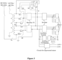
Figure 3 shows a structural schematic diagram of a multi-current power conversion system for a train according to a second embodiment of the present disclosure. - The core of the present disclosure is to provide a multi-current power conversion system for a train that can support at least four grid voltage systems.
- In order to make the solution of the present disclosure better understood by those skilled in the art, the embodiments are described in detail with reference to the accompanying drawings and specific embodiments.
- Reference is made to
Figure 1 , which shows a structural schematic diagram of a multi-current power conversion system for a train. The multi-current power conversion system for a train includes atransformation module 10, aninductor module 20, atarget switching unit 30, atarget switch 40, arectifier 50, a first capacitor C, and a post-circuit 60. - The
transformation module 10 has a first input terminal connected to an AC input and a second input terminal connected to a DC input. Thetransformation module 10 is configured to output, when receiving an alternating-current power of any voltage level, an alternating-current power of a fixed voltage level to therectifier 50 via a first output terminal and a second output terminal of thetransformation module 10. Thetransformation module 10 is also configured to output, when receiving an direct-current power, the received direct-current power to a second terminal of theinductor module 20 via a third output terminal of thetransformation module 10. The number of types of the AC power is N, and the number of types of the DC power is M, and N≥2, M≥2. - It is understood that, in the present disclosure, the
transformation module 10 receives alternating-current power with different voltages at different times, not at the same time. The same is true for direct-current power. - The
transformation module 10 receives the AC input via the first input terminal. For example, the first input terminal is used to receive the two inputs of AC25kV and AC15kV as shown inFigure 1 . Thetransformation module 10 receives the DC input via the second input terminal. For example, the second input terminal is used to receive the two inputs of DC3000V and DC1500V as shown inFigure 1 . InFigure 1 , in order to distinguish the terminals, "1 input" refers to the first input terminal of thetransformation module 10, "2 input" refers to the second input terminal of thetransformation module 10, "1 output" refers to the first output terminal of thetransformation module 10, "2 output" refers to the second output terminal of thetransformation module 10, and "3 output" refers to the third output terminal of thetransformation module 10. For theinductor module 20, "1", "2", and "3" respectively refer to the first terminal, the second terminal, and the third terminal of theinductor module 20. - For received alternating-current power with different voltage levels, the
transformation module 10 can regulate the states of its devices so that the first output terminal and the second output terminal of thetransformation module 10, used as the output terminals for alternating-current power, can output alternating-current power with a fixed voltage level to arectifier 50. When direct-current power is received, thetransformation module 10 does not change the voltage level of the received direct-current power, but directly output the direct-current power via the third output terminal of thetransformation module 10. It should be noted that when direct-current power are received, thetransformation module 10 generally keeps a state of disconnection between its first output terminal and its second input terminal, and also a state of disconnection between its second output terminal and its second input terminal. - The
inductor module 20 has a first terminal connected to a first output terminal of therectifier 50, a second terminal connected to a first terminal of the first capacitor and the third output terminal of thetransformation module 10, and a third terminal connected to a first terminal of thetarget switching unit 30. Theinductor module 20 is configured to, when the transformation module receives k th alternating-current power, connect its first terminal to its second terminal, and regulate an equivalent inductance between its first terminal and its second terminal to a preset equivalent inductance corresponding to the k th alternating-current power, where k is an integer and N≥k≥1. Theinductor module 20 is also configured to, when the transformation module receives the direct-current power, break the connection between its first terminal and its second terminal, and connect its second terminal to its third terminal. - In practice, different grid voltage systems may have different voltage frequencies, in addition to different voltage levels. Thus, for different types of AC inputs, corresponding filter circuits should be provided in the intermediate circuit for filtering. The requirements for filtering different types of AC inputs are met by regulating the
inductor module 20 in the solution of the present disclosure. When thetransformation module 10 receives k th alternating-current power, theinductor module 20 connects its first terminal to its second terminal and regulates an equivalent inductance between its first terminal and its second terminal to a preset equivalent inductance corresponding to the k th alternating-current power, so that the filter circuit in the intermediate circuit meets the requirements for the alternating-current power with the frequency. In other words, for different received alternating-current power, the equivalent inductance between the first terminal and the second terminal of theinductor module 20 is different, so as to meet different filtering requirements for alternating-current power with different frequencies. - When the
transformation module 10 receives direct-current power, theinductor module 20 controls to break the connection between its first terminal and its second terminal and connects its second terminal to its third terminal so that the direct-current power is inputted from the second terminal of theinductor module 20 and outputted from the third terminal of theinductor module 20. - The specific structure of the
inductor module 20 can be designed according to actual needs, as long as it can meet the requirements of the solution of the present disclosure. - The
target switch 40 has a first terminal connected to a second output terminal of therectifier 50 and a second terminal connected to ground. - Both the
target switch 40 and thetarget switching unit 30 may be commonly used switching devices. For example, they may both be isolating switches. That is, the switch and the switching unit are not necessarily to be of different switch forms. - The first capacitor C has a second terminal connected to the second output terminal of the
rectifier 50. - The type and specific parameters of the first capacitor C can be designed according to actual needs. For example, the first capacitor C is implemented as an electrolytic capacitor suitable for high-voltage occasions. In the alternating current mode, the first capacitor C and the
inductor module 20 serve as an intermediate filter circuit to filter the output of therectifier 50. - The post-circuit 60 has a first output terminal connected to the first output terminal of the
rectifier 50 and a second terminal connected to the second output terminal of therectifier 50. The post-circuit 60 is configured to supply power to a load. - The specific structure of the post-circuit 60 can be designed as an existing post-circuit, which may usually be an inverter circuit. In the solution of the present disclosure, the post-circuit 60 is not required to be changed.
- The
target switching unit 30 has a second terminal connected to the second input terminal of therectifier 50. Both thetarget switch 40 and thetarget switching unit 30 are turned on only when thetransformation module 10 receives direct-current power. - The
rectifier 50 is configured to control, for different direct-current power received by thetransformation module 10, the on/off state of switching devices of therectifier 50 according to a rule, to provide the a voltage of a fixed level to the post-circuit 60. - When the
transformation module 10 receives direct-current power, thetarget switching unit 30 is turned on so that the direct-current power can be input to the second input terminal of therectifier 50 via thetarget switching unit 30. When thetarget switch 40 is connected to the ground, therectifier 50 and theinductor module 20 form a boost circuit. By controlling the on/off state of switching devices in therectifier 50, i.e. regulating the duty cycle, the boost ratio can be regulated so that, for different direct-current power received by thetransformation module 10, the voltage of the fixed level is provided to the post-circuit 60. If the voltage of the direct-current power received by thetransformation module 10 is large power meeting the voltage requirements for the post-circuit 60, therectifier 50 may be controlled not to boost the voltage. - In the solution of the present disclosure, for different received alternating-current power or direct-current power, states of only the
transformation module 10, theinductor module 20, thetarget switching unit 30, and thetarget switch 40 are regulated, and the specification of therectifier 50 and the post-circuit 60 do not have to be changed. That is, a same specification of therectifier 50 and the post-circuit 60 can be applied to at least four grid voltage systems. - With the technical solution provided by the embodiments of the present disclosure, at least two DC grid voltage systems and at least two AC grid voltage systems can be supported. For various alternating-current power with different voltage levels received by the transformation module, the transformation module can output, via its first and second output terminals, alternating-current power with the fixed voltage level to the rectifier, so that a voltage of a fixed level is applied to the post-circuit. When receiving alternating-current power, the inductor module connects its first terminal to its second terminal and regulates an equivalent inductance between its first and second terminals to a preset equivalent inductance corresponding to the alternating-current power, which means that the intermediate filter circuit meets the requirements of the current voltage. When receiving direct-current power, the transformation module outputs, via its third output terminal, the direct-current power to the second terminal of the inductor module. At this time, the second terminal of the inductor module is connected to the third terminal of the inductor module, and therefore the direct-current power is inputted into the rectifier via the target switching unit. The voltage provided to the post-circuit is controlled to be unchanged by controlling the on/off states of controllable switches of the rectifier. Thus, the solution of the present disclosure supports at least four types of grid voltage systems.
- In an embodiment of the present disclosure, referring to
Figure 2 , thetransformation module 10 includes atraction transformer 11 and N+1 switches. - A first terminal of a primary winding of the
traction transformer 11 functions as the first input terminal of thetransformation module 10 and is connected to the AC input. A second terminal of the primary winding of thetraction transformer 11 is connected to the ground. A secondary winding of thetraction transformer 11 is arranged sequentially with N+1 terminals. The N+1th terminal of the secondary winding functions as the second input terminal of thetransformation module 10. The 1st terminal of the secondary winding functions as the third output terminal of thetransformation module 10. The 1st terminal of the secondary winding and the first terminal of the primary winding are homonymous terminals of thetraction transformer 11. - In the N+1 switches, a first terminal of a 1st switch Q1 is connected to the 1st terminal of the secondary winding, and a second terminal of the 1st switch Q1 functions as the first output terminal of the
transformation module 10, and is used to connect to the first input terminal of therectifier 50. A first terminal of an i th switch is connected to the i th terminal of the secondary winding, and a second terminal of the i th switch is connected to the second input terminal of therectifier 50, where i is an integer and 2≤i≤N+1. - Voltages of the 1st to the N th types of alternating-current power received by the
transformation module 10 sequentially decreases. The 1st switch Q1 is turned on only when alternating-current power is received by thetraction transformer 11, and the i th switch is turned on only when the i-1th alternating-current power is received by thetraction transformer 11. - In the embodiment in
Figure 2 , the secondary winding is arranged with N+1 output terminals, which is sequentially referred to as the 1st terminal, the 2nd terminal, ..., and the N+1th terminal of the secondary winding. The 1st terminal of the secondary winding and the first terminal of the primary winding are homonymous terminals of thetraction transformer 11, and correspondingly, the N+1th terminal of the secondary winding and the second terminal of the primary winding are homonymous terminals of thetraction transformer 11. When receiving alternating-current power with a voltage, the voltage between the 1st and 2nd terminals of the secondary winding is the lowest, the voltage between the 1st and 3rd terminals of the secondary winding is the second lowest, and the voltage between the 1st and N+1th terminals of the secondary winding is the highest. - The 1st switch Q1 is connected to the 1st terminal of the secondary winding and the first input terminal of the
rectifier 50. When alternating-current power is received, the 1st switch Q1 remains a turned-on state. The 2nd switch Q2 to the N+1th switch QN+1 are each connected to the corresponding terminal of the secondary winding and are all connected to the second input terminal of therectifier 50. - In this embodiment, the N types of alternating-current power are sequentially referred to as 1st alternating-current power, 2nd alternating-current power,..., and N th alternating-current power in a descending order of their voltage levels. That is, the voltage of the 1st alternating-current power is the highest, and the voltage of the N th alternating-current power is the lowest. When the 1st alternating-current power is received, the 1st switch Q1 and the 2nd switch Q2 are turned on, and the 3rd switch Q3 to the N+1th switch QN+1 are all turned off. When the 2nd alternating-current power is received, among the N+1 switches, the 1st switch Q1 and the 3rd switch Q3 are turned on and the other switches are turned off. That is, when the i-1th alternating-current power is received, among the N+1 switches, only the 1st switch Q1 and the i th switch are turned on, where i is an integer and 2≤i≤N+1.
- In practices, the specific number of the secondary winding terminals and the position on the secondary winding of each terminal can be designed according to actual situations. Generally, the secondary winding terminals are designed according to the respective voltages of the N types of alternating-current power supported by the train. In this embodiment, the regulation of voltages of different alternating-current power is realized through the N+1 switches, which is simple and convenient to implement.
- In an embodiment of the present disclosure, the
inductor module 20 may include N inductor units and N switching units. - Among the N inductor units, a second terminal of a j th inductor unit is connected to a first terminal of a j-1th inductor unit, where j is an integer and 2≤j≤N. A second terminal of a 1st inductor unit G1 functions as the second terminal of the
inductor module 20. A first terminal of an N th inductor unit GN functions as the third terminal of theinductor module 20. - Among the N switching units, a first terminal of an m th switching unit is connected to a first terminal of the m th inductor unit, and a second terminal of the m th switching unit is connected to the first output terminal of the
rectifier 50, where m is an integer and 1≤m≤N. The m th switching unit is turned on only when the m th alternating-current power is received by thetransformation module 10. - In this embodiment, N inductor units are connected in series, and the equivalent inductance between the first terminal and the second terminal of the
inductor module 20 is changed through turning on or off the N switching units. Specifically, when the 1st alternating-current power is received, among the N switching units, only the 1st switching unit q1 is turned on. At this time, the equivalent inductance between the first terminal and the second terminal of theinductor module 20 is the equivalent inductance of the 1st inductor unit. When the 2nd alternating-current power is received, among the N switching units, only the 2nd switching unit q2 is turned on. At this time, the equivalent inductance between the first terminal and the second terminal of theinductor module 20 is the sum of the equivalent inductance of the 1st inductor unit G1 and the equivalent inductance of the 2nd inductor unit G2. - The internal structure of each inductor unit can be designed according to actual needs, which may be simply one inductor, or may be a combination of multiple inductors. For example, the inductor L2 and the inductor L3 can be regarded as the second inductor unit G2 in the implementation of
Figure 3 . The N switching units may generally be isolating switches. - It should be noted that a specific method for regulating the on/off state of the N switching units is described in this embodiment. In other embodiments, the on/off state of each switching unit can be controlled according to different frequencies of the received alternating-current power. In addition, other switching forms can be used to control the
inductor module 20. That is, the specific structure of theinductor module 20 can be implemented in other ways, as long as the state of theinductor module 20 can meet the requirements on the inductance in the filter circuit for different received alternating-current power. - In an embodiment of the present disclosure, the N switches and the
target switch 40 may all be arranged in a first isolating switch box, and the N switching units and thetarget switching unit 30 may all be arranged in a second isolating switch box, so as to facilitate the control of the on/off state of each switching unit and each switch. With this configuration, the external interface of the traction converter form by therectifier 50 and the post-circuit 60 does not need to be changed. That is, the traction converter itself does not have a state switch, which is convenient for implementation. - Further, the
traction transformer 11 and the traction converter are generally installed at the bottom of different carriages, leading to a long distance. Therefore, the first isolating switch box and the second isolating switch box may be arranged at the carriage where thetraction transformer 11 is located, so as to shorten the length of electrical wires, reduce the difficulty of wiring, and improve the electromagnetic compatibility of the whole train. - In an embodiment of the present disclosure, referring to
Figure 3 , the system further includes an auxiliary inverter circuit having a first input terminal connected to the first output terminal of therectifier 50 and a second input terminal connected to the second output terminal of therectifier 50. - The auxiliary inverter circuit may include an auxiliary inverter and an auxiliary transformer, configured to convert the direct-current power into a three-phase alternating-current power of variable frequency and variable voltage, to supply power to an auxiliary load of the train.
- In an embodiment of the present disclosure, the system may further include a circuit for unpowered return. The circuit for unpowered return has a first input terminal connected to the first output terminal of the
rectifier 50 and a second input terminal connected to the second output terminal of therectifier 50. The circuit for unpowered return is generally used for achieving the function of unpowered return under a rescue mode. - It should be noted that, in the embodiment shown in
Figure 3 , the train power conversion system includes tworectifiers 50 and the post-circuits respectively connected to therectifiers 50. That is, two power supply systems are provide, with some devices being reused. For example, it is not necessary to arrange two transformation modules, but only one double-secondary-winding traction transformer may be arranged, having three output terminals at each secondary winding. The two power supply systems can share one inductor module which includes an inductor L1, an inductor L2, an inductor L3, a switch S5, a switch S6, and a switch S7. - It should further be noted that, in this embodiment, the inductor L2 and the inductor L3may be replaced by only one inductor. That is, a terminal of the inductor is connected to the inductor L1 and the other terminal of the inductor is connected to the second input terminals of both the two
rectifiers 50. The embodiment shown inFigure 3 is equivalent to separately arranging DC circuits for the two power supply systems. That is, by individually controlling the on/off states of S3 and S4, the on/off state of the DC circuits can be individually controlled. In addition, an isolating switch S2 is added since two secondary windings are used. The isolating switch S2 is turned off when alternating-current power is received, and is turned on when direct-current power is received. In the embodiment shown inFigure 3 , N and Mboth are equal to 2. Further, inFigure 3 , a switch S1 is arranged on the DC power supply circuit, to control the on/off state of the DC input. - Among the 14 isolating switches in
Figure 3 , i.e., S1, S2, S3, S4, S5, S6, S7, S8, S21, S22, S23, S11, S12, S13, when the train receives an AC25kV/50Hz input, the isolating switches S11, S12, S21, S22, and S7 are turned on and the other switches are turned off. The suitable secondary winding is selected by turning on S12 and S22. The suitable secondary resonance inductance is selected by turning on S7. The AC voltage of the secondary winding is rectified and then output to the intermediate circuit. The intermediate circuit eliminates the second harmonic of the intermediate voltage. The inverter converts the direct-current power into a three-phase alternating-current power to supply power to the traction motor. The auxiliary inverter converts the direct-current power into a variable-frequency and variable-voltage three-phase alternating-current power to supply power to the auxiliary load of the train. When the train receives an AC15kV/16.7Hz input, the isolating switches S11, S13, S21, S23, S5, and S6 are turned on and the others of the 14 isolating switches are turned off. - When the train receives an input of either DC3000V or DC1500V, among the 14 isolating switches, the isolating switches S1, S2, S3, S4, and S8 are turned on and the others are turned off. The grid voltage is input to the
rectifier 50 through the secondary winding and a secondary filter reactor, and then flows into the intermediate circuit through therectifier 50. The inverter converts the direct-current power into a variable-frequency and variable-voltage three-phase alternating-current power to supply power to the traction motor. The auxiliary inverter converts the direct-current power into a constant frequency and constant voltage alternating-current power to supply power to the auxiliary load of the train. The secondary filter reactor described here is the equivalent reactance formed by L1, L2 and L3. - When the train receives a DC3000V input, the
rectifier 50 may not boost the DC input. However, when the train receives a DC1500V input, by controlling the switching devices in therectifier 50, therectifier 50 realizes the function of boosting and chopping, so as to increase the intermediate voltage to DC3000V to supply power to the inverter. - Considering that the
rectifier 50 of the present disclosure cooperates with the secondary filter reactor to achieve voltage boosting, therectifier 50 may generally be a four-quadrant rectifier 50. Furthermore, the four-quadrant rectifier 50 is preferably a PWM four-quadrant rectifier 50. - The embodiments of the present disclosure also provide a train, which may include the multi-current power conversion system for a train in any of the foregoing embodiments. Reference may be made to the above embodiments for details of the train, which is not repeated here.
Claims (9)
- A multi-current power conversion system for use with
a train, comprising:a transformation module (10), having a first input terminal connected to an alternating-current input and a second input terminal connected a direct-current input, wherein the transformation module (10) is configured to, for received alternating-current power of different voltage levels, output alternating-current power of a fixed voltage level to a rectifier (50) via a first output terminal and a second output terminal, and for received direct-current power, output the received direct-current power to a second terminal of an inductor module (20) via a third output terminal; wherein a number of types of the alternating-current power is N, a number of types of the direct-current power is M, and N≥2, M≥2;the inductor module (20), having a first terminal connected to a first output terminal of the rectifier (50), a second terminal connected to a first terminal of a first capacitor and the third output terminal of the transformation module (10), and a third terminal connected to a first terminal of a target switching unit (30), wherein the inductor module (20) is configured to, when the transformation module (10) receives k th alternating-current power, connect a first terminal of the inductor module (20) to the second terminal of the inductor module (20), and regulate an equivalent inductance between the first terminal of the inductor module (20) and the second terminal of the inductor module (20) to a preset equivalent inductance corresponding to the k th alternating-current power, wherein k is an integer and N≥k≥1;a target switch (40), having a first terminal connected to a second output terminal of the rectifier (50) and a second terminal connected to ground;the first capacitor, having a second terminal connected to the second output terminal of the rectifier (50);a post-circuit (60), having a first input terminal connected to the first output terminal of the rectifier (50) and a second input terminal connected to the second output terminal of the rectifier (50), and the post-circuit (60) is configured to supply power to a load;the target switching unit (30), having a second terminal connected to a second input terminal of the rectifier (50), wherein the target switch (40) and the target switching unit (30) are turned on only when the transformation module (10) receives the direct-current power; andthe rectifier (50), configured to, for different direct-current power received by the transformation module (10), control an on/off state of a switching device of the rectifier (50) according to a rule, to provide a voltage of a fixed level to the post-circuit (60),wherein the transformation module (10) comprises:a traction transformer, wherein a first terminal of a primary winding of the traction transformer functions as the first input terminal of the transformation module (10) and is connected to the alternating-current input, a second terminal of the primary winding is connected to ground, and a secondary winding of the traction transformer is arranged sequentially with N+1 terminals; andN+1 switches respectively connected to the N+1 terminals of the secondary winding of the traction transformer,characterized in that:the inductor module (20) is also configured to, in a case that the transformation module (10) receives the M types of the direct-current power, disconnect the first terminal of the inductor module (20) from the second terminal of the inductor module (20), and connect the second terminal of the inductor module (20) to the third terminal of the inductor module (20);the N+1th terminal of the secondary winding functions as the second input terminal of the transformation module (10) and is connected the direct-current input, the 1st terminal of the secondary winding functions as the third output terminal of the transformation module (10), the 1st terminal of the secondary winding and the first terminal of the primary winding are homonymous terminals of the traction transformer;wherein a first terminal of a 1st switch is connected to the 1st terminal of the secondary winding, a second terminal of the 1st switch functions as the first output terminal of the transformation module (10), and is connect to the first input terminal of the rectifier (50), a first terminal of an i th switch is connected to the i th terminal of the secondary winding, and a second terminal of the i th switch is connected to the second input terminal of the rectifier (50), wherein i is an integer and 2≤i≤N+1; andvoltages of first to Nth types of alternating-current power received by the transformation module (10) sequentially decreases, and the 1st switch is turned on only when the alternating-current power is received by the traction transformer, and the i th switch is turned on only when the i-1th type of alternating-current power is received by the traction transformer. - The multi-current power conversion system for use with a train according to claim 1, wherein the
inductor module (20) comprises:N inductor units, wherein a second terminal of a j th inductor unit is connected to a first terminal of a j-1th inductor unit, wherein j is an integer and 2≤j≤N; a second terminal of a 1st inductor unit functions as the second terminal of the inductor module (20); a first terminal of a N th inductor unit functions as the third terminal of the inductor module (20); andN switching units, wherein a first terminal of an m th switching unit is connected to a first terminal of an m th inductor unit, and a second terminal of the m th switching unit is connected to the first output terminal of the rectifier (50), where m is an integer and 1≤m≤N; the m th switching unit is turned on only when the m th type of alternating-current power is received by the transformation module (10). - The multi-current power conversion system for use with a train according to claim 2, wherein N
of the switches and the target switch (40) are all arranged in a first isolating switch box, and the N switching units and the target switching unit (30) are all arranged in a second isolating switch box. - The multi-current power conversion system for use with a train according to claim 1, wherein N
is equal to 2 and M is equal to 2. - The multi-current power conversion system for use with a train according to claim 1, further
comprising:
an auxiliary inverter circuit having a first input terminal connected to the first output terminal of the rectifier (50) and a second input terminal connected to the second output terminal of the rectifier (50). - The multi-current power conversion system for use with a train according to claim 5, further comprising:
a circuit for unpowered return, having a first input terminal connected to the first output terminal of the rectifier (50) and a second input terminal connected to the second output terminal of the rectifier (50). - The multi-current power conversion system for use with a train according to any one of claims 1
to 6, wherein the rectifier (50) is a four-quadrant rectifier (50). - The multi-current power conversion system for use with a train according to claim 7, wherein the
four-quadrant rectifier (50) is a PWM four-quadrant rectifier (50). - A train, comprising the multi-current power conversion system for a train according to any one of claims 1 to 8.
Applications Claiming Priority (2)
| Application Number | Priority Date | Filing Date | Title |
|---|---|---|---|
| CN201811511592.8A CN111313718A (en) | 2018-12-11 | 2018-12-11 | Train and train converter system with multiple systems |
| PCT/CN2019/113011 WO2020119273A1 (en) | 2018-12-11 | 2019-10-24 | Train and multi-current power conversion system thereof |
Publications (3)
| Publication Number | Publication Date |
|---|---|
| EP3842276A1 EP3842276A1 (en) | 2021-06-30 |
| EP3842276A4 EP3842276A4 (en) | 2022-05-11 |
| EP3842276B1 true EP3842276B1 (en) | 2025-03-05 |
Family
ID=71077104
Family Applications (1)
| Application Number | Title | Priority Date | Filing Date |
|---|---|---|---|
| EP19895349.9A Active EP3842276B1 (en) | 2018-12-11 | 2019-10-24 | Train and multi-current power conversion system thereof |
Country Status (3)
| Country | Link |
|---|---|
| EP (1) | EP3842276B1 (en) |
| CN (1) | CN111313718A (en) |
| WO (1) | WO2020119273A1 (en) |
Families Citing this family (1)
| Publication number | Priority date | Publication date | Assignee | Title |
|---|---|---|---|---|
| CN115834624B (en) * | 2022-11-18 | 2026-03-27 | 中车株洲电机有限公司 | A traction transformer control cabinet and railcar |
Citations (3)
| Publication number | Priority date | Publication date | Assignee | Title |
|---|---|---|---|---|
| DE102008014571A1 (en) | 2008-03-13 | 2009-09-17 | Siemens Aktiengesellschaft | Motor drive circuit for a rail vehicle and method for its operation |
| WO2015055457A2 (en) | 2013-10-16 | 2015-04-23 | Siemens Aktiengesellschaft | Multi-system power converter arrangement |
| CN107627862A (en) | 2016-07-19 | 2018-01-26 | 株洲中车时代电气股份有限公司 | A kind of multithread convertor equipment |
Family Cites Families (6)
| Publication number | Priority date | Publication date | Assignee | Title |
|---|---|---|---|---|
| CN103754123B (en) * | 2014-01-21 | 2016-03-30 | 湖南大学 | Based on multithread tractive power supply system and the method for single-phase Multiple coil traction transformer |
| CN204179953U (en) * | 2014-11-19 | 2015-02-25 | 株洲南车时代电气股份有限公司 | Traction converter plant and module |
| CN104553832B (en) * | 2014-11-28 | 2016-09-28 | 湖南大学 | The degaussing system and method for transformer core remanent magnetism based on LC Plus four quadrant convertor oscillation circuit |
| CN104477054B (en) * | 2014-11-28 | 2016-09-28 | 湖南大学 | A kind of multithread traction drive based on total power device and method |
| CN104467455A (en) * | 2014-12-04 | 2015-03-25 | 株洲南车时代电气股份有限公司 | Multi-system converter device |
| KR101957469B1 (en) * | 2016-12-29 | 2019-03-13 | 한국철도기술연구원 | Semiconductor Transformer for Railway Vehicle using Multiwinding High-frequency Transformer |
-
2018
- 2018-12-11 CN CN201811511592.8A patent/CN111313718A/en active Pending
-
2019
- 2019-10-24 WO PCT/CN2019/113011 patent/WO2020119273A1/en not_active Ceased
- 2019-10-24 EP EP19895349.9A patent/EP3842276B1/en active Active
Patent Citations (4)
| Publication number | Priority date | Publication date | Assignee | Title |
|---|---|---|---|---|
| DE102008014571A1 (en) | 2008-03-13 | 2009-09-17 | Siemens Aktiengesellschaft | Motor drive circuit for a rail vehicle and method for its operation |
| WO2015055457A2 (en) | 2013-10-16 | 2015-04-23 | Siemens Aktiengesellschaft | Multi-system power converter arrangement |
| EP3019366B1 (en) * | 2013-10-16 | 2019-01-02 | Siemens Mobility GmbH | Precharge circuit for a multi-system power converter arrangement |
| CN107627862A (en) | 2016-07-19 | 2018-01-26 | 株洲中车时代电气股份有限公司 | A kind of multithread convertor equipment |
Non-Patent Citations (7)
| Title |
|---|
| ANONYMOUS: "Siemens Vectron", WIKIPEDIA, 21 October 2025 (2025-10-21), pages 1 - 26, XP093347895, Retrieved from the Internet <URL:https://de.wikipedia.org/w/index.php?title=Siemens_Vectron&oldid=260769838> |
| BECKER CHRISTIAN, KÖCK ALEXANDER: "Die Viersystem-Hochleistungslokomotive Eurosprinter ES 64 F4", EISENBAHN-REVUE INTERNATIONAL, vol. 2006, no. 2, 1 February 2006 (2006-02-01), pages 65 - 73, XP093347902, ISSN: 1421-2811 |
| D1 - SIEMENS AG; Schulung Stromrichter Vectron Mehsystemlok |
| D2 - SIEMENS Trainingszentrum, Unterschriftenliste |
| D4 - Lokauslieferungen |
| D6 - Affidavit Ulrich Wenkemann |
| SCHURIG J: "Die Mehrsystem Lokomotive ES64U4", EISENBAHN-REVUE INTERNATIONAL, vol. 07/2005, 1 July 2005 (2005-07-01), pages 333 - 336, XP009091818, ISSN: 1421-2811 |
Also Published As
| Publication number | Publication date |
|---|---|
| WO2020119273A1 (en) | 2020-06-18 |
| CN111313718A (en) | 2020-06-19 |
| EP3842276A4 (en) | 2022-05-11 |
| EP3842276A1 (en) | 2021-06-30 |
Similar Documents
| Publication | Publication Date | Title |
|---|---|---|
| KR101540018B1 (en) | Method for powering emergency auxiliary loads, auxiliary converter and railway vehicle by the method | |
| CN102271958B (en) | Method for controlling power supply device having power inverter | |
| US8009443B2 (en) | DC/DC converter and AC/DC converter | |
| KR100436534B1 (en) | Apparatus and Method for Supplying DC Power to Traction System | |
| EP2445747B1 (en) | Circuit arrangement for power distribution in a motor vehicle | |
| US10141858B2 (en) | Power converter for electric locomotive | |
| EP2695763B1 (en) | Traction power converter for multisystem rail vehicle | |
| EP2872359B1 (en) | Energy management system for railbound vehicles | |
| KR102730545B1 (en) | Electric power conversion system and control method therefor | |
| CN113412566A (en) | Integrated charging and motor control system including a transformer and a multilevel power converter | |
| CN111602329B (en) | Converter component and semiconductor module of such a converter component | |
| CN104485821A (en) | Direct current transformer device used for power distribution | |
| CN115023877A (en) | Integrated charger and motor control system isolated by motor | |
| EP3577754A1 (en) | Battery charger for traction vehicle | |
| CN103683983A (en) | Hybrid energy feedback type direct-current traction power supply device and control method | |
| EP2629413A1 (en) | Supply of electric power within in a track-bound electric vehicle by means of modular multilevel converters | |
| EP3842276B1 (en) | Train and multi-current power conversion system thereof | |
| CZ343197A3 (en) | Process and circuit arrangement of electric power transformation | |
| CN112886830A (en) | Auxiliary power supply conversion circuit for subway vehicle | |
| EP3581429B1 (en) | Traction converter with ac and dc operation modes | |
| CN1419251A (en) | Transformer and feed circuit for multi-system driving vehicle | |
| KR20240021120A (en) | Method and circuit for an integrated dc-dc converter in an ac battery | |
| US11309803B2 (en) | Power converter for trasmitting power between networks | |
| CN115333386A (en) | High-power helicopter starting DC power supply vehicle | |
| CN115498721A (en) | Charge-discharge integrated system |
Legal Events
| Date | Code | Title | Description |
|---|---|---|---|
| STAA | Information on the status of an ep patent application or granted ep patent |
Free format text: STATUS: THE INTERNATIONAL PUBLICATION HAS BEEN MADE |
|
| PUAI | Public reference made under article 153(3) epc to a published international application that has entered the european phase |
Free format text: ORIGINAL CODE: 0009012 |
|
| STAA | Information on the status of an ep patent application or granted ep patent |
Free format text: STATUS: REQUEST FOR EXAMINATION WAS MADE |
|
| 17P | Request for examination filed |
Effective date: 20210323 |
|
| AK | Designated contracting states |
Kind code of ref document: A1 Designated state(s): AL AT BE BG CH CY CZ DE DK EE ES FI FR GB GR HR HU IE IS IT LI LT LU LV MC MK MT NL NO PL PT RO RS SE SI SK SM TR |
|
| DAV | Request for validation of the european patent (deleted) | ||
| DAX | Request for extension of the european patent (deleted) | ||
| A4 | Supplementary search report drawn up and despatched |
Effective date: 20220412 |
|
| RIC1 | Information provided on ipc code assigned before grant |
Ipc: H02M 7/217 20060101ALI20220406BHEP Ipc: H02M 5/10 20060101ALI20220406BHEP Ipc: H02M 3/158 20060101ALI20220406BHEP Ipc: H02M 1/10 20060101ALI20220406BHEP Ipc: B60L 9/30 20060101ALI20220406BHEP Ipc: B60L 1/00 20060101ALI20220406BHEP Ipc: B60L 9/00 20190101AFI20220406BHEP |
|
| STAA | Information on the status of an ep patent application or granted ep patent |
Free format text: STATUS: EXAMINATION IS IN PROGRESS |
|
| 17Q | First examination report despatched |
Effective date: 20230126 |
|
| GRAP | Despatch of communication of intention to grant a patent |
Free format text: ORIGINAL CODE: EPIDOSNIGR1 |
|
| STAA | Information on the status of an ep patent application or granted ep patent |
Free format text: STATUS: GRANT OF PATENT IS INTENDED |
|
| INTG | Intention to grant announced |
Effective date: 20241024 |
|
| GRAS | Grant fee paid |
Free format text: ORIGINAL CODE: EPIDOSNIGR3 |
|
| GRAA | (expected) grant |
Free format text: ORIGINAL CODE: 0009210 |
|
| STAA | Information on the status of an ep patent application or granted ep patent |
Free format text: STATUS: THE PATENT HAS BEEN GRANTED |
|
| P01 | Opt-out of the competence of the unified patent court (upc) registered |
Free format text: CASE NUMBER: APP_244/2025 Effective date: 20250103 |
|
| AK | Designated contracting states |
Kind code of ref document: B1 Designated state(s): AL AT BE BG CH CY CZ DE DK EE ES FI FR GB GR HR HU IE IS IT LI LT LU LV MC MK MT NL NO PL PT RO RS SE SI SK SM TR |
|
| REG | Reference to a national code |
Ref country code: GB Ref legal event code: FG4D |
|
| REG | Reference to a national code |
Ref country code: CH Ref legal event code: EP |
|
| REG | Reference to a national code |
Ref country code: DE Ref legal event code: R096 Ref document number: 602019067039 Country of ref document: DE |
|
| REG | Reference to a national code |
Ref country code: IE Ref legal event code: FG4D |
|
| PG25 | Lapsed in a contracting state [announced via postgrant information from national office to epo] |
Ref country code: RS Free format text: LAPSE BECAUSE OF FAILURE TO SUBMIT A TRANSLATION OF THE DESCRIPTION OR TO PAY THE FEE WITHIN THE PRESCRIBED TIME-LIMIT Effective date: 20250605 |
|
| PG25 | Lapsed in a contracting state [announced via postgrant information from national office to epo] |
Ref country code: FI Free format text: LAPSE BECAUSE OF FAILURE TO SUBMIT A TRANSLATION OF THE DESCRIPTION OR TO PAY THE FEE WITHIN THE PRESCRIBED TIME-LIMIT Effective date: 20250305 |
|
| REG | Reference to a national code |
Ref country code: NL Ref legal event code: MP Effective date: 20250305 |
|
| PG25 | Lapsed in a contracting state [announced via postgrant information from national office to epo] |
Ref country code: ES Free format text: LAPSE BECAUSE OF FAILURE TO SUBMIT A TRANSLATION OF THE DESCRIPTION OR TO PAY THE FEE WITHIN THE PRESCRIBED TIME-LIMIT Effective date: 20250305 |
|
| REG | Reference to a national code |
Ref country code: LT Ref legal event code: MG9D |
|
| PG25 | Lapsed in a contracting state [announced via postgrant information from national office to epo] |
Ref country code: NO Free format text: LAPSE BECAUSE OF FAILURE TO SUBMIT A TRANSLATION OF THE DESCRIPTION OR TO PAY THE FEE WITHIN THE PRESCRIBED TIME-LIMIT Effective date: 20250605 |
|
| PG25 | Lapsed in a contracting state [announced via postgrant information from national office to epo] |
Ref country code: HR Free format text: LAPSE BECAUSE OF FAILURE TO SUBMIT A TRANSLATION OF THE DESCRIPTION OR TO PAY THE FEE WITHIN THE PRESCRIBED TIME-LIMIT Effective date: 20250305 |
|
| PG25 | Lapsed in a contracting state [announced via postgrant information from national office to epo] |
Ref country code: LV Free format text: LAPSE BECAUSE OF FAILURE TO SUBMIT A TRANSLATION OF THE DESCRIPTION OR TO PAY THE FEE WITHIN THE PRESCRIBED TIME-LIMIT Effective date: 20250305 |
|
| PG25 | Lapsed in a contracting state [announced via postgrant information from national office to epo] |
Ref country code: GR Free format text: LAPSE BECAUSE OF FAILURE TO SUBMIT A TRANSLATION OF THE DESCRIPTION OR TO PAY THE FEE WITHIN THE PRESCRIBED TIME-LIMIT Effective date: 20250606 Ref country code: BG Free format text: LAPSE BECAUSE OF FAILURE TO SUBMIT A TRANSLATION OF THE DESCRIPTION OR TO PAY THE FEE WITHIN THE PRESCRIBED TIME-LIMIT Effective date: 20250305 |
|
| PG25 | Lapsed in a contracting state [announced via postgrant information from national office to epo] |
Ref country code: NL Free format text: LAPSE BECAUSE OF FAILURE TO SUBMIT A TRANSLATION OF THE DESCRIPTION OR TO PAY THE FEE WITHIN THE PRESCRIBED TIME-LIMIT Effective date: 20250305 |
|
| PG25 | Lapsed in a contracting state [announced via postgrant information from national office to epo] |
Ref country code: SE Free format text: LAPSE BECAUSE OF FAILURE TO SUBMIT A TRANSLATION OF THE DESCRIPTION OR TO PAY THE FEE WITHIN THE PRESCRIBED TIME-LIMIT Effective date: 20250305 |
|
| PG25 | Lapsed in a contracting state [announced via postgrant information from national office to epo] |
Ref country code: SM Free format text: LAPSE BECAUSE OF FAILURE TO SUBMIT A TRANSLATION OF THE DESCRIPTION OR TO PAY THE FEE WITHIN THE PRESCRIBED TIME-LIMIT Effective date: 20250305 |
|
| PG25 | Lapsed in a contracting state [announced via postgrant information from national office to epo] |
Ref country code: PT Free format text: LAPSE BECAUSE OF FAILURE TO SUBMIT A TRANSLATION OF THE DESCRIPTION OR TO PAY THE FEE WITHIN THE PRESCRIBED TIME-LIMIT Effective date: 20250707 |
|
| PG25 | Lapsed in a contracting state [announced via postgrant information from national office to epo] |
Ref country code: IT Free format text: LAPSE BECAUSE OF FAILURE TO SUBMIT A TRANSLATION OF THE DESCRIPTION OR TO PAY THE FEE WITHIN THE PRESCRIBED TIME-LIMIT Effective date: 20250305 Ref country code: PL Free format text: LAPSE BECAUSE OF FAILURE TO SUBMIT A TRANSLATION OF THE DESCRIPTION OR TO PAY THE FEE WITHIN THE PRESCRIBED TIME-LIMIT Effective date: 20250305 |
|
| PG25 | Lapsed in a contracting state [announced via postgrant information from national office to epo] |
Ref country code: EE Free format text: LAPSE BECAUSE OF FAILURE TO SUBMIT A TRANSLATION OF THE DESCRIPTION OR TO PAY THE FEE WITHIN THE PRESCRIBED TIME-LIMIT Effective date: 20250305 |
|
| PGFP | Annual fee paid to national office [announced via postgrant information from national office to epo] |
Ref country code: CZ Payment date: 20250919 Year of fee payment: 7 |
|
| PG25 | Lapsed in a contracting state [announced via postgrant information from national office to epo] |
Ref country code: RO Free format text: LAPSE BECAUSE OF FAILURE TO SUBMIT A TRANSLATION OF THE DESCRIPTION OR TO PAY THE FEE WITHIN THE PRESCRIBED TIME-LIMIT Effective date: 20250305 |
|
| PG25 | Lapsed in a contracting state [announced via postgrant information from national office to epo] |
Ref country code: SK Free format text: LAPSE BECAUSE OF FAILURE TO SUBMIT A TRANSLATION OF THE DESCRIPTION OR TO PAY THE FEE WITHIN THE PRESCRIBED TIME-LIMIT Effective date: 20250305 |
|
| PG25 | Lapsed in a contracting state [announced via postgrant information from national office to epo] |
Ref country code: IS Free format text: LAPSE BECAUSE OF FAILURE TO SUBMIT A TRANSLATION OF THE DESCRIPTION OR TO PAY THE FEE WITHIN THE PRESCRIBED TIME-LIMIT Effective date: 20250705 |
|
| REG | Reference to a national code |
Ref country code: DE Ref legal event code: R026 Ref document number: 602019067039 Country of ref document: DE |
|
| PLBI | Opposition filed |
Free format text: ORIGINAL CODE: 0009260 |
|
| PLAB | Opposition data, opponent's data or that of the opponent's representative modified |
Free format text: ORIGINAL CODE: 0009299OPPO |
|
| PLAX | Notice of opposition and request to file observation + time limit sent |
Free format text: ORIGINAL CODE: EPIDOSNOBS2 |
|
| 26 | Opposition filed |
Opponent name: SIEMENS MOBILITY GMBH Effective date: 20251204 |
|
| PG25 | Lapsed in a contracting state [announced via postgrant information from national office to epo] |
Ref country code: DK Free format text: LAPSE BECAUSE OF FAILURE TO SUBMIT A TRANSLATION OF THE DESCRIPTION OR TO PAY THE FEE WITHIN THE PRESCRIBED TIME-LIMIT Effective date: 20250305 |
|
| PGFP | Annual fee paid to national office [announced via postgrant information from national office to epo] |
Ref country code: AT Payment date: 20251024 Year of fee payment: 7 |
|
| R26 | Opposition filed (corrected) |
Opponent name: SIEMENS MOBILITY GMBH Effective date: 20251204 |