EP3841245B1 - System and method for treating biomass material - Google Patents
System and method for treating biomass material Download PDFInfo
- Publication number
- EP3841245B1 EP3841245B1 EP19852122.1A EP19852122A EP3841245B1 EP 3841245 B1 EP3841245 B1 EP 3841245B1 EP 19852122 A EP19852122 A EP 19852122A EP 3841245 B1 EP3841245 B1 EP 3841245B1
- Authority
- EP
- European Patent Office
- Prior art keywords
- stage
- filtrate
- biomass material
- liquid
- reactor
- Prior art date
- Legal status (The legal status is an assumption and is not a legal conclusion. Google has not performed a legal analysis and makes no representation as to the accuracy of the status listed.)
- Active
Links
Images


Classifications
-
- D—TEXTILES; PAPER
- D21—PAPER-MAKING; PRODUCTION OF CELLULOSE
- D21C—PRODUCTION OF CELLULOSE BY REMOVING NON-CELLULOSE SUBSTANCES FROM CELLULOSE-CONTAINING MATERIALS; REGENERATION OF PULPING LIQUORS; APPARATUS THEREFOR
- D21C1/00—Pretreatment of the finely-divided materials before digesting
- D21C1/04—Pretreatment of the finely-divided materials before digesting with acid reacting compounds
-
- C—CHEMISTRY; METALLURGY
- C12—BIOCHEMISTRY; BEER; SPIRITS; WINE; VINEGAR; MICROBIOLOGY; ENZYMOLOGY; MUTATION OR GENETIC ENGINEERING
- C12P—FERMENTATION OR ENZYME-USING PROCESSES TO SYNTHESISE A DESIRED CHEMICAL COMPOUND OR COMPOSITION OR TO SEPARATE OPTICAL ISOMERS FROM A RACEMIC MIXTURE
- C12P7/00—Preparation of oxygen-containing organic compounds
- C12P7/02—Preparation of oxygen-containing organic compounds containing a hydroxy group
- C12P7/04—Preparation of oxygen-containing organic compounds containing a hydroxy group acyclic
- C12P7/06—Ethanol, i.e. non-beverage
- C12P7/08—Ethanol, i.e. non-beverage produced as by-product or from waste or cellulosic material substrate
- C12P7/10—Ethanol, i.e. non-beverage produced as by-product or from waste or cellulosic material substrate substrate containing cellulosic material
-
- C—CHEMISTRY; METALLURGY
- C12—BIOCHEMISTRY; BEER; SPIRITS; WINE; VINEGAR; MICROBIOLOGY; ENZYMOLOGY; MUTATION OR GENETIC ENGINEERING
- C12M—APPARATUS FOR ENZYMOLOGY OR MICROBIOLOGY; APPARATUS FOR CULTURING MICROORGANISMS FOR PRODUCING BIOMASS, FOR GROWING CELLS OR FOR OBTAINING FERMENTATION OR METABOLIC PRODUCTS, i.e. BIOREACTORS OR FERMENTERS
- C12M21/00—Bioreactors or fermenters specially adapted for specific uses
- C12M21/12—Bioreactors or fermenters specially adapted for specific uses for producing fuels or solvents
-
- C—CHEMISTRY; METALLURGY
- C12—BIOCHEMISTRY; BEER; SPIRITS; WINE; VINEGAR; MICROBIOLOGY; ENZYMOLOGY; MUTATION OR GENETIC ENGINEERING
- C12M—APPARATUS FOR ENZYMOLOGY OR MICROBIOLOGY; APPARATUS FOR CULTURING MICROORGANISMS FOR PRODUCING BIOMASS, FOR GROWING CELLS OR FOR OBTAINING FERMENTATION OR METABOLIC PRODUCTS, i.e. BIOREACTORS OR FERMENTERS
- C12M45/00—Means for pre-treatment of biological substances
- C12M45/06—Means for pre-treatment of biological substances by chemical means or hydrolysis
-
- C—CHEMISTRY; METALLURGY
- C12—BIOCHEMISTRY; BEER; SPIRITS; WINE; VINEGAR; MICROBIOLOGY; ENZYMOLOGY; MUTATION OR GENETIC ENGINEERING
- C12P—FERMENTATION OR ENZYME-USING PROCESSES TO SYNTHESISE A DESIRED CHEMICAL COMPOUND OR COMPOSITION OR TO SEPARATE OPTICAL ISOMERS FROM A RACEMIC MIXTURE
- C12P7/00—Preparation of oxygen-containing organic compounds
- C12P7/02—Preparation of oxygen-containing organic compounds containing a hydroxy group
- C12P7/04—Preparation of oxygen-containing organic compounds containing a hydroxy group acyclic
- C12P7/06—Ethanol, i.e. non-beverage
- C12P7/08—Ethanol, i.e. non-beverage produced as by-product or from waste or cellulosic material substrate
-
- D—TEXTILES; PAPER
- D21—PAPER-MAKING; PRODUCTION OF CELLULOSE
- D21C—PRODUCTION OF CELLULOSE BY REMOVING NON-CELLULOSE SUBSTANCES FROM CELLULOSE-CONTAINING MATERIALS; REGENERATION OF PULPING LIQUORS; APPARATUS THEREFOR
- D21C1/00—Pretreatment of the finely-divided materials before digesting
- D21C1/02—Pretreatment of the finely-divided materials before digesting with water or steam
-
- C—CHEMISTRY; METALLURGY
- C12—BIOCHEMISTRY; BEER; SPIRITS; WINE; VINEGAR; MICROBIOLOGY; ENZYMOLOGY; MUTATION OR GENETIC ENGINEERING
- C12P—FERMENTATION OR ENZYME-USING PROCESSES TO SYNTHESISE A DESIRED CHEMICAL COMPOUND OR COMPOSITION OR TO SEPARATE OPTICAL ISOMERS FROM A RACEMIC MIXTURE
- C12P2201/00—Pretreatment of cellulosic or lignocellulosic material for subsequent enzymatic treatment or hydrolysis
-
- D—TEXTILES; PAPER
- D21—PAPER-MAKING; PRODUCTION OF CELLULOSE
- D21C—PRODUCTION OF CELLULOSE BY REMOVING NON-CELLULOSE SUBSTANCES FROM CELLULOSE-CONTAINING MATERIALS; REGENERATION OF PULPING LIQUORS; APPARATUS THEREFOR
- D21C9/00—After-treatment of cellulose pulp, e.g. of wood pulp, or cotton linters ; Treatment of dilute or dewatered pulp or process improvement taking place after obtaining the raw cellulosic material and not provided for elsewhere
- D21C9/18—De-watering; Elimination of cooking or pulp-treating liquors from the pulp
-
- Y—GENERAL TAGGING OF NEW TECHNOLOGICAL DEVELOPMENTS; GENERAL TAGGING OF CROSS-SECTIONAL TECHNOLOGIES SPANNING OVER SEVERAL SECTIONS OF THE IPC; TECHNICAL SUBJECTS COVERED BY FORMER USPC CROSS-REFERENCE ART COLLECTIONS [XRACs] AND DIGESTS
- Y02—TECHNOLOGIES OR APPLICATIONS FOR MITIGATION OR ADAPTATION AGAINST CLIMATE CHANGE
- Y02E—REDUCTION OF GREENHOUSE GAS [GHG] EMISSIONS, RELATED TO ENERGY GENERATION, TRANSMISSION OR DISTRIBUTION
- Y02E50/00—Technologies for the production of fuel of non-fossil origin
- Y02E50/10—Biofuels, e.g. bio-diesel
Definitions
- the present invention relates to feeding arrangements and systems for hydrolysis and pre-hydrolysis processes for production of biofuels such as ethanol using, e.g. biodegradable waste, or lignocellulosic biomass material including wood waste, e.g. saw dust, or plant material including annual plants.
- biofuels such as ethanol using, e.g. biodegradable waste, or lignocellulosic biomass material including wood waste, e.g. saw dust, or plant material including annual plants.
- Ethanol has been an alternative for gasoline for many years but has now become an increasingly important biofuel as source for motor fuel and fuel additive.
- Ethanol can be produced from biodegradable waste, e.g. food waste, grain-based feed stocks, e.g. corn, wheat, or soybeans, from sugar, e.g. from sugar beets, from biomass, lignocellulosic biomass material such as wood, or plant material including annual plants.
- the raw material is fed into a pre-hydrolysis reactor.
- the raw material can also be pre-steamed or pre-impregnated before being fed into the pre-hydrolysis reactor or other chemical reactor.
- an acidifying chemical e.g. H2SO4
- H2SO4 is added in a process stage up-stream the reactor, for example in an impregnation stage, in a soaking stage or in a mixer screw by spraying.
- the acidified material is then fed into the reactor using a feeding device, e.g. a plug screw feeder, and a major part of the liquid in the material is removed as filtrate.
- the filtrate is then recirculated in the process and used to impregnate or to spray raw material fed into the process together with acidifying chemicals.
- the amount of filtrate that is removed in the plug screw is higher than the amount of filtrate that is needed to acidify the raw material. Therefore, the remaining surplus filtrate is fed into the pre-hydrolysis reactor, or other chemical reactor in the process.
- this surplus filtrate contains acidifying chemicals which results in inter alia corrosion in the reactor and negative effects in the process itself within the reactor if filtrate containing acidifying chemical is sprayed on the surface of the raw material. For example, it may result in a faster reaction at the surface of the material.
- An object of the present invention is to provide improved processes and systems for treating biomass in pre-hydrolysis systems for biofuel production.
- Another object of the present invention is to provide a more efficient handling of liquid and water in processes and systems for treating biomass in pre-hydrolysis systems for biofuel production.
- a further object of the present invention is to provide processes and systems for treating biomass in pre-hydrolysis systems for biofuel production where the wear such as corrosion can be significantly reduced in essential parts of the system such as the pre-hydrolysis reactor.
- Yet another object of the system is to provide processes and systems for treating biomass in pre-hydrolysis systems for biofuel production that are capable of using raw material with a high degree of moisture without affecting the balance of the system and with an efficient water usage.
- a treatment process system for biomass material comprising a first dewatering stage arranged to receive biomass material, to remove liquid from the biomass material, and to feed the biomass material forward in the process. Further, the system includes a first filtrate tank operatively coupled to the first dewatering stage and is arranged to collect the liquid removed in the first dewatering stage.
- An addition stage is located downstream the dewatering stage and is operatively coupled to the first dewatering stage. The addition stage is arranged to receive the de-watered biomass material, wherein the addition stage includes inlets for adding acid containing solution into the addition stage.
- a reactor stage arranged to receive the biomass material treated in the addition stage and to perform a pre-hydrolysis process to the biomass material.
- a filtrate feeding arrangement is operatively coupled to the first filtrate tank and is arranged to feed liquid from the filtrate tank to the reactor stage.
- the liquid or water removed from the biomass in the first dewatering stage is re-cycled in the process downstream the stage where acid is added.
- the liquid or water can be passed through a filtering or screening stage before being fed to the reactor, where it can be fed to a discharge part including a discharging screw, to cleaning nozzles arranged into the reactor or an inlet part of the reactor.
- the filtrate may also, or instead, be fed upstream in the process to the dewatering stage, the silo, or a washing stage upstream the silo.
- a method or process for treating biomass material comprising the steps of: removing liquid from the biomass material in a first de-watering stage; collecting the removed liquid from the first de-watering stage; adding an acid containing solution to the biomass material; performing a pre-hydrolysis process in a reactor stage on the biomass material; and recycling the collected liquid from first de-watering stage to the reactor stage.
- the present invention is based on the insight that by performing a dewatering process up-stream the addition stage where chemicals, such as e.g. sulfuric acid (H2SO4), are added to the biomass material, surplus filtrate of the biomass material can be collected and cleaned or treated in a water treatment stage.
- chemicals such as e.g. sulfuric acid (H2SO4)
- H2SO4 sulfuric acid
- the water treatment is significantly simplified since equipment for cleaning or removing acids or chemicals from the liquid or water is not needed.
- the surplus filtrate that is removed in the dewatering stage is re-cycled into the process downstream the acid-addition stage, for example, in the reactor stage, which hence is possible without any special concerns required when the filtrate contains acidifying chemicals.
- the filtrate can be collected and fed directly into the reactor stage or it can be sent to waste water treatment without any pre-treatment stage since it does not contain any acidifying chemicals.
- the present invention is based on the idea of adding a first de-watering step or stage before the addition of chemical, such as acidifying liquids, to thereby enabling recovery of filtrate without any added chemicals.
- This makes it possible to flexible use of the surplus filtrate in the process, for example, in the reactor without any risk for corrosion inside the reactor vessel.
- Another advantage is that the amount of process water used in the system can be reduced since the recycling of filtrate is significantly improved by the present invention.
- the he filtrate feeding arrangement is arranged to feed liquid from the filtrate tank to cleaning nozzles of the reactor stage.
- the filtrate feeding arrangement is arranged to feed liquid from the filtrate tank to a discharge unit of the reactor stage.
- the filtrate feeding arrangement is arranged to feed liquid from the filtrate tank to an inlet part of the reactor stage.
- the addition stage comprises an impregnator, or a soaking unit, or a mixer screw, or a PREX impregnation system (a Valmet product).
- a second dewatering stage is arranged downstream the addition stage and operatively coupled to the addition stage.
- the second dewatering stage is arranged to receive biomass material, to remove liquid from the biomass material, and to feed the biomass material forward in the process.
- a second filtrate tank is arranged to collect removed liquid from the second dewatering stage and a re-circulation arrangement is arranged to feed liquid from the second filtrate tank to the addition stage.
- the inlets for adding acid containing solution are controlled to add acid containing solution to the biomass material such that an acid content is a range of 0 - 10% weight/weight of the biomass material, or in a range of 0.001 - 10% weight/weight of the biomass material.
- sulfuric acid H2SO4 is added to the biomass material.
- the first and second de-watering stages and addition stage are arranged to operate at atmospheric pressure.
- the reactor stage is arranged to operate at a pressure in a range of 5 - 25 bar and/or a temperature in a range of 150°C - 230°C.
- a pre-steaming stage is arranged up-stream said first de-watering stage, said pre-steaming stage being arranged to perform a pre-steaming process on said biomass material.
- a recovery and refining stage is coupled to the first filtrate tank and is arranged to perform a refining process on the filtrate to recover selected compounds from the filtrate.
- a recovery and refining stage is coupled to the first filtrate tank and is arranged to perform a refining process on the filtrate to recover selected compounds from the filtrate.
- the term "plug screw feeder” relates to a feeder comprising a screw or similar rotating means and which is capable of feeding or transporting lignocellulosic material through the feeder at increased or maintained density of the material and that creates an essentially gas- and fluid-tight plug of the lignocellulosic material towards the end of the feeder.
- a cross-sectional area of the circular housing of the feeder and the screw diameter decreases in the feeding direction thereby so as to create a decreasing space between the screw and the housing and thus resulting in an essentially gas- and fluid-tight plug of the lignocellulosic material towards the end of the feeder.
- the cross-sectional area of the circular housing of the feeder is constant while and the screw diameter and screw axis increases in the feeding direction thereby creating a decreasing space between the screw and the housing and thus resulting in an essentially gas- and fluid-tight plug of the lignocellulosic material towards the end of the feeder.
- the screw diameter and screw axis increases in the feeding direction thereby creating a decreasing space between the screw and the housing and thus resulting in an essentially gas- and fluid-tight plug of the lignocellulosic material towards the end of the feeder.
- a force-feeding screw that may be used in the present invention is described in, for example, WO 2013126007 .
- longitudinal refers to the direction along which a body, part or element has its greatest extension. Further, when the term longitudinal is used in connection with the axes of screws, the longitudinal axis corresponds to the rotational axis of the screw.
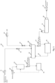
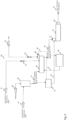
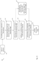
- Fig. 1 is a schematic block diagram of a system 10 for biomass treatment according to an embodiment of the present invention.
- the lignocellulosic biomass 24 may be treated in different processes, such as a soaking process, before feeding the biomass material to the storage vessel, bin or silo 11.
- the biomass material may be, for example, wood chips of softwood or hardwood, sawdust, grasses, straw, bagasse, kenaf, or other forms of agricultural waste or a combination thereof.
- the lignocellulosic biomass 24, for example, wet biomass may have a moisture content in the range of 5 - 80 %, in embodiments the DM (dry matter/dry material) is about 40-45%, and may have a temperature in a range of about 20 - 40°C.
- the biomass material is thereafter fed further to a first de-watering stage 12, for example a least one feed screw 12, e.g. a plug screw feeder.
- a first de-watering stage 12 for example a least one feed screw 12, e.g. a plug screw feeder.
- the biomass material has about 45-70% DM, or preferably about 50-60%, after the de-watering stage 12.
- the filtrate from the de-watering stage 12 is led to a water treatment stage 36, which in some embodiments may include, for example, a collector unit or filtrate tank 16 and a filtrate feeding arrangement 17 arranged to feed filtrate from the filtrate tank 16 to a reactor stage 15, see e.g. Fig. 2 .
- the water treatment stage may also be a water-purifying unit, which can be, for example, a biological purifying unit or a chemical purifying unit, or a unit for changing pH of the water by adding an acid or a base.
- the collector unit or filtrate tank include a water-purifying unit, which can be, for example, a biological purifying unit or a chemical purifying unit, or a unit for changing pH of the water by adding an acid or a base.
- the treated liquid e.g. the purified water
- the treated liquid may be circulated into the process at different stages, as shown in Fig. 1 . Further, the treated liquid can be used in the process as described below with reference to, for example, Fig. 2 - 9 .
- a screening stage may be arranged up-stream the water treatment stage 36 in order to collect any solids that has passed through the de-watering screens together with the filtrate. The solids may then be re-circulated back into the raw material flow, for example, to the storage vessel 11.
- the de-watered biomass material is fed further to an addition stage 13 where chemicals, such as e.g. acidifying chemicals 23, is added via an acid spraying system 26 and/or steam 21, e.g. high pressure steam at a pressure of about 650 - 4000 kPa or low-pressure steam at a pressure of about 90 - 1200 kPa, is added via a valve 20.
- the addition stage may comprise an impregnator, a soaking unit or a mixer screw, or a PREX-impregnation system (a Valmet product).
- a DM may be about 25 - 45% or, preferably, about 30 - 35% after the addition stage 13.
- a second de-watering stage 14 may be provided down-stream the addition stage 13 and up-stream the reactor stage 15.
- the reactor stage 15 and the addition stage 13 may be operatively coupled to the second de-watering stage 14.
- the biomass material has preferably about 45-70% DM, or preferably about 50-60%, after the second de-watering stage 14.
- the filtrate may be led to a filtrate tank 18 for use in the process.
- a screening stage may be arranged up-stream the filtrate tank 18 in order to collect any solids that has passed through the de-watering screens together with the filtrate, as described below, for example, in connection with Fig. 6 .
- the collected filtrate may be fed back into the loop in the addition stage 13 via a re-circulation arrangement 19.
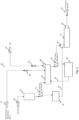
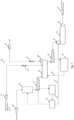
- Fig. 2 is a schematic block diagram of a system 20 for biomass treatment according to an embodiment of the present invention.
- the lignocellulosic biomass 24 may be treated in different processes, such as a soaking process, before feeding the biomass material to the storage vessel, bin or silo 11.
- the biomass material may be, for example, wood chips of softwood or hardwood, sawdust, grasses, straw, bagasse, kenaf, or other forms of agricultural waste or a combination thereof.
- the lignocellulosic biomass 24, for example, wet biomass may have a moisture content in the range of 5 - 80 %, in embodiments the DM (dry matter/dry material) is about 40-45%, and may have a temperature in a range of about 20 - 40°C.
- the biomass material is thereafter fed further to a first de-watering stage 12, for example a least one feed screw 12, e.g. a plug screw feeder.
- a first de-watering stage 12 for example a least one feed screw 12, e.g. a plug screw feeder.
- the biomass material has about 45-70% DM, or preferably about 50-60%, after the de-watering stage 12.
- the filtrate from the de-watering stage 12 is led to a collector unit or filtrate tank 16 for use in the process.
- a screening stage may be arranged up-stream the filtrate tank 16 in order to collect any solids that has passed through the de-watering screens together with the filtrate. The solids may then be recirculated back into the raw material flow, for example, to the storage vessel 11.
- the de-watered biomass material is fed further to an addition stage 13 where chemicals, such as e.g. acidifying chemicals 23, is added via an acid spraying system 26 and/or steam 21, e.g. high pressure steam at a pressure of about 650 - 4000 kPa or low-pressure steam at a pressure of about 90 - 1200 kPa, is added via a valve 20.
- the addition stage may comprise an impregnator, a soaking unit or a mixer screw or a PREX-impregnation system (a Valmet product).
- a DM may be about 25 - 45% or, preferably, about 30 - 35% after the addition stage 13.
- a filtrate feeding arrangement 17 is arranged to feed filtrate from the filtrate tank 16 to a reactor stage 15, e.g. a pre-hydrolysis reactor 15, to e.g. an inlet 27 of the reactor stage 15.
- a second de-watering stage 14 may be provided down-stream the addition stage 13 and up-stream the reactor stage 15.
- the reactor stage 15 and the addition stage 13 may be operatively coupled to the second de-watering stage 14.
- the biomass material has preferably about 45-70% DM, or preferably about 50-60%, after the second de-watering stage 14.
- the filtrate may be led to a filtrate tank 18 for use in the process.
- a screening stage may be arranged up-stream the filtrate tank 18 in order to collect any solids that has passed through the de-watering screens together with the filtrate, as described below in connection with Fig. 5 .
- the collected filtrate may be fed back into the loop in the addition stage 13 via a re-circulation arrangement 19.
- the system 30 includes a storage unit, e.g. a silo, 11 to which the lignocellulosic biomass 24, for example, wet biomass having a moisture content in the range of 5 - 80 %, in embodiments the DM (dry matter/dry material) is about 40-45%, and a temperature in a range of about 20 - 40°C is provided.
- a storage unit e.g. a silo, 11 to which the lignocellulosic biomass 24, for example, wet biomass having a moisture content in the range of 5 - 80 %, in embodiments the DM (dry matter/dry material) is about 40-45%, and a temperature in a range of about 20 - 40°C is provided.
- the biomass material is fed further to a first de-watering stage 12, for example a least one feed screw 12, e.g. a plug screw feeder.
- the biomass material has about 45-70% DM, or preferably about 50-60%, after the de-watering stage 12.
- the filtrate from the de-watering stage 12 is led to a collector unit or filtrate tank 16 for use in the process.
- a screening stage may be arranged up-stream the filtrate tank 16 in order to collect any solids that has passed through the de-watering screens together with the filtrate. The solids may then be recirculated back into the raw material flow, for example, to the storage vessel 11.
- the de-watered biomass material is fed further to an addition stage 13 where chemicals, such as e.g. acidifying chemicals 23, is added via an acid spraying system 26 and/or steam 21, e.g. high pressure steam at a pressure of about 650 - 4000 kPa or low-pressure steam at a pressure of about 90 - 1200 kPa, is added via a valve 20.
- the addition stage may comprise an impregnator, a soaking unit or a mixer screw or a PREX-impregnation system (a Valmet product).
- a DM may be about 25 - 45% or, preferably, about 30 - 35% after the addition stage 13.
- a filtrate feeding arrangement 17 is arranged to feed filtrate from the filtrate tank 16 to a reactor stage 15, e.g. a pre-hydrolysis reactor 15.
- the filtrate is fed to a discharge part 28 of the reactor stage 15, e.g. to clean a discharge screw is there one arranged in the reactor 15, or to clean the discharge part 28 and/or to dilute the discharged treated biomass.
- a second de-watering stage 14 may be provided down-stream the addition stage 13 and up-stream the reactor stage 15.
- the reactor stage 15 and the addition stage 13 may be operatively coupled to the second de-watering stage 14.
- the biomass material has about 45-70% DM, or preferably about 50-60%, after the second de-watering stage 14.
- the filtrate may be led to a filtrate tank 18 for use in the process.
- a screening stage 37 shown in Fig. 6 , may be arranged up-stream the filtrate tank 18 in order to collect any solids that has passed through the de-watering screens together with the filtrate, as described below in connection with Fig. 6 .
- the collected filtrate may be fed back into the loop in the addition stage 13 via a re-circulation arrangement 19.
- the system 40 includes a storage unit, e.g. a silo, 11 to which the lignocellulosic biomass 24, for example, wet biomass having a moisture content in the range of 5 - 80 %, in embodiments the DM (dry matter/dry material) is about 40-45%, and a temperature in a range of about 20 - 40°C is provided.
- a storage unit e.g. a silo, 11 to which the lignocellulosic biomass 24, for example, wet biomass having a moisture content in the range of 5 - 80 %, in embodiments the DM (dry matter/dry material) is about 40-45%, and a temperature in a range of about 20 - 40°C is provided.
- the biomass material is thereafter fed further to a first de-watering stage 12, for example a least one feed screw 12, e.g. a plug screw feeder.
- the biomass material has about 45-70% DM, or preferably about 50-60%, after the de-watering stage 12.
- the filtrate from the de-watering stage 12 is led to a collector unit or filtrate tank 16 for use in the process.
- a screening stage may be arranged up-stream the filtrate tank 16 in order to collect any solids that has passed through the de-watering screens together with the filtrate. The solids may then be recirculated back into the raw material flow, for example, to the storage vessel 11.
- the de-watered biomass material is fed further to an addition stage 13 where chemicals, such as e.g. acidifying chemicals 23, is added via an acid spraying system 26 and/or steam 21, e.g. high pressure steam at a pressure of about 650 - 4000 kPa or low-pressure steam at a pressure of about 90 - 1200 kPa, is added via a valve 20.
- the addition stage may comprise an impregnator, a soaking unit or a mixer screw, or a PREX-impregnation system (a Valmet product).
- a DM may be about 25 - 45% or, preferably, about 30 - 35% after the addition stage 13.
- a filtrate feeding arrangement 17 is arranged to feed filtrate from the filtrate tank 16 to a reactor stage 15, e.g. a pre-hydrolysis reactor 15.
- the filtrate is fed to cleaning nozzles 29 of the reactor stage to clean a reactor screw 34.
- a second de-watering stage 14 may be provided down-stream the addition stage 13 and up-stream the reactor stage 15.
- the reactor stage 15 and the addition stage 13 may be operatively coupled to the second de-watering stage 14.
- the biomass material has about 45-70% DM, or preferably about 50-60%, after the second de-watering stage 14.
- the filtrate may be led to a filtrate tank 18 for use in the process.
- a screening stage may be arranged up-stream the filtrate tank 18 in order to collect any solids that has passed through the de-watering screens together with the filtrate, as described below in connection with Fig. 5 .
- the collected filtrate may be fed back into the loop in the addition stage 13 via a re-circulation arrangement 19.
- the system 50 includes a storage unit, e.g. a silo, 11 to which the lignocellulosic biomass 24, for example, wet biomass having a moisture content in the range of 5 - 80 %, in embodiments the DM (dry matter/dry material) is about 40-45%, and a temperature in a range of about 20 - 40°C is provided.
- the biomass material is thereafter fed further to a first de-watering stage 12, for example a least one feed screw 12, e.g. a plug screw feeder.
- the biomass material has about 45-70% DM, or preferably about 50-60%, after the de-watering stage 12.
- the filtrate from the de-watering stage 12 is led to a collector unit or filtrate tank 16 for use in the process.
- a screening stage may be arranged up-stream the filtrate tank 16 in order to collect any solids that has passed through the de-watering screens together with the filtrate. The solids may then be recirculated back into the raw material flow, for example, to the storage vessel 11.
- the de-watered biomass material is fed further to an addition stage 13 where chemicals, such as e.g. acidifying chemicals 23, is added via an acid spraying system 26 and/or steam 21, e.g. high pressure steam at a pressure of about 650 - 4000 kPa or low-pressure steam at a pressure of about 90 - 1200 kPa, is added via a valve 20.
- the addition stage may comprise an impregnator, a soaking unit or a mixer screw, or a PREX-impregnation system (a Valmet product).
- a DM may be about 25 - 45% or, preferably, about 30 - 35% after the addition stage 13.
- a filtrate feeding arrangement 17 is arranged to feed filtrate from the filtrate tank 16 to a reactor stage 15, e.g. a pre-hydrolysis reactor 15.
- the filtrate is fed to the reactor stage, e.g. an inlet 27 of the reactor stage 15, e.g. to be sprayed over the incoming biomass material, and via a second filtrate feeding arrangement 35 to the acid spraying system 26 if more liquid is need to maintain a balance in the added liquid.
- a second de-watering stage 14 may be provided down-stream the addition stage 13 and up-stream the reactor stage 15.
- the reactor stage 15 and the addition stage 13 may be operatively coupled to the second de-watering stage 14.
- the biomass material has about 45-70% DM, or preferably about 50-60%, after the second de-watering stage 14.
- the filtrate may be led to a filtrate tank 18 for use in the process.
- a screening stage may be arranged up-stream the filtrate tank 18 in order to collect any solids that has passed through the de-watering screens together with the filtrate, as described below in connection with Fig. 6 .
- the collected filtrate may be fed back into the loop in the addition stage 13 via a re-circulation arrangement 19.
- the system 60 includes a storage unit, e.g. a silo, 11 to which the lignocellulosic biomass 24, for example, wet biomass having a moisture content in the range of 5 - 80 %, in embodiments the DM (dry matter/dry material) is about 40-45%, and a temperature in a range of about 20 - 40°C is provided.
- the biomass material is thereafter fed further to a first de-watering stage 12, for example a least one feed screw 12, e.g. a plug screw feeder.
- the biomass material has about 45-70% DM, or preferably about 50-60%, after the de-watering stage 12.
- the filtrate from the de-watering stage 12 is led to a collector unit or filtrate tank 16 for use in the process.
- a screening stage may be arranged up-stream the filtrate tank 16 in order to collect any solids that has passed through the de-watering screens together with the filtrate. The solids may then be recirculated back into the raw material flow, for example, to the storage vessel 11.
- the de-watered biomass material is fed further to an addition stage 13 where chemicals, such as e.g. acidifying chemicals 23, is added via an acid spraying system 26 and/or steam 21, e.g. high pressure steam at a pressure of about 650 - 4000 kPa or low-pressure steam at a pressure of about 90 - 1200 kPa, is added via a valve 20.
- the addition stage may comprise an impregnator, a soaking unit or a mixer screw.
- a DM may be about 25 - 45% or, preferably, about 30 - 35% after the addition stage 13.
- a recovery and refining stage or screening stage 33 is coupled to the filtrate tank 16 to screen the filtrate to for example remove any solids present in the filtrate.
- the solids may then be recirculated to the biomass material 24 provided into the process.
- the refined filtrate may be fed to the reactor stage 15 via the filtrate feeding arrangement 17, for example, as described with reference to Fig. 1 - 4 .
- a second de-watering stage 14 may be provided down-stream the addition stage 13 and up-stream the reactor stage 15.
- the reactor stage 15 and the addition stage 13 may be operatively coupled to the second de-watering stage 14.
- the biomass material has about 45-70% DM, or preferably about 50-60%, after the second de-watering stage 14.
- the filtrate may be led to a filtrate tank 18 for use in the process.
- a recovery and refining or screening stage 37 is arranged up-stream the filtrate tank 18 in order to collect any solids that has passed through the de-watering screens together with the filtrate. Thereafter, the collected filtrate may be fed back into the loop in the addition stage 13 via a re-circulation arrangement 19.
- the system 70 includes a storage unit, e.g. a silo, 11 to which the lignocellulosic biomass 24, for example, wet biomass, e.g. wood chips, having a moisture content in the range of 5 - 80 %, in embodiments the DM (dry matter/dry material) is about 40-45%, and a temperature in a range of about 20 - 40°C is provided.
- the biomass material is thereafter fed further to a first de-watering stage 12, for example a least one feed screw 12, e.g. a plug screw feeder.
- the biomass material has about 45-70% DM, or preferably about 50-60%, after the de-watering stage 12.
- the filtrate from the de-watering stage 12 is led to a collector unit or filtrate tank 16 for use in the process.
- a screening stage 33 is arranged up-stream the filtrate tank 16 in order to collect any solids that has passed through the de-watering screens together with the filtrate. The solids may then be recirculated back into the raw material flow, for example, to the storage vessel 11.
- the de-watered biomass material is fed further to an addition stage 13 where chemicals, such as e.g. acidifying chemicals 23, is added via an acid spraying system 26 and/or steam 21, e.g. high pressure steam at a pressure of about 650 - 4000 kPa or low-pressure steam at a pressure of about 90 - 1200 kPa, is added via a valve 20.
- the addition stage may comprise an impregnator, a soaking unit or a mixer screw.
- a DM may be about 25 - 45% or, preferably, about 30 - 35% after the addition stage 13.
- a recovery and refining stage or screening stage 33 is coupled to the filtrate tank 16 to screen the filtrate to for example remove any solids present in the filtrate.
- the solids may then be recirculated to the biomass material 24 provided into the process.
- the refined filtrate is be fed to the reactor stage 15 via the filtrate feeding arrangement 17, for example, as described with reference to Fig. 2-5 .
- a main part of the refined filtrate is fed to the reactor stage 15 and a fraction of the filtrate, for example, 1 - 5% is fed upstream in the process, for example, to the storage vessel or silo 11 as shown in Fig. 7 and/or to a raw material washer 38, or biomass washer, or wood chip washer as in the system 80 shown in Fig. 8 .
- a second de-watering stage 14 may be provided down-stream the addition stage 13 and up-stream the reactor stage 15.
- the reactor stage 15 and the addition stage 13 may be operatively coupled to the second de-watering stage 14.
- the biomass material has about 45-70% DM, or preferably about 50-60%, after the second de-watering stage 14.
- the filtrate may be led to a filtrate tank 18 for use in the process.
- a recovery and refining or screening stage 33 is arranged up-stream the filtrate tank 18 in order to collect any solids that has passed through the de-watering screens together with the filtrate. Thereafter, the collected filtrate may be fed back into the loop in the addition stage 13 via a re-circulation arrangement 19.
- the system 90 includes a storage unit, e.g. a silo, 11 to which the lignocellulosic biomass 24, for example, wet biomass, e.g. wood chips, having a moisture content in the range of 5 - 80 %, in embodiments the DM (dry matter/dry material) is about 40-45%, and a temperature in a range of about 20 - 40°C is provided.
- the biomass material is thereafter fed further to a first de-watering stage 12, for example a least one feed screw 12, e.g. a plug screw feeder.
- the biomass material has about 45-70% DM, or preferably about 50-60%, after the de-watering stage 12.
- the filtrate from the de-watering stage 12 is led to a collector unit or filtrate tank 16 for use in the process.
- a screening stage 33 is arranged up-stream the filtrate tank 16 in order to collect any solids that has passed through the de-watering screens together with the filtrate. The solids may then be recirculated back into the raw material flow, for example, to the storage vessel 11.
- the de-watered biomass material is fed further to an addition stage 13 where chemicals, such as e.g. acidifying chemicals 23, is added via an acid spraying system 26 and/or steam 21, e.g. high pressure steam at a pressure of about 650 - 4000 kPa or low-pressure steam at a pressure of about 90 - 1200 kPa, is added via a valve 20.
- the addition stage may comprise an impregnator, a soaking unit or a mixer screw.
- a DM may be about 25 - 45% or, preferably, about 30 - 35% after the addition stage 13.
- a recovery and refining stage or screening stage 33 is coupled to the filtrate tank 16 to screen the filtrate to for example remove any solids present in the filtrate.
- the solids may then be recirculated to the biomass material 24 provided into the process.
- the refined filtrate is be fed to the reactor stage 15 via the filtrate feeding arrangement 17, for example, as described with reference to Fig. 2-5 .
- the filtrate may be fed to a discharge part 28 of the reactor stage 15, e.g.
- to clean a discharge screw is there one arranged in the reactor 15, or to clean the discharge part 28 and/or to dilute the discharged treated biomass, or to cleaning nozzles 29 arranged in the reactor vessel to clean a reactor screw 34, or to an inlet 27 of the reactor stage 15, e.g. to be sprayed over the incoming biomass material, and/or via a second filtrate feeding arrangement 35 to the acid spraying system 26 if more liquid is need to maintain a balance in the added liquid.
- a main part of the refined filtrate is fed to the reactor stage 15 and a fraction of the filtrate, for example, 1 - 5% is fed upstream in the process, for example, to the storage vessel or silo 11 and/or to a raw material washer 38, or biomass washer, or wood chip washer.
- a second de-watering stage 14 may be provided down-stream the addition stage 13 and up-stream the reactor stage 15.
- the reactor stage 15 and the addition stage 13 may be operatively coupled to the second de-watering stage 14.
- the biomass material has about 45-70% DM, or preferably about 50-60%, after the second de-watering stage 14.
- the filtrate may be led to a filtrate tank 18 for use in the process.
- a recovery and refining or screening stage 33 is arranged up-stream the filtrate tank 18 in order to collect any solids that has passed through the de-watering screens together with the filtrate. Thereafter, the collected filtrate may be fed back into the loop in the addition stage 13 via a re-circulation arrangement 19.
- the method relates to treatment and feeding of lignocellulosic biomass which is treated at elevated temperature and pressure with steam or mixtures of steam and acidifying solutions.
- the lignocellulosic biomass material such as wood chips, may be treated in different processes, such as a soaking process, before feeding the biomass material to a storage vessel, bin or silo 11.
- the biomass material 24 provided into the process may be, for example, wood chips of softwood or hardwood, sawdust, grasses, straw, bagasse, kenaf, or other forms of agricultural waste or a combination thereof.
- the lignocellulosic biomass may, for example, be wet biomass may have a moisture content in the range of 5 - 80 %, in embodiments the DM (dry matter/dry material) is about 40-45%, and may have a temperature in a range of about 20 - 40°C.
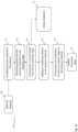
- the lignocellulosic biomass material 24 is fed, at step 111 to a silo 11. Thereafter, at step 112, liquid is removed from the biomass in a first de-watering stage 12, for example a least one feed screw 12, e.g. a plug screw feeder.
- a first de-watering stage 12 for example a least one feed screw 12, e.g. a plug screw feeder.
- the biomass material has about 45-70% DM, or preferably about 50-60%, after the de-watering stage 12.
- the filtrate from the de-watering stage 12 is collected and provided to water treatment 117.
- an addition step is performed in an addition stage 13 where chemicals, such as e.g. acidifying chemicals 23, is added via an acid spraying system 26 and/or steam 21, e.g. high pressure steam at a pressure of about 650 - 4000 kPa or low-pressure steam at a pressure of about 90 - 1200 kPa, is added via a valve 20.
- the addition stage may comprise an impregnator, a soaking unit or a mixer screw.
- a DM may be about 25 - 45% or, preferably, about 30 - 35% after the addition stage 13.
- a treatment process in a reactor stage 15 is performed, e.g. a pre-hydrolysis process, on the biomass material.
- the treated biomass material may be fed to further processing steps.
- the lignocellulosic biomass material 24 is fed, at step 211 to a silo 11. Thereafter, at step 212, liquid is removed from the biomass in a first de-watering stage 12, for example a least one feed screw 12, e.g. a plug screw feeder.
- a first de-watering stage 12 for example a least one feed screw 12, e.g. a plug screw feeder.
- the biomass material has about 45-70% DM, or preferably about 50-60%, after the de-watering stage 12.
- the filtrate from the de-watering stage 12 is collected in a collector unit or filtrate tank 16 for use in the process.
- an addition step is performed in an addition stage 13 where chemicals, such as e.g. acidifying chemicals 23, is added via an acid spraying system 26 and/or steam 21, e.g. high pressure steam at a pressure of about 650 - 4000 kPa or low-pressure steam at a pressure of about 90 - 1200 kPa, is added via a valve 20.
- the addition stage may comprise an impregnator, a soaking unit or a mixer screw.
- a DM may be about 25 - 45% or, preferably, about 30 - 35% after the addition stage 13.
- a treatment process in a reactor stage 15 is performed, e.g. a pre-hydrolysis process, on the biomass material.
- the filtrate collected from the first de-watering stage 12 is re-cycled or fed to the reactor stage 15 using a filtrate feeding arrangement 17 arranged to feed filtrate from the filtrate tank 16 to the reactor stage 15, e.g. a pre-hydrolysis reactor 15.
- the filtrate may be fed to a discharge part 28 of the reactor stage 15, e.g. to clean a discharge screw is there one arranged in the reactor 15, or to clean the discharge part 28 and/or to dilute the discharged treated biomass, or to cleaning nozzles 29 arranged in the reactor vessel to clean a reactor screw 34, or to an inlet 27 of the reactor stage 15, e.g. to be sprayed over the incoming biomass material, and/or via a second filtrate feeding arrangement 35 to the acid spraying system 26 if more liquid is need to maintain a balance in the added liquid.
- the treated biomass material may be fed to further processing steps.
- the method relates to treatment and feeding of lignocellulosic biomass which is treated at elevated temperature and pressure with steam or mixtures of steam and acidifying solutions.
- the lignocellulosic biomass material may be treated in different processes, such as a soaking process, before feeding the biomass material to a storage vessel, bin or silo 11.
- the biomass material 24 provided into the process may be, for example, wood chips of softwood or hardwood, sawdust, grasses, straw, bagasse, kenaf, or other forms of agricultural waste or a combination thereof.
- the lignocellulosic biomass may, for example, be wet biomass may have a moisture content in the range of 5 - 80 %, in embodiments the DM (dry matter/dry material) is about 40-45%, and may have a temperature in a range of about 20 - 40°C.
- the lignocellulosic biomass material 24 is fed, at step 311 to a silo 11. Thereafter, at step 312, liquid is removed from the biomass in a first de-watering stage 12, for example a least one feed screw 12, e.g. a plug screw feeder.
- a first de-watering stage 12 for example a least one feed screw 12, e.g. a plug screw feeder.
- the biomass material has about 45-70% DM, or preferably about 50-60%, after the de-watering stage 12.
- the filtrate from the de-watering stage 12 is collected in a collector unit or filtrate tank 16 for use in the process.
- an addition step is performed in an addition stage 13 where chemicals, such as e.g. acidifying chemicals 23, is added via an acid spraying system 26 and/or steam 21, e.g. high pressure steam at a pressure of about 650 - 4000 kPa or low-pressure steam at a pressure of about 90 - 1200 kPa, is added via a valve 20.
- the addition stage may comprise an impregnator, a soaking unit or a mixer screw.
- a DM may be about 25 - 45% or, preferably, about 30 - 35% after the addition stage 13.
- a second de-watering step is performed down-stream the addition stage 13.
- the biomass material has about 45-70% DM, or preferably about 50-60%, after the second de-watering stage 14.
- the filtrate may be led to a filtrate tank 18 for use in the process.
- a screening stage may be arranged up-stream the filtrate tank 18 in order to collect any solids that has passed through the de-watering screens together with the filtrate, as described below in connection with Fig. 5 .
- the collected filtrate is recycled into the process loop in the addition stage 13 via a re-circulation arrangement 19.
- a treatment process in a reactor stage 15 is performed, e.g. a pre-hydrolysis process, on the biomass material.
- the filtrate collected from the first de-watering stage 12 is re-cycled or fed to the reactor stage 15 using a filtrate feeding arrangement 17 arranged to feed filtrate from the filtrate tank 16 to the reactor stage 15, e.g. a pre-hydrolysis reactor 15.
- the filtrate may be fed to a discharge part 28 of the reactor stage 15, e.g. to clean a discharge screw is there one arranged in the reactor 15, or to clean the discharge part 28 and/or to dilute the discharged treated biomass, or to cleaning nozzles 29 arranged in the reactor vessel to clean a reactor screw 34, or to an inlet 27 of the reactor stage 15, e.g. to be sprayed over the incoming biomass material, and/or via a second filtrate feeding arrangement 35 to the acid spraying system 26 if more liquid is need to maintain a balance in the added liquid.
- the treated biomass material may be fed to further processing steps.
Landscapes
- Chemical & Material Sciences (AREA)
- Organic Chemistry (AREA)
- Life Sciences & Earth Sciences (AREA)
- Wood Science & Technology (AREA)
- Engineering & Computer Science (AREA)
- Zoology (AREA)
- Health & Medical Sciences (AREA)
- Bioinformatics & Cheminformatics (AREA)
- Genetics & Genomics (AREA)
- Microbiology (AREA)
- Biochemistry (AREA)
- General Engineering & Computer Science (AREA)
- General Health & Medical Sciences (AREA)
- Biotechnology (AREA)
- General Chemical & Material Sciences (AREA)
- Chemical Kinetics & Catalysis (AREA)
- Molecular Biology (AREA)
- Biomedical Technology (AREA)
- Sustainable Development (AREA)
- Processing Of Solid Wastes (AREA)
- Solid Fuels And Fuel-Associated Substances (AREA)
Description
- The present invention relates to feeding arrangements and systems for hydrolysis and pre-hydrolysis processes for production of biofuels such as ethanol using, e.g. biodegradable waste, or lignocellulosic biomass material including wood waste, e.g. saw dust, or plant material including annual plants.
- The oil resources in the world are diminishing at the same time as the demand for energy increases. This increasing demand for energy cannot be met by fossil sources since the global emissions of greenhouse gases, such as CO2, needs to be reduced. This is particularly important within the transportation sector and the development of efficient methods for producing biofuels, both in terms of usage of resources and economy, are therefore critical. Ethanol has been an alternative for gasoline for many years but has now become an increasingly important biofuel as source for motor fuel and fuel additive. Ethanol can be produced from biodegradable waste, e.g. food waste, grain-based feed stocks, e.g. corn, wheat, or soybeans, from sugar, e.g. from sugar beets, from biomass, lignocellulosic biomass material such as wood, or plant material including annual plants.
- In current processes for producing biofuel, such as ethanol, the raw material is fed into a pre-hydrolysis reactor. The raw material can also be pre-steamed or pre-impregnated before being fed into the pre-hydrolysis reactor or other chemical reactor. Usually an acidifying chemical, e.g. H2SO4, is added in a process stage up-stream the reactor, for example in an impregnation stage, in a soaking stage or in a mixer screw by spraying. The acidified material is then fed into the reactor using a feeding device, e.g. a plug screw feeder, and a major part of the liquid in the material is removed as filtrate. The filtrate is then recirculated in the process and used to impregnate or to spray raw material fed into the process together with acidifying chemicals. When using raw material with a high moisture content, the amount of filtrate that is removed in the plug screw is higher than the amount of filtrate that is needed to acidify the raw material. Therefore, the remaining surplus filtrate is fed into the pre-hydrolysis reactor, or other chemical reactor in the process. However, this surplus filtrate contains acidifying chemicals which results in inter alia corrosion in the reactor and negative effects in the process itself within the reactor if filtrate containing acidifying chemical is sprayed on the surface of the raw material. For example, it may result in a faster reaction at the surface of the material. In addition, it is also difficult to handle the high amount of surplus filtrate containing acidifying chemicals in a wastewater plant.
- Dewatering the biomass and recycling the obtained filtrate back in the process has been described in e.g. patent documents
US 2011/281298 , -
WO 2017/088061 orUS2009/0061495 . InUS 2011/281298 , the filtrates are obtained from dewatering the biomass downstream of the pre-hydrolysis. InWO 2017/088061 , the collected liquids obtained during treatment of biomass are recycled for slurrying or soaking the biomass and not for the pre-hydrolysis of biomass. InUS2009/0061495 , the collected liquids after washing the biomass are sent to the hydrolysis/fermentation process but the process lacks a filtration tank which receives and collects the liquid from the dewatering stage. Thus, there is a need for improved processes and systems for treating biomass in pre-hydrolysis systems for biofuel production. - An object of the present invention is to provide improved processes and systems for treating biomass in pre-hydrolysis systems for biofuel production.
- Another object of the present invention is to provide a more efficient handling of liquid and water in processes and systems for treating biomass in pre-hydrolysis systems for biofuel production.
- A further object of the present invention is to provide processes and systems for treating biomass in pre-hydrolysis systems for biofuel production where the wear such as corrosion can be significantly reduced in essential parts of the system such as the pre-hydrolysis reactor.
- Yet another object of the system is to provide processes and systems for treating biomass in pre-hydrolysis systems for biofuel production that are capable of using raw material with a high degree of moisture without affecting the balance of the system and with an efficient water usage.
- These and other objects are met by the present invention as defined by the claims and embodiments described herein.
- According to an aspect of the present invention, there is provided a treatment process system for biomass material comprising a first dewatering stage arranged to receive biomass material, to remove liquid from the biomass material, and to feed the biomass material forward in the process. Further, the system includes a first filtrate tank operatively coupled to the first dewatering stage and is arranged to collect the liquid removed in the first dewatering stage. An addition stage is located downstream the dewatering stage and is operatively coupled to the first dewatering stage. The addition stage is arranged to receive the de-watered biomass material, wherein the addition stage includes inlets for adding acid containing solution into the addition stage. A reactor stage arranged to receive the biomass material treated in the addition stage and to perform a pre-hydrolysis process to the biomass material. A filtrate feeding arrangement is operatively coupled to the first filtrate tank and is arranged to feed liquid from the filtrate tank to the reactor stage. Thus, the liquid or water removed from the biomass in the first dewatering stage is re-cycled in the process downstream the stage where acid is added. As understood from the present application, the liquid or water can be passed through a filtering or screening stage before being fed to the reactor, where it can be fed to a discharge part including a discharging screw, to cleaning nozzles arranged into the reactor or an inlet part of the reactor. The filtrate may also, or instead, be fed upstream in the process to the dewatering stage, the silo, or a washing stage upstream the silo.
- According to another aspect of the present invention, there is provided a method or process for treating biomass material comprising the steps of: removing liquid from the biomass material in a first de-watering stage; collecting the removed liquid from the first de-watering stage; adding an acid containing solution to the biomass material; performing a pre-hydrolysis process in a reactor stage on the biomass material; and recycling the collected liquid from first de-watering stage to the reactor stage.
- The present invention is based on the insight that by performing a dewatering process up-stream the addition stage where chemicals, such as e.g. sulfuric acid (H2SO4), are added to the biomass material, surplus filtrate of the biomass material can be collected and cleaned or treated in a water treatment stage. By arranged a dewatering stage upstream the stage where chemical are added, the water treatment is significantly simplified since equipment for cleaning or removing acids or chemicals from the liquid or water is not needed. According to aspect of the invention, the surplus filtrate that is removed in the dewatering stage is re-cycled into the process downstream the acid-addition stage, for example, in the reactor stage, which hence is possible without any special concerns required when the filtrate contains acidifying chemicals.
- For example, the filtrate can be collected and fed directly into the reactor stage or it can be sent to waste water treatment without any pre-treatment stage since it does not contain any acidifying chemicals.
- In other words, the present invention is based on the idea of adding a first de-watering step or stage before the addition of chemical, such as acidifying liquids, to thereby enabling recovery of filtrate without any added chemicals. This makes it possible to flexible use of the surplus filtrate in the process, for example, in the reactor without any risk for corrosion inside the reactor vessel. Another advantage is that the amount of process water used in the system can be reduced since the recycling of filtrate is significantly improved by the present invention.
- In embodiments of the present invention, the he filtrate feeding arrangement is arranged to feed liquid from the filtrate tank to cleaning nozzles of the reactor stage.
- In other embodiments of the present invention, the filtrate feeding arrangement is arranged to feed liquid from the filtrate tank to a discharge unit of the reactor stage.
- According to further embodiments, the filtrate feeding arrangement is arranged to feed liquid from the filtrate tank to an inlet part of the reactor stage.
- In yet other embodiments of the present invention, the addition stage comprises an impregnator, or a soaking unit, or a mixer screw, or a PREX impregnation system (a Valmet product).
- In embodiments, a second dewatering stage is arranged downstream the addition stage and operatively coupled to the addition stage. The second dewatering stage is arranged to receive biomass material, to remove liquid from the biomass material, and to feed the biomass material forward in the process.
- According to embodiments of the present invention, a second filtrate tank is arranged to collect removed liquid from the second dewatering stage and a re-circulation arrangement is arranged to feed liquid from the second filtrate tank to the addition stage.
- In embodiments of the present invention, the inlets for adding acid containing solution are controlled to add acid containing solution to the biomass material such that an acid content is a range of 0 - 10% weight/weight of the biomass material, or in a range of 0.001 - 10% weight/weight of the biomass material. In embodiments, sulfuric acid (H2SO4) is added to the biomass material.
- In further embodiments of the present invention, the first and second de-watering stages and addition stage are arranged to operate at atmospheric pressure.
- In embodiments of the present invention, the reactor stage is arranged to operate at a pressure in a range of 5 - 25 bar and/or a temperature in a range of 150°C - 230°C.
- According to embodiments of the present invention, a pre-steaming stage is arranged up-stream said first de-watering stage, said pre-steaming stage being arranged to perform a pre-steaming process on said biomass material.
- In embodiments of the present invention, a recovery and refining stage is coupled to the first filtrate tank and is arranged to perform a refining process on the filtrate to recover selected compounds from the filtrate.
- In other embodiments of the present invention, a recovery and refining stage is coupled to the first filtrate tank and is arranged to perform a refining process on the filtrate to recover selected compounds from the filtrate.
- In the context of the present invention, the term "plug screw feeder" relates to a feeder comprising a screw or similar rotating means and which is capable of feeding or transporting lignocellulosic material through the feeder at increased or maintained density of the material and that creates an essentially gas- and fluid-tight plug of the lignocellulosic material towards the end of the feeder. For example, according to an embodiment of such a plug screw feeder, a cross-sectional area of the circular housing of the feeder and the screw diameter decreases in the feeding direction thereby so as to create a decreasing space between the screw and the housing and thus resulting in an essentially gas- and fluid-tight plug of the lignocellulosic material towards the end of the feeder. According to another embodiment of a plug screw feeder, the cross-sectional area of the circular housing of the feeder is constant while and the screw diameter and screw axis increases in the feeding direction thereby creating a decreasing space between the screw and the housing and thus resulting in an essentially gas- and fluid-tight plug of the lignocellulosic material towards the end of the feeder. As the skilled person realizes, there are other embodiments of feeders that achieves this purpose and thus are included within the definition of the term "plug screw feeder".
- Further, a force-feeding screw that may be used in the present invention is described in, for example,
WO 2013126007 . - Further advantageous embodiments of the device according to the present invention and further advantages with the present invention emerge from the detailed description of embodiments.
- The present invention will now be described, for exemplary purposes, in more detail by way of embodiments and with reference to the enclosed drawings, in which:
-
Fig. 1 is a schematic view of an embodiment of the system according to the present invention; -
Fig. 2 is a schematic view of another embodiment of the system according to the present invention; -
Fig. 3 is a schematic view of yet another further embodiment of the system according to the present invention; -
Fig. 4 is a schematic view of an embodiment of the system according to the present invention; -
Fig. 5 is a schematic view of a further embodiment of the system according to the present invention; -
Fig. 6 is a schematic view of yet another embodiment of the system according to the present invention; -
Fig. 7 is a schematic view of a further embodiment of the system according to the present invention; -
Fig. 8 is a schematic view of an embodiment of the system according to the present invention; -
Fig. 9 is a schematic view of a further embodiment of the system according to the present invention; -
Fig. 10 illustrates steps of a method according to an embodiment of the present invention; -
Fig. 11 illustrates steps of a method according a further embodiment of the present invention; and -
Fig. 12 illustrates steps of a method according to an embodiment of the present invention. - In the drawings, similar or corresponding elements are denoted by the same reference numbers.
- For the purpose of this disclosure, the term longitudinal refers to the direction along which a body, part or element has its greatest extension. Further, when the term longitudinal is used in connection with the axes of screws, the longitudinal axis corresponds to the rotational axis of the screw.
- Turning first to
Fig. 1 , where a system according to an embodiment of the present invention is shown.Fig. 1 is a schematic block diagram of a system 10 for biomass treatment according to an embodiment of the present invention. Thelignocellulosic biomass 24 may be treated in different processes, such as a soaking process, before feeding the biomass material to the storage vessel, bin orsilo 11. The biomass material may be, for example, wood chips of softwood or hardwood, sawdust, grasses, straw, bagasse, kenaf, or other forms of agricultural waste or a combination thereof. - The
lignocellulosic biomass 24, for example, wet biomass may have a moisture content in the range of 5 - 80 %, in embodiments the DM (dry matter/dry material) is about 40-45%, and may have a temperature in a range of about 20 - 40°C. - The biomass material is thereafter fed further to a first
de-watering stage 12, for example a least onefeed screw 12, e.g. a plug screw feeder. In embodiments of the present invention, the biomass material has about 45-70% DM, or preferably about 50-60%, after thede-watering stage 12. - The filtrate from the
de-watering stage 12 is led to awater treatment stage 36, which in some embodiments may include, for example, a collector unit orfiltrate tank 16 and afiltrate feeding arrangement 17 arranged to feed filtrate from thefiltrate tank 16 to areactor stage 15, see e.g.Fig. 2 . The water treatment stage may also be a water-purifying unit, which can be, for example, a biological purifying unit or a chemical purifying unit, or a unit for changing pH of the water by adding an acid or a base. In some embodiments, the collector unit or filtrate tank include a water-purifying unit, which can be, for example, a biological purifying unit or a chemical purifying unit, or a unit for changing pH of the water by adding an acid or a base. - The treated liquid, e.g. the purified water, may be circulated into the process at different stages, as shown in
Fig. 1 . Further, the treated liquid can be used in the process as described below with reference to, for example,Fig. 2 - 9 . A screening stage may be arranged up-stream thewater treatment stage 36 in order to collect any solids that has passed through the de-watering screens together with the filtrate. The solids may then be re-circulated back into the raw material flow, for example, to thestorage vessel 11. - The de-watered biomass material is fed further to an
addition stage 13 where chemicals, such ase.g. acidifying chemicals 23, is added via anacid spraying system 26 and/orsteam 21, e.g. high pressure steam at a pressure of about 650 - 4000 kPa or low-pressure steam at a pressure of about 90 - 1200 kPa, is added via avalve 20. In embodiments of the present invention, the addition stage may comprise an impregnator, a soaking unit or a mixer screw, or a PREX-impregnation system (a Valmet product). A DM may be about 25 - 45% or, preferably, about 30 - 35% after theaddition stage 13. - A second
de-watering stage 14 may be provided down-stream theaddition stage 13 and up-stream thereactor stage 15. Thereactor stage 15 and theaddition stage 13 may be operatively coupled to the secondde-watering stage 14. The biomass material has preferably about 45-70% DM, or preferably about 50-60%, after the secondde-watering stage 14. The filtrate may be led to afiltrate tank 18 for use in the process. A screening stage may be arranged up-stream thefiltrate tank 18 in order to collect any solids that has passed through the de-watering screens together with the filtrate, as described below, for example, in connection withFig. 6 . The collected filtrate may be fed back into the loop in theaddition stage 13 via are-circulation arrangement 19. - Turning now to
Fig. 2 , where a system according to an embodiment of the present invention is shown.Fig. 2 is a schematic block diagram of asystem 20 for biomass treatment according to an embodiment of the present invention. Thelignocellulosic biomass 24 may be treated in different processes, such as a soaking process, before feeding the biomass material to the storage vessel, bin orsilo 11. The biomass material may be, for example, wood chips of softwood or hardwood, sawdust, grasses, straw, bagasse, kenaf, or other forms of agricultural waste or a combination thereof. - The
lignocellulosic biomass 24, for example, wet biomass may have a moisture content in the range of 5 - 80 %, in embodiments the DM (dry matter/dry material) is about 40-45%, and may have a temperature in a range of about 20 - 40°C. - The biomass material is thereafter fed further to a first
de-watering stage 12, for example a least onefeed screw 12, e.g. a plug screw feeder. In embodiments of the present invention, the biomass material has about 45-70% DM, or preferably about 50-60%, after thede-watering stage 12. - The filtrate from the
de-watering stage 12 is led to a collector unit orfiltrate tank 16 for use in the process. A screening stage may be arranged up-stream thefiltrate tank 16 in order to collect any solids that has passed through the de-watering screens together with the filtrate. The solids may then be recirculated back into the raw material flow, for example, to thestorage vessel 11. - The de-watered biomass material is fed further to an
addition stage 13 where chemicals, such ase.g. acidifying chemicals 23, is added via anacid spraying system 26 and/orsteam 21, e.g. high pressure steam at a pressure of about 650 - 4000 kPa or low-pressure steam at a pressure of about 90 - 1200 kPa, is added via avalve 20. In embodiments of the present invention, the addition stage may comprise an impregnator, a soaking unit or a mixer screw or a PREX-impregnation system (a Valmet product). A DM may be about 25 - 45% or, preferably, about 30 - 35% after theaddition stage 13. - A
filtrate feeding arrangement 17 is arranged to feed filtrate from thefiltrate tank 16 to areactor stage 15, e.g. apre-hydrolysis reactor 15, to e.g. aninlet 27 of thereactor stage 15. - A second
de-watering stage 14 may be provided down-stream theaddition stage 13 and up-stream thereactor stage 15. Thereactor stage 15 and theaddition stage 13 may be operatively coupled to the secondde-watering stage 14. The biomass material has preferably about 45-70% DM, or preferably about 50-60%, after the secondde-watering stage 14. The filtrate may be led to afiltrate tank 18 for use in the process. A screening stage may be arranged up-stream thefiltrate tank 18 in order to collect any solids that has passed through the de-watering screens together with the filtrate, as described below in connection withFig. 5 . The collected filtrate may be fed back into the loop in theaddition stage 13 via are-circulation arrangement 19. - With reference now to
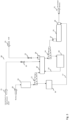
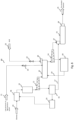
Fig. 3 , a further embodiment of the present invention will be described. Thesystem 30 includes a storage unit, e.g. a silo, 11 to which thelignocellulosic biomass 24, for example, wet biomass having a moisture content in the range of 5 - 80 %, in embodiments the DM (dry matter/dry material) is about 40-45%, and a temperature in a range of about 20 - 40°C is provided. - Thereafter, the biomass material is fed further to a first
de-watering stage 12, for example a least onefeed screw 12, e.g. a plug screw feeder. In embodiments of the present invention, the biomass material has about 45-70% DM, or preferably about 50-60%, after thede-watering stage 12. The filtrate from thede-watering stage 12 is led to a collector unit orfiltrate tank 16 for use in the process. A screening stage may be arranged up-stream thefiltrate tank 16 in order to collect any solids that has passed through the de-watering screens together with the filtrate. The solids may then be recirculated back into the raw material flow, for example, to thestorage vessel 11. - The de-watered biomass material is fed further to an
addition stage 13 where chemicals, such ase.g. acidifying chemicals 23, is added via anacid spraying system 26 and/orsteam 21, e.g. high pressure steam at a pressure of about 650 - 4000 kPa or low-pressure steam at a pressure of about 90 - 1200 kPa, is added via avalve 20. In embodiments of the present invention, the addition stage may comprise an impregnator, a soaking unit or a mixer screw or a PREX-impregnation system (a Valmet product). A DM may be about 25 - 45% or, preferably, about 30 - 35% after theaddition stage 13. - A
filtrate feeding arrangement 17 is arranged to feed filtrate from thefiltrate tank 16 to areactor stage 15, e.g. apre-hydrolysis reactor 15. In this embodiment, the filtrate is fed to adischarge part 28 of thereactor stage 15, e.g. to clean a discharge screw is there one arranged in thereactor 15, or to clean thedischarge part 28 and/or to dilute the discharged treated biomass. - A second
de-watering stage 14 may be provided down-stream theaddition stage 13 and up-stream thereactor stage 15. Thereactor stage 15 and theaddition stage 13 may be operatively coupled to the secondde-watering stage 14. The biomass material has about 45-70% DM, or preferably about 50-60%, after the secondde-watering stage 14. The filtrate may be led to afiltrate tank 18 for use in the process. Ascreening stage 37, shown inFig. 6 , may be arranged up-stream thefiltrate tank 18 in order to collect any solids that has passed through the de-watering screens together with the filtrate, as described below in connection withFig. 6 . The collected filtrate may be fed back into the loop in theaddition stage 13 via are-circulation arrangement 19. - Turning now to
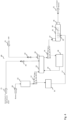
Fig. 4 , yet another embodiment of the present invention will be described. Thesystem 40 includes a storage unit, e.g. a silo, 11 to which thelignocellulosic biomass 24, for example, wet biomass having a moisture content in the range of 5 - 80 %, in embodiments the DM (dry matter/dry material) is about 40-45%, and a temperature in a range of about 20 - 40°C is provided. - The biomass material is thereafter fed further to a first
de-watering stage 12, for example a least onefeed screw 12, e.g. a plug screw feeder. In embodiments of the present invention, the biomass material has about 45-70% DM, or preferably about 50-60%, after thede-watering stage 12. The filtrate from thede-watering stage 12 is led to a collector unit orfiltrate tank 16 for use in the process. A screening stage may be arranged up-stream thefiltrate tank 16 in order to collect any solids that has passed through the de-watering screens together with the filtrate. The solids may then be recirculated back into the raw material flow, for example, to thestorage vessel 11. - The de-watered biomass material is fed further to an
addition stage 13 where chemicals, such ase.g. acidifying chemicals 23, is added via anacid spraying system 26 and/orsteam 21, e.g. high pressure steam at a pressure of about 650 - 4000 kPa or low-pressure steam at a pressure of about 90 - 1200 kPa, is added via avalve 20. In embodiments of the present invention, the addition stage may comprise an impregnator, a soaking unit or a mixer screw, or a PREX-impregnation system (a Valmet product). A DM may be about 25 - 45% or, preferably, about 30 - 35% after theaddition stage 13. - A
filtrate feeding arrangement 17 is arranged to feed filtrate from thefiltrate tank 16 to areactor stage 15, e.g. apre-hydrolysis reactor 15. In this embodiment, the filtrate is fed to cleaningnozzles 29 of the reactor stage to clean areactor screw 34. - A second
de-watering stage 14 may be provided down-stream theaddition stage 13 and up-stream thereactor stage 15. Thereactor stage 15 and theaddition stage 13 may be operatively coupled to the secondde-watering stage 14. The biomass material has about 45-70% DM, or preferably about 50-60%, after the secondde-watering stage 14. The filtrate may be led to afiltrate tank 18 for use in the process. A screening stage may be arranged up-stream thefiltrate tank 18 in order to collect any solids that has passed through the de-watering screens together with the filtrate, as described below in connection withFig. 5 . The collected filtrate may be fed back into the loop in theaddition stage 13 via are-circulation arrangement 19. - With reference now to
Fig. 5 , another embodiment of a system according to the present invention will be described. - The
system 50 includes a storage unit, e.g. a silo, 11 to which thelignocellulosic biomass 24, for example, wet biomass having a moisture content in the range of 5 - 80 %, in embodiments the DM (dry matter/dry material) is about 40-45%, and a temperature in a range of about 20 - 40°C is provided. The biomass material is thereafter fed further to a firstde-watering stage 12, for example a least onefeed screw 12, e.g. a plug screw feeder. In embodiments of the present invention, the biomass material has about 45-70% DM, or preferably about 50-60%, after thede-watering stage 12. The filtrate from thede-watering stage 12 is led to a collector unit orfiltrate tank 16 for use in the process. A screening stage may be arranged up-stream thefiltrate tank 16 in order to collect any solids that has passed through the de-watering screens together with the filtrate. The solids may then be recirculated back into the raw material flow, for example, to thestorage vessel 11. - The de-watered biomass material is fed further to an
addition stage 13 where chemicals, such ase.g. acidifying chemicals 23, is added via anacid spraying system 26 and/orsteam 21, e.g. high pressure steam at a pressure of about 650 - 4000 kPa or low-pressure steam at a pressure of about 90 - 1200 kPa, is added via avalve 20. In embodiments of the present invention, the addition stage may comprise an impregnator, a soaking unit or a mixer screw, or a PREX-impregnation system (a Valmet product). A DM may be about 25 - 45% or, preferably, about 30 - 35% after theaddition stage 13. - A
filtrate feeding arrangement 17 is arranged to feed filtrate from thefiltrate tank 16 to areactor stage 15, e.g. apre-hydrolysis reactor 15. In this embodiment, the filtrate is fed to the reactor stage, e.g. aninlet 27 of thereactor stage 15, e.g. to be sprayed over the incoming biomass material, and via a secondfiltrate feeding arrangement 35 to theacid spraying system 26 if more liquid is need to maintain a balance in the added liquid. - A second
de-watering stage 14 may be provided down-stream theaddition stage 13 and up-stream thereactor stage 15. Thereactor stage 15 and theaddition stage 13 may be operatively coupled to the secondde-watering stage 14. The biomass material has about 45-70% DM, or preferably about 50-60%, after the secondde-watering stage 14. The filtrate may be led to afiltrate tank 18 for use in the process. A screening stage may be arranged up-stream thefiltrate tank 18 in order to collect any solids that has passed through the de-watering screens together with the filtrate, as described below in connection withFig. 6 . The collected filtrate may be fed back into the loop in theaddition stage 13 via are-circulation arrangement 19. - With reference now to
Fig. 6 , a further embodiment of the system according to the present invention will be described. - The
system 60 includes a storage unit, e.g. a silo, 11 to which thelignocellulosic biomass 24, for example, wet biomass having a moisture content in the range of 5 - 80 %, in embodiments the DM (dry matter/dry material) is about 40-45%, and a temperature in a range of about 20 - 40°C is provided. The biomass material is thereafter fed further to a firstde-watering stage 12, for example a least onefeed screw 12, e.g. a plug screw feeder. In embodiments of the present invention, the biomass material has about 45-70% DM, or preferably about 50-60%, after thede-watering stage 12. The filtrate from thede-watering stage 12 is led to a collector unit orfiltrate tank 16 for use in the process. A screening stage may be arranged up-stream thefiltrate tank 16 in order to collect any solids that has passed through the de-watering screens together with the filtrate. The solids may then be recirculated back into the raw material flow, for example, to thestorage vessel 11. - The de-watered biomass material is fed further to an
addition stage 13 where chemicals, such ase.g. acidifying chemicals 23, is added via anacid spraying system 26 and/orsteam 21, e.g. high pressure steam at a pressure of about 650 - 4000 kPa or low-pressure steam at a pressure of about 90 - 1200 kPa, is added via avalve 20. In embodiments of the present invention, the addition stage may comprise an impregnator, a soaking unit or a mixer screw. A DM may be about 25 - 45% or, preferably, about 30 - 35% after theaddition stage 13. - A recovery and refining stage or
screening stage 33 is coupled to thefiltrate tank 16 to screen the filtrate to for example remove any solids present in the filtrate. The solids may then be recirculated to thebiomass material 24 provided into the process. Thereafter, the refined filtrate may be fed to thereactor stage 15 via thefiltrate feeding arrangement 17, for example, as described with reference toFig. 1 - 4 . - A second
de-watering stage 14 may be provided down-stream theaddition stage 13 and up-stream thereactor stage 15. Thereactor stage 15 and theaddition stage 13 may be operatively coupled to the secondde-watering stage 14. The biomass material has about 45-70% DM, or preferably about 50-60%, after the secondde-watering stage 14. The filtrate may be led to afiltrate tank 18 for use in the process. A recovery and refining orscreening stage 37 is arranged up-stream thefiltrate tank 18 in order to collect any solids that has passed through the de-watering screens together with the filtrate. Thereafter, the collected filtrate may be fed back into the loop in theaddition stage 13 via are-circulation arrangement 19. - With reference to
Fig. 7 , yet another embodiment of the system according to the present invention will be described. Thesystem 70 includes a storage unit, e.g. a silo, 11 to which thelignocellulosic biomass 24, for example, wet biomass, e.g. wood chips, having a moisture content in the range of 5 - 80 %, in embodiments the DM (dry matter/dry material) is about 40-45%, and a temperature in a range of about 20 - 40°C is provided. The biomass material is thereafter fed further to a firstde-watering stage 12, for example a least onefeed screw 12, e.g. a plug screw feeder. In embodiments of the present invention, the biomass material has about 45-70% DM, or preferably about 50-60%, after thede-watering stage 12. The filtrate from thede-watering stage 12 is led to a collector unit orfiltrate tank 16 for use in the process. Ascreening stage 33 is arranged up-stream thefiltrate tank 16 in order to collect any solids that has passed through the de-watering screens together with the filtrate. The solids may then be recirculated back into the raw material flow, for example, to thestorage vessel 11. - The de-watered biomass material is fed further to an
addition stage 13 where chemicals, such ase.g. acidifying chemicals 23, is added via anacid spraying system 26 and/orsteam 21, e.g. high pressure steam at a pressure of about 650 - 4000 kPa or low-pressure steam at a pressure of about 90 - 1200 kPa, is added via avalve 20. In embodiments of the present invention, the addition stage may comprise an impregnator, a soaking unit or a mixer screw. A DM may be about 25 - 45% or, preferably, about 30 - 35% after theaddition stage 13. - Hence, a recovery and refining stage or
screening stage 33 is coupled to thefiltrate tank 16 to screen the filtrate to for example remove any solids present in the filtrate. The solids may then be recirculated to thebiomass material 24 provided into the process. Thereafter, the refined filtrate is be fed to thereactor stage 15 via thefiltrate feeding arrangement 17, for example, as described with reference toFig. 2-5 . In embodiments of the present invention, a main part of the refined filtrate is fed to thereactor stage 15 and a fraction of the filtrate, for example, 1 - 5% is fed upstream in the process, for example, to the storage vessel orsilo 11 as shown inFig. 7 and/or to araw material washer 38, or biomass washer, or wood chip washer as in thesystem 80 shown inFig. 8 . - A second
de-watering stage 14 may be provided down-stream theaddition stage 13 and up-stream thereactor stage 15. Thereactor stage 15 and theaddition stage 13 may be operatively coupled to the secondde-watering stage 14. The biomass material has about 45-70% DM, or preferably about 50-60%, after the secondde-watering stage 14. The filtrate may be led to afiltrate tank 18 for use in the process. A recovery and refining orscreening stage 33 is arranged up-stream thefiltrate tank 18 in order to collect any solids that has passed through the de-watering screens together with the filtrate. Thereafter, the collected filtrate may be fed back into the loop in theaddition stage 13 via are-circulation arrangement 19. - With reference to
Fig. 9 , yet another embodiment of the system according to the present invention will be described. Thesystem 90 includes a storage unit, e.g. a silo, 11 to which thelignocellulosic biomass 24, for example, wet biomass, e.g. wood chips, having a moisture content in the range of 5 - 80 %, in embodiments the DM (dry matter/dry material) is about 40-45%, and a temperature in a range of about 20 - 40°C is provided. The biomass material is thereafter fed further to a firstde-watering stage 12, for example a least onefeed screw 12, e.g. a plug screw feeder. In embodiments of the present invention, the biomass material has about 45-70% DM, or preferably about 50-60%, after thede-watering stage 12. The filtrate from thede-watering stage 12 is led to a collector unit orfiltrate tank 16 for use in the process. Ascreening stage 33 is arranged up-stream thefiltrate tank 16 in order to collect any solids that has passed through the de-watering screens together with the filtrate. The solids may then be recirculated back into the raw material flow, for example, to thestorage vessel 11. - The de-watered biomass material is fed further to an
addition stage 13 where chemicals, such ase.g. acidifying chemicals 23, is added via anacid spraying system 26 and/orsteam 21, e.g. high pressure steam at a pressure of about 650 - 4000 kPa or low-pressure steam at a pressure of about 90 - 1200 kPa, is added via avalve 20. In embodiments of the present invention, the addition stage may comprise an impregnator, a soaking unit or a mixer screw. A DM may be about 25 - 45% or, preferably, about 30 - 35% after theaddition stage 13. - Hence, a recovery and refining stage or
screening stage 33 is coupled to thefiltrate tank 16 to screen the filtrate to for example remove any solids present in the filtrate. The solids may then be recirculated to thebiomass material 24 provided into the process. Thereafter, the refined filtrate is be fed to thereactor stage 15 via thefiltrate feeding arrangement 17, for example, as described with reference toFig. 2-5 . For example, the filtrate may be fed to adischarge part 28 of thereactor stage 15, e.g. to clean a discharge screw is there one arranged in thereactor 15, or to clean thedischarge part 28 and/or to dilute the discharged treated biomass, or to cleaningnozzles 29 arranged in the reactor vessel to clean areactor screw 34, or to aninlet 27 of thereactor stage 15, e.g. to be sprayed over the incoming biomass material, and/or via a secondfiltrate feeding arrangement 35 to theacid spraying system 26 if more liquid is need to maintain a balance in the added liquid. - In embodiments of the present invention, a main part of the refined filtrate is fed to the
reactor stage 15 and a fraction of the filtrate, for example, 1 - 5% is fed upstream in the process, for example, to the storage vessel orsilo 11 and/or to araw material washer 38, or biomass washer, or wood chip washer. - A second
de-watering stage 14 may be provided down-stream theaddition stage 13 and up-stream thereactor stage 15. Thereactor stage 15 and theaddition stage 13 may be operatively coupled to the secondde-watering stage 14. The biomass material has about 45-70% DM, or preferably about 50-60%, after the secondde-watering stage 14. The filtrate may be led to afiltrate tank 18 for use in the process. A recovery and refining orscreening stage 33 is arranged up-stream thefiltrate tank 18 in order to collect any solids that has passed through the de-watering screens together with the filtrate. Thereafter, the collected filtrate may be fed back into the loop in theaddition stage 13 via are-circulation arrangement 19. - With reference to
Fig. 10 , a method according to an embodiment of the present invention will be described. The method relates to treatment and feeding of lignocellulosic biomass which is treated at elevated temperature and pressure with steam or mixtures of steam and acidifying solutions. The lignocellulosic biomass material, such as wood chips, may be treated in different processes, such as a soaking process, before feeding the biomass material to a storage vessel, bin orsilo 11. Thebiomass material 24 provided into the process may be, for example, wood chips of softwood or hardwood, sawdust, grasses, straw, bagasse, kenaf, or other forms of agricultural waste or a combination thereof. The lignocellulosic biomass may, for example, be wet biomass may have a moisture content in the range of 5 - 80 %, in embodiments the DM (dry matter/dry material) is about 40-45%, and may have a temperature in a range of about 20 - 40°C. - In the
process 100, thelignocellulosic biomass material 24 is fed, atstep 111 to asilo 11. Thereafter, atstep 112, liquid is removed from the biomass in a firstde-watering stage 12, for example a least onefeed screw 12, e.g. a plug screw feeder. In embodiments of the present invention, the biomass material has about 45-70% DM, or preferably about 50-60%, after thede-watering stage 12. - At
step 113, the filtrate from thede-watering stage 12 is collected and provided towater treatment 117. - At
step 114, an addition step is performed in anaddition stage 13 where chemicals, such ase.g. acidifying chemicals 23, is added via anacid spraying system 26 and/orsteam 21, e.g. high pressure steam at a pressure of about 650 - 4000 kPa or low-pressure steam at a pressure of about 90 - 1200 kPa, is added via avalve 20. In embodiments of the present invention, the addition stage may comprise an impregnator, a soaking unit or a mixer screw. A DM may be about 25 - 45% or, preferably, about 30 - 35% after theaddition stage 13. - At
step 115, a treatment process in areactor stage 15 is performed, e.g. a pre-hydrolysis process, on the biomass material. - At
step 116, the treated biomass material may be fed to further processing steps. - Referring now to
Fig. 11 , another embodiment of the method according to the present invention will be described. In theprocess 200, thelignocellulosic biomass material 24 is fed, atstep 211 to asilo 11. Thereafter, atstep 212, liquid is removed from the biomass in a firstde-watering stage 12, for example a least onefeed screw 12, e.g. a plug screw feeder. In embodiments of the present invention, the biomass material has about 45-70% DM, or preferably about 50-60%, after thede-watering stage 12. - At
step 213, the filtrate from thede-watering stage 12 is collected in a collector unit orfiltrate tank 16 for use in the process. - At
step 214, an addition step is performed in anaddition stage 13 where chemicals, such ase.g. acidifying chemicals 23, is added via anacid spraying system 26 and/orsteam 21, e.g. high pressure steam at a pressure of about 650 - 4000 kPa or low-pressure steam at a pressure of about 90 - 1200 kPa, is added via avalve 20. In embodiments of the present invention, the addition stage may comprise an impregnator, a soaking unit or a mixer screw. A DM may be about 25 - 45% or, preferably, about 30 - 35% after theaddition stage 13. - At
step 215, a treatment process in areactor stage 15 is performed, e.g. a pre-hydrolysis process, on the biomass material. - At
step 217, the filtrate collected from the firstde-watering stage 12 is re-cycled or fed to thereactor stage 15 using afiltrate feeding arrangement 17 arranged to feed filtrate from thefiltrate tank 16 to thereactor stage 15, e.g. apre-hydrolysis reactor 15. For example, the filtrate may be fed to adischarge part 28 of thereactor stage 15, e.g. to clean a discharge screw is there one arranged in thereactor 15, or to clean thedischarge part 28 and/or to dilute the discharged treated biomass, or to cleaningnozzles 29 arranged in the reactor vessel to clean areactor screw 34, or to aninlet 27 of thereactor stage 15, e.g. to be sprayed over the incoming biomass material, and/or via a secondfiltrate feeding arrangement 35 to theacid spraying system 26 if more liquid is need to maintain a balance in the added liquid. - At
step 216, the treated biomass material may be fed to further processing steps. - With reference to
Fig. 12 , yet another method according to the present invention will be described. The method relates to treatment and feeding of lignocellulosic biomass which is treated at elevated temperature and pressure with steam or mixtures of steam and acidifying solutions. The lignocellulosic biomass material may be treated in different processes, such as a soaking process, before feeding the biomass material to a storage vessel, bin orsilo 11. Thebiomass material 24 provided into the process may be, for example, wood chips of softwood or hardwood, sawdust, grasses, straw, bagasse, kenaf, or other forms of agricultural waste or a combination thereof. The lignocellulosic biomass may, for example, be wet biomass may have a moisture content in the range of 5 - 80 %, in embodiments the DM (dry matter/dry material) is about 40-45%, and may have a temperature in a range of about 20 - 40°C. - In the
process 300, thelignocellulosic biomass material 24 is fed, atstep 311 to asilo 11. Thereafter, atstep 312, liquid is removed from the biomass in a firstde-watering stage 12, for example a least onefeed screw 12, e.g. a plug screw feeder. In embodiments of the present invention, the biomass material has about 45-70% DM, or preferably about 50-60%, after thede-watering stage 12. - At
step 313, the filtrate from thede-watering stage 12 is collected in a collector unit orfiltrate tank 16 for use in the process. - At
step 314, an addition step is performed in anaddition stage 13 where chemicals, such ase.g. acidifying chemicals 23, is added via anacid spraying system 26 and/orsteam 21, e.g. high pressure steam at a pressure of about 650 - 4000 kPa or low-pressure steam at a pressure of about 90 - 1200 kPa, is added via avalve 20. In embodiments of the present invention, the addition stage may comprise an impregnator, a soaking unit or a mixer screw. A DM may be about 25 - 45% or, preferably, about 30 - 35% after theaddition stage 13. - At
step 315, a second de-watering step is performed down-stream theaddition stage 13. The biomass material has about 45-70% DM, or preferably about 50-60%, after the secondde-watering stage 14. The filtrate may be led to afiltrate tank 18 for use in the process. A screening stage may be arranged up-stream thefiltrate tank 18 in order to collect any solids that has passed through the de-watering screens together with the filtrate, as described below in connection withFig. 5 . Atstep 318, the collected filtrate is recycled into the process loop in theaddition stage 13 via are-circulation arrangement 19. - At
step 316, a treatment process in areactor stage 15 is performed, e.g. a pre-hydrolysis process, on the biomass material. - At
step 319, the filtrate collected from the firstde-watering stage 12 is re-cycled or fed to thereactor stage 15 using afiltrate feeding arrangement 17 arranged to feed filtrate from thefiltrate tank 16 to thereactor stage 15, e.g. apre-hydrolysis reactor 15. For example, the filtrate may be fed to adischarge part 28 of thereactor stage 15, e.g. to clean a discharge screw is there one arranged in thereactor 15, or to clean thedischarge part 28 and/or to dilute the discharged treated biomass, or to cleaningnozzles 29 arranged in the reactor vessel to clean areactor screw 34, or to aninlet 27 of thereactor stage 15, e.g. to be sprayed over the incoming biomass material, and/or via a secondfiltrate feeding arrangement 35 to theacid spraying system 26 if more liquid is need to maintain a balance in the added liquid. - At
step 317, the treated biomass material may be fed to further processing steps.
Claims (15)
- A treatment process system (10; 20; 30; 40; 50) for biomass material comprisinga first dewatering stage (12) arranged to receive biomass material, to remove liquid from the biomass material, and to feed the biomass material forward in the process;a first filtrate tank (16) arranged to receive and collect the liquid removed in the first dewatering stage (12);an addition stage (13) located downstream said dewatering stage (12) and operatively coupled to the first dewatering stage (12), said addition stage (13) being arranged to receive the dewatered biomass material, wherein said addition stage (13) includes inlets (20, 22) for adding acid containing solution (23) into the addition stage (13), wherein the addition stage comprises an impregnator, or a soaking unit, or a mixer screw; anda reactor stage (15) arranged to receive the biomass material treated in the addition stage (13) and to perform a pre-hydrolysis process to the biomass material; said system being characterized bya filtrate feeding arrangement (17) arranged to feed liquid from the filtrate tank (16) to the reactor stage (15), wherein liquid collected from the first dewatering stage (12) is re-cycled to the reactor stage (15).
- A treatment process system (30) according to claim 1, wherein the filtrate feeding arrangement (17) is arranged to provide liquid from the filtrate tank (16) to cleaning nozzles (29) of the reactor stage (15).
- A treatment process system (20) according to any one of preceding claims, wherein the filtrate feeding arrangement (17) is arranged to provide liquid from the filtrate tank (16) to a discharge unit (28) of the reactor stage (15).
- A treatment process system (40) according to any one or preceding claims, wherein the filtrate feeding arrangement (17) is arranged to provide liquid from the filtrate tank (16) to an inlet part (27) of the reactor stage (15).
- A treatment process system (10; 20; 30; 40; 50; 60; 70; 80; 90) according to any one of preceding claims, further comprising a second dewatering stage (14) located downstream said addition stage (13) and operatively coupled to the addition stage (13), said second dewatering stage (14) being arranged to receive biomass material, to remove liquid from the biomass material, and to feed the biomass material forward in the process.
- A treatment process system (10; 20; 30; 40; 50; 60; 70; 80; 90) according to ay one of preceding claims, further comprising:a second filtrate tank (18) arranged to collect removed liquid from the second dewatering stage (14); anda re-circulation arrangement (19) arranged to feed liquid from the second filtrate tank (18) to the addition stage (13).
- A treatment process system (10; 20; 30; 40; 50; 60; 70; 80; 90) according to any one of preceding claims, comprising a pre-steaming stage (31) located up-stream said first de-watering stage (12), said pre-steaming stage (31) being arranged to perform a pre-steaming process on said biomass material.
- A treatment process system (10; 20; 30; 40; 50; 60; 70; 80; 90) according to any one of preceding claims, comprising a recovery and refining stage (33) coupled to said first filtrate tank (16) arranged to perform a refining process on the filtrate to recover selected compounds from the filtrate.
- A treatment process (100; 200; 300) for biomass material comprising the steps of:removing (112; 212; 312) liquid from the biomass material in a first de-watering stage (12);collecting (113; 213; 313) the removed liquid from the first de-watering stage (12);after said removing, adding (114; 214; 314) an acid containing solution to the biomass material in an addition stage comprising an impregnator, or a soaking unit, or a mixer screw; andafter said adding, performing (115; 215; 316) a pre-hydrolysis process in a reactor stage (15) on the biomass material; said process being characterized inrecycling (217; 319) the collected liquid from first de-watering stage (12) to the reactor stage (15).
- A treatment process (200; 300) for biomass material according to claim 9, further comprising feeding liquid collected liquid from the first dewatering stage to cleaning nozzles (29) of the reactor stage (15).
- A treatment process (200; 300) according to claim 9 or 10,
further comprising feeding liquid collected liquid from the first dewatering stage to a discharge unit (28) of the reactor stage (15). - A treatment process (200; 300) according to claim 9 - 11, further comprising feeding liquid collected liquid from the first dewatering stage to an inlet part (27) of the reactor stage (15).
- A treatment process (300) according to claim 9 - 12, further comprising:removing (315) liquid from the biomass material in a second de-watering stage (18);collecting (315) the removed liquid from the second de-watering stage (12); andrecycling (318) the collected liquid from second de-watering stage (18) to the addition stage (13).
- A treatment process (100; 200; 300) according to claim 9 - 13,
further comprising performing pre-steaming up-stream the first de-watering stage (12). - A treatment process (100; 200; 300) according to claim 9 - 14,
further comprising performing a refining process on the filtrate to recover selected compounds from the filtrate.
Applications Claiming Priority (2)
| Application Number | Priority Date | Filing Date | Title |
|---|---|---|---|
| SE1851014A SE543418C2 (en) | 2018-08-24 | 2018-08-24 | Systems and methods for treating biomass material in prehydrolysis |
| PCT/SE2019/050500 WO2020040677A1 (en) | 2018-08-24 | 2019-05-29 | System and method for treating biomass material |
Publications (3)
| Publication Number | Publication Date |
|---|---|
| EP3841245A1 EP3841245A1 (en) | 2021-06-30 |
| EP3841245A4 EP3841245A4 (en) | 2022-06-15 |
| EP3841245B1 true EP3841245B1 (en) | 2024-03-06 |
Family
ID=69592768
Family Applications (1)
| Application Number | Title | Priority Date | Filing Date |
|---|---|---|---|
| EP19852122.1A Active EP3841245B1 (en) | 2018-08-24 | 2019-05-29 | System and method for treating biomass material |
Country Status (5)
| Country | Link |
|---|---|
| US (1) | US11946090B2 (en) |
| EP (1) | EP3841245B1 (en) |
| FI (1) | FI3841245T3 (en) |
| SE (1) | SE543418C2 (en) |
| WO (1) | WO2020040677A1 (en) |
Families Citing this family (3)
| Publication number | Priority date | Publication date | Assignee | Title |
|---|---|---|---|---|
| SE543418C2 (en) * | 2018-08-24 | 2021-01-12 | Valmet Oy | Systems and methods for treating biomass material in prehydrolysis |
| SE545274C2 (en) * | 2020-06-08 | 2023-06-13 | Valmet Oy | A pre-hydrolysis pressure vessel system comprising a cleaning arrangement |
| CN114479975B (en) * | 2021-12-29 | 2024-12-27 | 秦皇岛开发区秦综开泰园区服务有限责任公司 | Biomass energy raw material separation processing equipment |
Citations (14)
| Publication number | Priority date | Publication date | Assignee | Title |
|---|---|---|---|---|
| WO2004005608A1 (en) | 2002-07-02 | 2004-01-15 | Andritz, Inc. | Solvent pulping of biomass |
| US20090061495A1 (en) * | 2007-08-31 | 2009-03-05 | Chris Beatty | Treatment Systems and Processes for Lignocellulosic Substrates that Contain Soluble Carbohydrates |
| WO2010022511A1 (en) | 2008-08-29 | 2010-03-04 | Iogen Energy Corporation | Method for low water hydrolysis or pretreatment of polysaccharides in a lignocellulosic feedstock |
| US20110281298A1 (en) | 2010-05-11 | 2011-11-17 | Andritz Inc. | Method and apparatus to extracted and reduce dissolved hemi-cellulosic solids in biomass following pre-hydrolysis |
| JP2012000022A (en) | 2010-06-15 | 2012-01-05 | Tsukishima Kikai Co Ltd | Biomass processing device and method |
| US20120211183A1 (en) | 2011-02-22 | 2012-08-23 | Andritz Inc. | Method and apparatus to produce pulp using pre-hydrolysis and kraft cooking |
| US20130029406A1 (en) | 2011-07-28 | 2013-01-31 | Greenfield Ethanol Inc. | Two stage continuous pre-treatment of lignocellulosic biomass |
| WO2013186184A1 (en) | 2012-06-13 | 2013-12-19 | Voith Patent Gmbh | Method for removing liquid from a slurry |
| US20140288298A1 (en) | 2011-11-30 | 2014-09-25 | Oji Holdings Corporation | Method for manufacturing monosaccharides, oligosaccharides, and furfurals from biomass |
| WO2015199604A1 (en) | 2014-06-26 | 2015-12-30 | Valmet Ab | Arrangement and system for a treatment process |
| US20160076198A1 (en) | 2014-09-12 | 2016-03-17 | Bio Ag Resources, Inc. | Systems, devices and methods for agricultural product pulping |
| WO2017088061A1 (en) | 2015-11-25 | 2017-06-01 | Iogen Energy Corporation | System and method for cooling pretreated biomass |
| EP3333310A1 (en) | 2016-12-08 | 2018-06-13 | Valmet AB | Method and system for treating biomass |
| WO2018202673A1 (en) | 2017-05-02 | 2018-11-08 | Valmet Ab | Method and device for treating biomass |
Family Cites Families (3)
| Publication number | Priority date | Publication date | Assignee | Title |
|---|---|---|---|---|
| CA2838756C (en) * | 2011-06-28 | 2021-02-23 | Iogen Energy Corporation | Method for reducing water usage in a cellulosic conversion process |
| SE537195C2 (en) | 2012-02-22 | 2015-03-03 | Valmet Oy | Feeding device, system and method for handling non-wood based plant material |
| SE543418C2 (en) * | 2018-08-24 | 2021-01-12 | Valmet Oy | Systems and methods for treating biomass material in prehydrolysis |
-
2018
- 2018-08-24 SE SE1851014A patent/SE543418C2/en unknown
-
2019
- 2019-05-29 US US17/267,590 patent/US11946090B2/en active Active
- 2019-05-29 FI FIEP19852122.1T patent/FI3841245T3/en active
- 2019-05-29 EP EP19852122.1A patent/EP3841245B1/en active Active
- 2019-05-29 WO PCT/SE2019/050500 patent/WO2020040677A1/en not_active Ceased
Patent Citations (14)
| Publication number | Priority date | Publication date | Assignee | Title |
|---|---|---|---|---|
| WO2004005608A1 (en) | 2002-07-02 | 2004-01-15 | Andritz, Inc. | Solvent pulping of biomass |
| US20090061495A1 (en) * | 2007-08-31 | 2009-03-05 | Chris Beatty | Treatment Systems and Processes for Lignocellulosic Substrates that Contain Soluble Carbohydrates |
| WO2010022511A1 (en) | 2008-08-29 | 2010-03-04 | Iogen Energy Corporation | Method for low water hydrolysis or pretreatment of polysaccharides in a lignocellulosic feedstock |
| US20110281298A1 (en) | 2010-05-11 | 2011-11-17 | Andritz Inc. | Method and apparatus to extracted and reduce dissolved hemi-cellulosic solids in biomass following pre-hydrolysis |
| JP2012000022A (en) | 2010-06-15 | 2012-01-05 | Tsukishima Kikai Co Ltd | Biomass processing device and method |
| US20120211183A1 (en) | 2011-02-22 | 2012-08-23 | Andritz Inc. | Method and apparatus to produce pulp using pre-hydrolysis and kraft cooking |
| US20130029406A1 (en) | 2011-07-28 | 2013-01-31 | Greenfield Ethanol Inc. | Two stage continuous pre-treatment of lignocellulosic biomass |
| US20140288298A1 (en) | 2011-11-30 | 2014-09-25 | Oji Holdings Corporation | Method for manufacturing monosaccharides, oligosaccharides, and furfurals from biomass |
| WO2013186184A1 (en) | 2012-06-13 | 2013-12-19 | Voith Patent Gmbh | Method for removing liquid from a slurry |
| WO2015199604A1 (en) | 2014-06-26 | 2015-12-30 | Valmet Ab | Arrangement and system for a treatment process |
| US20160076198A1 (en) | 2014-09-12 | 2016-03-17 | Bio Ag Resources, Inc. | Systems, devices and methods for agricultural product pulping |
| WO2017088061A1 (en) | 2015-11-25 | 2017-06-01 | Iogen Energy Corporation | System and method for cooling pretreated biomass |
| EP3333310A1 (en) | 2016-12-08 | 2018-06-13 | Valmet AB | Method and system for treating biomass |
| WO2018202673A1 (en) | 2017-05-02 | 2018-11-08 | Valmet Ab | Method and device for treating biomass |
Non-Patent Citations (4)
| Title |
|---|
| "Kraft process: An overview", 2 July 2023 (2023-07-02), Retrieved from the Internet <URL:www.sciencedirect.com/topics/engineering/kraft-process> * |
| CARRASCO F. ET AL: "Kinetic study of dilute-acid prehydrolysis of xylan-containing biomass", WOOD SCIENCE AND TECHNOLOGY, vol. 26, no. 3, 1 March 1992 (1992-03-01), DE, pages 189 - 208, XP093058105, ISSN: 0043-7719, DOI: 10.1007/BF00224292 * |
| DEVI ARTI ET AL: "Lignocellulosic Biomass Valorization for Bioethanol Production: a Circular Bioeconomy Approach", vol. 15, no. 4, 7 February 2022 (2022-02-07), Boston, pages 1820 - 1841, XP093058074, ISSN: 1939-1234, Retrieved from the Internet <URL:https://link.springer.com/article/10.1007/s12155-022-10401-9/fulltext.html> DOI: 10.1007/s12155-022-10401-9 * |
| DEVI ARTI, BAJAR SOMVIR, KOUR HAVLEEN, KOTHARI RICHA, PANT DEEPAK, SINGH ANITA: "Lignocellulosic Biomass Valorization for Bioethanol Production: a Circular Bioeconomy Approach", BIOENERGY RESEARCH, SPRINGER US, BOSTON, vol. 15, no. 4, 1 December 2022 (2022-12-01), Boston , pages 1820 - 1841, XP093058074, ISSN: 1939-1234, DOI: 10.1007/s12155-022-10401-9 |
Also Published As
| Publication number | Publication date |
|---|---|
| WO2020040677A1 (en) | 2020-02-27 |
| EP3841245A4 (en) | 2022-06-15 |
| FI3841245T3 (en) | 2024-04-17 |
| US20210310029A1 (en) | 2021-10-07 |
| US11946090B2 (en) | 2024-04-02 |
| EP3841245A1 (en) | 2021-06-30 |
| SE543418C2 (en) | 2021-01-12 |
| SE1851014A1 (en) | 2020-02-25 |
Similar Documents
| Publication | Publication Date | Title |
|---|---|---|
| EP3841245B1 (en) | System and method for treating biomass material | |
| CA1245011A (en) | Countercurrent acid hydrolysis | |
| US9333468B2 (en) | Soak vessels and methods for impregnating biomass with liquid | |
| US20110281298A1 (en) | Method and apparatus to extracted and reduce dissolved hemi-cellulosic solids in biomass following pre-hydrolysis | |
| CN105672012B (en) | The method for extracting hemicellulose, cellulose and lignin simultaneously from biomass material | |
| JP2012514972A (en) | Method and apparatus for feeding substances into a process reactor | |
| US20210017210A1 (en) | Methods of recovering lignin and other products from biomass | |
| US9169524B2 (en) | Universal biomass refinery | |
| US11565272B2 (en) | System and method for treating biomass material | |
| EP4413094A1 (en) | A process for production of fossil free hydrocarbons from lignocellulosic material | |
| RU2750146C2 (en) | Methods for obtaining bioplastics and bioproducts from manure | |
| EP3656865B1 (en) | Method for cooling biomass | |
| US20230002971A1 (en) | Method and plant for obtaining cellulose fibres | |
| CN105502794B (en) | A kind of pH adjusting methods of anaerobic fermented liquid | |
| DK181708B1 (en) | Method and apparatus for pretreatment of a biomass comprising lignocellulosic fibers | |
| CN109505178B (en) | A kind of cooking method for preparing cellulose from three agricultural and forestry residues | |
| EP3663460B1 (en) | Improved process for pretreating biomass | |
| US7282115B2 (en) | Method for mitigating the interference caused by high-molecular weight-by-products in pulping processes | |
| CN105696397B (en) | Extract the device of hemicellulose, cellulose and lignin simultaneously from biomass material | |
| US20130224805A1 (en) | System and Method for Converting Cellulosic Biomass into a Sugar Solution | |
| EP4676664A1 (en) | Method and system for producing dealkalized lignocellulosic material and bio-based products | |
| JP2015167487A (en) | Producing method of ethanol from lignocellulose containing lignocellulose | |
| CN116034162A (en) | Apparatus and methods for processing lignocellulosic biomass | |
| WO2018080375A1 (en) | Method for producing ethanol and ethanol producing system |
Legal Events
| Date | Code | Title | Description |
|---|---|---|---|
| STAA | Information on the status of an ep patent application or granted ep patent |
Free format text: STATUS: THE INTERNATIONAL PUBLICATION HAS BEEN MADE |
|
| PUAI | Public reference made under article 153(3) epc to a published international application that has entered the european phase |
Free format text: ORIGINAL CODE: 0009012 |
|
| STAA | Information on the status of an ep patent application or granted ep patent |
Free format text: STATUS: REQUEST FOR EXAMINATION WAS MADE |
|
| 17P | Request for examination filed |
Effective date: 20210205 |
|
| AK | Designated contracting states |
Kind code of ref document: A1 Designated state(s): AL AT BE BG CH CY CZ DE DK EE ES FI FR GB GR HR HU IE IS IT LI LT LU LV MC MK MT NL NO PL PT RO RS SE SI SK SM TR |
|
| DAV | Request for validation of the european patent (deleted) | ||
| DAX | Request for extension of the european patent (deleted) | ||
| A4 | Supplementary search report drawn up and despatched |
Effective date: 20220518 |
|
| RIC1 | Information provided on ipc code assigned before grant |
Ipc: C12M 1/00 20060101ALI20220512BHEP Ipc: D21C 9/18 20060101ALI20220512BHEP Ipc: D21C 1/04 20060101AFI20220512BHEP |
|
| GRAP | Despatch of communication of intention to grant a patent |
Free format text: ORIGINAL CODE: EPIDOSNIGR1 |
|
| STAA | Information on the status of an ep patent application or granted ep patent |
Free format text: STATUS: GRANT OF PATENT IS INTENDED |
|
| TPAC | Observations filed by third parties |
Free format text: ORIGINAL CODE: EPIDOSNTIPA |
|
| GRAJ | Information related to disapproval of communication of intention to grant by the applicant or resumption of examination proceedings by the epo deleted |
Free format text: ORIGINAL CODE: EPIDOSDIGR1 |
|
| INTG | Intention to grant announced |
Effective date: 20230519 |
|
| RIN1 | Information on inventor provided before grant (corrected) |
Inventor name: PETTERSSON, PATRIK Inventor name: LOEFSTROEM, ANDERS Inventor name: CARLSSON, JOHAN Inventor name: AHLGREN, OERJAN |
|
| STAA | Information on the status of an ep patent application or granted ep patent |
Free format text: STATUS: REQUEST FOR EXAMINATION WAS MADE |
|
| TPAC | Observations filed by third parties |
Free format text: ORIGINAL CODE: EPIDOSNTIPA |
|
| STAA | Information on the status of an ep patent application or granted ep patent |
Free format text: STATUS: EXAMINATION IS IN PROGRESS |
|
| INTC | Intention to grant announced (deleted) | ||
| 17Q | First examination report despatched |
Effective date: 20230704 |
|
| GRAP | Despatch of communication of intention to grant a patent |
Free format text: ORIGINAL CODE: EPIDOSNIGR1 |
|
| STAA | Information on the status of an ep patent application or granted ep patent |
Free format text: STATUS: GRANT OF PATENT IS INTENDED |
|
| INTG | Intention to grant announced |
Effective date: 20231222 |
|
| GRAS | Grant fee paid |
Free format text: ORIGINAL CODE: EPIDOSNIGR3 |
|
| GRAA | (expected) grant |
Free format text: ORIGINAL CODE: 0009210 |
|
| STAA | Information on the status of an ep patent application or granted ep patent |
Free format text: STATUS: THE PATENT HAS BEEN GRANTED |
|
| AK | Designated contracting states |
Kind code of ref document: B1 Designated state(s): AL AT BE BG CH CY CZ DE DK EE ES FI FR GB GR HR HU IE IS IT LI LT LU LV MC MK MT NL NO PL PT RO RS SE SI SK SM TR |
|
| REG | Reference to a national code |
Ref country code: CH Ref legal event code: EP |
|
| REG | Reference to a national code |
Ref country code: IE Ref legal event code: FG4D |
|
| REG | Reference to a national code |
Ref country code: DE Ref legal event code: R096 Ref document number: 602019047973 Country of ref document: DE |
|
| REG | Reference to a national code |
Ref country code: FI Ref legal event code: FGE |
|
| REG | Reference to a national code |
Ref country code: SE Ref legal event code: TRGR |
|
| REG | Reference to a national code |
Ref country code: LT Ref legal event code: MG9D |
|
| PG25 | Lapsed in a contracting state [announced via postgrant information from national office to epo] |
Ref country code: LT Free format text: LAPSE BECAUSE OF FAILURE TO SUBMIT A TRANSLATION OF THE DESCRIPTION OR TO PAY THE FEE WITHIN THE PRESCRIBED TIME-LIMIT Effective date: 20240306 |
|
| REG | Reference to a national code |
Ref country code: NL Ref legal event code: MP Effective date: 20240306 |
|
| PG25 | Lapsed in a contracting state [announced via postgrant information from national office to epo] |
Ref country code: GR Free format text: LAPSE BECAUSE OF FAILURE TO SUBMIT A TRANSLATION OF THE DESCRIPTION OR TO PAY THE FEE WITHIN THE PRESCRIBED TIME-LIMIT Effective date: 20240607 |
|
| PG25 | Lapsed in a contracting state [announced via postgrant information from national office to epo] |
Ref country code: HR Free format text: LAPSE BECAUSE OF FAILURE TO SUBMIT A TRANSLATION OF THE DESCRIPTION OR TO PAY THE FEE WITHIN THE PRESCRIBED TIME-LIMIT Effective date: 20240306 Ref country code: RS Free format text: LAPSE BECAUSE OF FAILURE TO SUBMIT A TRANSLATION OF THE DESCRIPTION OR TO PAY THE FEE WITHIN THE PRESCRIBED TIME-LIMIT Effective date: 20240606 |
|
| PG25 | Lapsed in a contracting state [announced via postgrant information from national office to epo] |
Ref country code: ES Free format text: LAPSE BECAUSE OF FAILURE TO SUBMIT A TRANSLATION OF THE DESCRIPTION OR TO PAY THE FEE WITHIN THE PRESCRIBED TIME-LIMIT Effective date: 20240306 |
|
| PG25 | Lapsed in a contracting state [announced via postgrant information from national office to epo] |
Ref country code: RS Free format text: LAPSE BECAUSE OF FAILURE TO SUBMIT A TRANSLATION OF THE DESCRIPTION OR TO PAY THE FEE WITHIN THE PRESCRIBED TIME-LIMIT Effective date: 20240606 Ref country code: NO Free format text: LAPSE BECAUSE OF FAILURE TO SUBMIT A TRANSLATION OF THE DESCRIPTION OR TO PAY THE FEE WITHIN THE PRESCRIBED TIME-LIMIT Effective date: 20240606 Ref country code: LT Free format text: LAPSE BECAUSE OF FAILURE TO SUBMIT A TRANSLATION OF THE DESCRIPTION OR TO PAY THE FEE WITHIN THE PRESCRIBED TIME-LIMIT Effective date: 20240306 Ref country code: HR Free format text: LAPSE BECAUSE OF FAILURE TO SUBMIT A TRANSLATION OF THE DESCRIPTION OR TO PAY THE FEE WITHIN THE PRESCRIBED TIME-LIMIT Effective date: 20240306 Ref country code: GR Free format text: LAPSE BECAUSE OF FAILURE TO SUBMIT A TRANSLATION OF THE DESCRIPTION OR TO PAY THE FEE WITHIN THE PRESCRIBED TIME-LIMIT Effective date: 20240607 Ref country code: ES Free format text: LAPSE BECAUSE OF FAILURE TO SUBMIT A TRANSLATION OF THE DESCRIPTION OR TO PAY THE FEE WITHIN THE PRESCRIBED TIME-LIMIT Effective date: 20240306 Ref country code: BG Free format text: LAPSE BECAUSE OF FAILURE TO SUBMIT A TRANSLATION OF THE DESCRIPTION OR TO PAY THE FEE WITHIN THE PRESCRIBED TIME-LIMIT Effective date: 20240306 |
|
| REG | Reference to a national code |
Ref country code: AT Ref legal event code: MK05 Ref document number: 1663605 Country of ref document: AT Kind code of ref document: T Effective date: 20240306 |
|
| PG25 | Lapsed in a contracting state [announced via postgrant information from national office to epo] |
Ref country code: LV Free format text: LAPSE BECAUSE OF FAILURE TO SUBMIT A TRANSLATION OF THE DESCRIPTION OR TO PAY THE FEE WITHIN THE PRESCRIBED TIME-LIMIT Effective date: 20240306 |
|
| PG25 | Lapsed in a contracting state [announced via postgrant information from national office to epo] |
Ref country code: NL Free format text: LAPSE BECAUSE OF FAILURE TO SUBMIT A TRANSLATION OF THE DESCRIPTION OR TO PAY THE FEE WITHIN THE PRESCRIBED TIME-LIMIT Effective date: 20240306 |
|
| PG25 | Lapsed in a contracting state [announced via postgrant information from national office to epo] |
Ref country code: NL Free format text: LAPSE BECAUSE OF FAILURE TO SUBMIT A TRANSLATION OF THE DESCRIPTION OR TO PAY THE FEE WITHIN THE PRESCRIBED TIME-LIMIT Effective date: 20240306 |
|
| PG25 | Lapsed in a contracting state [announced via postgrant information from national office to epo] |
Ref country code: IS Free format text: LAPSE BECAUSE OF FAILURE TO SUBMIT A TRANSLATION OF THE DESCRIPTION OR TO PAY THE FEE WITHIN THE PRESCRIBED TIME-LIMIT Effective date: 20240706 |
|
| PG25 | Lapsed in a contracting state [announced via postgrant information from national office to epo] |
Ref country code: PT Free format text: LAPSE BECAUSE OF FAILURE TO SUBMIT A TRANSLATION OF THE DESCRIPTION OR TO PAY THE FEE WITHIN THE PRESCRIBED TIME-LIMIT Effective date: 20240708 Ref country code: SM Free format text: LAPSE BECAUSE OF FAILURE TO SUBMIT A TRANSLATION OF THE DESCRIPTION OR TO PAY THE FEE WITHIN THE PRESCRIBED TIME-LIMIT Effective date: 20240306 |
|
| PG25 | Lapsed in a contracting state [announced via postgrant information from national office to epo] |
Ref country code: CZ Free format text: LAPSE BECAUSE OF FAILURE TO SUBMIT A TRANSLATION OF THE DESCRIPTION OR TO PAY THE FEE WITHIN THE PRESCRIBED TIME-LIMIT Effective date: 20240306 Ref country code: EE Free format text: LAPSE BECAUSE OF FAILURE TO SUBMIT A TRANSLATION OF THE DESCRIPTION OR TO PAY THE FEE WITHIN THE PRESCRIBED TIME-LIMIT Effective date: 20240306 |
|
| PG25 | Lapsed in a contracting state [announced via postgrant information from national office to epo] |
Ref country code: AT Free format text: LAPSE BECAUSE OF FAILURE TO SUBMIT A TRANSLATION OF THE DESCRIPTION OR TO PAY THE FEE WITHIN THE PRESCRIBED TIME-LIMIT Effective date: 20240306 |
|
| PG25 | Lapsed in a contracting state [announced via postgrant information from national office to epo] |
Ref country code: PL Free format text: LAPSE BECAUSE OF FAILURE TO SUBMIT A TRANSLATION OF THE DESCRIPTION OR TO PAY THE FEE WITHIN THE PRESCRIBED TIME-LIMIT Effective date: 20240306 |
|
| PG25 | Lapsed in a contracting state [announced via postgrant information from national office to epo] |
Ref country code: SK Free format text: LAPSE BECAUSE OF FAILURE TO SUBMIT A TRANSLATION OF THE DESCRIPTION OR TO PAY THE FEE WITHIN THE PRESCRIBED TIME-LIMIT Effective date: 20240306 |
|
| PG25 | Lapsed in a contracting state [announced via postgrant information from national office to epo] |
Ref country code: SM Free format text: LAPSE BECAUSE OF FAILURE TO SUBMIT A TRANSLATION OF THE DESCRIPTION OR TO PAY THE FEE WITHIN THE PRESCRIBED TIME-LIMIT Effective date: 20240306 Ref country code: SK Free format text: LAPSE BECAUSE OF FAILURE TO SUBMIT A TRANSLATION OF THE DESCRIPTION OR TO PAY THE FEE WITHIN THE PRESCRIBED TIME-LIMIT Effective date: 20240306 Ref country code: RO Free format text: LAPSE BECAUSE OF FAILURE TO SUBMIT A TRANSLATION OF THE DESCRIPTION OR TO PAY THE FEE WITHIN THE PRESCRIBED TIME-LIMIT Effective date: 20240306 Ref country code: PT Free format text: LAPSE BECAUSE OF FAILURE TO SUBMIT A TRANSLATION OF THE DESCRIPTION OR TO PAY THE FEE WITHIN THE PRESCRIBED TIME-LIMIT Effective date: 20240708 Ref country code: PL Free format text: LAPSE BECAUSE OF FAILURE TO SUBMIT A TRANSLATION OF THE DESCRIPTION OR TO PAY THE FEE WITHIN THE PRESCRIBED TIME-LIMIT Effective date: 20240306 Ref country code: IS Free format text: LAPSE BECAUSE OF FAILURE TO SUBMIT A TRANSLATION OF THE DESCRIPTION OR TO PAY THE FEE WITHIN THE PRESCRIBED TIME-LIMIT Effective date: 20240706 Ref country code: EE Free format text: LAPSE BECAUSE OF FAILURE TO SUBMIT A TRANSLATION OF THE DESCRIPTION OR TO PAY THE FEE WITHIN THE PRESCRIBED TIME-LIMIT Effective date: 20240306 Ref country code: CZ Free format text: LAPSE BECAUSE OF FAILURE TO SUBMIT A TRANSLATION OF THE DESCRIPTION OR TO PAY THE FEE WITHIN THE PRESCRIBED TIME-LIMIT Effective date: 20240306 Ref country code: AT Free format text: LAPSE BECAUSE OF FAILURE TO SUBMIT A TRANSLATION OF THE DESCRIPTION OR TO PAY THE FEE WITHIN THE PRESCRIBED TIME-LIMIT Effective date: 20240306 |
|
| REG | Reference to a national code |
Ref country code: DE Ref legal event code: R119 Ref document number: 602019047973 Country of ref document: DE |
|
| PG25 | Lapsed in a contracting state [announced via postgrant information from national office to epo] |
Ref country code: IT Free format text: LAPSE BECAUSE OF FAILURE TO SUBMIT A TRANSLATION OF THE DESCRIPTION OR TO PAY THE FEE WITHIN THE PRESCRIBED TIME-LIMIT Effective date: 20240306 |
|
| REG | Reference to a national code |
Ref country code: DE Ref legal event code: R026 Ref document number: 602019047973 Country of ref document: DE |
|
| PLBI | Opposition filed |
Free format text: ORIGINAL CODE: 0009260 |
|
| REG | Reference to a national code |
Ref country code: CH Ref legal event code: PL |
|
| PG25 | Lapsed in a contracting state [announced via postgrant information from national office to epo] |
Ref country code: IT Free format text: LAPSE BECAUSE OF FAILURE TO SUBMIT A TRANSLATION OF THE DESCRIPTION OR TO PAY THE FEE WITHIN THE PRESCRIBED TIME-LIMIT Effective date: 20240306 |
|
| PG25 | Lapsed in a contracting state [announced via postgrant information from national office to epo] |
Ref country code: MC Free format text: LAPSE BECAUSE OF FAILURE TO SUBMIT A TRANSLATION OF THE DESCRIPTION OR TO PAY THE FEE WITHIN THE PRESCRIBED TIME-LIMIT Effective date: 20240306 |
|
| 26 | Opposition filed |
Opponent name: SEKAB E-TECHNOLOGY AB Effective date: 20241205 |
|
| PG25 | Lapsed in a contracting state [announced via postgrant information from national office to epo] |
Ref country code: DK Free format text: LAPSE BECAUSE OF FAILURE TO SUBMIT A TRANSLATION OF THE DESCRIPTION OR TO PAY THE FEE WITHIN THE PRESCRIBED TIME-LIMIT Effective date: 20240306 |
|
| PG25 | Lapsed in a contracting state [announced via postgrant information from national office to epo] |
Ref country code: LU Free format text: LAPSE BECAUSE OF NON-PAYMENT OF DUE FEES Effective date: 20240529 |
|
| PLAX | Notice of opposition and request to file observation + time limit sent |
Free format text: ORIGINAL CODE: EPIDOSNOBS2 |
|
| PG25 | Lapsed in a contracting state [announced via postgrant information from national office to epo] |
Ref country code: MC Free format text: LAPSE BECAUSE OF FAILURE TO SUBMIT A TRANSLATION OF THE DESCRIPTION OR TO PAY THE FEE WITHIN THE PRESCRIBED TIME-LIMIT Effective date: 20240306 Ref country code: LU Free format text: LAPSE BECAUSE OF NON-PAYMENT OF DUE FEES Effective date: 20240529 Ref country code: DK Free format text: LAPSE BECAUSE OF FAILURE TO SUBMIT A TRANSLATION OF THE DESCRIPTION OR TO PAY THE FEE WITHIN THE PRESCRIBED TIME-LIMIT Effective date: 20240306 Ref country code: CH Free format text: LAPSE BECAUSE OF NON-PAYMENT OF DUE FEES Effective date: 20240531 |
|
| REG | Reference to a national code |
Ref country code: BE Ref legal event code: MM Effective date: 20240531 |
|
| GBPC | Gb: european patent ceased through non-payment of renewal fee |
Effective date: 20240606 |
|
| PG25 | Lapsed in a contracting state [announced via postgrant information from national office to epo] |
Ref country code: DE Free format text: LAPSE BECAUSE OF NON-PAYMENT OF DUE FEES Effective date: 20241203 |
|
| PG25 | Lapsed in a contracting state [announced via postgrant information from national office to epo] |
Ref country code: IE Free format text: LAPSE BECAUSE OF NON-PAYMENT OF DUE FEES Effective date: 20240529 |
|
| PG25 | Lapsed in a contracting state [announced via postgrant information from national office to epo] |
Ref country code: BE Free format text: LAPSE BECAUSE OF NON-PAYMENT OF DUE FEES Effective date: 20240531 Ref country code: SI Free format text: LAPSE BECAUSE OF FAILURE TO SUBMIT A TRANSLATION OF THE DESCRIPTION OR TO PAY THE FEE WITHIN THE PRESCRIBED TIME-LIMIT Effective date: 20240306 |
|
| PG25 | Lapsed in a contracting state [announced via postgrant information from national office to epo] |
Ref country code: GB Free format text: LAPSE BECAUSE OF NON-PAYMENT OF DUE FEES Effective date: 20240606 |
|
| PLBB | Reply of patent proprietor to notice(s) of opposition received |
Free format text: ORIGINAL CODE: EPIDOSNOBS3 |
|
| PGFP | Annual fee paid to national office [announced via postgrant information from national office to epo] |
Ref country code: FI Payment date: 20250515 Year of fee payment: 7 |
|
| PGFP | Annual fee paid to national office [announced via postgrant information from national office to epo] |
Ref country code: FR Payment date: 20250516 Year of fee payment: 7 |
|
| PGFP | Annual fee paid to national office [announced via postgrant information from national office to epo] |
Ref country code: SE Payment date: 20250520 Year of fee payment: 7 |
|
| PG25 | Lapsed in a contracting state [announced via postgrant information from national office to epo] |
Ref country code: CY Free format text: LAPSE BECAUSE OF FAILURE TO SUBMIT A TRANSLATION OF THE DESCRIPTION OR TO PAY THE FEE WITHIN THE PRESCRIBED TIME-LIMIT; INVALID AB INITIO Effective date: 20190529 |