EP3840955B1 - Common gutter sensing - Google Patents
Common gutter sensing Download PDFInfo
- Publication number
- EP3840955B1 EP3840955B1 EP19765297.7A EP19765297A EP3840955B1 EP 3840955 B1 EP3840955 B1 EP 3840955B1 EP 19765297 A EP19765297 A EP 19765297A EP 3840955 B1 EP3840955 B1 EP 3840955B1
- Authority
- EP
- European Patent Office
- Prior art keywords
- ink
- gutter
- printer
- common
- ink droplet
- Prior art date
- Legal status (The legal status is an assumption and is not a legal conclusion. Google has not performed a legal analysis and makes no representation as to the accuracy of the status listed.)
- Active
Links
Images
Classifications
-
- B—PERFORMING OPERATIONS; TRANSPORTING
- B41—PRINTING; LINING MACHINES; TYPEWRITERS; STAMPS
- B41J—TYPEWRITERS; SELECTIVE PRINTING MECHANISMS, i.e. MECHANISMS PRINTING OTHERWISE THAN FROM A FORME; CORRECTION OF TYPOGRAPHICAL ERRORS
- B41J2/00—Typewriters or selective printing mechanisms characterised by the printing or marking process for which they are designed
- B41J2/005—Typewriters or selective printing mechanisms characterised by the printing or marking process for which they are designed characterised by bringing liquid or particles selectively into contact with a printing material
- B41J2/01—Ink jet
- B41J2/17—Ink jet characterised by ink handling
- B41J2/18—Ink recirculation systems
- B41J2/185—Ink-collectors; Ink-catchers
-
- B—PERFORMING OPERATIONS; TRANSPORTING
- B41—PRINTING; LINING MACHINES; TYPEWRITERS; STAMPS
- B41J—TYPEWRITERS; SELECTIVE PRINTING MECHANISMS, i.e. MECHANISMS PRINTING OTHERWISE THAN FROM A FORME; CORRECTION OF TYPOGRAPHICAL ERRORS
- B41J2/00—Typewriters or selective printing mechanisms characterised by the printing or marking process for which they are designed
- B41J2/005—Typewriters or selective printing mechanisms characterised by the printing or marking process for which they are designed characterised by bringing liquid or particles selectively into contact with a printing material
- B41J2/01—Ink jet
- B41J2/015—Ink jet characterised by the jet generation process
- B41J2/02—Ink jet characterised by the jet generation process generating a continuous ink jet
-
- B—PERFORMING OPERATIONS; TRANSPORTING
- B41—PRINTING; LINING MACHINES; TYPEWRITERS; STAMPS
- B41J—TYPEWRITERS; SELECTIVE PRINTING MECHANISMS, i.e. MECHANISMS PRINTING OTHERWISE THAN FROM A FORME; CORRECTION OF TYPOGRAPHICAL ERRORS
- B41J2/00—Typewriters or selective printing mechanisms characterised by the printing or marking process for which they are designed
- B41J2/005—Typewriters or selective printing mechanisms characterised by the printing or marking process for which they are designed characterised by bringing liquid or particles selectively into contact with a printing material
- B41J2/01—Ink jet
- B41J2/07—Ink jet characterised by jet control
- B41J2/125—Sensors, e.g. deflection sensors
-
- B—PERFORMING OPERATIONS; TRANSPORTING
- B41—PRINTING; LINING MACHINES; TYPEWRITERS; STAMPS
- B41J—TYPEWRITERS; SELECTIVE PRINTING MECHANISMS, i.e. MECHANISMS PRINTING OTHERWISE THAN FROM A FORME; CORRECTION OF TYPOGRAPHICAL ERRORS
- B41J2/00—Typewriters or selective printing mechanisms characterised by the printing or marking process for which they are designed
- B41J2/005—Typewriters or selective printing mechanisms characterised by the printing or marking process for which they are designed characterised by bringing liquid or particles selectively into contact with a printing material
- B41J2/01—Ink jet
- B41J2/17—Ink jet characterised by ink handling
- B41J2/1721—Collecting waste ink; Collectors therefor
-
- B—PERFORMING OPERATIONS; TRANSPORTING
- B41—PRINTING; LINING MACHINES; TYPEWRITERS; STAMPS
- B41J—TYPEWRITERS; SELECTIVE PRINTING MECHANISMS, i.e. MECHANISMS PRINTING OTHERWISE THAN FROM A FORME; CORRECTION OF TYPOGRAPHICAL ERRORS
- B41J2/00—Typewriters or selective printing mechanisms characterised by the printing or marking process for which they are designed
- B41J2/005—Typewriters or selective printing mechanisms characterised by the printing or marking process for which they are designed characterised by bringing liquid or particles selectively into contact with a printing material
- B41J2/01—Ink jet
- B41J2/17—Ink jet characterised by ink handling
- B41J2/18—Ink recirculation systems
-
- B—PERFORMING OPERATIONS; TRANSPORTING
- B41—PRINTING; LINING MACHINES; TYPEWRITERS; STAMPS
- B41J—TYPEWRITERS; SELECTIVE PRINTING MECHANISMS, i.e. MECHANISMS PRINTING OTHERWISE THAN FROM A FORME; CORRECTION OF TYPOGRAPHICAL ERRORS
- B41J2/00—Typewriters or selective printing mechanisms characterised by the printing or marking process for which they are designed
- B41J2/005—Typewriters or selective printing mechanisms characterised by the printing or marking process for which they are designed characterised by bringing liquid or particles selectively into contact with a printing material
- B41J2/01—Ink jet
- B41J2/015—Ink jet characterised by the jet generation process
- B41J2/02—Ink jet characterised by the jet generation process generating a continuous ink jet
- B41J2/03—Ink jet characterised by the jet generation process generating a continuous ink jet by pressure
- B41J2002/033—Continuous stream with droplets of different sizes
Definitions
- This invention relates to a continuous inkjet printer that has first and second ink droplet generators and a common gutter arranged to receive ink droplets from the first and second ink droplet generators.
- Continuous inkjet ('CIJ') printers are widely used to place identification codes on products.
- a CIJ printer includes a printer housing that contains a system for pressurising ink. Once pressurised, the ink is passed, via an ink feed line through a conduit, to a printhead. At the printhead the pressurised ink is passed through a nozzle of an ink droplet generator to form an ink jet. A vibration or perturbation is applied by the droplet generator to the inkjet causing the jet to break into a stream of droplets.
- the printer includes a charge electrode to charge selected droplets, and electrostatic deflection means to deflect the charged droplets away from their original trajectory and onto a substrate. By controlling the amount of charge that is placed on droplets, the trajectories of those droplets can be controlled to form a printed image.
- a CIJ printer is so termed because the printer forms a continuous stream of droplets irrespective of whether or not any particular droplet is to be used to print.
- the printer selects the drops to be used for printing by applying a charge to those drops, unprinted drops being allowed to continue, on the same trajectory as they were jetted from the nozzle, into a gutter.
- the unprinted drops collected in the gutter are returned from the printhead to the printer housing via a gutter line included in the same conduit as contains the pressurised ink feed line feeding ink to the printhead.
- Ink, together with entrained air, is generally returned to the printer housing under vacuum, the vacuum being generated by a pump in the gutter line.
- ink droplets are ejected from the droplet generator into the gutter whilst pressure (vacuum) within the gutter line is monitored. This allows any misalignment between the droplet generator and the gutter to be identified.
- Some embodiments of CIJ printer include first and second ink droplet generators aligned with a common gutter, an example of such a printer being described in UK Patent No. GB 2 467 100 .
- the start-up routine requires the alignment of each droplet generator to be checked and this has been achieved, in the past, using a resistive sensor in the ink path for each droplet generator.
- the use of a sensor for each droplet generator inevitably adds cost to the printer.
- the use of resistive sensors necessitates a higher electrical conductivity of the ink than would otherwise be required to enable charging of droplets of the ink, which higher electrical conductivity can cause reliability problems, e.g., due to short circuits between ink deposits in the printhead.
- Another example is given in US 4 442 440 A .
- the invention provides a continuous inkjet printer having a printhead that includes first and second ink droplet generators, each operable to generate a stream of ink droplets, and a common gutter arranged to receive unprinted ink droplets from the first and second ink droplet generators, the printer further including control means configured to determine receipt into the common gutter of ink droplets from the first and second ink droplet generators, wherein the control means are operable to use a single sensor to determine receipt into the common gutter of ink droplets from one, both, or neither of the first and second ink droplet generators.
- control means are configured to identify at least one characteristic of ink flow through a gutter line connected to the common gutter, the at least one characteristic being associated with receipt into the common gutter of ink from one, both, or neither of the first and second ink droplet generators.
- control means are configured to identify the at least one characteristic of ink flow as the first and then the second ink droplet generator are brought into operation in sequence.
- the single sensor is a pressure sensor and the at least one characteristic comprises a pressure level and/or a rate of change of a pressure level in the gutter line connected to the common gutter.
- control means are configured to determine receipt into the common gutter of ink droplets from the first ink droplet generator by identifying using the pressure sensor a first substantially stable pressure level in the gutter line, and to determine receipt into the common gutter of ink droplets from the first and second droplet generators by identifying using the pressure sensor a second substantially stable pressure level in the gutter line after identification of the first substantially stable pressure level in the gutter line.
- control means are configured to report a fault and/or to shut down the printer in the event the first substantially stable pressure or the second substantially stable pressure is not identified.
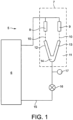
- the invention provides a CIJ printer 5 having a printer housing indicated generally by 6 and a printhead indicated in dotted outline at 7.
- the printer housing 6 contains an ink system including a system pump, printer drive and control electronics, and ink and make-up reservoirs.
- ink is fed by the system pump, under pressure, to the printhead.
- the printhead includes first and second ink droplet generators 8 and 9, each of which, in the conventional manner, emits a jet of ink. Each jet is broken into a stream of droplets 10 by applying a vibration or perturbation to the jet.
- a gutter 11 is provided to capture unprinted ink droplets.
- the gutter comprises a first arm 12 positioned to receive unprinted drops from the first ink droplet generator 8, a second arm 13 positioned to receive unprinted droplets from the second ink droplet generator 9, and a collection chamber 14 in which ink from the arms 12 and 13 collects.
- a gutter line 15 leads from the collection chamber 14 to convey unprinted ink back to the ink reservoir in the printer housing 6. This is achieved by means of a vacuum pump 16.
- a pressure sensor 17 measures vacuum within the gutter line and therefore generates a control input for the printer control electronics.
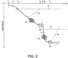
- the invention has been devised to provide a dual jet CIJ printer which, on start-up, can rapidly assume a ready-to-print status using only a single sensor to determine that ink from both of the first and second ink droplet generators 8 and 9 is being received in the gutter 11. In this particular embodiment, this is achieved by observing pressure characteristics of the ink and air flow through the gutter line 15 using the pressure sensor 17.
- the pump 16 is turned on and draws a partial vacuum in the gutter line 15.
- the vacuum level in the gutter line is relatively low, i.e., the pressure at the pressure sensor 17 is relatively high, albeit below atmospheric pressure, because at start-up the gutter line is clear and there is a free flow of air through the gutter line.
- the first ink droplet generator 8 is turned on, which causes a stream of ink droplets to be directed towards the arm 12 of the gutter 11. If the first ink droplet generator is operating correctly, the stream of ink droplets enters the arm 12 and the vacuum level in the gutter line starts to increase, i.e., the pressure at the pressure sensor 17 starts to decrease, because the ink droplets entering the arm 12 restrict the flow of air through the gutter line.
- the vacuum level in the gutter line continues to increase until the pressure at the pressure sensor falls at T3 below a first predetermined level (denoted by reference numeral 19) of, say, 20% below atmospheric pressure.
- the printer control electronics identify the pressure at the pressure sensor falling below the first predetermined level 19 as indicative that the first ink droplet generator is operating correctly and directing the stream of ink droplets into the arm 12 of the gutter.
- the printer control electronics monitor the rate of change of the vacuum level in the gutter line by storing pressure measurements from the pressure sensor in a rolling buffer, represented in Figure 2 by reference numeral 20.
- the printer control electronics identify the rate of change of the vacuum level rising and remaining for a predetermined time above a predetermined threshold level (the rate of change of the vacuum level initially being negative), the identification being denoted in Figure 2 by reference numeral 25, as indicative that the first droplet generator continues to operate correctly and that the pump 16 has reached a steady state of operation.
- the printer control electronics would have identified this behaviour as indicative that the first droplet generator 8 had ceased operating correctly and was no longer directing the stream of ink droplets into the arm 12 of the gutter. In this circumstance, which might arise if the nozzle of the first droplet generator 8 became partially blocked, the printer control electronics would shut down the printer.
- the second ink droplet generator 9 is turned on, which causes a stream of ink droplets to be directed towards the arm 13 of the gutter 11. If the second ink droplet generator is operating correctly, the stream of ink droplets enters the arm 13 and the vacuum level in the gutter line starts to increase again, i.e., the pressure at the pressure sensor 17 starts to decrease further, because the ink droplets entering the arm 13 further restrict the flow of air and ink droplets from the first ink droplet generator through the gutter line.
- the vacuum level in the gutter line continues to increase until at T6 the pressure at the pressure sensor falls below a second predetermined level (denoted by reference numeral 21) of, say, 20% below the steady state pressure identified at T5.
- the printer control electronics identify the pressure at the pressure sensor falling below the second predetermined level 21 as indicative that both the first and second ink droplet generators are operating correctly and directing their respective streams of ink droplets into the arms 12 and 13 of the gutter.
- the printer control electronics monitor the rate of change of the vacuum level in the gutter line by storing pressure measurements from the pressure sensor in the rolling buffer, represented in Figure 2 by reference numeral 22.
- the printer control electronics identify the rate of change of the vacuum level rising and remaining for the predetermined time above the predetermined threshold level, the identification being denoted in Figure 2 by reference numeral 26, as indicative that both the first and second ink droplet generators continue to operate correctly and that the pump has reached a steady state of operation.
- the printer control electronics would have identified this behaviour as indicative that at least one of the first and second droplet generators 8 and 9 had ceased operating correctly and was no longer directing its stream of ink droplets into the corresponding arm of the gutter. In this circumstance the printer control electronics would shut down the printer.
- the printer changes its status to ready-to-print.
- the present invention allows rapid priming of the printhead of a dual jet CIJ printer, and rapid identification of jet misalignment, using a single sensor.
Landscapes
- Ink Jet (AREA)
- Particle Formation And Scattering Control In Inkjet Printers (AREA)
Description
- This invention relates to a continuous inkjet printer that has first and second ink droplet generators and a common gutter arranged to receive ink droplets from the first and second ink droplet generators.
- Continuous inkjet ('CIJ') printers are widely used to place identification codes on products. Typically a CIJ printer includes a printer housing that contains a system for pressurising ink. Once pressurised, the ink is passed, via an ink feed line through a conduit, to a printhead. At the printhead the pressurised ink is passed through a nozzle of an ink droplet generator to form an ink jet. A vibration or perturbation is applied by the droplet generator to the inkjet causing the jet to break into a stream of droplets.
- The printer includes a charge electrode to charge selected droplets, and electrostatic deflection means to deflect the charged droplets away from their original trajectory and onto a substrate. By controlling the amount of charge that is placed on droplets, the trajectories of those droplets can be controlled to form a printed image.
- A CIJ printer is so termed because the printer forms a continuous stream of droplets irrespective of whether or not any particular droplet is to be used to print. The printer selects the drops to be used for printing by applying a charge to those drops, unprinted drops being allowed to continue, on the same trajectory as they were jetted from the nozzle, into a gutter. The unprinted drops collected in the gutter are returned from the printhead to the printer housing via a gutter line included in the same conduit as contains the pressurised ink feed line feeding ink to the printhead. Ink, together with entrained air, is generally returned to the printer housing under vacuum, the vacuum being generated by a pump in the gutter line.
- At the start-up of a CIJ printer, ink droplets are ejected from the droplet generator into the gutter whilst pressure (vacuum) within the gutter line is monitored. This allows any misalignment between the droplet generator and the gutter to be identified.
- Some embodiments of CIJ printer include first and second ink droplet generators aligned with a common gutter, an example of such a printer being described in UK Patent No.
GB 2 467 100 US 4 442 440 A . - Accordingly the invention provides a continuous inkjet printer having a printhead that includes first and second ink droplet generators, each operable to generate a stream of ink droplets, and a common gutter arranged to receive unprinted ink droplets from the first and second ink droplet generators, the printer further including control means configured to determine receipt into the common gutter of ink droplets from the first and second ink droplet generators, wherein the control means are operable to use a single sensor to determine receipt into the common gutter of ink droplets from one, both, or neither of the first and second ink droplet generators.
- Preferably the control means are configured to identify at least one characteristic of ink flow through a gutter line connected to the common gutter, the at least one characteristic being associated with receipt into the common gutter of ink from one, both, or neither of the first and second ink droplet generators.
- Preferably the control means are configured to identify the at least one characteristic of ink flow as the first and then the second ink droplet generator are brought into operation in sequence.
- Preferably the single sensor is a pressure sensor and the at least one characteristic comprises a pressure level and/or a rate of change of a pressure level in the gutter line connected to the common gutter.
- Preferably the control means are configured to determine receipt into the common gutter of ink droplets from the first ink droplet generator by identifying using the pressure sensor a first substantially stable pressure level in the gutter line, and to determine receipt into the common gutter of ink droplets from the first and second droplet generators by identifying using the pressure sensor a second substantially stable pressure level in the gutter line after identification of the first substantially stable pressure level in the gutter line.
- Preferably the control means are configured to report a fault and/or to shut down the printer in the event the first substantially stable pressure or the second substantially stable pressure is not identified.
- The invention will now be described, by way of example, with reference to the attached drawing figures, in which:
-
Figure 1 is a schematic diagram of a CIJ printer in accordance with the invention; and -
Figure 2 is a schematic plot of flow characteristics observed during the operation of such a CIJ printer. - Referring to
Figure 1 , the invention provides aCIJ printer 5 having a printer housing indicated generally by 6 and a printhead indicated in dotted outline at 7. In the conventional manner theprinter housing 6 contains an ink system including a system pump, printer drive and control electronics, and ink and make-up reservoirs. In the known manner ink is fed by the system pump, under pressure, to the printhead. In this particular embodiment the printhead includes first and secondink droplet generators 8 and 9, each of which, in the conventional manner, emits a jet of ink. Each jet is broken into a stream ofdroplets 10 by applying a vibration or perturbation to the jet. - A
gutter 11 is provided to capture unprinted ink droplets. In the form shown the gutter comprises afirst arm 12 positioned to receive unprinted drops from the firstink droplet generator 8, asecond arm 13 positioned to receive unprinted droplets from the second ink droplet generator 9, and acollection chamber 14 in which ink from thearms gutter line 15 leads from thecollection chamber 14 to convey unprinted ink back to the ink reservoir in theprinter housing 6. This is achieved by means of avacuum pump 16. A pressure sensor 17 measures vacuum within the gutter line and therefore generates a control input for the printer control electronics. - Turning now to
Figure 2 , the invention has been devised to provide a dual jet CIJ printer which, on start-up, can rapidly assume a ready-to-print status using only a single sensor to determine that ink from both of the first and secondink droplet generators 8 and 9 is being received in thegutter 11. In this particular embodiment, this is achieved by observing pressure characteristics of the ink and air flow through thegutter line 15 using the pressure sensor 17. - At T1 in
Figure 2 thepump 16 is turned on and draws a partial vacuum in thegutter line 15. The vacuum level in the gutter line is relatively low, i.e., the pressure at the pressure sensor 17 is relatively high, albeit below atmospheric pressure, because at start-up the gutter line is clear and there is a free flow of air through the gutter line. - At T2 the first
ink droplet generator 8 is turned on, which causes a stream of ink droplets to be directed towards thearm 12 of thegutter 11. If the first ink droplet generator is operating correctly, the stream of ink droplets enters thearm 12 and the vacuum level in the gutter line starts to increase, i.e., the pressure at the pressure sensor 17 starts to decrease, because the ink droplets entering thearm 12 restrict the flow of air through the gutter line. - The vacuum level in the gutter line continues to increase until the pressure at the pressure sensor falls at T3 below a first predetermined level (denoted by reference numeral 19) of, say, 20% below atmospheric pressure. The printer control electronics identify the pressure at the pressure sensor falling below the first
predetermined level 19 as indicative that the first ink droplet generator is operating correctly and directing the stream of ink droplets into thearm 12 of the gutter. - Between T3 and T4 the vacuum level in the gutter line continues to increase. The printer control electronics monitor the rate of change of the vacuum level in the gutter line by storing pressure measurements from the pressure sensor in a rolling buffer, represented in
Figure 2 byreference numeral 20. - The printer control electronics identify the rate of change of the vacuum level rising and remaining for a predetermined time above a predetermined threshold level (the rate of change of the vacuum level initially being negative), the identification being denoted in
Figure 2 byreference numeral 25, as indicative that the first droplet generator continues to operate correctly and that thepump 16 has reached a steady state of operation. - Had the rate of change of the vacuum level become positive, or the pressure at the pressure sensor risen above the first
predetermined level 19, as illustrated by the broken line denoted byreference numeral 23 inFigure 2 , the printer control electronics would have identified this behaviour as indicative that thefirst droplet generator 8 had ceased operating correctly and was no longer directing the stream of ink droplets into thearm 12 of the gutter. In this circumstance, which might arise if the nozzle of thefirst droplet generator 8 became partially blocked, the printer control electronics would shut down the printer. - At T5, assuming that correct operation of the first
ink droplet generator 8 has been identified, the second ink droplet generator 9 is turned on, which causes a stream of ink droplets to be directed towards thearm 13 of thegutter 11. If the second ink droplet generator is operating correctly, the stream of ink droplets enters thearm 13 and the vacuum level in the gutter line starts to increase again, i.e., the pressure at the pressure sensor 17 starts to decrease further, because the ink droplets entering thearm 13 further restrict the flow of air and ink droplets from the first ink droplet generator through the gutter line. - The vacuum level in the gutter line continues to increase until at T6 the pressure at the pressure sensor falls below a second predetermined level (denoted by reference numeral 21) of, say, 20% below the steady state pressure identified at T5. The printer control electronics identify the pressure at the pressure sensor falling below the second
predetermined level 21 as indicative that both the first and second ink droplet generators are operating correctly and directing their respective streams of ink droplets into thearms - Between T6 and T7 the vacuum level in the gutter line continues to increase. The printer control electronics monitor the rate of change of the vacuum level in the gutter line by storing pressure measurements from the pressure sensor in the rolling buffer, represented in
Figure 2 byreference numeral 22. - The printer control electronics identify the rate of change of the vacuum level rising and remaining for the predetermined time above the predetermined threshold level, the identification being denoted in
Figure 2 byreference numeral 26, as indicative that both the first and second ink droplet generators continue to operate correctly and that the pump has reached a steady state of operation. - Had the rate of change of the vacuum level become positive, or the pressure at the pressure sensor risen above the second
predetermined level 21, as illustrated by the broken line denoted byreference numeral 24 inFigure 2 , the printer control electronics would have identified this behaviour as indicative that at least one of the first andsecond droplet generators 8 and 9 had ceased operating correctly and was no longer directing its stream of ink droplets into the corresponding arm of the gutter. In this circumstance the printer control electronics would shut down the printer. - At T7, assuming that correct operation of both ink droplet generators has been identified, the printer changes its status to ready-to-print.
- It will be appreciated that the present invention, at least in the case of the embodiment described, allows rapid priming of the printhead of a dual jet CIJ printer, and rapid identification of jet misalignment, using a single sensor.
Claims (6)
- A continuous inkjet printer (5) having a printhead (7) that includes first and second ink droplet generators (8, 9), each operable to generate a stream of ink droplets (10), and a common gutter (11) arranged to receive unprinted ink droplets from the first and second ink droplet generators (8, 9), the printer (5) further including control means configured to determine receipt into the common gutter (11) of ink droplets from the first and second ink droplet generators (8, 9), characterised in that the control means are operable to use a single sensor (17) to determine receipt into the common gutter (11) of ink droplets from one, both, and neither of the first and second ink droplet generators (8, 9).
- The continuous inkjet printer (5) according to claim 1, wherein the control means are configured to identify at least one characteristic of ink flow through a gutter line (15) connected to the common gutter (11), the at least one characteristic being associated with receipt into the common gutter (11) of ink from one, both, or neither of the first and second ink droplet generators (8, 9).
- The continuous inkjet printer (5) according to claim 2, wherein the control means are configured to identify the at least one characteristic of ink flow as the first (8) and then the second ink droplet generator (9) are brought into operation in sequence.
- The continuous inkjet printer (5) according to claim 2 or 3, wherein the single sensor (17) is a pressure sensor (17) and the at least one characteristic comprises a pressure level and/or a rate of change of a pressure level in the gutter line (15) connected to the common gutter (11).
- The continuous inkjet printer (5) according to claim 4, wherein the control means are configured to determine receipt into the common gutter (11) of ink droplets from the first ink droplet generator (8) by identifying using the pressure sensor (17) a first substantially stable pressure level (25) in the gutter line (15), and to determine receipt into the common gutter (11) of ink droplets from the first and second droplet generators (8, 9) by identifying using the pressure sensor (17) a second substantially stable pressure level (26) in the gutter line (15) after identification of the first substantially stable pressure level (25) in the gutter line (15).
- The continuous inkjet printer (5) according to claim 5, wherein the control means are configured to report a fault and/or to shut down the printer in the event the first substantially stable pressure (25) or the second substantially stable pressure (26) is not identified.
Applications Claiming Priority (2)
| Application Number | Priority Date | Filing Date | Title |
|---|---|---|---|
| GB1813503.8A GB2576503A (en) | 2018-08-20 | 2018-08-20 | Common gutter sensing |
| PCT/GB2019/000111 WO2020039154A1 (en) | 2018-08-20 | 2019-08-03 | Common gutter sensing |
Publications (2)
| Publication Number | Publication Date |
|---|---|
| EP3840955A1 EP3840955A1 (en) | 2021-06-30 |
| EP3840955B1 true EP3840955B1 (en) | 2023-05-10 |
Family
ID=63668215
Family Applications (1)
| Application Number | Title | Priority Date | Filing Date |
|---|---|---|---|
| EP19765297.7A Active EP3840955B1 (en) | 2018-08-20 | 2019-08-03 | Common gutter sensing |
Country Status (4)
| Country | Link |
|---|---|
| US (1) | US11623454B2 (en) |
| EP (1) | EP3840955B1 (en) |
| GB (1) | GB2576503A (en) |
| WO (1) | WO2020039154A1 (en) |
Family Cites Families (13)
| Publication number | Priority date | Publication date | Assignee | Title |
|---|---|---|---|---|
| JPS55158974A (en) * | 1979-05-26 | 1980-12-10 | Ricoh Co Ltd | Choking detector in ink jet printer and remover thereof |
| US4410895A (en) | 1981-10-26 | 1983-10-18 | Xerox Corporation | Ink jet sensor method and apparatus |
| US4442440A (en) * | 1982-04-05 | 1984-04-10 | Xerox Corporation | Ink jet gutter method and apparatus |
| JPS6083849A (en) * | 1983-10-14 | 1985-05-13 | Ricoh Co Ltd | Charge detection method for multi-nozzle inkjet recording device |
| JPS6179670A (en) * | 1984-09-28 | 1986-04-23 | Ricoh Co Ltd | Charge phase control method in charge amount controlled multi-nozzle inkjet recording device |
| JPS61206659A (en) * | 1985-03-11 | 1986-09-12 | Ricoh Co Ltd | inkjet printer |
| JPS6280053A (en) * | 1985-10-04 | 1987-04-13 | Ricoh Co Ltd | Multi-nozzle ink jet recorder |
| US4746929A (en) * | 1987-01-16 | 1988-05-24 | Xerox Corporation | Traveling wave droplet generator for an ink jet printer |
| GB2455775B (en) * | 2007-12-21 | 2012-07-18 | Linx Printing Tech | Inkjet printer and flow restriction system therefor |
| GB2467100B (en) | 2008-11-14 | 2012-10-10 | Domino Printing Sciences Plc | Improvements in or relating to continuous inkjet printers |
| GB2479751B (en) * | 2010-04-21 | 2015-10-07 | Domino Printing Sciences Plc | Improvements in or relating to continuous inkjet printers |
| JP2014065203A (en) * | 2012-09-26 | 2014-04-17 | Hitachi Industrial Equipment Systems Co Ltd | Inkjet recording device |
| US9975326B2 (en) * | 2014-06-05 | 2018-05-22 | Videojet Technologies Inc. | Continuous ink jet print head with zero adjustment embedded charging electrode |
-
2018
- 2018-08-20 GB GB1813503.8A patent/GB2576503A/en not_active Withdrawn
-
2019
- 2019-08-03 US US17/269,785 patent/US11623454B2/en active Active
- 2019-08-03 EP EP19765297.7A patent/EP3840955B1/en active Active
- 2019-08-03 WO PCT/GB2019/000111 patent/WO2020039154A1/en not_active Ceased
Also Published As
| Publication number | Publication date |
|---|---|
| GB201813503D0 (en) | 2018-10-03 |
| US20210237464A1 (en) | 2021-08-05 |
| US11623454B2 (en) | 2023-04-11 |
| EP3840955A1 (en) | 2021-06-30 |
| WO2020039154A1 (en) | 2020-02-27 |
| GB2576503A (en) | 2020-02-26 |
Similar Documents
| Publication | Publication Date | Title |
|---|---|---|
| EP3213182B1 (en) | Printhead data error detection and response | |
| US8336981B2 (en) | Determining a healthy fluid ejection nozzle | |
| US6969159B2 (en) | Ink drop detector configurations | |
| EP1886815A1 (en) | Print module, information processing device, print system, print unit, ink supply unit, print method, and program | |
| GB2479751A (en) | Ink blockage determination for multi-jet continuous inkjet printer | |
| EP3375613A2 (en) | Inkjet print apparatus and recovery method of inkjet print apparatus | |
| CN109649010B (en) | Inkjet printing system and method for monitoring ink pressure in a printhead | |
| US8360543B2 (en) | Liquid ejecting apparatus and ejection inspecting method | |
| US20040207676A1 (en) | Detection device for detecting ejection condition of nozzles | |
| US4612553A (en) | Method for operational status checks of an ink jet printer | |
| JP6441729B2 (en) | Ink jet recording apparatus and ink viscosity control method used therefor | |
| US4364055A (en) | Ink issuance direction check system in an ink jet system printer | |
| US8616673B2 (en) | Method of controlling print density | |
| US11623454B2 (en) | Common gutter sensing | |
| US6767088B2 (en) | Methods and systems for detecting and determining trajectories of ink droplets | |
| CN114312088A (en) | Method for printing multiple ink drops at high speed | |
| US10647114B2 (en) | Continuous inkjet printers | |
| JP2019181727A (en) | Ink jet recording device | |
| CN100572071C (en) | Threshold automatic adjustment system and method for phase adjustment | |
| EP0805040B1 (en) | Bubble flow detection | |
| WO2024014105A1 (en) | Inkjet printer, inkjet printer control method, and printing system | |
| US20180050535A1 (en) | Inkjet Recording Device | |
| US9475305B2 (en) | Liquid supply apparatus and liquid ejection apparatus with contactless detection of liquid remaining amount | |
| JP2023117915A (en) | Inkjet printer and method of controlling an inkjet printer | |
| US20080218562A1 (en) | Drop deflection selectable via jet steering |
Legal Events
| Date | Code | Title | Description |
|---|---|---|---|
| STAA | Information on the status of an ep patent application or granted ep patent |
Free format text: STATUS: UNKNOWN |
|
| STAA | Information on the status of an ep patent application or granted ep patent |
Free format text: STATUS: THE INTERNATIONAL PUBLICATION HAS BEEN MADE |
|
| PUAI | Public reference made under article 153(3) epc to a published international application that has entered the european phase |
Free format text: ORIGINAL CODE: 0009012 |
|
| STAA | Information on the status of an ep patent application or granted ep patent |
Free format text: STATUS: REQUEST FOR EXAMINATION WAS MADE |
|
| 17P | Request for examination filed |
Effective date: 20210317 |
|
| AK | Designated contracting states |
Kind code of ref document: A1 Designated state(s): AL AT BE BG CH CY CZ DE DK EE ES FI FR GB GR HR HU IE IS IT LI LT LU LV MC MK MT NL NO PL PT RO RS SE SI SK SM TR |
|
| DAV | Request for validation of the european patent (deleted) | ||
| DAX | Request for extension of the european patent (deleted) | ||
| GRAP | Despatch of communication of intention to grant a patent |
Free format text: ORIGINAL CODE: EPIDOSNIGR1 |
|
| STAA | Information on the status of an ep patent application or granted ep patent |
Free format text: STATUS: GRANT OF PATENT IS INTENDED |
|
| INTG | Intention to grant announced |
Effective date: 20221118 |
|
| GRAS | Grant fee paid |
Free format text: ORIGINAL CODE: EPIDOSNIGR3 |
|
| GRAA | (expected) grant |
Free format text: ORIGINAL CODE: 0009210 |
|
| STAA | Information on the status of an ep patent application or granted ep patent |
Free format text: STATUS: THE PATENT HAS BEEN GRANTED |
|
| AK | Designated contracting states |
Kind code of ref document: B1 Designated state(s): AL AT BE BG CH CY CZ DE DK EE ES FI FR GB GR HR HU IE IS IT LI LT LU LV MC MK MT NL NO PL PT RO RS SE SI SK SM TR |
|
| REG | Reference to a national code |
Ref country code: GB Ref legal event code: FG4D |
|
| REG | Reference to a national code |
Ref country code: AT Ref legal event code: REF Ref document number: 1566319 Country of ref document: AT Kind code of ref document: T Effective date: 20230515 Ref country code: CH Ref legal event code: EP |
|
| REG | Reference to a national code |
Ref country code: DE Ref legal event code: R096 Ref document number: 602019028792 Country of ref document: DE |
|
| REG | Reference to a national code |
Ref country code: IE Ref legal event code: FG4D |
|
| P01 | Opt-out of the competence of the unified patent court (upc) registered |
Effective date: 20230425 |
|
| REG | Reference to a national code |
Ref country code: LT Ref legal event code: MG9D |
|
| REG | Reference to a national code |
Ref country code: NL Ref legal event code: MP Effective date: 20230510 |
|
| REG | Reference to a national code |
Ref country code: AT Ref legal event code: MK05 Ref document number: 1566319 Country of ref document: AT Kind code of ref document: T Effective date: 20230510 |
|
| PG25 | Lapsed in a contracting state [announced via postgrant information from national office to epo] |
Ref country code: SE Free format text: LAPSE BECAUSE OF FAILURE TO SUBMIT A TRANSLATION OF THE DESCRIPTION OR TO PAY THE FEE WITHIN THE PRESCRIBED TIME-LIMIT Effective date: 20230510 Ref country code: PT Free format text: LAPSE BECAUSE OF FAILURE TO SUBMIT A TRANSLATION OF THE DESCRIPTION OR TO PAY THE FEE WITHIN THE PRESCRIBED TIME-LIMIT Effective date: 20230911 Ref country code: NO Free format text: LAPSE BECAUSE OF FAILURE TO SUBMIT A TRANSLATION OF THE DESCRIPTION OR TO PAY THE FEE WITHIN THE PRESCRIBED TIME-LIMIT Effective date: 20230810 Ref country code: NL Free format text: LAPSE BECAUSE OF FAILURE TO SUBMIT A TRANSLATION OF THE DESCRIPTION OR TO PAY THE FEE WITHIN THE PRESCRIBED TIME-LIMIT Effective date: 20230510 Ref country code: ES Free format text: LAPSE BECAUSE OF FAILURE TO SUBMIT A TRANSLATION OF THE DESCRIPTION OR TO PAY THE FEE WITHIN THE PRESCRIBED TIME-LIMIT Effective date: 20230510 Ref country code: AT Free format text: LAPSE BECAUSE OF FAILURE TO SUBMIT A TRANSLATION OF THE DESCRIPTION OR TO PAY THE FEE WITHIN THE PRESCRIBED TIME-LIMIT Effective date: 20230510 |
|
| PG25 | Lapsed in a contracting state [announced via postgrant information from national office to epo] |
Ref country code: RS Free format text: LAPSE BECAUSE OF FAILURE TO SUBMIT A TRANSLATION OF THE DESCRIPTION OR TO PAY THE FEE WITHIN THE PRESCRIBED TIME-LIMIT Effective date: 20230510 Ref country code: PL Free format text: LAPSE BECAUSE OF FAILURE TO SUBMIT A TRANSLATION OF THE DESCRIPTION OR TO PAY THE FEE WITHIN THE PRESCRIBED TIME-LIMIT Effective date: 20230510 Ref country code: LV Free format text: LAPSE BECAUSE OF FAILURE TO SUBMIT A TRANSLATION OF THE DESCRIPTION OR TO PAY THE FEE WITHIN THE PRESCRIBED TIME-LIMIT Effective date: 20230510 Ref country code: LT Free format text: LAPSE BECAUSE OF FAILURE TO SUBMIT A TRANSLATION OF THE DESCRIPTION OR TO PAY THE FEE WITHIN THE PRESCRIBED TIME-LIMIT Effective date: 20230510 Ref country code: IS Free format text: LAPSE BECAUSE OF FAILURE TO SUBMIT A TRANSLATION OF THE DESCRIPTION OR TO PAY THE FEE WITHIN THE PRESCRIBED TIME-LIMIT Effective date: 20230910 Ref country code: HR Free format text: LAPSE BECAUSE OF FAILURE TO SUBMIT A TRANSLATION OF THE DESCRIPTION OR TO PAY THE FEE WITHIN THE PRESCRIBED TIME-LIMIT Effective date: 20230510 Ref country code: GR Free format text: LAPSE BECAUSE OF FAILURE TO SUBMIT A TRANSLATION OF THE DESCRIPTION OR TO PAY THE FEE WITHIN THE PRESCRIBED TIME-LIMIT Effective date: 20230811 |
|
| PG25 | Lapsed in a contracting state [announced via postgrant information from national office to epo] |
Ref country code: FI Free format text: LAPSE BECAUSE OF FAILURE TO SUBMIT A TRANSLATION OF THE DESCRIPTION OR TO PAY THE FEE WITHIN THE PRESCRIBED TIME-LIMIT Effective date: 20230510 |
|
| PG25 | Lapsed in a contracting state [announced via postgrant information from national office to epo] |
Ref country code: SK Free format text: LAPSE BECAUSE OF FAILURE TO SUBMIT A TRANSLATION OF THE DESCRIPTION OR TO PAY THE FEE WITHIN THE PRESCRIBED TIME-LIMIT Effective date: 20230510 |
|
| PG25 | Lapsed in a contracting state [announced via postgrant information from national office to epo] |
Ref country code: SM Free format text: LAPSE BECAUSE OF FAILURE TO SUBMIT A TRANSLATION OF THE DESCRIPTION OR TO PAY THE FEE WITHIN THE PRESCRIBED TIME-LIMIT Effective date: 20230510 Ref country code: SK Free format text: LAPSE BECAUSE OF FAILURE TO SUBMIT A TRANSLATION OF THE DESCRIPTION OR TO PAY THE FEE WITHIN THE PRESCRIBED TIME-LIMIT Effective date: 20230510 Ref country code: RO Free format text: LAPSE BECAUSE OF FAILURE TO SUBMIT A TRANSLATION OF THE DESCRIPTION OR TO PAY THE FEE WITHIN THE PRESCRIBED TIME-LIMIT Effective date: 20230510 Ref country code: EE Free format text: LAPSE BECAUSE OF FAILURE TO SUBMIT A TRANSLATION OF THE DESCRIPTION OR TO PAY THE FEE WITHIN THE PRESCRIBED TIME-LIMIT Effective date: 20230510 Ref country code: DK Free format text: LAPSE BECAUSE OF FAILURE TO SUBMIT A TRANSLATION OF THE DESCRIPTION OR TO PAY THE FEE WITHIN THE PRESCRIBED TIME-LIMIT Effective date: 20230510 Ref country code: CZ Free format text: LAPSE BECAUSE OF FAILURE TO SUBMIT A TRANSLATION OF THE DESCRIPTION OR TO PAY THE FEE WITHIN THE PRESCRIBED TIME-LIMIT Effective date: 20230510 |
|
| REG | Reference to a national code |
Ref country code: DE Ref legal event code: R097 Ref document number: 602019028792 Country of ref document: DE |
|
| PG25 | Lapsed in a contracting state [announced via postgrant information from national office to epo] |
Ref country code: MC Free format text: LAPSE BECAUSE OF FAILURE TO SUBMIT A TRANSLATION OF THE DESCRIPTION OR TO PAY THE FEE WITHIN THE PRESCRIBED TIME-LIMIT Effective date: 20230510 |
|
| PLBE | No opposition filed within time limit |
Free format text: ORIGINAL CODE: 0009261 |
|
| STAA | Information on the status of an ep patent application or granted ep patent |
Free format text: STATUS: NO OPPOSITION FILED WITHIN TIME LIMIT |
|
| REG | Reference to a national code |
Ref country code: CH Ref legal event code: PL |
|
| PG25 | Lapsed in a contracting state [announced via postgrant information from national office to epo] |
Ref country code: MC Free format text: LAPSE BECAUSE OF FAILURE TO SUBMIT A TRANSLATION OF THE DESCRIPTION OR TO PAY THE FEE WITHIN THE PRESCRIBED TIME-LIMIT Effective date: 20230510 |
|
| PG25 | Lapsed in a contracting state [announced via postgrant information from national office to epo] |
Ref country code: LU Free format text: LAPSE BECAUSE OF NON-PAYMENT OF DUE FEES Effective date: 20230803 |
|
| 26N | No opposition filed |
Effective date: 20240213 |
|
| PG25 | Lapsed in a contracting state [announced via postgrant information from national office to epo] |
Ref country code: LU Free format text: LAPSE BECAUSE OF NON-PAYMENT OF DUE FEES Effective date: 20230803 Ref country code: CH Free format text: LAPSE BECAUSE OF NON-PAYMENT OF DUE FEES Effective date: 20230831 |
|
| PG25 | Lapsed in a contracting state [announced via postgrant information from national office to epo] |
Ref country code: SI Free format text: LAPSE BECAUSE OF FAILURE TO SUBMIT A TRANSLATION OF THE DESCRIPTION OR TO PAY THE FEE WITHIN THE PRESCRIBED TIME-LIMIT Effective date: 20230510 |
|
| REG | Reference to a national code |
Ref country code: BE Ref legal event code: MM Effective date: 20230831 |
|
| REG | Reference to a national code |
Ref country code: IE Ref legal event code: MM4A |
|
| PG25 | Lapsed in a contracting state [announced via postgrant information from national office to epo] |
Ref country code: SI Free format text: LAPSE BECAUSE OF FAILURE TO SUBMIT A TRANSLATION OF THE DESCRIPTION OR TO PAY THE FEE WITHIN THE PRESCRIBED TIME-LIMIT Effective date: 20230510 |
|
| PG25 | Lapsed in a contracting state [announced via postgrant information from national office to epo] |
Ref country code: IE Free format text: LAPSE BECAUSE OF NON-PAYMENT OF DUE FEES Effective date: 20230803 |
|
| PG25 | Lapsed in a contracting state [announced via postgrant information from national office to epo] |
Ref country code: IE Free format text: LAPSE BECAUSE OF NON-PAYMENT OF DUE FEES Effective date: 20230803 |
|
| PG25 | Lapsed in a contracting state [announced via postgrant information from national office to epo] |
Ref country code: BE Free format text: LAPSE BECAUSE OF NON-PAYMENT OF DUE FEES Effective date: 20230831 |
|
| PG25 | Lapsed in a contracting state [announced via postgrant information from national office to epo] |
Ref country code: BG Free format text: LAPSE BECAUSE OF FAILURE TO SUBMIT A TRANSLATION OF THE DESCRIPTION OR TO PAY THE FEE WITHIN THE PRESCRIBED TIME-LIMIT Effective date: 20230510 |
|
| PG25 | Lapsed in a contracting state [announced via postgrant information from national office to epo] |
Ref country code: BG Free format text: LAPSE BECAUSE OF FAILURE TO SUBMIT A TRANSLATION OF THE DESCRIPTION OR TO PAY THE FEE WITHIN THE PRESCRIBED TIME-LIMIT Effective date: 20230510 |
|
| PG25 | Lapsed in a contracting state [announced via postgrant information from national office to epo] |
Ref country code: CY Free format text: LAPSE BECAUSE OF FAILURE TO SUBMIT A TRANSLATION OF THE DESCRIPTION OR TO PAY THE FEE WITHIN THE PRESCRIBED TIME-LIMIT; INVALID AB INITIO Effective date: 20190803 |
|
| PG25 | Lapsed in a contracting state [announced via postgrant information from national office to epo] |
Ref country code: HU Free format text: LAPSE BECAUSE OF FAILURE TO SUBMIT A TRANSLATION OF THE DESCRIPTION OR TO PAY THE FEE WITHIN THE PRESCRIBED TIME-LIMIT; INVALID AB INITIO Effective date: 20190803 |
|
| PGFP | Annual fee paid to national office [announced via postgrant information from national office to epo] |
Ref country code: DE Payment date: 20250819 Year of fee payment: 7 |
|
| PGFP | Annual fee paid to national office [announced via postgrant information from national office to epo] |
Ref country code: IT Payment date: 20250821 Year of fee payment: 7 |
|
| PGFP | Annual fee paid to national office [announced via postgrant information from national office to epo] |
Ref country code: GB Payment date: 20250818 Year of fee payment: 7 |
|
| PGFP | Annual fee paid to national office [announced via postgrant information from national office to epo] |
Ref country code: FR Payment date: 20250818 Year of fee payment: 7 |
|
| PG25 | Lapsed in a contracting state [announced via postgrant information from national office to epo] |
Ref country code: TR Free format text: LAPSE BECAUSE OF FAILURE TO SUBMIT A TRANSLATION OF THE DESCRIPTION OR TO PAY THE FEE WITHIN THE PRESCRIBED TIME-LIMIT Effective date: 20230510 |