EP3840823B1 - Generating tumor treating fields (ttfields) with high uniformity throughout the brain - Google Patents
Generating tumor treating fields (ttfields) with high uniformity throughout the brain Download PDFInfo
- Publication number
- EP3840823B1 EP3840823B1 EP19797802.6A EP19797802A EP3840823B1 EP 3840823 B1 EP3840823 B1 EP 3840823B1 EP 19797802 A EP19797802 A EP 19797802A EP 3840823 B1 EP3840823 B1 EP 3840823B1
- Authority
- EP
- European Patent Office
- Prior art keywords
- electrode elements
- capacitively
- person
- brain
- coupled electrode
- Prior art date
- Legal status (The legal status is an assumption and is not a legal conclusion. Google has not performed a legal analysis and makes no representation as to the accuracy of the status listed.)
- Active
Links
Images

Classifications
-
- A—HUMAN NECESSITIES
- A61—MEDICAL OR VETERINARY SCIENCE; HYGIENE
- A61N—ELECTROTHERAPY; MAGNETOTHERAPY; RADIATION THERAPY; ULTRASOUND THERAPY
- A61N1/00—Electrotherapy; Circuits therefor
- A61N1/02—Details
- A61N1/04—Electrodes
- A61N1/0404—Electrodes for external use
- A61N1/0408—Use-related aspects
-
- A—HUMAN NECESSITIES
- A61—MEDICAL OR VETERINARY SCIENCE; HYGIENE
- A61N—ELECTROTHERAPY; MAGNETOTHERAPY; RADIATION THERAPY; ULTRASOUND THERAPY
- A61N1/00—Electrotherapy; Circuits therefor
- A61N1/02—Details
- A61N1/04—Electrodes
- A61N1/0404—Electrodes for external use
- A61N1/0408—Use-related aspects
- A61N1/0456—Specially adapted for transcutaneous electrical nerve stimulation [TENS]
-
- A—HUMAN NECESSITIES
- A61—MEDICAL OR VETERINARY SCIENCE; HYGIENE
- A61N—ELECTROTHERAPY; MAGNETOTHERAPY; RADIATION THERAPY; ULTRASOUND THERAPY
- A61N1/00—Electrotherapy; Circuits therefor
- A61N1/02—Details
- A61N1/04—Electrodes
- A61N1/0404—Electrodes for external use
- A61N1/0472—Structure-related aspects
- A61N1/0476—Array electrodes (including any electrode arrangement with more than one electrode for at least one of the polarities)
-
- A—HUMAN NECESSITIES
- A61—MEDICAL OR VETERINARY SCIENCE; HYGIENE
- A61N—ELECTROTHERAPY; MAGNETOTHERAPY; RADIATION THERAPY; ULTRASOUND THERAPY
- A61N1/00—Electrotherapy; Circuits therefor
- A61N1/02—Details
- A61N1/04—Electrodes
- A61N1/0404—Electrodes for external use
- A61N1/0472—Structure-related aspects
- A61N1/0492—Patch electrodes
-
- A—HUMAN NECESSITIES
- A61—MEDICAL OR VETERINARY SCIENCE; HYGIENE
- A61N—ELECTROTHERAPY; MAGNETOTHERAPY; RADIATION THERAPY; ULTRASOUND THERAPY
- A61N1/00—Electrotherapy; Circuits therefor
- A61N1/02—Details
- A61N1/08—Arrangements or circuits for monitoring, protecting, controlling or indicating
-
- A—HUMAN NECESSITIES
- A61—MEDICAL OR VETERINARY SCIENCE; HYGIENE
- A61N—ELECTROTHERAPY; MAGNETOTHERAPY; RADIATION THERAPY; ULTRASOUND THERAPY
- A61N1/00—Electrotherapy; Circuits therefor
- A61N1/18—Applying electric currents by contact electrodes
- A61N1/32—Applying electric currents by contact electrodes alternating or intermittent currents
- A61N1/36—Applying electric currents by contact electrodes alternating or intermittent currents for stimulation
-
- A—HUMAN NECESSITIES
- A61—MEDICAL OR VETERINARY SCIENCE; HYGIENE
- A61N—ELECTROTHERAPY; MAGNETOTHERAPY; RADIATION THERAPY; ULTRASOUND THERAPY
- A61N1/00—Electrotherapy; Circuits therefor
- A61N1/18—Applying electric currents by contact electrodes
- A61N1/32—Applying electric currents by contact electrodes alternating or intermittent currents
- A61N1/36—Applying electric currents by contact electrodes alternating or intermittent currents for stimulation
- A61N1/36002—Cancer treatment, e.g. tumour
-
- A—HUMAN NECESSITIES
- A61—MEDICAL OR VETERINARY SCIENCE; HYGIENE
- A61N—ELECTROTHERAPY; MAGNETOTHERAPY; RADIATION THERAPY; ULTRASOUND THERAPY
- A61N1/00—Electrotherapy; Circuits therefor
- A61N1/18—Applying electric currents by contact electrodes
- A61N1/32—Applying electric currents by contact electrodes alternating or intermittent currents
- A61N1/36—Applying electric currents by contact electrodes alternating or intermittent currents for stimulation
- A61N1/36014—External stimulators, e.g. with patch electrodes
-
- A—HUMAN NECESSITIES
- A61—MEDICAL OR VETERINARY SCIENCE; HYGIENE
- A61N—ELECTROTHERAPY; MAGNETOTHERAPY; RADIATION THERAPY; ULTRASOUND THERAPY
- A61N1/00—Electrotherapy; Circuits therefor
- A61N1/18—Applying electric currents by contact electrodes
- A61N1/32—Applying electric currents by contact electrodes alternating or intermittent currents
- A61N1/36—Applying electric currents by contact electrodes alternating or intermittent currents for stimulation
- A61N1/36014—External stimulators, e.g. with patch electrodes
- A61N1/36025—External stimulators, e.g. with patch electrodes for treating a mental or cerebral condition
-
- A—HUMAN NECESSITIES
- A61—MEDICAL OR VETERINARY SCIENCE; HYGIENE
- A61N—ELECTROTHERAPY; MAGNETOTHERAPY; RADIATION THERAPY; ULTRASOUND THERAPY
- A61N1/00—Electrotherapy; Circuits therefor
- A61N1/18—Applying electric currents by contact electrodes
- A61N1/32—Applying electric currents by contact electrodes alternating or intermittent currents
- A61N1/36—Applying electric currents by contact electrodes alternating or intermittent currents for stimulation
- A61N1/36014—External stimulators, e.g. with patch electrodes
- A61N1/3603—Control systems
-
- A—HUMAN NECESSITIES
- A61—MEDICAL OR VETERINARY SCIENCE; HYGIENE
- A61N—ELECTROTHERAPY; MAGNETOTHERAPY; RADIATION THERAPY; ULTRASOUND THERAPY
- A61N1/00—Electrotherapy; Circuits therefor
- A61N1/40—Applying electric fields by inductive or capacitive coupling ; Applying radio-frequency signals
-
- G—PHYSICS
- G16—INFORMATION AND COMMUNICATION TECHNOLOGY [ICT] SPECIALLY ADAPTED FOR SPECIFIC APPLICATION FIELDS
- G16H—HEALTHCARE INFORMATICS, i.e. INFORMATION AND COMMUNICATION TECHNOLOGY [ICT] SPECIALLY ADAPTED FOR THE HANDLING OR PROCESSING OF MEDICAL OR HEALTHCARE DATA
- G16H20/00—ICT specially adapted for therapies or health-improving plans, e.g. for handling prescriptions, for steering therapy or for monitoring patient compliance
- G16H20/40—ICT specially adapted for therapies or health-improving plans, e.g. for handling prescriptions, for steering therapy or for monitoring patient compliance relating to mechanical, radiation or invasive therapies, e.g. surgery, laser therapy, dialysis or acupuncture
-
- G—PHYSICS
- G16—INFORMATION AND COMMUNICATION TECHNOLOGY [ICT] SPECIALLY ADAPTED FOR SPECIFIC APPLICATION FIELDS
- G16H—HEALTHCARE INFORMATICS, i.e. INFORMATION AND COMMUNICATION TECHNOLOGY [ICT] SPECIALLY ADAPTED FOR THE HANDLING OR PROCESSING OF MEDICAL OR HEALTHCARE DATA
- G16H40/00—ICT specially adapted for the management or administration of healthcare resources or facilities; ICT specially adapted for the management or operation of medical equipment or devices
- G16H40/60—ICT specially adapted for the management or administration of healthcare resources or facilities; ICT specially adapted for the management or operation of medical equipment or devices for the operation of medical equipment or devices
- G16H40/63—ICT specially adapted for the management or administration of healthcare resources or facilities; ICT specially adapted for the management or operation of medical equipment or devices for the operation of medical equipment or devices for local operation
-
- G—PHYSICS
- G16—INFORMATION AND COMMUNICATION TECHNOLOGY [ICT] SPECIALLY ADAPTED FOR SPECIFIC APPLICATION FIELDS
- G16H—HEALTHCARE INFORMATICS, i.e. INFORMATION AND COMMUNICATION TECHNOLOGY [ICT] SPECIALLY ADAPTED FOR THE HANDLING OR PROCESSING OF MEDICAL OR HEALTHCARE DATA
- G16H50/00—ICT specially adapted for medical diagnosis, medical simulation or medical data mining; ICT specially adapted for detecting, monitoring or modelling epidemics or pandemics
- G16H50/50—ICT specially adapted for medical diagnosis, medical simulation or medical data mining; ICT specially adapted for detecting, monitoring or modelling epidemics or pandemics for simulation or modelling of medical disorders
Definitions
- TTFields are low intensity (e.g., 1-4 V/cm) alternating electric fields within the intermediate frequency range (e.g., 100-300 kHz), which may be used, for example, to treat tumors as described in US Patent 7,565,205 and Int. Pub. WO 2018057953 .
- TTFields therapy is an approved mono-treatment for recurrent glioblastoma (GBM), and an approved combination therapy with chemotherapy for newly diagnosed GBM patients.
- the alternating electric fields are induced non-invasively by transducer arrays (i.e., arrays of capacitively coupled electrodes) placed directly on the patient's head (e.g., using the Novocure Optune ® system), and applying AC voltages between the transducer arrays.
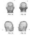
- the TTFields are delivered to patients via four transducer arrays 11-14 that are placed on the patient's skin in close proximity to a tumor (e.g., as depicted in FIGS. 1A-1D for a person with glioblastoma).
- the transducer arrays 11-14 are arranged in two pairs, and each transducer array is connected via a cable to an AC signal generator.
- the AC signal generator (a) sends an AC current through one pair of arrays 11, 12 during a first period of time, which induces an electric field with a first direction through the tumor; then (b) sends an AC current through the other pair of arrays 13, 14 during a second period of time, which induces an electric field with a second direction through the tumor; then repeats steps (a) and (b) for the duration of the treatment.
- One aspect of the invention is directed to an apparatus according to claim 1.
- TTFields can be used to treat and prevent metastases, as described in US patent 7,599,746 .
- this application discloses a variety of configurations for arranging the transducer arrays on a person's head to impose TTFields in the brain at field strengths that are as uniform as possible throughout the entire brain (including the infratentorial regions of the brain).
- FIGS. 1A-1D depict the conventional layout for positioning transducer arrays on a person's head for treating glioblastoma using TTFields.
- the AC signal generator first applies an AC voltage across the front/back pair of transducer arrays 11, 12, then applies an AC voltage across the right/left pair of transducer arrays 13, 14, and then repeats that two-step sequence for the duration of the treatment.
- the uniformity of field intensity for this conventional layout is relatively low.
- the field strengths are quite low in the infratentorial regions of the brain.
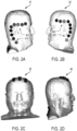
- FIGS 2A-2D depict a set of improved layouts for positioning transducer arrays on a person's head for preventing metastases using TTFields. More specifically, FIG. 2A shows that the first set of electrode elements 41 is affixed to a right side of the person's head. The first set of electrode elements 41 has an upper section 41H positioned above (i.e., superior to) the external opening of the person's right ear canal with an orientation that is predominantly horizontal, and a rear section 41V positioned behind the external opening of the person's right ear canal with an orientation that is predominantly vertical.
- FIG. 2B shows that the second set of electrode elements 42 is affixed to a left side of the person's head.
- the second set of electrode elements has an upper section 42H positioned above the external opening of the person's left ear canal with an orientation that is predominantly horizontal, and a rear section 42V positioned behind the external opening of the person's left ear canal with an orientation that is predominantly vertical.
- FIGS. 2C and 2D show that the third set of electrode elements 43 is affixed to the person's head with its centroid positioned on top of the person's head; and
- FIG. 2D shows that the fourth set of electrode elements 44 is affixed to the back of the person's neck with its centroid positioned below the person's C2 vertebra and above the person's C7 vertebra.
- the AC signal generator first applies an AC voltage across the first and second sets of electrode elements 41, 42, then applies an AC voltage across the third and fourth sets of electrode elements 43, 44, and then repeats that two-step sequence for the duration of the treatment.
- the uniformity of field intensity for this alternative layout is also significantly higher than in the conventional FIG. 1 layout.
- the upper section 41H of the first set of electrode elements includes at least three capacitively coupled electrode elements
- the rear section 41V of the first set of electrode elements includes at least three capacitively coupled electrode elements
- the upper section 42H of the second set of electrode elements includes at least three capacitively coupled electrode elements
- the rear section 42V of the second set of electrode elements includes at least three capacitively coupled electrode elements.
- Each of those sections 41H, 41V, 42H, 42V can include a different number of electrode elements (e.g., between 1 and 8).
- the upper section of each of the first and second sets of electrode elements (a) has a length of at least 6 cm, (b) is positioned less than 6 cm above the external opening of the respective ear canal, (c) has a front end positioned at least 1 cm in front of the external opening of the respective ear canal, and (d) has a rear end positioned at least 1 cm behind the external opening of the respective ear canal.
- the rear section of each of the first and second sets of electrode elements (a) has a length of at least 6 cm, (b) is positioned less than 6 cm behind the external opening of the respective ear canal, (c) has an upper end positioned at least 1 cm above the external opening of the respective ear canal, and (d) has a rear end positioned at least 3 cm below the external opening of the respective ear canal.
- the third set of electrode elements is affixed with its centroid positioned between 1 and 3 cm anterior to a vertex of the person's head.
- the fourth set of electrode elements is affixed with its centroid positioned below the person's C3 vertebra and above the person's C6 vertebra.
- FIG. 3 depicts a block diagram of a system that includes an AC voltage generator 50 that may be used to apply the AC voltage across the first and second sets of electrode elements (41/42 in FIG. 2 ) and across the third and fourth sets of electrode elements (43/44 in FIG. 2 ) in an alternating sequence as described above in connection with FIG. 2 above.
- an AC voltage generator 50 that may be used to apply the AC voltage across the first and second sets of electrode elements (41/42 in FIG. 2 ) and across the third and fourth sets of electrode elements (43/44 in FIG. 2 ) in an alternating sequence as described above in connection with FIG. 2 above.
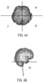
- FIGS. 4A-4B the infra-tentorial areas "in” (including the cerebellum and brain stem), and four compartments for the upper brain - front-right ⁇ , front-left ⁇ , rear-left ⁇ , and rear-right ⁇ .
- the boundaries between these regions of the brain are depicted in FIGS. 4A-4B .
- the field intensity was calculated for each voxel in each of the five compartments using finite element simulation. For each compartment the mean and median field intensities of all voxels in the compartment were calculated. Data was taken only for grey and white matter cells.
- ⁇ ⁇ T MEAN T
- SD stands for standard deviation
- ⁇ i is the mean of each compartment
- ⁇ , ⁇ , ⁇ and ⁇ are the cerebral compartments (see FIG. 4A ); and "in” is the cerebellum / brain stem compartment (see FIG. 4B ).
- FIGS. 1A/1B 1C/1D 2A/2B 2C/2D Electrodes 11/12 13/14 41/42 43/44 ⁇ [%] 29.38* 29.38 15.55 15.48 *The value for the FIGS. 1A-1B layout was estimated.
- the two best layouts for positioning the transducer arrays to obtain the highest uniformity throughout the brain are the layouts 43/44 (depicted in FIGS. 2C/2D ); and the layouts 41/42 (depicted in FIGS. 2A/2B ).
- the uniformity of the field created throughout the brain was evaluated by using finite element simulation to calculate the field strength at each voxel in the brain in the following two situations: (a) when an AC voltage is applied across the first and second sets of electrode elements (11/12, and 41/42, in FIGS. 1 , and 2 , respectively), and (b) when an AC voltage is applied across the third and fourth sets of electrode elements (13/14, and 43/44, in FIGS. 1 , and 2 , respectively). Then, for each voxel in the brain, the field strength result for situation (a) and the field strength result for situation (b) were averaged.
- ⁇ was calculated using the same three equations that were used to calculate ⁇ described above in connection with Table 1. Except this time, instead of using a single field strength for each voxel in the brain as the input to the equations, an average of two field strengths for each voxel in the brain was used as the input to the equations.
- each set of electrode elements is configured as a 3 x 3 array of individual electrode element discs.
- the centroid of the respective set will coincide with the center of the center disc.
- each set of electrode elements may include a different number of electrode elements.
- a given set of electrode elements may be configured as a 2 x 2 array of individual electrode element discs. In this situation, the centroid could be in a region that is located between all four disks.
- a given set of electrode elements may include only a single electrode element disc (which may be any suitable shape including but not limited to round and rectangular). In this situation, the centroid would coincide with the center of that single electrode element.
- all four sets of electrode elements are preferably capacitively coupled to the person's body.
- the following steps are repeated in an alternating sequence: (a) applying an alternating voltage between the first set of electrode elements and the second set of electrode elements, and (b) applying an alternating voltage between the third set of electrode elements and the fourth set of electrode elements.
- the frequency of these alternating voltages is between 100 kHz and 300 kHz.
- Tables 1-4 were obtained by simulating the electric fields that are obtained when each of the four sets of electrode elements was positioned as depicted in FIG. 2 . Note, however, that the positions of each set of electrode elements may be varied from the exact locations depicted in those figures, as long as the movement is small enough so that the respective anatomic description above remains unchanged.
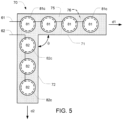
- FIG. 5 depicts an apparatus that may be used to implement either the first set of electrode elements 41 that is affixed to the right side of the person's head (shown in FIG. 2A ) or the second set of electrode elements 42 that is affixed to the left side of the person's head (shown in FIG. 2B ).
- This apparatus is used for applying an alternating electric field to a person's brain, and it comprises a flexible backing 70 having an outer side 76 (hidden in FIG. 5 ) and an inner side 75.
- the flexible backing 70 is configured for affixation to a side of the person's head with the inner side 75 facing the person's head.
- Suitable materials for the flexible backing include cloth, foam, and flexible plastic (e.g., similar to corresponding materials used in bandages).
- the flexible backing has a first arm 71 with a length of at least 6 cm in a first direction d1 and a second arm with a length of at least 6 cm in a second direction d2.
- a first plurality of capacitively coupled electrode elements 81 is positioned on the inner side 75 of the first arm 71 of the flexible backing 70, and each of the first plurality of capacitively coupled electrode elements 81 has a conductive plate 81c with a dielectric layer disposed thereon that faces inward.
- a second plurality of capacitively coupled electrode elements 82 is positioned on the inner side 75 of the second arm 72 of the flexible backing 70, and each of the second plurality of capacitively coupled electrode elements 82 has a conductive plate 82c with a dielectric layer disposed thereon that faces inward.
- the electrode elements 81, 82 may be similar to the conventional electrode elements used in the Novocure Optune ® system.
- temperature sensors e.g., thermistors
- a first set of conductors 61 connects to the conductive plates 81c of each of the first plurality of capacitively coupled electrode elements 81 in parallel, and a second set of conductors 62 connects to the conductive plates 82c of each of the second plurality of capacitively coupled electrode elements 82 in parallel.
- the conductors 62 may be implemented using, for example, discrete wiring or using traces on a flex circuit.
- a layer of adhesive (indicated by the dotted pattern) is positioned on the inner side 75 of the flexible backing 70, and this adhesive is configured to hold portions of the flexible backing 70 that are not covered by any of the electrode elements 81, 82 against the person's head.
- the first plurality of electrode elements 81 has four electrode elements and the second plurality of electrode elements 82 has three electrode elements.
- the number of electrode elements in each of the first and second pluralities of electrode elements can vary (e.g., between 2 and 10).
- the angle ⁇ between the first direction d1 and the second direction d2 is 90°.
- that angle ⁇ can be between 80° and 100°, or between 65° and 115°.
- the apparatus is suited for use as the second set of electrodes 42 that is positioned next to the left ear in FIG. 2B , with the first and second pluralities of electrode elements 81, 82 in FIG. 5 corresponding to the upper/horizontal arm 42H and the rear/vertical arm 42V, respectively, in FIG. 2B .
- the backing 70 is rotated clockwise by 90° with respect to the orientation shown in FIG. 5
- the same apparatus would then be suited for use as the first set of electrodes 41 that is positioned next to the right ear in FIG. 2A . More specifically, after a 90° clockwise rotation, the first plurality of electrode elements 81 in FIG. 5 would correspond to the rear/vertical arm 41V in FIG. 2A , and the second plurality of electrode elements 82 in FIG. 5 would correspond to the upper/horizontal arm 41H in FIG. 2A .
Landscapes
- Health & Medical Sciences (AREA)
- Engineering & Computer Science (AREA)
- Public Health (AREA)
- Biomedical Technology (AREA)
- General Health & Medical Sciences (AREA)
- Life Sciences & Earth Sciences (AREA)
- Nuclear Medicine, Radiotherapy & Molecular Imaging (AREA)
- Radiology & Medical Imaging (AREA)
- Animal Behavior & Ethology (AREA)
- Veterinary Medicine (AREA)
- Medical Informatics (AREA)
- Epidemiology (AREA)
- Primary Health Care (AREA)
- Heart & Thoracic Surgery (AREA)
- Neurology (AREA)
- Biophysics (AREA)
- Hospice & Palliative Care (AREA)
- Oncology (AREA)
- Databases & Information Systems (AREA)
- Urology & Nephrology (AREA)
- General Business, Economics & Management (AREA)
- Pathology (AREA)
- Business, Economics & Management (AREA)
- Data Mining & Analysis (AREA)
- Surgery (AREA)
- Child & Adolescent Psychology (AREA)
- Developmental Disabilities (AREA)
- Psychiatry (AREA)
- Psychology (AREA)
- Social Psychology (AREA)
- Electrotherapy Devices (AREA)
Description
- TTFields are low intensity (e.g., 1-4 V/cm) alternating electric fields within the intermediate frequency range (e.g., 100-300 kHz), which may be used, for example, to treat tumors as described in
US Patent 7,565,205 and Int.Pub. WO 2018057953 . TTFields therapy is an approved mono-treatment for recurrent glioblastoma (GBM), and an approved combination therapy with chemotherapy for newly diagnosed GBM patients. The alternating electric fields are induced non-invasively by transducer arrays (i.e., arrays of capacitively coupled electrodes) placed directly on the patient's head (e.g., using the Novocure Optune® system), and applying AC voltages between the transducer arrays. - For treating glioblastoma, the TTFields are delivered to patients via four transducer arrays 11-14 that are placed on the patient's skin in close proximity to a tumor (e.g., as depicted in
FIGS. 1A-1D for a person with glioblastoma). The transducer arrays 11-14 are arranged in two pairs, and each transducer array is connected via a cable to an AC signal generator. The AC signal generator (a) sends an AC current through one pair ofarrays arrays - In the context of glioblastoma, conventional solutions (e.g., NovoTAL software from Novocure) are available for determining where the transducer arrays 11-14 should be placed on a subject's head in order to maximize the field strength within the tumor. But because the prior art solutions are only concerned with the field distribution within the tumor, none of the prior art solutions addressed the uniformity of the electric field in other regions of the brain.
- One aspect of the invention is directed to an apparatus according to
claim 1. - Embodiments of the invention are disclosed in the dependent claims.
-
-
FIGS. 1A-1D depict the conventional layout for positioning transducer arrays on a person's head for treating glioblastoma using TTFields. -
FIGS. 2A-2D depict a set of improved layouts for positioning transducer arrays on a person's head for preventing metastases using TTFields. -
FIG. 3 depicts a block diagram of a system that may be used to apply the AC voltage across the sets of electrode elements depicted inFIG. 2 . -
FIGS. 4A and 4B depict how the brain is divided into five distinct regions α, β, γ, δ, and in. -
FIG. 5 depicts an apparatus that may be used for each of the sets of electrode elements shown inFIGS. 2A and 2B . - Various embodiments are described in detail below with reference to the accompanying drawings, wherein like reference numerals represent like elements.
- Many types of cancer (e.g., lung, breast, colon, kidney and melanoma) can metastasize to the brain. TTFields can be used to treat and prevent metastases, as described in
US patent 7,599,746 . - Because one never knows in advance the exact location within the brain that a metastasis may appear, a good way to prevent or treat metastases is to treat as much of the brain as possible with TTFields. Keeping the field strength as uniform as possible within the entire brain can maximize the percentage of the brain that receives a field strength large enough to prevent or treat the metastases, while preventing the transducer arrays from getting too hot and also conserving battery power. Consistent with these objectives, this application discloses a variety of configurations for arranging the transducer arrays on a person's head to impose TTFields in the brain at field strengths that are as uniform as possible throughout the entire brain (including the infratentorial regions of the brain).
-
FIGS. 1A-1D depict the conventional layout for positioning transducer arrays on a person's head for treating glioblastoma using TTFields. With this layout, the AC signal generator first applies an AC voltage across the front/back pair oftransducer arrays transducer arrays -
FIGS 2A-2D depict a set of improved layouts for positioning transducer arrays on a person's head for preventing metastases using TTFields. More specifically,FIG. 2A shows that the first set ofelectrode elements 41 is affixed to a right side of the person's head. The first set ofelectrode elements 41 has anupper section 41H positioned above (i.e., superior to) the external opening of the person's right ear canal with an orientation that is predominantly horizontal, and arear section 41V positioned behind the external opening of the person's right ear canal with an orientation that is predominantly vertical.FIG. 2B shows that the second set ofelectrode elements 42 is affixed to a left side of the person's head. The second set of electrode elements has anupper section 42H positioned above the external opening of the person's left ear canal with an orientation that is predominantly horizontal, and arear section 42V positioned behind the external opening of the person's left ear canal with an orientation that is predominantly vertical.FIGS. 2C and 2D show that the third set ofelectrode elements 43 is affixed to the person's head with its centroid positioned on top of the person's head; andFIG. 2D shows that the fourth set ofelectrode elements 44 is affixed to the back of the person's neck with its centroid positioned below the person's C2 vertebra and above the person's C7 vertebra. With this layout, the AC signal generator first applies an AC voltage across the first and second sets ofelectrode elements electrode elements FIG. 1 layout. - Optionally, in the
FIGS. 2A-2D layout, theupper section 41H of the first set of electrode elements includes at least three capacitively coupled electrode elements, therear section 41V of the first set of electrode elements includes at least three capacitively coupled electrode elements, theupper section 42H of the second set of electrode elements includes at least three capacitively coupled electrode elements, and therear section 42V of the second set of electrode elements includes at least three capacitively coupled electrode elements. Each of thosesections - Optionally, in the
FIGS. 2A-2D layout, the upper section of each of the first and second sets of electrode elements (a) has a length of at least 6 cm, (b) is positioned less than 6 cm above the external opening of the respective ear canal, (c) has a front end positioned at least 1 cm in front of the external opening of the respective ear canal, and (d) has a rear end positioned at least 1 cm behind the external opening of the respective ear canal. - Optionally, in the
FIGS. 2A-2D layout, the rear section of each of the first and second sets of electrode elements (a) has a length of at least 6 cm, (b) is positioned less than 6 cm behind the external opening of the respective ear canal, (c) has an upper end positioned at least 1 cm above the external opening of the respective ear canal, and (d) has a rear end positioned at least 3 cm below the external opening of the respective ear canal. - Optionally, in the
FIGS. 2A-2D layout, the third set of electrode elements is affixed with its centroid positioned between 1 and 3 cm anterior to a vertex of the person's head. - Optionally, in the
FIGS. 2A-2D layout, the fourth set of electrode elements is affixed with its centroid positioned below the person's C3 vertebra and above the person's C6 vertebra. -
FIG. 3 depicts a block diagram of a system that includes anAC voltage generator 50 that may be used to apply the AC voltage across the first and second sets of electrode elements (41/42 inFIG. 2 ) and across the third and fourth sets of electrode elements (43/44 inFIG. 2 ) in an alternating sequence as described above in connection withFIG. 2 above. - For each of the transducer array layouts depicted above, electric fields were simulated using a realistic human head model extending as far as the shoulders. In the simulations, transducer arrays with 9 capacitively coupled disc-shaped electrode elements, each having a diameter of 2 cm, were placed on the locations on the body described above in connection with
FIGS. 1 , and2 , and a constant current of 2A peak-to-peak with a 200 kHz frequency was applied to the outer surfaces of the disks. The simulations were performed using Sim4Life version 4 platform (ZMT-Zurich). To analyze the uniformity of the electric field, the brain was divided into five compartments as depicted inFIGS. 4A-4B : the infra-tentorial areas "in" (including the cerebellum and brain stem), and four compartments for the upper brain - front-right α, front-left β, rear-left γ, and rear-right δ. The boundaries between these regions of the brain are depicted inFIGS. 4A-4B . The field intensity was calculated for each voxel in each of the five compartments using finite element simulation. For each compartment the mean and median field intensities of all voxels in the compartment were calculated. Data was taken only for grey and white matter cells. - For each pair of transducer arrays in each of the layouts depicted above, ψ was defined as the standard deviation between the mean of the different compartments divided by the average of the different compartments, as follows.

- where σT = SD([µi]|i ∈ (α, β, γ, δ, in});
- and MEANT = mean([µi]|i ∈ (α, β, γ, δ, in})
- In these three equations, SD stands for standard deviation; µi is the mean of each compartment; α, β, γ and δ are the cerebral compartments (see
FIG. 4A ); and "in" is the cerebellum / brain stem compartment (seeFIG. 4B ). - The value of ψ obtained (in percent) for each individual pair of transducer arrays are presented in Table 1 below.
TABLE 1 FIGS. 1A/1B 1C/1D 2A/2B 2C/ 2D Electrodes 11/12 13/14 41/42 43/44 Ψ [%] 29.38* 29.38 15.55 15.48 *The value for the FIGS. 1A-1B layout was estimated. - Based on the results in Table 1, when only a single pair of transducer arrays is used to impose a field in a person's brain, the two best layouts for positioning the transducer arrays to obtain the highest uniformity throughout the brain are the
layouts 43/44 (depicted inFIGS. 2C/2D ); and thelayouts 41/42 (depicted inFIGS. 2A/2B ). - Next, for each set of the transducer array layouts depicted in
FIGS. 1 , and2 , the uniformity of the field created throughout the brain was evaluated by using finite element simulation to calculate the field strength at each voxel in the brain in the following two situations: (a) when an AC voltage is applied across the first and second sets of electrode elements (11/12, and 41/42, inFIGS. 1 , and2 , respectively), and (b) when an AC voltage is applied across the third and fourth sets of electrode elements (13/14, and 43/44, inFIGS. 1 , and2 , respectively). Then, for each voxel in the brain, the field strength result for situation (a) and the field strength result for situation (b) were averaged. - After obtaining the average field strength at each voxel in the brain, ψ was calculated using the same three equations that were used to calculate ψ described above in connection with Table 1. Except this time, instead of using a single field strength for each voxel in the brain as the input to the equations, an average of two field strengths for each voxel in the brain was used as the input to the equations.
- The value of ψ obtained for each set of four transducer arrays (in percent) are presented in Table 2 below. These values are based on the assumption that the field is applied between the first and second transducer arrays in any given set half the time, and between the third and fourth transducer arrays in the given set the other half of the time.
TABLE 2 FIGS. 1A-1D 2A-2D Electrode pairs that were averaged 11/12 and 13/14 41/42 and 43/44 Ψ [%] 29.38* 3.03 *The result for the FIGS. 1A-1D layout relies on the estimate identified above in connection with Table 1. - Based on the results in Table 2, when two pairs of transducer arrays are used to impose a field in a person's brain, with each pair being energized 50% of the time in an alternating sequence, the best layouts for positioning the transducer arrays to obtain the highest uniformity throughout the brain are the
layouts 41/42 combined with 43/44 (as depicted inFIGS. 2A-2D ). - Additional data for the transducer array layouts depicted above in
FIG. 2 is provided below. - For the positioning of the
transducer arrays 41/42 depicted inFIGS. 2A/2B , the data was as shown below in Table 3.TABLE 3 α β γ δ in Mean intensity (V/cm) 1.16 1.57 1.28 1.65 1.65 Median intensity (V/cm) 1.16 1.52 1.31 1.64 1.72 % volume over 1V/cm 70.26 86.89 76.03 91.69 94.10 Standard Deviation 0.32 0.50 0.37 0.47 0.39 - For the positioning of the
transducer arrays 43/44 depicted inFIGS. 2C/2D , the data was as shown below in Table 4.TABLE 4 α β γ δ in Mean intensity (V/cm) 1.94 1.48 2.01 1.47 1.56 Median intensity (V/cm) 1.89 1.44 1.99 1.43 1.53 % volume over 1V/cm 98.70 94.82 98.58 94.47 97.00 Standard Deviation 0.54 0.34 0.57 0.35 0.32 - In the embodiment depicted in
FIG. 2C/2D , each set of electrode elements is configured as a 3 x 3 array of individual electrode element discs. As a result, in these embodiments, the centroid of the respective set will coincide with the center of the center disc. But in alternative embodiments, each set of electrode elements may include a different number of electrode elements. For example, a given set of electrode elements may be configured as a 2 x 2 array of individual electrode element discs. In this situation, the centroid could be in a region that is located between all four disks. In other alternative embodiments, a given set of electrode elements may include only a single electrode element disc (which may be any suitable shape including but not limited to round and rectangular). In this situation, the centroid would coincide with the center of that single electrode element. - In the embodiment depicted in
FIG. 2 , all four sets of electrode elements are preferably capacitively coupled to the person's body. After affixing the first, second, third, and fourth sets of electrode elements as described above for the respective embodiments, the following steps are repeated in an alternating sequence: (a) applying an alternating voltage between the first set of electrode elements and the second set of electrode elements, and (b) applying an alternating voltage between the third set of electrode elements and the fourth set of electrode elements. In some embodiments, the frequency of these alternating voltages is between 100 kHz and 300 kHz. - For the embodiment described above in connection with
FIG. 2 , the values provided in Tables 1-4 were obtained by simulating the electric fields that are obtained when each of the four sets of electrode elements was positioned as depicted inFIG. 2 . Note, however, that the positions of each set of electrode elements may be varied from the exact locations depicted in those figures, as long as the movement is small enough so that the respective anatomic description above remains unchanged. -
FIG. 5 depicts an apparatus that may be used to implement either the first set ofelectrode elements 41 that is affixed to the right side of the person's head (shown inFIG. 2A ) or the second set ofelectrode elements 42 that is affixed to the left side of the person's head (shown inFIG. 2B ). - This apparatus is used for applying an alternating electric field to a person's brain, and it comprises a
flexible backing 70 having an outer side 76 (hidden inFIG. 5 ) and aninner side 75. Theflexible backing 70 is configured for affixation to a side of the person's head with theinner side 75 facing the person's head. Suitable materials for the flexible backing include cloth, foam, and flexible plastic (e.g., similar to corresponding materials used in bandages). The flexible backing has afirst arm 71 with a length of at least 6 cm in a first direction d1 and a second arm with a length of at least 6 cm in a second direction d2. - A first plurality of capacitively coupled
electrode elements 81 is positioned on theinner side 75 of thefirst arm 71 of theflexible backing 70, and each of the first plurality of capacitively coupledelectrode elements 81 has aconductive plate 81c with a dielectric layer disposed thereon that faces inward. A second plurality of capacitively coupledelectrode elements 82 is positioned on theinner side 75 of thesecond arm 72 of theflexible backing 70, and each of the second plurality of capacitively coupledelectrode elements 82 has aconductive plate 82c with a dielectric layer disposed thereon that faces inward. Theelectrode elements electrode elements - A first set of
conductors 61 connects to theconductive plates 81c of each of the first plurality of capacitively coupledelectrode elements 81 in parallel, and a second set ofconductors 62 connects to theconductive plates 82c of each of the second plurality of capacitively coupledelectrode elements 82 in parallel. Theconductors 62 may be implemented using, for example, discrete wiring or using traces on a flex circuit. A layer of adhesive (indicated by the dotted pattern) is positioned on theinner side 75 of theflexible backing 70, and this adhesive is configured to hold portions of theflexible backing 70 that are not covered by any of theelectrode elements - In the embodiment depicted in
FIG. 5 , the first plurality ofelectrode elements 81 has four electrode elements and the second plurality ofelectrode elements 82 has three electrode elements. However, in alternative embodiments, the number of electrode elements in each of the first and second pluralities of electrode elements can vary (e.g., between 2 and 10). - In the embodiment depicted in
FIG. 5 , the angle θ between the first direction d1 and the second direction d2 is 90°. However, in alternative embodiments, that angle θ can be between 80° and 100°, or between 65° and 115°. - Note that in the orientation depicted in
FIG. 5 , the apparatus is suited for use as the second set ofelectrodes 42 that is positioned next to the left ear inFIG. 2B , with the first and second pluralities ofelectrode elements FIG. 5 corresponding to the upper/horizontal arm 42H and the rear/vertical arm 42V, respectively, inFIG. 2B . But if thebacking 70 is rotated clockwise by 90° with respect to the orientation shown inFIG. 5 , the same apparatus would then be suited for use as the first set ofelectrodes 41 that is positioned next to the right ear inFIG. 2A . More specifically, after a 90° clockwise rotation, the first plurality ofelectrode elements 81 inFIG. 5 would correspond to the rear/vertical arm 41V inFIG. 2A , and the second plurality ofelectrode elements 82 inFIG. 5 would correspond to the upper/horizontal arm 41H inFIG. 2A . - While the present invention has been disclosed with reference to certain embodiments, numerous modifications, alterations, and changes to the described embodiments are possible without departing from the scope of the present invention, as defined in the appended claims. Accordingly, it is intended that the present invention not be limited to the described embodiments, but that it has the full scope defined by the language of the following claims.
Claims (4)
- An apparatus, comprising:a flexible backing (70) having an outer side (76) and an inner side (75), and being configured for affixation to a side of a person's head with the inner side (75) facing the person's head, wherein the flexible backing (70) has a first arm (71) with a length of at least 6 cm in a first direction (d1) and a second arm (72) with a length of at least 6 cm in a second direction (d2), the second direction (d2) enclosing an angle (Θ) between 65° and 115° with the first direction (d1) and the first and second arms (71, 72) being configured to enable the apparatus to be affixed next to an ear on the person's head;a first plurality of capacitively-coupled electrode elements (81) positioned on the inner side (75) of the flexible backing (70) of the first arm (71), each of the first plurality of capacitively-coupled electrode elements (81) having a conductive plate (81c) with a dielectric layer disposed thereon that faces inward;a second plurality of capacitively-coupled electrode elements (82) positioned on the inner side (75) of the flexible backing (70) of the second arm (72), each of the second plurality of capacitively-coupled electrode elements (82) having a conductive plate (82c) with a dielectric layer disposed thereon that faces inward;a first set of conductors (61) that connects to the conductive plates (81c) of each of the first plurality of capacitively-coupled electrode elements (81);a second set of conductors (62) that connects to the conductive plates (82c) of each of the second plurality of capacitively-coupled electrode elements (82); anda layer of adhesive positioned to hold portions of the flexible backing (70) that are not covered by any of the electrode elements (81, 82) against the person's head.
- The apparatus of claim 1, wherein the first plurality of capacitively-coupled electrode elements (81) comprises at least three, optionally between two and ten, capacitively-coupled electrode elements, and the second plurality of capacitively-coupled electrode elements (82) comprises at least three, optionally between two and ten, capacitively-coupled electrode elements.
- The apparatus of claim 1, wherein the angle (Θ) is between 80° and 100°, optionally the angle (Θ) is 90°.
- The apparatus of claim 1, wherein the first plurality of capacitively-coupled electrode elements (81) are all wired together in parallel and/or the second plurality of capacitively-coupled electrode elements (82) are all wired together in parallel.
Priority Applications (3)
| Application Number | Priority Date | Filing Date | Title |
|---|---|---|---|
| EP22198125.1A EP4137195B1 (en) | 2018-10-15 | 2019-10-11 | Generating tumor treating fields (ttfields) with high uniformity throughout the brain |
| EP21205743.4A EP3984590B1 (en) | 2018-10-15 | 2019-10-11 | Generating tumor treating fields (ttfields) with high uniformity throughout the brain |
| EP21159490.8A EP3878505B1 (en) | 2018-10-15 | 2019-10-11 | Generating tumor treating fields (ttfields) with high uniformity throughout the brain |
Applications Claiming Priority (2)
| Application Number | Priority Date | Filing Date | Title |
|---|---|---|---|
| US201862745689P | 2018-10-15 | 2018-10-15 | |
| PCT/IB2019/058709 WO2020079554A1 (en) | 2018-10-15 | 2019-10-11 | Generating tumor treating fields (ttfields) with high uniformity throughout the brain |
Related Child Applications (6)
| Application Number | Title | Priority Date | Filing Date |
|---|---|---|---|
| EP21205743.4A Division EP3984590B1 (en) | 2018-10-15 | 2019-10-11 | Generating tumor treating fields (ttfields) with high uniformity throughout the brain |
| EP21205743.4A Division-Into EP3984590B1 (en) | 2018-10-15 | 2019-10-11 | Generating tumor treating fields (ttfields) with high uniformity throughout the brain |
| EP22198125.1A Division EP4137195B1 (en) | 2018-10-15 | 2019-10-11 | Generating tumor treating fields (ttfields) with high uniformity throughout the brain |
| EP22198125.1A Division-Into EP4137195B1 (en) | 2018-10-15 | 2019-10-11 | Generating tumor treating fields (ttfields) with high uniformity throughout the brain |
| EP21159490.8A Division EP3878505B1 (en) | 2018-10-15 | 2019-10-11 | Generating tumor treating fields (ttfields) with high uniformity throughout the brain |
| EP21159490.8A Division-Into EP3878505B1 (en) | 2018-10-15 | 2019-10-11 | Generating tumor treating fields (ttfields) with high uniformity throughout the brain |
Publications (3)
| Publication Number | Publication Date |
|---|---|
| EP3840823A1 EP3840823A1 (en) | 2021-06-30 |
| EP3840823C0 EP3840823C0 (en) | 2023-07-12 |
| EP3840823B1 true EP3840823B1 (en) | 2023-07-12 |
Family
ID=68426548
Family Applications (4)
| Application Number | Title | Priority Date | Filing Date |
|---|---|---|---|
| EP21205743.4A Active EP3984590B1 (en) | 2018-10-15 | 2019-10-11 | Generating tumor treating fields (ttfields) with high uniformity throughout the brain |
| EP22198125.1A Active EP4137195B1 (en) | 2018-10-15 | 2019-10-11 | Generating tumor treating fields (ttfields) with high uniformity throughout the brain |
| EP19797802.6A Active EP3840823B1 (en) | 2018-10-15 | 2019-10-11 | Generating tumor treating fields (ttfields) with high uniformity throughout the brain |
| EP21159490.8A Active EP3878505B1 (en) | 2018-10-15 | 2019-10-11 | Generating tumor treating fields (ttfields) with high uniformity throughout the brain |
Family Applications Before (2)
| Application Number | Title | Priority Date | Filing Date |
|---|---|---|---|
| EP21205743.4A Active EP3984590B1 (en) | 2018-10-15 | 2019-10-11 | Generating tumor treating fields (ttfields) with high uniformity throughout the brain |
| EP22198125.1A Active EP4137195B1 (en) | 2018-10-15 | 2019-10-11 | Generating tumor treating fields (ttfields) with high uniformity throughout the brain |
Family Applications After (1)
| Application Number | Title | Priority Date | Filing Date |
|---|---|---|---|
| EP21159490.8A Active EP3878505B1 (en) | 2018-10-15 | 2019-10-11 | Generating tumor treating fields (ttfields) with high uniformity throughout the brain |
Country Status (7)
| Country | Link |
|---|---|
| US (4) | US11241577B2 (en) |
| EP (4) | EP3984590B1 (en) |
| JP (2) | JP7284886B2 (en) |
| CN (3) | CN118925057A (en) |
| HU (1) | HUE061361T2 (en) |
| PL (1) | PL3984590T3 (en) |
| WO (1) | WO2020079554A1 (en) |
Families Citing this family (33)
| Publication number | Priority date | Publication date | Assignee | Title |
|---|---|---|---|---|
| US20180001075A1 (en) | 2016-06-30 | 2018-01-04 | Novocure Limited | Arrays for Longitudinal Delivery of TTFields to a Body |
| US11986647B2 (en) | 2018-09-07 | 2024-05-21 | Novocure Gmbh | Treating autoinflammatory and mitochondrial diseases using an alternating electric field |
| EP3984590B1 (en) * | 2018-10-15 | 2022-12-07 | Novocure GmbH | Generating tumor treating fields (ttfields) with high uniformity throughout the brain |
| JP7148722B2 (en) | 2018-10-25 | 2022-10-05 | ゼーヴ・ボンゾン | Delivery of an alternating electric field (e.g., TTField) to the spinal structures of a subject |
| WO2021111186A1 (en) | 2019-12-02 | 2021-06-10 | Novocure Gmbh | Methods and apparatuses for optimizing transducer array placement |
| EP4075442A1 (en) | 2019-12-31 | 2022-10-19 | Novocure GmbH | Methods, systems, and apparatuses for fast approximation of electric field distribution |
| ES2950234T3 (en) | 2019-12-31 | 2023-10-06 | Novocure Gmbh | Arrays for delivering tumor treatment fields (TT fields) with individually accessible electrode elements and temperature sensors |
| WO2021136965A2 (en) | 2019-12-31 | 2021-07-08 | Novocure Gmbh | Methods, systems, and apparatuses for image segmentation |
| EP4091665B1 (en) | 2019-12-31 | 2024-10-30 | Novocure GmbH | High voltage, high efficiency sine wave generator that prevents spikes during amplitude adjustments and switching of channels |
| US20210299440A1 (en) | 2020-03-30 | 2021-09-30 | Novocure Gmbh | Intravenous / Intra-Spinal / Intra-Cavity / Intraventricular Delivery of TTFields (Tumor Treating Fields) for Treating Cancer and Metastases |
| BR112022021484A2 (en) | 2020-04-24 | 2022-12-13 | Novocure Gmbh | USE OF ALTERNATING ELECTRIC FIELDS TO INCREASE THE PERMEABILITY OF THE BLOOD-BRAIN BARRIER |
| US11818943B2 (en) | 2020-06-25 | 2023-11-14 | Novocure Gmbh | Fabricating organic light emitting diodes (OLEDs) using tubulin |
| JP7777118B2 (en) * | 2020-09-25 | 2025-11-27 | ノボキュア ゲーエムベーハー | Varying the metallization coverage of individual electrode elements in the tumor treating field (TTField) to maximize current flow without overheating |
| US12268890B2 (en) * | 2020-09-30 | 2025-04-08 | Novocure Gmbh | Methods and systems for transducer array placement and skin surface condition avoidance |
| US12194295B2 (en) * | 2020-09-30 | 2025-01-14 | Novocure Gmbh | Method and apparatus for delivering tumor treating fields to a torso, and method for determining locations for transducers to deliver tumor treating fields |
| TWI830958B (en) * | 2020-10-16 | 2024-02-01 | 瑞士商諾沃庫勒有限責任公司 | Methods for determining optimal position of transducer array on subject's body and planning positioning of electrode element set on subject's body |
| US11869151B2 (en) * | 2021-01-26 | 2024-01-09 | Beth Israel Deaconess Medical Center | Systems and methods for finite element analysis of tumor treating fields |
| EP4240470A1 (en) * | 2021-02-17 | 2023-09-13 | Novocure Gmbh | Arrays for delivering tumor treating fields (ttfields) with sets of electrode elements having individually adjustable active areas |
| US12440680B2 (en) | 2021-03-12 | 2025-10-14 | Novocure Gmbh | Methods of treating disease by skewing macrophage phenotype with alternating electric fields |
| EP4284489B1 (en) | 2021-03-31 | 2025-07-16 | Novocure Gmbh | Impedance tomography using electrodes of a tumor treating fields (ttfields) system |
| US12377265B2 (en) * | 2021-06-30 | 2025-08-05 | Novocure Gmbh | Nonconductive field guide for resection cavity, and systems and methods of using same |
| KR20240027008A (en) | 2021-06-30 | 2024-02-29 | 노보큐어 게엠베하 | Use of capacitors to limit current in a transducer array to apply a tumor treatment field (TTFIELD) |
| WO2023053044A1 (en) * | 2021-09-30 | 2023-04-06 | Novocure Gmbh | Reducing electrosensation whilst treating a subject using alternating electric fields |
| US12599765B2 (en) | 2021-12-14 | 2026-04-14 | Novocure Gmbh | Shifting of transducer array to reduce skin irritation |
| EP4398973A1 (en) * | 2021-12-14 | 2024-07-17 | Novocure GmbH | Transducer array with shape that contours to a subject's body and method of determining shape and placement of transducer arrays |
| WO2023126842A1 (en) | 2021-12-29 | 2023-07-06 | Novocure Gmbh | Apparatus for reducing electrosensation using alternating electric fields with larger cathodes and smaller anodes |
| EP4456971A1 (en) | 2021-12-30 | 2024-11-06 | Novocure GmbH | Selecting values of parameters for treatment using tumor treating fields (ttfields) |
| US12478793B2 (en) | 2022-03-30 | 2025-11-25 | Novocure Gmbh | Reducing electrosensation whilst treating a subject using alternating electric fields by pairing transducer arrays together |
| EP4460361B1 (en) | 2022-03-30 | 2025-03-19 | Novocure GmbH | Using interleaved cooling periods to increase the peak intensity of tumor treating fields |
| US12268863B2 (en) | 2023-02-06 | 2025-04-08 | Novocure Gmbh | Shiftable transducer array with anisotropic material layer |
| JP7846835B2 (en) * | 2023-02-06 | 2026-04-15 | ノボキュア ゲーエムベーハー | A migratory transducer array with anisotropic material layers. |
| SE2350150A1 (en) * | 2023-02-15 | 2024-08-16 | Force Oncology Ab | Tumor treating fields (ttfields) equipment configurations for improved ease-of-use |
| CN121925295A (en) | 2023-09-29 | 2026-04-24 | 诺沃库勒有限责任公司 | Using alternating variations in amplitude and frequency to improve electrosensory sensation during therapy with alternating electric fields. |
Family Cites Families (83)
| Publication number | Priority date | Publication date | Assignee | Title |
|---|---|---|---|---|
| US6081744A (en) | 1993-05-28 | 2000-06-27 | Loos; Hendricus G. | Electric fringe field generator for manipulating nervous systems |
| US6366813B1 (en) | 1998-08-05 | 2002-04-02 | Dilorenzo Daniel J. | Apparatus and method for closed-loop intracranical stimulation for optimal control of neurological disease |
| US6868289B2 (en) | 2002-10-02 | 2005-03-15 | Standen Ltd. | Apparatus for treating a tumor or the like and articles incorporating the apparatus for treatment of the tumor |
| US7599745B2 (en) | 2000-02-17 | 2009-10-06 | Standen Ltd | Treating a tumor or the like with an electric field |
| US7136699B2 (en) | 2002-10-02 | 2006-11-14 | Standen, Ltd. | Apparatus for destroying dividing cells |
| US8447395B2 (en) * | 2000-02-17 | 2013-05-21 | Novocure Ltd | Treating bacteria with electric fields |
| US7599746B2 (en) | 2000-02-17 | 2009-10-06 | Standen Ltd | Apparatus and method for preventing the spread of cancerous metastases and for elimination of metastases |
| EP2335776A1 (en) | 2000-02-17 | 2011-06-22 | Yoram Palti | Method and apparatus for destroying dividing cells |
| US7146210B2 (en) | 2000-02-17 | 2006-12-05 | Standen Ltd. | Apparatus and method for optimizing tumor treatment efficiency by electric fields |
| US7016725B2 (en) | 2001-11-06 | 2006-03-21 | Standen Ltd. | Method and apparatus for destroying dividing cells |
| US7089054B2 (en) | 2002-10-02 | 2006-08-08 | Standen Ltd. | Apparatus and method for treating a tumor or the like |
| US8175698B2 (en) | 2000-02-17 | 2012-05-08 | Novocure Ltd. | Treating bacteria with electric fields |
| EP1331965B1 (en) | 2000-10-26 | 2008-07-16 | Medtronic, Inc. | Apparatus for electrically stimulating the nervous system to improve ventricular dysfunction, heart failure, and other cardiac conditions |
| ES2344215T3 (en) | 2004-12-07 | 2010-08-20 | Standen Ltd. | ELECTRODES TO APPLY A LIVE ELECTRIC FIELD DURING A DILATED TIME PERIOD. |
| JP5559460B2 (en) | 2004-12-27 | 2014-07-23 | スタンデン・リミテッド | Method for treating tumors or the like using electric fields of different orientations |
| CA2624624C (en) | 2005-10-03 | 2016-07-19 | Novocure Limited | Optimizing characteristics of an electric field to increase the field's effect on proliferating cells |
| US10537728B2 (en) * | 2005-11-10 | 2020-01-21 | ElectroCore, LLC | Vagal nerve stimulation to avert or treat stroke or transient ischemic attack |
| US8019414B2 (en) | 2006-04-05 | 2011-09-13 | Novocure Ltd. | Treating cancer using electromagnetic fields in combination with other treatment regimens |
| US7949403B2 (en) | 2007-02-27 | 2011-05-24 | Accelerated Care Plus Corp. | Electrical stimulation device and method for the treatment of neurological disorders |
| WO2009044289A1 (en) | 2007-03-06 | 2009-04-09 | Novocure Ltd. | Treating cancer using electromagnetic fields in combination with photodynamic therapy |
| CN101820947A (en) | 2007-08-14 | 2010-09-01 | 诺沃库勒有限公司 | Treating parasites with electric fields |
| US8715203B2 (en) | 2007-09-17 | 2014-05-06 | Novocure Limited | Composite electrode |
| CA2765891A1 (en) | 2008-06-18 | 2009-12-23 | Accelerated Care Plus Corp. | Electrical stimulation method for reduction of joint compression |
| US8968173B2 (en) * | 2008-07-16 | 2015-03-03 | Frank Sivo | Methods to arrest cancer cell growth and proliferation using electromagnetic energy delivered via electromagnetic coil systems |
| US20170164878A1 (en) * | 2012-06-14 | 2017-06-15 | Medibotics Llc | Wearable Technology for Non-Invasive Glucose Monitoring |
| US9180302B2 (en) | 2012-08-31 | 2015-11-10 | Greatbatch Ltd. | Touch screen finger position indicator for a spinal cord stimulation programming device |
| EP2945691B1 (en) | 2013-01-21 | 2019-03-06 | Cala Health, Inc. | Devices for controlling tremor |
| EP2983629B1 (en) | 2013-04-10 | 2022-06-08 | Zoll Circulation, Inc. | Detecting and responding to preshivering |
| US10779875B2 (en) | 2013-05-06 | 2020-09-22 | Novocure Gmbh | Optimizing treatment using TTfields by changing the frequency during the course of long term tumor treatment |
| US9655669B2 (en) | 2013-05-06 | 2017-05-23 | Novocure Limited | Optimizing treatment using TTFields by changing the frequency during the course of long term tumor treatment |
| US20140371566A1 (en) * | 2013-06-14 | 2014-12-18 | Cardiothrive, Inc. | Conforming patient contact interface and method for using same |
| US10293161B2 (en) | 2013-06-29 | 2019-05-21 | Thync Global, Inc. | Apparatuses and methods for transdermal electrical stimulation of nerves to modify or induce a cognitive state |
| US20150094557A1 (en) * | 2013-09-30 | 2015-04-02 | Mediatek Inc. | Patches for bio-electrical signal processing |
| US9498635B2 (en) * | 2013-10-16 | 2016-11-22 | Syntilla Medical LLC | Implantable head located radiofrequency coupled neurostimulation system for head pain |
| WO2015066303A1 (en) | 2013-11-01 | 2015-05-07 | Boston Scientific Neuromodulation Corporation | Systems for delivering sub-threshold therapy at a midline |
| US20150224318A1 (en) | 2014-02-12 | 2015-08-13 | Pacesetter, Inc. | Methods and systems for neurostimulation using paddle lead |
| CN106794347B (en) | 2014-05-23 | 2020-01-17 | 电核有限责任公司 | Systems and methods for vagus nerve stimulation |
| KR20170063440A (en) | 2014-05-25 | 2017-06-08 | 하이인 에쿼티 인베스트먼트 펀드 엘.피. | Wearable transdermal neurostimulators |
| WO2016157183A1 (en) | 2015-03-30 | 2016-10-06 | Enopace Biomedical Ltd. | Antenna for use with an intravascular device |
| US9910453B2 (en) | 2015-09-25 | 2018-03-06 | Novocure Limited | High voltage, high efficiency sine wave generator with pre-set frequency and adjustable amplitude |
| US10188851B2 (en) * | 2015-10-28 | 2019-01-29 | Novocure Limited | TTField treatment with optimization of electrode positions on the head based on MRI-based conductivity measurements |
| US9956405B2 (en) | 2015-12-18 | 2018-05-01 | Thyne Global, Inc. | Transdermal electrical stimulation at the neck to induce neuromodulation |
| US10821283B2 (en) | 2016-04-04 | 2020-11-03 | Novocure Gmbh | Reducing motility of cancer cells using tumor treating fields (TTFields) |
| US10646708B2 (en) | 2016-05-20 | 2020-05-12 | Thync Global, Inc. | Transdermal electrical stimulation at the neck |
| US20180001075A1 (en) | 2016-06-30 | 2018-01-04 | Novocure Limited | Arrays for Longitudinal Delivery of TTFields to a Body |
| US20180008708A1 (en) | 2016-07-10 | 2018-01-11 | Novocure Limited | Synchronizing Tumor Cells to the G2/M Phase Using TTFields Combined with Taxane or Other Anti-Microtubule Agents |
| CN116747440A (en) | 2016-08-18 | 2023-09-15 | 诺沃库勒有限责任公司 | Temperature measurement in an array for delivering tumor treatment electric fields |
| WO2018057953A2 (en) * | 2016-09-23 | 2018-03-29 | Beth Isreal Deaconess Medical Center, Inc. | System and methods for cancer treatment using alternating electric fields |
| DK3554631T3 (en) * | 2016-12-13 | 2022-05-30 | Novocure Gmbh | TREATMENT OF PATIENTS WITH TTFIELDS WITH ELECTRODEPOSITIONS OPTIMIZED USING DEFORMABLE TEMPLATES |
| WO2018134733A1 (en) | 2017-01-19 | 2018-07-26 | Moshe Giladi | System for viewing cell cultures under a microscope whilst applying ttfields |
| PL421532A1 (en) * | 2017-05-08 | 2018-11-19 | Michalczyk Marta | System for treatment of intracranial neoplasms using an implant, that generates constant, variable electric field and ultrasounds, powered by transdermal energy transfer method |
| WO2018217577A1 (en) * | 2017-05-22 | 2018-11-29 | Thync Global, Inc. | Systems and methods for applying electrical energy to treat medical disorders |
| CN112543661A (en) | 2017-11-17 | 2021-03-23 | 艾伯维公司 | Methods of treating glioblastoma |
| US10953209B2 (en) | 2018-03-28 | 2021-03-23 | Board Of Regents Of The University Of Texas System | Treating tumors using TTFields combined with a PARP inhibitor |
| EP3773726B1 (en) | 2018-04-09 | 2024-06-05 | Novocure GmbH | Treating tumors with ttfields and an aurora kinase inhibitor |
| EP3775956B1 (en) | 2018-04-10 | 2022-03-23 | Novocure GmbH | Low frequency (<1 mhz) ac conductivity estimates derived from two mri images having different repetition times |
| ES3047748T3 (en) | 2018-07-03 | 2025-12-04 | Univ Leland Stanford Junior | Using alternating electric fields to increase cell membrane permeability |
| US11179322B2 (en) | 2018-07-10 | 2021-11-23 | Novocure Gmbh | Methods and compositions for treating tumors with TTFields and sorafenib |
| KR102794415B1 (en) | 2018-07-10 | 2025-04-09 | 노보큐어 게엠베하 | Inhibition of viral infection using alternating electric fields |
| MX2020013431A (en) | 2018-07-18 | 2021-05-27 | Novocure Gmbh | Using power loss density and related measures to quantify the dose of tumor treating fields (ttfields). |
| EP3878389B1 (en) | 2018-08-23 | 2025-08-06 | Novocure GmbH | Using alternating electric fields to increase permeability of the blood brain barrier |
| US11160977B2 (en) * | 2018-09-04 | 2021-11-02 | Novocure Gmbh | Delivering tumor treating fields (TTFields) to the infratentorial brain |
| US11986647B2 (en) | 2018-09-07 | 2024-05-21 | Novocure Gmbh | Treating autoinflammatory and mitochondrial diseases using an alternating electric field |
| WO2020049482A1 (en) | 2018-09-07 | 2020-03-12 | Yaniv Alon | Treating autoimmune diseases using an alternating electric field to reduce the proliferation of t-cells |
| US20200108031A1 (en) | 2018-10-05 | 2020-04-09 | Novocure Gmbh | Treating Tumors Using TTFields Combined with ABT-751 |
| EP3984590B1 (en) * | 2018-10-15 | 2022-12-07 | Novocure GmbH | Generating tumor treating fields (ttfields) with high uniformity throughout the brain |
| CN113164525B (en) | 2018-10-23 | 2025-03-14 | 利兰·斯坦福青年大学托管委员会 | Using alternating electric fields in stem cell-based therapy to prevent and treat teratoma formation |
| JP7148722B2 (en) | 2018-10-25 | 2022-10-05 | ゼーヴ・ボンゾン | Delivery of an alternating electric field (e.g., TTField) to the spinal structures of a subject |
| US20200146586A1 (en) | 2018-11-14 | 2020-05-14 | Novocure Gmbh | Creating Accurate Computational Head Models of Patients Using Datasets Combining MRI and CT Images |
| IL280843B2 (en) | 2018-11-19 | 2025-10-01 | Novocure Gmbh | Arrays for delivering tumor treating fields (ttfields) with selectively addressable sub-elements |
| EP3961565A1 (en) | 2019-01-08 | 2022-03-02 | Novocure GmbH | Evaluating quality of segmentation of an image into different types of tissue for planning treatment using tumor treating fields (ttfields) |
| CN113613651B (en) | 2019-03-29 | 2025-08-12 | 诺沃库勒有限责任公司 | Method for restoring sensitivity to TTField in TTField resistant cancer cells using PTGER3 inhibitors |
| US11291837B2 (en) | 2019-04-17 | 2022-04-05 | Novocure Gmbh | Uploading data from an isolated system without compromising isolation |
| USD934892S1 (en) | 2019-05-03 | 2021-11-02 | Novocure Gmbh | Display screen or portion thereof with a graphical user interface |
| US11654279B2 (en) | 2019-07-31 | 2023-05-23 | Novocure Gmbh | Applying tumor treating fields (TTFields) via electrodes embedded into skull implants |
| WO2021024170A1 (en) | 2019-08-05 | 2021-02-11 | Voloshin Sela Tali | Increasing cancer cells' sensitivity to tumor treating fields (ttfields) by inhibiting il11 activity |
| US11890467B2 (en) | 2019-08-30 | 2024-02-06 | Novocure Gmbh | Delivering tumor treating fields (TTFields) to the neck |
| WO2021050093A1 (en) | 2019-09-10 | 2021-03-18 | Novocure Gmbh | A method of reducing viability of cancer cells by applying alternating electric fields and administering checkpoint inhibitors to the cancer cells |
| JP7687698B2 (en) | 2019-12-26 | 2025-06-03 | ザ ボード オブ トラスティーズ オブ ザ レランド スタンフォード ジュニア ユニバーシティー | Methods for normalizing abnormal glycolytic metabolism in cancer cells - Patents.com |
| ES2950234T3 (en) | 2019-12-31 | 2023-10-06 | Novocure Gmbh | Arrays for delivering tumor treatment fields (TT fields) with individually accessible electrode elements and temperature sensors |
| EP4091665B1 (en) | 2019-12-31 | 2024-10-30 | Novocure GmbH | High voltage, high efficiency sine wave generator that prevents spikes during amplitude adjustments and switching of channels |
| US20210299440A1 (en) | 2020-03-30 | 2021-09-30 | Novocure Gmbh | Intravenous / Intra-Spinal / Intra-Cavity / Intraventricular Delivery of TTFields (Tumor Treating Fields) for Treating Cancer and Metastases |
| BR112022021484A2 (en) | 2020-04-24 | 2022-12-13 | Novocure Gmbh | USE OF ALTERNATING ELECTRIC FIELDS TO INCREASE THE PERMEABILITY OF THE BLOOD-BRAIN BARRIER |
-
2019
- 2019-10-11 EP EP21205743.4A patent/EP3984590B1/en active Active
- 2019-10-11 HU HUE21205743A patent/HUE061361T2/en unknown
- 2019-10-11 US US16/599,686 patent/US11241577B2/en active Active
- 2019-10-11 EP EP22198125.1A patent/EP4137195B1/en active Active
- 2019-10-11 CN CN202411342713.6A patent/CN118925057A/en active Pending
- 2019-10-11 CN CN202411342709.XA patent/CN118925056A/en active Pending
- 2019-10-11 JP JP2021520224A patent/JP7284886B2/en active Active
- 2019-10-11 EP EP19797802.6A patent/EP3840823B1/en active Active
- 2019-10-11 WO PCT/IB2019/058709 patent/WO2020079554A1/en not_active Ceased
- 2019-10-11 US US16/599,725 patent/US11154707B2/en active Active
- 2019-10-11 PL PL21205743.4T patent/PL3984590T3/en unknown
- 2019-10-11 EP EP21159490.8A patent/EP3878505B1/en active Active
- 2019-10-11 CN CN201980063982.XA patent/CN112930209B/en active Active
-
2021
- 2021-12-28 US US17/563,525 patent/US11865355B2/en active Active
-
2023
- 2023-03-22 JP JP2023045799A patent/JP7536934B2/en active Active
- 2023-11-13 US US18/388,951 patent/US12208275B2/en active Active
Also Published As
| Publication number | Publication date |
|---|---|
| CN118925057A (en) | 2024-11-12 |
| JP7284886B2 (en) | 2023-06-01 |
| US11154707B2 (en) | 2021-10-26 |
| JP7536934B2 (en) | 2024-08-20 |
| CN112930209A (en) | 2021-06-08 |
| EP4137195C0 (en) | 2024-12-11 |
| PL3984590T3 (en) | 2023-05-02 |
| US20220118249A1 (en) | 2022-04-21 |
| EP3984590A1 (en) | 2022-04-20 |
| US20200114142A1 (en) | 2020-04-16 |
| CN118925056A (en) | 2024-11-12 |
| HUE061361T2 (en) | 2023-06-28 |
| JP2023083291A (en) | 2023-06-15 |
| JP2022512690A (en) | 2022-02-07 |
| EP4137195A1 (en) | 2023-02-22 |
| EP3984590B1 (en) | 2022-12-07 |
| US20200114141A1 (en) | 2020-04-16 |
| EP3878505B1 (en) | 2023-05-24 |
| WO2020079554A1 (en) | 2020-04-23 |
| EP3840823C0 (en) | 2023-07-12 |
| US12208275B2 (en) | 2025-01-28 |
| US20240082592A1 (en) | 2024-03-14 |
| US11241577B2 (en) | 2022-02-08 |
| EP4137195B1 (en) | 2024-12-11 |
| US11865355B2 (en) | 2024-01-09 |
| EP3878505A1 (en) | 2021-09-15 |
| CN112930209B (en) | 2024-10-15 |
| EP3840823A1 (en) | 2021-06-30 |
Similar Documents
| Publication | Publication Date | Title |
|---|---|---|
| EP3984590B1 (en) | Generating tumor treating fields (ttfields) with high uniformity throughout the brain | |
| US12311167B2 (en) | Delivering alternating electric fields (e.g., TTFields) to a subject's spinal anatomy | |
| US11890467B2 (en) | Delivering tumor treating fields (TTFields) to the neck | |
| HK40080892A (en) | Generating tumor treating fields (ttfields) with high uniformity throughout the brain | |
| HK40064513B (en) | Generating tumor treating fields (ttfields) with high uniformity throughout the brain | |
| HK40064513A (en) | Generating tumor treating fields (ttfields) with high uniformity throughout the brain | |
| HK40080892B (en) | Generating tumor treating fields (ttfields) with high uniformity throughout the brain | |
| HK40049394B (en) | Generating tumor treating fields (ttfields) with high uniformity throughout the brain | |
| HK40049394A (en) | Generating tumor treating fields (ttfields) with high uniformity throughout the brain | |
| HK40044969A (en) | Generating tumor treating fields (ttfields) with high uniformity throughout the brain | |
| HK40044969B (en) | Generating tumor treating fields (ttfields) with high uniformity throughout the brain | |
| US20250161671A1 (en) | Delivering Tumor Treating Fields (TTFields) to the Neck, Thoracic Spine, and Optic Tract |
Legal Events
| Date | Code | Title | Description |
|---|---|---|---|
| STAA | Information on the status of an ep patent application or granted ep patent |
Free format text: STATUS: UNKNOWN |
|
| STAA | Information on the status of an ep patent application or granted ep patent |
Free format text: STATUS: THE INTERNATIONAL PUBLICATION HAS BEEN MADE |
|
| PUAI | Public reference made under article 153(3) epc to a published international application that has entered the european phase |
Free format text: ORIGINAL CODE: 0009012 |
|
| STAA | Information on the status of an ep patent application or granted ep patent |
Free format text: STATUS: REQUEST FOR EXAMINATION WAS MADE |
|
| 17P | Request for examination filed |
Effective date: 20210225 |
|
| AK | Designated contracting states |
Kind code of ref document: A1 Designated state(s): AL AT BE BG CH CY CZ DE DK EE ES FI FR GB GR HR HU IE IS IT LI LT LU LV MC MK MT NL NO PL PT RO RS SE SI SK SM TR |
|
| REG | Reference to a national code |
Ref country code: HK Ref legal event code: DE Ref document number: 40044969 Country of ref document: HK |
|
| DAV | Request for validation of the european patent (deleted) | ||
| DAX | Request for extension of the european patent (deleted) | ||
| RAP1 | Party data changed (applicant data changed or rights of an application transferred) |
Owner name: NOVOCURE GMBH |
|
| RIN1 | Information on inventor provided before grant (corrected) |
Inventor name: NOVOCURE GMBH |
|
| STAA | Information on the status of an ep patent application or granted ep patent |
Free format text: STATUS: EXAMINATION IS IN PROGRESS |
|
| 17Q | First examination report despatched |
Effective date: 20220822 |
|
| GRAP | Despatch of communication of intention to grant a patent |
Free format text: ORIGINAL CODE: EPIDOSNIGR1 |
|
| RIC1 | Information provided on ipc code assigned before grant |
Ipc: G16H 50/50 20180101ALI20221220BHEP Ipc: G16H 40/63 20180101ALI20221220BHEP Ipc: G16H 20/40 20180101ALI20221220BHEP Ipc: A61N 1/40 20060101ALI20221220BHEP Ipc: A61N 1/36 20060101ALI20221220BHEP Ipc: A61N 1/08 20060101ALI20221220BHEP Ipc: A61N 1/04 20060101AFI20221220BHEP |
|
| STAA | Information on the status of an ep patent application or granted ep patent |
Free format text: STATUS: GRANT OF PATENT IS INTENDED |
|
| GRAJ | Information related to disapproval of communication of intention to grant by the applicant or resumption of examination proceedings by the epo deleted |
Free format text: ORIGINAL CODE: EPIDOSDIGR1 |
|
| STAA | Information on the status of an ep patent application or granted ep patent |
Free format text: STATUS: EXAMINATION IS IN PROGRESS |
|
| GRAS | Grant fee paid |
Free format text: ORIGINAL CODE: EPIDOSNIGR3 |
|
| STAA | Information on the status of an ep patent application or granted ep patent |
Free format text: STATUS: GRANT OF PATENT IS INTENDED |
|
| GRAP | Despatch of communication of intention to grant a patent |
Free format text: ORIGINAL CODE: EPIDOSNIGR1 |
|
| INTG | Intention to grant announced |
Effective date: 20230126 |
|
| INTC | Intention to grant announced (deleted) | ||
| INTG | Intention to grant announced |
Effective date: 20230217 |
|
| GRAA | (expected) grant |
Free format text: ORIGINAL CODE: 0009210 |
|
| STAA | Information on the status of an ep patent application or granted ep patent |
Free format text: STATUS: THE PATENT HAS BEEN GRANTED |
|
| RIN1 | Information on inventor provided before grant (corrected) |
Inventor name: YESHARIM, OFIR Inventor name: NAVEH, ARIEL Inventor name: BOMZON, ZEEV |
|
| AK | Designated contracting states |
Kind code of ref document: B1 Designated state(s): AL AT BE BG CH CY CZ DE DK EE ES FI FR GB GR HR HU IE IS IT LI LT LU LV MC MK MT NL NO PL PT RO RS SE SI SK SM TR |
|
| REG | Reference to a national code |
Ref country code: CH Ref legal event code: EP |
|
| REG | Reference to a national code |
Ref country code: IE Ref legal event code: FG4D |
|
| REG | Reference to a national code |
Ref country code: DE Ref legal event code: R096 Ref document number: 602019032691 Country of ref document: DE |
|
| U01 | Request for unitary effect filed |
Effective date: 20230804 |
|
| U07 | Unitary effect registered |
Designated state(s): AT BE BG DE DK EE FI FR IT LT LU LV MT NL PT SE SI Effective date: 20230810 |
|
| REG | Reference to a national code |
Ref country code: LT Ref legal event code: MG9D |
|
| U20 | Renewal fee for the european patent with unitary effect paid |
Year of fee payment: 5 Effective date: 20231027 |
|
| PG25 | Lapsed in a contracting state [announced via postgrant information from national office to epo] |
Ref country code: GR Free format text: LAPSE BECAUSE OF FAILURE TO SUBMIT A TRANSLATION OF THE DESCRIPTION OR TO PAY THE FEE WITHIN THE PRESCRIBED TIME-LIMIT Effective date: 20231013 |
|
| PG25 | Lapsed in a contracting state [announced via postgrant information from national office to epo] |
Ref country code: ES Free format text: LAPSE BECAUSE OF FAILURE TO SUBMIT A TRANSLATION OF THE DESCRIPTION OR TO PAY THE FEE WITHIN THE PRESCRIBED TIME-LIMIT Effective date: 20230712 |
|
| PG25 | Lapsed in a contracting state [announced via postgrant information from national office to epo] |
Ref country code: IS Free format text: LAPSE BECAUSE OF FAILURE TO SUBMIT A TRANSLATION OF THE DESCRIPTION OR TO PAY THE FEE WITHIN THE PRESCRIBED TIME-LIMIT Effective date: 20231112 |
|
| PG25 | Lapsed in a contracting state [announced via postgrant information from national office to epo] |
Ref country code: RS Free format text: LAPSE BECAUSE OF FAILURE TO SUBMIT A TRANSLATION OF THE DESCRIPTION OR TO PAY THE FEE WITHIN THE PRESCRIBED TIME-LIMIT Effective date: 20230712 Ref country code: NO Free format text: LAPSE BECAUSE OF FAILURE TO SUBMIT A TRANSLATION OF THE DESCRIPTION OR TO PAY THE FEE WITHIN THE PRESCRIBED TIME-LIMIT Effective date: 20231012 Ref country code: IS Free format text: LAPSE BECAUSE OF FAILURE TO SUBMIT A TRANSLATION OF THE DESCRIPTION OR TO PAY THE FEE WITHIN THE PRESCRIBED TIME-LIMIT Effective date: 20231112 Ref country code: HR Free format text: LAPSE BECAUSE OF FAILURE TO SUBMIT A TRANSLATION OF THE DESCRIPTION OR TO PAY THE FEE WITHIN THE PRESCRIBED TIME-LIMIT Effective date: 20230712 Ref country code: GR Free format text: LAPSE BECAUSE OF FAILURE TO SUBMIT A TRANSLATION OF THE DESCRIPTION OR TO PAY THE FEE WITHIN THE PRESCRIBED TIME-LIMIT Effective date: 20231013 Ref country code: ES Free format text: LAPSE BECAUSE OF FAILURE TO SUBMIT A TRANSLATION OF THE DESCRIPTION OR TO PAY THE FEE WITHIN THE PRESCRIBED TIME-LIMIT Effective date: 20230712 |
|
| PG25 | Lapsed in a contracting state [announced via postgrant information from national office to epo] |
Ref country code: PL Free format text: LAPSE BECAUSE OF FAILURE TO SUBMIT A TRANSLATION OF THE DESCRIPTION OR TO PAY THE FEE WITHIN THE PRESCRIBED TIME-LIMIT Effective date: 20230712 |
|
| REG | Reference to a national code |
Ref country code: DE Ref legal event code: R097 Ref document number: 602019032691 Country of ref document: DE |
|
| PG25 | Lapsed in a contracting state [announced via postgrant information from national office to epo] |
Ref country code: SM Free format text: LAPSE BECAUSE OF FAILURE TO SUBMIT A TRANSLATION OF THE DESCRIPTION OR TO PAY THE FEE WITHIN THE PRESCRIBED TIME-LIMIT Effective date: 20230712 Ref country code: RO Free format text: LAPSE BECAUSE OF FAILURE TO SUBMIT A TRANSLATION OF THE DESCRIPTION OR TO PAY THE FEE WITHIN THE PRESCRIBED TIME-LIMIT Effective date: 20230712 Ref country code: CZ Free format text: LAPSE BECAUSE OF FAILURE TO SUBMIT A TRANSLATION OF THE DESCRIPTION OR TO PAY THE FEE WITHIN THE PRESCRIBED TIME-LIMIT Effective date: 20230712 Ref country code: SK Free format text: LAPSE BECAUSE OF FAILURE TO SUBMIT A TRANSLATION OF THE DESCRIPTION OR TO PAY THE FEE WITHIN THE PRESCRIBED TIME-LIMIT Effective date: 20230712 |
|
| PLBE | No opposition filed within time limit |
Free format text: ORIGINAL CODE: 0009261 |
|
| STAA | Information on the status of an ep patent application or granted ep patent |
Free format text: STATUS: NO OPPOSITION FILED WITHIN TIME LIMIT |
|
| PG25 | Lapsed in a contracting state [announced via postgrant information from national office to epo] |
Ref country code: MC Free format text: LAPSE BECAUSE OF FAILURE TO SUBMIT A TRANSLATION OF THE DESCRIPTION OR TO PAY THE FEE WITHIN THE PRESCRIBED TIME-LIMIT Effective date: 20230712 |
|
| REG | Reference to a national code |
Ref country code: CH Ref legal event code: PL |
|
| 26N | No opposition filed |
Effective date: 20240415 |
|
| PG25 | Lapsed in a contracting state [announced via postgrant information from national office to epo] |
Ref country code: CH Free format text: LAPSE BECAUSE OF NON-PAYMENT OF DUE FEES Effective date: 20231031 |
|
| PG25 | Lapsed in a contracting state [announced via postgrant information from national office to epo] |
Ref country code: CH Free format text: LAPSE BECAUSE OF NON-PAYMENT OF DUE FEES Effective date: 20231031 |
|
| PG25 | Lapsed in a contracting state [announced via postgrant information from national office to epo] |
Ref country code: IE Free format text: LAPSE BECAUSE OF NON-PAYMENT OF DUE FEES Effective date: 20231011 |
|
| PG25 | Lapsed in a contracting state [announced via postgrant information from national office to epo] |
Ref country code: IE Free format text: LAPSE BECAUSE OF NON-PAYMENT OF DUE FEES Effective date: 20231011 |
|
| U20 | Renewal fee for the european patent with unitary effect paid |
Year of fee payment: 6 Effective date: 20241025 |
|
| U1H | Name or address of the proprietor changed after the registration of the unitary effect |
Owner name: NOVOCURE GMBH; CH |
|
| PG25 | Lapsed in a contracting state [announced via postgrant information from national office to epo] |
Ref country code: CY Free format text: LAPSE BECAUSE OF FAILURE TO SUBMIT A TRANSLATION OF THE DESCRIPTION OR TO PAY THE FEE WITHIN THE PRESCRIBED TIME-LIMIT; INVALID AB INITIO Effective date: 20191011 |
|
| PG25 | Lapsed in a contracting state [announced via postgrant information from national office to epo] |
Ref country code: HU Free format text: LAPSE BECAUSE OF FAILURE TO SUBMIT A TRANSLATION OF THE DESCRIPTION OR TO PAY THE FEE WITHIN THE PRESCRIBED TIME-LIMIT; INVALID AB INITIO Effective date: 20191011 |
|
| U20 | Renewal fee for the european patent with unitary effect paid |
Year of fee payment: 7 Effective date: 20251027 |
|
| PG25 | Lapsed in a contracting state [announced via postgrant information from national office to epo] |
Ref country code: TR Free format text: LAPSE BECAUSE OF FAILURE TO SUBMIT A TRANSLATION OF THE DESCRIPTION OR TO PAY THE FEE WITHIN THE PRESCRIBED TIME-LIMIT Effective date: 20230712 |
|
| PGFP | Annual fee paid to national office [announced via postgrant information from national office to epo] |
Ref country code: GB Payment date: 20251023 Year of fee payment: 7 |