EP3840688B1 - 82rb elution system and dose calibrator configurations - Google Patents
82rb elution system and dose calibrator configurations Download PDFInfo
- Publication number
- EP3840688B1 EP3840688B1 EP19851301.2A EP19851301A EP3840688B1 EP 3840688 B1 EP3840688 B1 EP 3840688B1 EP 19851301 A EP19851301 A EP 19851301A EP 3840688 B1 EP3840688 B1 EP 3840688B1
- Authority
- EP
- European Patent Office
- Prior art keywords
- dose calibrator
- computer
- platform
- elution system
- rubidium elution
- Prior art date
- Legal status (The legal status is an assumption and is not a legal conclusion. Google has not performed a legal analysis and makes no representation as to the accuracy of the status listed.)
- Active
Links
Images




Classifications
-
- G—PHYSICS
- G21—NUCLEAR PHYSICS; NUCLEAR ENGINEERING
- G21G—CONVERSION OF CHEMICAL ELEMENTS; RADIOACTIVE SOURCES
- G21G1/00—Arrangements for converting chemical elements by electromagnetic radiation, corpuscular radiation or particle bombardment, e.g. producing radioactive isotopes
- G21G1/0005—Isotope delivery systems
-
- A—HUMAN NECESSITIES
- A61—MEDICAL OR VETERINARY SCIENCE; HYGIENE
- A61M—DEVICES FOR INTRODUCING MEDIA INTO, OR ONTO, THE BODY; DEVICES FOR TRANSDUCING BODY MEDIA OR FOR TAKING MEDIA FROM THE BODY; DEVICES FOR PRODUCING OR ENDING SLEEP OR STUPOR
- A61M5/00—Devices for bringing media into the body in a subcutaneous, intra-vascular or intramuscular way; Accessories therefor, e.g. filling or cleaning devices, arm rests
- A61M5/14—Infusion devices, e.g. infusing by gravity; Blood infusion; Accessories therefor
- A61M5/142—Pressure infusion, e.g. using pumps
-
- G—PHYSICS
- G21—NUCLEAR PHYSICS; NUCLEAR ENGINEERING
- G21G—CONVERSION OF CHEMICAL ELEMENTS; RADIOACTIVE SOURCES
- G21G1/00—Arrangements for converting chemical elements by electromagnetic radiation, corpuscular radiation or particle bombardment, e.g. producing radioactive isotopes
- G21G1/001—Recovery of specific isotopes from irradiated targets
-
- A—HUMAN NECESSITIES
- A61—MEDICAL OR VETERINARY SCIENCE; HYGIENE
- A61M—DEVICES FOR INTRODUCING MEDIA INTO, OR ONTO, THE BODY; DEVICES FOR TRANSDUCING BODY MEDIA OR FOR TAKING MEDIA FROM THE BODY; DEVICES FOR PRODUCING OR ENDING SLEEP OR STUPOR
- A61M39/00—Tubes, tube connectors, tube couplings, valves, access sites or the like, specially adapted for medical use
- A61M39/10—Tube connectors or tube couplings
- A61M2039/1061—Break-apart tubing connectors or couplings
-
- A—HUMAN NECESSITIES
- A61—MEDICAL OR VETERINARY SCIENCE; HYGIENE
- A61M—DEVICES FOR INTRODUCING MEDIA INTO, OR ONTO, THE BODY; DEVICES FOR TRANSDUCING BODY MEDIA OR FOR TAKING MEDIA FROM THE BODY; DEVICES FOR PRODUCING OR ENDING SLEEP OR STUPOR
- A61M2205/00—General characteristics of the apparatus
- A61M2205/27—General characteristics of the apparatus preventing use
- A61M2205/276—General characteristics of the apparatus preventing use preventing unwanted use
-
- A—HUMAN NECESSITIES
- A61—MEDICAL OR VETERINARY SCIENCE; HYGIENE
- A61M—DEVICES FOR INTRODUCING MEDIA INTO, OR ONTO, THE BODY; DEVICES FOR TRANSDUCING BODY MEDIA OR FOR TAKING MEDIA FROM THE BODY; DEVICES FOR PRODUCING OR ENDING SLEEP OR STUPOR
- A61M2205/00—General characteristics of the apparatus
- A61M2205/70—General characteristics of the apparatus with testing or calibration facilities
-
- B—PERFORMING OPERATIONS; TRANSPORTING
- B62—LAND VEHICLES FOR TRAVELLING OTHERWISE THAN ON RAILS
- B62B—HAND-PROPELLED VEHICLES, e.g. HAND CARTS OR PERAMBULATORS; SLEDGES
- B62B2207/00—Joining hand-propelled vehicles or sledges together
-
- B—PERFORMING OPERATIONS; TRANSPORTING
- B62—LAND VEHICLES FOR TRAVELLING OTHERWISE THAN ON RAILS
- B62B—HAND-PROPELLED VEHICLES, e.g. HAND CARTS OR PERAMBULATORS; SLEDGES
- B62B3/00—Hand carts having more than one axis carrying transport wheels; Steering devices therefor; Equipment therefor
- B62B3/008—Hand carts having more than one axis carrying transport wheels; Steering devices therefor; Equipment therefor having more than two axes
-
- G—PHYSICS
- G21—NUCLEAR PHYSICS; NUCLEAR ENGINEERING
- G21G—CONVERSION OF CHEMICAL ELEMENTS; RADIOACTIVE SOURCES
- G21G1/00—Arrangements for converting chemical elements by electromagnetic radiation, corpuscular radiation or particle bombardment, e.g. producing radioactive isotopes
- G21G1/001—Recovery of specific isotopes from irradiated targets
- G21G2001/0031—Rubidium
Definitions
- the present disclosure generally relates to nuclear medicine, and specifically concerns mobile 82 Sr/ 82 Rb elution system.
- the subject matter disclosed herein relates to radiopharmaceutical substances with a short half-life like Rubidium ( 82 Rb).
- Rubidium ( 82 Rb) is used as a positron emission tomography (PET) tracer for non-invasive determination of myocardial perfusion (blood flow).
- PET positron emission tomography
- Sr/ 82 Rb elution systems typically comprise a reservoir of sterile saline solution (e.g. 0.9% Sodium Chloride Injection), a pump system to push the sterile saline solution from a reservoir, a source for generating radioactive isotopes in solution, a radioactivity detector to measure activity of different isotopes, a dose calibrator, a waste container, a set of infusion tubing assembly, one or more sensors, a computer, and shielded enclosures on a platform for transporting the elution system.
- sterile saline solution e.g. 0.9% Sodium Chloride Injection
- a pump system to push the sterile saline solution from a reservoir
- a source for generating radioactive isotopes in solution e.g. 0.9% Sodium Chloride Injection
- a radioactivity detector to measure activity of different isotopes
- a dose calibrator e.g. 0.9% Sodium Chlor
- the pump moves saline solution from the reservoir and through the generator in order to elute the 82 Rb in the form of 82 RbCl, and also to regulate the flow of sterile saline solution to a bypass line.
- the radioactive solution which comes out from the generator is then infused to a patient to be diagnosed via a patient outlet.
- 82 Rb is generated by radioactive decay of 82 Sr, and thus the rate of production of 82 Rb at any given time is a function of the activity of 82 Sr remaining in the generator.
- the rate of 82 Rb production exponentially decreases through the useful life of the generator, in direct correlation with the half-life of 82 Sr.
- Cardiogen-82 ® and RUBY-FILL ® are known 82 Sr/ 82 Rb generator systems and represent system where the dose calibrator is either not included or included within the cabinet structure. There is a need for providing the dose calibrator outside the main cabinet structure and to ensure that such configurations are safe for the user and for the patient. Outside dose calibrator may advantageously remain out high dose radioactivity fields and at a stable location so as to maintain precision of its radioactivity detection.
- WO2018/057636 A1 describes an infusion system which may include a strontium-rubidium radioisotope generator that generates a radioactive eluate via elution, a beta detector, a gamma detector, and a controller.
- the beta detector and the gamma detector may be positioned to measure beta emissions and gamma emissions, respectively, emitted from the radioactive eluate.
- the controller is configured to determine an activity of rubidium in the radioactive eluate based on the beta emissions measured by the beta detector and determine an activity of strontium in the radioactive eluate based on the gamma emissions measured by the gamma detector.
- WO2016/086219 A1 describes neurostimulation assemblies, systems, and methods which make possible the providing of short-term therapy or diagnostic testing by providing electrical connections between muscles and/or nerves inside the body and stimulus generators and/or recording instruments mounted on the surface of the skin or carried outside the body.
- the assembly affords maximum patient mobility and comfort through differentiated components having minimal profiles and connected by way of detachable and adjustable connections.
- the terms "elution system”, “rubidium elution system” and “ 82 Sr/ 82 Rb elution system” can be used interchangeably and refer to a strontium-rubidium infusion system for use in generating a radioactive solution containing rubidium-82, measuring the radioactivity in the solution generated by the system, and infusing the radioactive solution to a patient in order to perform various studies on a patient's organ, such as heart or kidney.
- the terms "cart” or “system” or “trolley” are intended to encompass a platform.
- Said platform can be mobile or stationary.
- primary cart or “primary mobile cart” refer to a first cart, which can include a first cabinet structure and/or a first platform.
- second cart or “secondary mobile cart” refer to a second cart, which can include a second cabinet structure and/or a second platform.
- the material used for "shielding” is made up of any radiation attenuating material, including, but not limited to, depleted uranium (U), lead (Pb), tin (Sn), antimony (Sb), tungsten (W), bismuth (Bi), any other material, or any combination thereof, as long as it provides a barrier to the radioactivity of rubidium or strontium
- shielded component refers to components of the system that are surrounded by a shielding material, and may refer to the generator, the dose calibrator, the activity detector, the waste container, and/or the tubing line or a part of the tubing line.
- non-shielded components refers to components of the system that are not shielded, such as the pump, the valves, the saline reservoir, the computer, the controller of the system, the interface of the dose calibrator, and/or the tubing line or a part of the tubing line.
- cabinet structure refers to an outer structure of the system that extend upward from a platform and houses an assembly.
- the cabinet structure may be formed of any radiation resistant material, including, but not limited to, stainless steel, injectionmolded polyurethane, or any other suitable materials or combination thereof.
- the expression "locking means for preventing access to the interface by a user of the system” refers to any mechanism, system, or technology to provide security against access by a user to the interface, such as a locked compartment enclosing the interface of the dose calibrator, the requirement for input of a security code or security data (RFID, biometric, numeric, audible, or the like) for modifying the parameters of the interface, integrating the interface into the dose calibrator in such a way that the interface is rendered not accessible, or the like.
- RFID security code or security data
- RFID biometric, numeric, audible, or the like
- the term "electronic communication” refers to any electronic transmission or exchange of information, such as a user's commands, configuration of parameters and measurements.
- the electronic communication between the interface of the dose calibrator and the computer ensures that measurements taken by the dose calibrator are transferred to the computer, and that said measurements are coordinated with the elution of the sample to be tested by the dose calibrator.
- supporting accessories refers to items such as wheels, lever, paddle, additional saline reservoir, drawer system for housing vials, and a handle for facilitating movement of the system.
- the generator column may be prepared in accordance with U.S. Patent No. 8,071 ,959 .
- the generator system should be able to perform all the desired functions without unwanted and hazardous effects.
- 82 Rb has a half-life of 75 seconds, and its potential impurities, 82 Sr and 85 Sr, have a half-life of 25.3 days and 64.8 days, respectively. It is essential that patients are not exposed to these undesired isotopes, of which both are characterized by a long half-life. Accordingly, in order to ensure adequate safety, quality control testing of the generator is performed on daily basis prior to use.
- the daily quality control process for the generator includes collecting an eluted sample in a shielded vial for evaluation, and measuring the activity of the sample in a dose calibrator.
- the sample is retained to permit decay of all active rubidium, after which a second stage of breakthrough testing is performed.
- the measured initial activity and the final activity are used to calculate the breakthrough information.
- the United States Pharmacopeia (USP) provides relevant regulatory limits for breakthrough of strontium of 0.02 ⁇ Ci of 82 Sr/ mCi of 82 Rb activity and 0.2 ⁇ Ci of 85 Sr/ mCi of 82 Rb activity. Further, to ensure a higher degree of safety, a system may impose a more stringent limit of 50% of the USP limits.
- a constant activity-rate refers to an activity-rate delivered with respect to time wherein the activity-rate is constant with respect to a predetermined constant activity concentration.
- a method to deliver a constant activity-rate dose is described in U.S. Patent No. 7,813,841 ,
- the rubidium elution system includes a controller configured to control the pump and the at least one valve so as to deliver a solution of rubidium at a constant activity rate to a patient.
- Said controller is preferably included in the primary assembly and carried on a first platform.
- FIG. 1 shows a front view of a rubidium elution system according to the present disclosure.
- the elution system 100 comprises of two mobile platforms 11 and 12, either or both platforms 11 and 12 can be manually or motor driven.
- each of platforms 11 and 12 has two pairs of wheels 19 mounted on a bottom side of the platforms 11 and 12, in order to allow the mobility of the system.
- the first cabinet structure 5 includes a front door 20 (shown in FIG. 5 ) that can be opened in order to access the generator 7, tubing circuit and other components.
- the tubing circuit includes an eluant line 1 that provides an eluant (preferably a saline solution contained in a saline reservoir 13) to the generator 7 by means of a pump 8.
- the tubing circuit also includes a bypass line 2 connected to the eluant line 1 that carries the eluant to the tubing circuit downstream the generator 7 such that the eluant bypasses the generator 7.
- the tubing circuit further includes a waste line 3 that directs into a waste container 14 a mixture composed of the eluant fed by the bypass line 2 and the radioactive eluate that has exited the generator 7.
- the tubing circuit also further includes a patient line 4 that directs the same mixture to either i) a patient for infusing said patient with a rubidium solution, or ii) a vial located in the dose calibrator 10 for system's calibration and strontium breakthrough test.
- the activity detector 15 can be a beta detector, a positron detector, or a beta and positron detector.
- the pump system comprises a pump 8 that can be embodied by a syringe pump, a peristaltic pump, another type of pump, or a combination thereof.
- the top surface of a compartment housing the waste container 14 is lower than the top surface of the compartment housing the generator 7, as illustrated in FIG. 1 .
- the waste container can be at the same elevation than the generator 7.
- the top surface of a compartment housing the waste container 14 is higher than the top surface of the compartment housing the generator 7, as illustrated in FIG. 4 .
- FIG. 2 provides a front view of a rubidium elution system, wherein the rubidium elution system 100 comprises a first and a second assemblies, and each assembly is housed within a first cabinet structure 5 and a second cabinet structure 6, respectively.
- both cabinet structures 5 and 6 are positioned on a single platform 21, which is advantageously mobile.
- Said platform 21 can be manually or motor driven.
- the platform 21 has preferably two pair of wheels 19 mounted on a bottom side of the platform 21, in order to allow mobility of the system.
- the second cabinet structure 6 is an optional element of this system. More particularly, a variant of this system is envisioned where the dose calibrator stands beside the first cabinet structure on the single platform.
- a handle 22 is advantageously provided for manual displacement of the system.
- the handle 22 can be located on the first cabinet structure 5 (not illustrated), on the second cabinet structure 6 as shown in FIG. 2 , or on the platform (not illustrated).
- FIG. 3 provides a front view of a further embodiment of the rubidium elution 100 system of the present disclosure, where the single platform 21 has three pairs of wheels 19 that are preferably mounted on a bottom side of the platform 21.
- FIG. 4 illustrates of another embodiment of the rubidium elution system 100 of the present invention, which includes a mobile first platform 11 and a mobile second platform 12.
- the waste container 14 is at an elevation higher than the elevation of the generator 7.
- the rubidium elution system 100 of the present disclosure preferably includes and an activity detector 15 that is represented with a box for sake of simplicity in FIG. 1-4 .
- the activity detector 15 allows the detection and measurement of the radioactivity in the tubing circuit.
- the activity detector 15 is positioned downstream the generator 7 and the bypass line 2 in order to measure the radioactivity of the mixture of the radioactive eluate exiting the generator 7 with the bypassed eluant.
- the circulation of the fluid (eluant and eluate) in the tubing circuit is obviously ensured via the use of valves 9.
- said at least one valve 9 comprises a valve upstream the generator 7 and a valve downstream the generator 7.
- FIG. 5 provides a view of an alternative rubidium elution system 100, where the dose calibrator 10 is positioned on a stationary second platform 12.
- the stationary second platform 12 is embodied by a stool for sake of the illustration.
- the stationary second platform 12 can be a benchtop, a desk, a table, a kiosk, a countertop, or any other fixed location.
- the dose calibrator 10 and its shielded compartment are relatively heavy and there is an advantage for the user to move the rubidium elution system 100 without the dose calibrator 10. Since the dose calibrator 10 is a sensitive apparatus, positioning the dose calibrator at a fixed location represents an additional benefit.
- the dose calibrator 10 is enclosed in a shielded compartment composed of multiple rings of lead positioned on top of each other in order to form a tubular compartment upwardly opened.
- the illustrations of FIG. 1-5 show the pile of lead rings and it should be understood that the dose calibrator 10 is located inside these rings of lead.
- the lead rings provide a strong barrier to radioactivity emission from inside (the sample) and from outside (the surrounding elements containing rubidium and/or strontium). Therefore, the dose calibrator compartment composed of lead rings prevents any interference coming from the surrounding elements with the radioactivity of a sample located inside the lead rings for calibration test and/or breakthrough test.
- the primary assembly is preferably placed close to or adjacent to the dose calibrator 10.
- the computer of the system can communicate with the dose calibrator 10 via a network (that may optionally include Wi-Fi), via a wireless connection (e.g. Bluetooth) or via a direct electronic connection (e.g. Ethernet, USB or serial cable).
- a sample of rubidium solution is collected in a vial that is located in the dose calibrator by means of the patient line.
- said cable is equipped with a breakaway connector.
- the breakaway connector is a magnetic connector.
- FIG. 6A and 6B An example of a magnetic connector is the Male and Female Magnetic Connector manufactured by Rosenberger Group, Germany, which is illustrated in FIG. 6A and 6B . More particularly, FIG. 6A shows one section 27 of the cable having the male portion 25 of the magnetic connector and a connector 28 for connecting the interface. FIG. 6B shows the other section 27'of the cable having the female portion 26 of the magnetic connector and a connector 29 for connecting the computer. It should be understood that the present disclosure encompasses other types of breakaway connector that have the ability to detach when the primary assembly is moved away from the dose calibrator. When the cable 27 is connected to the dose calibrator 10 through an interface, said interface is preferably solidly attached to the dose calibrator so that pulling on the cable section 27' results in disconnecting both portions 25 and 26 of the breakaway connector.
- the first and second platforms 11 and 12 are mobile and are removably attached to each other.
- the attachment 24 can be achieved through the attachment 24 of the cabinet structures 5 and 6 (indirect attachment as represented in FIG. 1 and 4 ) or the attachment can be achieved by the attachment of the platforms 11 and 12 together (direct attachment - not shown).
- the removable attachment 24 is schematically represented by two solid lines in FIG. 1 and 4 .
- any removable attaching means known by a skilled technician can be used.
- the dose calibrator is housed in a second cabinet structure 6.
- the dose calibrator is partially housed in a second cabinet structure.
- first and second cabinet structures 5 and 6 are removably attached together so as to move the first and second platforms together.
- the first and second cabinet structures 5 and 6 can be moved independently from each other.
- the attachments 24 preferably provide sufficient flexibility to move the cabinet structures 5 and 6 independently from each other.
- the 82 Sr/ 82 Rb generator, the dose calibrator, the waste container, and the activity detector are each enclosed within respective shielded compartments.
- each of the 82 Sr/ 82 Rb generator, the dose calibrator, the waste container, and the activity detector is enclosed within respective shielded compartments.
- the door 31 of the waste compartment 18 is preferably shielded.
- the opening of the generator is also preferably shielded.
- the second platform 12 include an optional storage compartment, such as a space, tray, drawer, or bin for carrying one or more additional components.
- additional components may include supplies that can include, but are not limited to, tubing for the dose calibrator, vials for the dose calibrator, and other related medical supplies.
- the waste container 14 is housed within an enclosure (shown in FIG. 8 ) that may be removed from its shielded compartment 18.
- the waste container compartment 18 can be accessed by opening a side door 20 of the first cabinet structure 5 in the configurations of FIG. 1-4 , or by opening a top panel 23 of the first cabinet structure 5 as shown in FIG. 5 .
- the waste container 14 can be accessed from the waste container compartment 18 horizontally by mounting a waste platform on rails. In this embodiment, the waste platform is slid out horizontally prior to pulling out the waste container 14 from its compartment.
- the waste container 14 is removed by a lifting mechanism that can be automated.
- At least one of the first and second platforms 11 and 12 includes wheels for allowing the mobility thereof, and a mechanism for braking and locking the wheels, such as a lever.
- the computer of the rubidium elution system is configured to proceed with a quality control test (breakthrough tests) at pre-determined time, upon user's request and at least once a day.
- the computer is configured to prevent a patient infusion when the quality control test result determines that the strontium concentration is equal to or above 0.01 ⁇ Ci of 82 Sr/ mCi of 82 Rb activity or equal to or above 0.1 ⁇ Ci of 85 Sr/ mCi of 82 Rb activity.
- the dose calibrator 10 is outside the primary assembly.
- the present disclosure includes embodiments where the dose calibrator is accompanied with its own interface that configures the dose calibrator for detection of rubidium, and with embodiments where the calibrator has no interface and is controlled by the computer.
- the dose calibrator is accompanied with its own interface, said interface may be accessible to a user and therefore, there is a need for preventing a user from reconfiguring the interface of the dose calibrator 10.
- the system further includes a locking means for preventing a user from reconfiguring the dose calibrator in such a way that the dose calibrator remains configured as initially configured by the manufacturer.
- the dose calibrator is configured to detect rubidium and/or strontium.
- the dose calibrator is configured to detect rubidium. Since strontium and rubidium are in an instant equilibrium, one can use the measured quantity of rubidium to calculate the quantity of strontium that is present in a solution after the initial content in rubidium has decayed. On way to prevent a user from reconfiguring the dose calibrator is to prevent access to the interface of the dose calibrator.
- the locking means comprises an identification system for allowing access to the interface and reconfiguring the dose calibrator by the manufacturer of the system and not the user of the system.
- the locking means comprises a locked compartment 30 as shown in FIG. 5 and 7 , which encloses the interface of the dose calibrator 10 and prevents access to by the user of the system.
- the manufacturer of the system remains able to unlock the compartment of the interface and able to configure or reconfigure the dose calibrator as needed.
- the locked compartment enclosing the interface of the dose calibrator 10 is provided by a second cabinet structure 6 that also encloses or partly encloses the dose calibrator 10.
- the compartment enclosing the interface can be i) included in the primary assembly, ii) integrated in the dose calibrator, iii) contained a secondary assembly that includes the dose calibrator, or iv) separated from the primary assembly and the dose calibrator.
- there is no interface and the computer does not allow the user to modify the configurations of the dose calibrator.
- the rubidium elution system 100 comprises a computer screen 34 (shown in FIG. 5 ) includes a speaker for providing an audible or visible alert for one or more different operations of system.
- the rubidium elution system 100 comprises a computer that comprises a processor, and a memory communicatively connected to the processor when the system is functioning, as well as processor-executable instructions, that, when executed on the processor, cause the system to perform representative functions of the system.
- processor-executable instructions stored on computer-readable storage media.
- Computer readable storage media may be distinguished from computer-readable communications media that include transitory signals.
Landscapes
- Engineering & Computer Science (AREA)
- Health & Medical Sciences (AREA)
- Chemical & Material Sciences (AREA)
- Chemical Kinetics & Catalysis (AREA)
- General Chemical & Material Sciences (AREA)
- Physics & Mathematics (AREA)
- General Engineering & Computer Science (AREA)
- High Energy & Nuclear Physics (AREA)
- Biomedical Technology (AREA)
- Anesthesiology (AREA)
- Vascular Medicine (AREA)
- Heart & Thoracic Surgery (AREA)
- Hematology (AREA)
- Life Sciences & Earth Sciences (AREA)
- Animal Behavior & Ethology (AREA)
- General Health & Medical Sciences (AREA)
- Public Health (AREA)
- Veterinary Medicine (AREA)
- Measurement Of Radiation (AREA)
- Infusion, Injection, And Reservoir Apparatuses (AREA)
Description
- This application claims the benefit of priority to
U.S. Provisional Application No. 62/721,042, filed August 22, 2018 - The present disclosure generally relates to nuclear medicine, and specifically concerns mobile 82Sr/82Rb elution system.
- The subject matter disclosed herein relates to radiopharmaceutical substances with a short half-life like Rubidium (82Rb). Rubidium (82Rb) is used as a positron emission tomography (PET) tracer for non-invasive determination of myocardial perfusion (blood flow).
- 82Sr/82Rb elution systems typically comprise a reservoir of sterile saline solution (e.g. 0.9% Sodium Chloride Injection), a pump system to push the sterile saline solution from a reservoir, a source for generating radioactive isotopes in solution, a radioactivity detector to measure activity of different isotopes, a dose calibrator, a waste container, a set of infusion tubing assembly, one or more sensors, a computer, and shielded enclosures on a platform for transporting the elution system. During operation, the pump moves saline solution from the reservoir and through the generator in order to elute the 82Rb in the form of 82RbCl, and also to regulate the flow of sterile saline solution to a bypass line. The radioactive solution which comes out from the generator is then infused to a patient to be diagnosed via a patient outlet. As known in the art, 82Rb is generated by radioactive decay of 82Sr, and thus the rate of production of 82Rb at any given time is a function of the activity of 82Sr remaining in the generator. The rate of 82Rb production exponentially decreases through the useful life of the generator, in direct correlation with the half-life of 82Sr.
- The various shielded and non-shielded components in the elution system play a pivotal role in providing a desired dose and ensuring that no radioisotope breakthrough occurs during the elution process. Cardiogen-82® and RUBY-FILL® are known 82Sr/82Rb generator systems and represent system where the dose calibrator is either not included or included within the cabinet structure. There is a need for providing the dose calibrator outside the main cabinet structure and to ensure that such configurations are safe for the user and for the patient. Outside dose calibrator may advantageously remain out high dose radioactivity fields and at a stable location so as to maintain precision of its radioactivity detection.
-
WO2018/057636 A1 describes an infusion system which may include a strontium-rubidium radioisotope generator that generates a radioactive eluate via elution, a beta detector, a gamma detector, and a controller. The beta detector and the gamma detector may be positioned to measure beta emissions and gamma emissions, respectively, emitted from the radioactive eluate. In some examples, the controller is configured to determine an activity of rubidium in the radioactive eluate based on the beta emissions measured by the beta detector and determine an activity of strontium in the radioactive eluate based on the gamma emissions measured by the gamma detector. -
WO2016/086219 A1 describes neurostimulation assemblies, systems, and methods which make possible the providing of short-term therapy or diagnostic testing by providing electrical connections between muscles and/or nerves inside the body and stimulus generators and/or recording instruments mounted on the surface of the skin or carried outside the body. The assembly affords maximum patient mobility and comfort through differentiated components having minimal profiles and connected by way of detachable and adjustable connections. - An object of the present disclosure is to provide new configurations of a 82Sr/82Rb elution system wherein the dose calibrator is not within a main cabinet structure. Another object of the disclosure is to provide safety means that are adapted to these new configurations of a 82Sr/82Rb elution system.
- Other obj ects, advantages and features of the present disclosure will become more apparent upon reading of the following non-restrictive description of specific embodiments thereof, given by way of examples only with reference to the accompanying drawings.
-
-
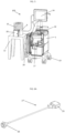
FIG. 1 illustrates an embodiment of the present disclosure wherein the generator, the waste container and the pump are carried on a mobile first platform, and the dose calibrator is carried on a mobile second platform; both platforms are removably attached to each other through a removable attachment of the cabinet structures; and the top surface of the compartment housing the waste container is lower than the top surface of the compartment housing the generator. -
FIG. 2 illustrates an alternative wherein the generator, the pump, the waste container are housed in first cabinet structure and the dose calibrator is housed within a second cabinet structure, both cabinet structures are carried by a single mobile platform bearing two pairs of wheels. -
FIG. 3 illustrates an alternative similar to that shown inFIG. 2 , except that the mobile platform has three pairs of wheels. -
FIG. 4 illustrates an embodiment of the present disclosure that is similar to the embodiment shown inFIG. 1 with the exception that the compartment housing the waste container is higher than the compartment housing the generator. -
FIG. 5 illustrates an alternative wherein the generator, the waste container and the pump are carried on a mobile first platform, and the dose calibrator is positioned on a stationary second platform. -
FIG. 6A and6B illustrate both sections of an electronic cable, where the section of the cable shown inFIG. 6A has a male portion of a magnetic connector, and the other section of the cable shown inFIG. 6B has a female portion of the magnetic connector. -
FIG. 7 illustrates a compartment enclosing the interface of a dose calibrator that is adjacent to the dose calibrator. -
FIG. 8 is a close-up view of an embodiment of the compartment housing the waste container where the door of the compartment is opened and the waste container is housed within an enclosure that may be removed from its compartment. - As used herein, the terms "elution system", "rubidium elution system" and "82Sr/82Rb elution system" can be used interchangeably and refer to a strontium-rubidium infusion system for use in generating a radioactive solution containing rubidium-82, measuring the radioactivity in the solution generated by the system, and infusing the radioactive solution to a patient in order to perform various studies on a patient's organ, such as heart or kidney.
- As used herein, the terms "cart" or "system" or "trolley" are intended to encompass a platform. Said platform can be mobile or stationary.
- As used herein, the terms "primary cart" or "primary mobile cart" refer to a first cart, which can include a first cabinet structure and/or a first platform.
- As used herein, the terms "secondary cart" or "secondary mobile cart" refer to a second cart, which can include a second cabinet structure and/or a second platform.
- The material used for "shielding" is made up of any radiation attenuating material, including, but not limited to, depleted uranium (U), lead (Pb), tin (Sn), antimony (Sb), tungsten (W), bismuth (Bi), any other material, or any combination thereof, as long as it provides a barrier to the radioactivity of rubidium or strontium
- As used herein, the term "shielded component" refers to components of the system that are surrounded by a shielding material, and may refer to the generator, the dose calibrator, the activity detector, the waste container, and/or the tubing line or a part of the tubing line.
- As used herein, the term "non-shielded components" refers to components of the system that are not shielded, such as the pump, the valves, the saline reservoir, the computer, the controller of the system, the interface of the dose calibrator, and/or the tubing line or a part of the tubing line.
- As used herein, the term "cabinet structure" refers to an outer structure of the system that extend upward from a platform and houses an assembly. The cabinet structure may be formed of any radiation resistant material, including, but not limited to, stainless steel, injectionmolded polyurethane, or any other suitable materials or combination thereof.
- As used herein, the expression "locking means for preventing access to the interface by a user of the system" refers to any mechanism, system, or technology to provide security against access by a user to the interface, such as a locked compartment enclosing the interface of the dose calibrator, the requirement for input of a security code or security data (RFID, biometric, numeric, audible, or the like) for modifying the parameters of the interface, integrating the interface into the dose calibrator in such a way that the interface is rendered not accessible, or the like. In an embodiment, only the manufacturer have access to the interface of the dose calibrator. In another embodiment, no one has access to the interface. Being placed outside the primary assembly, the dose calibrator is therefore accessible and it is advantageous to prevent a user from modifying the interface parameters in order to ensure that the dose calibrator remains set properly for the rubidium elution system of the present disclosure.
- As used herein, the term "electronic communication" refers to any electronic transmission or exchange of information, such as a user's commands, configuration of parameters and measurements. The electronic communication between the interface of the dose calibrator and the computer, ensures that measurements taken by the dose calibrator are transferred to the computer, and that said measurements are coordinated with the elution of the sample to be tested by the dose calibrator.
- As used herein, the term "supporting accessories" refers to items such as wheels, lever, paddle, additional saline reservoir, drawer system for housing vials, and a handle for facilitating movement of the system.
- The generator column may be prepared in accordance with
U.S. Patent No. 8,071 ,959 . - The generator system should be able to perform all the desired functions without unwanted and hazardous effects. 82Rb has a half-life of 75 seconds, and its potential impurities, 82Sr and 85Sr, have a half-life of 25.3 days and 64.8 days, respectively. It is essential that patients are not exposed to these undesired isotopes, of which both are characterized by a long half-life. Accordingly, in order to ensure adequate safety, quality control testing of the generator is performed on daily basis prior to use. The daily quality control process for the generator includes collecting an eluted sample in a shielded vial for evaluation, and measuring the activity of the sample in a dose calibrator. Further, the sample is retained to permit decay of all active rubidium, after which a second stage of breakthrough testing is performed. The measured initial activity and the final activity are used to calculate the breakthrough information. The United States Pharmacopeia (USP) provides relevant regulatory limits for breakthrough of strontium of 0.02 µCi of 82Sr/ mCi of 82Rb activity and 0.2 µCi of 85Sr/ mCi of 82Rb activity. Further, to ensure a higher degree of safety, a system may impose a more stringent limit of 50% of the USP limits.
- A constant activity-rate refers to an activity-rate delivered with respect to time wherein the activity-rate is constant with respect to a predetermined constant activity concentration. A method to deliver a constant activity-rate dose is described in
U.S. Patent No. 7,813,841 , - Different elution strategies that can be used for patient infusions include:
- > Constant-Activity elutions, which allow the user to enter the desired activity and duration of the elution. The system automatically estimates a flow rate and controls flow through the generator or a bypass line by a comparison algorithm to achieve activity around the desired set point.
- > Constant-Flow elutions, which allow the user to specify the desired activity and the flow rate. The elution duration is automatically estimated based on the activity vs. volume curve measured during calibration.
- > Constant-Time elutions, which allow the user to specify the desired activity and time for the elution. The flow rate is automatically calculated based on the activity vs. volume curve measured during calibration.
- In an embodiment of the present disclosure, the rubidium elution system includes a controller configured to control the pump and the at least one valve so as to deliver a solution of rubidium at a constant activity rate to a patient. Said controller is preferably included in the primary assembly and carried on a first platform.
-
FIG. 1 shows a front view of a rubidium elution system according to the present disclosure. Theelution system 100 comprises of twomobile platforms platforms platforms wheels 19 mounted on a bottom side of theplatforms first cabinet structure 5 includes a front door 20 (shown inFIG. 5 ) that can be opened in order to access thegenerator 7, tubing circuit and other components. The tubing circuit includes an eluant line 1 that provides an eluant (preferably a saline solution contained in a saline reservoir 13) to thegenerator 7 by means of a pump 8. The tubing circuit also includes a bypass line 2 connected to the eluant line 1 that carries the eluant to the tubing circuit downstream thegenerator 7 such that the eluant bypasses thegenerator 7. The tubing circuit further includes a waste line 3 that directs into a waste container 14 a mixture composed of the eluant fed by the bypass line 2 and the radioactive eluate that has exited thegenerator 7. The tubing circuit also further includes a patient line 4 that directs the same mixture to either i) a patient for infusing said patient with a rubidium solution, or ii) a vial located in thedose calibrator 10 for system's calibration and strontium breakthrough test. Theactivity detector 15 can be a beta detector, a positron detector, or a beta and positron detector. - In certain embodiments, the pump system comprises a pump 8 that can be embodied by a syringe pump, a peristaltic pump, another type of pump, or a combination thereof.
- In the embodiment, the top surface of a compartment housing the
waste container 14 is lower than the top surface of the compartment housing thegenerator 7, as illustrated inFIG. 1 . In another embodiment, the waste container can be at the same elevation than thegenerator 7. In a further embodiment, the top surface of a compartment housing thewaste container 14 is higher than the top surface of the compartment housing thegenerator 7, as illustrated inFIG. 4 . -
FIG. 2 provides a front view of a rubidium elution system, wherein therubidium elution system 100 comprises a first and a second assemblies, and each assembly is housed within afirst cabinet structure 5 and asecond cabinet structure 6, respectively. In this system, bothcabinet structures wheels 19 mounted on a bottom side of the platform 21, in order to allow mobility of the system. Thesecond cabinet structure 6 is an optional element of this system. More particularly, a variant of this system is envisioned where the dose calibrator stands beside the first cabinet structure on the single platform. Ahandle 22 is advantageously provided for manual displacement of the system. Thehandle 22 can be located on the first cabinet structure 5 (not illustrated), on thesecond cabinet structure 6 as shown inFIG. 2 , or on the platform (not illustrated). -
FIG. 3 provides a front view of a further embodiment of therubidium elution 100 system of the present disclosure, where the single platform 21 has three pairs ofwheels 19 that are preferably mounted on a bottom side of the platform 21. -
FIG. 4 illustrates of another embodiment of therubidium elution system 100 of the present invention, which includes a mobilefirst platform 11 and a mobilesecond platform 12. In this embodiment, thewaste container 14 is at an elevation higher than the elevation of thegenerator 7. Therubidium elution system 100 of the present disclosure preferably includes and anactivity detector 15 that is represented with a box for sake of simplicity inFIG. 1-4 . Theactivity detector 15 allows the detection and measurement of the radioactivity in the tubing circuit. Preferably, theactivity detector 15 is positioned downstream thegenerator 7 and the bypass line 2 in order to measure the radioactivity of the mixture of the radioactive eluate exiting thegenerator 7 with the bypassed eluant. The circulation of the fluid (eluant and eluate) in the tubing circuit is obviously ensured via the use of valves 9. Preferably, said at least one valve 9 comprises a valve upstream thegenerator 7 and a valve downstream thegenerator 7. -
FIG. 5 provides a view of an alternativerubidium elution system 100, where thedose calibrator 10 is positioned on a stationarysecond platform 12. InFIG. 5 , the stationarysecond platform 12 is embodied by a stool for sake of the illustration. However, the stationarysecond platform 12 can be a benchtop, a desk, a table, a kiosk, a countertop, or any other fixed location. Thedose calibrator 10 and its shielded compartment are relatively heavy and there is an advantage for the user to move therubidium elution system 100 without thedose calibrator 10. Since thedose calibrator 10 is a sensitive apparatus, positioning the dose calibrator at a fixed location represents an additional benefit. Thedose calibrator 10 is enclosed in a shielded compartment composed of multiple rings of lead positioned on top of each other in order to form a tubular compartment upwardly opened. The illustrations ofFIG. 1-5 show the pile of lead rings and it should be understood that thedose calibrator 10 is located inside these rings of lead. The lead rings provide a strong barrier to radioactivity emission from inside (the sample) and from outside (the surrounding elements containing rubidium and/or strontium). Therefore, the dose calibrator compartment composed of lead rings prevents any interference coming from the surrounding elements with the radioactivity of a sample located inside the lead rings for calibration test and/or breakthrough test. - For the purpose of the breakthrough tests and calibration tests, the primary assembly is preferably placed close to or adjacent to the
dose calibrator 10. The computer of the system can communicate with thedose calibrator 10 via a network (that may optionally include Wi-Fi), via a wireless connection (e.g. Bluetooth) or via a direct electronic connection (e.g. Ethernet, USB or serial cable). For the quality control and calibration tests, a sample of rubidium solution is collected in a vial that is located in the dose calibrator by means of the patient line. In a preferred embodiment, when thedose calibrator 10 is connected to the computer by an electronic cable, said cable is equipped with a breakaway connector. In a preferred embodiment, the breakaway connector is a magnetic connector. An example of a magnetic connector is the Male and Female Magnetic Connector manufactured by Rosenberger Group, Germany, which is illustrated inFIG. 6A and6B . More particularly,FIG. 6A shows onesection 27 of the cable having the male portion 25 of the magnetic connector and aconnector 28 for connecting the interface.FIG. 6B shows the other section 27'of the cable having the female portion 26 of the magnetic connector and a connector 29 for connecting the computer. It should be understood that the present disclosure encompasses other types of breakaway connector that have the ability to detach when the primary assembly is moved away from the dose calibrator. When thecable 27 is connected to thedose calibrator 10 through an interface, said interface is preferably solidly attached to the dose calibrator so that pulling on the cable section 27' results in disconnecting both portions 25 and 26 of the breakaway connector. - According to the embodiments, the first and
second platforms attachment 24 can be achieved through theattachment 24 of thecabinet structures 5 and 6 (indirect attachment as represented inFIG. 1 and4 ) or the attachment can be achieved by the attachment of theplatforms removable attachment 24 is schematically represented by two solid lines inFIG. 1 and4 . For the purpose of this embodiment, any removable attaching means known by a skilled technician can be used. In an embodiment, the dose calibrator is housed in asecond cabinet structure 6. In another embodiment, the dose calibrator is partially housed in a second cabinet structure. In further embodiment, there is no second cabinet structure housing the dose calibrator. In an embodiment, the first andsecond cabinet structures second cabinet structures attachments 24 preferably provide sufficient flexibility to move thecabinet structures - In some embodiments, the 82Sr/82Rb generator, the dose calibrator, the waste container, and the activity detector are each enclosed within respective shielded compartments. Preferably, each of the 82Sr/82Rb generator, the dose calibrator, the waste container, and the activity detector is enclosed within respective shielded compartments. The
door 31 of thewaste compartment 18 is preferably shielded. The opening of the generator is also preferably shielded. - In another aspect, the
second platform 12 include an optional storage compartment, such as a space, tray, drawer, or bin for carrying one or more additional components. Such additional components may include supplies that can include, but are not limited to, tubing for the dose calibrator, vials for the dose calibrator, and other related medical supplies. - In another aspect, the
waste container 14 is housed within an enclosure (shown inFIG. 8 ) that may be removed from its shieldedcompartment 18. In embodiments, thewaste container compartment 18 can be accessed by opening aside door 20 of thefirst cabinet structure 5 in the configurations ofFIG. 1-4 , or by opening atop panel 23 of thefirst cabinet structure 5 as shown inFIG. 5 . In a certain embodiment, thewaste container 14 can be accessed from thewaste container compartment 18 horizontally by mounting a waste platform on rails. In this embodiment, the waste platform is slid out horizontally prior to pulling out thewaste container 14 from its compartment. In another compartment, thewaste container 14 is removed by a lifting mechanism that can be automated. - In certain embodiments, at least one of the first and
second platforms - In other aspects, the computer of the rubidium elution system is configured to proceed with a quality control test (breakthrough tests) at pre-determined time, upon user's request and at least once a day. The computer is configured to prevent a patient infusion when the quality control test result determines that the strontium concentration is equal to or above 0.01 µCi of 82Sr/ mCi of 82Rb activity or equal to or above 0.1 µCi of 85Sr/ mCi of 82Rb activity.
- In accordance with the presently disclosed subject matter, the
dose calibrator 10 is outside the primary assembly. The present disclosure includes embodiments where the dose calibrator is accompanied with its own interface that configures the dose calibrator for detection of rubidium, and with embodiments where the calibrator has no interface and is controlled by the computer. When the dose calibrator is accompanied with its own interface, said interface may be accessible to a user and therefore, there is a need for preventing a user from reconfiguring the interface of thedose calibrator 10. As such, in certain preferred embodiments, the system further includes a locking means for preventing a user from reconfiguring the dose calibrator in such a way that the dose calibrator remains configured as initially configured by the manufacturer. In a preferred embodiment, the dose calibrator is configured to detect rubidium and/or strontium. In a further preferred embodiment, the dose calibrator is configured to detect rubidium. Since strontium and rubidium are in an instant equilibrium, one can use the measured quantity of rubidium to calculate the quantity of strontium that is present in a solution after the initial content in rubidium has decayed. On way to prevent a user from reconfiguring the dose calibrator is to prevent access to the interface of the dose calibrator. In an embodiment, the locking means comprises an identification system for allowing access to the interface and reconfiguring the dose calibrator by the manufacturer of the system and not the user of the system. In another embodiment, the locking means comprises a lockedcompartment 30 as shown inFIG. 5 and7 , which encloses the interface of thedose calibrator 10 and prevents access to by the user of the system. Preferably, the manufacturer of the system remains able to unlock the compartment of the interface and able to configure or reconfigure the dose calibrator as needed. In a variant of this embodiment, the locked compartment enclosing the interface of thedose calibrator 10 is provided by asecond cabinet structure 6 that also encloses or partly encloses thedose calibrator 10. The compartment enclosing the interface can be i) included in the primary assembly, ii) integrated in the dose calibrator, iii) contained a secondary assembly that includes the dose calibrator, or iv) separated from the primary assembly and the dose calibrator. In a further embodiment, there is no interface, and the computer does not allow the user to modify the configurations of the dose calibrator. - In another aspect of the present disclosure, the
rubidium elution system 100 comprises a computer screen 34 (shown inFIG. 5 ) includes a speaker for providing an audible or visible alert for one or more different operations of system. - In another aspect of the present disclosure, the
rubidium elution system 100 comprises a computer that comprises a processor, and a memory communicatively connected to the processor when the system is functioning, as well as processor-executable instructions, that, when executed on the processor, cause the system to perform representative functions of the system. Additionally, certain embodiments may be implemented as computer-executable instructions stored on computer-readable storage media. Computer readable storage media may be distinguished from computer-readable communications media that include transitory signals. - While the presently disclosed subject matter has been described in detail with reference to certain preferred embodiments, it should be appreciated that the present disclosure is not limited to those precise embodiments. Rather, in view of the present disclosure, which describes the current best mode for practicing the disclosed embodiments, many modifications and variations would present themselves to those skilled in the art without departing from the invention, which is defined by the appended claims.
Claims (13)
- A rubidium elution system (100) comprising:a. a primary assembly including a 82Sr/82Rb generator (7), an activity detector (15), a waste container (14), a pump system, a sensor, a tubing circuit, at least one valve (9), and a computer; wherein the primary assembly is housed in a first cabinet structure (5); andb. a dose calibrator (10) that is located outside the first cabinet structure, wherein the dose calibrator and the computer are in electronic communication;characterised in that the primary assembly is positioned on a first platform (11), and the dose calibrator is positioned on a second platform (12); and wherein the first platform and the second platform are mobile; and wherein:(i) the first and second platforms are removably attached together in order to permit movement of the first platform together with the second platform; or(ii) the dose calibrator is housed or partly housed in a second cabinet structure (6), and the first and second cabinet structures are removably attached together so as to permit movement of the first platform together with the second platform.
- The rubidium elution system of claim 1, wherein the electronic communication is wireless.
- The rubidium elution system of claim 1, wherein the electronic communication is via a network system.
- The rubidium elution system of claim 1, wherein the electronic communication is via an electronic cable.
- The rubidium elution system of claim 4, wherein the cable has a breakaway connector.
- The rubidium elution system of claim 5, wherein the breakaway connector is a magnetic connector.
- The rubidium elution system of any one of claims 1 to 6, wherein the system further comprises a locking means for preventing a user of the system from changing a configuration of the dose calibrator.
- The rubidium elution system of claim 7, wherein the system further comprises an interface for configuring the dose calibrator, and wherein the locking means locks the interface in order to prevent the user from reconfiguring the dose calibrator.
- The rubidium elution system of claim 8, wherein the input of a security code or security data is required for modifying the parameters of the interface.
- The rubidium elution system of claim 9, wherein a security code or security data is RFID, biometric, numeric, or audible.
- The rubidium elution system of any one of claims 1 to 10, wherein the computer provides a notification to a user of the system that the dose calibrator is disconnected from the computer, when the dose calibrator and the computer are disconnected from each other.
- The rubidium elution system of any one of claims 1 to 10, wherein the computer provides instructions to a user of the system to connect the dose calibrator with the computer, when i) the user initiates the daily quality control, and ii) the dose calibrator and the computer are disconnected from each other.
- The rubidium elution system of any one of claims 1 to 10, wherein the computer provides a notification to a user of the system that the dose calibrator is connected to the computer, when the dose calibrator and the computer are connected to each other.
Applications Claiming Priority (2)
| Application Number | Priority Date | Filing Date | Title |
|---|---|---|---|
| US201862721042P | 2018-08-22 | 2018-08-22 | |
| PCT/US2019/047687 WO2020041578A1 (en) | 2018-08-22 | 2019-08-22 | 82rb elution system and dose calibrator configurations |
Publications (3)
| Publication Number | Publication Date |
|---|---|
| EP3840688A1 EP3840688A1 (en) | 2021-06-30 |
| EP3840688A4 EP3840688A4 (en) | 2022-05-18 |
| EP3840688B1 true EP3840688B1 (en) | 2024-10-16 |
Family
ID=69591334
Family Applications (1)
| Application Number | Title | Priority Date | Filing Date |
|---|---|---|---|
| EP19851301.2A Active EP3840688B1 (en) | 2018-08-22 | 2019-08-22 | 82rb elution system and dose calibrator configurations |
Country Status (5)
| Country | Link |
|---|---|
| US (1) | US11996209B2 (en) |
| EP (1) | EP3840688B1 (en) |
| CA (1) | CA3110264A1 (en) |
| DK (1) | DK3840688T3 (en) |
| WO (1) | WO2020041578A1 (en) |
Family Cites Families (9)
| Publication number | Priority date | Publication date | Assignee | Title |
|---|---|---|---|---|
| US4585009A (en) | 1983-02-28 | 1986-04-29 | E. R. Squibb & Sons, Inc. | Strontium-rubidium infusion pump with in-line dosimetry |
| WO2007120519A2 (en) | 2006-04-03 | 2007-10-25 | Metro Industries Inc. | Modular workstation |
| US9056164B2 (en) | 2007-01-01 | 2015-06-16 | Bayer Medical Care Inc. | Radiopharmaceutical administration methods, fluid delivery systems and components thereof |
| EP2135630B1 (en) * | 2007-04-09 | 2014-05-07 | Obshchestvo S Ogranichennoy Otvetstvennostiu "Nauchno Proizvodstvennaya Firma 'Pozitom-Pro'" | Automated strontium-rubidium infusion system |
| CA3081018C (en) | 2008-06-11 | 2023-06-13 | Bracco Diagnostics Inc. | Infusion systems including computer-facilitated maintenance and/or operation and methods of use |
| US10943707B2 (en) | 2012-09-05 | 2021-03-09 | Jubilant Draximage, Inc. | Rubidium elution system control |
| US9147965B2 (en) * | 2012-09-26 | 2015-09-29 | Kc Magcon, Inc. | Magnetic-enabled connector device |
| AU2015353373A1 (en) | 2014-11-26 | 2017-06-08 | Spr Therapeutics, Inc. | Electrical stimulator for peripheral stimulation |
| RU2741629C2 (en) * | 2016-09-20 | 2021-01-28 | Бракко Дайэгностикс Инк. | Systems and methods of production, infusion input and control of radioactive isotope delivery |
-
2019
- 2019-08-22 CA CA3110264A patent/CA3110264A1/en active Pending
- 2019-08-22 EP EP19851301.2A patent/EP3840688B1/en active Active
- 2019-08-22 US US17/269,588 patent/US11996209B2/en active Active
- 2019-08-22 WO PCT/US2019/047687 patent/WO2020041578A1/en not_active Ceased
- 2019-08-22 DK DK19851301.2T patent/DK3840688T3/en active
Also Published As
| Publication number | Publication date |
|---|---|
| EP3840688A4 (en) | 2022-05-18 |
| WO2020041578A1 (en) | 2020-02-27 |
| CA3110264A1 (en) | 2020-02-27 |
| US20210313084A1 (en) | 2021-10-07 |
| DK3840688T3 (en) | 2024-10-28 |
| US11996209B2 (en) | 2024-05-28 |
| EP3840688A1 (en) | 2021-06-30 |
Similar Documents
| Publication | Publication Date | Title |
|---|---|---|
| CA2799777C (en) | Activity delivery progress monitor | |
| US9056164B2 (en) | Radiopharmaceutical administration methods, fluid delivery systems and components thereof | |
| US9114203B2 (en) | Infusion systems configurations | |
| US8317674B2 (en) | Shielding assemblies for infusion systems | |
| US20090312630A1 (en) | Infusion systems including computer-facilitated maintenance and/or operation and methods of use | |
| KR20090057979A (en) | Medical devices for the collection, calibration, dilution and / or infusion of injectable radioactive material | |
| CA2989597A1 (en) | Infusion systems including computer-facilitated maintenance and/or operation and methods of use | |
| US20240013946A1 (en) | Elution Protocols and Dosages for Radiopharmaceutical Elution System | |
| US11996209B2 (en) | 82Rb elution system and dose calibrator configurations | |
| US20240299641A1 (en) | 82Rb Elution System Control and Configurations | |
| AU2017235989B2 (en) | Infusion systems including computer-facilitated maintenance and/or operation | |
| US11547798B2 (en) | Installation for the injection of a radioactive product into a patient and method for the implementation thereof | |
| AU2011261190B2 (en) | Activity delivery progress monitor |
Legal Events
| Date | Code | Title | Description |
|---|---|---|---|
| STAA | Information on the status of an ep patent application or granted ep patent |
Free format text: STATUS: THE INTERNATIONAL PUBLICATION HAS BEEN MADE |
|
| PUAI | Public reference made under article 153(3) epc to a published international application that has entered the european phase |
Free format text: ORIGINAL CODE: 0009012 |
|
| STAA | Information on the status of an ep patent application or granted ep patent |
Free format text: STATUS: REQUEST FOR EXAMINATION WAS MADE |
|
| 17P | Request for examination filed |
Effective date: 20210317 |
|
| AK | Designated contracting states |
Kind code of ref document: A1 Designated state(s): AL AT BE BG CH CY CZ DE DK EE ES FI FR GB GR HR HU IE IS IT LI LT LU LV MC MK MT NL NO PL PT RO RS SE SI SK SM TR |
|
| DAV | Request for validation of the european patent (deleted) | ||
| DAX | Request for extension of the european patent (deleted) | ||
| A4 | Supplementary search report drawn up and despatched |
Effective date: 20220420 |
|
| RIC1 | Information provided on ipc code assigned before grant |
Ipc: B62B 3/00 20060101ALI20220412BHEP Ipc: A61M 5/00 20060101ALI20220412BHEP Ipc: A61B 50/10 20160101ALI20220412BHEP Ipc: G21G 1/00 20060101AFI20220412BHEP |
|
| REG | Reference to a national code |
Ref legal event code: R079 Ipc: G21G0001000000 Ref country code: DE Ref legal event code: R079 Ref document number: 602019060604 Country of ref document: DE Free format text: PREVIOUS MAIN CLASS: A61B0050100000 Ipc: G21G0001000000 |
|
| GRAP | Despatch of communication of intention to grant a patent |
Free format text: ORIGINAL CODE: EPIDOSNIGR1 |
|
| STAA | Information on the status of an ep patent application or granted ep patent |
Free format text: STATUS: GRANT OF PATENT IS INTENDED |
|
| RIC1 | Information provided on ipc code assigned before grant |
Ipc: B62B 3/00 20060101ALI20240604BHEP Ipc: A61M 5/00 20060101ALI20240604BHEP Ipc: A61B 50/10 20160101ALI20240604BHEP Ipc: G21G 1/00 20060101AFI20240604BHEP |
|
| INTG | Intention to grant announced |
Effective date: 20240702 |
|
| GRAS | Grant fee paid |
Free format text: ORIGINAL CODE: EPIDOSNIGR3 |
|
| GRAA | (expected) grant |
Free format text: ORIGINAL CODE: 0009210 |
|
| STAA | Information on the status of an ep patent application or granted ep patent |
Free format text: STATUS: THE PATENT HAS BEEN GRANTED |
|
| AK | Designated contracting states |
Kind code of ref document: B1 Designated state(s): AL AT BE BG CH CY CZ DE DK EE ES FI FR GB GR HR HU IE IS IT LI LT LU LV MC MK MT NL NO PL PT RO RS SE SI SK SM TR |
|
| REG | Reference to a national code |
Ref country code: GB Ref legal event code: FG4D |
|
| REG | Reference to a national code |
Ref country code: NL Ref legal event code: FP |
|
| REG | Reference to a national code |
Ref country code: DK Ref legal event code: T3 Effective date: 20241023 |
|
| REG | Reference to a national code |
Ref country code: CH Ref legal event code: EP |
|
| REG | Reference to a national code |
Ref country code: IE Ref legal event code: FG4D |
|
| REG | Reference to a national code |
Ref country code: DE Ref legal event code: R096 Ref document number: 602019060604 Country of ref document: DE |
|
| P01 | Opt-out of the competence of the unified patent court (upc) registered |
Free format text: CASE NUMBER: APP_55860/2024 Effective date: 20241011 |
|
| REG | Reference to a national code |
Ref country code: LT Ref legal event code: MG9D |
|
| REG | Reference to a national code |
Ref country code: AT Ref legal event code: MK05 Ref document number: 1733637 Country of ref document: AT Kind code of ref document: T Effective date: 20241016 |
|
| PG25 | Lapsed in a contracting state [announced via postgrant information from national office to epo] |
Ref country code: PT Free format text: LAPSE BECAUSE OF FAILURE TO SUBMIT A TRANSLATION OF THE DESCRIPTION OR TO PAY THE FEE WITHIN THE PRESCRIBED TIME-LIMIT Effective date: 20250217 Ref country code: HR Free format text: LAPSE BECAUSE OF FAILURE TO SUBMIT A TRANSLATION OF THE DESCRIPTION OR TO PAY THE FEE WITHIN THE PRESCRIBED TIME-LIMIT Effective date: 20241016 Ref country code: IS Free format text: LAPSE BECAUSE OF FAILURE TO SUBMIT A TRANSLATION OF THE DESCRIPTION OR TO PAY THE FEE WITHIN THE PRESCRIBED TIME-LIMIT Effective date: 20250216 |
|
| PG25 | Lapsed in a contracting state [announced via postgrant information from national office to epo] |
Ref country code: FI Free format text: LAPSE BECAUSE OF FAILURE TO SUBMIT A TRANSLATION OF THE DESCRIPTION OR TO PAY THE FEE WITHIN THE PRESCRIBED TIME-LIMIT Effective date: 20241016 |
|
| PG25 | Lapsed in a contracting state [announced via postgrant information from national office to epo] |
Ref country code: BG Free format text: LAPSE BECAUSE OF FAILURE TO SUBMIT A TRANSLATION OF THE DESCRIPTION OR TO PAY THE FEE WITHIN THE PRESCRIBED TIME-LIMIT Effective date: 20241016 |
|
| PG25 | Lapsed in a contracting state [announced via postgrant information from national office to epo] |
Ref country code: ES Free format text: LAPSE BECAUSE OF FAILURE TO SUBMIT A TRANSLATION OF THE DESCRIPTION OR TO PAY THE FEE WITHIN THE PRESCRIBED TIME-LIMIT Effective date: 20241016 |
|
| PG25 | Lapsed in a contracting state [announced via postgrant information from national office to epo] |
Ref country code: NO Free format text: LAPSE BECAUSE OF FAILURE TO SUBMIT A TRANSLATION OF THE DESCRIPTION OR TO PAY THE FEE WITHIN THE PRESCRIBED TIME-LIMIT Effective date: 20250116 |
|
| PG25 | Lapsed in a contracting state [announced via postgrant information from national office to epo] |
Ref country code: AT Free format text: LAPSE BECAUSE OF FAILURE TO SUBMIT A TRANSLATION OF THE DESCRIPTION OR TO PAY THE FEE WITHIN THE PRESCRIBED TIME-LIMIT Effective date: 20241016 Ref country code: GR Free format text: LAPSE BECAUSE OF FAILURE TO SUBMIT A TRANSLATION OF THE DESCRIPTION OR TO PAY THE FEE WITHIN THE PRESCRIBED TIME-LIMIT Effective date: 20250117 Ref country code: LV Free format text: LAPSE BECAUSE OF FAILURE TO SUBMIT A TRANSLATION OF THE DESCRIPTION OR TO PAY THE FEE WITHIN THE PRESCRIBED TIME-LIMIT Effective date: 20241016 |
|
| PG25 | Lapsed in a contracting state [announced via postgrant information from national office to epo] |
Ref country code: PL Free format text: LAPSE BECAUSE OF FAILURE TO SUBMIT A TRANSLATION OF THE DESCRIPTION OR TO PAY THE FEE WITHIN THE PRESCRIBED TIME-LIMIT Effective date: 20241016 |
|
| PG25 | Lapsed in a contracting state [announced via postgrant information from national office to epo] |
Ref country code: RS Free format text: LAPSE BECAUSE OF FAILURE TO SUBMIT A TRANSLATION OF THE DESCRIPTION OR TO PAY THE FEE WITHIN THE PRESCRIBED TIME-LIMIT Effective date: 20250116 |
|
| PG25 | Lapsed in a contracting state [announced via postgrant information from national office to epo] |
Ref country code: SM Free format text: LAPSE BECAUSE OF FAILURE TO SUBMIT A TRANSLATION OF THE DESCRIPTION OR TO PAY THE FEE WITHIN THE PRESCRIBED TIME-LIMIT Effective date: 20241016 |
|
| REG | Reference to a national code |
Ref country code: DE Ref legal event code: R097 Ref document number: 602019060604 Country of ref document: DE |
|
| PG25 | Lapsed in a contracting state [announced via postgrant information from national office to epo] |
Ref country code: EE Free format text: LAPSE BECAUSE OF FAILURE TO SUBMIT A TRANSLATION OF THE DESCRIPTION OR TO PAY THE FEE WITHIN THE PRESCRIBED TIME-LIMIT Effective date: 20241016 |
|
| PG25 | Lapsed in a contracting state [announced via postgrant information from national office to epo] |
Ref country code: RO Free format text: LAPSE BECAUSE OF FAILURE TO SUBMIT A TRANSLATION OF THE DESCRIPTION OR TO PAY THE FEE WITHIN THE PRESCRIBED TIME-LIMIT Effective date: 20241016 |
|
| PG25 | Lapsed in a contracting state [announced via postgrant information from national office to epo] |
Ref country code: SK Free format text: LAPSE BECAUSE OF FAILURE TO SUBMIT A TRANSLATION OF THE DESCRIPTION OR TO PAY THE FEE WITHIN THE PRESCRIBED TIME-LIMIT Effective date: 20241016 |
|
| PG25 | Lapsed in a contracting state [announced via postgrant information from national office to epo] |
Ref country code: CZ Free format text: LAPSE BECAUSE OF FAILURE TO SUBMIT A TRANSLATION OF THE DESCRIPTION OR TO PAY THE FEE WITHIN THE PRESCRIBED TIME-LIMIT Effective date: 20241016 |
|
| PG25 | Lapsed in a contracting state [announced via postgrant information from national office to epo] |
Ref country code: IT Free format text: LAPSE BECAUSE OF FAILURE TO SUBMIT A TRANSLATION OF THE DESCRIPTION OR TO PAY THE FEE WITHIN THE PRESCRIBED TIME-LIMIT Effective date: 20241016 |
|
| PLBE | No opposition filed within time limit |
Free format text: ORIGINAL CODE: 0009261 |
|
| STAA | Information on the status of an ep patent application or granted ep patent |
Free format text: STATUS: NO OPPOSITION FILED WITHIN TIME LIMIT |
|
| PG25 | Lapsed in a contracting state [announced via postgrant information from national office to epo] |
Ref country code: SE Free format text: LAPSE BECAUSE OF FAILURE TO SUBMIT A TRANSLATION OF THE DESCRIPTION OR TO PAY THE FEE WITHIN THE PRESCRIBED TIME-LIMIT Effective date: 20241016 |
|
| PGFP | Annual fee paid to national office [announced via postgrant information from national office to epo] |
Ref country code: LU Payment date: 20250822 Year of fee payment: 7 Ref country code: NL Payment date: 20250826 Year of fee payment: 7 |
|
| 26N | No opposition filed |
Effective date: 20250717 |
|
| PGFP | Annual fee paid to national office [announced via postgrant information from national office to epo] |
Ref country code: DE Payment date: 20250828 Year of fee payment: 7 Ref country code: DK Payment date: 20250822 Year of fee payment: 7 |
|
| PGFP | Annual fee paid to national office [announced via postgrant information from national office to epo] |
Ref country code: GB Payment date: 20250827 Year of fee payment: 7 |
|
| REG | Reference to a national code |
Ref country code: CH Ref legal event code: H13 Free format text: ST27 STATUS EVENT CODE: U-0-0-H10-H13 (AS PROVIDED BY THE NATIONAL OFFICE) Effective date: 20260324 |
|
| PG25 | Lapsed in a contracting state [announced via postgrant information from national office to epo] |
Ref country code: MC Free format text: LAPSE BECAUSE OF FAILURE TO SUBMIT A TRANSLATION OF THE DESCRIPTION OR TO PAY THE FEE WITHIN THE PRESCRIBED TIME-LIMIT Effective date: 20241016 |
|
| PG25 | Lapsed in a contracting state [announced via postgrant information from national office to epo] |
Ref country code: CH Free format text: LAPSE BECAUSE OF NON-PAYMENT OF DUE FEES Effective date: 20250831 |
|
| REG | Reference to a national code |
Ref country code: BE Ref legal event code: MM Effective date: 20250831 |
|
| PG25 | Lapsed in a contracting state [announced via postgrant information from national office to epo] |
Ref country code: LT Free format text: LAPSE BECAUSE OF FAILURE TO SUBMIT A TRANSLATION OF THE DESCRIPTION OR TO PAY THE FEE WITHIN THE PRESCRIBED TIME-LIMIT Effective date: 20241016 |
|
| PG25 | Lapsed in a contracting state [announced via postgrant information from national office to epo] |
Ref country code: BE Free format text: LAPSE BECAUSE OF NON-PAYMENT OF DUE FEES Effective date: 20250831 Ref country code: IE Free format text: LAPSE BECAUSE OF NON-PAYMENT OF DUE FEES Effective date: 20250822 |
|
| PG25 | Lapsed in a contracting state [announced via postgrant information from national office to epo] |
Ref country code: FR Free format text: LAPSE BECAUSE OF NON-PAYMENT OF DUE FEES Effective date: 20250831 |