EP3840398B1 - A wireless hearing device and a charging base - Google Patents
A wireless hearing device and a charging base Download PDFInfo
- Publication number
- EP3840398B1 EP3840398B1 EP20214193.3A EP20214193A EP3840398B1 EP 3840398 B1 EP3840398 B1 EP 3840398B1 EP 20214193 A EP20214193 A EP 20214193A EP 3840398 B1 EP3840398 B1 EP 3840398B1
- Authority
- EP
- European Patent Office
- Prior art keywords
- contacts
- band
- hearing device
- wireless hearing
- support
- Prior art date
- Legal status (The legal status is an assumption and is not a legal conclusion. Google has not performed a legal analysis and makes no representation as to the accuracy of the status listed.)
- Active
Links
Images




Classifications
-
- H—ELECTRICITY
- H04—ELECTRIC COMMUNICATION TECHNIQUE
- H04R—LOUDSPEAKERS, MICROPHONES, GRAMOPHONE PICK-UPS OR LIKE ACOUSTIC ELECTROMECHANICAL TRANSDUCERS; ELECTRIC HEARING AIDS; PUBLIC ADDRESS SYSTEMS
- H04R1/00—Details of transducers, loudspeakers or microphones
- H04R1/10—Earpieces; Attachments therefor ; Earphones; Monophonic headphones
- H04R1/1025—Accumulators specially adapted for earpieces; Arrangements specially adapted for charging thereof
-
- H—ELECTRICITY
- H02—GENERATION; CONVERSION OR DISTRIBUTION OF ELECTRIC POWER
- H02J—ELECTRIC POWER NETWORKS; CIRCUIT ARRANGEMENTS OR SYSTEMS FOR SUPPLYING OR DISTRIBUTING ELECTRIC POWER; SYSTEMS FOR STORING ELECTRIC ENERGY
- H02J7/00—Circuit arrangements for charging or discharging batteries or for supplying loads from batteries
- H02J7/70—Circuit arrangements for charging or discharging batteries or for supplying loads from batteries characterised by the mechanical construction
- H02J7/731—Circuit arrangements for charging or discharging batteries or for supplying loads from batteries characterised by the mechanical construction specially adapted for holding portable devices containing batteries
-
- H—ELECTRICITY
- H04—ELECTRIC COMMUNICATION TECHNIQUE
- H04R—LOUDSPEAKERS, MICROPHONES, GRAMOPHONE PICK-UPS OR LIKE ACOUSTIC ELECTROMECHANICAL TRANSDUCERS; ELECTRIC HEARING AIDS; PUBLIC ADDRESS SYSTEMS
- H04R5/00—Stereophonic arrangements
- H04R5/033—Headphones for stereophonic communication
- H04R5/0335—Earpiece support, e.g. headbands or neckrests
-
- H—ELECTRICITY
- H04—ELECTRIC COMMUNICATION TECHNIQUE
- H04R—LOUDSPEAKERS, MICROPHONES, GRAMOPHONE PICK-UPS OR LIKE ACOUSTIC ELECTROMECHANICAL TRANSDUCERS; ELECTRIC HEARING AIDS; PUBLIC ADDRESS SYSTEMS
- H04R1/00—Details of transducers, loudspeakers or microphones
- H04R1/10—Earpieces; Attachments therefor ; Earphones; Monophonic headphones
- H04R1/1008—Earpieces of the supra-aural or circum-aural type
-
- H—ELECTRICITY
- H04—ELECTRIC COMMUNICATION TECHNIQUE
- H04R—LOUDSPEAKERS, MICROPHONES, GRAMOPHONE PICK-UPS OR LIKE ACOUSTIC ELECTROMECHANICAL TRANSDUCERS; ELECTRIC HEARING AIDS; PUBLIC ADDRESS SYSTEMS
- H04R2420/00—Details of connection covered by H04R, not provided for in its groups
- H04R2420/07—Applications of wireless loudspeakers or wireless microphones
Definitions
- the invention to a wireless hearing device system comprising a wireless hearing device and a charging base, wherein the wireless hearing device comprises a first earphone, a connecting band extending from the first earphone, a rechargeable battery and band contacts arranged on the connecting band, and wherein the charging base comprises a band support with support contacts, whereby the hearing device can be docked in the base, such that the band contacts are in electrical contact with the support contacts, whereby the rechargeable battery can be recharged.
- US 7,639,832 B2 discloses a hearing device according to the preamble.
- a disadvantage with such a system is, that the user must carefully align the band contact and the support contact in order to secure correct docking for recharging.
- US 2019/373353 A1 discloses an earphone for charging transmission through an earphone metal headband fixed into a housing. One end of the metal headband is welded with a metal bracket, the other end of the metal bracket is welded to a PCB. A wireless charging coil is fixed into the housing and the wireless charging coil of the housing is electrically connected with a battery inside the housing through the PCB.
- EP 0 389 174 A1 and WO 2018/146088 A1 also relate to wirelessly charged hearing devices.
- the hearing device system is characterised in that the connecting band and the band support are adapted to be engageable in a contact range, within which the connecting band and the band support can be displaced in relation to each other in the longitudinal direction of the connecting band, and in that that the band contacts and the support contacts are embodied to be in electrical contact with each other in any position within this contact range.
- the connecting band and the band support only need to be aligned in the transversal direction, and within the contact range in the longitudinal direction. This makes it easer and faster for the user to dock the hearing device.
- the connecting band is a headband comprising a bottom face facing the user's head when the hearing device is worn, an opposite top face facing away from the user's head, when the hearing device is worn, and two opposite side faces connecting the bottom face and the top face.
- the band contacts are arranged on the bottom face.
- the band contacts are arranged in recesses, so their surfaces are retracted from the remaining surface of the bottom face.
- the contacts can be made of hard metallic material without causing discomfort for the user when worn.
- the band contacts are made of soft, electrical conducting material, such as electrically conductive silicon rubber. If a head band is provided with such contacts, the comfort level can be maintained compared to a traditional headband with no contacts.
- the band contacts are arranged on the side faces.
- the bottom face can be made of any material in order to optimise the comfort for the user wearing the hearing device.
- the band contacts are embodied as two rows of separate interconnected contacts.
- Such a solution can be an advantage for different reasons, f. ex. in order to make the band bendable to adapt it to different head sizes or simple design purposes.
- the band contacts are embodied as longitudinal rails extending along the longitudinal direction of the connecting band. These rails can be at least 4 cm, 6 cm, 8 cm, 10 cm, 12 cm, 14 cm or 16 cm long.
- the support contacts are embodied as point shaped contacts, such as pogo pins.
- the support contacts are embodied as longitudinal rails. These rails can be at least 4 cm, 6 cm, 8 cm, 10 cm, 12 cm, 14 cm or 16 cm long.
- the band contacts are embodied as point shaped contacts, such as pogo pins.
- a wireless hearing device system according to any of the preceding claims, wherein the contact range is at least 4 cm, 6 cm, 8 cm, 10 cm, 12 cm, 14 cm or 16 cm. The longer the range is, the less accurate the user needs to be when docking the hearing device.
- the band contacts comprise a first central contact with a first polarity and second contact on each side of the first contact with a second polarity.
- the support contacts comprise a first central contact with a first polarity and second contact on each side of the first contact with a second polarity.
- Fig. 1 is a front view of a wireless headset system 1 comprising a wireless hearing device 2 and a charging base 3 according to a first embodiment of the invention.
- the hearing device is a wireless headset 3 comprising a first earphone 8, a second earphone 18, a headband 4 connecting the first and second earphones 8, 18 and a microphone arm 9 extending from the first earphone 8.
- the headset 2 is wireless and is therefore provided with a rechargeable battery 5 in the first earphone 8.
- the battery 5 is in electrical contact with headband contacts 6 (see fig. 4 ) on the headband 4.
- the headband 4 comprises a bottom face 12 facing the user's head when the headset 2 is worn, an opposite top face 14 facing away from the user's head, when the hearing device 2 is worn, and two side faces 13 connecting the bottom face 12 and the top face 14. Details such as speakers, microphones, sound processing electronics, radio transceiver etc. which are not relevant for the invention, will not be described here.
- the charging base 3 comprises a foot 16, a pole 15 extending from the foot 16 and a band support 10 at the upper end of the pole 15. In fig. 1 , the headset 2 is resting with the headband 4 on the band support 10 in a first charging position, where the headband contacts 6 are in contact with the support contacts 7 (see fig. 4 ).
- the base 3 comprises electronics and a power supply, which is not relevant for the invention and therefore not will be described further here.
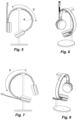
- Fig. 2 is a side view of the headset system 1 with the headset 2 in the first charging position.
- the headband 4 is received in a recess 17 in the upper face of the band support 10.
- Fig. 3 is a perspective view of the first embodiment with the headset 1 in the first charging position.
- Fig. 4 is a perspective view of the first embodiment with the headset 1 removed from the charging base 3.
- the headband contacts are embodied as two longitudinal rails 6 running on the bottom face 12 of the headband 4 in the longitudinal direction 11 of the headband 4.
- the support contacts are embodied as two short parallel rails 7 in the bottom of the support recess 17. When the headband 4 is received in the support recess 17, the two band contacts 6 are in contact with the two support contacts 7, whereby charging current can run to and recharge the battery 5.
- the headband 4 is held in place in sideways direction by recess sidewalls 19.
- Figs. 5 and 6 are a front and perspective views of the first embodiment, where the headset 2 is arranged in a second charging position.
- the headband contacts 6 are approximately 16 cm long and defines a "charging range" of the headband 4.
- the headband 4 can be arranged in the support in any position within this range X and still be charged.
- the user does not need to carefully align the headband contacts 6 with the support contacts 7 every time he arranges the headset 2 on the charging base 3 for charging. He just needs to be within the range X, which in this case is about approximately 16 cm. However, it could have other values, such as at least 4 cm, 6 cm, 8 cm, 10 cm, 12 cm or 14 cm.
- Figs. 7 and 8 are front and perspective views of the first embodiment, where the headset 2 is arranged in a third charging position.
- the longitudinal headband contacts 6 can be made of metal strips, which or more or les flexible. However, they could also be made compliant conducting material, such as electrically conductive silicone.
- Fig. 9 is a perspective view of a headset 2b of a wireless hearing device system according to a second embodiment.
- the headband contacts 6b are embodied as longitudinal rails 6b running in the longitudinal direction of the headband 4b on the side faces 13b of the headband 4b.
- the bottom face 12b can be made of soft nonconducting material, which is comfortable for the headset user.
- Fig. 10 is a front view of the wireless hearing device system of the second embodiment.
- Fig. 11 is a schematic cross-sectional view through a part of the wireless hearing device system of the second embodiment.
- the headband contacts 6b are arranged on the side faces 13b of the headband.
- the bottom face 12b of the headband is made of soft rubber material.
- the support contacts 7b are arranged on sloping sidewalls 19b of the support recess 17b.
- Fig. 12 is a schematic longitudinal section of a part of a wireless hearing device system according to a third embodiment.
- the headband contacts are longitudinal rails 6c on the bottom face 12c of the headband 4c.
- the support contacts are a pair more or less point shaped contacts, f. ex. of pogo pins 7c.
- Fig. 13 is a schematic longitudinal section of a part of a wireless hearing device system according to a fourth embodiment.
- the headband contacts are a pair of more or less point shaped contacts, f. ex. pogo pins 6d.
- the support contacts are shaped as longitudinal rails 7d on the top face of the support 10d.
- Fig. 14 is a schematic longitudinal section of a part of a wireless hearing device system according to a fifth embodiment.
- the headband contacts are embodied as two rows of separate contacts 6e.
- the support contacts are embodied as two small plate shaped contacts 7e.
- the headband contacts 6e and the support contacts 7e are shaped and dimensioned, such that each support contact 7e will always touch a headband contact 6e as long as it is within the range X of headband contacts 6e.
- Fig. 15 is a schematic cross-sectional view of a part of a wireless hearing system according to a sixth embodiment.
- the headband contacts are embodied as longitudinal rails 6f arranged in recessions in the bottom face 12 of the headband 4f.
- the support contacts are pin-shaped contacts 7f with a length whereby they can reach into the headband contacts 6f, when the headset 2 is docked.
- the advantage of the headband contacts 6f being arranged in the bottom of recesses is, that they can be made of hard metallic material without causing discomfort for the user wearing the headset 2.
- the bottom face 12 can be made of pliant material.
- Fig. 16 is a schematic cross-sectional view of a part of a wireless hearing device system according to a seventh embodiment.
- the headband 4g has three band contacts 6g
- the support 10g has three support contacts 7.
- Each of the headband's 4g side faces 13 has a longitudinal band contact 6g with "-" polarity
- the headband's 4g bottom face 12 g has a longitudinal contact 6g with "+” polarity.
- the support recess 17 g has corresponding contacts 7g with "+" polarity on the sidewalls and a contact 7g with "-" polarity on the bottom wall.
- Fig. 17 is a schematic cross-sectional view of a part of a wireless hearing device system according to an eighth embodiment.
- This embodiment is symmetrical like the seventh embodiment with three pairs of contacts 6h, 7h. All the band contacts 6h are arranged on the bottom face 12h of the headband 4h, and all the support contacts 7h are arranged on the bottom wall of the support recess 17h.
- Fig. 18 is a schematic cross-sectional view of a part of a wireless hearing device system according to a ninth embodiment. This embodiment differs only from the embodiments shown in Fig. 17 by the headband only comprises two contacts 6i. No matter which direction the user arranges the headband 4i in, both poles of the band contacts 6i and the support contacts 7i will be connected.
- Fig. 19 is a perspective view of the first embodiment in an opposite charging position compared to the charging position shown in Fig. 3 .
- the headset 2 is turned 180 degrees in relation to the charging base.
- Fig. 20 is a logic switch to solve polarity issues occurring when turning the headset 180 degrees in the embodiments 1-6.
- the switch comprises a rectifier bridge or diode bridge that provides the same polarity of output for either polarity of input.
- safety circuitry could also ensure, that charging current will not run before proper docking is sensed, f. ex. by means if a magnet in the headband and a hall sensor in the support.
- the headset 2 itself could be provided with circuitry protecting it against short circuits and electrostatic discharge (ESD).
- ESD electrostatic discharge
- the headsets are duo headset comprising two earphones.
- the invention could also be exploited with mono headsets only comprising one earphone.
- a neckband could be used for docking the headset.
- hearing device also comprises headphones, which are not capable of two-way communication.
- the range X within the band and the support can be displaced in relation to each other can be f. ex. 4 cm, 6 cm, 8 cm, 10 cm, 12 cm, 14 cm or 16 cm.
Landscapes
- Engineering & Computer Science (AREA)
- Physics & Mathematics (AREA)
- Acoustics & Sound (AREA)
- Signal Processing (AREA)
- Power Engineering (AREA)
- Charge And Discharge Circuits For Batteries Or The Like (AREA)
Description
- The invention to a wireless hearing device system comprising a wireless hearing device and a charging base, wherein the wireless hearing device comprises a first earphone, a connecting band extending from the first earphone, a rechargeable battery and band contacts arranged on the connecting band, and wherein the charging base comprises a band support with support contacts, whereby the hearing device can be docked in the base, such that the band contacts are in electrical contact with the support contacts, whereby the rechargeable battery can be recharged.
-
US 7,639,832 B2 discloses a hearing device according to the preamble. A disadvantage with such a system is, that the user must carefully align the band contact and the support contact in order to secure correct docking for recharging. There is a need for a more convenient system, where the user in an easy, but still reliable way can dock the hearing device on the charging base. -
US 2019/373353 A1 discloses an earphone for charging transmission through an earphone metal headband fixed into a housing. One end of the metal headband is welded with a metal bracket, the other end of the metal bracket is welded to a PCB. A wireless charging coil is fixed into the housing and the wireless charging coil of the housing is electrically connected with a battery inside the housing through the PCB. -
EP 0 389 174 A1 andWO 2018/146088 A1 also relate to wirelessly charged hearing devices. - The hearing device system according to the preliminary part is characterised in that the connecting band and the band support are adapted to be engageable in a contact range, within which the connecting band and the band support can be displaced in relation to each other in the longitudinal direction of the connecting band, and in that that the band contacts and the support contacts are embodied to be in electrical contact with each other in any position within this contact range. Thus, the user does not have to precisely align the band contacts and the support contacts when docking the hearing device. The connecting band and the band support only need to be aligned in the transversal direction, and within the contact range in the longitudinal direction. This makes it easer and faster for the user to dock the hearing device.
- According to an embodiment, the connecting band is a headband comprising a bottom face facing the user's head when the hearing device is worn, an opposite top face facing away from the user's head, when the hearing device is worn, and two opposite side faces connecting the bottom face and the top face.
- According to an embodiment, the band contacts are arranged on the bottom face.
- According to an embodiment, the band contacts are arranged in recesses, so their surfaces are retracted from the remaining surface of the bottom face. Hereby the contacts can be made of hard metallic material without causing discomfort for the user when worn.
- According to an embodiment, the band contacts are made of soft, electrical conducting material, such as electrically conductive silicon rubber. If a head band is provided with such contacts, the comfort level can be maintained compared to a traditional headband with no contacts.
- According to another embodiment, the band contacts are arranged on the side faces. With such a solution, the bottom face can be made of any material in order to optimise the comfort for the user wearing the hearing device.
- According to an embodiment, the band contacts are embodied as two rows of separate interconnected contacts. Such a solution can be an advantage for different reasons, f. ex. in order to make the band bendable to adapt it to different head sizes or simple design purposes.
- According to an embodiment, the band contacts are embodied as longitudinal rails extending along the longitudinal direction of the connecting band. These rails can be at least 4 cm, 6 cm, 8 cm, 10 cm, 12 cm, 14 cm or 16 cm long.
- According to an embodiment, the support contacts are embodied as point shaped contacts, such as pogo pins.
- According to an embodiment, the support contacts are embodied as longitudinal rails. These rails can be at least 4 cm, 6 cm, 8 cm, 10 cm, 12 cm, 14 cm or 16 cm long.
- According to an embodiment, the band contacts are embodied as point shaped contacts, such as pogo pins.
- A wireless hearing device system according to any of the preceding claims, wherein the contact range is at least 4 cm, 6 cm, 8 cm, 10 cm, 12 cm, 14 cm or 16 cm. The longer the range is, the less accurate the user needs to be when docking the hearing device.
- According to an embodiment, the band contacts comprise a first central contact with a first polarity and second contact on each side of the first contact with a second polarity.
- According to an embodiment, the support contacts comprise a first central contact with a first polarity and second contact on each side of the first contact with a second polarity.
- The invention is explained in detail below with reference to the drawing illustrating a preferred embodiment of the invention and in which
-
Fig. 1 is a front view of a wireless hearing device system comprising a wireless hearing device and a charging base according to a first embodiment of the invention, wherein the hearing device is arranged in a first charging position, -
Fig. 2 is a side view of the first embodiment, -
Fig. 3 is a perspective view of the first embodiment, -
Fig. 4 is a perspective view of the first embodiment with the hearing device removed from the charging base, -
Fig. 5 . is a front view of the first embodiment, where the hearing device is arranged in a second charging position, -
Fig. 6 is a perspective view of the first embodiment, where the hearing device is arranged in the second charging position, -
Fig. 7 is a front view of the first embodiment, where the hearing device is arranged in a third charging position, -
Fig. 8 a perspective view of the first embodiment, where the hearing device is arranged in the third charging position, -
Fig. 9 is a perspective view of a hearing device of a wireless hearing device system according to a second embodiment, -
Fig. 10 is a front view of the wireless hearing device system of the second embodiment, -
Fig. 11 is a schematic cross-sectional view through a part of the wireless hearing device system of the second embodiment, -
Fig. 12 is a schematic longitudinal section of a part of a wireless hearing device system according to a third embodiment, -
Fig. 13 is a schematic longitudinal section of a part of a wireless hearing device system according to a fourth embodiment, -
Fig. 14 is a schematic longitudinal section of a part of a wireless hearing device system according to a fifth embodiment, -
Fig. 15 is a schematic cross-sectional view of a part of a wireless hearing device system according to a sixth embodiment, -
Fig. 16 is a schematic cross-sectional view of a part of a wireless hearing device system according to a seventh embodiment, -
Fig. 17 is a schematic cross-sectional view of a part of a wireless hearing device system according to an eighth embodiment, -
Fig. 18 is a schematic cross-sectional view of a part of a wireless hearing device system according to a ninth embodiment, -
Fig. 19 is a perspective view of the first embodiment in an opposite charging position compared to the charging position shown inFig. 3 , and -
Fig. 20 is a logic switch to solve polarity issues. -
Fig. 1 is a front view of awireless headset system 1 comprising awireless hearing device 2 and acharging base 3 according to a first embodiment of the invention. The hearing device is awireless headset 3 comprising afirst earphone 8, a second earphone 18, aheadband 4 connecting the first andsecond earphones 8, 18 and amicrophone arm 9 extending from thefirst earphone 8. Theheadset 2 is wireless and is therefore provided with arechargeable battery 5 in thefirst earphone 8. Thebattery 5 is in electrical contact with headband contacts 6 (seefig. 4 ) on theheadband 4. Theheadband 4 comprises abottom face 12 facing the user's head when theheadset 2 is worn, an oppositetop face 14 facing away from the user's head, when thehearing device 2 is worn, and two side faces 13 connecting thebottom face 12 and thetop face 14. Details such as speakers, microphones, sound processing electronics, radio transceiver etc. which are not relevant for the invention, will not be described here. The chargingbase 3 comprises afoot 16, apole 15 extending from thefoot 16 and aband support 10 at the upper end of thepole 15. Infig. 1 , theheadset 2 is resting with theheadband 4 on theband support 10 in a first charging position, where theheadband contacts 6 are in contact with the support contacts 7 (seefig. 4 ). Thebase 3 comprises electronics and a power supply, which is not relevant for the invention and therefore not will be described further here. -
Fig. 2 is a side view of theheadset system 1 with theheadset 2 in the first charging position. Theheadband 4 is received in arecess 17 in the upper face of theband support 10. -
Fig. 3 is a perspective view of the first embodiment with theheadset 1 in the first charging position. -
Fig. 4 is a perspective view of the first embodiment with theheadset 1 removed from the chargingbase 3. The headband contacts are embodied as twolongitudinal rails 6 running on thebottom face 12 of theheadband 4 in thelongitudinal direction 11 of theheadband 4. The support contacts are embodied as two shortparallel rails 7 in the bottom of thesupport recess 17. When theheadband 4 is received in thesupport recess 17, the twoband contacts 6 are in contact with the twosupport contacts 7, whereby charging current can run to and recharge thebattery 5. Theheadband 4 is held in place in sideways direction byrecess sidewalls 19. -
Figs. 5 and 6 are a front and perspective views of the first embodiment, where theheadset 2 is arranged in a second charging position. Theheadband contacts 6 are approximately 16 cm long and defines a "charging range" of theheadband 4. Thus, theheadband 4 can be arranged in the support in any position within this range X and still be charged. The user does not need to carefully align theheadband contacts 6 with thesupport contacts 7 every time he arranges theheadset 2 on the chargingbase 3 for charging. He just needs to be within the range X, which in this case is about approximately 16 cm. However, it could have other values, such as at least 4 cm, 6 cm, 8 cm, 10 cm, 12 cm or 14 cm. -
Figs. 7 and 8 are front and perspective views of the first embodiment, where theheadset 2 is arranged in a third charging position. - The
longitudinal headband contacts 6 can be made of metal strips, which or more or les flexible. However, they could also be made compliant conducting material, such as electrically conductive silicone. -
Fig. 9 is a perspective view of aheadset 2b of a wireless hearing device system according to a second embodiment. Here theheadband contacts 6b are embodied aslongitudinal rails 6b running in the longitudinal direction of theheadband 4b on the side faces 13b of theheadband 4b. With this embodiment, thebottom face 12b can be made of soft nonconducting material, which is comfortable for the headset user. -
Fig. 10 is a front view of the wireless hearing device system of the second embodiment. -
Fig. 11 is a schematic cross-sectional view through a part of the wireless hearing device system of the second embodiment. As shown, theheadband contacts 6b are arranged on the side faces 13b of the headband. Thebottom face 12b of the headband is made of soft rubber material. Thesupport contacts 7b are arranged onsloping sidewalls 19b of thesupport recess 17b. -
Fig. 12 is a schematic longitudinal section of a part of a wireless hearing device system according to a third embodiment. Here the headband contacts arelongitudinal rails 6c on thebottom face 12c of theheadband 4c. The support contacts are a pair more or less point shaped contacts, f. ex. of pogo pins 7c. -
Fig. 13 is a schematic longitudinal section of a part of a wireless hearing device system according to a fourth embodiment. Here the headband contacts are a pair of more or less point shaped contacts, f. ex. pogo pins 6d. The support contacts are shaped aslongitudinal rails 7d on the top face of thesupport 10d. -
Fig. 14 is a schematic longitudinal section of a part of a wireless hearing device system according to a fifth embodiment. Here the headband contacts are embodied as two rows ofseparate contacts 6e. The support contacts are embodied as two small plate shapedcontacts 7e. Theheadband contacts 6e and thesupport contacts 7e are shaped and dimensioned, such that eachsupport contact 7e will always touch aheadband contact 6e as long as it is within the range X ofheadband contacts 6e. -
Fig. 15 is a schematic cross-sectional view of a part of a wireless hearing system according to a sixth embodiment. Here the headband contacts are embodied aslongitudinal rails 6f arranged in recessions in thebottom face 12 of theheadband 4f. The support contacts are pin-shapedcontacts 7f with a length whereby they can reach into theheadband contacts 6f, when theheadset 2 is docked. The advantage of theheadband contacts 6f being arranged in the bottom of recesses is, that they can be made of hard metallic material without causing discomfort for the user wearing theheadset 2. Thebottom face 12 can be made of pliant material. -
Fig. 16 is a schematic cross-sectional view of a part of a wireless hearing device system according to a seventh embodiment. Here theheadband 4g has threeband contacts 6g, and thesupport 10g has threesupport contacts 7. Each of the headband's 4g side faces 13 has alongitudinal band contact 6g with "-" polarity, while the headband's 4g bottom face 12 g has alongitudinal contact 6g with "+" polarity. Thesupport recess 17 g has correspondingcontacts 7g with "+" polarity on the sidewalls and acontact 7g with "-" polarity on the bottom wall. Thus, no matter in which direction the user arranges theheadband 4g on thesupport 10g, there will be no polarity problems. -
Fig. 17 is a schematic cross-sectional view of a part of a wireless hearing device system according to an eighth embodiment. This embodiment is symmetrical like the seventh embodiment with three pairs ofcontacts band contacts 6h are arranged on thebottom face 12h of theheadband 4h, and all thesupport contacts 7h are arranged on the bottom wall of thesupport recess 17h. -
Fig. 18 is a schematic cross-sectional view of a part of a wireless hearing device system according to a ninth embodiment. This embodiment differs only from the embodiments shown inFig. 17 by the headband only comprises two contacts 6i. No matter which direction the user arranges theheadband 4i in, both poles of the band contacts 6i and thesupport contacts 7i will be connected. -
Fig. 19 is a perspective view of the first embodiment in an opposite charging position compared to the charging position shown inFig. 3 . Here, theheadset 2 is turned 180 degrees in relation to the charging base. -
Fig. 20 is a logic switch to solve polarity issues occurring when turning the headset 180 degrees in the embodiments 1-6. The switch comprises a rectifier bridge or diode bridge that provides the same polarity of output for either polarity of input. - Furthermore, safety circuitry could also ensure, that charging current will not run before proper docking is sensed, f. ex. by means if a magnet in the headband and a hall sensor in the support.
- The
headset 2 itself could be provided with circuitry protecting it against short circuits and electrostatic discharge (ESD). - In the shown embodiments, the headsets are duo headset comprising two earphones. However, the invention could also be exploited with mono headsets only comprising one earphone.
- Instead of a headband, also a neckband could be used for docking the headset.
- The term hearing device also comprises headphones, which are not capable of two-way communication.
- The range X within the band and the support can be displaced in relation to each other can be f. ex. 4 cm, 6 cm, 8 cm, 10 cm, 12 cm, 14 cm or 16 cm.
-
- 1
- Hearing device system
- 2
- Wireless hearing device
- 3
- Charging base
- 4
- Headband/connecting band
- 5
- Rechargeable battery
- 6
- Band contacts
- 7
- Support contacts
- 8
- First earphone
- 9
- Microphone arm
- 10
- Band support
- 11
- Longitudinal direction of headband
- 12
- Bottom face of headband
- 13
- Side faces of headband
- 14
- Top face of headband
- 15
- Pole
- 16
- Foot
- 17
- Support recess
- 18
- Second earphone
- 19
- Recess sidewall
- X
- Charging range
Claims (14)
- A wireless hearing device system (1) comprising a wireless hearing device (2) and a charging base (3), wherein the wireless hearing device (2) comprises a first earphone (8), a connecting band (4) extending from the first earphone (8) in a longitudinal direction,a rechargeable battery (5) and band contacts (6) arranged on the connecting band (4), and wherein the charging base (3) comprises a band support (10) with support contacts (7), whereby the hearing device (2) can be docked in the base (3), such that the band contacts (6) are in electrical contact with the support contacts (7), whereby the rechargeable battery (5) can be recharged,characterized in that the connecting band (4) and the band support (10) are adapted to be engageable in a contact range (X), in which the connecting band (4) and the band support (10) can be displaced in relation to each other in the longitudinal direction (11) of the connecting band (4), and in that the band contacts (6) and the support contacts (7) are embodied to be in electrical contact with each other in any position within this contact range (X).
- A wireless hearing system (1) according to claim 1, wherein the connecting band is a headband (4) comprising a bottom face (12) facing a user's head when the hearing device (2) is worn, an opposite top face (14) facing away from the user's head, when the hearing device (2) is worn, and two opposite side faces (13) connecting the bottom face (12) and the top face (14).
- A wireless hearing system (1) according to claim 2, wherein the band contacts (6) are arranged on the bottom face (12).
- A wireless hearing device system (1) according to claim 3, wherein band contacts (7f) are arranged in recesses, such that surfaces of the band contacts (7f) are retracted from the remaining surface of the bottom face (12).
- A wireless hearing system (1) according to claim 3, wherein the band contacts (6) are made of soft, electrical conducting material, such as electrically conductive silicone rubber.
- A wireless hearing system (1) according to claim 2, wherein the band contacts (6) are arranged on the side faces (13).
- A wireless hearing device system (1) according to any of the preceding claims, wherein the band contacts are embodied as two rows of separate interconnected contacts (6e).
- A wireless hearing device system (1) according to any of the claims 1-6, wherein the band contacts (6a) are embodied as longitudinal rails extending along the longitudinal direction (11) of the connecting band (4).
- A wireless hearing device system according to claim 8, wherein the support contacts are embodied as point shaped contacts, such as pogo pins (7c; 7f).
- A wireless hearing system (1) according any of the claims 1-6, wherein the support contacts (7d) are embodied as longitudinal rails.
- A wireless hearing system (1) according to claim 10, wherein the band contacts are embodied as point shaped contacts, such as pogo pins (6d).
- A wireless hearing device system (1) according to any of the preceding claims, wherein the contact range (X) is at least 4 cm, 6 cm, 8 cm, 10 cm, 12 cm, 14 cm or 16 cm.
- A wireless hearing device system according to any of the preceding claims, wherein the band contacts (6g; 6h) comprise a first central contact with a first polarity and second contact on each side of the first contact with a second polarity.
- A wireless hearing device system according to any of the preceding claims, wherein the support contacts (7g; 7h) comprise a first central contact with a first polarity and second contact on each side of the first contact with a second polarity.
Applications Claiming Priority (2)
| Application Number | Priority Date | Filing Date | Title |
|---|---|---|---|
| CN201911295533 | 2019-12-16 | ||
| CN201911392174.6A CN112995826B (en) | 2019-12-16 | 2019-12-30 | Wireless listening devices and charging docks |
Publications (3)
| Publication Number | Publication Date |
|---|---|
| EP3840398A1 EP3840398A1 (en) | 2021-06-23 |
| EP3840398C0 EP3840398C0 (en) | 2023-10-18 |
| EP3840398B1 true EP3840398B1 (en) | 2023-10-18 |
Family
ID=73854578
Family Applications (1)
| Application Number | Title | Priority Date | Filing Date |
|---|---|---|---|
| EP20214193.3A Active EP3840398B1 (en) | 2019-12-16 | 2020-12-15 | A wireless hearing device and a charging base |
Country Status (2)
| Country | Link |
|---|---|
| US (1) | US11234068B2 (en) |
| EP (1) | EP3840398B1 (en) |
Families Citing this family (11)
| Publication number | Priority date | Publication date | Assignee | Title |
|---|---|---|---|---|
| USD981374S1 (en) * | 2018-03-09 | 2023-03-21 | Gn Audio A/S | Base station for wireless telephone |
| USD993913S1 (en) * | 2021-04-16 | 2023-08-01 | Lumei Huang | Combination cooling and charging station for gaming |
| USD1028929S1 (en) * | 2021-08-13 | 2024-05-28 | Gn Audio A/S | Headset |
| USD1070756S1 (en) * | 2022-06-17 | 2025-04-15 | Epos Group A/S | Charging station for headset |
| USD1062691S1 (en) * | 2022-08-30 | 2025-02-18 | Hifiman Kunshan Technology Group Co., Ltd. | Headphone |
| USD1040133S1 (en) * | 2022-11-07 | 2024-08-27 | Shenzhen eMeet Technology CO., LTD. | Headphone |
| USD1080590S1 (en) * | 2023-09-21 | 2025-06-24 | Guangzhou Zhongtianxin Electronic Technology Co., Ltd | Earphone hanger |
| USD1073646S1 (en) * | 2023-09-25 | 2025-05-06 | Shenzhen Wo Sheng E-commerce Company Limited | Wireless headset with microphone |
| USD1078684S1 (en) * | 2024-01-16 | 2025-06-10 | Dongguan Senya Electronic Technology Co., Ltd. | Headphone |
| USD1053847S1 (en) * | 2024-08-09 | 2024-12-10 | Shenzhen Changtingwan Technology Co., Ltd. | Headphone and stand |
| USD1101724S1 (en) * | 2024-09-27 | 2025-11-11 | Zhongshan Liangda Trading Co., Ltd. | Headphone stand |
Family Cites Families (9)
| Publication number | Priority date | Publication date | Assignee | Title |
|---|---|---|---|---|
| JP2870791B2 (en) | 1989-03-20 | 1999-03-17 | ソニー株式会社 | Wireless headphones |
| US4930148A (en) * | 1989-10-23 | 1990-05-29 | Lee Hsiao Chung | Headband radiophone combination set |
| DE102004001442A1 (en) * | 2004-01-08 | 2005-09-22 | Sennheiser Electronic Gmbh & Co. Kg | headphone |
| US8593573B2 (en) * | 2009-12-14 | 2013-11-26 | VIZIO Inc. | System, method and apparatus for detecting docking of headphones |
| US9008328B2 (en) * | 2011-09-28 | 2015-04-14 | Tdk Corporation | Headphone, headphone stand and headphone system |
| EP3580936A1 (en) | 2017-02-08 | 2019-12-18 | GN Audio A/S | A wireless binaural hearing device with two charging connectors and a system comprising such a hearing device |
| KR101927245B1 (en) * | 2018-01-12 | 2018-12-10 | (주)금오전자 | Stands combined charger for headphones |
| CN207939695U (en) | 2018-02-12 | 2018-10-02 | 易力声科技(深圳)有限公司 | Make the earphone that charging is transmitted by earphone ferrule band |
| US20200162807A1 (en) * | 2018-11-21 | 2020-05-21 | ESI Cases & Accessories | Headphone charging apparatus |
-
2020
- 2020-12-14 US US17/121,543 patent/US11234068B2/en active Active
- 2020-12-15 EP EP20214193.3A patent/EP3840398B1/en active Active
Also Published As
| Publication number | Publication date |
|---|---|
| EP3840398A1 (en) | 2021-06-23 |
| EP3840398C0 (en) | 2023-10-18 |
| US20210185425A1 (en) | 2021-06-17 |
| US11234068B2 (en) | 2022-01-25 |
Similar Documents
| Publication | Publication Date | Title |
|---|---|---|
| EP3840398B1 (en) | A wireless hearing device and a charging base | |
| US10631609B2 (en) | Inductively chargeable earbud case | |
| CN114390394B (en) | Custom wireless headphones | |
| CN106559719B (en) | Earplugs with Acoustic Inserts | |
| CN201001192Y (en) | Wireless headset, wireless headset charging station and wireless headset system | |
| US20190394554A1 (en) | Wireless headphones having built-in flexible battery | |
| JP5895403B2 (en) | Charged device and electronic device set | |
| KR102680467B1 (en) | Apparatus for charging wearable device | |
| EP3262850B1 (en) | Audio devices | |
| CN107210031A (en) | Hearing protectors with the storehouse for rechargeable battery | |
| KR20210013604A (en) | Multi-part eardrum-contact hearing aid placed deep in the ear canal | |
| US20220369017A1 (en) | Sound output device | |
| US10567891B1 (en) | Ear-wearable device having tunnel with receiver coil | |
| CN114554345B (en) | In-ear wearable device and panel assembly thereof | |
| CN112995826B (en) | Wireless listening devices and charging docks | |
| US10880631B2 (en) | Wireless binaural hearing device with two charging connectors and a system comprising such a hearing device | |
| KR20170011549A (en) | Wireless earset | |
| CN209882039U (en) | Earphone assembly | |
| CN222602544U (en) | Bluetooth headset and Bluetooth headset box | |
| CN212013018U (en) | An in-ear bluetooth headset with a collar structure | |
| CN217563767U (en) | Head-wearing earphone box for charging TWS earphone | |
| CN217607946U (en) | Charging base suitable for Bluetooth telephone traffic earphone | |
| US20240422467A1 (en) | Electronic device | |
| JP5677874B2 (en) | Spare battery for hearing aid |
Legal Events
| Date | Code | Title | Description |
|---|---|---|---|
| PUAI | Public reference made under article 153(3) epc to a published international application that has entered the european phase |
Free format text: ORIGINAL CODE: 0009012 |
|
| STAA | Information on the status of an ep patent application or granted ep patent |
Free format text: STATUS: THE APPLICATION HAS BEEN PUBLISHED |
|
| AK | Designated contracting states |
Kind code of ref document: A1 Designated state(s): AL AT BE BG CH CY CZ DE DK EE ES FI FR GB GR HR HU IE IS IT LI LT LU LV MC MK MT NL NO PL PT RO RS SE SI SK SM TR |
|
| STAA | Information on the status of an ep patent application or granted ep patent |
Free format text: STATUS: REQUEST FOR EXAMINATION WAS MADE |
|
| 17P | Request for examination filed |
Effective date: 20211123 |
|
| RBV | Designated contracting states (corrected) |
Designated state(s): AL AT BE BG CH CY CZ DE DK EE ES FI FR GB GR HR HU IE IS IT LI LT LU LV MC MK MT NL NO PL PT RO RS SE SI SK SM TR |
|
| GRAP | Despatch of communication of intention to grant a patent |
Free format text: ORIGINAL CODE: EPIDOSNIGR1 |
|
| STAA | Information on the status of an ep patent application or granted ep patent |
Free format text: STATUS: GRANT OF PATENT IS INTENDED |
|
| INTG | Intention to grant announced |
Effective date: 20230605 |
|
| GRAS | Grant fee paid |
Free format text: ORIGINAL CODE: EPIDOSNIGR3 |
|
| GRAA | (expected) grant |
Free format text: ORIGINAL CODE: 0009210 |
|
| STAA | Information on the status of an ep patent application or granted ep patent |
Free format text: STATUS: THE PATENT HAS BEEN GRANTED |
|
| AK | Designated contracting states |
Kind code of ref document: B1 Designated state(s): AL AT BE BG CH CY CZ DE DK EE ES FI FR GB GR HR HU IE IS IT LI LT LU LV MC MK MT NL NO PL PT RO RS SE SI SK SM TR |
|
| REG | Reference to a national code |
Ref country code: GB Ref legal event code: FG4D |
|
| REG | Reference to a national code |
Ref country code: CH Ref legal event code: EP |
|
| REG | Reference to a national code |
Ref country code: IE Ref legal event code: FG4D |
|
| REG | Reference to a national code |
Ref country code: DE Ref legal event code: R096 Ref document number: 602020019394 Country of ref document: DE |
|
| U01 | Request for unitary effect filed |
Effective date: 20231019 |
|
| U07 | Unitary effect registered |
Designated state(s): AT BE BG DE DK EE FI FR IT LT LU LV MT NL PT SE SI Effective date: 20231027 |
|
| U20 | Renewal fee for the european patent with unitary effect paid |
Year of fee payment: 4 Effective date: 20231229 |
|
| PG25 | Lapsed in a contracting state [announced via postgrant information from national office to epo] |
Ref country code: GR Free format text: LAPSE BECAUSE OF FAILURE TO SUBMIT A TRANSLATION OF THE DESCRIPTION OR TO PAY THE FEE WITHIN THE PRESCRIBED TIME-LIMIT Effective date: 20240119 |
|
| PG25 | Lapsed in a contracting state [announced via postgrant information from national office to epo] |
Ref country code: IS Free format text: LAPSE BECAUSE OF FAILURE TO SUBMIT A TRANSLATION OF THE DESCRIPTION OR TO PAY THE FEE WITHIN THE PRESCRIBED TIME-LIMIT Effective date: 20240218 |
|
| PG25 | Lapsed in a contracting state [announced via postgrant information from national office to epo] |
Ref country code: ES Free format text: LAPSE BECAUSE OF FAILURE TO SUBMIT A TRANSLATION OF THE DESCRIPTION OR TO PAY THE FEE WITHIN THE PRESCRIBED TIME-LIMIT Effective date: 20231018 |
|
| PG25 | Lapsed in a contracting state [announced via postgrant information from national office to epo] |
Ref country code: IS Free format text: LAPSE BECAUSE OF FAILURE TO SUBMIT A TRANSLATION OF THE DESCRIPTION OR TO PAY THE FEE WITHIN THE PRESCRIBED TIME-LIMIT Effective date: 20240218 Ref country code: GR Free format text: LAPSE BECAUSE OF FAILURE TO SUBMIT A TRANSLATION OF THE DESCRIPTION OR TO PAY THE FEE WITHIN THE PRESCRIBED TIME-LIMIT Effective date: 20240119 Ref country code: ES Free format text: LAPSE BECAUSE OF FAILURE TO SUBMIT A TRANSLATION OF THE DESCRIPTION OR TO PAY THE FEE WITHIN THE PRESCRIBED TIME-LIMIT Effective date: 20231018 |
|
| PG25 | Lapsed in a contracting state [announced via postgrant information from national office to epo] |
Ref country code: RS Free format text: LAPSE BECAUSE OF FAILURE TO SUBMIT A TRANSLATION OF THE DESCRIPTION OR TO PAY THE FEE WITHIN THE PRESCRIBED TIME-LIMIT Effective date: 20231018 Ref country code: PL Free format text: LAPSE BECAUSE OF FAILURE TO SUBMIT A TRANSLATION OF THE DESCRIPTION OR TO PAY THE FEE WITHIN THE PRESCRIBED TIME-LIMIT Effective date: 20231018 Ref country code: NO Free format text: LAPSE BECAUSE OF FAILURE TO SUBMIT A TRANSLATION OF THE DESCRIPTION OR TO PAY THE FEE WITHIN THE PRESCRIBED TIME-LIMIT Effective date: 20240118 Ref country code: HR Free format text: LAPSE BECAUSE OF FAILURE TO SUBMIT A TRANSLATION OF THE DESCRIPTION OR TO PAY THE FEE WITHIN THE PRESCRIBED TIME-LIMIT Effective date: 20231018 |
|
| REG | Reference to a national code |
Ref country code: DE Ref legal event code: R097 Ref document number: 602020019394 Country of ref document: DE |
|
| PG25 | Lapsed in a contracting state [announced via postgrant information from national office to epo] |
Ref country code: CZ Free format text: LAPSE BECAUSE OF FAILURE TO SUBMIT A TRANSLATION OF THE DESCRIPTION OR TO PAY THE FEE WITHIN THE PRESCRIBED TIME-LIMIT Effective date: 20231018 |
|
| PG25 | Lapsed in a contracting state [announced via postgrant information from national office to epo] |
Ref country code: SK Free format text: LAPSE BECAUSE OF FAILURE TO SUBMIT A TRANSLATION OF THE DESCRIPTION OR TO PAY THE FEE WITHIN THE PRESCRIBED TIME-LIMIT Effective date: 20231018 |
|
| PG25 | Lapsed in a contracting state [announced via postgrant information from national office to epo] |
Ref country code: SM Free format text: LAPSE BECAUSE OF FAILURE TO SUBMIT A TRANSLATION OF THE DESCRIPTION OR TO PAY THE FEE WITHIN THE PRESCRIBED TIME-LIMIT Effective date: 20231018 Ref country code: SK Free format text: LAPSE BECAUSE OF FAILURE TO SUBMIT A TRANSLATION OF THE DESCRIPTION OR TO PAY THE FEE WITHIN THE PRESCRIBED TIME-LIMIT Effective date: 20231018 Ref country code: RO Free format text: LAPSE BECAUSE OF FAILURE TO SUBMIT A TRANSLATION OF THE DESCRIPTION OR TO PAY THE FEE WITHIN THE PRESCRIBED TIME-LIMIT Effective date: 20231018 Ref country code: CZ Free format text: LAPSE BECAUSE OF FAILURE TO SUBMIT A TRANSLATION OF THE DESCRIPTION OR TO PAY THE FEE WITHIN THE PRESCRIBED TIME-LIMIT Effective date: 20231018 |
|
| REG | Reference to a national code |
Ref country code: CH Ref legal event code: PL |
|
| PLBE | No opposition filed within time limit |
Free format text: ORIGINAL CODE: 0009261 |
|
| STAA | Information on the status of an ep patent application or granted ep patent |
Free format text: STATUS: NO OPPOSITION FILED WITHIN TIME LIMIT |
|
| PG25 | Lapsed in a contracting state [announced via postgrant information from national office to epo] |
Ref country code: MC Free format text: LAPSE BECAUSE OF FAILURE TO SUBMIT A TRANSLATION OF THE DESCRIPTION OR TO PAY THE FEE WITHIN THE PRESCRIBED TIME-LIMIT Effective date: 20231018 |
|
| PG25 | Lapsed in a contracting state [announced via postgrant information from national office to epo] |
Ref country code: MC Free format text: LAPSE BECAUSE OF FAILURE TO SUBMIT A TRANSLATION OF THE DESCRIPTION OR TO PAY THE FEE WITHIN THE PRESCRIBED TIME-LIMIT Effective date: 20231018 |
|
| 26N | No opposition filed |
Effective date: 20240719 |
|
| REG | Reference to a national code |
Ref country code: IE Ref legal event code: MM4A |
|
| PG25 | Lapsed in a contracting state [announced via postgrant information from national office to epo] |
Ref country code: IE Free format text: LAPSE BECAUSE OF NON-PAYMENT OF DUE FEES Effective date: 20231215 |
|
| PG25 | Lapsed in a contracting state [announced via postgrant information from national office to epo] |
Ref country code: CH Free format text: LAPSE BECAUSE OF NON-PAYMENT OF DUE FEES Effective date: 20231231 |
|
| PG25 | Lapsed in a contracting state [announced via postgrant information from national office to epo] |
Ref country code: IE Free format text: LAPSE BECAUSE OF NON-PAYMENT OF DUE FEES Effective date: 20231215 Ref country code: CH Free format text: LAPSE BECAUSE OF NON-PAYMENT OF DUE FEES Effective date: 20231231 |
|
| U20 | Renewal fee for the european patent with unitary effect paid |
Year of fee payment: 5 Effective date: 20241217 |
|
| PG25 | Lapsed in a contracting state [announced via postgrant information from national office to epo] |
Ref country code: CY Free format text: LAPSE BECAUSE OF FAILURE TO SUBMIT A TRANSLATION OF THE DESCRIPTION OR TO PAY THE FEE WITHIN THE PRESCRIBED TIME-LIMIT; INVALID AB INITIO Effective date: 20201215 |
|
| PG25 | Lapsed in a contracting state [announced via postgrant information from national office to epo] |
Ref country code: HU Free format text: LAPSE BECAUSE OF FAILURE TO SUBMIT A TRANSLATION OF THE DESCRIPTION OR TO PAY THE FEE WITHIN THE PRESCRIBED TIME-LIMIT; INVALID AB INITIO Effective date: 20201215 |
|
| PG25 | Lapsed in a contracting state [announced via postgrant information from national office to epo] |
Ref country code: TR Free format text: LAPSE BECAUSE OF FAILURE TO SUBMIT A TRANSLATION OF THE DESCRIPTION OR TO PAY THE FEE WITHIN THE PRESCRIBED TIME-LIMIT Effective date: 20231018 |
|
| PGFP | Annual fee paid to national office [announced via postgrant information from national office to epo] |
Ref country code: GB Payment date: 20251219 Year of fee payment: 6 |
|
| U20 | Renewal fee for the european patent with unitary effect paid |
Year of fee payment: 6 Effective date: 20251216 |
|
| REG | Reference to a national code |
Ref country code: GB Ref legal event code: 732E Free format text: REGISTERED BETWEEN 20260115 AND 20260121 |
|
| U1K | Transfer of rights of the unitary patent after the registration of the unitary effect |
Owner name: GN HEARING A/S; DK |