EP3840131A1 - Electrical terminal stabilizer - Google Patents
Electrical terminal stabilizer Download PDFInfo
- Publication number
- EP3840131A1 EP3840131A1 EP20212405.3A EP20212405A EP3840131A1 EP 3840131 A1 EP3840131 A1 EP 3840131A1 EP 20212405 A EP20212405 A EP 20212405A EP 3840131 A1 EP3840131 A1 EP 3840131A1
- Authority
- EP
- European Patent Office
- Prior art keywords
- stabilizer
- assembly
- spring
- circuit board
- printed circuit
- Prior art date
- Legal status (The legal status is an assumption and is not a legal conclusion. Google has not performed a legal analysis and makes no representation as to the accuracy of the status listed.)
- Granted
Links
Images



Classifications
-
- B—PERFORMING OPERATIONS; TRANSPORTING
- B60—VEHICLES IN GENERAL
- B60R—VEHICLES, VEHICLE FITTINGS, OR VEHICLE PARTS, NOT OTHERWISE PROVIDED FOR
- B60R16/00—Electric or fluid circuits specially adapted for vehicles and not otherwise provided for; Arrangement of elements of electric or fluid circuits specially adapted for vehicles and not otherwise provided for
- B60R16/02—Electric or fluid circuits specially adapted for vehicles and not otherwise provided for; Arrangement of elements of electric or fluid circuits specially adapted for vehicles and not otherwise provided for electric constitutive elements
- B60R16/023—Electric or fluid circuits specially adapted for vehicles and not otherwise provided for; Arrangement of elements of electric or fluid circuits specially adapted for vehicles and not otherwise provided for electric constitutive elements for transmission of signals between vehicle parts or subsystems
- B60R16/0238—Electrical distribution centers
-
- H—ELECTRICITY
- H01—ELECTRIC ELEMENTS
- H01R—ELECTRICALLY-CONDUCTIVE CONNECTIONS; STRUCTURAL ASSOCIATIONS OF A PLURALITY OF MUTUALLY-INSULATED ELECTRICAL CONNECTING ELEMENTS; COUPLING DEVICES; CURRENT COLLECTORS
- H01R13/00—Details of coupling devices of the kinds covered by groups H01R12/70 or H01R24/00 - H01R33/00
- H01R13/40—Securing contact members in or to a base or case; Insulating of contact members
-
- H—ELECTRICITY
- H01—ELECTRIC ELEMENTS
- H01R—ELECTRICALLY-CONDUCTIVE CONNECTIONS; STRUCTURAL ASSOCIATIONS OF A PLURALITY OF MUTUALLY-INSULATED ELECTRICAL CONNECTING ELEMENTS; COUPLING DEVICES; CURRENT COLLECTORS
- H01R12/00—Structural associations of a plurality of mutually-insulated electrical connecting elements, specially adapted for printed circuits, e.g. printed circuit boards [PCB], flat or ribbon cables, or like generally planar structures, e.g. terminal strips, terminal blocks; Coupling devices specially adapted for printed circuits, flat or ribbon cables, or like generally planar structures; Terminals specially adapted for contact with, or insertion into, printed circuits, flat or ribbon cables, or like generally planar structures
- H01R12/70—Coupling devices
-
- H—ELECTRICITY
- H01—ELECTRIC ELEMENTS
- H01R—ELECTRICALLY-CONDUCTIVE CONNECTIONS; STRUCTURAL ASSOCIATIONS OF A PLURALITY OF MUTUALLY-INSULATED ELECTRICAL CONNECTING ELEMENTS; COUPLING DEVICES; CURRENT COLLECTORS
- H01R13/00—Details of coupling devices of the kinds covered by groups H01R12/70 or H01R24/00 - H01R33/00
- H01R13/40—Securing contact members in or to a base or case; Insulating of contact members
- H01R13/42—Securing in a demountable manner
-
- H—ELECTRICITY
- H01—ELECTRIC ELEMENTS
- H01R—ELECTRICALLY-CONDUCTIVE CONNECTIONS; STRUCTURAL ASSOCIATIONS OF A PLURALITY OF MUTUALLY-INSULATED ELECTRICAL CONNECTING ELEMENTS; COUPLING DEVICES; CURRENT COLLECTORS
- H01R13/00—Details of coupling devices of the kinds covered by groups H01R12/70 or H01R24/00 - H01R33/00
- H01R13/44—Means for preventing access to live contacts
- H01R13/447—Shutter or cover plate
- H01R13/453—Shutter or cover plate opened by engagement of counterpart
- H01R13/4538—Covers sliding or withdrawing in the direction of engagement
-
- H—ELECTRICITY
- H01—ELECTRIC ELEMENTS
- H01R—ELECTRICALLY-CONDUCTIVE CONNECTIONS; STRUCTURAL ASSOCIATIONS OF A PLURALITY OF MUTUALLY-INSULATED ELECTRICAL CONNECTING ELEMENTS; COUPLING DEVICES; CURRENT COLLECTORS
- H01R13/00—Details of coupling devices of the kinds covered by groups H01R12/70 or H01R24/00 - H01R33/00
- H01R13/46—Bases; Cases
- H01R13/502—Bases; Cases composed of different pieces
-
- H—ELECTRICITY
- H01—ELECTRIC ELEMENTS
- H01R—ELECTRICALLY-CONDUCTIVE CONNECTIONS; STRUCTURAL ASSOCIATIONS OF A PLURALITY OF MUTUALLY-INSULATED ELECTRICAL CONNECTING ELEMENTS; COUPLING DEVICES; CURRENT COLLECTORS
- H01R13/00—Details of coupling devices of the kinds covered by groups H01R12/70 or H01R24/00 - H01R33/00
- H01R13/62—Means for facilitating engagement or disengagement of coupling parts or for holding them in engagement
- H01R13/627—Snap or like fastening
-
- H—ELECTRICITY
- H01—ELECTRIC ELEMENTS
- H01R—ELECTRICALLY-CONDUCTIVE CONNECTIONS; STRUCTURAL ASSOCIATIONS OF A PLURALITY OF MUTUALLY-INSULATED ELECTRICAL CONNECTING ELEMENTS; COUPLING DEVICES; CURRENT COLLECTORS
- H01R13/00—Details of coupling devices of the kinds covered by groups H01R12/70 or H01R24/00 - H01R33/00
- H01R13/66—Structural association with built-in electrical component
- H01R13/665—Structural association with built-in electrical component with built-in electronic circuit
- H01R13/6658—Structural association with built-in electrical component with built-in electronic circuit on printed circuit board
Definitions
- This disclosure relates to a stabilizer for electrical terminals of an electrical connector assembly.
- Electrical stabilizers are used to stabilize free ends of electrical terminals as those terminals receive complimentarily-shaped terminals of another mating electrical connector.
- the stabilizer is provided in a pre-staged position in which the free ends of the terminals are received in slots of the stabilizer.
- the stabilizer is supported in the pre-staged position by the surrounding housing of the electrical connector assembly.
- a mating connector is used to push the stabilizer against a lower housing floor, which exposes the free ends to the mating connector such that the terminals make an electrical connection.
- the stabilizer does not return to its pre-staged position once the electrical connector is removed from the electrical connector assembly.
- the stabilizer also may not move evenly from the pre-staged position to the assembled connector position, which causes the stabilizer to bind and become stuck within the housing. As a result, a subsequent attempt to connect the electrical terminals may result in the terminals being knocked out of position.
- an electrical connector assembly in one exemplary embodiment, includes an electrical terminal that is mounted to a support structure.
- the assembly also includes a stabilizer that has a slot that receives a free end of the electrical terminal.
- the assembly further includes a first spring that operatively supports the stabilizer relative to support structure. The first spring biases the stabilizer away from the support structure to a pre-staged position.
- the first spring is configured to flex from the pre-staged position to an assembled connector position in which more of the free end protrudes through the slot than in the pre-staged position.
- the first spring extends from each of opposing sides of a first post which is arranged at a first lateral edge of the stabilizer.
- a second post and a second spring are arranged at a second lateral edge of the stabilizer opposite the first lateral edge.
- first and second posts are secured to the support structure.
- first and second posts each have a barb that is received in a hole in the support structure in a snap-fit relationship.
- first and second springs are S-shaped and each include a first end that is secured to its respective post and a second end that is secured to the stabilizer.
- the first and second springs each include a trough that extends from the first end to a peak that extends to the second end.
- first and second springs are integral with the stabilizer.
- first and second lateral edges of the stabilizer are spaced apart from one another.
- the first and second springs are spaced apart from the first and second lateral edges.
- the first and second springs are movable in a plane that is normal to the stabilizer.
- the support structure is a printed circuit board.
- the electrical terminal is a male terminal.
- the assembly includes a housing.
- the printed circuit board is arranged within the housing.
- the housing includes first and second housing portions.
- the first housing portion includes a window that exposes the stabilizer and the male terminal.
- the first housing portion has a contour that corresponds to a spring contour of the first and second springs in the pre-staged position.
- the stabilizer has a stop that extends toward the printed circuit board.
- the stop is spaced a distance from the printed circuit board equal to a distance between the stabilizer and the printed circuit board in the pre-staged position.
- the stop is configured to limit movement of the stabilizer to the assembled connector position.
- first and second posts are secured to the support structure.
- the first and second springs are S-shaped and include a first end secured to its respective post and a second end secured to the stabilizer.
- the first and second springs include a trough that extends from the first end to a peak that extends to the second end.
- the support structure is a printed circuit board.
- the electrical terminal is a male terminal.
- the assembly further includes a housing that includes first and second housing portions.
- the printed circuit board is arranged within the housing.
- the first housing portion includes a window that exposes the stabilizer and the male terminal.
- a method of assembling an electrical connector assembly includes a stabilizer that is secured to a printed circuit board with spring elements intermediate the stabilizer and the printed circuit board.
- the stabilizer has a wall that includes a slot that receives a free end of an electrical terminal. The wall is provided in a pre-staged position relative to the printed circuit board by the spring elements.
- the method further includes the printed circuit board and stabilizer that are mounted within a housing.
- the method includes a step of engaging the wall with a connector.
- the connector has another terminal that is aligned with the electrical terminal and includes a step of pushing the stabilizer from a pre-staged position with the connector to overcome a force generated by the spring elements and electrically couple the electrical terminal and the another terminal by moving the stabilizer to an assembled connector position.
- the method includes a step of pulling the connector to decouple the electrical terminal and the other terminal.
- the method further includes a step of returning the stabilizer to the pre-staged position via the force generated by the spring elements.
- the method includes a step of limiting the return of the stabilizer to the pre-staged position by abutting the spring elements against a contour of a first housing portion.
- the method includes a step of limiting movement of the stabilizer to the assembled connector position with a stop that extends toward the printed circuit board.
- the stop is spaced a distance from the printed circuit board equal to a distance between the stabilizer and the printed circuit board in the pre-staged position.
- one of the spring elements extends from each of the opposing sides of a post which is arranged at one lateral edge of the stabilizer. Another post and another spring element is arranged at another lateral edge of the stabilizer opposite the one lateral edge.
- the securing step includes a barb inserted on each of the posts into corresponding holes in the printed circuit board in a snap-fit relationship.
- an electrical connector assembly in another exemplary embodiment, includes an electrical terminal that is mounted to a support structure.
- a stabilizer has a slot that receives a free end of the electrical terminal.
- a spring operatively supports the stabilizer relative to support structure. The spring biases the stabilizer away from the support structure to a pre-staged position. The spring is configured to flex from the pre-staged position to an assembled connector position in which more of the free end protrudes through the slot than in the pre-staged position.
- the assembly 10 is illustrated in Figures 1A and 1B .
- the assembly 10 is exemplary of one configuration, although other configurations may be used with the disclosed stabilizer.
- the electrical connector assembly 10 may be a component of an electrical distribution center as shown in Figs. 1A and 1B or in other embodiments may be a standalone electrical connector assembly.
- the assembly 10 includes a housing 12 having first and second housing portions 14, 16 secured to one another.
- a first housing portion 14 has multiple windows 21 configured to each receive one or more electrical connectors (not shown).
- a printed circuit board (PCB) 18 is arranged within the housing 12 and is retained by the second housing portion 16 by supports 19.
- a stabilizer 22 is provided within each window 21.
- Each stabilizer 22 includes a wall 24 having slots 26 each circumscribed by a protrusion 28, for example.
- a free end 27 of each terminal 20 is received within a corresponding slot 26.
- the free end 27 may be contained within the slot 26 or extend partially from the slot 26.
- the stabilizer 22 provides support to the terminals 20 such that they do not become inadvertently bent during handling or misaligned with respect to the mating electrical connectors during the assembly process.
- Figure 2A illustrates the stabilizer at 22 in a pre-staged condition prior to installation of a mating connector and subsequent to removal of that mating connector.
- Figure 2B illustrates an assembled connector position in which the stabilizer 22 has been moved toward the PCB 18 in response to pushing another electrical connector 33 into engagement with the stabilizer 22 to electrically connect the terminals 20 with terminals 35.
- the wall 24 of the stabilizer 22 has spaced apart lateral edges 30 (best shown in Fig. 6A ).
- Multiple springs 32 are configured to bias the stabilizer 22 away from the PCB 18 to the pre-staged position illustrated in Figure 2A .
- a post 34 next to each lateral edge 30 is secured to the PCB 18.
- each post has a barb 36 received in a hole 38 ( Fig. 5 ) in the PCB, which is best illustrated in Figure 3 and 4B .
- One of the springs 32 extends from each of opposing sides of the post 34 such that a pair of springs 32 is used to support each lateral edge 30 with respect to its corresponding post 34, as best shown in Figure 4A .
- the springs 32 are S-shaped, i.e. having a serpentine or sinusoidal shape.
- Each spring 32 includes a first end 44 secured to its respective post 34 and a second end 46 secured to its respective lateral edge 30.
- the spring 32 includes a trough 42 extending from the first end 44 to a peak 40 that extends to the second end 46.
- the housing portion 14 includes a contour 48 that corresponds to the S-shape when the stabilizer 22 is in the pre-staged condition, as shown in Figure 3 . This contour 48 maintains desired alignment and positioning of the stabilizer 22 with respect to the housing 12 via the springs 32.
- the wall 24 supports upper and lower stops 50, 52 at each corner.
- the upper stop 50 is in close proximity to or in contact with an inner surface of the first housing 14 when the stabilizer 22 is in the pre-staged condition, as shown in Figure 2A .
- Each upper stop 50 may be slideably received in a slot 51 in the first housing 14 to provide further stability to the stabilizer 22 during movement within the housing 12.
- the lower stop 52 is spaced from the PCB 18 in the pre-staged condition, but come in close proximity to or contact with the PCB 18 when the stabilizer is moved to the assembled connector position shown in Figure 2B . In this manner, the upper and lower stops 50, 52 limit the range of motion of the stabilizer 22 respectively to the pre-staged position and the assembled connector position.
- the electrical connector assembly is assembled by securing the stabilizer 22 to the printed circuit board 18 by the springs 32.
- the stabilizer 22 has a wall 24 that includes a slot 26 that receives a free end 27 of an electrical terminal 20 (typically a male terminal).
- the wall is provided in the pre-staged position relative to the PCB 18 by the springs 32.
- the PCB 18 and the stabilizer 22 are mounted within the housing 12.
- a connector 33 engages the wall 24 such that another terminal 35 (typically a female terminal) is aligned with the electrical terminal 20.
- the stabilizer 22 is pushed with the connector 33 to overcome the springs 32 and electrically couple the electrical terminal 20 and the other terminal 35 in the assembled connector position.
- the connector 33 may be removed by pulling the connector to decouple the electrical terminal 20 and the other terminal 35, which returns the stabilizer 22 to the pre-staged position using the springs 32.
- the return of the stabilizer 22 to the pre-staged position may be limited by abutting the springs 32 to the contour 48 of the first housing 14 and/or contacting the interface of the first housing 14 with the upper stop 50. Movement of the stabilizer 22 to the assembled connector position may be limited by the lower stop 52 contacting the PCB 18.
Landscapes
- Engineering & Computer Science (AREA)
- Microelectronics & Electronic Packaging (AREA)
- Mechanical Engineering (AREA)
- Coupling Device And Connection With Printed Circuit (AREA)
Abstract
Description
- This disclosure relates to a stabilizer for electrical terminals of an electrical connector assembly.
- Electrical stabilizers are used to stabilize free ends of electrical terminals as those terminals receive complimentarily-shaped terminals of another mating electrical connector. The stabilizer is provided in a pre-staged position in which the free ends of the terminals are received in slots of the stabilizer.
- In one example configuration, the stabilizer is supported in the pre-staged position by the surrounding housing of the electrical connector assembly. A mating connector is used to push the stabilizer against a lower housing floor, which exposes the free ends to the mating connector such that the terminals make an electrical connection.
- One problem with prior art arrangements is that the stabilizer does not return to its pre-staged position once the electrical connector is removed from the electrical connector assembly. The stabilizer also may not move evenly from the pre-staged position to the assembled connector position, which causes the stabilizer to bind and become stuck within the housing. As a result, a subsequent attempt to connect the electrical terminals may result in the terminals being knocked out of position.
- In one exemplary embodiment, an electrical connector assembly includes an electrical terminal that is mounted to a support structure. The assembly also includes a stabilizer that has a slot that receives a free end of the electrical terminal. The assembly further includes a first spring that operatively supports the stabilizer relative to support structure. The first spring biases the stabilizer away from the support structure to a pre-staged position. The first spring is configured to flex from the pre-staged position to an assembled connector position in which more of the free end protrudes through the slot than in the pre-staged position. The first spring extends from each of opposing sides of a first post which is arranged at a first lateral edge of the stabilizer. A second post and a second spring are arranged at a second lateral edge of the stabilizer opposite the first lateral edge.
- In a further embodiment of any the above, the first and second posts are secured to the support structure.
- In a further embodiment of any the above, the first and second posts each have a barb that is received in a hole in the support structure in a snap-fit relationship.
- In a further embodiment of any the above, the first and second springs are S-shaped and each include a first end that is secured to its respective post and a second end that is secured to the stabilizer. The first and second springs each include a trough that extends from the first end to a peak that extends to the second end.
- In a further embodiment of any the above, the first and second springs are integral with the stabilizer.
- In a further embodiment of any the above, the first and second lateral edges of the stabilizer are spaced apart from one another. The first and second springs are spaced apart from the first and second lateral edges. The first and second springs are movable in a plane that is normal to the stabilizer.
- In a further embodiment of any the above, the support structure is a printed circuit board. The electrical terminal is a male terminal.
- In a further embodiment of any the above, the assembly includes a housing. The printed circuit board is arranged within the housing.
- In a further embodiment of any the above, the housing includes first and second housing portions. The first housing portion includes a window that exposes the stabilizer and the male terminal. The first housing portion has a contour that corresponds to a spring contour of the first and second springs in the pre-staged position.
- In a further embodiment of any the above, the stabilizer has a stop that extends toward the printed circuit board. The stop is spaced a distance from the printed circuit board equal to a distance between the stabilizer and the printed circuit board in the pre-staged position. The stop is configured to limit movement of the stabilizer to the assembled connector position.
- In a further embodiment of any the above, the first and second posts are secured to the support structure. The first and second springs are S-shaped and include a first end secured to its respective post and a second end secured to the stabilizer. The first and second springs include a trough that extends from the first end to a peak that extends to the second end. The support structure is a printed circuit board. The electrical terminal is a male terminal. The assembly further includes a housing that includes first and second housing portions. The printed circuit board is arranged within the housing. The first housing portion includes a window that exposes the stabilizer and the male terminal.
- In another exemplary embodiment, a method of assembling an electrical connector assembly includes a stabilizer that is secured to a printed circuit board with spring elements intermediate the stabilizer and the printed circuit board. The stabilizer has a wall that includes a slot that receives a free end of an electrical terminal. The wall is provided in a pre-staged position relative to the printed circuit board by the spring elements. The method further includes the printed circuit board and stabilizer that are mounted within a housing.
- In a further embodiment of any the above, the method includes a step of engaging the wall with a connector. The connector has another terminal that is aligned with the electrical terminal and includes a step of pushing the stabilizer from a pre-staged position with the connector to overcome a force generated by the spring elements and electrically couple the electrical terminal and the another terminal by moving the stabilizer to an assembled connector position.
- In a further embodiment of any the above, the method includes a step of pulling the connector to decouple the electrical terminal and the other terminal. The method further includes a step of returning the stabilizer to the pre-staged position via the force generated by the spring elements.
- In a further embodiment of any the above, the method includes a step of limiting the return of the stabilizer to the pre-staged position by abutting the spring elements against a contour of a first housing portion.
- In a further embodiment of any the above, the method includes a step of limiting movement of the stabilizer to the assembled connector position with a stop that extends toward the printed circuit board. The stop is spaced a distance from the printed circuit board equal to a distance between the stabilizer and the printed circuit board in the pre-staged position.
- In a further embodiment of any the above, one of the spring elements extends from each of the opposing sides of a post which is arranged at one lateral edge of the stabilizer. Another post and another spring element is arranged at another lateral edge of the stabilizer opposite the one lateral edge. The securing step includes a barb inserted on each of the posts into corresponding holes in the printed circuit board in a snap-fit relationship.
- In another exemplary embodiment, an electrical connector assembly includes an electrical terminal that is mounted to a support structure. A stabilizer has a slot that receives a free end of the electrical terminal. A spring operatively supports the stabilizer relative to support structure. The spring biases the stabilizer away from the support structure to a pre-staged position. The spring is configured to flex from the pre-staged position to an assembled connector position in which more of the free end protrudes through the slot than in the pre-staged position.
- The disclosure can be further understood by reference to the following detailed description when considered in connection with the accompanying drawings wherein:
-
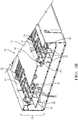
Figure 1A is a perspective view of an example electrical connector assembly with the disclosed stabilizer. -
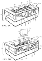
Figure 1B is a cross-sectional view through the assembly taken alongline 1B-1B inFigure 1A . -
Figure 2A is a cross-sectional view taken alongline 2A-2A inFigure 1A with the stabilizer in the pre-staged position. -
Figure 2B is a similar view to that ofFigure 2A , but with the stabilizer in an assembled connector position. -
Figure 3 is a side elevational view of the assembly and stabilizer as shown in the sectional view ofFigure 2A . -
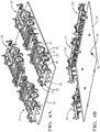
Figure 4A is a first perspective view of a printed circuit board with multiple stabilizers mounted thereto and arranged in the pre-staged position. -
Figure 4B is a second perspective view of the arrangement shown inFigure 4A . -
Figure 5 is an enlarged cross-sectional view through a post of the stabilizer that is secured to the printed circuit board. -
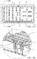
Figure 6A is a top view of the stabilizer mounted to the printed circuit board by the posts and suspended in the pre-staged position by the springs. -
Figure 6B is a cross-sectional view through the stabilizer illustrating free ends of the terminals within slots in the stabilizer. - The embodiments, examples and alternatives of the preceding paragraphs, the claims, or the following description and drawings, including any of their various aspects or respective individual features, may be taken independently or in any combination. Features described in connection with one embodiment are applicable to all embodiments, unless such features are incompatible. Like reference numbers and designations in the various drawings indicate like elements.
- An
electrical connector assembly 10 is illustrated inFigures 1A and1B . Theassembly 10 is exemplary of one configuration, although other configurations may be used with the disclosed stabilizer. Theelectrical connector assembly 10 may be a component of an electrical distribution center as shown inFigs. 1A and1B or in other embodiments may be a standalone electrical connector assembly. Theassembly 10 includes ahousing 12 having first andsecond housing portions first housing portion 14 hasmultiple windows 21 configured to each receive one or more electrical connectors (not shown). A printed circuit board (PCB) 18 is arranged within thehousing 12 and is retained by thesecond housing portion 16 by supports 19.Multiple terminals 20, typically male terminals, extend from thePCB 18 for connection with electrical connectors that are in electrical communication with various components distributed throughout the vehicle. - In the example, a
stabilizer 22 is provided within eachwindow 21. Eachstabilizer 22 includes awall 24 havingslots 26 each circumscribed by aprotrusion 28, for example. Afree end 27 of each terminal 20 is received within a correspondingslot 26. Thefree end 27 may be contained within theslot 26 or extend partially from theslot 26. Thestabilizer 22 provides support to theterminals 20 such that they do not become inadvertently bent during handling or misaligned with respect to the mating electrical connectors during the assembly process. -
Figure 2A illustrates the stabilizer at 22 in a pre-staged condition prior to installation of a mating connector and subsequent to removal of that mating connector.Figure 2B illustrates an assembled connector position in which thestabilizer 22 has been moved toward thePCB 18 in response to pushing anotherelectrical connector 33 into engagement with thestabilizer 22 to electrically connect theterminals 20 with terminals 35. - Referring to
Figures 2A-3 and6A , thewall 24 of thestabilizer 22 has spaced apart lateral edges 30 (best shown inFig. 6A ). Multiple springs 32 are configured to bias thestabilizer 22 away from thePCB 18 to the pre-staged position illustrated inFigure 2A . In one example, apost 34 next to eachlateral edge 30 is secured to thePCB 18. In the example, each post has abarb 36 received in a hole 38 (Fig. 5 ) in the PCB, which is best illustrated inFigure 3 and4B . - One of the
springs 32 extends from each of opposing sides of thepost 34 such that a pair ofsprings 32 is used to support eachlateral edge 30 with respect to itscorresponding post 34, as best shown inFigure 4A . Thesprings 32 are S-shaped, i.e. having a serpentine or sinusoidal shape. Eachspring 32 includes afirst end 44 secured to itsrespective post 34 and asecond end 46 secured to its respectivelateral edge 30. Thespring 32 includes atrough 42 extending from thefirst end 44 to a peak 40 that extends to thesecond end 46. Thehousing portion 14 includes acontour 48 that corresponds to the S-shape when thestabilizer 22 is in the pre-staged condition, as shown inFigure 3 . Thiscontour 48 maintains desired alignment and positioning of thestabilizer 22 with respect to thehousing 12 via thesprings 32. - Referring to
Figures 2A, 2B , and4A , thewall 24 supports upper andlower stops upper stop 50 is in close proximity to or in contact with an inner surface of thefirst housing 14 when thestabilizer 22 is in the pre-staged condition, as shown inFigure 2A . Eachupper stop 50 may be slideably received in aslot 51 in thefirst housing 14 to provide further stability to thestabilizer 22 during movement within thehousing 12. Thelower stop 52 is spaced from thePCB 18 in the pre-staged condition, but come in close proximity to or contact with thePCB 18 when the stabilizer is moved to the assembled connector position shown inFigure 2B . In this manner, the upper andlower stops stabilizer 22 respectively to the pre-staged position and the assembled connector position. - In operation, the electrical connector assembly is assembled by securing the
stabilizer 22 to the printedcircuit board 18 by thesprings 32. Thestabilizer 22 has awall 24 that includes aslot 26 that receives afree end 27 of an electrical terminal 20 (typically a male terminal). The wall is provided in the pre-staged position relative to thePCB 18 by thesprings 32. ThePCB 18 and thestabilizer 22 are mounted within thehousing 12. Aconnector 33 engages thewall 24 such that another terminal 35 (typically a female terminal) is aligned with theelectrical terminal 20. Thestabilizer 22 is pushed with theconnector 33 to overcome thesprings 32 and electrically couple theelectrical terminal 20 and the other terminal 35 in the assembled connector position. - The
connector 33 may be removed by pulling the connector to decouple theelectrical terminal 20 and the other terminal 35, which returns thestabilizer 22 to the pre-staged position using thesprings 32. The return of thestabilizer 22 to the pre-staged position may be limited by abutting thesprings 32 to thecontour 48 of thefirst housing 14 and/or contacting the interface of thefirst housing 14 with theupper stop 50. Movement of thestabilizer 22 to the assembled connector position may be limited by thelower stop 52 contacting thePCB 18. - It should also be understood that although a particular component arrangement is disclosed in the illustrated embodiment, other arrangements will benefit herefrom. Although particular step sequences are shown, described, and claimed, it should be understood that steps may be performed in any order, separated or combined unless otherwise indicated and will still benefit from the present invention.
- Although the different examples have specific components shown in the illustrations, embodiments of this invention are not limited to those particular combinations. It is possible to use some of the components or features from one of the examples in combination with features or components from another one of the examples.
- Although an example embodiment has been disclosed, a worker of ordinary skill in this art would recognize that certain modifications would come within the scope of the claims. For that reason, the following claims should be studied to determine their true scope and content.
Claims (15)
- An electrical connector assembly (10) comprising:an electrical terminal (20) mounted to a support structure;a stabilizer (22) having a slot (26) receiving a free end (27) of the electrical terminal (20); anda first spring (32) operatively supporting the stabilizer (22) relative to support structure, the first spring (32) biasing the stabilizer (22) away from the support structure to a pre-staged position, the first spring (32) configured to flex from the pre-staged position to an assembled connector position in which more of the free end (27) protrudes through the slot (26) than in the pre-staged position, wherein the first spring (32) extends from each of opposing sides of a first post (34) which is arranged at a first lateral edge (30) of the stabilizer (22), and second post (34) and a second spring (32) are arranged at a second lateral edge (30) of the stabilizer (22) opposite the first lateral edge (30).
- The assembly (10) of claim 1, wherein the first and second posts (34) are secured to the support structure.
- The assembly (10) of claim 2, wherein the first and second posts (34) each have a barb (36) that is received in a hole (38) in the support structure in a snap-fit relationship.
- The assembly (10) of claim 1, wherein the first and second springs (32) are S-shaped and each include a first end (44) secured to its respective post (34) and a second end (46) secured to the stabilizer (22), the first and second springs (32) each include a trough (42) extending from the first end (44) to a peak (40) that extends to the second end (46).
- The assembly (10) of claim 1, wherein the first and second springs (32) are integral with the stabilizer (22).
- The assembly (10) of claim 5, wherein the first and second lateral edges (30) of the stabilizer (22) are spaced apart from one another, wherein the first and second springs (32) are spaced apart from the first and second lateral edges (30), and wherein the first and second springs (32) are movable in a plane that is normal to the stabilizer (22).
- The assembly (10) of claim 1, wherein the support structure is a printed circuit board (18), and the electrical terminal (20) is a male terminal.
- The assembly (10) of claim 7, further comprising a housing (12), wherein the printed circuit board (18) is arranged within the housing (12).
- The assembly (10) of claim 8, wherein the housing (12) includes first and second housing portions (12), and the first housing portion (12) includes a window (21) exposing the stabilizer (22) and the male terminal, the first housing portion (12) has a contour (48) that corresponds to a spring contour of the first and second springs (32) in the pre-staged position.
- The assembly (10) of claim 9, wherein the stabilizer (22) has a stop (50) extending toward the printed circuit board (18), wherein the stop (50) is spaced a distance from the printed circuit board (18) equal to a distance between the stabilizer (22) and the printed circuit board (18) in the pre-staged position, the stop (50) configured to limit movement of the stabilizer (22) to the assembled connector position.
- The assembly (10) of claim 1, wherein the first and second posts (34) are secured to the support structure, wherein the first and second springs (32) are S-shaped, each including first end (44) secured to its respective post (34) and a second end (46) secured to the stabilizer (22), the first and second springs (32) include a trough (42) extending from the first end (44) to a peak (40) that extends to the second end (46), the support structure is a printed circuit board (18), and the electrical terminal (20) is a male terminal, wherein the assembly further comprises a housing (12) including first and second housing portions (12), wherein the printed circuit board (18) is arranged within the housing (12), and wherein the first housing portion (12) includes a window (21) exposing the stabilizer (22) and the male terminal.
- A method of assembling an electrical connector assembly (10), comprising:securing a stabilizer (22) to a printed circuit board (18) with spring elements intermediate the stabilizer (22) and the printed circuit board (18), wherein the stabilizer (22) has a wall (24) including a slot (26) that receives a free end (27) of an electrical terminal (20), and wherein the wall (24) is provided in a pre-staged position relative to the printed circuit board (18) by the spring elements; andmounting the printed circuit board (18) and stabilizer (22) within a housing (12).
- The method of claim 12, comprising a step of engaging the wall (24) with a connector (33), wherein the connector (33) has another terminal (35) aligned with the electrical terminal (20), and comprising a step of pushing the stabilizer (22) from a pre-staged position with the connector (33) to overcome a force generated by the spring elements and electrically couple the electrical terminal (20) and the another terminal (35) by moving the stabilizer (22) to an assembled connector position.
- The method of claim 12, wherein one of the spring elements extends from each of opposing sides of a post (34) which is arranged at one lateral edge (30) of the stabilizer (22), and another post (34) and another spring element is arranged at another lateral edge (30) of the stabilizer (22) opposite the one lateral edge (30), wherein the securing step includes inserting a barb (36) on each of the posts (34) into corresponding holes (38) in the printed circuit board (18) in a snap-fit relationship.
- An electrical connector assembly (10), comprising:an electrical terminal (20) mounted to a support structure;a stabilizer (22) having a slot (26) receiving a free end (27) of the electrical terminal (20); anda spring (32) operatively supporting the stabilizer (22) relative to support structure, the spring (32) biasing the stabilizer (22) away from the support structure to a pre-staged position, the spring (32) configured to flex from the pre-staged position to an assembled connector position in which more of the free end (27) protrudes through the slot (26) than in the pre-staged position.
Applications Claiming Priority (1)
| Application Number | Priority Date | Filing Date | Title |
|---|---|---|---|
| US16/722,681 US11203310B2 (en) | 2019-12-20 | 2019-12-20 | Electrical terminal stabilizer |
Publications (2)
| Publication Number | Publication Date |
|---|---|
| EP3840131A1 true EP3840131A1 (en) | 2021-06-23 |
| EP3840131B1 EP3840131B1 (en) | 2024-10-02 |
Family
ID=73747919
Family Applications (1)
| Application Number | Title | Priority Date | Filing Date |
|---|---|---|---|
| EP20212405.3A Active EP3840131B1 (en) | 2019-12-20 | 2020-12-08 | Electrical terminal stabilizer |
Country Status (3)
| Country | Link |
|---|---|
| US (1) | US11203310B2 (en) |
| EP (1) | EP3840131B1 (en) |
| CN (1) | CN113013655B (en) |
Citations (4)
| Publication number | Priority date | Publication date | Assignee | Title |
|---|---|---|---|---|
| JPH07282895A (en) * | 1994-04-08 | 1995-10-27 | Hirose Electric Co Ltd | Electrical connector |
| US20110294311A1 (en) * | 2010-05-26 | 2011-12-01 | Delphi Technologies, Inc. | Electrical distribution center assembly |
| EP2819248A1 (en) * | 2013-06-28 | 2014-12-31 | Delphi Technologies, Inc. | Electrical connector with integrated moveable terminal stabilizer |
| EP3399597A2 (en) * | 2017-04-14 | 2018-11-07 | Amphenol Corporation | Float electrical connector for interconnecting printed circuit boards and method thereof |
Family Cites Families (12)
| Publication number | Priority date | Publication date | Assignee | Title |
|---|---|---|---|---|
| JPH06267607A (en) * | 1993-03-09 | 1994-09-22 | Sumitomo Wiring Syst Ltd | Connector |
| US5466164A (en) * | 1993-03-09 | 1995-11-14 | Sumitomo Wiring Systems, Ltd. | Connector having a protective hood |
| US6761568B2 (en) | 2001-02-27 | 2004-07-13 | Delphi Technologies, Inc. | Electrical connector assembly |
| US6422881B1 (en) * | 2001-02-27 | 2002-07-23 | Delphi Technologies, Inc. | Electrical connector having a blade stabilizer |
| US6846191B2 (en) | 2003-01-24 | 2005-01-25 | Delphi Technologies, Inc. | Electrical connector assembly |
| FR2864357A1 (en) | 2003-12-19 | 2005-06-24 | Framatome Connectors Int | Electrical connector device, has stop unit opposing manipulation of locking device from releasing position to locking position, and rod supporting against corresponding breaker arm if contacts are partly inserted in socket |
| US7179136B1 (en) | 2006-09-19 | 2007-02-20 | Delphi Technologies, Inc. | Electrical connector |
| US7670177B2 (en) * | 2008-06-17 | 2010-03-02 | Tyco Electronics Corporation | Electrical connector having floating alignment member |
| EP2321878B1 (en) | 2008-08-06 | 2015-06-03 | Delphi International Operations Luxembourg S.à r.l. | Electrical connector with terminal protection and centering device |
| US8038455B1 (en) | 2010-10-28 | 2011-10-18 | Delphi Technologies, Inc. | Connector assembly having retractable stabilizer including inward flexing securing member |
| US8926344B2 (en) | 2013-01-16 | 2015-01-06 | Delphi Technologies, Inc. | Electrical distribution center assembly having a terminal stabilizer plate |
| US10236629B2 (en) * | 2017-05-08 | 2019-03-19 | Aptiv Technologies Limited | Electrical connector with retractable terminal-stabilizer |
-
2019
- 2019-12-20 US US16/722,681 patent/US11203310B2/en active Active
-
2020
- 2020-12-08 EP EP20212405.3A patent/EP3840131B1/en active Active
- 2020-12-18 CN CN202011507635.2A patent/CN113013655B/en active Active
Patent Citations (4)
| Publication number | Priority date | Publication date | Assignee | Title |
|---|---|---|---|---|
| JPH07282895A (en) * | 1994-04-08 | 1995-10-27 | Hirose Electric Co Ltd | Electrical connector |
| US20110294311A1 (en) * | 2010-05-26 | 2011-12-01 | Delphi Technologies, Inc. | Electrical distribution center assembly |
| EP2819248A1 (en) * | 2013-06-28 | 2014-12-31 | Delphi Technologies, Inc. | Electrical connector with integrated moveable terminal stabilizer |
| EP3399597A2 (en) * | 2017-04-14 | 2018-11-07 | Amphenol Corporation | Float electrical connector for interconnecting printed circuit boards and method thereof |
Also Published As
| Publication number | Publication date |
|---|---|
| CN113013655A (en) | 2021-06-22 |
| US11203310B2 (en) | 2021-12-21 |
| EP3840131B1 (en) | 2024-10-02 |
| US20210188202A1 (en) | 2021-06-24 |
| CN113013655B (en) | 2023-04-07 |
Similar Documents
| Publication | Publication Date | Title |
|---|---|---|
| JP7815402B2 (en) | Floating Socket Connector | |
| EP0546804B1 (en) | Electrical connector | |
| EP0280449B1 (en) | Surface mount electrical connector | |
| US7367816B2 (en) | Board-to-board connectors | |
| KR910003908Y1 (en) | Electrical connector | |
| CN104221227B (en) | Wire-to-board connector | |
| HK1000396B (en) | Electrical connector | |
| JP2002033147A (en) | Electric connector | |
| JP2006059821A (en) | Printed circuit board surface-mounted device | |
| KR20210069553A (en) | Connector assembly | |
| US6866552B2 (en) | Electrical connector with a terminal pin alignment plate | |
| CN111373608B (en) | Electrical connector | |
| US6135816A (en) | Electrical connector having an improved construction for fixing shield plates to a receptacle connector | |
| EP0191539A2 (en) | Electrical connecting terminal for a connector | |
| WO2017203379A1 (en) | Poke-in electrical connector | |
| US4184730A (en) | Electrical building blocks incorporating an angular adapter and a process to manufacture the same | |
| CA1075788A (en) | Printed circuit board edge connector | |
| US11203310B2 (en) | Electrical terminal stabilizer | |
| US6824425B2 (en) | Electrical connector having improved retention structure | |
| US6994577B2 (en) | Panel mounted electrical connector system | |
| KR101611781B1 (en) | Connection terminal and connector using same | |
| EP0385019B1 (en) | Electrical connector having preloaded terminals and method of manufacture | |
| KR20170045627A (en) | Board to board connector | |
| JP2008084878A (en) | Manufacturing method of electrical connector having fixing metal fitting | |
| CN111628317B (en) | A board-to-board connector |
Legal Events
| Date | Code | Title | Description |
|---|---|---|---|
| PUAI | Public reference made under article 153(3) epc to a published international application that has entered the european phase |
Free format text: ORIGINAL CODE: 0009012 |
|
| STAA | Information on the status of an ep patent application or granted ep patent |
Free format text: STATUS: THE APPLICATION HAS BEEN PUBLISHED |
|
| AK | Designated contracting states |
Kind code of ref document: A1 Designated state(s): AL AT BE BG CH CY CZ DE DK EE ES FI FR GB GR HR HU IE IS IT LI LT LU LV MC MK MT NL NO PL PT RO RS SE SI SK SM TR |
|
| STAA | Information on the status of an ep patent application or granted ep patent |
Free format text: STATUS: REQUEST FOR EXAMINATION WAS MADE |
|
| 17P | Request for examination filed |
Effective date: 20211221 |
|
| RBV | Designated contracting states (corrected) |
Designated state(s): AL AT BE BG CH CY CZ DE DK EE ES FI FR GB GR HR HU IE IS IT LI LT LU LV MC MK MT NL NO PL PT RO RS SE SI SK SM TR |
|
| STAA | Information on the status of an ep patent application or granted ep patent |
Free format text: STATUS: EXAMINATION IS IN PROGRESS |
|
| 17Q | First examination report despatched |
Effective date: 20230130 |
|
| RAP3 | Party data changed (applicant data changed or rights of an application transferred) |
Owner name: APTIV TECHNOLOGIES LIMITED |
|
| GRAP | Despatch of communication of intention to grant a patent |
Free format text: ORIGINAL CODE: EPIDOSNIGR1 |
|
| STAA | Information on the status of an ep patent application or granted ep patent |
Free format text: STATUS: GRANT OF PATENT IS INTENDED |
|
| RAP1 | Party data changed (applicant data changed or rights of an application transferred) |
Owner name: APTIV TECHNOLOGIES AG |
|
| INTG | Intention to grant announced |
Effective date: 20240513 |
|
| GRAS | Grant fee paid |
Free format text: ORIGINAL CODE: EPIDOSNIGR3 |
|
| GRAA | (expected) grant |
Free format text: ORIGINAL CODE: 0009210 |
|
| STAA | Information on the status of an ep patent application or granted ep patent |
Free format text: STATUS: THE PATENT HAS BEEN GRANTED |
|
| RAP3 | Party data changed (applicant data changed or rights of an application transferred) |
Owner name: APTIV TECHNOLOGIES AG |
|
| AK | Designated contracting states |
Kind code of ref document: B1 Designated state(s): AL AT BE BG CH CY CZ DE DK EE ES FI FR GB GR HR HU IE IS IT LI LT LU LV MC MK MT NL NO PL PT RO RS SE SI SK SM TR |
|
| REG | Reference to a national code |
Ref country code: GB Ref legal event code: FG4D |
|
| REG | Reference to a national code |
Ref country code: CH Ref legal event code: EP |
|
| REG | Reference to a national code |
Ref country code: DE Ref legal event code: R096 Ref document number: 602020038637 Country of ref document: DE |
|
| REG | Reference to a national code |
Ref country code: IE Ref legal event code: FG4D |
|
| P01 | Opt-out of the competence of the unified patent court (upc) registered |
Free format text: CASE NUMBER: APP_55773/2024 Effective date: 20241011 |
|
| REG | Reference to a national code |
Ref country code: LT Ref legal event code: MG9D |
|
| REG | Reference to a national code |
Ref country code: NL Ref legal event code: MP Effective date: 20241002 |
|
| REG | Reference to a national code |
Ref country code: AT Ref legal event code: MK05 Ref document number: 1729150 Country of ref document: AT Kind code of ref document: T Effective date: 20241002 |
|
| PG25 | Lapsed in a contracting state [announced via postgrant information from national office to epo] |
Ref country code: NL Free format text: LAPSE BECAUSE OF FAILURE TO SUBMIT A TRANSLATION OF THE DESCRIPTION OR TO PAY THE FEE WITHIN THE PRESCRIBED TIME-LIMIT Effective date: 20241002 |
|
| PG25 | Lapsed in a contracting state [announced via postgrant information from national office to epo] |
Ref country code: NL Free format text: LAPSE BECAUSE OF FAILURE TO SUBMIT A TRANSLATION OF THE DESCRIPTION OR TO PAY THE FEE WITHIN THE PRESCRIBED TIME-LIMIT Effective date: 20241002 |
|
| PG25 | Lapsed in a contracting state [announced via postgrant information from national office to epo] |
Ref country code: PT Free format text: LAPSE BECAUSE OF FAILURE TO SUBMIT A TRANSLATION OF THE DESCRIPTION OR TO PAY THE FEE WITHIN THE PRESCRIBED TIME-LIMIT Effective date: 20250203 Ref country code: IS Free format text: LAPSE BECAUSE OF FAILURE TO SUBMIT A TRANSLATION OF THE DESCRIPTION OR TO PAY THE FEE WITHIN THE PRESCRIBED TIME-LIMIT Effective date: 20250202 Ref country code: HR Free format text: LAPSE BECAUSE OF FAILURE TO SUBMIT A TRANSLATION OF THE DESCRIPTION OR TO PAY THE FEE WITHIN THE PRESCRIBED TIME-LIMIT Effective date: 20241002 |
|
| PG25 | Lapsed in a contracting state [announced via postgrant information from national office to epo] |
Ref country code: FI Free format text: LAPSE BECAUSE OF FAILURE TO SUBMIT A TRANSLATION OF THE DESCRIPTION OR TO PAY THE FEE WITHIN THE PRESCRIBED TIME-LIMIT Effective date: 20241002 |
|
| PG25 | Lapsed in a contracting state [announced via postgrant information from national office to epo] |
Ref country code: BG Free format text: LAPSE BECAUSE OF FAILURE TO SUBMIT A TRANSLATION OF THE DESCRIPTION OR TO PAY THE FEE WITHIN THE PRESCRIBED TIME-LIMIT Effective date: 20241002 |
|
| PG25 | Lapsed in a contracting state [announced via postgrant information from national office to epo] |
Ref country code: ES Free format text: LAPSE BECAUSE OF FAILURE TO SUBMIT A TRANSLATION OF THE DESCRIPTION OR TO PAY THE FEE WITHIN THE PRESCRIBED TIME-LIMIT Effective date: 20241002 |
|
| PG25 | Lapsed in a contracting state [announced via postgrant information from national office to epo] |
Ref country code: NO Free format text: LAPSE BECAUSE OF FAILURE TO SUBMIT A TRANSLATION OF THE DESCRIPTION OR TO PAY THE FEE WITHIN THE PRESCRIBED TIME-LIMIT Effective date: 20250102 |
|
| PG25 | Lapsed in a contracting state [announced via postgrant information from national office to epo] |
Ref country code: AT Free format text: LAPSE BECAUSE OF FAILURE TO SUBMIT A TRANSLATION OF THE DESCRIPTION OR TO PAY THE FEE WITHIN THE PRESCRIBED TIME-LIMIT Effective date: 20241002 Ref country code: GR Free format text: LAPSE BECAUSE OF FAILURE TO SUBMIT A TRANSLATION OF THE DESCRIPTION OR TO PAY THE FEE WITHIN THE PRESCRIBED TIME-LIMIT Effective date: 20250103 Ref country code: LV Free format text: LAPSE BECAUSE OF FAILURE TO SUBMIT A TRANSLATION OF THE DESCRIPTION OR TO PAY THE FEE WITHIN THE PRESCRIBED TIME-LIMIT Effective date: 20241002 |
|
| PG25 | Lapsed in a contracting state [announced via postgrant information from national office to epo] |
Ref country code: CZ Free format text: LAPSE BECAUSE OF FAILURE TO SUBMIT A TRANSLATION OF THE DESCRIPTION OR TO PAY THE FEE WITHIN THE PRESCRIBED TIME-LIMIT Effective date: 20241002 Ref country code: PL Free format text: LAPSE BECAUSE OF FAILURE TO SUBMIT A TRANSLATION OF THE DESCRIPTION OR TO PAY THE FEE WITHIN THE PRESCRIBED TIME-LIMIT Effective date: 20241002 |
|
| PG25 | Lapsed in a contracting state [announced via postgrant information from national office to epo] |
Ref country code: RS Free format text: LAPSE BECAUSE OF FAILURE TO SUBMIT A TRANSLATION OF THE DESCRIPTION OR TO PAY THE FEE WITHIN THE PRESCRIBED TIME-LIMIT Effective date: 20250102 |
|
| PG25 | Lapsed in a contracting state [announced via postgrant information from national office to epo] |
Ref country code: SM Free format text: LAPSE BECAUSE OF FAILURE TO SUBMIT A TRANSLATION OF THE DESCRIPTION OR TO PAY THE FEE WITHIN THE PRESCRIBED TIME-LIMIT Effective date: 20241002 |
|
| REG | Reference to a national code |
Ref country code: DE Ref legal event code: R097 Ref document number: 602020038637 Country of ref document: DE |
|
| PG25 | Lapsed in a contracting state [announced via postgrant information from national office to epo] |
Ref country code: MC Free format text: LAPSE BECAUSE OF FAILURE TO SUBMIT A TRANSLATION OF THE DESCRIPTION OR TO PAY THE FEE WITHIN THE PRESCRIBED TIME-LIMIT Effective date: 20241002 |
|
| PG25 | Lapsed in a contracting state [announced via postgrant information from national office to epo] |
Ref country code: DK Free format text: LAPSE BECAUSE OF FAILURE TO SUBMIT A TRANSLATION OF THE DESCRIPTION OR TO PAY THE FEE WITHIN THE PRESCRIBED TIME-LIMIT Effective date: 20241002 |
|
| PG25 | Lapsed in a contracting state [announced via postgrant information from national office to epo] |
Ref country code: EE Free format text: LAPSE BECAUSE OF FAILURE TO SUBMIT A TRANSLATION OF THE DESCRIPTION OR TO PAY THE FEE WITHIN THE PRESCRIBED TIME-LIMIT Effective date: 20241002 |
|
| PG25 | Lapsed in a contracting state [announced via postgrant information from national office to epo] |
Ref country code: RO Free format text: LAPSE BECAUSE OF FAILURE TO SUBMIT A TRANSLATION OF THE DESCRIPTION OR TO PAY THE FEE WITHIN THE PRESCRIBED TIME-LIMIT Effective date: 20241002 |
|
| PG25 | Lapsed in a contracting state [announced via postgrant information from national office to epo] |
Ref country code: SK Free format text: LAPSE BECAUSE OF FAILURE TO SUBMIT A TRANSLATION OF THE DESCRIPTION OR TO PAY THE FEE WITHIN THE PRESCRIBED TIME-LIMIT Effective date: 20241002 |
|
| PG25 | Lapsed in a contracting state [announced via postgrant information from national office to epo] |
Ref country code: IT Free format text: LAPSE BECAUSE OF FAILURE TO SUBMIT A TRANSLATION OF THE DESCRIPTION OR TO PAY THE FEE WITHIN THE PRESCRIBED TIME-LIMIT Effective date: 20241002 |
|
| REG | Reference to a national code |
Ref country code: CH Ref legal event code: PL |
|
| PLBE | No opposition filed within time limit |
Free format text: ORIGINAL CODE: 0009261 |
|
| STAA | Information on the status of an ep patent application or granted ep patent |
Free format text: STATUS: NO OPPOSITION FILED WITHIN TIME LIMIT |
|
| PG25 | Lapsed in a contracting state [announced via postgrant information from national office to epo] |
Ref country code: LU Free format text: LAPSE BECAUSE OF NON-PAYMENT OF DUE FEES Effective date: 20241208 |
|
| PG25 | Lapsed in a contracting state [announced via postgrant information from national office to epo] |
Ref country code: SE Free format text: LAPSE BECAUSE OF FAILURE TO SUBMIT A TRANSLATION OF THE DESCRIPTION OR TO PAY THE FEE WITHIN THE PRESCRIBED TIME-LIMIT Effective date: 20241002 |
|
| 26N | No opposition filed |
Effective date: 20250703 |
|
| REG | Reference to a national code |
Ref country code: BE Ref legal event code: MM Effective date: 20241231 |
|
| PG25 | Lapsed in a contracting state [announced via postgrant information from national office to epo] |
Ref country code: BE Free format text: LAPSE BECAUSE OF NON-PAYMENT OF DUE FEES Effective date: 20241231 |
|
| PG25 | Lapsed in a contracting state [announced via postgrant information from national office to epo] |
Ref country code: CH Free format text: LAPSE BECAUSE OF NON-PAYMENT OF DUE FEES Effective date: 20241231 |
|
| PG25 | Lapsed in a contracting state [announced via postgrant information from national office to epo] |
Ref country code: IE Free format text: LAPSE BECAUSE OF NON-PAYMENT OF DUE FEES Effective date: 20241208 |
|
| PGFP | Annual fee paid to national office [announced via postgrant information from national office to epo] |
Ref country code: DE Payment date: 20251117 Year of fee payment: 6 |
|
| PGFP | Annual fee paid to national office [announced via postgrant information from national office to epo] |
Ref country code: GB Payment date: 20251107 Year of fee payment: 6 |
|
| PGFP | Annual fee paid to national office [announced via postgrant information from national office to epo] |
Ref country code: FR Payment date: 20251112 Year of fee payment: 6 |