EP3839722A1 - Micro frontends with model-based state - Google Patents
Micro frontends with model-based state Download PDFInfo
- Publication number
- EP3839722A1 EP3839722A1 EP20215235.1A EP20215235A EP3839722A1 EP 3839722 A1 EP3839722 A1 EP 3839722A1 EP 20215235 A EP20215235 A EP 20215235A EP 3839722 A1 EP3839722 A1 EP 3839722A1
- Authority
- EP
- European Patent Office
- Prior art keywords
- user interface
- micro
- frontend
- building block
- model
- Prior art date
- Legal status (The legal status is an assumption and is not a legal conclusion. Google has not performed a legal analysis and makes no representation as to the accuracy of the status listed.)
- Granted
Links
Images





Classifications
-
- G—PHYSICS
- G06—COMPUTING OR CALCULATING; COUNTING
- G06F—ELECTRIC DIGITAL DATA PROCESSING
- G06F30/00—Computer-aided design [CAD]
- G06F30/20—Design optimisation, verification or simulation
-
- G—PHYSICS
- G06—COMPUTING OR CALCULATING; COUNTING
- G06F—ELECTRIC DIGITAL DATA PROCESSING
- G06F3/00—Input arrangements for transferring data to be processed into a form capable of being handled by the computer; Output arrangements for transferring data from processing unit to output unit, e.g. interface arrangements
- G06F3/01—Input arrangements or combined input and output arrangements for interaction between user and computer
- G06F3/048—Interaction techniques based on graphical user interfaces [GUI]
- G06F3/0481—Interaction techniques based on graphical user interfaces [GUI] based on specific properties of the displayed interaction object or a metaphor-based environment, e.g. interaction with desktop elements like windows or icons, or assisted by a cursor's changing behaviour or appearance
- G06F3/0482—Interaction with lists of selectable items, e.g. menus
-
- G—PHYSICS
- G06—COMPUTING OR CALCULATING; COUNTING
- G06F—ELECTRIC DIGITAL DATA PROCESSING
- G06F3/00—Input arrangements for transferring data to be processed into a form capable of being handled by the computer; Output arrangements for transferring data from processing unit to output unit, e.g. interface arrangements
- G06F3/01—Input arrangements or combined input and output arrangements for interaction between user and computer
- G06F3/048—Interaction techniques based on graphical user interfaces [GUI]
- G06F3/0481—Interaction techniques based on graphical user interfaces [GUI] based on specific properties of the displayed interaction object or a metaphor-based environment, e.g. interaction with desktop elements like windows or icons, or assisted by a cursor's changing behaviour or appearance
- G06F3/0483—Interaction with page-structured environments, e.g. book metaphor
-
- G—PHYSICS
- G06—COMPUTING OR CALCULATING; COUNTING
- G06F—ELECTRIC DIGITAL DATA PROCESSING
- G06F8/00—Arrangements for software engineering
- G06F8/30—Creation or generation of source code
- G06F8/34—Graphical or visual programming
-
- G—PHYSICS
- G06—COMPUTING OR CALCULATING; COUNTING
- G06F—ELECTRIC DIGITAL DATA PROCESSING
- G06F8/00—Arrangements for software engineering
- G06F8/30—Creation or generation of source code
- G06F8/35—Creation or generation of source code model driven
-
- G—PHYSICS
- G06—COMPUTING OR CALCULATING; COUNTING
- G06F—ELECTRIC DIGITAL DATA PROCESSING
- G06F3/00—Input arrangements for transferring data to be processed into a form capable of being handled by the computer; Output arrangements for transferring data from processing unit to output unit, e.g. interface arrangements
- G06F3/01—Input arrangements or combined input and output arrangements for interaction between user and computer
- G06F3/048—Interaction techniques based on graphical user interfaces [GUI]
-
- G—PHYSICS
- G06—COMPUTING OR CALCULATING; COUNTING
- G06F—ELECTRIC DIGITAL DATA PROCESSING
- G06F3/00—Input arrangements for transferring data to be processed into a form capable of being handled by the computer; Output arrangements for transferring data from processing unit to output unit, e.g. interface arrangements
- G06F3/01—Input arrangements or combined input and output arrangements for interaction between user and computer
- G06F3/048—Interaction techniques based on graphical user interfaces [GUI]
- G06F3/0484—Interaction techniques based on graphical user interfaces [GUI] for the control of specific functions or operations, e.g. selecting or manipulating an object, an image or a displayed text element, setting a parameter value or selecting a range
- G06F3/0486—Drag-and-drop
Definitions
- This specification relates to a computing architecture that enables users to develop applications using building blocks that include micro frontends.
- microservice architecture that structures applications as a group of services that can each be reused in other applications.
- micro frontend architecture that structures user interfaces as a group of frontend components that can be reused in other user interfaces of other applications.
- a micro frontend can be in the form of one or more frontend components that can be included in a page, e.g., a web page or application page.
- Each micro frontend can have its own independent backend, e.g., in the form of a microservice, that is part of a building block, e.g., a business component, that includes the micro frontend.
- independent teams can develop building blocks that can be inserted into multiple user interfaces, e.g., multiple pages.
- the backend for a micro frontend can be connected to the user interface components of the micro fronted using declarative bindings, e.g., using JavaScript Object Notation (JSON).
- JSON JavaScript Object Notation
- the use of declarative bindings enables the user interface components to be decoupled from the physical backend implementation and enables decoupling from specific user interface technologies. In this way, the user interface can optimize the rendering on specific user interface technologies.
- the micro frontends of a user interface can also be connected using declarative bindings that enable the micro frontends to communicate, e.g., using messages that include actions.
- a micro frontend can include a globally-managed model-based state that is changed based on actions received from the user interface or another micro frontend.
- a micro frontend can include a global store, which can be implemented on the frontend, that manages the state for the micro frontend.
- the state can represent the micro frontend's model.
- the micro frontend receives an action, e.g., based on user interaction with the user interface component or an action received from another micro frontend, the store can send the action to the backend.
- the backend can include one or more reducers that generates an updated model, e.g., without changing the model, based on the action and the previous model and sends the updated model to the store.
- an immutable model is threaded through the reducer function(s), which yields the new, immutable version of the model for the store.
- This model-based approach fits well as a distributed and concurrent computation paradigm at a larger scale where actors achieve a distrusted computation by exchanging messages and encapsulating their state.
- This also enables business components, which can be a combination of one or more micro frontends with a corresponding backend, to be location transparent, which means that a single page in an application can be composed by business components running on distinct servers.
- the state management enables stateless computation to be predictable, parallelized, and horizontally scalable.
- one innovative aspect of the subject matter described in this specification can be embodied in methods that include providing a configuration user interface that enables a user to select and arrange building block user interface elements in a layout for a page; receiving, from the configuration user interface, data specifying a layout of one or more building block user interface elements that each include a micro frontend and corresponding backend logic, wherein: each micro frontend includes one or more user interface components and a store that manages a model that represents a state of the one or more user interface components of the micro frontend; and the corresponding backend for each micro frontend includes a function that updates the model of the micro frontend based on a previous model of the micro frontend and an action; and generating user interface data that, when processed by an application, causes the application to generate a user interface that presents the one or more user interface components of each of the one or more building block user interface elements in the layout specified by the received data.
- Other implementations of this aspect include corresponding systems, apparatus, and computer programs, configured to perform the actions of the methods, encoded
- Some aspects can include receiving data specifying that a first building block user interface element is a subscriber to messages generated by a second building block user interface element and generating a declarative binding between the first building block user interface element and the second building block user interface element.
- the backend of each building block user interface element includes one or more reducer functions.
- a given user interface component of each building block user interface element can include an action that is bound to a corresponding reducer function of the backend of the building block user interface element.
- the store of each micro frontend can be configured to send a current model maintained by the store and action data specifying a detected action to the corresponding reducer function in response to detecting the action.
- Each reducer function can be configured to generate an updated model based on the received current model and action data and provide the updated model to the store.
- each of the one or more user interface components is bound to a respective attribute of the model. Some aspects can include updating the one or more user interface components in response to receiving an updated model that includes updated attributes. Some aspects can include receiving data defining custom business logic for the user interface.
- the subject matter described in this specification can be implemented in particular embodiments and may result in one or more of the following advantages.
- Using the actor-like paradigm for communication between business components that is based on asynchronous message passing not only enables local transparency - e.g., different business components on a single page can run on physically different back-ends - but also enables temporal decoupling such that a receiving business component does not need to be in any way active and listening for messages. Instead, the business component is activated by the architecture on demand. In addition, the sending business component does not need to wait for the message to be processed, both of which enables better resource utilization and more efficient communication.
- model-based state, declarative configuration and composition, and vertical reuse and encapsulation provided by business components and other building blocks described in this document allows component and toolkit developers to safely define business logic within well-defined physical and logical perimeters, enables app developers to leverage a substantial amount of pre-built, tested, and vertical building blocks that speak their same business language, and lets designers draw from the thinking and user experience that inspired and were infused in the whole platform, from the most basic user interface components to declarative layouts and page navigation.
- the architecture can be used to enable developers to quickly create reusable applications with no-code and/or low-code approaches and to build and allow the building of reusable vertical toolkits that contain a set of building blocks, e.g., a set of building blocks for a particular team of developers that are typical for that team's business context. Using such building blocks reduces errors introduced by regenerating similar micro frontends for each application, rather than using pre-tested building blocks.
- FIG. 1 is a block diagram of an example environment 100 in which an application development system 110 enables a user to develop an application using building block user interface elements ("building blocks") that include micro frontends.
- the application development system 110 includes a frontend configuration engine 113, a backend configuration engine 115, and a building blocks data storage device 117 that store building blocks.
- the frontend configuration engine 113 enables users, e.g., application developers, to generate a frontend of an application, e.g., one or more pages or other user interfaces of the application using a configuration user interface 120.
- the frontend configuration engine 113 can enable a user to generate web pages, application pages of native applications developed for particular platforms or devices, or other computer-generated user interfaces.
- the application development system 110 will be described largely in terms of "pages,” which can refer to any of these types of user interfaces.
- a user can create a page by adding building blocks to an editor page 127 of the user configuration interface 120.
- the configuration user interface 120 includes a menu 126 of configured building blocks that the user can select and place in the editor page 127 of the configuration user interface 120.
- a user can drag and drop a building block from the menu 126 to the editor page 127.
- the user can arrange the building blocks within the editor page 127 to configure the layout for the user interface.
- the location of a building block within the user interface can represent the actual location of a user interface component generated and presented within the page when the configured page is presented on a user device, e.g., when a configured web page is presented in a web browser running on a user device.
- Each building block can include a micro frontend and a corresponding independent backend component.
- a micro frontend can be in the form of one or more frontend components that are presented within a page that includes the micro front end.
- a micro frontend can include one or more images (or image presentation components in which an image is selected and presented), buttons, icons, slider controls, selector lists, dropdown menus, etc.
- the backend of a building block can be in the form of a microservice or other business logic.
- the backend of a building block includes one or more functions, e.g., one or more reducer functions, that update a model of the frontend based on data specifying an action received from the micro frontend.
- the building blocks can have different types of backends, e.g., with logic or code that runs on different platforms.
- the backend of a building block for a button may be a microservice programmed using a first programming language that runs on a first server and the backend of a building block for presenting images may be a microservice programmed using a second programming language different from the first programming language and that runs on a second server different from the first server.
- independent teams can develop building blocks that can be inserted into multiple user interfaces, e.g., multiple pages.
- the backend for a micro frontend can be connected to the user interface components of the micro fronted using declarative bindings, e.g., using JSON.
- the micro frontends of a user interface can also be connected to each other using declarative bindings that enable the micro frontends to communicate, e.g., using messages that include actions, as described in more detail below.
- a micro frontend of a building block can include a globally-managed model-based state that is changed based on actions.
- the action can be in the form of a user interaction with the frontend component(s) of the micro frontend, a message from another micro frontend, or a message from the page that includes the micro frontend.
- Each micro frontend can include a global store, which can be implemented on the frontend (e.g., as code of a web page or native application), that maintains and manages the state for the micro frontend.
- the state can represent the micro frontend's model.
- the store can send data specifying the action to the backend corresponding to the micro frontend.
- the backend can include one or more functions, e.g., reducer functions, that receives the model and the data specifying the action and generates an updated model based on the action and the received model.
- the reducer function(s) can generate the updated model without changing the model itself.
- the model describes the state of the user interface components of the micro frontend.
- the model defines how the user interface elements are displayed and how actions (e.g., user interactions with the user interface elements, another micro frontend, or another user interface component) impact the business logic and thereby updates the user interface components of the micro frontend. For example, in a page where devices are selected among a list of possible devices, a user interface component of the micro frontend would need to represent the list (e.g., in the form of a drop down menu) and enable the user viewing the page to select one or more of the devices from the list.
- One example way of implementing this would be a model that includes a list of devices (e.g., their stock-keeping units (SKUs)) represented as strings and a list among this list which have been selected by the user which may also be represented as strings.
- the relationship between the list of devices displayed by the user interface component and the business logic of the backend can be established using declarative bindings on the page configuration. For example, if JSON is used, this relationship can be specified as "choices: $ ⁇ possibleDevices ⁇ ".
- the correlation between the user selecting the devices and the corresponding population of these values can be implemented by the inner workings on the client, driven by the bindings configuration for the page.
- the correlation can be defined by "selected: $ ⁇ selectedDevices ⁇ ", where "selectedDevices" is the name of the model field in the model of the building block.
- selectedDevices is the name of the model field in the model of the building block.
- the model maintains the current state of the micro frontend by specifying the devices included in the list of devices and the currently selected devices using two model parameters, the "possibleDevices" list and the "selectedDevices” list.
- the micro frontend can pass the current model to a reducer function on the backend along with data specifying the action.
- the reducer function can generate an updated model based on the action and provide the updated model back to the micro frontend and the micro frontend can update the user interface components based on the action.
- the micro front end can send the model that specifies the current state of both lists and data specifying that "Dev43" has been selected.
- the backend can use a reducer function to update the model.
- This reducer function can be configured to update the "selectedDevices" list to specify the current list of selected devices, e.g., to include "Dev42" and "Dev43" in response to the user's selection of "Dev43.”
- the backend can provide the updated model including the two lists to the micro frontend.
- the micro frontend can use the updated lists to update the drop down menu to show that both "Dev42" and "Dev43" have been selected.
- the building blocks can include multiple types of building blocks.
- One type of building block is an individual user interface component, such as a button, icon, graphic, etc.
- the user interface component can include a single frontend component in the form of a micro frontend, a corresponding backend, and a model for the frontend component. These user interface components can be context and application agnostic.
- a card can include groups of user interface component building blocks organized into a layout. For example, a user can define an arrangement of multiple user interface components that can be included in a page or other user interface. The user can also configure the communications between the user interface components in a similar way as a user would configure communications between individual building blocks, as described below. In this way, a user can place a card on a page and the card will be displayed on that page in the layout defined by the user. In addition, the user would not have to configure the layout or communication between the user interface components of the card. This makes it easier and more efficient for groups or layouts of user interface components that will be reused with different pages.
- a business component is a set of user interface component building blocks and/or cards in a particular layout, e.g., a user-defined layout, and backend business logic.
- the backend business logic can include one or more reducer functions that change the state of a micro frontend based on a previous state of the micro frontend and an action.
- a map business component can present a map of a geographic area. If a user zooms in or out of the map (e.g., the action), the reducer function can update the map based on the geographic area previously shown by the map (e.g., the previous state) and the zoom action.
- the business components can be context-aware and application-agnostic. For example, a business component can forecast metrics and can be used in multiple different applications.
- a page is a layout of one or more user interface component building blocks, one or more cards, and/or one or more business components. Like the cards and business components, the layout of the page can be defined by a user.
- a page can also include backend business logic, e.g., application-specific business logic, in the form of one or more reducer functions.
- Each business component can also have its own backend business logic, as described above.
- the page and each business component on the page can have its own independent backend business logic that the business component or page is connected to using declarative bindings, e.g., JSON declarative bindings.
- a page can be context-aware and application-aware.
- a page can be a custom web application.
- a page can include a forecasting reporting dashboard for a particular web application.
- the pages can interact with one another.
- pages may interact with one another using navigation rather than subscriptions.
- one page can pass parameters to another page during navigation.
- the parameters can be Uniform Resource Locator (URL) parameters that are passed to the next page when the web browser navigates from the previous page to the next page.
- URL Uniform Resource Locator
- the business components are building blocks that have the same frontend and backend aspects for each user interface in which they are included.
- the application development system 110 may not allow users to directly modify the frontend or backend aspects (e.g., the reducer functions) of the building blocks.
- the pages can enable the configuration of business components indirectly by including business logic in the page that can send messages to and receive message from the business components or other building blocks.
- a user that develops a business component or other type of building block can include configurable options that allow users to configure some aspects of the frontend and/or backend aspects of the business component or other type of building block.
- the user interface components, cards, business components and/or pages can be configured via JSON, making them editor friendly.
- the JSON elements can be extracted and re-used in other components, making the elements reusable with little or no changes to the code.
- the JSON elements also enable declarative bindings between user interface components, cards, and business components.
- the business components can include micro frontends on the user interface and business logic, e.g., vertical business logic, on the backend.
- business logic e.g., vertical business logic
- the business components include both the frontend and backend functionality that can simply be dragged and dropped into the configuration of a page without modifying code.
- Having the business logic on the backend allows for better security relative to having business logic on the frontend and also allows for a polyglot architecture in which the backends can be configured using different programming languages and software platforms.
- Users can generate building blocks, test the building blocks, and add the building blocks to the building blocks building blocks data storage device 117.
- the application development system 110 can add the building blocks to the building blocks menu 126.
- a user can generate a page by adding building blocks to the editor page 127, e.g., by dragging and dropping the building blocks from the building blocks menu 126.
- the user can configure the micro frontends on a page to communicate with one another and/or with business logic of the page itself. For example, the user can connect multiple building blocks together using lines within the editor page 127 so that the building blocks can communicate with each other.
- the frontend configuration engine 113 can generate declarative bindings between the micro frontends of the building blocks, which can subscribe a micro frontend to receive messages from another micro frontend.
- the frontend configuration engine 113 can generate the connections between micro frontends automatically, e.g., based on preconfigured communications for groups of one or more micro frontends.
- one building block may allow a user to make a selection and a corresponding building block can present content based on the selection.
- the corresponding building block may be preconfigured to subscribe to message sent by the one building block.
- the user has placed two sample business components on the editor page 127.
- the sample business components are a "Device List” business component 122 and a “Device Indicator” business component 124.
- the "Device List” business component 122 When presented on a page, the "Device List” business component 122 enables end users to select devices from a list of devices and, in response, sends messages of type "OnDeviceSelect" to any business component or other building block on the page that are subscribed to receive "OnDeviceSelect messages, or to the page that includes the "Device List” business component 122.
- the "OnDeviceSelect” message indicates the set of devices that were selected by the end user in the "Device List” business component 122.
- the "Device List” business component 122 can send a message to the subscribed building blocks and/or to the business logic of the web page or application page. This message can indicate that "Device 1" has been selected or can indicate all of the devices that are currently selected.
- the "Device Indicator” business component 124 can receive these messages and, in response to receiving the message, the "Device Indicator” business component 124 displays the number of selected devices on its user interface component.
- the user is able to drag and drop the business components 122 and 124 onto the editor page 127 from the building blocks menu 126.
- the user can also arrange the business components 124 in a desired layout within the editor page 127 which corresponds to the layout of the business components 124 on an end user device when the user interface that includes the business components is presented by the user device.
- the configuration user interface 120 also includes a component communication area 129 at which a user can configure the communications between building blocks on a page.
- the user is configuring the communications for an instance of the "Device Indicator" business component, i.e., "deviceIndicator1.”
- the user has specified that the "deviceIndicator1" business component is to receive the "onDeviceSelect” messages from an instance of the "Device List” business component 122, i.e., "deviceList1.”
- the user can select the business components from which the "Device Indicator” business component 124 will receive messages using a drop down menu 130, or other type of user interface control.
- This wiring operation between the two business components 122 and 124 also enables the user to select the specific instance of the "Device List” business component 122 from which to receive the messages as there could be multiple instances of a same business component on a single page.
- the page also includes a "Device Values Sum” user interface component 125 that presents a sum for the selected devices that are selected using the "Device List” business component 122.
- Each device in the "Device List” business component 122 can have an associated parameter, such as a number of alarms triggered for the device, an estimated kilometers before refueling a vehicle (e.g., if the devices represent vehicles), or another parameter.
- the "Device Values Sum” user interface component 125 can present, as the sum, an attribute of a model maintained by the page. The user can bind the action of the "Device List" business component 122 to a reducer function on the backend business logic of the page.
- the "Device List” business component 122 can send a message to each subscriber, including the business logic of the page that is bound to the "DeviceList” business component 122.
- the reducer function can update a model for the page that includes the attribute for the "Device Values Sum" user interface component 125. For example, the reducer function can update the model based on the currently selected devices in the "DeviceList” business component 122 indicated in the message.
- the reducer function can also update the attribute by adding the values of the parameters of each selected device to determine the sum of those parameters.
- the reducer function can update the model and thus, the attribute, and the "Device Values Sum” user interface component 125 can present the updated attribute without direct interaction between the "Device Values Sum” user interface component 125 and the "Device List” business component 122.
- components can declare the fact that their instances might emit messages of a given type, which are specific to the component type.
- the "Device List” component will declare that, when the user selects a device on the screen, the component will raise a message of type "onDeviceSelect” and that the message will also carry a message-specific payload containing the information needed to understand and consume the message.
- the payload would be the device currently being selected (i.e., clicked on the UI).
- the receiving components will declare the fact that their instances can receive messages coming from instances of the producing component ("Device List”).
- An example of the relevant JSON configuration of the receiving component, the "Device Indicator” may be:
- countDevices is a reducer function that resides in the component's backend (e.g., the building block's backend) implementation (e.g., not in the page's implementation).
- This configuration will be shipped along with the component and is therefore static in nature - i.e., it will not be part of the page configuration, which is instead dynamic and controlled by the application developer.
- This configuration can be in the form of:
- deviceIndicator1 and “deviceList1” indicate the specific instances of the “Device List” and “Device Indicator” component types, respectively. This is an example of the declarative binding between the "Device List” component and the "Device Indicator” that would be generated by the front-end configuration engine 113.
- the backend configuration engine 115 enables users to configure backend functionality, e.g., business logic, for the application and the user interfaces of the application.
- backend configuration engine 115 can enable the users to generate custom business logic for a page that includes one or more building blocks 126.
- This configuration is optional for many pages as the building blocks 126 include their own backends that are either no code (e.g., no code needs to be configured for the backend) or low code (e.g., a minimal amount of code can be configured to customize the backend functionality).
- the application development system 110 can generate user interface data that, when processed by an application, generates a user interface that presents one or more user interface components of each of the building blocks arranged on the editor page 127.
- the user interface data can be loaded onto the application for which the user interface is being developed and, in response, the application can be present the user interface that includes the user interface components of the building blocks.
- each building block will include UI-specific code (e.g., HTML and JavaScript), that implements that component's view on the client.
- UI-specific code e.g., HTML and JavaScript
- the application e.g., web browser
- the application can draw the component on the screen, read the fields bindings to correctly display business-specific information, and read the action bindings to correctly react to actions coming from the UI elements and translate them to invocations of the designated back-end reducer functions.
- the communication between the micro frontends of the can use actor-like intercommunication using messages such that no internal state is exposed. For example, a first micro frontend can send a message that specifies an action to a second micro frontend without having to share state information. Each micro frontend can maintain its own state using a store, as described in more detail below.
- the backend of the business components can embody vertical, context-specific, application-agnostic business logic. This can maximize reuse of the business logic by implementing and centralizing recurring vertical patterns.
- a micro frontend can be in the form of one or more frontend components that can be included in a page and each micro frontend can have its own independent backend.
- independent teams can develop business components that can be inserted into multiple user interfaces, e.g., multiple pages. This allows for multiple teams to independently work on business components that will be included in the same user interface.
- a first team can develop the "Device List” business component 122 and a second team can develop the "Device Indicator" business component 124.
- Each team can also generate groups of reusable building blocks specific to their team's applications or business context.
- the user interfaces that include the business components can render the business components in parallel. This can improve user interface performance and responsiveness, and reduce the latency in presenting the user interfaces.
- the subscriber may be rendered after the business component to which it subscribes is rendered, in some implementations.
- FIG. 2 is a diagram illustrating components of an example page 200 of an application.
- the page 200 includes multiple business components 210A - 210F.
- each business component 210A - 210F includes a store 211 and one or more reducer functions 212A and 212B.
- the store 211 manages the state of the model for the business component.
- the state represents the micro frontend's model and is the single source of the truth for the micro frontend.
- the store 211 can be implemented in various ways depending on the technology selected for the user interface on the client. For example, if JavaScript is used (e.g., ReactJS), the store 211 can be implemented using a state container (e.g., Redux).
- JavaScript e.g., ReactJS
- the store 211 can be implemented using a state container (e.g., Redux).
- Each reducer function 212A and 212B can generate an updated model based on the previous model and an action.
- the business component 210A is a button that can be in one of two states
- the reducer function for the button can update the state from its current state to the other state in response to the button being pressed.
- the store 211 can send the action (e.g., a message indicating that the button has been pressed) to the appropriate reducer function 212A or 212B.
- the reducer function can determine the updated model based on the previous model and the action.
- the business components can communicate with one another using messages.
- the application development system 110 can subscribe the business components to receive messages from each other (or just one from the other), as described above.
- the messages can include actions appropriate for the business component to which the message is sent.
- the user interface component(s) of a first business component can be updated based on a user interaction with a user interface component of a second business component, by having the second business component send a message with the action (e.g., that specifies the user interaction) to the first business component in response to detecting the interaction.
- the micro frontend of the first business component When receiving the message, the micro frontend of the first business component will then send the action along with the current state (e.g., the current model) of the first business component to its backend, receive the updated state from the reducer function, and update its user interface component based on the updated state.
- the current state e.g., the current model
- FIG. 3 is a diagram illustrating components of an example business component 300.
- the business component 300 includes a frontend 310 and a backend 330.
- the frontend 310 can be implemented as a micro frontend that includes a user interface component 311, e.g., a click button in this example, and a store 313 that manages the state of the user interface component 311.
- the backend includes reducer functions 331A and 331B.
- Each reducer function 331A and 331B can be associated with different types of interactions with the button.
- the reducer function 331A can be associated with a selection (e.g., a click) of the button and the reducer function 331B can be associated with a hover over the button.
- the developer of the business component 300 can bind a selection action to the reducer function 331A and can bind a hover action to the reducer function 331B.
- the button supports two types of actions.
- Other business components can support only one action (e.g., with one corresponding reducer function) or multiple actions (e.g., each with a corresponding reducer function).
- the button When the button is selected (e.g., clicked) at a user interface presenting the button, the button provides action data indicating the selected action to the store 313.
- the store 313 provides the action data and the current model that represents the current state of the button to the reducer function 331A based on the binding between the selection action and the reducer function 331A.
- the reducer function 331A determines an updated model based on the action data and the current model and sends the updated model to the store 313.
- a similar sequence can occur for a hover action, except that the action data would be sent to the reducer function 331B which would generate an updated model based on the action data and the current model.
- FIG. 4 is a diagram illustrating components of another example page 400 of an application.
- the page 400 includes a frontend 410, e.g., a micro frontend, and a backend 430 that includes reducer functions 431A and 431B for the page 400.
- the frontend 410 of the page 400 includes a user interface component 411, e.g., a button, a store 413 that manages the state of the page 400, and a business component 440.
- the page 400 can include multiple business components, user interface components, and/or cards.
- the store 413 of the page 400 can communicate with basic user interface components (e.g., the button) and business components, e.g., the business component 440 using messages that specify actions, similar to how business components on a page communicate with each other.
- the button when the button is pressed, the button provides, to the store 413, action data specifying that the button has been pressed and the store 413 can send the action data to the reducer function, e.g., the reducer function that is bound to the button's action.
- the business component 440 can provide, to the store 413, action data specifying an action that occurred with respect to the business component 440.
- a page can handle actions coming from both basic user interface components and business components in a transparent way. For example, the application developer may not even know the difference between the two types of building blocks.
- both building blocks generate action data that is handled by page reducer functions on the backend, which can generate updates models for the page 400 in a similar manner as the reducer functions of business components (e.g., by generating an updated model for the page based on a current model for the page and the action data).
- the business component 440 can have one or more attributes that are presented by user interface components of the business component 440 and that are bound to the model of the page 400.
- the button can provide action data specifying the selection to the store 413.
- the store 413 can provide the action data and the current model to the reducer function 431A bound to the button.
- the reducer function 413A can generate an updated model based on the action data and the current model and provide the updated model to the store 413.
- the store 413 can send a message to the business component 440 with the attributes in the updated model.
- the business component can update the user interface components to present the updated attributes.
- the application development system 110 can configure subscriptions between the store 413 of a page 400 and business components 440 on the page 400 similar to how subscriptions are configured for messaging between business components.
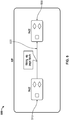
- FIG. 5 is a diagram illustrating a connection between pages 510 and 520 of an application 500.
- the pages 510 can communicate with one another using page inputs 530 when the application 500 navigates from one page to another.
- the page 510 can provide, as page inputs 530, parameters to the page 520.
- the parameters can be URL parameters, as described above.
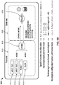
- FIGS. 6A and 6B illustrate a flow of actions between components of a frontend 610 and a backend 630 of a building block 600.
- the building block 600 can be a business component or a page.
- the frontend 610 can be a micro frontend.
- the frontend 610 includes a store 615 and user interface components 611 - 614.
- the user interface components include two input text elements 611 and 612, a result element 613, and a click button 614.
- Each of the user interface components 611 - 613 include attributes that are bound, e.g., using declarative binding, to the model for the frontend 610.
- the click button 614 includes an action that is bound, e.g., using declarative binding, to the reducer function 631 of the backend.
- the store 615 receives, from the button, action data specifying that the button 614 was selected. Based on the binding, the store 615 sends the action data to the reducer 631 to which the action is bound. The store 615 also sends the current model to the reducer function 631.
- the model includes the attributes of the user interface components 611 - 613.
- the reducer function 631 generates an updated model based on the received model and the action data. The updated model is automatically reflected on the user interface components 611 - 613 via the bindings between the attributes and the model. That is, the user interface components 611 - 613 will present the attributes of the updated model in response to the store 615 receiving the updated model from the reducer function 631 due to the bindings.
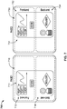
- FIG. 7 is a diagram illustrating a flow of actions between components of frontends and backends of building blocks 711 and 731.
- the building blocks 711 and 731 can be business components of pages 710 and 730, respectively.
- Each building block 711 and 731 has its own frontend and backend that communicate with each other. This enables developers to vertically slice an application and maximizes code reuse.
- the building blocks 711 and 731 are structured like micro-pages that can cooperate with each other, e.g., using messages. The page code is minimized and becomes optional as each building block can act as an independent unit.
- fronted monoliths that requires the duplication of page logic for managing groups of widgets and glue code with the rest of the page-specific business logic, which easily became messy and difficult for developers to manage, e.g., across multiple teams.
- the duplication of code in frontend monoliths also hinders non-code and low-code approaches.
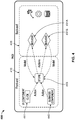
- FIG. 8 is a diagram illustrating an example user interface 800 generated using building blocks.
- the user interface 800 can be generated based on a summary display component and a map component being placed into the configuration user interface 120 of FIG. 1 and connected together.
- the user interfaces 800 includes a summary display element 810 that displays a summary of data for a geographic area displayed by a map display element 820.
- the summary display element 810 can be implemented as a business component that includes a user interface component for each piece of data shown in the summary.
- the business component can include a user interface component for open alarms, a user interface component for overall conditions, etc.
- Each user interface component can include an attribute that it presents and each attribute can be bound to the model for the summary display element 810. In this way, when the model is updated, the attributes displayed by the summary display element are also updated.
- the map display element 820 can also be implemented as a business component that includes a map as a user interface component.
- the micro frontend of the map display element 820 can be bound to the micro frontend of the summary display element.
- the micro frontend of the map display element 820 can send a message to the micro frontend of the summary display element 810.
- the message can include action data specifying that the geographic area has changed and data specifying the updated geographic area that is visible in the map display element 820.
- the store of the summary display element 810 can send a current model and the action data to a reducer function that generates an updated model based on the current model and the action data.
- the reducer function can provide the updated model to the store of the summary display element 810, which can update the user interface components, e.g., the open alarms component, to present its updated attributed of the updated model.
- FIG. 9 is a flow chart of an example process 900 for developing an application using building blocks that include micro frontends.
- the process 900 can be performed by the application development system 110.
- Operations of the process 900 can also be implemented as instructions stored on non-transitory computer readable media, and execution of the instructions by one or more data processing apparatus can cause the one or more data processing apparatus to perform the operations of the process 900.
- a configuration user interface is provided (910).
- the application development system 110 can provide a configuration user interface that enables a user, e.g., an application developer, to arrange building blocks in a layout within the configuration user interface.
- the configuration user interface can enable a user to drag and drop building blocks in the configuration user interface from a menu of configured building blocks.
- the application development system 110 can provide the configuration user interface to a client device of the user.
- the layout corresponds to how the user interface components of the micro frontends of the building blocks will be presented on a page generated based on the arrangement.
- the building blocks shown within the configuration user interface can show the user interface components of the building blocks the same as, or similar to, how the user interface components will be shown on the page.
- the configuration user interface also enables the user to define the communications between the building blocks, e.g., between the micro frontends of the building blocks.
- the configuration user interface enables the user to connect two building blocks that are to communicate with each other when presented on a page by an application, e.g., by a web browser or native application.
- a menu can be used to select, for each building block, which other building blocks the building block will receive messages, e.g., messages that define actions.
- the user can define the particular instance of the building block that will receive messages from another instance of another building block as there can be multiple instances of the same building block on a page.
- the configuration user interface can enable a user to specify the types of messages that a building block is to receive from another building block as some building blocks may output multiple different types of messages with different actions or other data.
- Data specifying a layout of building blocks is received (920). After arranging building blocks within the configuration user interface and defining the communications between the building blocks, the user can save the layout. In response, the client device can send data defining the layout to the application development system 110. This data can specify the building blocks in the layout, the arrangement (e.g., relative positions) of the building blocks within the layout, and the communications defined by the user.
- User interface data is generated based on the data specifying the layout of the building blocks (930).
- the application development system 110 can generate the user interface data based on the data specifying the layout of building blocks and an application that will present the user interface.
- the user interface data can include code that, when processed by an application such as a web browser or native application, causes the application to generate a user interface (e.g., page) that presents the user interface components of the micro frontends of the building blocks in the arrangement defined by the user.
- the application development system 110 can generate Hypertext Markup Language (HTML) code, cascaded style sheets (CSS), JavaScript, and/or other appropriate code that presents the user interface elements of the micro frontends.
- HTML Hypertext Markup Language
- CSS cascaded style sheets
- JavaScript JavaScript
- the application development system 110 can generate an HTML document that registers each of the micro frontends of the building blocks in the layout.
- the web browser will process the code of the micro frontends and present the user interface components of the micro frontends within the web page represented by the HTML document.
- the application development system 110 can also generate declarative bindings that define the communications between the micro frontends of the page.
- the user can then provide the user interface data for presentation in applications on other devices.
- the user can load an HTML document for a web page on a website for other users to download using a web browser.
- These web browsers can process the code in the HMTL document and present the web page represented by the HTML document.
- the micro frontends can communicate based on the declarative bindings and send messages to their respective backends in response to actions. For example, if a user interacts with the user interface component of a micro frontend presented by a web browser, the micro frontend can send obtain a current model for the micro frontend from its store and send the model and data specifying the action to its backend. The backend can use its reduced function to update the model and send the updated model to the micro frontend being presented by the web browser. In turn, the micro frontend can update its user interface component, e.g., to display different content, based on the updated model.
- Embodiments of the subject matter and the functional operations described in this specification can be implemented in digital electronic circuitry, in tangibly-embodied computer software or firmware, in computer hardware, including the structures disclosed in this specification and their structural equivalents, or in combinations of one or more of them.
- Embodiments of the subject matter described in this specification can be implemented as one or more computer programs, i.e., one or more modules of computer program instructions encoded on a tangible non transitory program carrier for execution by, or to control the operation of, data processing apparatus.
- the program instructions can be encoded on an artificially generated propagated signal, e.g., a machine-generated electrical, optical, or electromagnetic signal, that is generated to encode information for transmission to suitable receiver apparatus for execution by a data processing apparatus.
- the computer storage medium can be a machine-readable storage device, a machine-readable storage substrate, a random or serial access memory device, or a combination of one or more of them. The computer storage medium is not, however, a propagated signal.
- data processing apparatus refers to data processing hardware and encompasses all kinds of apparatus, devices, and machines for processing data, including by way of example a programmable processor, a computer, or multiple processors or computers.
- the apparatus can also be or further include special purpose logic circuitry, e.g., an FPGA (field programmable gate array) or an ASIC (application specific integrated circuit).
- the apparatus can optionally include, in addition to hardware, code that creates an execution environment for computer programs, e.g., code that constitutes processor firmware, a protocol stack, a database management system, an operating system, or a combination of one or more of them.
- a computer program which may also be referred to or described as a program, software, a software application, a module, a software module, a script, or code, can be written in any form of programming language, including compiled or interpreted languages, or declarative or procedural languages, and it can be deployed in any form, including as a stand alone program or as a module, component, subroutine, or other unit suitable for use in a computing environment.
- a computer program may, but need not, correspond to a file in a file system.
- a program can be stored in a portion of a file that holds other programs or data, e.g., one or more scripts stored in a markup language document, in a single file dedicated to the program in question, or in multiple coordinated files, e.g., files that store one or more modules, sub programs, or portions of code.
- a computer program can be deployed to be executed on one computer or on multiple computers that are located at one site or distributed across multiple sites and interconnected by a communication network.
- an “engine,” or “software engine,” refers to a software implemented input/output system that provides an output that is different from the input.
- An engine can be an encoded block of functionality, such as a library, a platform, a software development kit ("SDK”), or an object.
- SDK software development kit
- Each engine can be implemented on any appropriate type of computing device, e.g., servers, mobile phones, tablet computers, notebook computers, music players, e book readers, laptop or desktop computers, PDAs, smart phones, or other stationary or portable devices, that includes one or more processors and computer readable media. Additionally, two or more of the engines may be implemented on the same computing device, or on different computing devices.
- the processes and logic flows described in this specification can be performed by one or more programmable computers executing one or more computer programs to perform functions by operating on input data and generating output.
- the processes and logic flows can also be performed by, and apparatus can also be implemented as, special purpose logic circuitry, e.g., an FPGA (field programmable gate array) or an ASIC (application specific integrated circuit).
- special purpose logic circuitry e.g., an FPGA (field programmable gate array) or an ASIC (application specific integrated circuit).
- Computers suitable for the execution of a computer program include, by way of example, general or special purpose microprocessors or both, or any other kind of central processing unit.
- a central processing unit will receive instructions and data from a read only memory or a random access memory or both.
- the essential elements of a computer are a central processing unit for performing or executing instructions and one or more memory devices for storing instructions and data.
- a computer will also include, or be operatively coupled to receive data from or transfer data to, or both, one or more mass storage devices for storing data, e.g., magnetic, magneto optical disks, or optical disks.
- mass storage devices for storing data, e.g., magnetic, magneto optical disks, or optical disks.
- a computer need not have such devices.
- a computer can be embedded in another device, e.g., a mobile telephone, a personal digital assistant (PDA), a mobile audio or video player, a game console, a Global Positioning System (GPS) receiver, or a portable storage device, e.g., a universal serial bus (USB) flash drive, to name just a few.
- PDA personal digital assistant
- GPS Global Positioning System
- USB universal serial bus
- Computer readable media suitable for storing computer program instructions and data include all forms of non volatile memory, media and memory devices, including by way of example semiconductor memory devices, e.g., EPROM, EEPROM, and flash memory devices; magnetic disks, e.g., internal hard disks or removable disks; magneto optical disks; and CD ROM and DVD-ROM disks.
- semiconductor memory devices e.g., EPROM, EEPROM, and flash memory devices
- magnetic disks e.g., internal hard disks or removable disks
- magneto optical disks e.g., CD ROM and DVD-ROM disks.
- the processor and the memory can be supplemented by, or incorporated in, special purpose logic circuitry.
- a computer having a display device, e.g., a CRT (cathode ray tube) or LCD (liquid crystal display) monitor, for displaying information to the user and a keyboard and a pointing device, e.g., a mouse or a trackball, by which the user can provide input to the computer.
- a display device e.g., a CRT (cathode ray tube) or LCD (liquid crystal display) monitor
- a keyboard and a pointing device e.g., a mouse or a trackball
- Other kinds of devices can be used to provide for interaction with a user as well; for example, feedback provided to the user can be any form of sensory feedback, e.g., visual feedback, auditory feedback, or tactile feedback; and input from the user can be received in any form, including acoustic, speech, or tactile input.
- a computer can interact with a user by sending documents to and receiving documents from a device that is used by the user; for example, by sending web pages to
- Embodiments of the subject matter described in this specification can be implemented in a computing system that includes a back end component, e.g., as a data server, or that includes a middleware component, e.g., an application server, or that includes a front end component, e.g., a client computer having a graphical user interface or a Web browser through which a user can interact with an implementation of the subject matter described in this specification, or any combination of one or more such back end, middleware, or front end components.
- the components of the system can be interconnected by any form or medium of digital data communication, e.g., a communication network. Examples of communication networks include a local area network (LAN) and a wide area network (WAN), e.g., the Internet.
- LAN local area network
- WAN wide area network
- the computing system can include clients and servers.
- a client and server are generally remote from each other and typically interact through a communication network. The relationship of client and server arises by virtue of computer programs running on the respective computers and having a client-server relationship to each other.
- a server transmits data, e.g., an HTML page, to a user device, e.g., for purposes of displaying data to and receiving user input from a user interacting with the user device, which acts as a client.
- Data generated at the user device e.g., a result of the user interaction, can be received from the user device at the server.
- FIG. 10 shows a schematic diagram of a generic computer system 1000.
- the system 1000 can be used for the operations described in association with any of the computer-implemented methods described previously, according to one implementation.
- the system 1000 includes a processor 1010, a memory 1020, a storage device 1030, and an input/output device 1040.
- Each of the components 1010, 1020, 1030, and 1040 are interconnected using a system bus 1050.
- the processor 1010 is capable of processing instructions for execution within the system 1000.
- the processor 1010 is a single-threaded processor.
- the processor 1010 is a multi-threaded processor.
- the processor 1010 is capable of processing instructions stored in the memory 1020 or on the storage device 1030 to display graphical information for a user interface on the input/output device 1040.
- the memory 1020 stores information within the system 1000.
- the memory 1020 is a computer-readable medium.
- the memory 1020 is a volatile memory unit.
- the memory 1020 is a non-volatile memory unit.
- the storage device 1030 is capable of providing mass storage for the system 1000.
- the storage device 1030 is a computer-readable medium.
- the storage device 1030 may be a floppy disk device, a hard disk device, an optical disk device, or a tape device.
- the input/output device 1040 provides input/output operations for the system 1000.
- the input/output device 1040 includes a keyboard and/or pointing device.
- the input/output device 1040 includes a display unit for displaying graphical user interfaces.
Landscapes
- Engineering & Computer Science (AREA)
- Theoretical Computer Science (AREA)
- General Engineering & Computer Science (AREA)
- Physics & Mathematics (AREA)
- Software Systems (AREA)
- General Physics & Mathematics (AREA)
- Human Computer Interaction (AREA)
- Geometry (AREA)
- Evolutionary Computation (AREA)
- Computer Hardware Design (AREA)
- User Interface Of Digital Computer (AREA)
- Architecture (AREA)
- Computational Mathematics (AREA)
- Mathematical Analysis (AREA)
- Mathematical Optimization (AREA)
- Pure & Applied Mathematics (AREA)
Abstract
Description
- This application claims the benefit under 35 U.S.C. § 119(e) of
U.S. Patent Application No. 62/951,214 - This specification relates to a computing architecture that enables users to develop applications using building blocks that include micro frontends.
- Software developers often attempt to develop software components that can be reused to build new software. This can save time and reduce errors and testing time for the new software applications. One example of such reuse is a microservice architecture that structures applications as a group of services that can each be reused in other applications. Another example of reuse is a micro frontend architecture that structures user interfaces as a group of frontend components that can be reused in other user interfaces of other applications.
- This specification generally describes a computing architecture that enables users to develop applications using building block user interface elements ("building blocks") that include micro frontends that have a model-based state. A micro frontend can be in the form of one or more frontend components that can be included in a page, e.g., a web page or application page. Each micro frontend can have its own independent backend, e.g., in the form of a microservice, that is part of a building block, e.g., a business component, that includes the micro frontend. In this way, independent teams can develop building blocks that can be inserted into multiple user interfaces, e.g., multiple pages.
- The backend for a micro frontend can be connected to the user interface components of the micro fronted using declarative bindings, e.g., using JavaScript Object Notation (JSON). The use of declarative bindings enables the user interface components to be decoupled from the physical backend implementation and enables decoupling from specific user interface technologies. In this way, the user interface can optimize the rendering on specific user interface technologies. The micro frontends of a user interface can also be connected using declarative bindings that enable the micro frontends to communicate, e.g., using messages that include actions.
- A micro frontend can include a globally-managed model-based state that is changed based on actions received from the user interface or another micro frontend. For example, a micro frontend can include a global store, which can be implemented on the frontend, that manages the state for the micro frontend. The state can represent the micro frontend's model. When the micro frontend receives an action, e.g., based on user interaction with the user interface component or an action received from another micro frontend, the store can send the action to the backend. The backend can include one or more reducers that generates an updated model, e.g., without changing the model, based on the action and the previous model and sends the updated model to the store. Thus, rather than being mutated, an immutable model is threaded through the reducer function(s), which yields the new, immutable version of the model for the store. This model-based approach fits well as a distributed and concurrent computation paradigm at a larger scale where actors achieve a distrusted computation by exchanging messages and encapsulating their state. This also enables business components, which can be a combination of one or more micro frontends with a corresponding backend, to be location transparent, which means that a single page in an application can be composed by business components running on distinct servers. Inside of each actor, e.g., each business component, the state management enables stateless computation to be predictable, parallelized, and horizontally scalable.
- In general, one innovative aspect of the subject matter described in this specification can be embodied in methods that include providing a configuration user interface that enables a user to select and arrange building block user interface elements in a layout for a page; receiving, from the configuration user interface, data specifying a layout of one or more building block user interface elements that each include a micro frontend and corresponding backend logic, wherein: each micro frontend includes one or more user interface components and a store that manages a model that represents a state of the one or more user interface components of the micro frontend; and the corresponding backend for each micro frontend includes a function that updates the model of the micro frontend based on a previous model of the micro frontend and an action; and generating user interface data that, when processed by an application, causes the application to generate a user interface that presents the one or more user interface components of each of the one or more building block user interface elements in the layout specified by the received data. Other implementations of this aspect include corresponding systems, apparatus, and computer programs, configured to perform the actions of the methods, encoded on computer storage devices.
- These and other implementations can each optionally include one or more of the following features. Some aspects can include receiving data specifying that a first building block user interface element is a subscriber to messages generated by a second building block user interface element and generating a declarative binding between the first building block user interface element and the second building block user interface element.
- In some aspects, the backend of each building block user interface element includes one or more reducer functions. A given user interface component of each building block user interface element can include an action that is bound to a corresponding reducer function of the backend of the building block user interface element. The store of each micro frontend can be configured to send a current model maintained by the store and action data specifying a detected action to the corresponding reducer function in response to detecting the action. Each reducer function can be configured to generate an updated model based on the received current model and action data and provide the updated model to the store.
- In some aspects, each of the one or more user interface components is bound to a respective attribute of the model. Some aspects can include updating the one or more user interface components in response to receiving an updated model that includes updated attributes. Some aspects can include receiving data defining custom business logic for the user interface.
- The subject matter described in this specification can be implemented in particular embodiments and may result in one or more of the following advantages. Using the actor-like paradigm for communication between business components that is based on asynchronous message passing not only enables local transparency - e.g., different business components on a single page can run on physically different back-ends - but also enables temporal decoupling such that a receiving business component does not need to be in any way active and listening for messages. Instead, the business component is activated by the architecture on demand. In addition, the sending business component does not need to wait for the message to be processed, both of which enables better resource utilization and more efficient communication.
- The interplay between model-based state, declarative configuration and composition, and vertical reuse and encapsulation provided by business components and other building blocks described in this document allows component and toolkit developers to safely define business logic within well-defined physical and logical perimeters, enables app developers to leverage a substantial amount of pre-built, tested, and vertical building blocks that speak their same business language, and lets designers draw from the thinking and user experience that inspired and were infused in the whole platform, from the most basic user interface components to declarative layouts and page navigation. The architecture can be used to enable developers to quickly create reusable applications with no-code and/or low-code approaches and to build and allow the building of reusable vertical toolkits that contain a set of building blocks, e.g., a set of building blocks for a particular team of developers that are typical for that team's business context. Using such building blocks reduces errors introduced by regenerating similar micro frontends for each application, rather than using pre-tested building blocks.
-
-
FIG. 1 is a block diagram of an example environment in which an application development system enables a user to develop an application using building blocks that include micro frontends. -
FIG. 2 is a diagram illustrating components of an example page of an application. -
FIG. 3 is a diagram illustrating components of an example business component. -
FIG. 4 is a diagram illustrating components of another example page of an application. -
FIG. 5 is a diagram illustrating a connection between pages of an application. -
FIGS. 6A and6B illustrate a flow of actions between components of a frontend and a backend of a building block. -
FIG. 7 is a diagram illustrating a flow of actions between components of frontends and backends of building blocks. -
FIG. 8 is a diagram illustrating an example user interface generated using building blocks. -
FIG. 9 is a flow chart of an example process for developing an application using building blocks that include micro frontends. -
FIG. 10 is a schematic diagram of a computer system. - Like reference numbers and designations in the various drawings indicate like elements.
-
FIG. 1 is a block diagram of anexample environment 100 in which anapplication development system 110 enables a user to develop an application using building block user interface elements ("building blocks") that include micro frontends. Theapplication development system 110 includes afrontend configuration engine 113, abackend configuration engine 115, and a building blocksdata storage device 117 that store building blocks. - The
frontend configuration engine 113 enables users, e.g., application developers, to generate a frontend of an application, e.g., one or more pages or other user interfaces of the application using aconfiguration user interface 120. For example, thefrontend configuration engine 113 can enable a user to generate web pages, application pages of native applications developed for particular platforms or devices, or other computer-generated user interfaces. For ease of subsequent description, theapplication development system 110 will be described largely in terms of "pages," which can refer to any of these types of user interfaces. - A user can create a page by adding building blocks to an
editor page 127 of theuser configuration interface 120. In this example, theconfiguration user interface 120 includes amenu 126 of configured building blocks that the user can select and place in theeditor page 127 of theconfiguration user interface 120. For example, a user can drag and drop a building block from themenu 126 to theeditor page 127. The user can arrange the building blocks within theeditor page 127 to configure the layout for the user interface. For example, the location of a building block within the user interface can represent the actual location of a user interface component generated and presented within the page when the configured page is presented on a user device, e.g., when a configured web page is presented in a web browser running on a user device. - Each building block can include a micro frontend and a corresponding independent backend component. A micro frontend can be in the form of one or more frontend components that are presented within a page that includes the micro front end. For example, a micro frontend can include one or more images (or image presentation components in which an image is selected and presented), buttons, icons, slider controls, selector lists, dropdown menus, etc.
- The backend of a building block can be in the form of a microservice or other business logic. In some implementations, the backend of a building block includes one or more functions, e.g., one or more reducer functions, that update a model of the frontend based on data specifying an action received from the micro frontend. Importantly, the building blocks can have different types of backends, e.g., with logic or code that runs on different platforms. For example, the backend of a building block for a button may be a microservice programmed using a first programming language that runs on a first server and the backend of a building block for presenting images may be a microservice programmed using a second programming language different from the first programming language and that runs on a second server different from the first server. In this way, independent teams can develop building blocks that can be inserted into multiple user interfaces, e.g., multiple pages.
- The backend for a micro frontend can be connected to the user interface components of the micro fronted using declarative bindings, e.g., using JSON. The micro frontends of a user interface can also be connected to each other using declarative bindings that enable the micro frontends to communicate, e.g., using messages that include actions, as described in more detail below.
- A micro frontend of a building block can include a globally-managed model-based state that is changed based on actions. The action can be in the form of a user interaction with the frontend component(s) of the micro frontend, a message from another micro frontend, or a message from the page that includes the micro frontend. Each micro frontend can include a global store, which can be implemented on the frontend (e.g., as code of a web page or native application), that maintains and manages the state for the micro frontend. The state can represent the micro frontend's model. When the micro frontend receives an action, the store can send data specifying the action to the backend corresponding to the micro frontend. The backend can include one or more functions, e.g., reducer functions, that receives the model and the data specifying the action and generates an updated model based on the action and the received model. The reducer function(s) can generate the updated model without changing the model itself.
- The model describes the state of the user interface components of the micro frontend. The model defines how the user interface elements are displayed and how actions (e.g., user interactions with the user interface elements, another micro frontend, or another user interface component) impact the business logic and thereby updates the user interface components of the micro frontend. For example, in a page where devices are selected among a list of possible devices, a user interface component of the micro frontend would need to represent the list (e.g., in the form of a drop down menu) and enable the user viewing the page to select one or more of the devices from the list.
- One example way of implementing this would be a model that includes a list of devices (e.g., their stock-keeping units (SKUs)) represented as strings and a list among this list which have been selected by the user which may also be represented as strings. The relationship between the list of devices displayed by the user interface component and the business logic of the backend can be established using declarative bindings on the page configuration. For example, if JSON is used, this relationship can be specified as "choices: ${possibleDevices}". The correlation between the user selecting the devices and the corresponding population of these values can be implemented by the inner workings on the client, driven by the bindings configuration for the page. For example, if JSON is used, the correlation can be defined by "selected: ${selectedDevices}", where "selectedDevices" is the name of the model field in the model of the building block. If JSON is used, the model at any given time may be in the form of:
 {
 "possibleDevices": ["Dev42", "Dev43"],
 "selectedDevices": ["Dev42"]
 }
 "subscriptions": {
 } "onDeviceSelect": "${countDevices}"
 "deviceIndicator1": {
 "type": "Devicelndicator",
 } "subscribedTo": { "onDeviceSelect": "deviceList1" }
Claims (14)
- A method performed by one or more data processing apparatus, the method comprising:providing a configuration user interface that enables a user to select and arrange building block user interface elements in a layout for a page;receiving, from the configuration user interface, data specifying a layout of one or more building block user interface elements that each include a micro frontend and corresponding backend logic, wherein:each micro frontend includes one or more user interface components and a store that manages a model that represents a state of the one or more user interface components of the micro frontend; andthe corresponding backend for each micro frontend includes a function that updates the model of the micro frontend based on a previous model of the micro frontend and an action; andgenerating user interface data that, when processed by an application, causes the application to generate a user interface that presents the one or more user interface components of each of the one or more building block user interface elements in the layout specified by the received data.
- The method of claim 1, further comprising:receiving data specifying that a first building block user interface element is a subscriber to messages generated by a second building block user interface element; andgenerating a declarative binding between the first building block user interface element and the second building block user interface element.
- The method of any preceding claim, wherein the backend of each building block user interface element comprises one or more reducer functions.
- The method of any preceding claim, wherein a given user interface component of each building block user interface element comprises an action that is bound to a corresponding reducer function of the backend of the building block user interface element.
- The method of claim 4, wherein the store of each micro frontend is configured to send a current model maintained by the store and action data specifying a detected action to the corresponding reducer function in response to detecting the action.
- The method of claim 4 or 5, wherein each reducer function is configured to generate an updated model based on the received current model and action data and provide the updated model to the store.
- The method of any preceding claim, wherein each of the one or more user interface components is bound to a respective attribute of the model.
- The method of any preceding claim, further comprising updating the one or more user interface components in response to receiving an updated model that includes updated attributes.
- The method of any preceding claim, further comprising receiving data defining custom business logic for the user interface.
- A system, comprising:one or more computers; andone or more computer memory devices interoperably coupled with the one or more computers and having tangible, non-transitory, machine-readable media storing one or more instructions that, when executed by the one or more computers, perform operations comprising:providing a configuration user interface that enables a user to select and arrange building block user interface elements in a layout for a page;receiving, from the configuration user interface, data specifying a layout of one or more building block user interface elements that each include a micro frontend and corresponding backend logic, wherein:each micro frontend includes one or more user interface components and a store that manages a model that represents a state of the one or more user interface components of the micro frontend; andthe corresponding backend for each micro frontend includes a function that updates the model of the micro frontend based on a previous model of the micro frontend and an action; andgenerating user interface data that, when processed by an application, causes the application to generate a user interface that presents the one or more user interface components of each of the one or more building block user interface elements in the layout specified by the received data.
- The system of claim 10, wherein the instructions, when executed by the one or more computers, cause the one or more computers to perform the method of one or more of claims 2 to 9.
- A non-transitory, computer-readable medium storing one or more instructions executable by a computer system to perform operations comprising:providing a configuration user interface that enables a user to select and arrange building block user interface elements in a layout for a page;receiving, from the configuration user interface, data specifying a layout of one or more building block user interface elements that each include a micro frontend and corresponding backend logic, wherein:each micro frontend includes one or more user interface components and a store that manages a model that represents a state of the one or more user interface components of the micro frontend; andthe corresponding backend for each micro frontend includes a function that updates the model of the micro frontend based on a previous model of the micro frontend and an action; andgenerating user interface data that, when processed by an application, causes the application to generate a user interface that presents the one or more user interface components of each of the one or more building block user interface elements in the layout specified by the received data.
- The non-transitory, computer-readable medium of claim 12, wherein the operations comprise:receiving data specifying that a first building block user interface element is a subscriber to messages generated by a second building block user interface element; andgenerating a declarative binding between the first building block user interface element and the second building block user interface element.
- The non-transitory, computer-readable medium of claim 12 or 13, wherein the backend of each building block user interface element comprises one or more reducer functions.
Applications Claiming Priority (2)
| Application Number | Priority Date | Filing Date | Title |
|---|---|---|---|
| US201962951214P | 2019-12-20 | 2019-12-20 | |
| US16/902,931 US11216602B2 (en) | 2019-12-20 | 2020-06-16 | Micro frontends with model-based state |
Publications (2)
| Publication Number | Publication Date |
|---|---|
| EP3839722A1 true EP3839722A1 (en) | 2021-06-23 |
| EP3839722B1 EP3839722B1 (en) | 2024-07-31 |
Family
ID=73855639
Family Applications (1)
| Application Number | Title | Priority Date | Filing Date |
|---|---|---|---|
| EP20215235.1A Active EP3839722B1 (en) | 2019-12-20 | 2020-12-17 | Micro frontends with model-based state |
Country Status (3)
| Country | Link |
|---|---|
| US (1) | US11216602B2 (en) |
| EP (1) | EP3839722B1 (en) |
| ES (1) | ES2991807T3 (en) |
Cited By (3)
| Publication number | Priority date | Publication date | Assignee | Title |
|---|---|---|---|---|
| US20230037019A1 (en) * | 2021-07-29 | 2023-02-02 | Oracle International Corporation | Techniques for distributed interface component generation |
| US20240296026A1 (en) * | 2023-03-03 | 2024-09-05 | Engineer.ai Corp. | Systems and methods of building blocks in a device application |
| US20240330021A1 (en) * | 2023-04-03 | 2024-10-03 | Capital One Services, Llc | Contextual user interface component |
Families Citing this family (25)
| Publication number | Priority date | Publication date | Assignee | Title |
|---|---|---|---|---|
| CN114647518B (en) * | 2020-12-21 | 2025-11-07 | 腾讯科技(深圳)有限公司 | Micro front-end system, sub-application loading method and computer readable storage medium |
| WO2022203381A1 (en) * | 2021-03-23 | 2022-09-29 | (주)인스웨이브시스템즈 | Integrated user interface platform development system and method of single-page application type |
| US20240176599A1 (en) * | 2021-03-23 | 2024-05-30 | Inswave Systems Co., Ltd. | User interface platform integrated-development system and method having microservice architecture |
| CN113495723B (en) * | 2021-07-28 | 2023-09-22 | 北京信安世纪科技股份有限公司 | Method, device and storage medium for calling functional component |
| CN113641360B (en) * | 2021-08-31 | 2023-08-22 | 平安银行股份有限公司 | Configuration method, device, equipment and storage medium of system front end |
| US20230103361A1 (en) * | 2021-10-06 | 2023-04-06 | Saudi Arabian Oil Company | Supply Chain Alert Management |
| CN116360755A (en) * | 2021-12-28 | 2023-06-30 | 美的集团股份有限公司 | Method for generating device control application, electronic device and computer storage medium |
| US12493898B2 (en) * | 2021-12-30 | 2025-12-09 | Yahoo Ad Tech Llc | System and method for thin explore/exploit layer for providing additional degree of freedom in recommendations |
| US11748068B2 (en) * | 2022-02-08 | 2023-09-05 | Oracle Financial Services Software Limited | Building base applications with user interface micro frontends |
| CN114816348A (en) * | 2022-04-18 | 2022-07-29 | 北京高灵智腾信息科技有限公司 | Programmable new HIS development system |
| CA3261303A1 (en) | 2022-07-13 | 2024-01-18 | Grass Valley Canada | System and method for generating customized user interface with multi-application functionality |
| CN115390802B (en) * | 2022-08-23 | 2025-01-21 | 上海百秋新网商数字科技有限公司 | Application component development method, system, device and storage medium |
| CN116204175A (en) * | 2023-02-27 | 2023-06-02 | 深圳市科南软件有限公司 | Front-end code-free development framework, method, medium and equipment driven by UI model |
| US12321722B2 (en) | 2023-03-12 | 2025-06-03 | Engineer.ai Corp. | Systems and methods for a device application with certified building block components |
| US12182538B2 (en) | 2023-03-12 | 2024-12-31 | Engineer.ai Corp. | Systems and methods for certifying features for generating a device application |
| US20240303047A1 (en) * | 2023-03-12 | 2024-09-12 | Engineer.ai Corp. | Systems and methods for building block component certification |
| US12381933B2 (en) * | 2023-05-31 | 2025-08-05 | Capital One Services, Llc | Systems and methods for monitoring application activity in micro frontend dependent applications without use of a shell application |
| CN116610319B (en) * | 2023-06-06 | 2024-05-14 | 易智瑞信息技术有限公司 | A method and system for building map applications based on a low-code platform |
| US12321761B2 (en) * | 2023-06-12 | 2025-06-03 | Wells Fargo Bank, N.A. | Hub for micro front-end services |
| EP4488824A1 (en) * | 2023-07-06 | 2025-01-08 | Abb Schweiz Ag | A human-machine interface |
| CN117056625B (en) * | 2023-07-19 | 2026-02-24 | 超聚变数字技术股份有限公司 | Display methods and related equipment |
| US20250077315A1 (en) * | 2023-08-28 | 2025-03-06 | Capital One Services, Llc | User segmentation for dynamic personalized application flows |
| US20250077229A1 (en) * | 2023-08-28 | 2025-03-06 | Capital One Services, Llc | Modular application system decomposed into separate micro frontends to support personalized application flows |
| CN117273630A (en) * | 2023-10-07 | 2023-12-22 | 国电南瑞科技股份有限公司 | A substation digital system application ecological construction method and system |
| US12578977B2 (en) | 2023-11-27 | 2026-03-17 | Wells Fargo Bank, N.A. | Omni-channel micro frontend control plane |
Citations (2)
| Publication number | Priority date | Publication date | Assignee | Title |
|---|---|---|---|---|
| US20070266329A1 (en) * | 2005-04-19 | 2007-11-15 | The Mathworks, Inc. | Graphical state machine based programming for a graphical user interface |
| US20180081639A1 (en) * | 2016-09-16 | 2018-03-22 | Oracle International Corporation | Systems and methods for building applications using building blocks linkable with metadata |
Family Cites Families (9)
| Publication number | Priority date | Publication date | Assignee | Title |
|---|---|---|---|---|
| US5845299A (en) * | 1996-07-29 | 1998-12-01 | Rae Technology Llc | Draw-based editor for web pages |
| US20070265929A1 (en) * | 2006-04-26 | 2007-11-15 | Michael Danninger | Portal page personalization offering a direct manipulative window arrangement functionality |
| US8780130B2 (en) * | 2010-11-30 | 2014-07-15 | Sitting Man, Llc | Methods, systems, and computer program products for binding attributes between visual components |
| US20140258841A1 (en) * | 2013-03-07 | 2014-09-11 | Smugmug, Inc. | Method of building a customizable website |
| EP3153966A1 (en) * | 2015-10-09 | 2017-04-12 | Hewlett-Packard Enterprise Development LP | Graphical user interface editors |
| US10509394B2 (en) * | 2015-11-16 | 2019-12-17 | Rockwell Automation Technologies, Inc. | User interface widget modeling and placement |
| US10613725B2 (en) * | 2017-10-13 | 2020-04-07 | Adobe Inc. | Fixing spaced relationships between graphic objects |
| US10599752B2 (en) * | 2018-02-26 | 2020-03-24 | Servicenow, Inc. | Web page acquisition and rendering with inter-component data binding |
| US10678600B1 (en) * | 2019-03-01 | 2020-06-09 | Capital One Services, Llc | Systems and methods for developing a web application using micro frontends |
-
2020
- 2020-06-16 US US16/902,931 patent/US11216602B2/en active Active
- 2020-12-17 EP EP20215235.1A patent/EP3839722B1/en active Active
- 2020-12-17 ES ES20215235T patent/ES2991807T3/en active Active
Patent Citations (2)
| Publication number | Priority date | Publication date | Assignee | Title |
|---|---|---|---|---|
| US20070266329A1 (en) * | 2005-04-19 | 2007-11-15 | The Mathworks, Inc. | Graphical state machine based programming for a graphical user interface |
| US20180081639A1 (en) * | 2016-09-16 | 2018-03-22 | Oracle International Corporation | Systems and methods for building applications using building blocks linkable with metadata |
Cited By (5)
| Publication number | Priority date | Publication date | Assignee | Title |
|---|---|---|---|---|
| US20230037019A1 (en) * | 2021-07-29 | 2023-02-02 | Oracle International Corporation | Techniques for distributed interface component generation |
| US11949761B2 (en) * | 2021-07-29 | 2024-04-02 | Oracle International Corporation | Techniques for distributed interface component generation |
| US12348599B2 (en) | 2021-07-29 | 2025-07-01 | Oracle International Corporation | Techniques for distributed interface component generation |
| US20240296026A1 (en) * | 2023-03-03 | 2024-09-05 | Engineer.ai Corp. | Systems and methods of building blocks in a device application |
| US20240330021A1 (en) * | 2023-04-03 | 2024-10-03 | Capital One Services, Llc | Contextual user interface component |
Also Published As
| Publication number | Publication date |
|---|---|
| ES2991807T3 (en) | 2024-12-04 |
| US11216602B2 (en) | 2022-01-04 |
| EP3839722B1 (en) | 2024-07-31 |
| US20210192106A1 (en) | 2021-06-24 |
Similar Documents
| Publication | Publication Date | Title |
|---|---|---|
| EP3839722B1 (en) | Micro frontends with model-based state | |
| US10705942B1 (en) | Simulated testing of API | |
| US11822870B2 (en) | Customizable user interface layouts | |
| US10091628B2 (en) | Message based application state and card sharing methods for user devices | |
| US8789068B2 (en) | Method and system for changing execution environments during application execution | |
| US11321422B1 (en) | User-configurable aggregate web components | |
| US9430207B1 (en) | Automated cross-platform native mobile application generation with cloud driven user interface and workflow synthesis | |
| AU2013293535B2 (en) | Providing access to a remote application via a web client | |
| US8527939B2 (en) | GUI modeling of knowledge base in a modeling environment | |
| US11625243B2 (en) | Micro-application creation and execution | |
| US20170329614A1 (en) | Notifications in multi application user interfaces | |
| WO2023040443A1 (en) | Method and device for drawing canvas | |
| CN111045653B (en) | System generation method and device, computer readable medium and electronic equipment | |
| EP4575828A1 (en) | Method and apparatus for creating digital assistant, and device and storage medium | |
| WO2024249205A1 (en) | System and method for building server-driven user interface (sdui) mobile applications using no-code/low-code application builder | |
| US20150143267A1 (en) | SYSTEM AND METHOD FOR DEVELOPING A RULE-BASED EVENT-DRIVEN MULTI-LAYERED FRONTEND FOR BUSINESS SERVICES AND RENDERING THE GUIs ON MULTIPLE CLIENT DEVICES | |
| US11520473B2 (en) | Switch control for animations | |
| CN114265657A (en) | Method and device for displaying page of applet | |
| US10268490B2 (en) | Embedding user interface snippets from a producing application into a consuming application | |
| EP2909764A2 (en) | Portal for submitting business metadata for services | |
| Liu et al. | MUIT: a domain-specific language and its middleware for adaptive mobile web-based user interfaces in WS-BPEL | |
| CN113326079A (en) | Service version switching method, switching device, electronic equipment and storage medium | |
| US10768911B2 (en) | Managing software components for software application development | |
| CN118484180A (en) | System development method, device, equipment and storage medium | |
| Liu et al. | MUIT: a middleware for adaptive mobile web-based user interfaces in WS-BPEL |
Legal Events
| Date | Code | Title | Description |
|---|---|---|---|
| PUAI | Public reference made under article 153(3) epc to a published international application that has entered the european phase |
Free format text: ORIGINAL CODE: 0009012 |
|
| STAA | Information on the status of an ep patent application or granted ep patent |
Free format text: STATUS: THE APPLICATION HAS BEEN PUBLISHED |
|
| AK | Designated contracting states |
Kind code of ref document: A1 Designated state(s): AL AT BE BG CH CY CZ DE DK EE ES FI FR GB GR HR HU IE IS IT LI LT LU LV MC MK MT NL NO PL PT RO RS SE SI SK SM TR |
|
| STAA | Information on the status of an ep patent application or granted ep patent |
Free format text: STATUS: REQUEST FOR EXAMINATION WAS MADE |
|
| 17P | Request for examination filed |
Effective date: 20211216 |
|
| RBV | Designated contracting states (corrected) |
Designated state(s): AL AT BE BG CH CY CZ DE DK EE ES FI FR GB GR HR HU IE IS IT LI LT LU LV MC MK MT NL NO PL PT RO RS SE SI SK SM TR |
|
| STAA | Information on the status of an ep patent application or granted ep patent |
Free format text: STATUS: EXAMINATION IS IN PROGRESS |
|
| 17Q | First examination report despatched |
Effective date: 20230104 |
|
| GRAP | Despatch of communication of intention to grant a patent |
Free format text: ORIGINAL CODE: EPIDOSNIGR1 |
|
| STAA | Information on the status of an ep patent application or granted ep patent |
Free format text: STATUS: GRANT OF PATENT IS INTENDED |
|
| INTG | Intention to grant announced |
Effective date: 20240220 |
|
| GRAS | Grant fee paid |
Free format text: ORIGINAL CODE: EPIDOSNIGR3 |
|
| GRAA | (expected) grant |
Free format text: ORIGINAL CODE: 0009210 |
|
| STAA | Information on the status of an ep patent application or granted ep patent |
Free format text: STATUS: THE PATENT HAS BEEN GRANTED |
|
| AK | Designated contracting states |
Kind code of ref document: B1 Designated state(s): AL AT BE BG CH CY CZ DE DK EE ES FI FR GB GR HR HU IE IS IT LI LT LU LV MC MK MT NL NO PL PT RO RS SE SI SK SM TR |
|
| P01 | Opt-out of the competence of the unified patent court (upc) registered |
Free format text: CASE NUMBER: APP_37101/2024 Effective date: 20240620 |
|
| REG | Reference to a national code |
Ref country code: CH Ref legal event code: EP Ref country code: GB Ref legal event code: FG4D |
|
| REG | Reference to a national code |
Ref country code: DE Ref legal event code: R096 Ref document number: 602020034797 Country of ref document: DE |
|
| REG | Reference to a national code |
Ref country code: IE Ref legal event code: FG4D |
|
| REG | Reference to a national code |
Ref country code: LT Ref legal event code: MG9D |
|
| REG | Reference to a national code |
Ref country code: NL Ref legal event code: MP Effective date: 20240731 Ref country code: ES Ref legal event code: FG2A Ref document number: 2991807 Country of ref document: ES Kind code of ref document: T3 Effective date: 20241204 |
|
| PG25 | Lapsed in a contracting state [announced via postgrant information from national office to epo] |
Ref country code: PT Free format text: LAPSE BECAUSE OF FAILURE TO SUBMIT A TRANSLATION OF THE DESCRIPTION OR TO PAY THE FEE WITHIN THE PRESCRIBED TIME-LIMIT Effective date: 20241202 |
|
| REG | Reference to a national code |
Ref country code: AT Ref legal event code: MK05 Ref document number: 1709105 Country of ref document: AT Kind code of ref document: T Effective date: 20240731 |
|
| PG25 | Lapsed in a contracting state [announced via postgrant information from national office to epo] |
Ref country code: PT Free format text: LAPSE BECAUSE OF FAILURE TO SUBMIT A TRANSLATION OF THE DESCRIPTION OR TO PAY THE FEE WITHIN THE PRESCRIBED TIME-LIMIT Effective date: 20241202 |
|
| PGFP | Annual fee paid to national office [announced via postgrant information from national office to epo] |
Ref country code: DE Payment date: 20241023 Year of fee payment: 5 |
|
| PG25 | Lapsed in a contracting state [announced via postgrant information from national office to epo] |
Ref country code: NO Free format text: LAPSE BECAUSE OF FAILURE TO SUBMIT A TRANSLATION OF THE DESCRIPTION OR TO PAY THE FEE WITHIN THE PRESCRIBED TIME-LIMIT Effective date: 20241031 |
|
| PG25 | Lapsed in a contracting state [announced via postgrant information from national office to epo] |
Ref country code: NL Free format text: LAPSE BECAUSE OF FAILURE TO SUBMIT A TRANSLATION OF THE DESCRIPTION OR TO PAY THE FEE WITHIN THE PRESCRIBED TIME-LIMIT Effective date: 20240731 Ref country code: GR Free format text: LAPSE BECAUSE OF FAILURE TO SUBMIT A TRANSLATION OF THE DESCRIPTION OR TO PAY THE FEE WITHIN THE PRESCRIBED TIME-LIMIT Effective date: 20241101 Ref country code: PL Free format text: LAPSE BECAUSE OF FAILURE TO SUBMIT A TRANSLATION OF THE DESCRIPTION OR TO PAY THE FEE WITHIN THE PRESCRIBED TIME-LIMIT Effective date: 20240731 Ref country code: FI Free format text: LAPSE BECAUSE OF FAILURE TO SUBMIT A TRANSLATION OF THE DESCRIPTION OR TO PAY THE FEE WITHIN THE PRESCRIBED TIME-LIMIT Effective date: 20240731 |
|
| PGFP | Annual fee paid to national office [announced via postgrant information from national office to epo] |
Ref country code: GB Payment date: 20241001 Year of fee payment: 5 |
|
| PG25 | Lapsed in a contracting state [announced via postgrant information from national office to epo] |
Ref country code: BG Free format text: LAPSE BECAUSE OF FAILURE TO SUBMIT A TRANSLATION OF THE DESCRIPTION OR TO PAY THE FEE WITHIN THE PRESCRIBED TIME-LIMIT Effective date: 20240731 |
|
| PG25 | Lapsed in a contracting state [announced via postgrant information from national office to epo] |
Ref country code: LV Free format text: LAPSE BECAUSE OF FAILURE TO SUBMIT A TRANSLATION OF THE DESCRIPTION OR TO PAY THE FEE WITHIN THE PRESCRIBED TIME-LIMIT Effective date: 20240731 |
|
| PG25 | Lapsed in a contracting state [announced via postgrant information from national office to epo] |
Ref country code: AT Free format text: LAPSE BECAUSE OF FAILURE TO SUBMIT A TRANSLATION OF THE DESCRIPTION OR TO PAY THE FEE WITHIN THE PRESCRIBED TIME-LIMIT Effective date: 20240731 Ref country code: IS Free format text: LAPSE BECAUSE OF FAILURE TO SUBMIT A TRANSLATION OF THE DESCRIPTION OR TO PAY THE FEE WITHIN THE PRESCRIBED TIME-LIMIT Effective date: 20241130 |
|
| PGFP | Annual fee paid to national office [announced via postgrant information from national office to epo] |
Ref country code: FR Payment date: 20241008 Year of fee payment: 5 |
|
| PG25 | Lapsed in a contracting state [announced via postgrant information from national office to epo] |
Ref country code: HR Free format text: LAPSE BECAUSE OF FAILURE TO SUBMIT A TRANSLATION OF THE DESCRIPTION OR TO PAY THE FEE WITHIN THE PRESCRIBED TIME-LIMIT Effective date: 20240731 |
|
| PG25 | Lapsed in a contracting state [announced via postgrant information from national office to epo] |
Ref country code: RS Free format text: LAPSE BECAUSE OF FAILURE TO SUBMIT A TRANSLATION OF THE DESCRIPTION OR TO PAY THE FEE WITHIN THE PRESCRIBED TIME-LIMIT Effective date: 20241031 |
|
| PGFP | Annual fee paid to national office [announced via postgrant information from national office to epo] |
Ref country code: IT Payment date: 20241112 Year of fee payment: 5 |
|
| PG25 | Lapsed in a contracting state [announced via postgrant information from national office to epo] |
Ref country code: RS Free format text: LAPSE BECAUSE OF FAILURE TO SUBMIT A TRANSLATION OF THE DESCRIPTION OR TO PAY THE FEE WITHIN THE PRESCRIBED TIME-LIMIT Effective date: 20241031 Ref country code: PL Free format text: LAPSE BECAUSE OF FAILURE TO SUBMIT A TRANSLATION OF THE DESCRIPTION OR TO PAY THE FEE WITHIN THE PRESCRIBED TIME-LIMIT Effective date: 20240731 Ref country code: NO Free format text: LAPSE BECAUSE OF FAILURE TO SUBMIT A TRANSLATION OF THE DESCRIPTION OR TO PAY THE FEE WITHIN THE PRESCRIBED TIME-LIMIT Effective date: 20241031 Ref country code: NL Free format text: LAPSE BECAUSE OF FAILURE TO SUBMIT A TRANSLATION OF THE DESCRIPTION OR TO PAY THE FEE WITHIN THE PRESCRIBED TIME-LIMIT Effective date: 20240731 Ref country code: LV Free format text: LAPSE BECAUSE OF FAILURE TO SUBMIT A TRANSLATION OF THE DESCRIPTION OR TO PAY THE FEE WITHIN THE PRESCRIBED TIME-LIMIT Effective date: 20240731 Ref country code: IS Free format text: LAPSE BECAUSE OF FAILURE TO SUBMIT A TRANSLATION OF THE DESCRIPTION OR TO PAY THE FEE WITHIN THE PRESCRIBED TIME-LIMIT Effective date: 20241130 Ref country code: HR Free format text: LAPSE BECAUSE OF FAILURE TO SUBMIT A TRANSLATION OF THE DESCRIPTION OR TO PAY THE FEE WITHIN THE PRESCRIBED TIME-LIMIT Effective date: 20240731 Ref country code: GR Free format text: LAPSE BECAUSE OF FAILURE TO SUBMIT A TRANSLATION OF THE DESCRIPTION OR TO PAY THE FEE WITHIN THE PRESCRIBED TIME-LIMIT Effective date: 20241101 Ref country code: FI Free format text: LAPSE BECAUSE OF FAILURE TO SUBMIT A TRANSLATION OF THE DESCRIPTION OR TO PAY THE FEE WITHIN THE PRESCRIBED TIME-LIMIT Effective date: 20240731 Ref country code: BG Free format text: LAPSE BECAUSE OF FAILURE TO SUBMIT A TRANSLATION OF THE DESCRIPTION OR TO PAY THE FEE WITHIN THE PRESCRIBED TIME-LIMIT Effective date: 20240731 Ref country code: AT Free format text: LAPSE BECAUSE OF FAILURE TO SUBMIT A TRANSLATION OF THE DESCRIPTION OR TO PAY THE FEE WITHIN THE PRESCRIBED TIME-LIMIT Effective date: 20240731 |
|
| PG25 | Lapsed in a contracting state [announced via postgrant information from national office to epo] |
Ref country code: DK Free format text: LAPSE BECAUSE OF FAILURE TO SUBMIT A TRANSLATION OF THE DESCRIPTION OR TO PAY THE FEE WITHIN THE PRESCRIBED TIME-LIMIT Effective date: 20240731 Ref country code: RO Free format text: LAPSE BECAUSE OF FAILURE TO SUBMIT A TRANSLATION OF THE DESCRIPTION OR TO PAY THE FEE WITHIN THE PRESCRIBED TIME-LIMIT Effective date: 20240731 Ref country code: SM Free format text: LAPSE BECAUSE OF FAILURE TO SUBMIT A TRANSLATION OF THE DESCRIPTION OR TO PAY THE FEE WITHIN THE PRESCRIBED TIME-LIMIT Effective date: 20240731 |
|
| PGFP | Annual fee paid to national office [announced via postgrant information from national office to epo] |
Ref country code: ES Payment date: 20250121 Year of fee payment: 5 |
|
| PG25 | Lapsed in a contracting state [announced via postgrant information from national office to epo] |
Ref country code: EE Free format text: LAPSE BECAUSE OF FAILURE TO SUBMIT A TRANSLATION OF THE DESCRIPTION OR TO PAY THE FEE WITHIN THE PRESCRIBED TIME-LIMIT Effective date: 20240731 |
|
| PG25 | Lapsed in a contracting state [announced via postgrant information from national office to epo] |
Ref country code: CZ Free format text: LAPSE BECAUSE OF FAILURE TO SUBMIT A TRANSLATION OF THE DESCRIPTION OR TO PAY THE FEE WITHIN THE PRESCRIBED TIME-LIMIT Effective date: 20240731 |
|
| PG25 | Lapsed in a contracting state [announced via postgrant information from national office to epo] |
Ref country code: SK Free format text: LAPSE BECAUSE OF FAILURE TO SUBMIT A TRANSLATION OF THE DESCRIPTION OR TO PAY THE FEE WITHIN THE PRESCRIBED TIME-LIMIT Effective date: 20240731 |
|
| REG | Reference to a national code |
Ref country code: DE Ref legal event code: R097 Ref document number: 602020034797 Country of ref document: DE |
|
| PLBE | No opposition filed within time limit |
Free format text: ORIGINAL CODE: 0009261 |
|
| STAA | Information on the status of an ep patent application or granted ep patent |
Free format text: STATUS: NO OPPOSITION FILED WITHIN TIME LIMIT |
|
| PG25 | Lapsed in a contracting state [announced via postgrant information from national office to epo] |
Ref country code: MC Free format text: LAPSE BECAUSE OF FAILURE TO SUBMIT A TRANSLATION OF THE DESCRIPTION OR TO PAY THE FEE WITHIN THE PRESCRIBED TIME-LIMIT Effective date: 20240731 |
|
| 26N | No opposition filed |
Effective date: 20250501 |
|
| REG | Reference to a national code |
Ref country code: CH Ref legal event code: PL |
|
| PG25 | Lapsed in a contracting state [announced via postgrant information from national office to epo] |
Ref country code: LU Free format text: LAPSE BECAUSE OF NON-PAYMENT OF DUE FEES Effective date: 20241217 |
|
| PG25 | Lapsed in a contracting state [announced via postgrant information from national office to epo] |
Ref country code: SE Free format text: LAPSE BECAUSE OF FAILURE TO SUBMIT A TRANSLATION OF THE DESCRIPTION OR TO PAY THE FEE WITHIN THE PRESCRIBED TIME-LIMIT Effective date: 20240731 |
|
| REG | Reference to a national code |
Ref country code: BE Ref legal event code: MM Effective date: 20241231 |
|
| PG25 | Lapsed in a contracting state [announced via postgrant information from national office to epo] |
Ref country code: BE Free format text: LAPSE BECAUSE OF NON-PAYMENT OF DUE FEES Effective date: 20241231 |
|
| PG25 | Lapsed in a contracting state [announced via postgrant information from national office to epo] |
Ref country code: CH Free format text: LAPSE BECAUSE OF NON-PAYMENT OF DUE FEES Effective date: 20241231 |
|
| PGFP | Annual fee paid to national office [announced via postgrant information from national office to epo] |
Ref country code: IE Payment date: 20251001 Year of fee payment: 6 |
|
| PG25 | Lapsed in a contracting state [announced via postgrant information from national office to epo] |
Ref country code: CY Free format text: LAPSE BECAUSE OF FAILURE TO SUBMIT A TRANSLATION OF THE DESCRIPTION OR TO PAY THE FEE WITHIN THE PRESCRIBED TIME-LIMIT Effective date: 20240731 |