EP3839562A1 - Method for distance determination - Google Patents
Method for distance determination Download PDFInfo
- Publication number
- EP3839562A1 EP3839562A1 EP19218751.6A EP19218751A EP3839562A1 EP 3839562 A1 EP3839562 A1 EP 3839562A1 EP 19218751 A EP19218751 A EP 19218751A EP 3839562 A1 EP3839562 A1 EP 3839562A1
- Authority
- EP
- European Patent Office
- Prior art keywords
- frequency
- estimate
- measurement results
- phase
- frequencies
- Prior art date
- Legal status (The legal status is an assumption and is not a legal conclusion. Google has not performed a legal analysis and makes no representation as to the accuracy of the status listed.)
- Granted
Links
Images


Classifications
-
- G—PHYSICS
- G01—MEASURING; TESTING
- G01S—RADIO DIRECTION-FINDING; RADIO NAVIGATION; DETERMINING DISTANCE OR VELOCITY BY USE OF RADIO WAVES; LOCATING OR PRESENCE-DETECTING BY USE OF THE REFLECTION OR RERADIATION OF RADIO WAVES; ANALOGOUS ARRANGEMENTS USING OTHER WAVES
- G01S13/00—Systems using the reflection or reradiation of radio waves, e.g. radar systems; Analogous systems using reflection or reradiation of waves whose nature or wavelength is irrelevant or unspecified
- G01S13/74—Systems using reradiation of radio waves, e.g. secondary radar systems; Analogous systems
- G01S13/82—Systems using reradiation of radio waves, e.g. secondary radar systems; Analogous systems wherein continuous-type signals are transmitted
- G01S13/84—Systems using reradiation of radio waves, e.g. secondary radar systems; Analogous systems wherein continuous-type signals are transmitted for distance determination by phase measurement
-
- G—PHYSICS
- G01—MEASURING; TESTING
- G01S—RADIO DIRECTION-FINDING; RADIO NAVIGATION; DETERMINING DISTANCE OR VELOCITY BY USE OF RADIO WAVES; LOCATING OR PRESENCE-DETECTING BY USE OF THE REFLECTION OR RERADIATION OF RADIO WAVES; ANALOGOUS ARRANGEMENTS USING OTHER WAVES
- G01S11/00—Systems for determining distance or velocity not using reflection or reradiation
- G01S11/02—Systems for determining distance or velocity not using reflection or reradiation using radio waves
-
- H—ELECTRICITY
- H04—ELECTRIC COMMUNICATION TECHNIQUE
- H04B—TRANSMISSION
- H04B17/00—Monitoring; Testing
- H04B17/10—Monitoring; Testing of transmitters
- H04B17/101—Monitoring; Testing of transmitters for measurement of specific parameters of the transmitter or components thereof
-
- H—ELECTRICITY
- H04—ELECTRIC COMMUNICATION TECHNIQUE
- H04B—TRANSMISSION
- H04B17/00—Monitoring; Testing
- H04B17/20—Monitoring; Testing of receivers
- H04B17/27—Monitoring; Testing of receivers for locating or positioning the transmitter
Definitions
- the present inventive concept relates to a method for determining a distance between a first and a second radio signal transceiver. It also relates to a computer program product comprising a computer-readable medium storing computer-readable instructions such that when executed on a processing unit the computer program product will cause the processing unit to perform the method, and to a radio signal transceiver configured to determine a distance to a second radio signal transceiver.
- Narrowband ranging methods for determining the distance between two radio transceivers are known in the prior art.
- Multi-carrier phase difference (MCPD) methods involving phase measurements at a plurality of frequencies, are described in, e.g., documents US2016/0178744A1 and EP3502736A1 .
- the MCPD method disclosed in document EP3502736A1 comprises a preliminary estimation of a one-way frequency domain channel response based on two-way phase measurements at a plurality of frequencies, a time synchronization offset estimation for pairs of adjacent frequencies, a final channel estimation based on the preliminary estimation and the time offset estimation, and, finally a distance estimation based on the final channel estimation.
- the two-way measurements allow phase offsets between the two transceivers to cancel out. It is preferable to perform the distance determination based on the one-way frequency domain channel response, as this is less sensitive to multi-path-propagation effects. However, reconstructing the one-way frequency domain channel response from the two-way response has an inherent 180-degree phase ambiguity.
- EP3502736A1 solves this by using the estimation of the time synchronization offset, which provides extra information that can be used to correct the preliminary estimate of the one-way frequency domain channel response.
- an objective of the present inventive concept is to provide a method of determining a distance between a first and a second radio signal transceiver applicable for narrow-band transceivers with non-coherent frequency switching at one or both transceivers.
- a method for determining a distance between a first and a second radio signal transceiver comprising receiving a first set of measurement results and a second set of measurement results, wherein the first set of measurement results is acquired by the first radio signal transceiver based on signals transmitted from the second radio signal transceiver and the second set of measurement results is acquired by the second radio signal transceiver based on signals transmitted from the first radio signal transceiver, the first set of measurement results being representable as comprising, for each of a plurality of frequencies, a measurement pair of a phase value and a signal strength value and the second set of measurement results being representable as comprising, for each of said plurality of frequencies, a phase value or optionally a measurement pair of a phase value and a signal strength value; calculating, for each frequency of said plurality of frequencies, a preliminary estimate of a value proportional to a one-way frequency domain channel response, based on the measurement results for said frequency from said first set of measurement results and the phase
- signal strength measurement should be understood to cover any measurement proportional to either the power or the amplitude of the received signal.
- Receiving measurement results should be understood as either a device receiving results transmitted from a different device or making use of measurement results already locally stored on the device.
- the first set of measurement results and/or the second set of measurement results being representable as comprising, for each of a plurality of frequencies, a measurement pair of a phase value and a signal strength value should be understood as including the case of the measurement results being represented as cartesian in-phase (I) and quadrature (Q) components.
- phase reversal should be understood shifting the phase of the respective quantity by 180 degrees.
- Calculating a predicted estimate of a representation of the value proportional to said one-way frequency domain channel response, based on one or more estimates for adjacent frequencies, and calculating the final estimate based on a comparison of the preliminary estimate and the predicted estimate uses a property of the frequency-domain response of wireless channels, namely that the one-way frequency domain channel response is correlated between adjacent frequencies at typical frequency spacings used for MCPD ranging. This provides additional information that can be used to resolve the phase ambiguity of the one-way frequency domain channel response.
- the present method allows reliable channel reconstruction, i.e. one-way frequency domain response without requiring time and/or phase coherency between frequencies.
- the method eases the requirement on the transceivers for narrowband ranging by removing the requirement of phase coherency across frequency switching and makes the method applicable to many narrowband transceivers, such as Bluetooth transceivers, that cannot maintain a phase lock when switching frequencies, or where maintaining such a phase lock would be hard and where each local oscillator (LO) signal used for different frequency channels has a random phase, the method of EP3502736A1 thus not being applicable, since it requires that the phase of the LO remains locked during the switching of frequency channel.
- LO local oscillator
- the method may be performed in one of the transceivers, which may be receiving measurement results from the other transceiver in order to be able to use both the first set and the second set of measurement results in calculating the distance.
- the method may be performed in any device, such as an external device, possibly having more processing power than the first and the second transceivers.
- the external device may then receive the first and second sets of measurement results from the respective transceivers and may determine the distance between them.
- the external device may further communicate the determined distance to the transceivers, such that the transceivers may know the distance between them.
- said predicted estimate is a representation of a said estimate for an immediately adjacent frequency.
- said predicted estimate is an extrapolation from two or more said estimates for two or more respective adjacent frequencies to said frequency.
- said two or more respective adjacent frequencies to said frequency are lower than said frequency and said method further comprises calculating a second predicted estimate of a said representation of a said value proportional to a said one-way frequency domain channel response, based on one or more estimates for said frequency and one or more respective frequencies adjacent to and higher than said frequency; calculating a third metric distance between said second predicted estimate and a said representation of a said preliminary estimate corresponding to said second predicted estimate; and calculating a fourth metric distance between said second predicted estimate and a phase reversal of said representation of said preliminary estimate corresponding to said second predicted estimate, wherein said final estimate of said value proportional to said one-way frequency domain channel response is based on comparison of said first metric distance, said second metric distance, said third metric distance, and/or said fourth metric distance.
- said each said representation of a respective quantity is the quantity itself.
- each said representation of a respective quantity is a frequency-dependent transformation compensating for an inherent phase advance between adjacent frequencies.
- the inherent monotonous phase advance between adjacent frequencies in the one-way frequency domain channel response provides additional information, which may be used to aid reconstruction of the one-way frequency domain channel response.
- prediction and extrapolation can be performed with increased accuracy.
- said transformation is calculated as an average phase advance between said plurality of frequencies.
- said calculating of said preliminary estimate of a value proportional to the one-way frequency domain channel response comprises calculating an estimate of a value proportional to a two-way frequency domain channel response based on the measurements for said frequency from the first set of measurement results and the phase value, or optionally the measurements for said frequency, from the second set of measurement results; and calculating said preliminary estimate proportional to the one-way frequency domain channel response based on said estimate of the value proportional to the two-way frequency domain channel response.
- each measurement pair of said measurement pairs is representable as a complex number, wherein the modulus of the complex number represents an amplitude corresponding to the signal strength value and the argument of said complex number represents the phase value; and said preliminary estimate and said final estimate each are representable by complex numbers, wherein the modulus of said complex number represents an amplitude response and the argument of said complex number represents a phase response.
- phase reversal of a quantity corresponds to multiplying the quantity by -1, i.e., flipping its sign.
- a complex number representation provides a convenient notation for and convenient calculations related to periodically varying signal, wherein, again according to established convention, the actual physical real-valued signal is represented by the real part of the corresponding complex number.
- any other suitable representation may be used when carrying out the actual calculations.
- a calculation may be represented” as an operation involving one or more complex numbers, it will be understood to cover any mathematically equivalent calculation no matter the actual representation used.
- said second set of measurement results comprises, for each of said plurality of frequencies, said measurement pair and said calculating of the estimate of the value proportional to a two-way frequency domain channel response comprises, or is representable as comprising, multiplying the complex number representing said measurement pair from the first set of measurement results with the complex number representing the measurement pair from the second set of measurement results.
- said calculating of the preliminary estimate of the value proportional to the one-way frequency domain channel response based on the estimate of the value proportional to the two-way frequency domain channel response comprises, or is representable as comprising, taking a complex square root of the estimate proportional to the two-way frequency domain channel response.
- ⁇ (180-degree) phase ambiguity a solution with the phase between - ⁇ /2 and ⁇ /2 may be selected, i.e., the solution where the real part is positive.
- a solution with the phase between - ⁇ /2 and ⁇ /2 is selected, i.e., the solution where the real part is positive.
- determining of the distance between the first and the second radio signal transceiver uses an algorithm based on IFFT and/or a super-resolution algorithm.
- a computer program product comprising a computer-readable medium storing computer-readable instructions such that when executed on a processing unit the computer program product will cause the processing unit to perform the method above.
- a radio signal transceiver configured to determine a distance to a second radio signal transceiver, said radio signal transceiver comprising a measurement unit configured to acquire a first set of measurement results based on signals transmitted from the second radio signal transceiver, the first set of measurement results being representable as comprising, for each of a plurality of frequencies, a measurement pair of a phase value and a signal strength value; a receiver configured to receive a second set of measurement results acquired by the second radio signal transceiver based on signals transmitted from the first radio signal transceiver, the second set of measurement results being representable as comprising, for each of a plurality of frequencies, a phase value or optionally a measurement pair of a phase value and a signal strength value; and a processing unit configured to calculate for each frequency of said plurality of frequencies, a preliminary estimate of a value proportional to a one-way frequency domain channel response, based on the measurement results for said frequency from said first set of measurement results and the phase value
- a radio signal transceiver may be able to determine a distance to a second radio signal transceiver in a robust manner.
- one of the radio signal transceivers may perform calculations to determine the distance between the transceivers.
- This transceiver may then communicate the determined distance to the other transceiver, such that both transceivers know the distance between them.
- the disclosed method may, using the multicarrier phase difference (MCPD) ranging principle, for a range determination, i.e., a distance determination, between a first radio signal transceiver, device A, and a second radio signal transceiver, device B, use as input a first set of measurement results and a second set of measurement results, wherein the first set of measurement results is acquired by the first radio signal transceiver, i.e ., device A, based on signals transmitted from the second radio signal transceiver, i.e ., device B, and the second set of measurement results is acquired by the second radio signal transceiver, i.e ., device B, based on signals transmitted from the first radio signal transceiver.
- Each set of measurement results comprises, for each of a plurality of frequencies, a measurement pair of a phase measurement and a signal strength measurement.
- Acquiring of the measurement results may start with the two devices A and B agreeing on the ranging parameters, align their frequencies (e.g. using carrier frequency offset (CFO) estimation and calibration) and realize coarse time synchronization, i.e. both A and B start a (digital) counter, i.e , clock at, e.g ., the transmission/reception of a start frame delimiter (SFD) which both devices A and B use to control a local state machine.
- CFO carrier frequency offset
- SFD start frame delimiter
- the measurements may be performed in the following steps:
- Device A and device B have respective phase-locked loops (PLLs) to generate their respective local oscillator (LO) signals.
- PLLs phase-locked loops
- LO local oscillator
- Fig. 2 summarizes steps of the method.
- the method for determining the distance may be computed on a third device/entity with more processing power, which is, e.g ., in the cloud, assuming the entity has access to the measurement data from both transceivers.
- the method may either be performed on device A and/or B, but may also be collected on a third Device C, which can then calculate the distance between A and B, where device C may be in the cloud. If a device is not to carry out the method, it may transmit, or cause to be transmitted its measurement results to the device that is to carry out the method.
- device B may transmit a frame with all its phase measurements to Device C ( ⁇ B [0: K f -1]) and device A may transmit a frame with all its phase measurements to Device C ( ⁇ A [0: K f -1]).
- the RSSI measurements RSSI A [0: K f -1] and, optionally, RSSI B [0: K f -1] will be transmitted to the device carrying out the method, for example device C.
- the device carrying out the method receives the first set of measurement results, comprising ⁇ A [0: K f -1] and RSSI A [0: K f -1] (or IA [0: K f -1] and Q A [0: K f -1]) and the second set of measurement results, comprising ⁇ B [0: K f -1] and, optionally, RSSI B [0. K f -1] (or I B [0: K f -1] and Q B [0: K f -1].
- device A will carry out the method and may then comprise a measurement unit configured to acquire the first set of measurement results based on signals transmitted from the second radio signal transceiver, i.e., device B, as per the above. It may further comprise a receiver configured to receive the second set of measurement results acquired by the second radio signal transceiver, i.e., device B, based on signals transmitted from the first radio signal transceiver, i.e., device A. Further, device A may comprise a processing unit for carrying out the steps of the method, as will be described below.
- the calculation of the estimate of a value proportional to the two-way frequency domain channel response is based on the measurement pair from the first set of measurement results and the measurement pair from the second set of measurement results. Moreover, it comprises, or may be represented as comprising, multiplying the complex number representing the measurement pair from the first set of measurement results with the complex number representing the measurement pair from the second set of measurement results.
- calculating the estimate of a value proportional to the two-way frequency domain channel response is based on the measurement pair from the first set of measurement results and the phase measurement from the second set of measurement results.
- the one-way frequency-domain channel response H[k] will be reconstructed using a) X [ k ] and b) correlation properties for H [ k ] for adjacent frequencies.
- c [ k ] is either +1 or -1, caused by the inherent phase ambiguity of taking a complex square root.
- solutions with the phase between - ⁇ /2 and ⁇ /2 may be selected, i.e ., with a positive real part.
- the preliminary estimate of the value proportional to the one-way frequency domain channel response is calculated based on the measurement pair from the first set of measurement results and the phase measurement, or optionally the measurement pair, from the second set of measurement results.
- each preliminary estimate H prelim [ k ] may undergo a transformation, which may be frequency dependent, resulting in a representation H prelim ⁇ k of each preliminary estimate, as will be exemplified further below.
- a predicted estimate H pred ⁇ k of H' [ k ] is calculated based values of H prelim ⁇ k for frequency indices adjacent to k, i.e., H prelim ⁇ k ⁇ 1 , H prelim ⁇ k ⁇ 2 ... and/or H prelim ⁇ k + 1 , H prelim ⁇ k + 2 ...
- the predicted estimate may be based on extrapolation from two or more adjacent frequency indices, as will be exemplified below.
- the metric according to which the first metric distance d L and the second metric distance d L ⁇ is calculated may be the complex number norm, or some other geometric metric, i.e., distance measure.
- a final estimate H est [ k ] of the one-way frequency domain channel response is determined.
- the final estimate H est [ k ] is based on a comparison of the predicted estimate H pred ⁇ k with the preliminary estimate H pred ⁇ k and its phase reversal ⁇ H pred ⁇ k , more specifically based on a comparison of the first metric distance d L and the second metric distance d L ⁇ , as calculated at block 6.
- d L is a measure for the likelihood given no sign-flip, i.e., no phase reversal is required in the final estimation relative to the preliminary estimation and d L ⁇ is a measure for the likelihood that a phase reversal is required.
- the final estimate H est [ k ] is either a phase reversal - H prelim [ k ] of the preliminary estimate, or the preliminary estimate H prelim [ k ].
- Fig. 3a shows a simulated example of H sqrt [ k ] from one antenna at 80 different frequency channels that are spaced 1 MHz apart.
- the number markers are the frequency indices k .
- Fig. 3b shows the final estimation H est [ k ] determined according to the above. Compared to H sqrt [ k ] of Fig. 3a , the large jump between frequency indices 25 and 26 has been removed, indicating an improved reconstruction of the one-way frequency domain channel response.
- the average phase advance is calculated by taking the argument of the product of the complex number representing the value proportional to the two-way frequency domain channel response for a frequency and the conjugate of the complex number representing the value proportional to the two-way frequency domain channel response for an adjacent frequency, summing over frequencies, and dividing by two times the number of frequency steps.
- the formula may be modified accordingly.
- the magnitude of this value may be omitted from the calculation, only using the argument of X [ k ] .
- H prelim ⁇ k H prelim k e ⁇ j k ⁇ 1 ⁇ ⁇ ave k
- H est ⁇ k H est k e ⁇ j k ⁇ 1 ⁇ ⁇ ave k
- each such representation H sqrt ⁇ k and H est ⁇ k of a respective quantity H sqrt [ k ] and H est [ k ] is a frequency-dependent transformation compensating for an inherent phase advance between adjacent frequencies.
- the predicted estimate at block 5b may either be an adjacent estimate according to the above, or an extrapolation as will be exemplified below.
- h ⁇ H prelim ⁇ 0 , H prelim ⁇ 1 , ... , H prelim ⁇ K f , and let h k ⁇ denote the k th element of h' , and h a : b ⁇ a sub-vector of h' starting from the a th element and ending, and including the b th element, in that specific order.
- An extrapolation function f ( x ), as known per se, may be defined, where x signifies an M-dimensional vector of complex values from which the extrapolations should be performed.
- the two or more respective adjacent frequencies to said frequency are lower than the frequency corresponding to frequency index k , as signified by the sub-script L .
- H pred , H ⁇ k ⁇ 1 is based on an extrapolation from one or more estimates for frequency index k and one or more respective frequency indices k + 1, k + 2, ..., corresponding to frequencies adjacent to and higher than the frequency corresponding to frequency index k , as signified by the sub-script H .
- the final estimate H est [ k ] of the value proportional to said one-way frequency domain channel response is based on comparison of the first metric distance d L , the second metric distance d L ⁇ , the third metric distance d H , and the fourth metric distance d H ⁇ .
- phase reversal ⁇ H prelim ⁇ 7 (corresponding to reflection in the origin) of the representation of the preliminary estimate H prelim ⁇ 7 for frequency index 7 is marked 7'.
- a phase reversal ⁇ H prelim ⁇ 6 of the representation of the representation of the preliminary estimate H prelim ⁇ 6 for frequency index 6 is marked 6'.
- H pred L ⁇ 7 based on a linear extrapolation from lower frequencies, viz., from preliminary estimates H prelim ⁇ 5 and H prelim ⁇ 6 .
- H pred , H ⁇ 6 from a linear extrapolation from preliminary estimates H prelim ⁇ 8 and H prelim ⁇ 7 is shown with a filled (black circle).
- the distance between the first and the second radio signal transceiver may be determined based on the final estimates.
- IFFT inverse fast Fourier transform
- the reconstructed one-way frequency-domain channel response H [ k ] allows most ranging algorithms to mitigate more interference from multipath, as the order of the problem/number of components is reduced. In the presence of multipath, the number of components interfering with the estimation of the delay of the line-of-sight (LOS) component will be reduced and ranging and localization will be more accurate.
- LOS line-of-sight
- a computer program product comprising a computer-readable medium may store computer-readable instructions such that when executed on a processing unit the computer program product will cause the processing unit to perform the method according to the above.
- the method may be performed in a processing unit, which may be arranged in a device A, B or C as discussed above.
- the processing unit may be implemented in hardware, or as any combination of software and hardware. At least part of the functionality of the processing unit may, for instance, be implemented as software being executed on a general-purpose computer.
- the system may thus comprise one or more processing units, such as a central processing unit (CPU), which may execute the instructions of one or more computer programs in order to implement desired functionality.
- CPU central processing unit
- the processing unit may alternatively be implemented as firmware arranged e.g. in an embedded system, or as a specifically designed processing unit, such as an Application-Specific Integrated Circuit (ASIC) or a Field-Programmable Gate Array (FPGA).
- ASIC Application-Specific Integrated Circuit
- FPGA Field-Programmable Gate Array
- the correlation properties for the one-way frequency domain channel response for adjacent frequencies will naturally vary depending on the exact environment. There may be a range of frequency step sizes where the method disclosed herein works increasingly well as the frequency stepping is reduced, but where no hard upper limit of applicability can be defined.
- coherence bandwidth is a statistical measurement that is approximately the maximum frequency interval over which two signals at two frequencies experience correlated amplitude fading.
- a typical ranging and direction-finding system may operate in the ISM band with a frequency step in the order of 1 MHz. According to the above, this this frequency step is small enough that the one-way frequency domain channel responses are correlated.
- phase of frequency responses that are at different frequencies are correlated as well, because the slope of the phase along frequency is proportional to the distance between the initiator and reflector in a line-of-sight (LOS) channel.
- LOS line-of-sight
- Multi-path channels were generated by means of ray tracing.
- a 11m-by-7m meeting room without furniture was defined, as illustrated in Fig. 5 .
- An initiator was put in one of the corners while the reflector was moved around the room at 112 distinct locations forming the shape of an Arabic numeral 8.
- the scene is shown in Fig. 5 .
- the simulation contained up to 3rd order reflections. Random phase offsets were selected uniformly randomly from 0 to 2 ⁇ radians and added to the channel response each time the carrier frequency was switched. The phase offset was kept constant when switching the direction of transmission.
- White Gaussian noise was added such that the SNR per antenna was 20dB.
- Figs 6a, 6b , 6c, and 6d respectively show the quality indicator Q for Rician- K values 10, 2, 5, and 1.
- Each of the figures shows the Q value for a number of simulated radio channels as described above.
- the extrapolation can be done linearly, as exemplified in this disclosure, or in more sophisticated manners, e.g. using higher-order, non-linear extrapolation.
Landscapes
- Engineering & Computer Science (AREA)
- Physics & Mathematics (AREA)
- Radar, Positioning & Navigation (AREA)
- Remote Sensing (AREA)
- Computer Networks & Wireless Communication (AREA)
- General Physics & Mathematics (AREA)
- Electromagnetism (AREA)
- Signal Processing (AREA)
- Radar Systems Or Details Thereof (AREA)
Abstract
Description
- The present inventive concept relates to a method for determining a distance between a first and a second radio signal transceiver. It also relates to a computer program product comprising a computer-readable medium storing computer-readable instructions such that when executed on a processing unit the computer program product will cause the processing unit to perform the method, and to a radio signal transceiver configured to determine a distance to a second radio signal transceiver.
- Narrowband ranging methods for determining the distance between two radio transceivers are known in the prior art. Multi-carrier phase difference (MCPD) methods, involving phase measurements at a plurality of frequencies, are described in, e.g., documents
US2016/0178744A1 andEP3502736A1 . - The MCPD method disclosed in document
EP3502736A1 comprises a preliminary estimation of a one-way frequency domain channel response based on two-way phase measurements at a plurality of frequencies, a time synchronization offset estimation for pairs of adjacent frequencies, a final channel estimation based on the preliminary estimation and the time offset estimation, and, finally a distance estimation based on the final channel estimation. - The two-way measurements allow phase offsets between the two transceivers to cancel out. It is preferable to perform the distance determination based on the one-way frequency domain channel response, as this is less sensitive to multi-path-propagation effects. However, reconstructing the one-way frequency domain channel response from the two-way response has an inherent 180-degree phase ambiguity.
- The method disclosed in
EP3502736A1 solves this by using the estimation of the time synchronization offset, which provides extra information that can be used to correct the preliminary estimate of the one-way frequency domain channel response. - However, that method is dependent on phase coherence between signals transmitted at different frequencies during the two-way phase measurements.
- Therefore, an objective of the present inventive concept is to provide a method of determining a distance between a first and a second radio signal transceiver applicable for narrow-band transceivers with non-coherent frequency switching at one or both transceivers.
- To this end, there is provided a method for determining a distance between a first and a second radio signal transceiver, said method comprising receiving a first set of measurement results and a second set of measurement results, wherein the first set of measurement results is acquired by the first radio signal transceiver based on signals transmitted from the second radio signal transceiver and the second set of measurement results is acquired by the second radio signal transceiver based on signals transmitted from the first radio signal transceiver, the first set of measurement results being representable as comprising, for each of a plurality of frequencies, a measurement pair of a phase value and a signal strength value and the second set of measurement results being representable as comprising, for each of said plurality of frequencies, a phase value or optionally a measurement pair of a phase value and a signal strength value; calculating, for each frequency of said plurality of frequencies, a preliminary estimate of a value proportional to a one-way frequency domain channel response, based on the measurement results for said frequency from said first set of measurement results and the phase value, or optionally the measurement results for said frequency, from the second set of measurement results; calculating, for a frequency of said plurality of frequencies, a predicted estimate of a representation of said value proportional to said one-way frequency domain channel response, based on one or more estimates for one or more respective frequencies adjacent to said frequency, calculating, a first metric distance between said predicted estimate for said frequency and a representation of said preliminary estimate for said frequency; calculating a second metric distance between said predicted estimate for said frequency and a phase reversal of said representation of said preliminary estimate for said frequency; determining, for said frequency, a final estimate of said value proportional to said one-way frequency domain channel response, based on a comparison of said first metric distance and said second metric distance, said final estimate being either a phase reversal of said preliminary estimate, or said preliminary estimate; and determining the distance between the first and the second radio signal transceiver based on a plurality of such final estimates.
- The term signal strength measurement should be understood to cover any measurement proportional to either the power or the amplitude of the received signal.
- Receiving measurement results should be understood as either a device receiving results transmitted from a different device or making use of measurement results already locally stored on the device.
- The first set of measurement results and/or the second set of measurement results being representable as comprising, for each of a plurality of frequencies, a measurement pair of a phase value and a signal strength value should be understood as including the case of the measurement results being represented as cartesian in-phase (I) and quadrature (Q) components.
- As representation of a quantity should be understood to include either the quantity itself or any suitable transformation of the same.
- With phase reversal should be understood shifting the phase of the respective quantity by 180 degrees.
- Calculating a predicted estimate of a representation of the value proportional to said one-way frequency domain channel response, based on one or more estimates for adjacent frequencies, and calculating the final estimate based on a comparison of the preliminary estimate and the predicted estimate uses a property of the frequency-domain response of wireless channels, namely that the one-way frequency domain channel response is correlated between adjacent frequencies at typical frequency spacings used for MCPD ranging. This provides additional information that can be used to resolve the phase ambiguity of the one-way frequency domain channel response.
- Contrary to the method disclosed in
EP3502736A1 , there is no requirement for timing and/or phase coherence between frequencies when performing the measurements. - Thus, the present method allows reliable channel reconstruction, i.e. one-way frequency domain response without requiring time and/or phase coherency between frequencies.
- Hereby, the method eases the requirement on the transceivers for narrowband ranging by removing the requirement of phase coherency across frequency switching and makes the method applicable to many narrowband transceivers, such as Bluetooth transceivers, that cannot maintain a phase lock when switching frequencies, or where maintaining such a phase lock would be hard and where each local oscillator (LO) signal used for different frequency channels has a random phase, the method of
EP3502736A1 thus not being applicable, since it requires that the phase of the LO remains locked during the switching of frequency channel. - The method may be performed in one of the transceivers, which may be receiving measurement results from the other transceiver in order to be able to use both the first set and the second set of measurement results in calculating the distance. However, it should also be realized that the method may be performed in any device, such as an external device, possibly having more processing power than the first and the second transceivers. The external device may then receive the first and second sets of measurement results from the respective transceivers and may determine the distance between them. The external device may further communicate the determined distance to the transceivers, such that the transceivers may know the distance between them.
- According to one embodiment, said predicted estimate is a representation of a said estimate for an immediately adjacent frequency.
- This allows for a simple, low-complexity algorithm.
- According to one embodiment, said predicted estimate is an extrapolation from two or more said estimates for two or more respective adjacent frequencies to said frequency.
- This further improves accuracy of reconstruction, especially in the case of weak signals, for example due to deep fading.
- According to one embodiment, said two or more respective adjacent frequencies to said frequency are lower than said frequency and said method further comprises calculating a second predicted estimate of a said representation of a said value proportional to a said one-way frequency domain channel response, based on one or more estimates for said frequency and one or more respective frequencies adjacent to and higher than said frequency; calculating a third metric distance between said second predicted estimate and a said representation of a said preliminary estimate corresponding to said second predicted estimate; and calculating a fourth metric distance between said second predicted estimate and a phase reversal of said representation of said preliminary estimate corresponding to said second predicted estimate, wherein said final estimate of said value proportional to said one-way frequency domain channel response is based on comparison of said first metric distance, said second metric distance, said third metric distance, and/or said fourth metric distance.
- Thus, extrapolation is performed from both lower frequency and higher frequency, providing further information for the final estimate, improving accuracy of reconstruction.
- According to one embodiment, said each said representation of a respective quantity is the quantity itself.
- Thus, no additional transformation of the quantities involved is performed, allowing for a simple, low-complexity algorithm.
- According to one embodiment, each said representation of a respective quantity is a frequency-dependent transformation compensating for an inherent phase advance between adjacent frequencies.
- The inherent monotonous phase advance between adjacent frequencies in the one-way frequency domain channel response provides additional information, which may be used to aid reconstruction of the one-way frequency domain channel response. In particular, by removing such an overlaid rotation, prediction and extrapolation can be performed with increased accuracy.
- According to one embodiment, said transformation is calculated as an average phase advance between said plurality of frequencies.
- This allows for a simple and straightforward way of compensating for the inherent phase advance, allowing for a simple, low-complexity algorithm.
- According to one embodiment, said calculating of said preliminary estimate of a value proportional to the one-way frequency domain channel response comprises calculating an estimate of a value proportional to a two-way frequency domain channel response based on the measurements for said frequency from the first set of measurement results and the phase value, or optionally the measurements for said frequency, from the second set of measurement results; and calculating said preliminary estimate proportional to the one-way frequency domain channel response based on said estimate of the value proportional to the two-way frequency domain channel response.
- According to one embodiment, each measurement pair of said measurement pairs is representable as a complex number, wherein the modulus of the complex number represents an amplitude corresponding to the signal strength value and the argument of said complex number represents the phase value; and said preliminary estimate and said final estimate each are representable by complex numbers, wherein the modulus of said complex number represents an amplitude response and the argument of said complex number represents a phase response.
- In the complex number representation, phase reversal of a quantity corresponds to multiplying the quantity by -1, i.e., flipping its sign.
- As is established convention in the field, a complex number representation provides a convenient notation for and convenient calculations related to periodically varying signal, wherein, again according to established convention, the actual physical real-valued signal is represented by the real part of the corresponding complex number. However, as will be readily understood by the skilled person, any other suitable representation may be used when carrying out the actual calculations. In particular, when it is stated that a calculation "may be represented" as an operation involving one or more complex numbers, it will be understood to cover any mathematically equivalent calculation no matter the actual representation used.
- According to one embodiment, said second set of measurement results comprises, for each of said plurality of frequencies, said measurement pair and said calculating of the estimate of the value proportional to a two-way frequency domain channel response comprises, or is representable as comprising, multiplying the complex number representing said measurement pair from the first set of measurement results with the complex number representing the measurement pair from the second set of measurement results.
- According to one embodiment, said calculating of the preliminary estimate of the value proportional to the one-way frequency domain channel response based on the estimate of the value proportional to the two-way frequency domain channel response comprises, or is representable as comprising, taking a complex square root of the estimate proportional to the two-way frequency domain channel response.
- Taking a complex square root has an inherent π (180-degree) phase ambiguity and one of the two possible solutions need to be selected. For example, according to one embodiment, when taking said square root, a solution with the phase between -π/2 and π/2 may be selected, i.e., the solution where the real part is positive.
- For example, according to one embodiment, during said taking of the square root, a solution with the phase between -π/2 and π/2 is selected, i.e., the solution where the real part is positive.
- According to one embodiment, determining of the distance between the first and the second radio signal transceiver uses an algorithm based on IFFT and/or a super-resolution algorithm.
- According to a second aspect, there is provided a computer program product comprising a computer-readable medium storing computer-readable instructions such that when executed on a processing unit the computer program product will cause the processing unit to perform the method above.
- Effects and features of this second aspect are largely analogous to those described above in connection with the first aspect. Embodiments mentioned in relation to the first aspect are largely compatible with the second aspect.
- According to a third aspect, there is provided a radio signal transceiver configured to determine a distance to a second radio signal transceiver, said radio signal transceiver comprising a measurement unit configured to acquire a first set of measurement results based on signals transmitted from the second radio signal transceiver, the first set of measurement results being representable as comprising, for each of a plurality of frequencies, a measurement pair of a phase value and a signal strength value; a receiver configured to receive a second set of measurement results acquired by the second radio signal transceiver based on signals transmitted from the first radio signal transceiver, the second set of measurement results being representable as comprising, for each of a plurality of frequencies, a phase value or optionally a measurement pair of a phase value and a signal strength value; and a processing unit configured to calculate for each frequency of said plurality of frequencies, a preliminary estimate of a value proportional to a one-way frequency domain channel response, based on the measurement results for said frequency from said first set of measurement results and the phase value, or optionally the measurement results for said frequency, from the second set of measurement results; calculate, for a frequency of said plurality of frequencies, a predicted estimate of a representation of said value proportional to said one-way frequency domain channel response, based on one or more said preliminary estimates for one or more respective frequencies adjacent to said frequency; calculate a first metric distance between said predicted estimate for said frequency and a representation of said preliminary estimate for said frequency; calculate a second metric distance between said predicted estimate for said frequency and a phase reversal of said representation of said preliminary estimate for said frequency; determine, for said frequency, a final estimate of said value proportional to said one-way frequency domain channel response, based on a comparison of said first metric distance and said second metric distance, said final estimate being either a phase reversal of said preliminary estimate, or said preliminary estimate; and determine the distance between the first and the second radio signal transceiver based on a plurality of such final estimates.
- Effects and features of this third aspect are largely analogous to those described above in connection with the first and second aspects. Embodiments mentioned in relation to the first and second aspects are largely compatible with the third aspect.
- Thus, a radio signal transceiver may be able to determine a distance to a second radio signal transceiver in a robust manner. In a pair of radio signal transceivers performing measurements, one of the radio signal transceivers may perform calculations to determine the distance between the transceivers. This transceiver may then communicate the determined distance to the other transceiver, such that both transceivers know the distance between them.
- The above, as well as additional objects, features and advantages of the present inventive concept, will be better understood through the following illustrative and non-limiting detailed description, with reference to the appended drawings. In the drawings like reference numerals will be used for like elements unless stated otherwise.
-
Fig. 1 is a timing diagram of transmissions between two transceivers. -
Fig. 2 is a flowchart summarizing steps of the method. -
Fig. 3a shows a simulated example of a preliminary estimate of a one-way frequency-domain channel response. -
Fig. 3b shows a final estimation of the one-way frequency-domain channel response ofFig. 3a . -
Fig. 3c shows the preliminary estimate ofFig. 3a as transformed to compensate for an inherent phase advance between adjacent frequencies. -
Fig. 3d shows a final estimation derived from the estimate ofFig. 3c . -
Fig. 4 illustrates extrapolation. -
Fig. 5 shows a simulation geometry. -
Fig. 6a, 6b ,6c, 6d show simulated reconstruction performance in the form of channel quality indicator. - The disclosed method may, using the multicarrier phase difference (MCPD) ranging principle, for a range determination, i.e., a distance determination, between a first radio signal transceiver, device A, and a second radio signal transceiver, device B, use as input a first set of measurement results and a second set of measurement results, wherein the first set of measurement results is acquired by the first radio signal transceiver, i.e., device A, based on signals transmitted from the second radio signal transceiver, i.e., device B, and the second set of measurement results is acquired by the second radio signal transceiver, i.e., device B, based on signals transmitted from the first radio signal transceiver. Each set of measurement results comprises, for each of a plurality of frequencies, a measurement pair of a phase measurement and a signal strength measurement.
- Acquiring of the measurement results may start with the two devices A and B agreeing on the ranging parameters, align their frequencies (e.g. using carrier frequency offset (CFO) estimation and calibration) and realize coarse time synchronization, i.e. both A and B start a (digital) counter, i.e, clock at, e.g., the transmission/reception of a start frame delimiter (SFD) which both devices A and B use to control a local state machine. The state machine controls when which transceiver is doing what.
- As illustrated in
Fig. 1 , the measurements may be performed in the following steps: - 0. Device A and Device B setting their respective local oscillators (LOs) to a predetermined frequency and setting the loop counter k=0.
- 1. Device A transmitting its LO signal and Device B performing a phase measurement (φB [k]) relative to its own LO. Further, device B may perform a received signal strength indication measurement RSSI B [k] (not shown). Alternatively, device B may perform a measurement of the cartesian IB [k] (in-phase) and QB [k] (quadrature) components of the signal received at B, relative to its own LO.
- 2. Device A and B changing transmit direction, allowing a guard time for stabilizing the LO.
- 3. Device B transmitting its LO signal and Device A performing a phase measurement (φ A[k]) relative to its own LO. Further, device A may perform a received signal strength indication measurement RSSIA[k] (not shown). Alternatively, device A may perform a measurement of the cartesian IA [k] (in-phase) and QA [k] (quadrature) components of the signal received at A, relative to its own LO.
- 4. Device A and Device B increasing the frequency of their respective LOs by a predetermined frequency spacing Δf and go back to
step 1. This loop is repeated a predetermined number of times (Kf), resulting in measurements at Kf different frequencies with a spacing Δf and ordered in frequency according to their respective frequency index k. For example, measurements may be performed with a 1 MHz frequency spacing of an 80 MHz band at 2.4 GHz. - Device A and device B have respective phase-locked loops (PLLs) to generate their respective local oscillator (LO) signals. When switching from transmit to receive or vice-versa, for each single frequency k, the PLLs remain on to allow for continuous phase signals.
-
Fig. 2 summarizes steps of the method. Inblock 2 ofFig. 2 , once the measurements have been carried out, the method for determining the distance is not very time-critical. Therefore, it may be computed on a third device/entity with more processing power, which is, e.g., in the cloud, assuming the entity has access to the measurement data from both transceivers. Thus, the method may either be performed on device A and/or B, but may also be collected on a third Device C, which can then calculate the distance between A and B, where device C may be in the cloud. If a device is not to carry out the method, it may transmit, or cause to be transmitted its measurement results to the device that is to carry out the method. Thus, for example, if the method is to be carried out on device C, device B may transmit a frame with all its phase measurements to Device C (φB [0:Kf -1]) and device A may transmit a frame with all its phase measurements to Device C (φA [0:Kf -1]). Similarly, the RSSI measurements RSSI A [0:Kf -1] and, optionally, RSSI B [0:Kf -1] will be transmitted to the device carrying out the method, for example device C. Thus, the device carrying out the method receives the first set of measurement results, comprising φA [0:Kf -1] and RSSI A [0:Kf -1] (or IA[0:Kf -1] and QA [0:Kf -1]) and the second set of measurement results, comprising φB [0:Kf -1] and, optionally, RSSI B [0.Kf -1] (or IB [0:Kf -1] and QB [0:Kf -1]. - Alternatively, device A will carry out the method and may then comprise a measurement unit configured to acquire the first set of measurement results based on signals transmitted from the second radio signal transceiver, i.e., device B, as per the above. It may further comprise a receiver configured to receive the second set of measurement results acquired by the second radio signal transceiver, i.e., device B, based on signals transmitted from the first radio signal transceiver, i.e., device A. Further, device A may comprise a processing unit for carrying out the steps of the method, as will be described below.
- For each frequency and set of measurements, a complex number may be formed, proportional to the one-way frequency domain response, where the modulus represents an amplitude corresponding to the signal strength measurement and the argument of said complex number represents the phase measurement:


- Alternatively, in the case of measurement of the / and Q components of the signal, HA [k] and HB [k] may be formed thus:


- In the absence of thermal or phase-noise, these measured magnitudes and phases at the kth frequency are related to the actual channel responses H[k] as follows

- Contrary to the method disclosed in
EP3502736A1 , there is no restriction on θ[k], which can be allowed to vary arbitrarily from frequency to frequency k. - Similarly, at B, we will measure

- In
block 4 ofFig. 2 , an estimate X[k] of a value proportional to a two-way frequency domain channel response can be formed by multiplying the two values together, thereby canceling out the factors related to the offsets θ[k], since, as the measurements at A and B are taken shortly after each other, we may assume that θ[k] did not change:
- Thus, the calculation of the estimate of a value proportional to the two-way frequency domain channel response is based on the measurement pair from the first set of measurement results and the measurement pair from the second set of measurement results. Moreover, it comprises, or may be represented as comprising, multiplying the complex number representing the measurement pair from the first set of measurement results with the complex number representing the measurement pair from the second set of measurement results.
- Alternatively, X[k] may, regarding amplitude, be calculated based on the measurement at A only:

- Thus, here, calculating the estimate of a value proportional to the two-way frequency domain channel response is based on the measurement pair from the first set of measurement results and the phase measurement from the second set of measurement results.
- In the following, the one-way frequency-domain channel response H[k] will be reconstructed using a) X[k] and b) correlation properties for H[k] for adjacent frequencies.
- A preliminary estimate H sqrt[k] of the one-way frequency domain channel response H[k] is calculated by taking the square root of the estimate proportional to the two-way frequency domain channel response X[k]:

- Thus, starting from the estimated frequency-domain channel response H prelim[k] that contains random phase reversals, i.e., sign flips at various frequency indices k, we want to detect those sign-flips (or, equivalently, the signs in c) and corrects them to restore the phase structure along the frequency dimension.
- For the preliminary estimate, for example, solutions with the phase between -π/2 and π/2 may be selected, i.e., with a positive real part.
- Thus, for each frequency, the preliminary estimate of the value proportional to the one-way frequency domain channel response is calculated based on the measurement pair from the first set of measurement results and the phase measurement, or optionally the measurement pair, from the second set of measurement results.
- At
block 5a, optionally, each preliminary estimate H prelim[k] may undergo a transformation, which may be frequency dependent, resulting in a representation
- Alternatively, as exemplified immediately below, calculations may be performed directly on values of H prelim[k]. In that case, each said representation


- At
block 5b, for a frequency index k in the plurality of frequencies, a predicted estimate



- In the simplest case, the predicted estimate


- Alternatively, the predicted estimate may be based on extrapolation from two or more adjacent frequency indices, as will be exemplified below.
- At
block 6, a first metric distance dL between the predicted estimate


- Still at
block 6, a second metric distance


- The metric according to which the first metric distance dL and the second metric distance

- At
block 8, a final estimate H est[k] of the one-way frequency domain channel response is determined. The final estimate H est[k] is based on a comparison of the predicted estimate


block 6. - Under an assumption of Gaussian-distributed random errors, dL is a measure for the likelihood given no sign-flip, i.e., no phase reversal is required in the final estimation relative to the preliminary estimation and

- Thus, if


- Otherwise, the final estimate is determined to be

- Further, the representation of the preliminary estimate may be updated

blocks - In particular, the estimation may be
blocks 
-
Fig. 3a shows a simulated example of H sqrt[k] from one antenna at 80 different frequency channels that are spaced 1 MHz apart. The number markers are the frequency indices k. - It can be observed that between
frequency 25 and 26 a large jump is present. In fact, the frequency 26 (and all subsequent) is phase-inversed. In this case iffrequency 26 were to be flipped back with respect to the origin, its distance tofrequency 25 would be much smaller and thus more reasonable compared to the distance of other successive frequency pairs. Once the phase reversal is detected, the samples atfrequency 26 and all subsequent frequencies may have their phase reversed. -
Fig. 3b shows the final estimation H est[k] determined according to the above. Compared to H sqrt[k] ofFig. 3a , the large jump betweenfrequency indices - For the optional transformation of
block 5a, an average phase advance between consecutive frequency indices k may be calculated as:
- Thus, the average phase advance is calculated by taking the argument of the product of the complex number representing the value proportional to the two-way frequency domain channel response for a frequency and the conjugate of the complex number representing the value proportional to the two-way frequency domain channel response for an adjacent frequency, summing over frequencies, and dividing by two times the number of frequency steps. In the case of non-uniform frequency spacing between successive frequency indices k, the formula may be modified accordingly.
- Alternatively, as only the argument/phase of X[k] is used, the magnitude of this value may be omitted from the calculation, only using the argument of X[k].
- Then, the transformation of
block 5a may be defined as

- This results in a down-mixing, removing an overlaid inherent phase advance between adjacent frequency indices. Thus, each such representation


-
Fig. 3c shows the transformed
Fig. 3a . As can be seen, the inherent overlaid phase rotation between successive frequency indices is removed. This increases the likelihood of an accurate predicted estimate atblock 5b. The predicted estimate atblock 5b may either be an adjacent estimate according to the above, or an extrapolation as will be exemplified below. - As mentioned above, the predicted estimate of
block 5b, for a frequency index k, may be an extrapolation from two or more estimates for two or more respective adjacent frequencies to said frequency. Extrapolation may be performed using estimates

- To simplify notation, define a vector


- Extrapolation may be performed at an order M, where M signifies the number of adjacent points used for the extrapolation, where M = 2, 3, 4...
- An extrapolation function f(x), as known per se, may be defined, where x signifies an M-dimensional vector of complex values from which the extrapolations should be performed.
- For example, f(x) may be a linear extrapolation function, corresponding to order M = 2. Such a function may be written

- As another example, f(x) may be a cubic extrapolation function, corresponding to M = 3.
- The predicted estimate of
block 5b (see above) may then be calculated as
block 6 as described above. - Here, the two or more respective adjacent frequencies to said frequency are lower than the frequency corresponding to frequency index k, as signified by the sub-script L.
- Additionally, extrapolation may be double-sided, both from below and from above in frequency. Then, a second predicted estimate of the representation of the value proportional to the one-way frequency domain channel response at frequency index k-1 may be calculated as


- Similar to the first metric distance dL and the second metric distance

block 6, between the second predicted estimate
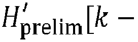


- The information from comparing, respectively, dL and


block 8, the final estimation may be


- Thus, in this case of double-sided extrapolation, the final estimate H est[k] of the value proportional to said one-way frequency domain channel response is based on comparison of the first metric distance dL, the second metric distance


- The functioning of the extrapolation from both below and above in frequency may be better understood with reference to
Figs 3b ,3c , and4 , illustrating a limitation of reconstruction without extrapolation. - With reference to
Fig. 3b , even though the jump atfrequency index 26 is corrected successfully,frequency index 7 was mistakenly phase reversed, as is evident from the apparent discontinuity of the otherwise smooth progression of the direction of the tangent of the resulting curve, due to that points small magnitude compared to its distance to the point corresponding to theprevious frequency index 6. Such a phenomenon may for example occur when experiencing deep fading at certain frequencies, due to multipath propagation.Fig. 3c shows that this discontinuity is present as well, in this example, after the transformation to compensate for the inherent phase advance. -
Fig. 4 is a close-up look of the area around the point corresponding tofrequency index 7 inFig. 3c and illustrates linear extrapolation according to the above for frequency index k = 7. - Shown with plus symbols and frequency indices are the transformed representations

- A phase reversal


frequency index 7 is marked 7'. In the same way, a phase reversal
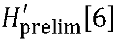
frequency index 6 is marked 6'. - Further, shown with an unfilled (white) circle is a prediction

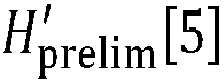

- Metric distances in the complex plane dL - between


- Since, in this example,
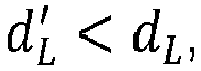
- Further, extrapolation from higher frequency is shown. The prediction


- Metric distances in the complex plane dH - between


- Thus, in this example,

frequency indices frequency index 7 in compensation. - Thus, with both


- Finally, in
block 10 ofFig. 3 , the distance between the first and the second radio signal transceiver may be determined based on the final estimates. E.g. an inverse fast Fourier transform (IFFT), as is known per se, can be used but also more advanced signal processing techniques typically referred to as super-resolution algorithms, as also are known per se, as described in, e.g.,
Schmidt: IEEE Transactions on Antennas and Propagation, Vol AP-34, No. 3, pp. 276-280, March 1986;
Sakar: IEEE Antennas and Propagation Magazine, Vol. 37, No. 1, pp. 48-55, February 1995;
Roy: IEEE Transactions on Acoustics, Speech, and Signal Processing, Vol. 37, No. 7, July 1989. - The reconstructed one-way frequency-domain channel response H[k] allows most ranging algorithms to mitigate more interference from multipath, as the order of the problem/number of components is reduced. In the presence of multipath, the number of components interfering with the estimation of the delay of the line-of-sight (LOS) component will be reduced and ranging and localization will be more accurate.
- A computer program product comprising a computer-readable medium may store computer-readable instructions such that when executed on a processing unit the computer program product will cause the processing unit to perform the method according to the above.
- The method may be performed in a processing unit, which may be arranged in a device A, B or C as discussed above.
- The processing unit may be implemented in hardware, or as any combination of software and hardware. At least part of the functionality of the processing unit may, for instance, be implemented as software being executed on a general-purpose computer. The system may thus comprise one or more processing units, such as a central processing unit (CPU), which may execute the instructions of one or more computer programs in order to implement desired functionality.
- The processing unit may alternatively be implemented as firmware arranged e.g. in an embedded system, or as a specifically designed processing unit, such as an Application-Specific Integrated Circuit (ASIC) or a Field-Programmable Gate Array (FPGA).
- The correlation properties for the one-way frequency domain channel response for adjacent frequencies will naturally vary depending on the exact environment. There may be a range of frequency step sizes where the method disclosed herein works increasingly well as the frequency stepping is reduced, but where no hard upper limit of applicability can be defined.
- The concept of coherence bandwidth is a statistical measurement that is approximately the maximum frequency interval over which two signals at two frequencies experience correlated amplitude fading. An approximation of the coherence bandwidth over which the amplitude correlation is lower than 0.5 is

m is the root mean square (RMS) delay spread (Goldsmith, Andrea. Wireless communications. Cambridge university press, 2005.) - According to a measurement campaign at 2.4GHz in a 7.8m-by-10m room where benches and laboratory equipment scatter around, the RMS delay spread ranges from 20ns to 30ns depending on the relative distance between Tx and Rx (Zepernick, H. J., & Wysocki, T. A. Multipath channel parameters for the indoor radio at 2.4 GHz ISM band. In 1999 IEEE 49th Vehicular Technology Conference, May 1999, Vol. 1, pp. 190-193). This indicates a coherence bandwidth in such an environment be around 8 MHz (with σT
m = 25ns). - A typical ranging and direction-finding system may operate in the ISM band with a frequency step in the order of 1 MHz. According to the above, this this frequency step is small enough that the one-way frequency domain channel responses are correlated.
- Additionally, the phase of frequency responses that are at different frequencies are correlated as well, because the slope of the phase along frequency is proportional to the distance between the initiator and reflector in a line-of-sight (LOS) channel. The amplitude coherency and phase coherency across frequency samples of the wireless channel when observed at every 1 MHz ensures that the complex frequency response rotates progressively rather than arbitrarily.
- In the following, results validating the channel reconstruction of the one-way frequency domain channel response according to the present disclosure, including the transformation and double-sided linear extrapolation as detailed above.
- Multi-path channels were generated by means of ray tracing. In the ray tracer, a 11m-by-7m meeting room without furniture was defined, as illustrated in
Fig. 5 . An initiator was put in one of the corners while the reflector was moved around the room at 112 distinct locations forming the shape of anArabic numeral 8. The scene is shown inFig. 5 . The simulation contained up to 3rd order reflections. Random phase offsets were selected uniformly randomly from 0 to 2π radians and added to the channel response each time the carrier frequency was switched. The phase offset was kept constant when switching the direction of transmission. White Gaussian noise was added such that the SNR per antenna was 20dB. - An indicator of reconstruction reliability was defined in the form of a reconstructed-channel quality indicator Q, describing the similarity between the reconstructed channel and the actual channel. It is defined by:

-
Figs 6a, 6b ,6c, and 6d respectively show the quality indicator Q for Rician-K values - One can see that for high K values, the channel reconstruction is flawless. If the Rician K value reduces, performance of the algorithm somewhat reduces, while still a good reconstruction is realized for a significant part of the channels.
- In the above the inventive concept has mainly been described with reference to a limited number of examples. However, as is readily appreciated by a person skilled in the art, other examples than the ones disclosed above are equally possible within the scope of the inventive concept, as defined by the appended claims.
- For example, the extrapolation can be done linearly, as exemplified in this disclosure, or in more sophisticated manners, e.g. using higher-order, non-linear extrapolation.
- Instead of calculating an average phase advance transformation compensating for the inherent phase advance between adjacent frequencies may be provided through a tracking algorithm.
Claims (15)
- A method for determining a distance between a first and a second radio signal transceiver, said method comprising:receiving (2) a first set of measurement results and a second set of measurement results, wherein the first set of measurement results is acquired by the first radio signal transceiver based on signals transmitted from the second radio signal transceiver and the second set of measurement results is acquired by the second radio signal transceiver based on signals transmitted from the first radio signal transceiver, the first set of measurement results being representable as comprising, for each of a plurality of frequencies, a measurement pair of a phase value and a signal strength value and the second set of measurement results being representable as comprising, for each of said plurality of frequencies, a phase value or optionally a measurement pair of a phase value and a signal strength value;calculating (4), for each frequency of said plurality of frequencies, a preliminary estimate of a value proportional to a one-way frequency domain channel response, based on the measurement results for said frequency from said first set of measurement results and the phase value, or optionally the measurement results for said frequency, from the second set of measurement results;calculating (5), for a frequency of said plurality of frequencies, a predicted estimate of a representation of said value proportional to said one-way frequency domain channel response, based on one or more estimates for one or more respective frequencies adjacent to said frequency,calculating (6a), a first metric distance between said predicted estimate for said frequency and a representation of said preliminary estimate for said frequency;calculating (6b) a second metric distance between said predicted estimate for said frequency and a phase reversal of said representation of said preliminary estimate for said frequency;determining (8), for said frequency, a final estimate of said value proportional to said one-way frequency domain channel response, based on a comparison of said first metric distance and said second metric distance, said final estimate being either a phase reversal of said preliminary estimate, or said preliminary estimate; anddetermining (10) the distance between the first and the second radio signal transceiver based on a plurality of such final estimates.
- The method of claim 1, wherein said predicted estimate is a representation of a said estimate for an immediately adjacent frequency.
- The method of claim 1, wherein said predicted estimate is an extrapolation from two or more said estimates for two or more respective adjacent frequencies to said frequency.
- The method of claim 3, said two or more respective adjacent frequencies to said frequency are lower than said frequency and said method further comprises:calculating a second predicted estimate of a said representation of a said value proportional to a said one-way frequency domain channel response, based on one or more estimates for said frequency and one or more respective frequencies adjacent to and higher than said frequency;calculating a third metric distance between said second predicted estimate and a said representation of a said preliminary estimate corresponding to said second predicted estimate; andcalculating a fourth metric distance between said second predicted estimate and a phase reversal of said representation of said preliminary estimate corresponding to said second predicted estimate,wherein said final estimate of said value proportional to said one-way frequency domain channel response is based on comparison of said first metric distance, said second metric distance, said third metric distance, and/or said fourth metric distance.
- The method of any one of claims 1-4, wherein each said representation of a respective quantity is the quantity itself.
- The method of any one of claims 1-4, wherein each said representation of a respective quantity is a frequency-dependent transformation compensating for an inherent phase advance between adjacent frequencies.
- The method of claim 6, wherein said transformation is calculated as an average phase advance between said plurality of frequencies.
- The method according to any one of claims 1-7, wherein said calculating (4) of said preliminary estimate of a value proportional to the one-way frequency domain channel response comprises:calculating an estimate of a value proportional to a two-way frequency domain channel response based on the measurements for said frequency from the first set of measurement results and the phase value, or optionally the measurements for said frequency, from the second set of measurement results; andcalculating said preliminary estimate proportional to the one-way frequency domain channel response based on said estimate of the value proportional to the two-way frequency domain channel response.
- The method according to any one of claims 1-8, wherein:each measurement pair of said measurement pairs is representable as a complex number, wherein the modulus of said complex number represents an amplitude corresponding to the signal strength value and the argument of said complex number represents the phase value; andsaid preliminary estimate and said final estimate each are representable by complex numbers, wherein the modulus of said complex number represents an amplitude response and the argument of said complex number represents a phase response.
- The method according to claim 9, wherein said second set of measurement results comprises, for each of said plurality of frequencies, said measurement pair and said calculating of the estimate of the value proportional to a two-way frequency domain channel response comprises, or is representable as comprising, multiplying the complex number representing said measurement pair from the first set of measurement results with the complex number representing the measurement pair from the second set of measurement results.
- The method according to any one of claims 9-10, wherein said calculating (4) of the preliminary estimate of the value proportional to the one-way frequency domain channel response based on the estimate of the value proportional to the two-way frequency domain channel response comprises, or is representable as comprising, taking a complex square root of the estimate proportional to the two-way frequency domain channel response.
- The method according to claim 11, wherein, when during said taking of the square root, a solution with the phase between -π/2 and π/2 is selected.
- The method according to any one of claims 1-12, wherein determining of the distance between the first and the second radio signal transceiver uses an algorithm based on IFFT and/or a super-resolution algorithm.
- A computer program product comprising a computer-readable medium storing computer-readable instructions such that when executed on a processing unit the computer program product will cause the processing unit to perform the method according to any one of the preceding claims.
- A radio signal transceiver configured to determine a distance to a second radio signal transceiver, said radio signal transceiver comprising:a measurement unit configured to acquire (2) a first set of measurement results based on signals transmitted from the second radio signal transceiver, the first set of measurement results being representable as comprising, for each of a plurality of frequencies, a measurement pair of a phase value and a signal strength value;a receiver configured to receive (2) a second set of measurement results acquired by the second radio signal transceiver based on signals transmitted from the first radio signal transceiver, the second set of measurement results being representable as comprising, for each of a plurality of frequencies, a phase value or optionally a measurement pair of a phase value and a signal strength value; anda processing unit configured to:calculate (4) for each frequency of said plurality of frequencies, a preliminary estimate of a value proportional to a one-way frequency domain channel response, based on the measurement results for said frequency from said first set of measurement results and the phase value, or optionally the measurement results for said frequency, from the second set of measurement results;calculate, for a frequency of said plurality of frequencies, a predicted estimate of a representation of said value proportional to said one-way frequency domain channel response, based on one or more estimates for one or more respective frequencies adjacent to said frequency;calculate a first metric distance between said predicted estimate for said frequency and a representation of said preliminary estimate for said frequency;calculate a second metric distance between said predicted estimate for said frequency and a phase reversal of said representation of said preliminary estimate for said frequency;determine (8), for said frequency, a final estimate of said value proportional to said one-way frequency domain channel response, based on a comparison of said first metric distance and said second metric distance, said final estimate being either a phase reversal of said preliminary estimate, or said preliminary estimate; anddetermine (10) the distance between the first and the second radio signal transceiver based on a plurality of such final estimates.
Priority Applications (3)
| Application Number | Priority Date | Filing Date | Title |
|---|---|---|---|
| EP19218751.6A EP3839562B1 (en) | 2019-12-20 | 2019-12-20 | Method for distance determination |
| US17/757,340 US12241957B2 (en) | 2019-12-20 | 2020-12-17 | Method for distance determination |
| PCT/EP2020/086842 WO2021123032A1 (en) | 2019-12-20 | 2020-12-17 | Method for distance determination |
Applications Claiming Priority (1)
| Application Number | Priority Date | Filing Date | Title |
|---|---|---|---|
| EP19218751.6A EP3839562B1 (en) | 2019-12-20 | 2019-12-20 | Method for distance determination |
Publications (2)
| Publication Number | Publication Date |
|---|---|
| EP3839562A1 true EP3839562A1 (en) | 2021-06-23 |
| EP3839562B1 EP3839562B1 (en) | 2024-09-18 |
Family
ID=69005269
Family Applications (1)
| Application Number | Title | Priority Date | Filing Date |
|---|---|---|---|
| EP19218751.6A Active EP3839562B1 (en) | 2019-12-20 | 2019-12-20 | Method for distance determination |
Country Status (3)
| Country | Link |
|---|---|
| US (1) | US12241957B2 (en) |
| EP (1) | EP3839562B1 (en) |
| WO (1) | WO2021123032A1 (en) |
Cited By (1)
| Publication number | Priority date | Publication date | Assignee | Title |
|---|---|---|---|---|
| EP4202491A1 (en) | 2021-12-23 | 2023-06-28 | Stichting IMEC Nederland | Multi-carrier phase difference distance estimation |
Families Citing this family (2)
| Publication number | Priority date | Publication date | Assignee | Title |
|---|---|---|---|---|
| CN115733565A (en) * | 2021-09-01 | 2023-03-03 | 维沃移动通信有限公司 | Detection method, device and equipment |
| US20250389834A1 (en) * | 2024-06-20 | 2025-12-25 | Qualcomm Incorporated | Round-trip phase ranging in the presence of deep fade |
Citations (3)
| Publication number | Priority date | Publication date | Assignee | Title |
|---|---|---|---|---|
| US20160178744A1 (en) | 2008-12-30 | 2016-06-23 | Atmel Corporation | Distance Measurement Between Two Nodes of a Radio Network |
| US20190187263A1 (en) * | 2017-12-20 | 2019-06-20 | Stichting Imec Nederland | Method for Distance Determination |
| EP3564707A1 (en) | 2018-05-04 | 2019-11-06 | Lambda: 4 Entwicklungen GmbH | Method and system for high resolution range and velocity measurements |
Family Cites Families (10)
| Publication number | Priority date | Publication date | Assignee | Title |
|---|---|---|---|---|
| US4757315A (en) * | 1986-02-20 | 1988-07-12 | The United States Of America As Represented By The Administrator Of The National Aeronautics And Space Administration | Method and apparatus for measuring distance |
| US6731908B2 (en) | 2001-01-16 | 2004-05-04 | Bluesoft, Inc. | Distance measurement using half-duplex RF techniques |
| US7680218B2 (en) | 2005-10-25 | 2010-03-16 | Telefonaktiebolaget Lm Ericsson (Publ) | Method and apparatus for communication channel estimation |
| US7872583B1 (en) | 2005-12-15 | 2011-01-18 | Invisitrack, Inc. | Methods and system for multi-path mitigation in tracking objects using reduced attenuation RF technology |
| US8094061B2 (en) * | 2007-02-22 | 2012-01-10 | Nec Corporation | Multiband transceiver and positioning system using the transceiver |
| DE102009060591A1 (en) * | 2008-12-30 | 2010-07-08 | Atmel Automotive Gmbh | Transmitter-receiver circuit and method for distance measurement between a first node and a second node of a radio network |
| EP3609021A1 (en) | 2015-10-08 | 2020-02-12 | PoLTE Corporation | Angle of arrival positioning system for tracking objects |
| EP3316534A1 (en) | 2016-10-27 | 2018-05-02 | Fraunhofer Gesellschaft zur Förderung der Angewand | Channel estimation of frequency sub bands |
| JP7004062B2 (en) | 2018-03-09 | 2022-01-21 | 日本電気株式会社 | Wireless device and channel prediction method |
| EP3564706A1 (en) | 2018-05-04 | 2019-11-06 | Lambda: 4 Entwicklungen GmbH | Method and system for high resolution range and velocity measurements |
-
2019
- 2019-12-20 EP EP19218751.6A patent/EP3839562B1/en active Active
-
2020
- 2020-12-17 US US17/757,340 patent/US12241957B2/en active Active
- 2020-12-17 WO PCT/EP2020/086842 patent/WO2021123032A1/en not_active Ceased
Patent Citations (4)
| Publication number | Priority date | Publication date | Assignee | Title |
|---|---|---|---|---|
| US20160178744A1 (en) | 2008-12-30 | 2016-06-23 | Atmel Corporation | Distance Measurement Between Two Nodes of a Radio Network |
| US20190187263A1 (en) * | 2017-12-20 | 2019-06-20 | Stichting Imec Nederland | Method for Distance Determination |
| EP3502736A1 (en) | 2017-12-20 | 2019-06-26 | Stichting IMEC Nederland | Method for distance determination |
| EP3564707A1 (en) | 2018-05-04 | 2019-11-06 | Lambda: 4 Entwicklungen GmbH | Method and system for high resolution range and velocity measurements |
Non-Patent Citations (7)
| Title |
|---|
| GOLDSMITH, ANDREA: "Wireless communications", 2005, CAMBRIDGE UNIVERSITY PRESS |
| PELKA MATHIAS ET AL: "Accurate radio distance estimation by phase measurements with multiple frequencies", 2014 INTERNATIONAL CONFERENCE ON INDOOR POSITIONING AND INDOOR NAVIGATION (IPIN), IEEE, 27 October 2014 (2014-10-27), pages 142 - 151, XP033218001, DOI: 10.1109/IPIN.2014.7275478 * |
| ROY, IEEE TRANSACTIONS ON ACOUSTICS, SPEECH, AND SIGNAL PROCESSING, vol. 37, no. 7, July 1989 (1989-07-01) |
| SAKAR, IEEE ANTENNAS AND PROPAGATION MAGAZINE, vol. 37, no. 1, February 1995 (1995-02-01), pages 48 - 55 |
| SCHMIDT, IEEE TRANSACTIONS ON ANTENNAS AND PROPAGATION, vol. AP-34, no. 3, March 1986 (1986-03-01), pages 276 - 280 |
| ZAND POURIA ET AL: "A high-accuracy phase-based ranging solution with Bluetooth Low Energy (BLE)", 2019 IEEE WIRELESS COMMUNICATIONS AND NETWORKING CONFERENCE (WCNC), IEEE, 15 April 2019 (2019-04-15), pages 1 - 8, XP033652153, DOI: 10.1109/WCNC.2019.8885791 * |
| ZEPERNICK, H. J.WYSOCKI, T. A.: "Multipath channel parameters for the indoor radio at 2.4 GHz ISM band", 1999 IEEE 49TH VEHICULAR TECHNOLOGY CONFERENCE, vol. 1, May 1999 (1999-05-01), pages 190 - 193, XP010341987, DOI: 10.1109/VETEC.1999.778044 |
Cited By (2)
| Publication number | Priority date | Publication date | Assignee | Title |
|---|---|---|---|---|
| EP4202491A1 (en) | 2021-12-23 | 2023-06-28 | Stichting IMEC Nederland | Multi-carrier phase difference distance estimation |
| US12313720B2 (en) | 2021-12-23 | 2025-05-27 | Stichting Imec Nederland | Multi-carrier phase difference distance estimation |
Also Published As
| Publication number | Publication date |
|---|---|
| WO2021123032A1 (en) | 2021-06-24 |
| US20230022613A1 (en) | 2023-01-26 |
| EP3839562B1 (en) | 2024-09-18 |
| US12241957B2 (en) | 2025-03-04 |
Similar Documents
| Publication | Publication Date | Title |
|---|---|---|
| US10928495B2 (en) | Method for distance determination | |
| US20240168147A1 (en) | Method and apparatus for determining location using phase difference of arrival | |
| US11184048B2 (en) | System and method for distance and velocity estimation in phase-based ranging | |
| US11555881B2 (en) | Locating method for localizing at least one object using wave-based signals and locating system | |
| EP2441300B1 (en) | Rf fingerprinting for location estimation | |
| US12241957B2 (en) | Method for distance determination | |
| US20110074633A1 (en) | Methods and Systems for Estimating Angle of Arrival | |
| US20110267223A1 (en) | System and Method for Resolving Ambiguity in Radar, Lidar, and Acoustic Systems | |
| KR100416026B1 (en) | Method and system for comparing measured radio frequency signal propagation characteristics in a wireless communication system | |
| US11693081B2 (en) | Method for estimating distance using wireless carrier signal phase measurement | |
| CN102203634A (en) | Method and system for tracking multipath suppression in objects using attenuation-reduced RF techniques | |
| EP4009075B1 (en) | Radio frequency distance determination | |
| CN112187316A (en) | Signal processing method, signal processing device, receiver and storage medium | |
| US12342312B2 (en) | Positioning measurements | |
| Helwa et al. | Bridging the performance gap between two-way and one-way CSI-based 5 GHz WiFi ranging | |
| US11953612B2 (en) | Ranging method | |
| US12494856B2 (en) | Method for detecting type of wireless channel and apparatus therefor | |
| Jiang et al. | For better CSI fingerprinting based localization: a novel phase sanitization method and a distance metric | |
| WO2023032901A1 (en) | Positioning system and positioning method | |
| Ventura et al. | Asymov: Integrated sensing and communications with asynchronous moving devices | |
| US20250216544A1 (en) | Phased-based ranging | |
| EP4465088A1 (en) | Phased-based ranging | |
| EP4283323B1 (en) | Communication device and method of operation | |
| EP4320759B1 (en) | Devices and methods for flexible channel measurement using splicing | |
| EP2348779B1 (en) | Bearing determination using signals transformed into frequency domain |
Legal Events
| Date | Code | Title | Description |
|---|---|---|---|
| PUAI | Public reference made under article 153(3) epc to a published international application that has entered the european phase |
Free format text: ORIGINAL CODE: 0009012 |
|
| STAA | Information on the status of an ep patent application or granted ep patent |
Free format text: STATUS: THE APPLICATION HAS BEEN PUBLISHED |
|
| AK | Designated contracting states |
Kind code of ref document: A1 Designated state(s): AL AT BE BG CH CY CZ DE DK EE ES FI FR GB GR HR HU IE IS IT LI LT LU LV MC MK MT NL NO PL PT RO RS SE SI SK SM TR |
|
| STAA | Information on the status of an ep patent application or granted ep patent |
Free format text: STATUS: REQUEST FOR EXAMINATION WAS MADE |
|
| RBV | Designated contracting states (corrected) |
Designated state(s): AL AT BE BG CH CY CZ DE DK EE ES FI FR GB GR HR HU IE IS IT LI LT LU LV MC MK MT NL NO PL PT RO RS SE SI SK SM TR |
|
| 17P | Request for examination filed |
Effective date: 20210629 |
|
| TPAC | Observations filed by third parties |
Free format text: ORIGINAL CODE: EPIDOSNTIPA |
|
| STAA | Information on the status of an ep patent application or granted ep patent |
Free format text: STATUS: EXAMINATION IS IN PROGRESS |
|
| 17Q | First examination report despatched |
Effective date: 20230209 |
|
| GRAP | Despatch of communication of intention to grant a patent |
Free format text: ORIGINAL CODE: EPIDOSNIGR1 |
|
| STAA | Information on the status of an ep patent application or granted ep patent |
Free format text: STATUS: GRANT OF PATENT IS INTENDED |
|
| INTG | Intention to grant announced |
Effective date: 20231208 |
|
| P01 | Opt-out of the competence of the unified patent court (upc) registered |
Effective date: 20240208 |
|
| GRAJ | Information related to disapproval of communication of intention to grant by the applicant or resumption of examination proceedings by the epo deleted |
Free format text: ORIGINAL CODE: EPIDOSDIGR1 |
|
| STAA | Information on the status of an ep patent application or granted ep patent |
Free format text: STATUS: EXAMINATION IS IN PROGRESS |
|
| INTC | Intention to grant announced (deleted) | ||
| GRAP | Despatch of communication of intention to grant a patent |
Free format text: ORIGINAL CODE: EPIDOSNIGR1 |
|
| STAA | Information on the status of an ep patent application or granted ep patent |
Free format text: STATUS: GRANT OF PATENT IS INTENDED |
|
| INTG | Intention to grant announced |
Effective date: 20240531 |
|
| GRAS | Grant fee paid |
Free format text: ORIGINAL CODE: EPIDOSNIGR3 |
|
| GRAA | (expected) grant |
Free format text: ORIGINAL CODE: 0009210 |
|
| STAA | Information on the status of an ep patent application or granted ep patent |
Free format text: STATUS: THE PATENT HAS BEEN GRANTED |
|
| AK | Designated contracting states |
Kind code of ref document: B1 Designated state(s): AL AT BE BG CH CY CZ DE DK EE ES FI FR GB GR HR HU IE IS IT LI LT LU LV MC MK MT NL NO PL PT RO RS SE SI SK SM TR |
|
| REG | Reference to a national code |
Ref country code: GB Ref legal event code: FG4D |
|
| REG | Reference to a national code |
Ref country code: CH Ref legal event code: EP |
|
| REG | Reference to a national code |
Ref country code: DE Ref legal event code: R096 Ref document number: 602019059025 Country of ref document: DE |
|
| REG | Reference to a national code |
Ref country code: IE Ref legal event code: FG4D |
|
| REG | Reference to a national code |
Ref country code: LT Ref legal event code: MG9D |
|
| PG25 | Lapsed in a contracting state [announced via postgrant information from national office to epo] |
Ref country code: NO Free format text: LAPSE BECAUSE OF FAILURE TO SUBMIT A TRANSLATION OF THE DESCRIPTION OR TO PAY THE FEE WITHIN THE PRESCRIBED TIME-LIMIT Effective date: 20241218 |
|
| PG25 | Lapsed in a contracting state [announced via postgrant information from national office to epo] |
Ref country code: GR Free format text: LAPSE BECAUSE OF FAILURE TO SUBMIT A TRANSLATION OF THE DESCRIPTION OR TO PAY THE FEE WITHIN THE PRESCRIBED TIME-LIMIT Effective date: 20241219 Ref country code: FI Free format text: LAPSE BECAUSE OF FAILURE TO SUBMIT A TRANSLATION OF THE DESCRIPTION OR TO PAY THE FEE WITHIN THE PRESCRIBED TIME-LIMIT Effective date: 20240918 |
|
| PG25 | Lapsed in a contracting state [announced via postgrant information from national office to epo] |
Ref country code: BG Free format text: LAPSE BECAUSE OF FAILURE TO SUBMIT A TRANSLATION OF THE DESCRIPTION OR TO PAY THE FEE WITHIN THE PRESCRIBED TIME-LIMIT Effective date: 20240918 |
|
| PG25 | Lapsed in a contracting state [announced via postgrant information from national office to epo] |
Ref country code: LV Free format text: LAPSE BECAUSE OF FAILURE TO SUBMIT A TRANSLATION OF THE DESCRIPTION OR TO PAY THE FEE WITHIN THE PRESCRIBED TIME-LIMIT Effective date: 20240918 |
|
| PG25 | Lapsed in a contracting state [announced via postgrant information from national office to epo] |
Ref country code: HR Free format text: LAPSE BECAUSE OF FAILURE TO SUBMIT A TRANSLATION OF THE DESCRIPTION OR TO PAY THE FEE WITHIN THE PRESCRIBED TIME-LIMIT Effective date: 20240918 |
|
| REG | Reference to a national code |
Ref country code: NL Ref legal event code: MP Effective date: 20240918 |
|
| PG25 | Lapsed in a contracting state [announced via postgrant information from national office to epo] |
Ref country code: RS Free format text: LAPSE BECAUSE OF FAILURE TO SUBMIT A TRANSLATION OF THE DESCRIPTION OR TO PAY THE FEE WITHIN THE PRESCRIBED TIME-LIMIT Effective date: 20241218 |
|
| PG25 | Lapsed in a contracting state [announced via postgrant information from national office to epo] |
Ref country code: RS Free format text: LAPSE BECAUSE OF FAILURE TO SUBMIT A TRANSLATION OF THE DESCRIPTION OR TO PAY THE FEE WITHIN THE PRESCRIBED TIME-LIMIT Effective date: 20241218 Ref country code: NO Free format text: LAPSE BECAUSE OF FAILURE TO SUBMIT A TRANSLATION OF THE DESCRIPTION OR TO PAY THE FEE WITHIN THE PRESCRIBED TIME-LIMIT Effective date: 20241218 Ref country code: LV Free format text: LAPSE BECAUSE OF FAILURE TO SUBMIT A TRANSLATION OF THE DESCRIPTION OR TO PAY THE FEE WITHIN THE PRESCRIBED TIME-LIMIT Effective date: 20240918 Ref country code: HR Free format text: LAPSE BECAUSE OF FAILURE TO SUBMIT A TRANSLATION OF THE DESCRIPTION OR TO PAY THE FEE WITHIN THE PRESCRIBED TIME-LIMIT Effective date: 20240918 Ref country code: GR Free format text: LAPSE BECAUSE OF FAILURE TO SUBMIT A TRANSLATION OF THE DESCRIPTION OR TO PAY THE FEE WITHIN THE PRESCRIBED TIME-LIMIT Effective date: 20241219 Ref country code: FI Free format text: LAPSE BECAUSE OF FAILURE TO SUBMIT A TRANSLATION OF THE DESCRIPTION OR TO PAY THE FEE WITHIN THE PRESCRIBED TIME-LIMIT Effective date: 20240918 Ref country code: BG Free format text: LAPSE BECAUSE OF FAILURE TO SUBMIT A TRANSLATION OF THE DESCRIPTION OR TO PAY THE FEE WITHIN THE PRESCRIBED TIME-LIMIT Effective date: 20240918 |
|
| REG | Reference to a national code |
Ref country code: AT Ref legal event code: MK05 Ref document number: 1725161 Country of ref document: AT Kind code of ref document: T Effective date: 20240918 |
|
| PG25 | Lapsed in a contracting state [announced via postgrant information from national office to epo] |
Ref country code: NL Free format text: LAPSE BECAUSE OF FAILURE TO SUBMIT A TRANSLATION OF THE DESCRIPTION OR TO PAY THE FEE WITHIN THE PRESCRIBED TIME-LIMIT Effective date: 20240918 |
|
| REG | Reference to a national code |
Ref country code: DE Ref legal event code: R026 Ref document number: 602019059025 Country of ref document: DE |
|
| PLBI | Opposition filed |
Free format text: ORIGINAL CODE: 0009260 |
|
| 26 | Opposition filed |
Opponent name: LAMBDA:4 ENTWICKLUNGEN GMBH Effective date: 20250219 |
|
| PG25 | Lapsed in a contracting state [announced via postgrant information from national office to epo] |
Ref country code: IS Free format text: LAPSE BECAUSE OF FAILURE TO SUBMIT A TRANSLATION OF THE DESCRIPTION OR TO PAY THE FEE WITHIN THE PRESCRIBED TIME-LIMIT Effective date: 20250118 Ref country code: PT Free format text: LAPSE BECAUSE OF FAILURE TO SUBMIT A TRANSLATION OF THE DESCRIPTION OR TO PAY THE FEE WITHIN THE PRESCRIBED TIME-LIMIT Effective date: 20250120 |
|
| PG25 | Lapsed in a contracting state [announced via postgrant information from national office to epo] |
Ref country code: SM Free format text: LAPSE BECAUSE OF FAILURE TO SUBMIT A TRANSLATION OF THE DESCRIPTION OR TO PAY THE FEE WITHIN THE PRESCRIBED TIME-LIMIT Effective date: 20240918 Ref country code: RO Free format text: LAPSE BECAUSE OF FAILURE TO SUBMIT A TRANSLATION OF THE DESCRIPTION OR TO PAY THE FEE WITHIN THE PRESCRIBED TIME-LIMIT Effective date: 20240918 |
|
| PG25 | Lapsed in a contracting state [announced via postgrant information from national office to epo] |
Ref country code: ES Free format text: LAPSE BECAUSE OF FAILURE TO SUBMIT A TRANSLATION OF THE DESCRIPTION OR TO PAY THE FEE WITHIN THE PRESCRIBED TIME-LIMIT Effective date: 20240918 |
|
| PG25 | Lapsed in a contracting state [announced via postgrant information from national office to epo] |
Ref country code: EE Free format text: LAPSE BECAUSE OF FAILURE TO SUBMIT A TRANSLATION OF THE DESCRIPTION OR TO PAY THE FEE WITHIN THE PRESCRIBED TIME-LIMIT Effective date: 20240918 Ref country code: AT Free format text: LAPSE BECAUSE OF FAILURE TO SUBMIT A TRANSLATION OF THE DESCRIPTION OR TO PAY THE FEE WITHIN THE PRESCRIBED TIME-LIMIT Effective date: 20240918 |
|
| PG25 | Lapsed in a contracting state [announced via postgrant information from national office to epo] |
Ref country code: PL Free format text: LAPSE BECAUSE OF FAILURE TO SUBMIT A TRANSLATION OF THE DESCRIPTION OR TO PAY THE FEE WITHIN THE PRESCRIBED TIME-LIMIT Effective date: 20240918 Ref country code: CZ Free format text: LAPSE BECAUSE OF FAILURE TO SUBMIT A TRANSLATION OF THE DESCRIPTION OR TO PAY THE FEE WITHIN THE PRESCRIBED TIME-LIMIT Effective date: 20240918 |
|
| PG25 | Lapsed in a contracting state [announced via postgrant information from national office to epo] |
Ref country code: SK Free format text: LAPSE BECAUSE OF FAILURE TO SUBMIT A TRANSLATION OF THE DESCRIPTION OR TO PAY THE FEE WITHIN THE PRESCRIBED TIME-LIMIT Effective date: 20240918 Ref country code: IT Free format text: LAPSE BECAUSE OF FAILURE TO SUBMIT A TRANSLATION OF THE DESCRIPTION OR TO PAY THE FEE WITHIN THE PRESCRIBED TIME-LIMIT Effective date: 20240918 |
|
| PLAX | Notice of opposition and request to file observation + time limit sent |
Free format text: ORIGINAL CODE: EPIDOSNOBS2 |
|
| PG25 | Lapsed in a contracting state [announced via postgrant information from national office to epo] |
Ref country code: MC Free format text: LAPSE BECAUSE OF FAILURE TO SUBMIT A TRANSLATION OF THE DESCRIPTION OR TO PAY THE FEE WITHIN THE PRESCRIBED TIME-LIMIT Effective date: 20240918 |
|
| PG25 | Lapsed in a contracting state [announced via postgrant information from national office to epo] |
Ref country code: DK Free format text: LAPSE BECAUSE OF FAILURE TO SUBMIT A TRANSLATION OF THE DESCRIPTION OR TO PAY THE FEE WITHIN THE PRESCRIBED TIME-LIMIT Effective date: 20240918 |
|
| REG | Reference to a national code |
Ref country code: CH Ref legal event code: PL |
|
| PG25 | Lapsed in a contracting state [announced via postgrant information from national office to epo] |
Ref country code: LU Free format text: LAPSE BECAUSE OF NON-PAYMENT OF DUE FEES Effective date: 20241220 |
|
| GBPC | Gb: european patent ceased through non-payment of renewal fee |
Effective date: 20241220 |
|
| PG25 | Lapsed in a contracting state [announced via postgrant information from national office to epo] |
Ref country code: SE Free format text: LAPSE BECAUSE OF FAILURE TO SUBMIT A TRANSLATION OF THE DESCRIPTION OR TO PAY THE FEE WITHIN THE PRESCRIBED TIME-LIMIT Effective date: 20240918 |
|
| REG | Reference to a national code |
Ref country code: BE Ref legal event code: MM Effective date: 20241231 |
|
| PG25 | Lapsed in a contracting state [announced via postgrant information from national office to epo] |
Ref country code: GB Free format text: LAPSE BECAUSE OF NON-PAYMENT OF DUE FEES Effective date: 20241220 Ref country code: BE Free format text: LAPSE BECAUSE OF NON-PAYMENT OF DUE FEES Effective date: 20241231 |
|
| PG25 | Lapsed in a contracting state [announced via postgrant information from national office to epo] |
Ref country code: FR Free format text: LAPSE BECAUSE OF NON-PAYMENT OF DUE FEES Effective date: 20241231 |
|
| PG25 | Lapsed in a contracting state [announced via postgrant information from national office to epo] |
Ref country code: CH Free format text: LAPSE BECAUSE OF NON-PAYMENT OF DUE FEES Effective date: 20241231 |
|
| PG25 | Lapsed in a contracting state [announced via postgrant information from national office to epo] |
Ref country code: IE Free format text: LAPSE BECAUSE OF NON-PAYMENT OF DUE FEES Effective date: 20241220 |
|
| PLBB | Reply of patent proprietor to notice(s) of opposition received |
Free format text: ORIGINAL CODE: EPIDOSNOBS3 |
|
| PGFP | Annual fee paid to national office [announced via postgrant information from national office to epo] |
Ref country code: DE Payment date: 20251126 Year of fee payment: 7 |