EP3839467A1 - Microfluidic or millifluidic chip comprising a pressure sensing unit using colour-switching hydrogels - Google Patents
Microfluidic or millifluidic chip comprising a pressure sensing unit using colour-switching hydrogels Download PDFInfo
- Publication number
- EP3839467A1 EP3839467A1 EP19306702.2A EP19306702A EP3839467A1 EP 3839467 A1 EP3839467 A1 EP 3839467A1 EP 19306702 A EP19306702 A EP 19306702A EP 3839467 A1 EP3839467 A1 EP 3839467A1
- Authority
- EP
- European Patent Office
- Prior art keywords
- microfluidic
- pressure
- chip
- millifluidic
- fluid
- Prior art date
- Legal status (The legal status is an assumption and is not a legal conclusion. Google has not performed a legal analysis and makes no representation as to the accuracy of the status listed.)
- Granted
Links
Images
Classifications
-
- G—PHYSICS
- G01—MEASURING; TESTING
- G01L—MEASURING FORCE, STRESS, TORQUE, WORK, MECHANICAL POWER, MECHANICAL EFFICIENCY, OR FLUID PRESSURE
- G01L9/00—Measuring steady of quasi-steady pressure of fluid or fluent solid material by electric or magnetic pressure-sensitive elements; Transmitting or indicating the displacement of mechanical pressure-sensitive elements, used to measure the steady or quasi-steady pressure of a fluid or fluent solid material, by electric or magnetic means
- G01L9/0041—Transmitting or indicating the displacement of flexible diaphragms
- G01L9/0076—Transmitting or indicating the displacement of flexible diaphragms using photoelectric means
-
- G—PHYSICS
- G01—MEASURING; TESTING
- G01L—MEASURING FORCE, STRESS, TORQUE, WORK, MECHANICAL POWER, MECHANICAL EFFICIENCY, OR FLUID PRESSURE
- G01L9/00—Measuring steady of quasi-steady pressure of fluid or fluent solid material by electric or magnetic pressure-sensitive elements; Transmitting or indicating the displacement of mechanical pressure-sensitive elements, used to measure the steady or quasi-steady pressure of a fluid or fluent solid material, by electric or magnetic means
- G01L9/0041—Transmitting or indicating the displacement of flexible diaphragms
- G01L9/0076—Transmitting or indicating the displacement of flexible diaphragms using photoelectric means
- G01L9/0077—Transmitting or indicating the displacement of flexible diaphragms using photoelectric means for measuring reflected light
-
- G—PHYSICS
- G01—MEASURING; TESTING
- G01L—MEASURING FORCE, STRESS, TORQUE, WORK, MECHANICAL POWER, MECHANICAL EFFICIENCY, OR FLUID PRESSURE
- G01L11/00—Measuring steady or quasi-steady pressure of a fluid or a fluent solid material by means not provided for in group G01L7/00 or G01L9/00
- G01L11/02—Measuring steady or quasi-steady pressure of a fluid or a fluent solid material by means not provided for in group G01L7/00 or G01L9/00 by optical means
-
- G—PHYSICS
- G01—MEASURING; TESTING
- G01L—MEASURING FORCE, STRESS, TORQUE, WORK, MECHANICAL POWER, MECHANICAL EFFICIENCY, OR FLUID PRESSURE
- G01L19/00—Details of, or accessories for, apparatus for measuring steady or quasi-steady pressure of a fluent medium insofar as such details or accessories are not special to particular types of pressure gauges
- G01L19/0007—Fluidic connecting means
- G01L19/0046—Fluidic connecting means using isolation membranes
-
- G—PHYSICS
- G01—MEASURING; TESTING
- G01L—MEASURING FORCE, STRESS, TORQUE, WORK, MECHANICAL POWER, MECHANICAL EFFICIENCY, OR FLUID PRESSURE
- G01L27/00—Testing or calibrating of apparatus for measuring fluid pressure
- G01L27/002—Calibrating, i.e. establishing true relation between transducer output value and value to be measured, zeroing, linearising or span error determination
-
- G—PHYSICS
- G01—MEASURING; TESTING
- G01L—MEASURING FORCE, STRESS, TORQUE, WORK, MECHANICAL POWER, MECHANICAL EFFICIENCY, OR FLUID PRESSURE
- G01L7/00—Measuring the steady or quasi-steady pressure of a fluid or a fluent solid material by mechanical or fluid pressure-sensitive elements
- G01L7/02—Measuring the steady or quasi-steady pressure of a fluid or a fluent solid material by mechanical or fluid pressure-sensitive elements in the form of elastically-deformable gauges
- G01L7/026—Measuring the steady or quasi-steady pressure of a fluid or a fluent solid material by mechanical or fluid pressure-sensitive elements in the form of elastically-deformable gauges with optical transmitting or indicating means
Definitions
- each lower cavity may be connected to an in and outlet to circulate buffer fluid in the lower cavity such as to keep the gel immersed in the buffer fluid.
- a sixth object of the present invention is a method for a direct and contact-free measuring of a local pressure of a fluid circulating in a microfluidic circuit, said method comprising the following steps:
- a microfluidic chip according to the first embodiment is schematically represented, which comprises a microfluidic circuit 2 with an embedded flow channel 21 through which a fluid circulates and along which the fluid flow pressure is to be measured, and twelve separable pressure sensing units 4, which are represented in FIG. 1 .
Landscapes
- Physics & Mathematics (AREA)
- General Physics & Mathematics (AREA)
- Measuring Fluid Pressure (AREA)
- Micromachines (AREA)
Abstract
Description
- Various example embodiments relate to microfluidic or millifluidic chips comprising at least one pressure sensing unit able to measure a fluid flow pressure.
- The widening applications of microfluidic devices have increased the need for reliable pressure sensing in those systems. Pressure sensing in such small fluidic circuits, however, is complicated by specific challenges stemming from the design of microfluidic chips. The lab-on-a-chip layout, first, requires that the sensor be fully integrable to the chip, and so most commonly to PDMS architectures. The sensitivity of the sensor is a second challenge, given that the pressure changes along short fluid sections can be minute.
- Several methods have been proposed to overcome these difficulties, which rely on soft sensing elements that deform under pressure. This deformation is then usually measured via electric methods (piezoelectric pillars[1], conductive liquid circuits[2], conductive inflating membrane[3]). Such methods require that the microfluidic chip is wired to external electrical apparatuses, which may not be convenient. Optical methods for the detection of the deformation of sensing elements have been proposed, and overcome this drawback: deformation of an optical grating[4], interference pattern in a deformed cavity[5], light focusing through an inflating membrane[6], or, very recently, nanostructured photonic inflating membranes[7].
- All those methods enable remote sensing of the fluid pressure, but the soft deforming element is in all cases directly coupled to the flow channel. The deformation of the soft element, necessary for the pressure measurement thus changes the flow geometry. This change in flow geometry in return modified the pressure distribution in the flow channel. The pressure sensing thus modifies the fluid pressure it is supposed to measure.
- The one proposed by Orth et al. [6] stands out as being the only method in which the sensing element is decoupled from the flow path of the fluid: therefore, the deformation of the sensor does not modify the geometry of the channel in which the fluid flows.
- This is a large advantage compared to the other methods described above. The method described in [6] uses the deformation of circular membranes under an applied pressure for pressure sensing with the membrane deformation being proportional to the applied pressure. To quantify the membrane deformation a reflection method is used, where the size of a bright spot of the captured image is linked to the membrane deformation and thus the applied pressure via a calibration step. The calibration is very sensitive to smallest changes, for example in the angle of the illumination or image capture, modifying the result. In addition, the measure is localised to one spot and as a consequence the resolution of the method remains limited and restricted to pressures above 10 kPa. The method proposed there relies on a robust calibration where a change in colour can directly be linked to an applied pressure and in addition a spatial average can be made over the colour displayed in the sensing unit leading to a much-improved resolution and access to smaller pressures (i.e. down to 2 kPa) compared to the methods mentioned above.
- In order to solve the previously mentioned drawbacks, the applicant has developed a first embodiment of a microfluidic or millifluidic chip comprising a microfluidic circuit with an embedded flow channel through which a fluid circulates and along which the fluid flow pressure is to be measured, and at least one separable pressure sensing unit that is positioned remotely from said main flow channel.
- More particularly, a first object of the invention according to the first embodiment consists in a separable sensing unit able to measure a fluid pressure, characterized in that it comprises two layers made of a liquid-tight material (for instance made of moulded PDMS or glass) and a membrane,
wherein one at least of said two layers is made of a material that is also light transparent,
wherein said membrane is impermeable to the fluid circulating in the channel and is able to deform under the pressure exerted by the fluid,
wherein said layers and said membrane are arranged according to the following configuration: - one layer is a top layer comprising an upper cavity,
- another layer that is a bottom layer comprising one lower cavity formed at its surface and facing the upper cavity of said top layer, said lower cavity containing a slab of a photonic hydrogel immersed in an aqueous buffer solution,
- said membrane separates the top layer from the bottom layer.
- The two layers of the separable sensing unit may be made of two moulded PDMS layers, obtained by standard soft lithography techniques [9].
- A second object of the invention according to the first embodiment consists in the above-mentioned microfluidic or millifluidic chip, and at least one separable pressure sensing unit according to the first object of the invention and positioned remotely from the main flow channel, at a distance so that the upper cavity of the pressure sensing unit is connected to the main flow channel via a side channel.
- According to a second embodiment of the invention, the applicant has developed a third object consisting in microfluidic or millifluidic chip comprising:
- a microfluidic circuit with an embedded flow channel through which a fluid circulates and along which the fluid flow pressure is to be measured, and
- at least one integrated pressure sensing unit able to measure the fluid flow pressure at a position along said main flow channel,
- one layer is a top layer in which the main flow channel is embedded at a surface of the top layer facing
- another layer that is a bottom layer comprising one lower cavity formed at its surface and containing a slab of a photonic hydrogel immersed in an aqueous buffer solution.
- In the same manner as the separable pressing unit of the first embodiment, the two layers of the microfluidic or millifluidic chip according to the second embodiment may be made of two moulded PDMS layers, obtained by standard soft lithography techniques[9].
- The microfluidic or millifluidic chip according to the first or second embodiments of the present invention enable local pressure measurements along any microfluidic fluid path. The sensing unit itself is based on the deformation of the membrane by a volume of the sensed fluid. This deformation causes the compression of an underlying slab of photonic hydrogel in the lower cavity, which changes colour in response to the deformation.
- Advantageously, in the microfluidic or millifluidic chip according to the first and second embodiments of the present invention, the photonic hydrogel may be a soft photonic hydrogel.
- By soft photonic hydrogel, it is meant in the present application a photonic hydrogel the Young's modulus of which is comparable to the pressure to be measured, for example, typically in the order of 1 to 100 kPa.
- In the frame of the present invention, the soft photonic hydrogel described in the scientific publication of Yue, Y. et al.[8] may be used, since it can be actuated under very small compressive stress, exhibits an ultrafast response time and has high spatial resolution. This excellent space-time resolution allows the measurement of small pressures in microfluidic devices.
- Advantageously, the microfluidic or millifluidic chip according to the first and second embodiments of the present invention may comprise a plurality of sensing units positioned at different location along the main flow channel, wherein the sensing units may present different or same sizes.
- Advantageously, in the microfluidic or millifluidic chip according to the first and second embodiments of the present invention, each upper cavity is cylindrical in shape with a diameter of 0.1 to 10 mm, and preferably of 1 mm to 4 mm.
- Advantageously, in the microfluidic or millifluidic chip according to the first and second embodiments of the present invention, each upper cavity may be connected to an outlet opposite to the main channel.
- Advantageously, in the microfluidic or millifluidic chip according to the first and second embodiments of the present invention, each lower cavity may be connected to an in and outlet to circulate buffer fluid in the lower cavity such as to keep the gel immersed in the buffer fluid.
- Advantageously, in the microfluidic or millifluidic chip according to the first and second embodiments of the present invention, the top layer and the bottom layer may be made of moulded PDMS, plastic material or glass.
- A fourth object of the present invention is a method for a direct and contact-free measuring of a local pressure of a fluid circulating in a microfluidic circuit, said method comprising the following steps:
- A. providing a microfluidic or millifluidic chip according to the second embodiment,
- B. imaging the photonic hydrogel contained in the lower cavity of the pressing unit of said microfluidic chip with a camera.
- Step B of hydrogel imaging with the camera can be performed by a reflective observation of the pressing unit.
- A fifth object of the present invention consists in the use of the method according to the fourth object of the invention for the measurement of a dynamic pressure as low as 2 kPa (20 mbar) with a resolution below 50 Pa (5 mbar).
- A sixth object of the present invention is a method for a direct and contact-free measuring of a local pressure of a fluid circulating in a microfluidic circuit, said method comprising the following steps:
- A. providing a microfluidic or millifluidic chip according to the first embodiment or to the second embodiment;
- B. imaging the photonic hydrogel contained in the lower cavity of the pressing unit of said microfluidic chip with a camera.
- Step B of hydrogel imaging with the camera can be performed by a reflective observation of the pressing unit.
- Yet another object of the invention consists in the use of the method according to the sixth object of the invention for the measurement of a static pressure as low as 2 kPa (20 mbar) with a resolution below 50 Pa (5 mbar).
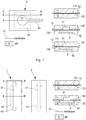
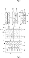
- Other innovative features and advantages of the invention will emerge from a reading of the following description followed by way of indication and in no way imitatively, with reference to the accompanying drawings, in which the figures illustrate schematically examples of implementation of the chips according to the invention. The figures are presented below:
- ▪
FIG.1 shows a schematic top view of asensing unit 4 to the first embodiment, and three schematic cross-sectional views along lines (AA'), (BB') and (CC') (drawn on the top view), respectively; - ▪
FIG.2 comprises schematic views of a microfluidic chip according to the second embodiment: a top view and its corresponding bottom view, together with two side views taken along lines A-A' and B-B' respectively (drawn on the bottom view); - ▪
FIG.3 comprises schematic views of a microfluidic chip according to the first embodiment of the invention comprisingseveral sensing units 4 ofFIG. 1 : a top view and its corresponding bottom view, together with three side views taken along lines A-A, B-B' and C-C' respectively (drawn on the bottom view). - ▪
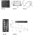
FIG.4 shows the calibration of a pressure sensing unit (4):- ∘
FIG. 4a shows the response of the pressure sensors under uniform and static pressure loading: top view of an array of sensors (4). The upper cavities are circular cavities ofheight 100 microns anddiameter 4 mm connected to a uniform and static pressure via a channel (43). Colour images are taken with a camera in reflection using white light and are shown for increasing pressure (in mbar) from 0 to 100 mbar, i.e. from 0 to 10 kPa∘ ; - ∘
FIG. 4B is the hue-value profile across the diameter of a sensor (4th sensor from the left, pressure increases from 0 to 140 mbar, i.e from 0 to 14 kPa); - ∘
FIG. 4C is a calibration curve: hue-value as a function of the applied pressure.
- ∘
- ▪
FIG.5 shows the realisation of amicrofluidic circuit 1 corresponding to the sketch displayed onFig. 3 (FIG 5a ) and, inFIG. 5b , the response of thepressure sensors 4 under the steady flow of water at 50 µL/min or imposed pressure difference between the in- and outlet of the channel 21 (bottom to top: 50 mbar, 50µL/min, 100 mbar, 150 mbar); inset: top view of the sensors at a steady flow of 50 µL/min. - ▪
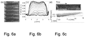
FIG.6 shows the realisation of amicrofluidic circuit 1 corresponding to the sketch displayed onFIG. 2 (FIG 6a ) and, inFIG 6b , the local hue-value profile for increasing pressures.FIG. 6c shows the non-uniform pressure as imposed by a steady flow of liquid: visual information (top) and reconstruction of the local pressure using the calibration curve fromFig.4(c) (bottom). - For clarity, the identical or similar elements are marked by identical signs on all the figures.
- The figures and the following description illustrate specific exemplary embodiments of the invention. It will thus be appreciated that those skilled in the art will be able to devise various arrangements that, although not explicitly described or shown herein, embody the principles of the invention and are included within the scope of the invention.
- Furthermore, any examples described herein are intended to aid in understanding the principles of the invention and are to be construed as being without limitation to such specifically recited examples and conditions. As a result, the invention is not limited to the specific embodiments or examples described below, but by the claims and their equivalents.
- In the following description, well-known functions or constructions by the person skilled in the art are not described in detail since they would obscure the invention in unnecessary detail.
- In the following description, the figures are commented on in detail in the examples and serve as a basis for them.
- In
FIG.3 , a microfluidic chip according to the first embodiment is schematically represented, which comprises amicrofluidic circuit 2 with an embeddedflow channel 21 through which a fluid circulates and along which the fluid flow pressure is to be measured, and twelve separablepressure sensing units 4, which are represented inFIG. 1 . - The
main flow channel 21 is a straight channel having a length L and square cross-section. - Each
sensing unit 4, as shown inFIG. 1 , comprises twolayers transparent PDMS membrane 13 that is able to deform under the pressure exerted by the fluid. - The
top layer 11 comprises theflow channel 21 connected to 12 circularupper cavities 41, connected to the flow channel via a narrow microfluidic channel 43 (width 50 microns). 6 upper cavities ofdiameter 4 mm are arranged on one side and 6 of diameter 1mm on the other side. Thebottom layer 12 contains two large squarelower cavities 42 containing a slab of thephotonic gel 6 of thickness 200 µm. - The preparation of the photonic gel is described in example 3.
- The height of the lower cavity closely matches the thickness of the gel. These lower cavities are sufficiently long to each completely cover 6 upper cavities. The two lower cavities are each connected to an in- and out-let allowing to circulate an aqueous buffer to assure the gel remains always immersed into the latter.
- Each upper cavity reposing on the membrane and the lower cavity containing the hydrogel represents a pressure sensing unit 4: the membrane deforms under the pressure in the upper cavity and compresses the photonic gel in the lower cavity. Under this deformation the gel changes colour.
- Each upper cavity is also connected to an
outlet 5 opposite of itsside channel 43. This outlet is left open during filling of the device (flowchannel 21 and upper cavity 41), and then closed for the experiments so that only the ends of themain flow channel 21 remain connected to fluid sources during normal operation of the device. -
FIG.5a shows the realisation of themicrofluidic circuit 1 corresponding to the sketch displayed onFIG. 3 . InFIG. 5a , themicrofluidic channel 21 is of square cross-section with width and height being 100 µm. It is connected to the 12upper cavities 41 arranged on both sides of the microchannel vianarrow channels 43 ofwidth 50 µm andheight 100 µm. 6 upper cavities have a diameter of 4 mm and 6 have a diameter of 1mm, all upper cavities have a height of 100 µm. Allupper cavities 41 are connected to an outlet opposite thechannel 43. The microfluidic channel as well as the upper cavities together with the outlets and the connecting channels are comprised in the upper layer. On the bottom of theupper layer 11 thePDMS membrane 13 separates the latter from thebottom layer 12. The PDMS membrane is ofthickness 100 µm. In thebottom layer 2lower cavities 42 are positioned below the arrays ofupper cavities 41. and are sufficiently wide (5 mm and 2 mm respectively) and long (20 mm) to completely cover the array of small and large cavities respectively. Their height is of 200 µm. Two slabs of photonic gel of thickness 200 µm are positioned in the lower cavities and closely fill the latter, except for a small gap on both sides allowing for lateral expansion once the gel is compressed from above. The lower cavities are connected to in and outlets to circulate buffer fluid such as to keep the slab of gel completely immersed at all times. - After calibration, as described in Example 4, the microfluidic chip can be used for local pressure sensing in flowing liquids (for example water).
- It was first tested by imposing a steady flow of water (flow rate: 50 µL/min) in the straight channel, and leaving the outlet open to the atmosphere. The response of the large sensors (
upper cavities 4 mm in diameter) to this flow is shown in the inset ofFig. 5b . A pressure gradient is visible along the channel. Note that the pressure at the last sensing location is not large enough to actuate the last sensor. Using calibration curves linking the observed colour to the applied pressure (see example 4) the pressure profile in the channel is obtained and is plotted with blue dots inFig.5b . The obtained profile is linear, as expected, and gives a total pressure drop of about 50 mbar, which is in very good agreement with the 47 mbar drop expected from the hydraulic resistance of the channel[9]. The linearity of the measured pressure profile under steady flow has been checked over a wider range by imposing a constant pressure at the inlet (the outlet remaining at atmospheric pressure). - The measured pressure response is shown in
Fig.5b for 3 imposed pressure drops. All profiles are linear as expected. At small pressure drops, the sensors closer to the outlet cannot be used as explained above. For very large pressure drops, the large sensors saturate (see calibration example 4). The small sensors can however provide complementary information (see calibration example 4) and were used for the highest data point at pressure drop of 150 mbar. - In
FIG.2 , a microfluidic chip according to the second embodiment is schematically represented, which comprises a microfluidic circuit with an embeddedflow channel 21 through which a fluid circulates and along which the fluid flow pressure is to be measured, and one integratedpressure sensing unit 4 able to measure the fluid flow pressure along themain flow channel 21. - This microfluidic chip comprises two moulded PDMS
transparent layers transparent PDMS membrane 13 that is able to deform under the pressure exerted by the fluid. The two moulded PDMS layers 11, 12 and themembrane 13 are arranged as follows: - one
layer 11 is a top layer in which themain flow channel 21 is embedded at asurface 110 of thetop layer 11 facing - the
other layer 12 that is a bottom layer comprising at least onelower cavity 42 formed at itssurface 120 and containing a slab of aphotonic hydrogel 6 immersed in a aqueous buffer solution. The preparation of thephotonic hydrogel 6 is described in example 3, - the
membrane 13 resting on thegel slab 6 separates thetop layer 11 from thebottom layer 12, and thus the flow channel from thelower cavity 42. - The
lower cavity 42 containing thephotonic gel 6 and the part of themembrane 13 covering thelower cavity 41 form anintegrated sensing unit 4. In the embodiment shown inFIG 1A , thelower cavity 42 is positioned so as to be placed directly themain flow channel 21. -
FIG.6 shows the realisation of amicrofluidic circuit 1 corresponding to the sketch displayed onFig. 2 (FIG 6a ) having a microfluidic circuit with an embeddedflow channel 21 through which a fluid circulates and along which the fluid flow pressure is to be measured, and one rectangular lower cavity able to measure the fluid flow pressure along themain flow channel 21. The main flow channel is a straight channel with a length L of 20 mm and square cross-section of width w = 100 µm and height h=100 µm. The flow channel is separated from the rectangularlower cavity 42 by a transparent PDMS membrane ofthickness 100µm 13. The lower cavity has a height of 200 µm and is large enough to completely cover themicrofluidic channel 21.FIG. 6A also shows top views taken with a camera in reflection using white light are shown for uniform pressure loading, with pressures increasing from top to bottom: 0 mbar, 25 mbar, 35 mbar, 45 mbar, 55 mbar and 70 mbar. - On
FIG 6B the hue-value profiles are shown for cross-sections along the channel thickness for different imposed static pressures. Those measurements can be used for calibration of the device (see example 4). -
FIG. 6C shows a non-uniform pressure profile as imposed by a steady flow of liquid: visual information (top) hue values (bottom). Using a calibration curve (see example 4) these hue values can be converted into local pressure measurements. - The pressure sensing gel is fabricated similarly to a previously reported lamellar sheet hydrogel [12]. It consists of uniaxially aligned reflective bilayers of PDGI (homo-polymerized poly(dodecyl glyceryl itaconate)) and a chemically crosslinked elastic hydrogel matrix of PAAm (polyacrylamide). A large sheet of soft PDGI/PAAm hydrogel with this lamellar bilayer structure parallel to the sheet surface was fabricated by slightly modifying the procedure described by Haque et. al. [12]. Briefly, a polymerization chamber is made of two parallel glass plates separated by 0.1 mm-thick silicone spacers. The reaction chamber possesses an inlet hole to be filled with the precursor solution (aqueous mixture of 0.1 M DGI, 0.0025 mM SDS, 2.0 M AAm, 2mM crosslinker and 2 mM photo-initiator) and an outlet hole connected to an automatic suction pump by a polyethylene tube. Prior to the polymerization, the precursor solution is sucked out of the chamber causing strong shear in the narrow gap between the two glass plates and thousands of lamellar bilayers of self-assembled DGI are formed, perfectly aligned in one direction parallel to the surface of glass substrate. In order to get stable PDGI bilayers in the hydrogel, this step is followed by a rapid polymerization by exposing the reaction chamber to UV light (365 nm) at 50°C for 8h under an inert Ar atmosphere. After polymerization, PDGI bilayers are trapped inside PAAm matrix. The PDGI/PAAm gels synthesized in this way are swollen in bi-distilled water for one week with regular freshwater replacement to avoid residuals. To further reduce the moduli of the equilibrium swollen PDGI/PAAm in a 2nd step, the parent PDGI/PAAm gels of 100 µm-thick were hydrolyzed using a modified procedure that was described previously by Yue et. al. (8). The parent gels were soaked in 1M KOH(aq) aqueous solution for 30 min, followed by heating in an incubator at 50°C for 5 min. The process of hydrolysis partially changes the amide functional groups (PAAm) of the parent PAAm hydrogel layers to sodium carboxylate groups (PAAc-Na). The obtained hydrogel, which contains partially hydrolyzed PAAm (PAAcNa), was then extensively washed several times with deionized water for achieving an equilibrium swelling state. The softness of this hydrolyzed PDGI/PAAm gel is controlled (modulus of 5 to 100 mbar) by maintaining the pH of the water. To be used as micro-fluidic pressure sensors the soft photonic hydrogel of thickness 140 µm were maintained in a buffer solution at pH = 6.92 using 0.2 M KOH(aq) and 0.2 M KH2PHO4(aq).
- The multilayer structure of the soft photonic hydrogel selectively diffracts visible light, so that it appears coloured under reflective white illumination. The gel diffracts longer wavelengths in its undeformed state (red colour), and shorter wavelengths when compressed (gradual shift to blue colour).
The response curve of such a photonic gel in terms of the reflected wavelength λ, measured with a spectrometer, as a function of a pressure P uniformly applied to the gel has already been presented in [8]. For pressure-sensing applications, we measure and quantify the colour-switching of the gel with a simpler equipment such as a colour camera and illumination in reflection with white light via a calibration step. This calibration method detailed here is used for the examples 1 and 2 presented above. -
Fig. 4 a shows the realisation of severalpressure sensing units 4 as described onFig. 1 integrated into a microfluidic device as shown onFig 3 and as discussed in example 1. Theupper cavities 41 have a radius of 4mm and are separated from the lower cavity by a PDMS membrane ofthickness 100 µm. The thickness of the slab ofgel 6 positioned in the lower cavity is 200 µm. The gel is immersed in an aqueous buffer solution. The lower cavity is rectangular and completely covers the upper cavities. A static pressure is applied to the pressure sensing units via theinlets 43. This pressure is increased stepwise and a colour image of the sensors is taken for each pressure value. Examples of pictures for increasing pressure from top to bottom (0 mbar to 100mbar) are shown onFig. 4a . At zero applied pressure, thegel strip 6 in thelower cavity 42 is of uniform red colour. When the pressure in theupper cavities 41 is increased, themembrane 13 presses on the gel, making it locally compressed: circular spots appear on the gel strip, which shift towards blue colours as the pressure is increased. - The colour on the pictures taken by the camera needs to be quantified. To do so, we use a grayscale intensity map of the hue-value H (Hue-Saturation-Value colour model). The diffracted light is monochromatic, which is why the H value is a good proxy for the measure of the wavelength. We will thus quantify the colour response of the gel with the hue-value H of the images acquired with a colour camera, under reflected white lighting.
- Because of the circular shape of the
upper cavity 41, the hue profile is axisymmetric. To get optimal resolution, we thus detect the centre of each cavity and average the H value over the azimuthal direction. The resulting radial H profiles for the 4th cavity from the left are shown inFig.4b for a pressure increasing from 0 to 140 mbar. - We use the hue value at R/2, where R is the radius of the upper cavities, to build the calibration curve of the pressure sensing unit, shown in
FIG.2c . Calibration curves of different sensing units are very similar, which is expected and confirms the good reproducibility of the method. We see a quasi linear increase of the hue value between 20 and 80 mbar which corresponds to the working range of the pressure sensing unit presented. For higher pressures the calibration curve saturates, and the pressure sensing units cannot measure such large pressures. The example shown here represents the smallest pressures that we have measured with our device. Those values are directly given by the compressive modulus of the gel. The device can be adapted to be used for larger pressure values by using a smaller diameter of the upper cavity (down to 200 µm). Then the deformation of the membrane held fixed at the boundaries of the upper cavity starts to play a role and higher pressures are needed to deform the gel. This can advantageously be used to tune the range accessible for our pressure sensor. - It is preferable to perform a calibration step for each separable pressure sensing unit or microfluidic chip for each new realization of a chip according to the invention.
-
- 1. Li, H., Luo, C., Ji, H., Ouyang, Q. & Chen, Y. Micropressure sensor made of conductive pdms for microfluidic applications. Microelectron. Eng. 87, 1266-1269 (2010).
- 2. Park, Y.-L., Majidi, C., Kramer, R., Berard, P. & Wood, R. J. Hyperelastic pressure sensing with a liquid-embedded elastomer. ).
- 3. Wang, L. et al. Polydimethylsiloxane-integratable micropressure sensor for microfluidic chips. Biomicrofluidics 3, 034105 (2009).
- 4. Hosokawa, K., Hanada, K. & Maeda, R. A polydimethylsiloxane (pdms) deformable diffraction grating for monitoring of local pressure in microfluidic devices. J. micromechanics ).
- 5. Song, W. & Psaltis, D. Optofluidic pressure sensor based on interferometric imaging. Opt. letters 35, 3604-3606 (2010).
- 6. Orth, A., Schonbrun, E. & Crozier, K. B. Multiplexed pressure sensing with elastomer membranes. Lab on a ).
- 7. Escudero, P., Yeste, J., Pascual-Izarra, C., Villa, R. & Alvarez, M. Color tunable pressure sensors based on polymer nanostructured membranes for optofluidic applications. Sci. reports 9, 3259 (2019).
- 8. Yue, Y. et al. Mechano-actuated ultrafast full-colour switching in layered photonic hydrogels. Nat. ).
- 9. Tabeling, P. Introduction to microfluidics (Oxford University Press on Demand, 2005).
- 10. Tsujii, K., Hayakawa, M., Onda, T. & Tanaka, T. A novel hybrid material of polymer gels and bilayer membranes. ).
- 11. Ilyas, M. et al. Water-triggered ductile-brittle transition of anisotropic lamellar hydrogels and effect of confinement on polymer dynamics. ).
- 12. Haque, M. A.; Kamita, G.; Kurokawa, T.; Tsujii, K.; Gong, J. P. Adv. Mater. 2010, 22, 5110-5114.
wherein one at least of said two layers is made of a material that is also light transparent,
wherein said membrane is impermeable to the fluid circulating in the channel and is able to deform under the pressure exerted by the fluid,
said layers and said membrane being arranged according to the following configuration:
wherein said lower cavity containing the photonic gel and the part of the membrane covering said lower cavity form the sensing unit.
Claims (12)
- Pressure sensing unit (4) able to measure a fluid pressure, characterized in that it comprises two layers (11, 12) made of a liquid-tight material and a membrane (13),
wherein one at least of said two layers (11, 12) is made of a material that is also light transparent,
wherein said membrane (13) is impermeable to the fluid circulating in the channel and is able to deform under the pressure exerted by the fluid,
wherein said layers (11, 12) and said membrane (13) are arranged according to the following configuration:• one layer (11) is a top layer comprising an upper cavity (41),• another layer (12) is a bottom layer comprising one lower cavity (42) formed at its surface (120) and facing the upper cavity (41) of said top layer (11), said lower cavity (42) containing a slab of a photonic hydrogel (6) immersed in an aqueous buffer solution,• said membrane (13) separates the top layer (11) from the bottom layer (12). - Microfluidic or millifluidic chip (1) comprising:• a microfluidic circuit with an embedded flow channel (21) through which a fluid circulates and along which the fluid flow pressure is to be measured, and• at least one separable pressure sensing unit,characterized in that the separable pressure sensing unit is the pressure sensing unit (4) of claim 1, that is positioned at a distance from said main flow channel (21) so that the upper cavity (41) of the pressure sensing unit (4) is connected to the main flow channel (21) via a side channel (43).
- Microfluidic or millifluidic chip (1) comprising:• a microfluidic circuit with an embedded flow channel (21) through which a fluid circulates and along which the fluid flow pressure is to be measured, and• at least one integrated pressure sensing unit (4) able to measure the fluid flow pressure at a position along said main flow channel (21),said microfluidic chip (1) being characterized in that it comprises two layers (11, 12) made of a liquid-tight material and a membrane (13),
wherein one at least of said two layers (11, 12) is made of a material that is also light transparent,
wherein said membrane (13) is impermeable to the fluid circulating in the channel and is able to deform under the pressure exerted by the fluid,
said layers (11,12) and said membrane (13) being arranged according to the following configuration:• one layer (11) is a top layer in which the main flow channel (21) is embedded at a surface (110) of the top layer (11) facing• another layer (12) is a bottom layer comprising one lower cavity (42) formed at its surface (120) and containing a slab of a photonic hydrogel (6) immersed in a aqueous buffer solution.wherein said lower cavity (42) is positioned so as to be placed directly under the main flow channel (21),
wherein said lower cavity (42) containing the photonic gel (6) and the part of the membrane (13) covering said lower cavity (41) form the sensing unit (4). - Microfluidic or millifluidic chip (1) according to claims 2 or 3, wherein the photonic hydrogel (6) is a soft photonic hydrogel.
- Microfluidic or millifluidic chip (1) according to anyone of claims 2 to 4, comprising a plurality of sensing units (4) positioned at different locations along the main flow channel (21).
- Microfluidic or millifluidic chip (1) according to claim 5, wherein each upper cavity (41) is cylindrical in shape with a diameter of 0.1 to 10 mm, and preferably of 1 mm to 4 mm.
- Microfluidic or millifluidic chip (1) to anyone of claims 2 to 6, wherein each upper cavity (41) is connected to an outlet (5) opposite to the main channel (21).
- Microfluidic or millifluidic chip (1) according to anyone of claims 2 to 7, wherein the top layer (11) and the bottom layer (12) are made of moulded PDMS, plastic material or glass.
- Method for a direct and contact-free measuring of a local pressure of a fluid circulating in a microfluidic circuit (2), said method comprising the following steps:C. providing a microfluidic or millifluidic chip (1) as defined in anyone of claims 2 and 4 to 8;D. imaging the photonic hydrogel (6) contained in the lower cavity (41) of the pressing unit (4) of said microfluidic chip (1) with a camera observing in reflexion said pressing unit(4).
- Use of the method according to claim 9 for the measurement of a dynamic pressure as low as 2 kPa with a resolution below 50 Pa.
- Method for a direct and contact-free measuring of a local pressure of a fluid circulating in a microfluidic circuit (2), said method comprising the following steps:E. providing a microfluidic or millifluidic chip (1) as defined in anyone of claims 3 to 8;F. imaging the photonic hydrogel (6) contained in the lower cavity (41) of the pressing unit (4) of said microfluidic chip (1) with a camera.
- Use of the method according to claim 11 for the measurement of a static pressure as low as 2 kPa with a resolution below 50 Pa.
Priority Applications (4)
| Application Number | Priority Date | Filing Date | Title |
|---|---|---|---|
| EP19306702.2A EP3839467B1 (en) | 2019-12-19 | 2019-12-19 | Microfluidic or millifluidic chip comprising a pressure sensing unit using colour-switching hydrogels |
| US17/785,383 US11920998B2 (en) | 2019-12-19 | 2020-12-18 | Microfluidic or millifluidic chip comprising a pressure sensing unit using colour-switching hydrogels |
| PCT/EP2020/087148 WO2021123252A1 (en) | 2019-12-19 | 2020-12-18 | Microfluidic or millifluidic chip comprising a pressure sensing unit using colour-switching hydrogels |
| CN202080088256.6A CN114981629B (en) | 2019-12-19 | 2020-12-18 | Microfluidic or millifluidic chips including pressure sensing units using color switching hydrogels |
Applications Claiming Priority (1)
| Application Number | Priority Date | Filing Date | Title |
|---|---|---|---|
| EP19306702.2A EP3839467B1 (en) | 2019-12-19 | 2019-12-19 | Microfluidic or millifluidic chip comprising a pressure sensing unit using colour-switching hydrogels |
Publications (2)
| Publication Number | Publication Date |
|---|---|
| EP3839467A1 true EP3839467A1 (en) | 2021-06-23 |
| EP3839467B1 EP3839467B1 (en) | 2023-06-14 |
Family
ID=69185208
Family Applications (1)
| Application Number | Title | Priority Date | Filing Date |
|---|---|---|---|
| EP19306702.2A Active EP3839467B1 (en) | 2019-12-19 | 2019-12-19 | Microfluidic or millifluidic chip comprising a pressure sensing unit using colour-switching hydrogels |
Country Status (4)
| Country | Link |
|---|---|
| US (1) | US11920998B2 (en) |
| EP (1) | EP3839467B1 (en) |
| CN (1) | CN114981629B (en) |
| WO (1) | WO2021123252A1 (en) |
Families Citing this family (1)
| Publication number | Priority date | Publication date | Assignee | Title |
|---|---|---|---|---|
| EP3839467B1 (en) | 2019-12-19 | 2023-06-14 | Paris Sciences et Lettres | Microfluidic or millifluidic chip comprising a pressure sensing unit using colour-switching hydrogels |
Citations (1)
| Publication number | Priority date | Publication date | Assignee | Title |
|---|---|---|---|---|
| CN105218740B (en) * | 2015-09-30 | 2018-09-21 | 南京工业大学 | Preparation method of photonic crystal hydrogel with temperature and NaCl salt sensitivity and reversible color change |
Family Cites Families (10)
| Publication number | Priority date | Publication date | Assignee | Title |
|---|---|---|---|---|
| US4842685A (en) * | 1986-04-22 | 1989-06-27 | Motorola, Inc. | Method for forming a cast membrane protected pressure sensor |
| DE102006062552B4 (en) * | 2006-12-29 | 2009-12-24 | Bartels Mikrotechnik Gmbh | Method and device for flow measurement |
| US8096186B2 (en) * | 2010-03-24 | 2012-01-17 | Carefusion 303, Inc. | Systems and methods for measuring fluid pressure within a disposable IV set connected to a fluid supply pump |
| US8390916B2 (en) * | 2010-06-29 | 2013-03-05 | Qualcomm Mems Technologies, Inc. | System and method for false-color sensing and display |
| US8671766B2 (en) * | 2011-05-19 | 2014-03-18 | Infineon Technologies Ag | Integrated pressure sensor seal |
| WO2016174230A1 (en) * | 2015-04-30 | 2016-11-03 | Orphidia Limited | Microfluidic valves and devices |
| JP2021506319A (en) * | 2017-12-22 | 2021-02-22 | アンスティテュ・パストゥール | Hydrogel-type biofunctional chip microfluidic device |
| CN109612610B (en) * | 2018-11-06 | 2020-11-03 | 重庆大学 | Hydrogel-based color-changeable electronic skin and preparation method thereof |
| EP3839467B1 (en) | 2019-12-19 | 2023-06-14 | Paris Sciences et Lettres | Microfluidic or millifluidic chip comprising a pressure sensing unit using colour-switching hydrogels |
| CN115541099B (en) * | 2022-07-30 | 2026-03-06 | 北京航空航天大学 | A capacitive microfluidic pressure sensor, its fabrication method, and its microfluidic chip |
-
2019
- 2019-12-19 EP EP19306702.2A patent/EP3839467B1/en active Active
-
2020
- 2020-12-18 WO PCT/EP2020/087148 patent/WO2021123252A1/en not_active Ceased
- 2020-12-18 CN CN202080088256.6A patent/CN114981629B/en active Active
- 2020-12-18 US US17/785,383 patent/US11920998B2/en active Active
Patent Citations (1)
| Publication number | Priority date | Publication date | Assignee | Title |
|---|---|---|---|---|
| CN105218740B (en) * | 2015-09-30 | 2018-09-21 | 南京工业大学 | Preparation method of photonic crystal hydrogel with temperature and NaCl salt sensitivity and reversible color change |
Non-Patent Citations (14)
| Title |
|---|
| ESCUDERO, P.YESTE, J.PASCUAL-IZARRA, C.VILLA, R.ALVAREZ, M., SCI. REPORTS, vol. 9, pages 3259 |
| HAQUE, M. A.KAMITA, G.KUROKAWA, T.TSUJII, K.GONG, J. P, ADV. MATER., vol. 22, 2010, pages 5110 - 5114 |
| HOSOKAWA, K.HANADA, K.MAEDA, R.: "A polydimethylsiloxane (pdms) deformable diffraction grating for monitoring of local pressure in microfluidic devices", J. MICROMECHANICS MICROENGINEERING, vol. 12, 2001, pages 1 |
| ILYAS, M. ET AL.: "Water-triggered ductile-brittle transition of anisotropic lamellar hydrogels and effect of confinement on polymer dynamics", MACROMOLECULES, vol. 50, 2017, pages 8169 - 8177 |
| LI, H.LUO, C.JI, H.OUYANG, Q.CHEN, Y.: "Micropressure sensor made of conductive pdms for microfluidic applications", MICROELECTRON. ENG., vol. 87, 2010, pages 1266 - 1269 |
| ORTH, A.SCHONBRUN, E.CROZIER, K. B.: "Multiplexed pressure sensing with elastomer membranes", LAB ON A CHIP, vol. 11, 2011, pages 3810 - 3815 |
| P ESCUDERO ET AL: "Color tunable pressure sensors based on polymer nanostructured membranes for optofluidic applications", SCIENTIFIC REPORTS, 1 March 2019 (2019-03-01), England, pages 3259 - 10, XP055665256, Retrieved from the Internet <URL:https://www.nature.com/articles/s41598-019-40267-5.pdf> DOI: 10.1038/s41598-019-40267-5 * |
| PARK, Y.-L.MAJIDI, C.KRAMER, R.BERARD, P.WOOD, R. J.: "Hypereiastic pressure sensing with a liquidembedded elastomer", J. MICROMECHANICS MICROENGINEERING, vol. 20, 2010, pages 125029 |
| SONG, W.PSALTIS, D., OPT. LETTERS, vol. 35, 2010, pages 3604 - 3606 |
| TABELING, P.: "Introduction to microfluidics", 2005, OXFORD UNIVERSITY PRESS ON DEMAND |
| TSUJII, K.HAYAKAWA, M.ONDA, T.TANAKA, T.: "A novel hybrid material of polymer gels and bilayer membranes", MACROMOLECULES, vol. 30, 1997, pages 7397 - 7402 |
| WANG, L. ET AL.: "Polydimethylsiloxane-integratable micropressure sensor for microfluidic chips", BIOMICROFLUIDICS, vol. 3, 2009, pages 034105 |
| WUZHOU SONG AND DEMETRI PSALTIS: "Optofluidic pressure sensor based on interferometric imaging", OPTICS LETTERS, OPTICAL SOCIETY OF AMERICA, US, vol. 35, no. 21, 1 November 2010 (2010-11-01), pages 3604 - 3606, XP001558202, ISSN: 0146-9592, DOI: 10.1364/OL.35.003604 * |
| YUE, Y. ET AL.: "Mechano-actuated ultrafast full-colour switching in layered photonic hydrogels", NAT. COMMUNICATIONS, vol. 5, 2014, pages 4659 |
Also Published As
| Publication number | Publication date |
|---|---|
| CN114981629A (en) | 2022-08-30 |
| US20230019208A1 (en) | 2023-01-19 |
| EP3839467B1 (en) | 2023-06-14 |
| US11920998B2 (en) | 2024-03-05 |
| WO2021123252A1 (en) | 2021-06-24 |
| CN114981629B (en) | 2024-09-20 |
Similar Documents
| Publication | Publication Date | Title |
|---|---|---|
| Qin et al. | Elastomeric light valves | |
| US10597289B1 (en) | 3D printer, resin, and interconnect | |
| US9229218B2 (en) | Environmentally responsive optical microstructured hybrid actuator assemblies and applications thereof | |
| US20230025651A1 (en) | Methods and sensors for detection | |
| Shin et al. | Dually tunable inverse opal hydrogel colorimetric sensor with fast and reversible color changes | |
| Hong et al. | Tunable microfluidic optical devices with an integrated microlens array | |
| Shaegh et al. | Plug-and-play microvalve and micropump for rapid integration with microfluidic chips | |
| CN105954921A (en) | Liquid crystal display | |
| Jung et al. | Precisely tunable humidity color indicator based on photonic polymer films | |
| TW201242037A (en) | Optical component array having adjustable curvature | |
| US20250271594A1 (en) | Geometric-phase metasurface optofluidics for dynamic on-demand flat optics and ultra-compact refractometers | |
| KR20190050165A (en) | Visualized strain sensor by mechanical decoloration of photonic crystal and manufacturing method thereof | |
| US11920998B2 (en) | Microfluidic or millifluidic chip comprising a pressure sensing unit using colour-switching hydrogels | |
| US9234991B2 (en) | Highly compliant resonant diffraction gratings, and methods and use thereof | |
| Orth et al. | Multiplexed pressure sensing with elastomer membranes | |
| EP3224615B1 (en) | Micro-cavity-based force sensor | |
| Li et al. | Three-dimensional surface profile measurement of microlenses using the Shack–Hartmann wavefront sensor | |
| Zhang et al. | Polyacrylate membranes for tunable liquid-filled microlenses | |
| Zeng et al. | Tunable microlens arrays actuated by various thermo-responsive hydrogel structures | |
| TW201215853A (en) | System and method for false-color sensing and display | |
| US12591079B2 (en) | Humidity sensitive nano-photonics and manufacturing method thereof | |
| US20240389928A1 (en) | Epidermal microfluidic devices for the capture, storage, and analysis of sweat | |
| Choi et al. | Real-time pressure monitoring system for microfluidic devices using deformable colloidal crystal membrane | |
| Pada et al. | Fluid-enhanced tunable diffraction with an elastomeric grating | |
| Hoshino et al. | Analysis of elastic micro optical components under large deformation |
Legal Events
| Date | Code | Title | Description |
|---|---|---|---|
| PUAI | Public reference made under article 153(3) epc to a published international application that has entered the european phase |
Free format text: ORIGINAL CODE: 0009012 |
|
| STAA | Information on the status of an ep patent application or granted ep patent |
Free format text: STATUS: THE APPLICATION HAS BEEN PUBLISHED |
|
| AK | Designated contracting states |
Kind code of ref document: A1 Designated state(s): AL AT BE BG CH CY CZ DE DK EE ES FI FR GB GR HR HU IE IS IT LI LT LU LV MC MK MT NL NO PL PT RO RS SE SI SK SM TR |
|
| STAA | Information on the status of an ep patent application or granted ep patent |
Free format text: STATUS: REQUEST FOR EXAMINATION WAS MADE |
|
| 17P | Request for examination filed |
Effective date: 20210902 |
|
| RBV | Designated contracting states (corrected) |
Designated state(s): AL AT BE BG CH CY CZ DE DK EE ES FI FR GB GR HR HU IE IS IT LI LT LU LV MC MK MT NL NO PL PT RO RS SE SI SK SM TR |
|
| RIN1 | Information on inventor provided before grant (corrected) |
Inventor name: GONG, JIAN-PING Inventor name: HAQUE, MD. ANAMUL Inventor name: DUCLOUE, LUCIE Inventor name: LINDNER, ANKE |
|
| RAP1 | Party data changed (applicant data changed or rights of an application transferred) |
Owner name: UNIVERSITE DE PARIS Owner name: SORBONNE UNIVERSITE Owner name: ECOLE SUPERIEURE DE PHYSIQUE ET DE CHIMIE INDUSTRIELLES DE LA VILLE DE PARIS Owner name: CENTRE NATIONAL DE LA RECHERCHE SCIENTIFIQUE Owner name: PARIS SCIENCES ET LETTRES - QUARTIER LATIN |
|
| RAP3 | Party data changed (applicant data changed or rights of an application transferred) |
Owner name: UNIVERSITE DE PARIS Owner name: SORBONNE UNIVERSITE Owner name: ECOLE SUPERIEURE DE PHYSIQUE ET DE CHIMIE INDUSTRIELLES DE LA VILLE DE PARIS Owner name: CENTRE NATIONAL DE LA RECHERCHE SCIENTIFIQUE Owner name: PARIS SCIENCES ET LETTRES |
|
| RAP3 | Party data changed (applicant data changed or rights of an application transferred) |
Owner name: UNIVERSITE PARIS CITE Owner name: SORBONNE UNIVERSITE Owner name: ECOLE SUPERIEURE DE PHYSIQUE ET DE CHIMIE INDUSTRIELLES DE LA VILLE DE PARIS Owner name: CENTRE NATIONAL DE LA RECHERCHE SCIENTIFIQUE Owner name: PARIS SCIENCES ET LETTRES |
|
| GRAP | Despatch of communication of intention to grant a patent |
Free format text: ORIGINAL CODE: EPIDOSNIGR1 |
|
| STAA | Information on the status of an ep patent application or granted ep patent |
Free format text: STATUS: GRANT OF PATENT IS INTENDED |
|
| INTG | Intention to grant announced |
Effective date: 20230209 |
|
| GRAS | Grant fee paid |
Free format text: ORIGINAL CODE: EPIDOSNIGR3 |
|
| GRAA | (expected) grant |
Free format text: ORIGINAL CODE: 0009210 |
|
| STAA | Information on the status of an ep patent application or granted ep patent |
Free format text: STATUS: THE PATENT HAS BEEN GRANTED |
|
| AK | Designated contracting states |
Kind code of ref document: B1 Designated state(s): AL AT BE BG CH CY CZ DE DK EE ES FI FR GB GR HR HU IE IS IT LI LT LU LV MC MK MT NL NO PL PT RO RS SE SI SK SM TR |
|
| REG | Reference to a national code |
Ref country code: CH Ref legal event code: EP |
|
| REG | Reference to a national code |
Ref country code: DE Ref legal event code: R096 Ref document number: 602019030968 Country of ref document: DE |
|
| REG | Reference to a national code |
Ref country code: AT Ref legal event code: REF Ref document number: 1579563 Country of ref document: AT Kind code of ref document: T Effective date: 20230715 |
|
| REG | Reference to a national code |
Ref country code: LT Ref legal event code: MG9D |
|
| REG | Reference to a national code |
Ref country code: NL Ref legal event code: MP Effective date: 20230614 |
|
| PG25 | Lapsed in a contracting state [announced via postgrant information from national office to epo] |
Ref country code: SE Free format text: LAPSE BECAUSE OF FAILURE TO SUBMIT A TRANSLATION OF THE DESCRIPTION OR TO PAY THE FEE WITHIN THE PRESCRIBED TIME-LIMIT Effective date: 20230614 Ref country code: NO Free format text: LAPSE BECAUSE OF FAILURE TO SUBMIT A TRANSLATION OF THE DESCRIPTION OR TO PAY THE FEE WITHIN THE PRESCRIBED TIME-LIMIT Effective date: 20230914 Ref country code: ES Free format text: LAPSE BECAUSE OF FAILURE TO SUBMIT A TRANSLATION OF THE DESCRIPTION OR TO PAY THE FEE WITHIN THE PRESCRIBED TIME-LIMIT Effective date: 20230614 |
|
| REG | Reference to a national code |
Ref country code: AT Ref legal event code: MK05 Ref document number: 1579563 Country of ref document: AT Kind code of ref document: T Effective date: 20230614 |
|
| PG25 | Lapsed in a contracting state [announced via postgrant information from national office to epo] |
Ref country code: RS Free format text: LAPSE BECAUSE OF FAILURE TO SUBMIT A TRANSLATION OF THE DESCRIPTION OR TO PAY THE FEE WITHIN THE PRESCRIBED TIME-LIMIT Effective date: 20230614 Ref country code: NL Free format text: LAPSE BECAUSE OF FAILURE TO SUBMIT A TRANSLATION OF THE DESCRIPTION OR TO PAY THE FEE WITHIN THE PRESCRIBED TIME-LIMIT Effective date: 20230614 Ref country code: LV Free format text: LAPSE BECAUSE OF FAILURE TO SUBMIT A TRANSLATION OF THE DESCRIPTION OR TO PAY THE FEE WITHIN THE PRESCRIBED TIME-LIMIT Effective date: 20230614 Ref country code: LT Free format text: LAPSE BECAUSE OF FAILURE TO SUBMIT A TRANSLATION OF THE DESCRIPTION OR TO PAY THE FEE WITHIN THE PRESCRIBED TIME-LIMIT Effective date: 20230614 Ref country code: HR Free format text: LAPSE BECAUSE OF FAILURE TO SUBMIT A TRANSLATION OF THE DESCRIPTION OR TO PAY THE FEE WITHIN THE PRESCRIBED TIME-LIMIT Effective date: 20230614 Ref country code: GR Free format text: LAPSE BECAUSE OF FAILURE TO SUBMIT A TRANSLATION OF THE DESCRIPTION OR TO PAY THE FEE WITHIN THE PRESCRIBED TIME-LIMIT Effective date: 20230915 |
|
| PG25 | Lapsed in a contracting state [announced via postgrant information from national office to epo] |
Ref country code: FI Free format text: LAPSE BECAUSE OF FAILURE TO SUBMIT A TRANSLATION OF THE DESCRIPTION OR TO PAY THE FEE WITHIN THE PRESCRIBED TIME-LIMIT Effective date: 20230614 |
|
| PG25 | Lapsed in a contracting state [announced via postgrant information from national office to epo] |
Ref country code: SK Free format text: LAPSE BECAUSE OF FAILURE TO SUBMIT A TRANSLATION OF THE DESCRIPTION OR TO PAY THE FEE WITHIN THE PRESCRIBED TIME-LIMIT Effective date: 20230614 |
|
| PG25 | Lapsed in a contracting state [announced via postgrant information from national office to epo] |
Ref country code: IS Free format text: LAPSE BECAUSE OF FAILURE TO SUBMIT A TRANSLATION OF THE DESCRIPTION OR TO PAY THE FEE WITHIN THE PRESCRIBED TIME-LIMIT Effective date: 20231014 |
|
| PG25 | Lapsed in a contracting state [announced via postgrant information from national office to epo] |
Ref country code: SM Free format text: LAPSE BECAUSE OF FAILURE TO SUBMIT A TRANSLATION OF THE DESCRIPTION OR TO PAY THE FEE WITHIN THE PRESCRIBED TIME-LIMIT Effective date: 20230614 Ref country code: SK Free format text: LAPSE BECAUSE OF FAILURE TO SUBMIT A TRANSLATION OF THE DESCRIPTION OR TO PAY THE FEE WITHIN THE PRESCRIBED TIME-LIMIT Effective date: 20230614 Ref country code: RO Free format text: LAPSE BECAUSE OF FAILURE TO SUBMIT A TRANSLATION OF THE DESCRIPTION OR TO PAY THE FEE WITHIN THE PRESCRIBED TIME-LIMIT Effective date: 20230614 Ref country code: PT Free format text: LAPSE BECAUSE OF FAILURE TO SUBMIT A TRANSLATION OF THE DESCRIPTION OR TO PAY THE FEE WITHIN THE PRESCRIBED TIME-LIMIT Effective date: 20231016 Ref country code: IS Free format text: LAPSE BECAUSE OF FAILURE TO SUBMIT A TRANSLATION OF THE DESCRIPTION OR TO PAY THE FEE WITHIN THE PRESCRIBED TIME-LIMIT Effective date: 20231014 Ref country code: EE Free format text: LAPSE BECAUSE OF FAILURE TO SUBMIT A TRANSLATION OF THE DESCRIPTION OR TO PAY THE FEE WITHIN THE PRESCRIBED TIME-LIMIT Effective date: 20230614 Ref country code: CZ Free format text: LAPSE BECAUSE OF FAILURE TO SUBMIT A TRANSLATION OF THE DESCRIPTION OR TO PAY THE FEE WITHIN THE PRESCRIBED TIME-LIMIT Effective date: 20230614 Ref country code: AT Free format text: LAPSE BECAUSE OF FAILURE TO SUBMIT A TRANSLATION OF THE DESCRIPTION OR TO PAY THE FEE WITHIN THE PRESCRIBED TIME-LIMIT Effective date: 20230614 |
|
| PG25 | Lapsed in a contracting state [announced via postgrant information from national office to epo] |
Ref country code: PL Free format text: LAPSE BECAUSE OF FAILURE TO SUBMIT A TRANSLATION OF THE DESCRIPTION OR TO PAY THE FEE WITHIN THE PRESCRIBED TIME-LIMIT Effective date: 20230614 |
|
| REG | Reference to a national code |
Ref country code: DE Ref legal event code: R097 Ref document number: 602019030968 Country of ref document: DE |
|
| PLBE | No opposition filed within time limit |
Free format text: ORIGINAL CODE: 0009261 |
|
| STAA | Information on the status of an ep patent application or granted ep patent |
Free format text: STATUS: NO OPPOSITION FILED WITHIN TIME LIMIT |
|
| PG25 | Lapsed in a contracting state [announced via postgrant information from national office to epo] |
Ref country code: DK Free format text: LAPSE BECAUSE OF FAILURE TO SUBMIT A TRANSLATION OF THE DESCRIPTION OR TO PAY THE FEE WITHIN THE PRESCRIBED TIME-LIMIT Effective date: 20230614 |
|
| PG25 | Lapsed in a contracting state [announced via postgrant information from national office to epo] |
Ref country code: SI Free format text: LAPSE BECAUSE OF FAILURE TO SUBMIT A TRANSLATION OF THE DESCRIPTION OR TO PAY THE FEE WITHIN THE PRESCRIBED TIME-LIMIT Effective date: 20230614 |
|
| 26N | No opposition filed |
Effective date: 20240315 |
|
| PG25 | Lapsed in a contracting state [announced via postgrant information from national office to epo] |
Ref country code: SI Free format text: LAPSE BECAUSE OF FAILURE TO SUBMIT A TRANSLATION OF THE DESCRIPTION OR TO PAY THE FEE WITHIN THE PRESCRIBED TIME-LIMIT Effective date: 20230614 Ref country code: IT Free format text: LAPSE BECAUSE OF FAILURE TO SUBMIT A TRANSLATION OF THE DESCRIPTION OR TO PAY THE FEE WITHIN THE PRESCRIBED TIME-LIMIT Effective date: 20230614 |
|
| REG | Reference to a national code |
Ref country code: CH Ref legal event code: PL |
|
| PG25 | Lapsed in a contracting state [announced via postgrant information from national office to epo] |
Ref country code: LU Free format text: LAPSE BECAUSE OF NON-PAYMENT OF DUE FEES Effective date: 20231219 |
|
| PG25 | Lapsed in a contracting state [announced via postgrant information from national office to epo] |
Ref country code: MC Free format text: LAPSE BECAUSE OF FAILURE TO SUBMIT A TRANSLATION OF THE DESCRIPTION OR TO PAY THE FEE WITHIN THE PRESCRIBED TIME-LIMIT Effective date: 20230614 |
|
| REG | Reference to a national code |
Ref country code: BE Ref legal event code: MM Effective date: 20231231 |
|
| PG25 | Lapsed in a contracting state [announced via postgrant information from national office to epo] |
Ref country code: MC Free format text: LAPSE BECAUSE OF FAILURE TO SUBMIT A TRANSLATION OF THE DESCRIPTION OR TO PAY THE FEE WITHIN THE PRESCRIBED TIME-LIMIT Effective date: 20230614 Ref country code: LU Free format text: LAPSE BECAUSE OF NON-PAYMENT OF DUE FEES Effective date: 20231219 |
|
| REG | Reference to a national code |
Ref country code: IE Ref legal event code: MM4A |
|
| PG25 | Lapsed in a contracting state [announced via postgrant information from national office to epo] |
Ref country code: IE Free format text: LAPSE BECAUSE OF NON-PAYMENT OF DUE FEES Effective date: 20231219 |
|
| PG25 | Lapsed in a contracting state [announced via postgrant information from national office to epo] |
Ref country code: BE Free format text: LAPSE BECAUSE OF NON-PAYMENT OF DUE FEES Effective date: 20231231 |
|
| PG25 | Lapsed in a contracting state [announced via postgrant information from national office to epo] |
Ref country code: CH Free format text: LAPSE BECAUSE OF NON-PAYMENT OF DUE FEES Effective date: 20231231 |
|
| PG25 | Lapsed in a contracting state [announced via postgrant information from national office to epo] |
Ref country code: IE Free format text: LAPSE BECAUSE OF NON-PAYMENT OF DUE FEES Effective date: 20231219 Ref country code: CH Free format text: LAPSE BECAUSE OF NON-PAYMENT OF DUE FEES Effective date: 20231231 Ref country code: BE Free format text: LAPSE BECAUSE OF NON-PAYMENT OF DUE FEES Effective date: 20231231 |
|
| PG25 | Lapsed in a contracting state [announced via postgrant information from national office to epo] |
Ref country code: BG Free format text: LAPSE BECAUSE OF FAILURE TO SUBMIT A TRANSLATION OF THE DESCRIPTION OR TO PAY THE FEE WITHIN THE PRESCRIBED TIME-LIMIT Effective date: 20230614 |
|
| PG25 | Lapsed in a contracting state [announced via postgrant information from national office to epo] |
Ref country code: BG Free format text: LAPSE BECAUSE OF FAILURE TO SUBMIT A TRANSLATION OF THE DESCRIPTION OR TO PAY THE FEE WITHIN THE PRESCRIBED TIME-LIMIT Effective date: 20230614 |
|
| PG25 | Lapsed in a contracting state [announced via postgrant information from national office to epo] |
Ref country code: CY Free format text: LAPSE BECAUSE OF FAILURE TO SUBMIT A TRANSLATION OF THE DESCRIPTION OR TO PAY THE FEE WITHIN THE PRESCRIBED TIME-LIMIT; INVALID AB INITIO Effective date: 20191219 |
|
| PG25 | Lapsed in a contracting state [announced via postgrant information from national office to epo] |
Ref country code: HU Free format text: LAPSE BECAUSE OF FAILURE TO SUBMIT A TRANSLATION OF THE DESCRIPTION OR TO PAY THE FEE WITHIN THE PRESCRIBED TIME-LIMIT; INVALID AB INITIO Effective date: 20191219 |
|
| PG25 | Lapsed in a contracting state [announced via postgrant information from national office to epo] |
Ref country code: TR Free format text: LAPSE BECAUSE OF FAILURE TO SUBMIT A TRANSLATION OF THE DESCRIPTION OR TO PAY THE FEE WITHIN THE PRESCRIBED TIME-LIMIT Effective date: 20230614 |
|
| PGFP | Annual fee paid to national office [announced via postgrant information from national office to epo] |
Ref country code: DE Payment date: 20251211 Year of fee payment: 7 |
|
| PGFP | Annual fee paid to national office [announced via postgrant information from national office to epo] |
Ref country code: GB Payment date: 20251219 Year of fee payment: 7 |
|
| PGFP | Annual fee paid to national office [announced via postgrant information from national office to epo] |
Ref country code: FR Payment date: 20251229 Year of fee payment: 7 |