EP3839294A1 - Speed reducer and robot - Google Patents
Speed reducer and robot Download PDFInfo
- Publication number
- EP3839294A1 EP3839294A1 EP18934148.0A EP18934148A EP3839294A1 EP 3839294 A1 EP3839294 A1 EP 3839294A1 EP 18934148 A EP18934148 A EP 18934148A EP 3839294 A1 EP3839294 A1 EP 3839294A1
- Authority
- EP
- European Patent Office
- Prior art keywords
- length
- wheel
- peripheral wall
- flexible
- speed reducer
- Prior art date
- Legal status (The legal status is an assumption and is not a legal conclusion. Google has not performed a legal analysis and makes no representation as to the accuracy of the status listed.)
- Withdrawn
Links
Images


Classifications
-
- F—MECHANICAL ENGINEERING; LIGHTING; HEATING; WEAPONS; BLASTING
- F16—ENGINEERING ELEMENTS AND UNITS; GENERAL MEASURES FOR PRODUCING AND MAINTAINING EFFECTIVE FUNCTIONING OF MACHINES OR INSTALLATIONS; THERMAL INSULATION IN GENERAL
- F16H—GEARING
- F16H49/00—Other gearings
- F16H49/001—Wave gearings, e.g. harmonic drive transmissions
-
- B—PERFORMING OPERATIONS; TRANSPORTING
- B25—HAND TOOLS; PORTABLE POWER-DRIVEN TOOLS; MANIPULATORS
- B25J—MANIPULATORS; CHAMBERS PROVIDED WITH MANIPULATION DEVICES
- B25J9/00—Program-controlled manipulators
- B25J9/10—Program-controlled manipulators characterised by positioning means for manipulator elements
- B25J9/102—Gears specially adapted therefor, e.g. reduction gears
- B25J9/1025—Harmonic drives
-
- B—PERFORMING OPERATIONS; TRANSPORTING
- B25—HAND TOOLS; PORTABLE POWER-DRIVEN TOOLS; MANIPULATORS
- B25J—MANIPULATORS; CHAMBERS PROVIDED WITH MANIPULATION DEVICES
- B25J9/00—Program-controlled manipulators
- B25J9/10—Program-controlled manipulators characterised by positioning means for manipulator elements
- B25J9/108—Bearings specially adapted therefor
-
- F—MECHANICAL ENGINEERING; LIGHTING; HEATING; WEAPONS; BLASTING
- F16—ENGINEERING ELEMENTS AND UNITS; GENERAL MEASURES FOR PRODUCING AND MAINTAINING EFFECTIVE FUNCTIONING OF MACHINES OR INSTALLATIONS; THERMAL INSULATION IN GENERAL
- F16H—GEARING
- F16H57/00—General details of gearing
- F16H57/02—Gearboxes; Mounting gearing therein
- F16H57/021—Shaft support structures, e.g. partition walls, bearing eyes, casing walls or covers with bearings
-
- F—MECHANICAL ENGINEERING; LIGHTING; HEATING; WEAPONS; BLASTING
- F16—ENGINEERING ELEMENTS AND UNITS; GENERAL MEASURES FOR PRODUCING AND MAINTAINING EFFECTIVE FUNCTIONING OF MACHINES OR INSTALLATIONS; THERMAL INSULATION IN GENERAL
- F16H—GEARING
- F16H57/00—General details of gearing
- F16H57/02—Gearboxes; Mounting gearing therein
- F16H57/023—Mounting or installation of gears or shafts in the gearboxes, e.g. methods or means for assembly
-
- F—MECHANICAL ENGINEERING; LIGHTING; HEATING; WEAPONS; BLASTING
- F16—ENGINEERING ELEMENTS AND UNITS; GENERAL MEASURES FOR PRODUCING AND MAINTAINING EFFECTIVE FUNCTIONING OF MACHINES OR INSTALLATIONS; THERMAL INSULATION IN GENERAL
- F16H—GEARING
- F16H49/00—Other gearings
- F16H49/001—Wave gearings, e.g. harmonic drive transmissions
- F16H2049/003—Features of the flexsplines therefor
-
- F—MECHANICAL ENGINEERING; LIGHTING; HEATING; WEAPONS; BLASTING
- F16—ENGINEERING ELEMENTS AND UNITS; GENERAL MEASURES FOR PRODUCING AND MAINTAINING EFFECTIVE FUNCTIONING OF MACHINES OR INSTALLATIONS; THERMAL INSULATION IN GENERAL
- F16H—GEARING
- F16H57/00—General details of gearing
- F16H57/02—Gearboxes; Mounting gearing therein
- F16H2057/02039—Gearboxes for particular applications
- F16H2057/02069—Gearboxes for particular applications for industrial applications
Definitions
- the present application relates to the technical field of deceleration device, in particular to a speed reducer and a robot applying the speed reducer.
- a harmonic gear reducer is a speed reducer composed of a rigid wheel, a flexible wheel and a harmonic generator that radially deforms the flexible wheel.
- Harmonic gear reducer has advantages of high precision, high carrying capacity, large transmission ratio, small size, light weight and the like, and the harmonic gear reducer is widely used in field of electronics industry, aerospace industry, robot industry, machine tool industry, other industries and the like.
- the harmonic generator of the harmonic gear reducer includes a flexible bearing and a cam. The cam is inserted into the flexible bearing, such that the flexible bearing deforms and has an oval outer surface.
- the flexible bearing is installed in a fitting position enclosed by a peripheral wall of the flexible wheel, so that the peripheral wall of the flexible wheel deforms according to a contour of the flexible bearing, and the outer wheel tooth set on an outer circumference of the flexible wheel is arranged in an oval shape.
- a first purpose of the present application is to provide a speed reducer with less transmission errors and longer service life.
- a second purpose of the present application is to provide a robot with less transmission errors and longer service life.
- the reducer provided by the first purpose of the present application includes a rigid wheel, a flexible wheel and a flexible bearing.
- the rigid wheel is provided with a first fitting position in a middle of the rigid wheel.
- An inner wheel tooth set is disposed on an inner side of the rigid wheel, and the inner wheel tooth set faces the first fitting position.
- the flexible wheel has a peripheral wall.
- the peripheral wall encloses a second fitting position.
- An outer peripheral surface is disposed on an outer side of the peripheral wall.
- An outer wheel tooth set is disposed on the outer peripheral surface of the peripheral wall.
- An inner peripheral surface is disposed on an inner side along a radial direction of the peripheral wall, and the inner peripheral surface faces the second fitting position.
- the flexible bearing is installed in the second fitting position and abuts against the inner peripheral surface.
- the flexible wheel is installed in the first fitting position.
- the outer wheel tooth set engages with the inner wheel tooth set.
- a length of a tooth top of the outer wheel tooth set is a first length
- a length of a tooth root of the outer wheel tooth set is a second length
- a tooth top of the inner wheel tooth set is a third length
- a length of the flexible bearing is a fourth length. Both the second length and the third length are greater than the first length, and the fourth length is greater than the second length.
- the fourth length of the flexible bearing is greater than the second length of the tooth root of the outer wheel tooth set, a part, on which the outer wheel tooth set is located, of the peripheral wall is fully expanded under contact with the flexible bearing.
- the flexible bearing has a greater length, the installation coaxiality of the flexible bearing and the peripheral wall is guaranteed, such that the peripheral wall expand and deform uniformly along a peripheral direction, and a meshing and contact between the outer wheel tooth set and the inner wheel tooth set are more sufficient, thereby effectively reducing transmission errors and prolonging the service life of the flexible bearing.
- the second length is greater than the third length.
- the peripheral wall has a fifth length.
- the fourth length is greater than 0.3 times the fifth length and less than 0.7 times the fifth length.
- the peripheral wall has a fifth length.
- the fourth length is greater than 0.5 times the fifth length and less than 0.6 times the fifth length.
- the fourth length is greater than 0.2 times the diameter of the inner peripheral surface.
- the fourth length is greater than 0.3 times the diameter of the inner peripheral surface.
- the outer wheel tooth set is disposed at a first end of the peripheral wall.
- the inner diameter of the peripheral wall gradually decreases from a middle part of the peripheral wall to a second end of the peripheral wall.
- the outer wheel tooth set is disposed at a first end of the peripheral wall.
- the inner diameter of the peripheral wall gradually increases from a middle part of the peripheral wall to a second end of the peripheral wall.
- the inner peripheral surface is parallel to an axis of the rigid wheel.
- the inner peripheral surface having a cylindrical shape can improve a uniformity of the deformation of the peripheral wall.
- a first end surface of the flexible bearing is disposed on a first plane, and a second end surface of the flexible bearing is disposed on a second plane.
- the outer wheel tooth set is integrally located between the first plane and the second plane.
- the speed reducer further includes a harmonic generator.
- the harmonic generator includes a rotating drive part and a cam connected to an output end of the rotating drive part.
- the flexible bearing is sleeved on the cam.
- the outer wheel tooth set is disposed at a first end of the peripheral wall, and a flange is disposed at a second end of the peripheral wall.
- the rigid wheel and the flexible wheel are connected by a rigid bearing.
- the robot provided by the second purpose of the present application includes a first part and a second part rotating relative to the first part.
- the robot further includes the speed reducer as described above.
- the speed reducer is connected between the first part and the second part.
- Fig. 1 is a cross-sectional view of a speed reducer according to a first embodiment of the present application.
- the speed reducer provided in the present application is a harmonic reducer applied to a joint of a robot.
- the robot may be an industrial robot arm.
- the industrial robot arm has a first arm (a first part) and a second arm (a second part). There is a joint between the first arm and the second arm.
- the harmonic reducer is disposed at the joint. A relative rotation between the first arm and the second arm is realized by the harmonic reducer.
- the harmonic reducer includes a flexible wheel 1, a rigid wheel 2, a flexible bearing 3, a rigid bearing 5 and a harmonic generator.
- the flexible wheel 1 is in a cylindrical shape.
- the flexible wheel 1 has a peripheral wall 11 having a cylindrical shape.
- the peripheral wall 11 encloses a second fitting position 10, the second fitting position 10 penetrates two ends of the flexible wheel 1 along the axial direction.
- An inner side of the peripheral wall 11 is an inner peripheral surface 111 facing the second fitting position 10.
- On a radial section of the rigid wheel 2, the inner peripheral surface 111 is parallel to an axis of the rigid wheel 2.
- An outer side of the peripheral wall 11 is an outer peripheral surface 112 corresponding to the inner peripheral surface 111.
- an outer wheel tooth set 113 is disposed on a first end of the outer peripheral surface 112.
- a plurality of outer wheel teeth of the outer wheel tooth set 113 are arranged around an outer circumference of the peripheral wall 11.
- a flange 12 is connected to a second end of the peripheral wall 11.
- the flange 12 surrounds the peripheral wall 11.
- the peripheral wall 11 is provided with a plurality of through holes penetrating the peripheral wall 11. The plurality of through holes are uniformly arranged along a circumferential direction of the peripheral wall 11.
- the rigid wheel 2 has an annular shape.
- the rigid wheel 2 encloses a first fitting position.
- the first fitting position penetrates two ends of the rigid wheel 2 along the axial direction of the rigid wheel 2.
- An inner wheel tooth set 21 facing the first fitting position is disposed on the inner side of the rigid wheel 2.
- the flexible wheel 1 is rotatably connected to the rigid wheel 2 by a rigid bearing 5.
- the rigid bearing 5 includes a rigid outer ring 51, a rigid inner ring 52 and rollers arranged between the rigid outer ring 51 and the rigid inner ring 52.
- the rigid outer ring 51 is fixedly connected to the flange 12 of the flexible wheel 1 by bolts.
- the rigid inner ring 52 is fixedly connected to the rigid wheel 2 by bolts.
- the harmonic generator includes a rotating drive part and a cam 4.
- the cam 4 is connected to an output end of the rotating drive part.
- the rotating drive part is a motor.
- the cam 4 is connected to an output shaft of the motor through a self-aligning coupling.
- the flexible bearing 3 is sleeved on the cam 4.
- the flexible bearing 3 includes a flexible outer ring 31, a flexible inner ring 32 and rollers arranged between the flexible outer ring 31 and the flexible inner ring 32. Since the flexible bearing 3 has an ability to deform, the flexible bearing 3 can deform according to an outer contour of the cam 4 after being sleeved on the cam 4. Therefore, the flexible bearing 3 has an oval outer contour after the flexible bearing 3 is sleeved on the cam 4.
- the flexible bearing 3 is disposed into the second fitting position 10.
- the flexible bearing 3 is in transitional fit with the peripheral wall 11.
- the outer peripheral surface of the flexible outer ring 31 abuts against the inner peripheral surface 111, such that the peripheral wall 11 is expanded and deformed.
- a tooth top 113a of the outer wheel tooth set 113 has a first length d1
- a tooth root 113b of the outer wheel tooth set 113 has a second length d2
- a tooth top of the inner wheel tooth set 21 has a third length d3
- the flexible outer ring 31 has a fourth length d4
- the peripheral wall 11 has a fifth length d5
- the inner peripheral surface 111 has a diameter d6.
- the second length d2 is greater than the third length d3.
- the second length d2 and the third length d3 are both greater than the first the length d1.
- the fourth length d4 is greater than the second length d2. In this embodiment, the fourth length d4 is greater than 0.3 times the diameter d6 of the inner peripheral surface 111. The fourth length d4 is greater than 0.5 times the fifth length d5 and less than 0.6 times the fifth length d5.
- the flexible bearing 3 has a first end surface L1 and a second end surface L2.
- the outer wheel tooth set 113 is integrally located in the space between the first plane where the first end surface L1 of the flexible bearing 3 is located and the second plane where the second end surface L2 of the flexible bearing 3 is located.
- the part of the peripheral wall 11 where the outer wheel tooth set is located is fully expanded, and the installation coaxiality of the flexible bearing 3 and the peripheral wall 11 is guaranteed due to that the flexible bearing 3 has a greater length, such that the peripheral wall 11 expand and deform uniformly along the circumferential direction and the meshing and contact between the outer wheel tooth set 113 and the inner wheel tooth set 21 are more sufficient, thereby effectively reducing transmission errors and extending the service life of the flexible bearing.
- the proportion of the fourth length d4 relative to the fifth length d5 and the proportion of the fourth length d4 relative to the diameter d6 of the inner peripheral surface 111 are increased, the deformation of the peripheral wall 11 caused by the flexible bearing 3 and the deformation of the flexible bearing 3 itself are more uniform, the possibility of the flexible bearing 3 swinging relative to the peripheral wall 11 is reduced, the maximum amount of swing that can be generated is decreased, the transmission is more stable, and the transmission error is less.
- the proportion of the fourth length d4 relative to the fifth length d5 should not be too large, otherwise the installation difficulty of the flexible bearing 3 will increase.
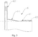
- FIG. 3 is a partial cross-sectional view of a flexible wheel of a speed reducer according to a second embodiment of the present application.
- an outer wheel tooth set 63 is disposed at a first end of the peripheral wall 61 of the flexible wheel 6 along the axial direction.
- a flange 62 is connected to a second end of the peripheral wall 61 along the axial direction.
- An inner diameter of the peripheral wall 61 gradually increases from a middle part of the peripheral wall 61 to the second end close to the flange 62, a total area of the peripheral wall 61 is increased, such that a deformability of the peripheral wall 61 is increased.
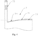
- FIG. 4 is a partial cross-sectional view of a flexible wheel of a third embodiment of a speed reducer according to the present application.
- an outer wheel tooth set 73 is disposed on a first end of the peripheral wall 71 of the flexible wheel 7 along the axial direction.
- a flange 72 is connected to a second end of the peripheral wall 71 along the axial direction.
- An inner diameter of the peripheral wall 71 gradually decreases from a middle part of the peripheral wall 71 to the second end close to the flange 72.
- the peripheral wall 71 with a gradually reduced inner diameter has a function of guiding and positioning, which further ensures a coaxiality of the connection between the flexible bearing and the peripheral wall 71, and further ensures a uniformity of the deformation of the peripheral wall 71.
Landscapes
- Engineering & Computer Science (AREA)
- General Engineering & Computer Science (AREA)
- Mechanical Engineering (AREA)
- Robotics (AREA)
- Retarders (AREA)
- General Details Of Gearings (AREA)
Abstract
Description
- The present application claims priority to Chinese Patent Application No.
201811092720.X, filed on September 19, 2018 - The present application relates to the technical field of deceleration device, in particular to a speed reducer and a robot applying the speed reducer.
- A harmonic gear reducer is a speed reducer composed of a rigid wheel, a flexible wheel and a harmonic generator that radially deforms the flexible wheel. Harmonic gear reducer has advantages of high precision, high carrying capacity, large transmission ratio, small size, light weight and the like, and the harmonic gear reducer is widely used in field of electronics industry, aerospace industry, robot industry, machine tool industry, other industries and the like. The harmonic generator of the harmonic gear reducer includes a flexible bearing and a cam. The cam is inserted into the flexible bearing, such that the flexible bearing deforms and has an oval outer surface. The flexible bearing is installed in a fitting position enclosed by a peripheral wall of the flexible wheel, so that the peripheral wall of the flexible wheel deforms according to a contour of the flexible bearing, and the outer wheel tooth set on an outer circumference of the flexible wheel is arranged in an oval shape.
- In order to meet a lightweight requirements, traditional harmonic gear reducers usually use flexible bearings with smaller sizes and shorter axial lengths, and following is a technical problem that an axial length of the flexible bearing is too short, such that the expansion and deformation of the peripheral wall along the axial direction will be incomplete, as a result, a meshing contact between the outer wheel tooth set and the inner wheel tooth set is insufficient, resulting in transmission errors; in addition, the axial length of a flexible bearing is too short, it is difficult to ensure an installation coaxiality between the flexible bearing having short axial length and the flexible wheel, the expansion and deformation of the peripheral wall along the radial direction are uneven, and a stress state of the flexible bearing is unstable, such that the transmission errors are generated and a service life of the flexible bearing is shortened.
- A first purpose of the present application is to provide a speed reducer with less transmission errors and longer service life.
- A second purpose of the present application is to provide a robot with less transmission errors and longer service life.
- The reducer provided by the first purpose of the present application includes a rigid wheel, a flexible wheel and a flexible bearing. The rigid wheel is provided with a first fitting position in a middle of the rigid wheel. An inner wheel tooth set is disposed on an inner side of the rigid wheel, and the inner wheel tooth set faces the first fitting position. The flexible wheel has a peripheral wall. The peripheral wall encloses a second fitting position. An outer peripheral surface is disposed on an outer side of the peripheral wall. An outer wheel tooth set is disposed on the outer peripheral surface of the peripheral wall. An inner peripheral surface is disposed on an inner side along a radial direction of the peripheral wall, and the inner peripheral surface faces the second fitting position. The flexible bearing is installed in the second fitting position and abuts against the inner peripheral surface. The flexible wheel is installed in the first fitting position. The outer wheel tooth set engages with the inner wheel tooth set. Along an axial direction of the rigid wheel, a length of a tooth top of the outer wheel tooth set is a first length, a length of a tooth root of the outer wheel tooth set is a second length, a tooth top of the inner wheel tooth set is a third length, and a length of the flexible bearing is a fourth length. Both the second length and the third length are greater than the first length, and the fourth length is greater than the second length.
- It can be seen from the above solution, since the fourth length of the flexible bearing is greater than the second length of the tooth root of the outer wheel tooth set, a part, on which the outer wheel tooth set is located, of the peripheral wall is fully expanded under contact with the flexible bearing. In addition, since the flexible bearing has a greater length, the installation coaxiality of the flexible bearing and the peripheral wall is guaranteed, such that the peripheral wall expand and deform uniformly along a peripheral direction, and a meshing and contact between the outer wheel tooth set and the inner wheel tooth set are more sufficient, thereby effectively reducing transmission errors and prolonging the service life of the flexible bearing.
- In one of the embodiments, the second length is greater than the third length.
- It can be seen that this solution can ensure that the meshing between the outer gear set and the inner gear set is sufficient.
- Further, along the axial direction of the rigid wheel, the peripheral wall has a fifth length. The fourth length is greater than 0.3 times the fifth length and less than 0.7 times the fifth length.
- In one of the embodiments, along the axial direction of the rigid wheel, the peripheral wall has a fifth length. The fourth length is greater than 0.5 times the fifth length and less than 0.6 times the fifth length.
- It can be seen that the greater a proportion of the fourth length of the flexible bearing along the axial direction relative to the fifth length of the peripheral wall is, the more uniform the deformation of the deformation of the peripheral wall caused by the flexible bearing and the flexible bearing itself will be.
- In one of the embodiments, the fourth length is greater than 0.2 times the diameter of the inner peripheral surface.
- In one of the embodiments, the fourth length is greater than 0.3 times the diameter of the inner peripheral surface.
- It can be seen that, in a case where the proportion of the fourth length of the flexible bearing along the axial direction relative to the diameter of the inner peripheral surface is increased, a possibility of the flexible bearing swinging relative to the peripheral wall is reduced, a maximum amount of swing that can be generated is decreased, the transmission is more stable and the transmission error is less.
- In one of the embodiments, along an axial direction of the flexible wheel, the outer wheel tooth set is disposed at a first end of the peripheral wall. The inner diameter of the peripheral wall gradually decreases from a middle part of the peripheral wall to a second end of the peripheral wall.
- In one of the embodiments, along an axial direction of the flexible wheel, the outer wheel tooth set is disposed at a first end of the peripheral wall. The inner diameter of the peripheral wall gradually increases from a middle part of the peripheral wall to a second end of the peripheral wall. Further, on a radial section of the rigid wheel, the inner peripheral surface is parallel to an axis of the rigid wheel.
- It can be seen that the inner peripheral surface having a cylindrical shape can improve a uniformity of the deformation of the peripheral wall.
- In one of the embodiments, along the radial direction of the rigid wheel, a first end surface of the flexible bearing is disposed on a first plane, and a second end surface of the flexible bearing is disposed on a second plane. The outer wheel tooth set is integrally located between the first plane and the second plane.
- It can be seen that the deformation of the peripheral wall caused by the flexible bearing can be completely reflected on the deformation of the outer wheel tooth set, so that the meshing between the outer wheel tooth set and the inner wheel tooth set is more sufficient.
- In one of the embodiments, the speed reducer further includes a harmonic generator. The harmonic generator includes a rotating drive part and a cam connected to an output end of the rotating drive part. The flexible bearing is sleeved on the cam.
- In one of the embodiments, along the axial direction of the flexible wheel, the outer wheel tooth set is disposed at a first end of the peripheral wall, and a flange is disposed at a second end of the peripheral wall.
- In one of the embodiments, the rigid wheel and the flexible wheel are connected by a rigid bearing.
- The robot provided by the second purpose of the present application includes a first part and a second part rotating relative to the first part. The robot further includes the speed reducer as described above. The speed reducer is connected between the first part and the second part.
- As can be seen from the above solution, there is a joint between the first part and the second part, and the robot adopts the speed reducer as described above at the joint to make the robot have the characteristics of stable work, accurate positioning, long service life and the like.
-
-
Fig. 1 is a cross-sectional view of a speed reducer according to a first embodiment of the present application. -
Fig. 2 is a partial cross-sectional view of the speed reducer according to the first embodiment of the present application. -
Fig. 3 is a partial cross-sectional view of a flexible wheel of a speed reducer according to a second embodiment of the present application. -
Fig. 4 is a partial cross-sectional view of a flexible wheel of a speed reducer according to a third embodiment of the present application. - The following further describes the present application with reference to the accompanying drawings and the embodiments.
- Refer to
Fig. 1 , which is a cross-sectional view of a speed reducer according to a first embodiment of the present application. The speed reducer provided in the present application is a harmonic reducer applied to a joint of a robot. The robot may be an industrial robot arm. The industrial robot arm has a first arm (a first part) and a second arm (a second part). There is a joint between the first arm and the second arm. The harmonic reducer is disposed at the joint. A relative rotation between the first arm and the second arm is realized by the harmonic reducer. - The harmonic reducer includes a flexible wheel 1, a
rigid wheel 2, a flexible bearing 3, a rigid bearing 5 and a harmonic generator. The flexible wheel 1 is in a cylindrical shape. The flexible wheel 1 has aperipheral wall 11 having a cylindrical shape. Theperipheral wall 11 encloses a secondfitting position 10, the secondfitting position 10 penetrates two ends of the flexible wheel 1 along the axial direction. An inner side of theperipheral wall 11 is an innerperipheral surface 111 facing the secondfitting position 10. On a radial section of therigid wheel 2, the innerperipheral surface 111 is parallel to an axis of therigid wheel 2. An outer side of theperipheral wall 11 is an outerperipheral surface 112 corresponding to the innerperipheral surface 111. Along the axial direction of the flexible wheel 1, an outer wheel tooth set 113 is disposed on a first end of the outerperipheral surface 112. A plurality of outer wheel teeth of the outer wheel tooth set 113 are arranged around an outer circumference of theperipheral wall 11. Along the axial direction of the flexible wheel 1, aflange 12 is connected to a second end of theperipheral wall 11. Theflange 12 surrounds theperipheral wall 11. Optionally, theperipheral wall 11 is provided with a plurality of through holes penetrating theperipheral wall 11. The plurality of through holes are uniformly arranged along a circumferential direction of theperipheral wall 11. - The
rigid wheel 2 has an annular shape. Therigid wheel 2 encloses a first fitting position. The first fitting position penetrates two ends of therigid wheel 2 along the axial direction of therigid wheel 2. An inner wheel tooth set 21 facing the first fitting position is disposed on the inner side of therigid wheel 2. - The flexible wheel 1 is rotatably connected to the
rigid wheel 2 by a rigid bearing 5. The rigid bearing 5 includes a rigidouter ring 51, a rigidinner ring 52 and rollers arranged between the rigidouter ring 51 and the rigidinner ring 52. The rigidouter ring 51 is fixedly connected to theflange 12 of the flexible wheel 1 by bolts. The rigidinner ring 52 is fixedly connected to therigid wheel 2 by bolts. - The harmonic generator includes a rotating drive part and a
cam 4. Thecam 4 is connected to an output end of the rotating drive part. The rotating drive part is a motor. Thecam 4 is connected to an output shaft of the motor through a self-aligning coupling. The flexible bearing 3 is sleeved on thecam 4. - The flexible bearing 3 includes a flexible
outer ring 31, a flexibleinner ring 32 and rollers arranged between the flexibleouter ring 31 and the flexibleinner ring 32. Since the flexible bearing 3 has an ability to deform, the flexible bearing 3 can deform according to an outer contour of thecam 4 after being sleeved on thecam 4. Therefore, the flexible bearing 3 has an oval outer contour after the flexible bearing 3 is sleeved on thecam 4. The flexible bearing 3 is disposed into the secondfitting position 10. The flexible bearing 3 is in transitional fit with theperipheral wall 11. The outer peripheral surface of the flexibleouter ring 31 abuts against the innerperipheral surface 111, such that theperipheral wall 11 is expanded and deformed. - Refer to
Fig. 2 , which is a partial cross-sectional view of the speed reducer according to the first embodiment of the present application. Along the axial direction of therigid wheel 2, atooth top 113a of the outer wheel tooth set 113 has a first length d1, atooth root 113b of the outer wheel tooth set 113 has a second length d2, a tooth top of the inner wheel tooth set 21 has a third length d3, the flexibleouter ring 31 has a fourth length d4, theperipheral wall 11 has a fifth length d5, and the innerperipheral surface 111 has a diameter d6. The second length d2 is greater than the third length d3. The second length d2 and the third length d3 are both greater than the first the length d1. The fourth length d4 is greater than the second length d2. In this embodiment, the fourth length d4 is greater than 0.3 times the diameter d6 of the innerperipheral surface 111. The fourth length d4 is greater than 0.5 times the fifth length d5 and less than 0.6 times the fifth length d5. - Along the axial direction of the
rigid wheel 2, the flexible bearing 3 has a first end surface L1 and a second end surface L2. As shown from the cross-sectional view along the radial direction of the speed reducer, the outer wheel tooth set 113 is integrally located in the space between the first plane where the first end surface L1 of the flexible bearing 3 is located and the second plane where the second end surface L2 of the flexible bearing 3 is located. With the existence of the flexible bearing 3, the part of theperipheral wall 11 where the outer wheel tooth set is located is fully expanded, and the installation coaxiality of the flexible bearing 3 and theperipheral wall 11 is guaranteed due to that the flexible bearing 3 has a greater length, such that theperipheral wall 11 expand and deform uniformly along the circumferential direction and the meshing and contact between the outer wheel tooth set 113 and the inner wheel tooth set 21 are more sufficient, thereby effectively reducing transmission errors and extending the service life of the flexible bearing. - In a case that the proportion of the fourth length d4 relative to the fifth length d5 and the proportion of the fourth length d4 relative to the diameter d6 of the inner
peripheral surface 111 are increased, the deformation of theperipheral wall 11 caused by the flexible bearing 3 and the deformation of the flexible bearing 3 itself are more uniform, the possibility of the flexible bearing 3 swinging relative to theperipheral wall 11 is reduced, the maximum amount of swing that can be generated is decreased, the transmission is more stable, and the transmission error is less. However, the proportion of the fourth length d4 relative to the fifth length d5 should not be too large, otherwise the installation difficulty of the flexible bearing 3 will increase. - Refer to
Fig. 3 , which is a partial cross-sectional view of a flexible wheel of a speed reducer according to a second embodiment of the present application. In this embodiment, an outer wheel tooth set 63 is disposed at a first end of theperipheral wall 61 of the flexible wheel 6 along the axial direction. Aflange 62 is connected to a second end of theperipheral wall 61 along the axial direction. An inner diameter of theperipheral wall 61 gradually increases from a middle part of theperipheral wall 61 to the second end close to theflange 62, a total area of theperipheral wall 61 is increased, such that a deformability of theperipheral wall 61 is increased. - Refer to
Fig. 4 , which is a partial cross-sectional view of a flexible wheel of a third embodiment of a speed reducer according to the present application. In this embodiment, an outer wheel tooth set 73 is disposed on a first end of theperipheral wall 71 of the flexible wheel 7 along the axial direction. Aflange 72 is connected to a second end of theperipheral wall 71 along the axial direction. An inner diameter of theperipheral wall 71 gradually decreases from a middle part of theperipheral wall 71 to the second end close to theflange 72. After the flexible bearing is installed, theperipheral wall 71 with a gradually reduced inner diameter has a function of guiding and positioning, which further ensures a coaxiality of the connection between the flexible bearing and theperipheral wall 71, and further ensures a uniformity of the deformation of theperipheral wall 71. - Finally, it should be emphasized that the foregoing descriptions are merely specific implementation manners of the present application, and are not intended to limit the protection scope of the present application. Any variation or replacement readily figured out by a person skilled in the art within the technical scope disclosed in the present application shall fall within the protection scope of the present application.
Claims (14)
- A speed reducer, comprising a rigid wheel, a flexible wheel and a flexible bearing;
wherein the rigid wheel is configured to enclose a first fitting position, and an inner wheel tooth set facing the first fitting position is disposed on an inner side of the rigid wheel along a radial direction of the rigid wheel;
the flexible wheel comprises a peripheral wall, the peripheral wall encloses a second fitting position, an outer wheel tooth set is disposed on an outer peripheral surface of the peripheral wall, and an inner peripheral surface facing the second fitting position is disposed on the inner side of the flexible wheel in a radial direction of the flexible wheel;
the flexible bearing is installed in the second fitting position and abuts against the inner peripheral surface of the peripheral wall, the flexible wheel is installed in the first fitting position, and the outer wheel tooth set is engaged with the inner wheel tooth set;
along an axial direction of the rigid wheel, a length of a tooth top of the outer wheel tooth set is a first length, a length of a tooth root of the outer wheel tooth set is a second length, a length of a tooth top of the inner wheel tooth set is a third length, and a length of the flexible bearing is a fourth length; and
both the second length and the third length are greater than the first length, and the fourth length is greater than the second length. - The speed reducer according to claim 1, wherein the second length is greater than the third length.
- The speed reducer according to claim 1, wherein along the axial direction of the rigid wheel, a length of the peripheral wall is a fifth length; and
the fourth length is greater than 0.3 times the fifth length and less than 0.7 times the fifth length. - The speed reducer according to claim 3, wherein the fourth length is greater than 0.5 times the fifth length and less than 0.6 times the fifth length.
- The speed reducer according to any one of claims 1 to 4, wherein the fourth length is greater than 0.2 times a diameter of the inner peripheral surface.
- The speed reducer according to claim 5, wherein the fourth length is greater than 0.3 times the diameter of the inner peripheral surface.
- The speed reducer according to any one of claims 1 to 4, wherein along an axial direction of the flexible wheel, the outer wheel tooth set is disposed at a first end of the peripheral wall, and an inner diameter of the peripheral wall gradually decreases from a middle part of the peripheral wall to a second end of the peripheral wall.
- The speed reducer according to any one of claims 1 to 4, wherein along an axial direction of the flexible wheel, the outer wheel tooth set is disposed at a first end of the peripheral wall, and an inner diameter of the peripheral wall gradually increases from a middle part of the peripheral wall to a second end of the peripheral wall.
- The speed reducer according to any one of claims 1 to 4, wherein on a radial section of the rigid wheel, the inner peripheral surface is parallel to an axis of the rigid wheel.
- The speed reducer according to any one of claims 1 to 4, wherein along the radial direction of the rigid wheel, a first end surface of the flexible bearing is located on a first plane, a second end surface of the flexible bearing is located on a second plane, and the outer wheel tooth set is located between the first plane and the second plane.
- The speed reducer according to any one of claims 1 to 4, wherein the speed reducer further comprises a harmonic generator, the harmonic generator comprises a rotating drive part and a cam connected to an output end of the rotating drive part; and
the flexible bearing is sleeved on the cam. - The speed reducer according to any one of claims 1 to 4, wherein along an axial direction of the flexible wheel, the outer wheel tooth set is disposed at a first end of the peripheral wall, and a flange is disposed at a second end of the peripheral wall.
- The speed reducer according to any one of claims 1 to 4, wherein the rigid wheel and the flexible wheel are connected by a rigid bearing.
- A robot, comprising a first part and a second part rotating relative to the first part, wherein the robot further comprises the speed reducer according to any one of claims 1 to 13, and the speed reducer is connected between the first part and the second part.
Applications Claiming Priority (2)
| Application Number | Priority Date | Filing Date | Title |
|---|---|---|---|
| CN201811092720.XA CN109027180B (en) | 2018-09-19 | 2018-09-19 | Speed reducer and robot |
| PCT/CN2018/122714 WO2020056963A1 (en) | 2018-09-19 | 2018-12-21 | Speed reducer and robot |
Publications (2)
| Publication Number | Publication Date |
|---|---|
| EP3839294A1 true EP3839294A1 (en) | 2021-06-23 |
| EP3839294A4 EP3839294A4 (en) | 2021-08-18 |
Family
ID=64617335
Family Applications (1)
| Application Number | Title | Priority Date | Filing Date |
|---|---|---|---|
| EP18934148.0A Withdrawn EP3839294A4 (en) | 2018-09-19 | 2018-12-21 | Speed reducer and robot |
Country Status (4)
| Country | Link |
|---|---|
| US (1) | US11648662B2 (en) |
| EP (1) | EP3839294A4 (en) |
| CN (1) | CN109027180B (en) |
| WO (1) | WO2020056963A1 (en) |
Cited By (1)
| Publication number | Priority date | Publication date | Assignee | Title |
|---|---|---|---|---|
| CN113969967A (en) * | 2021-10-26 | 2022-01-25 | 松山湖材料实验室 | Rigid wheel and preparation method thereof, harmonic reducer and application thereof |
Families Citing this family (9)
| Publication number | Priority date | Publication date | Assignee | Title |
|---|---|---|---|---|
| US11441660B2 (en) * | 2018-06-19 | 2022-09-13 | Harmonic Drive Systems Inc. | Hollow strain-wave gear device |
| CN109027180B (en) | 2018-09-19 | 2024-05-14 | 珠海格力电器股份有限公司 | Speed reducer and robot |
| CN110425266A (en) * | 2019-06-21 | 2019-11-08 | 珠海格力电器股份有限公司 | Cam structure, wave generator, harmonic reducer and cam machining process |
| JP7323164B2 (en) * | 2019-07-01 | 2023-08-08 | ニデックドライブテクノロジー株式会社 | Flexible external gear and strain wave gearing |
| CN112081895B (en) * | 2020-08-27 | 2025-08-29 | 珠海格力电器股份有限公司 | Camshafts, wave generators, harmonic reducers, robots |
| JP7725243B2 (en) * | 2021-05-31 | 2025-08-19 | ニデックドライブテクノロジー株式会社 | Flexible external gear, strain wave gear device, and robot device |
| CN115929852B (en) * | 2022-11-09 | 2025-09-12 | 珠海格力电器股份有限公司 | A reducer with high rigidity and long service life |
| CN116538265B (en) * | 2023-05-15 | 2024-05-10 | 睿尔曼智能科技(北京)有限公司 | A flexible wheel, a harmonic reducer, a mechanical arm and a robot |
| CN117028409A (en) * | 2023-08-08 | 2023-11-10 | 珠海格力电器股份有限公司 | A flexible bearing and harmonic reducer |
Family Cites Families (22)
| Publication number | Priority date | Publication date | Assignee | Title |
|---|---|---|---|---|
| SU894267A1 (en) * | 1980-03-04 | 1981-12-30 | Харьковский авиационный институт им.Н.Е.Жуковского | Wave toothed gearing |
| CN2351616Y (en) * | 1998-10-22 | 1999-12-01 | 中国科学院长春光学精密机械研究所 | Harmonic speed reducer |
| JP2003176857A (en) * | 2001-12-11 | 2003-06-27 | Teijin Seiki Co Ltd | Flex spline for meshing gear device and meshing gear device having the flex spline |
| US7891272B2 (en) * | 2006-11-14 | 2011-02-22 | Schonlau William J | Robotic harmonic flex-drive |
| CN103649586B (en) * | 2012-05-23 | 2016-11-02 | 谐波传动系统有限公司 | Wave gear device and flexible external tooth gear |
| CN102678881B (en) | 2012-05-31 | 2015-04-15 | 哈尔滨工业大学 | Rigid gear and flexible gear which are used for short-tube flexible-gear harmonic speed reducer and machining process thereof |
| CN202732859U (en) * | 2012-06-21 | 2013-02-13 | 苏州绿的谐波传动科技有限公司 | Harmonic reducer with flexibility felly |
| JP2015209931A (en) * | 2014-04-28 | 2015-11-24 | キヤノン株式会社 | Wave gear device and robot arm |
| CN105605197A (en) * | 2015-12-31 | 2016-05-25 | 北京工商大学 | Flexible gear with cylinder body having corrugated structure |
| CN106224487A (en) * | 2016-07-29 | 2016-12-14 | 柳州福能机器人开发有限公司 | Robot high-accuracy decelerator drive mechanism |
| CN206072245U (en) | 2016-08-31 | 2017-04-05 | 惠州比亚迪实业有限公司 | For the firm wheel of harmonic speed reducer, harmonic speed reducer and robot |
| DE102016218927A1 (en) * | 2016-09-29 | 2017-11-02 | Schaeffler Technologies AG & Co. KG | The wave gear |
| DE102016220916A1 (en) * | 2016-10-25 | 2017-10-12 | Schaeffler Technologies AG & Co. KG | Ring gear for a wave gear, wave gear with the ring gear, shaft adjustment with the wave gear and method for manufacturing the ring gear |
| CN206246608U (en) * | 2016-12-03 | 2017-06-13 | 广东宝控智能装备科技有限公司 | Mechatronic Harmonic Reducer |
| TWI641771B (en) * | 2016-12-29 | 2018-11-21 | 財團法人工業技術研究院 | Harmonic driving device |
| KR102379849B1 (en) * | 2017-02-28 | 2022-03-28 | 하모닉 드라이드 아게 | Strain wave gear mechanism with inner seal |
| CN207122561U (en) * | 2017-09-08 | 2018-03-20 | 珠海飞马传动机械有限公司 | A kind of low-noise compact type harmonic wave speed reducing machine |
| CN107893840A (en) | 2017-10-20 | 2018-04-10 | 崔鹏 | A kind of more wave number harmonic speed reducers |
| CN207715678U (en) * | 2017-12-22 | 2018-08-10 | 众合天成智能装备(廊坊)有限公司 | A kind of harmonic speed reducer suitable for printing machinery |
| DE102019105760A1 (en) * | 2018-03-08 | 2019-09-12 | Schaeffler Technologies AG & Co. KG | Corrugated transmission and method for producing an elastic transmission component |
| CN208778633U (en) * | 2018-09-19 | 2019-04-23 | 珠海格力电器股份有限公司 | Reduction gear and robot |
| CN109027180B (en) * | 2018-09-19 | 2024-05-14 | 珠海格力电器股份有限公司 | Speed reducer and robot |
-
2018
- 2018-09-19 CN CN201811092720.XA patent/CN109027180B/en active Active
- 2018-12-21 WO PCT/CN2018/122714 patent/WO2020056963A1/en not_active Ceased
- 2018-12-21 EP EP18934148.0A patent/EP3839294A4/en not_active Withdrawn
-
2021
- 2021-03-11 US US17/198,507 patent/US11648662B2/en active Active
Cited By (2)
| Publication number | Priority date | Publication date | Assignee | Title |
|---|---|---|---|---|
| CN113969967A (en) * | 2021-10-26 | 2022-01-25 | 松山湖材料实验室 | Rigid wheel and preparation method thereof, harmonic reducer and application thereof |
| CN113969967B (en) * | 2021-10-26 | 2023-11-10 | 松山湖材料实验室 | Rigid wheel, preparation method thereof, harmonic reducer and application thereof |
Also Published As
| Publication number | Publication date |
|---|---|
| WO2020056963A1 (en) | 2020-03-26 |
| US11648662B2 (en) | 2023-05-16 |
| CN109027180B (en) | 2024-05-14 |
| EP3839294A4 (en) | 2021-08-18 |
| US20210197365A1 (en) | 2021-07-01 |
| CN109027180A (en) | 2018-12-18 |
Similar Documents
| Publication | Publication Date | Title |
|---|---|---|
| US11648662B2 (en) | Speed reducer and robot | |
| CN108843746B (en) | Precise speed reducer for robot | |
| US9709151B2 (en) | Wave generator and strain wave gearing | |
| KR200450505Y1 (en) | reducer | |
| CN111791261A (en) | A joint module of a collaborative robot | |
| CN108036034A (en) | A kind of bidirectional output type harmonic speed changer | |
| EP2397721B1 (en) | Sun-and-planet speed-up gear | |
| EP2672146A1 (en) | Harmonic drive with stationary flexspine | |
| CN111963647B (en) | Harmonic speed reducer and automation equipment | |
| CN211259531U (en) | Novel structure harmonic speed reducer ware | |
| EP2674642A1 (en) | Harmonic drive with stationary gear | |
| CN208778633U (en) | Reduction gear and robot | |
| CN114934991B (en) | Wave generator components, harmonic reducers and robots | |
| CN208057893U (en) | A kind of self-positioning harmonic speed reducer structure | |
| CN104791456B (en) | Automatic adjusting gap wave generator for harmonic reducer | |
| CN117458769B (en) | A motor and integrated joint with integrated wave generator | |
| CN119802166A (en) | RV reducer and industrial robot | |
| CN211951366U (en) | Flexible wheel and harmonic reducer | |
| JP2023163831A (en) | Wave gearing and industrial robots | |
| TW201710610A (en) | Power transmission apparatus with inscribed cam and cylindrical pinions capable of efficiently transmitting motor rotation and being precisely positioned | |
| CN211423284U (en) | Cycloidal speed reducer | |
| CN106838266B (en) | Bearing reducer cage | |
| CN110799772B (en) | Drive device | |
| CN114233815B (en) | RV speed reduction device and robot | |
| CN221482601U (en) | Harmonic reducer and robot |
Legal Events
| Date | Code | Title | Description |
|---|---|---|---|
| STAA | Information on the status of an ep patent application or granted ep patent |
Free format text: STATUS: THE INTERNATIONAL PUBLICATION HAS BEEN MADE |
|
| PUAI | Public reference made under article 153(3) epc to a published international application that has entered the european phase |
Free format text: ORIGINAL CODE: 0009012 |
|
| STAA | Information on the status of an ep patent application or granted ep patent |
Free format text: STATUS: REQUEST FOR EXAMINATION WAS MADE |
|
| 17P | Request for examination filed |
Effective date: 20210315 |
|
| AK | Designated contracting states |
Kind code of ref document: A1 Designated state(s): AL AT BE BG CH CY CZ DE DK EE ES FI FR GB GR HR HU IE IS IT LI LT LU LV MC MK MT NL NO PL PT RO RS SE SI SK SM TR |
|
| A4 | Supplementary search report drawn up and despatched |
Effective date: 20210715 |
|
| RIC1 | Information provided on ipc code assigned before grant |
Ipc: F16H 49/00 20060101AFI20210709BHEP |
|
| DAV | Request for validation of the european patent (deleted) | ||
| DAX | Request for extension of the european patent (deleted) | ||
| STAA | Information on the status of an ep patent application or granted ep patent |
Free format text: STATUS: EXAMINATION IS IN PROGRESS |
|
| 17Q | First examination report despatched |
Effective date: 20220328 |
|
| STAA | Information on the status of an ep patent application or granted ep patent |
Free format text: STATUS: THE APPLICATION HAS BEEN WITHDRAWN |
|
| 18W | Application withdrawn |
Effective date: 20220728 |