EP3839214A1 - Component having a dirt tolerant passage turn - Google Patents
Component having a dirt tolerant passage turn Download PDFInfo
- Publication number
- EP3839214A1 EP3839214A1 EP20212941.7A EP20212941A EP3839214A1 EP 3839214 A1 EP3839214 A1 EP 3839214A1 EP 20212941 A EP20212941 A EP 20212941A EP 3839214 A1 EP3839214 A1 EP 3839214A1
- Authority
- EP
- European Patent Office
- Prior art keywords
- passage
- projection
- component
- extending
- turn
- Prior art date
- Legal status (The legal status is an assumption and is not a legal conclusion. Google has not performed a legal analysis and makes no representation as to the accuracy of the status listed.)
- Granted
Links
Images




Classifications
-
- F—MECHANICAL ENGINEERING; LIGHTING; HEATING; WEAPONS; BLASTING
- F01—MACHINES OR ENGINES IN GENERAL; ENGINE PLANTS IN GENERAL; STEAM ENGINES
- F01D—NON-POSITIVE DISPLACEMENT MACHINES OR ENGINES, e.g. STEAM TURBINES
- F01D25/00—Component parts, details, or accessories, not provided for in, or of interest apart from, other groups
- F01D25/32—Collecting of condensation water; Drainage ; Removing solid particles
-
- F—MECHANICAL ENGINEERING; LIGHTING; HEATING; WEAPONS; BLASTING
- F01—MACHINES OR ENGINES IN GENERAL; ENGINE PLANTS IN GENERAL; STEAM ENGINES
- F01D—NON-POSITIVE DISPLACEMENT MACHINES OR ENGINES, e.g. STEAM TURBINES
- F01D5/00—Blades; Blade-carrying members; Heating, heat-insulating, cooling or antivibration means on the blades or the members
- F01D5/12—Blades
- F01D5/14—Form or construction
- F01D5/18—Hollow blades, i.e. blades with cooling or heating channels or cavities; Heating, heat-insulating or cooling means on blades
- F01D5/187—Convection cooling
-
- F—MECHANICAL ENGINEERING; LIGHTING; HEATING; WEAPONS; BLASTING
- F01—MACHINES OR ENGINES IN GENERAL; ENGINE PLANTS IN GENERAL; STEAM ENGINES
- F01D—NON-POSITIVE DISPLACEMENT MACHINES OR ENGINES, e.g. STEAM TURBINES
- F01D5/00—Blades; Blade-carrying members; Heating, heat-insulating, cooling or antivibration means on the blades or the members
- F01D5/12—Blades
- F01D5/14—Form or construction
- F01D5/18—Hollow blades, i.e. blades with cooling or heating channels or cavities; Heating, heat-insulating or cooling means on blades
- F01D5/187—Convection cooling
- F01D5/188—Convection cooling with an insert in the blade cavity to guide the cooling fluid, e.g. forming a separation wall
-
- F—MECHANICAL ENGINEERING; LIGHTING; HEATING; WEAPONS; BLASTING
- F01—MACHINES OR ENGINES IN GENERAL; ENGINE PLANTS IN GENERAL; STEAM ENGINES
- F01D—NON-POSITIVE DISPLACEMENT MACHINES OR ENGINES, e.g. STEAM TURBINES
- F01D9/00—Stators
- F01D9/02—Nozzles; Nozzle boxes; Stator blades; Guide conduits, e.g. individual nozzles
- F01D9/04—Nozzles; Nozzle boxes; Stator blades; Guide conduits, e.g. individual nozzles forming ring or sector
- F01D9/041—Nozzles; Nozzle boxes; Stator blades; Guide conduits, e.g. individual nozzles forming ring or sector using blades
-
- F—MECHANICAL ENGINEERING; LIGHTING; HEATING; WEAPONS; BLASTING
- F01—MACHINES OR ENGINES IN GENERAL; ENGINE PLANTS IN GENERAL; STEAM ENGINES
- F01D—NON-POSITIVE DISPLACEMENT MACHINES OR ENGINES, e.g. STEAM TURBINES
- F01D5/00—Blades; Blade-carrying members; Heating, heat-insulating, cooling or antivibration means on the blades or the members
- F01D5/12—Blades
- F01D5/14—Form or construction
- F01D5/18—Hollow blades, i.e. blades with cooling or heating channels or cavities; Heating, heat-insulating or cooling means on blades
- F01D5/186—Film cooling
-
- F—MECHANICAL ENGINEERING; LIGHTING; HEATING; WEAPONS; BLASTING
- F01—MACHINES OR ENGINES IN GENERAL; ENGINE PLANTS IN GENERAL; STEAM ENGINES
- F01D—NON-POSITIVE DISPLACEMENT MACHINES OR ENGINES, e.g. STEAM TURBINES
- F01D9/00—Stators
- F01D9/06—Fluid supply conduits to nozzles or the like
- F01D9/065—Fluid supply or removal conduits traversing the working fluid flow, e.g. for lubrication-, cooling-, or sealing fluids
-
- F—MECHANICAL ENGINEERING; LIGHTING; HEATING; WEAPONS; BLASTING
- F05—INDEXING SCHEMES RELATING TO ENGINES OR PUMPS IN VARIOUS SUBCLASSES OF CLASSES F01-F04
- F05D—INDEXING SCHEME FOR ASPECTS RELATING TO NON-POSITIVE-DISPLACEMENT MACHINES OR ENGINES, GAS-TURBINES OR JET-PROPULSION PLANTS
- F05D2240/00—Components
- F05D2240/10—Stators
- F05D2240/12—Fluid guiding means, e.g. vanes
-
- F—MECHANICAL ENGINEERING; LIGHTING; HEATING; WEAPONS; BLASTING
- F05—INDEXING SCHEMES RELATING TO ENGINES OR PUMPS IN VARIOUS SUBCLASSES OF CLASSES F01-F04
- F05D—INDEXING SCHEME FOR ASPECTS RELATING TO NON-POSITIVE-DISPLACEMENT MACHINES OR ENGINES, GAS-TURBINES OR JET-PROPULSION PLANTS
- F05D2240/00—Components
- F05D2240/10—Stators
- F05D2240/12—Fluid guiding means, e.g. vanes
- F05D2240/126—Baffles or ribs
-
- F—MECHANICAL ENGINEERING; LIGHTING; HEATING; WEAPONS; BLASTING
- F05—INDEXING SCHEMES RELATING TO ENGINES OR PUMPS IN VARIOUS SUBCLASSES OF CLASSES F01-F04
- F05D—INDEXING SCHEME FOR ASPECTS RELATING TO NON-POSITIVE-DISPLACEMENT MACHINES OR ENGINES, GAS-TURBINES OR JET-PROPULSION PLANTS
- F05D2250/00—Geometry
- F05D2250/10—Two-dimensional
- F05D2250/18—Two-dimensional patterned
- F05D2250/185—Two-dimensional patterned serpentine-like
-
- F—MECHANICAL ENGINEERING; LIGHTING; HEATING; WEAPONS; BLASTING
- F05—INDEXING SCHEMES RELATING TO ENGINES OR PUMPS IN VARIOUS SUBCLASSES OF CLASSES F01-F04
- F05D—INDEXING SCHEME FOR ASPECTS RELATING TO NON-POSITIVE-DISPLACEMENT MACHINES OR ENGINES, GAS-TURBINES OR JET-PROPULSION PLANTS
- F05D2260/00—Function
- F05D2260/20—Heat transfer, e.g. cooling
- F05D2260/221—Improvement of heat transfer
- F05D2260/2214—Improvement of heat transfer by increasing the heat transfer surface
- F05D2260/22141—Improvement of heat transfer by increasing the heat transfer surface using fins or ribs
-
- F—MECHANICAL ENGINEERING; LIGHTING; HEATING; WEAPONS; BLASTING
- F05—INDEXING SCHEMES RELATING TO ENGINES OR PUMPS IN VARIOUS SUBCLASSES OF CLASSES F01-F04
- F05D—INDEXING SCHEME FOR ASPECTS RELATING TO NON-POSITIVE-DISPLACEMENT MACHINES OR ENGINES, GAS-TURBINES OR JET-PROPULSION PLANTS
- F05D2260/00—Function
- F05D2260/60—Fluid transfer
- F05D2260/607—Preventing clogging or obstruction of flow paths by dirt, dust, or foreign particles
Definitions
- This disclosure relates generally to components for gas turbine engines, and more particularly to purging debris particles from said components.
- Components for gas turbine engines may typically include complex internal cooling passages receiving a cooling fluid from a cooling source.
- the cooling fluid transiting the cooling passages may include dirt, debris, or other particulate entrained therein.
- debris particles may impact the walls of the internal cooling passages and potentially become deposited on the walls. Over time, accumulation of debris particles on the walls of the cooling passages may result in degradation of component performance. Accordingly, what is needed is systems and/or methods addressing one or more of the above-noted concerns.
- a component includes a component body.
- the component further includes a first passage disposed in the component body.
- the first passage includes a first end and a second end opposite the first end.
- the component further includes a second passage.
- the second passage extends from the second end of the first passage.
- the second passage includes a turn.
- the component further includes a third passage.
- the third passage extends from the second end of the first passage.
- the component further includes a first projection extending from a passage surface of the component body within the first passage. The first projection is disposed between the first and the second end of the first passage and is configured to direct debris transiting the first passage away from the second passage and into the third passage.
- the turn includes a radius, and a height of the first projection from the passage surface is between 10 percent of the radius and 50 percent of a diameter of the first passage.
- the height of the first projection is between 15 and 25 percent of the radius.
- the first passage further includes a first side and a second side opposite the first side.
- the first side and the second side extend between the first end and the second end of the first passage.
- the second passage extends from the first passage on the first side and the third passage extends from the first passage on the second side.
- the first projection extends from the passage surface on the first side of the first passage.
- the component further includes a second projection extending from the component body at the second end of the first passage.
- the second projection extends in a first direction from the second end of the first passage to the first end of the first passage and is disposed between the second passage and the third passage.
- a distance between the first projection and the second projection in the first direction from the second end of the first passage to the first end of the first passage is greater than or equal to 10 percent of the radius.
- the third passage includes a dirt purge outlet extending between the third passage and an exterior of the component.
- the dirt purge outlet extends in a second direction and the third passage extends in a third direction, different than the second direction.
- the component is an airfoil.
- the radius of the turn is an average radius along the extent of the turn.
- a distal end of the second projection is disposed upstream of the turn with respect to the first direction.
- the component body includes at least one heat augmentation feature disposed within the first passage.
- a method for purging dirt from a component includes providing a component body including a first passage disposed in the component body.
- the first passage includes a first end and a second end opposite the first end.
- the component body further includes a second passage extending from the second end of the first passage and a third passage extending from the second end of the first passage.
- the second passage includes a turn.
- the method further includes directing debris transiting the first passage away from the second passage and into the third passage with a first projection extending from a passage surface of the component body within the first passage.
- the first projection is disposed between the first end and the second end of the first passage.
- the turn includes a radius, and a height of the first projection from the passage surface is between 10 percent of the radius and 50 percent of a diameter of the first passage.
- the height of the first projection is between 15 and 25 percent of the radius.
- the component body further includes a second projection extending from the component body at the second end of the first passage.
- the second projection extends in a first direction from the second end of the first passage to the first end of the first passage and is disposed between the second passage and the third passage.
- the third passage includes a dirt purge outlet extending between the third passage and an exterior of the component.
- the dirt purge outlet extends in a second direction and the third passage extends in a third direction, different than the second direction.
- a distance between the first projection and the second projection in the first direction from the second end of the first passage to the first end of the first passage is greater than or equal to 10 percent of the radius.
- the radius of the turn is an average radius along the extent of the turn.
- a component for a gas turbine engine includes a component body.
- the component further includes a first passage disposed in the component body.
- the first passage includes a first end and a second end opposite the first end.
- the component further includes a second passage extending from the second end of the first passage.
- the second passage includes a turn.
- the component further includes a third passage extending from the second end of the first passage.
- the component further includes a first projection extending from a passage surface of the component body within the first passage. The first projection is disposed between the first end and the second end of the first passage and is configured to direct debris transiting the first passage away from the second passage and into the third passage.
- the turn includes a radius, and a height of first projection from the passage surface is between 10 percent of the radius and 50 percent of a diameter of the first passage.
- the component further includes a second projection extending from the component body at the second end of the first passage. The second projection disposed between the second passage and the third passage.
- the gas turbine engine 10 is schematically illustrated.
- the gas turbine engine 10 is disclosed herein as a two-spool turbofan engine that generally includes a fan section 12, a compressor section 14, a combustor section 16, and a turbine section 18.
- the fan section 12 drives air along a bypass flowpath 20 while the compressor section 14 drives air along a core flowpath 22 for compression and communication into the combustor section 16 and then expansion through the turbine section 18.
- a turbofan gas turbine engine in the disclosed non-limiting embodiments, it should be understood that the concepts described herein are not limited to use with turbofans as the teachings may be applied to other types of turbine engines including those with three-spool architectures.
- the gas turbine engine 10 generally includes a low-pressure spool 24 and a high-pressure spool 26 mounted for rotation about a longitudinal centerline 28 of the gas turbine engine 10 relative to an engine static structure 30 via one or more bearing systems 32. It should be understood that various bearing systems 32 at various locations may alternatively or additionally be provided.
- the low-pressure spool 24 generally includes a first shaft 34 that interconnects a fan 36, a low-pressure compressor 38, and a low-pressure turbine 40.
- the first shaft 34 is connected to the fan 36 through a gear assembly of a fan drive gear system 42 to drive the fan 36 at a lower speed than the low-pressure spool 24.
- the high-pressure spool 26 generally includes a second shaft 44 that interconnects a high-pressure compressor 46 and a high-pressure turbine 48. It is to be understood that "low pressure” and "high pressure” or variations thereof as used herein are relative terms indicating that the high pressure is greater than the low pressure.
- An annular combustor 50 is disposed between the high-pressure compressor 46 and the high-pressure turbine 48 along the longitudinal centerline 28.
- the first shaft 34 and the second shaft 44 are concentric and rotate via the one or more bearing systems 32 about the longitudinal centerline 28 which is collinear with respective longitudinal centerlines of the first and second shafts 34, 44.
- Airflow along the core flowpath 22 is compressed by the low-pressure compressor 38, then the high-pressure compressor 46, mixed and burned with fuel in the combustor 50, and then expanded over the high-pressure turbine 48 and the low-pressure turbine 40.
- the low-pressure turbine 40 and the high-pressure turbine 48 rotationally drive the low-pressure spool 24 and the high-pressure spool 26, respectively, in response to the expansion.
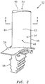
- FIG. 2 illustrates a blade 52 including an exemplary airfoil 54 which may form a portion of one or more of the blades 52 or vanes of the gas turbine engine 10.
- the blade 52 includes a platform 56 supported by a root 58 which may be secured to, for example, a rotor.
- the airfoil 54 extends radially from the platform 56, opposite the root 58, to a tip 60.
- the airfoil 54 includes an exterior surface 62 extending between a leading edge 64 and a trailing edge 66 and defining a pressure side 68 and opposite suction side 70 of the airfoil 54. While the airfoil 54 is illustrated as being part of a blade 52, it should be understood that the disclosed airfoil 54 can also be used as a vane.
- the airfoil 54 includes an airfoil body 72 defining a perimeter wall 74 of the airfoil 54.
- the airfoil body 72 may further define one or more ribs 76 extending between and connecting opposing portions of the perimeter wall 74.
- the perimeter wall 74 and ribs 76 of the airfoil body 72 may define one or more passages 78 (e.g., cooling air or fluid passages) disposed in the airfoil body 72.
- the airfoil body 72 may include film cooling holes or other apertures extending through the airfoil body 72 between the passages 78 and an exterior of the airfoil 54.
- the one or more passages 78 disposed in the airfoil body 72 may include, a series of interconnected passages, for example, a first passage 80, a second passage 82, and a third passage 84 defined by a passage surface 112 of the airfoil body 72.
- the first passage 80 includes a first end 86 and a second end 88 opposite the first end 86.
- the first passage 80 further includes a first side 90 and a second side 92 opposite the first side. The first side 90 and the second side 92 extend between the first end 86 and the second end 88 of the first passage 80.
- the second passage 82 extends from the second end 88 of the first passage 80 on the first side 90 while the third passage 84 extends from the second end 88 of the first passage 80 on the second side 92.
- the third passage 84 may be a tip flag cavity of the airfoil 54.
- cooling air flow 94 transiting the first passage 80 may flow generally in a direction from the first end 86 to the second end 88 of the first passage 80 and subsequently into the second and third passages 82, 84.
- the cooling air flow 94 may include dirt, debris, and other particulate material entrained therein.
- the first passage 80 may extend along a first passage center axis 96 extending generally in a direction between the first end 86 and the second end 88 of the first passage 80.
- the first passage center axis 96 may be substantially radially oriented relative to the longitudinal centerline 28 of the gas turbine engine 10.
- the second and third passages 82, 84 may include respective second and third passage center axes 98, 100 along which they extend.
- the second passage center axis 98 may be substantially parallel to the first passage center axis 96.
- the third passage center axis 100 may be substantially perpendicular to the first passage center axis 96.
- passages 80, 82, 84 may be oriented in any suitable direction relative to one another and are not limited to the exemplary description of the passage center axes 96, 98, 100 discussed above.
- airfoils may typically be curved, therefore, the passages therein may also be curved consistent with the shape of the airfoil.
- the diameter of the passages 80, 82, 84 may vary along the length of the passages 80, 82, 84.
- the term "substantially,” used in connection with an angular reference should be understood to mean a range of angles within five degrees of the stated angular orientation.
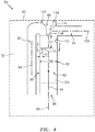
- the second passage 82 may include a turn 102 such as, for example, a serpentine turn as shown in FIG. 4 .
- the turn 102 may be located at an interface between the first passage 80 and the second passage 82 (e.g., at the second end 88 of the first passage 80).
- the turn 102 includes a radius which may be, for example, an average radius along the extent of the turn 102. While the present disclosure will be explained with respect to the airfoil 54, it should be understood that the concepts described herein may be applied to any component having fluid passages including a turn, for example, a component for a gas turbine engine having two passages connected by a turn (e.g., a blade outer air seal, an air-cooled combustor assembly component, etc.).
- the airfoil 54 includes a first projection 110 extending from the passage surface 112 of the airfoil body 72 within the first passage 80 and configured to direct debris transiting the first passage 80 away from the second passage 82 and into the third passage 84.
- the first projection 110 has a height H1 extending from the passage surface 112 into the first passage 80.
- the first projection 110 may extend from the passage surface 112 on a side 90, 92 of the first passage 80 which corresponds to the location of the turn 102. For example, as shown in FIG. 4 , the turn 102 of the second passage 82 and the first projection 110 are disposed on the first side 90 of the first passage 80. As shown in FIG.
- the first projection 110 may, for example, extend between and connect opposing portions of the perimeter wall 74 of the airfoil body 72, however, the first projection 110 may have any suitable orientation with respect to portions of the airfoil body 72. Further, the first projection 110 may have various shapes and should not be understood as being limited to the exemplary shape depicted in FIGS. 4 , 6 , and 7 . For example, the first projection 110 may be shaped as a ramp (e.g., having a height from the passages surface 112 which gradually increases in a direction from the first end 86 to the second end 88 of the first passage 80) or any other suitable shape for guiding the cooling air flow 94 in the desired direction.
- a ramp e.g., having a height from the passages surface 112 which gradually increases in a direction from the first end 86 to the second end 88 of the first passage 80
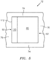
- the first projection 110 may extend only a portion of a distance across the first passage 80. While the first passage 80 of FIG. 5 is shown as having a generally square cross-sectional shape, it should be understood that the first passage 80 or other passages of the one or more passages 78 can have any suitable cross-sectional shape.
- the airfoil 54 may include a second projection 114 extending from the airfoil body 72 at the second end 88 of the first passage 80.
- the second projection 114 may be configured to guide debris directed away from the second passage 82, by the first projection 110, into the third passage 84.
- the second projection 114 may generally extend in a direction from the second end 88 of the first passage 80 toward the first end 86 of the first passage 80.
- the second projection 114 may be disposed between the second passage 82 and the third passage 84 and may define a portion of the turn 102 of the second passage 82.
- the first projection 110 and the second projection 114 may be separated by a distance D1 with respect to the first passage center axis 96.
- a distal end 118 of the second projection 114 may be disposed at or upstream of the turn 102 of the second passage 82 with respect to the first passage center axis 96 and the direction of the cooling air flow 94.
- the third passage 84 may include a dirt purge outlet 116 extending through the airfoil body 72 between the third passage 84 and an exterior of the airfoil 54. Debris directed by the first and second projections 110, 114 into the third passage 84 may pass out of the airfoil 54 through the dirt purge outlet 116.
- the dirt purge outlet 116 may extend in a direction different than the third passage center axis 100 of the third passage 84.
- the dirt purge outlet 116 may extend in a direction substantially parallel to the first passage center axis 96.
- Debris impacting the passage surface 112 at turns can result in significant debris accumulation along the passage surface 112 potentially resulting in accelerated distress of the airfoil 54 and undesirable corrective maintenance.
- One factor affecting the degree of debris accumulation is debris particle size. Debris enters the cooling passages 78 of the airfoil 54 with a distribution of sizes and the larger debris particles may be less likely to follow the flow field of the cooling air flow 94 for the entire transit of the turn 102. These larger debris particles may strike the passage surface 112 potentially resulting in deposition along the passage surface 112.
- the propensity for a debris particle to follow or deviate from the direction of the cooling air flow 94 may be estimated by the debris particle's Stokes number (St).
- ⁇ p represents a density of debris particle
- d represents a diameter of the debris particle
- U represents a velocity of the debris particle
- ⁇ g represents a viscosity of the fluid
- l 0 represents a length scale (e.g., the radius of the turn 102 or the height HI).
- the height H1 of the first projection 110 may be between 10 and 50 percent of the radius of the turn 102. In various embodiments, the height H1 of the first projection 110 may be between 15 and 25 percent of the radius of the turn 102. In various embodiments, the height H1 of the first projection 110 may be 20 percent of the radius of the turn 102. In various embodiments, the height H1 of the first projection 110 may be less than or equal to 50 percent of a distance D2 between the first side 90 and the second side 92 of the first passage 80 (e.g., a diameter of the first passage 80 at the location of the first projection 110). As used herein, a range of heights or other distances are inclusive of the endpoints of the range.
- the height H1 of the first projection 110 may be selected such that high-risk debris particles (e.g., relatively large debris particles) having a St value > 1, with respect to the first projection 110, may interact with the first projection 110 and be directed away from the turn 102. Additionally, in various embodiments, the distance D1 between the first projection 110 and the second projection 114 may be greater than or equal to 10 percent of the radius of the turn 102 (e.g., between 10 percent of the radius of the turn 102 and an entire length of the first passage 80). In various embodiments, the distance D1 between the first projection 110 and the second projection 114 may be between 40 and 200 percent of the radius of the turn 102, for example, to allow the second projection 114 to further guide the debris particles into the third passage 84. Selection of the height H1 of the first projection 110 may be selected such that the height H1 is sufficient to direct high-risk debris particles away from the turn 102 while minimizing a pressure drop of the cooling air flow 94 through the passages 78.
- high-risk debris particles e.g
- a debris particle with St ⁇ 1 may travel along a first particle flowpath 120 into the second passage 82 (see FIG. 6 ) while a debris particle with St > 1, with respect to the turn 102, may travel along a second particle flowpath 122 into the third passage 84 (see FIG. 7 ).
- the debris particle traveling along the second particle flowpath 122 may proceed through the third passage 84 or, alternatively, may be ejected from the airfoil 54 via the dirt purge outlet 116.
- the airfoil 54 may include one or more heat augmentation features 124 (e.g., trip strips, pedestals, etc.), distinct from the first and second projections 110, 114 to improve heat transfer or fluid flow within the passages 78 of the airfoil body 72.
- heat augmentation features 124 e.g., trip strips, pedestals, etc.
Landscapes
- Engineering & Computer Science (AREA)
- Mechanical Engineering (AREA)
- General Engineering & Computer Science (AREA)
- Turbine Rotor Nozzle Sealing (AREA)
Abstract
Description
- This disclosure relates generally to components for gas turbine engines, and more particularly to purging debris particles from said components.
- Components for gas turbine engines (e.g., airfoils) may typically include complex internal cooling passages receiving a cooling fluid from a cooling source. The cooling fluid transiting the cooling passages may include dirt, debris, or other particulate entrained therein. In some cases, debris particles may impact the walls of the internal cooling passages and potentially become deposited on the walls. Over time, accumulation of debris particles on the walls of the cooling passages may result in degradation of component performance. Accordingly, what is needed is systems and/or methods addressing one or more of the above-noted concerns.
- It should be understood that any or all of the features or embodiments described herein can be used or combined in any combination with each and every other feature or embodiment described herein unless expressly noted otherwise.
- According to an aspect of the present invention a component includes a component body. The component further includes a first passage disposed in the component body. The first passage includes a first end and a second end opposite the first end. The component further includes a second passage. The second passage extends from the second end of the first passage. The second passage includes a turn. The component further includes a third passage. The third passage extends from the second end of the first passage. The component further includes a first projection extending from a passage surface of the component body within the first passage. The first projection is disposed between the first and the second end of the first passage and is configured to direct debris transiting the first passage away from the second passage and into the third passage.
- Optionally, the turn includes a radius, and a height of the first projection from the passage surface is between 10 percent of the radius and 50 percent of a diameter of the first passage.
- Optionally, the height of the first projection is between 15 and 25 percent of the radius.
- Optionally, the first passage further includes a first side and a second side opposite the first side. The first side and the second side extend between the first end and the second end of the first passage. The second passage extends from the first passage on the first side and the third passage extends from the first passage on the second side.
- Optionally, the first projection extends from the passage surface on the first side of the first passage.
- Optionally, the component further includes a second projection extending from the component body at the second end of the first passage. The second projection extends in a first direction from the second end of the first passage to the first end of the first passage and is disposed between the second passage and the third passage.
- Optionally, a distance between the first projection and the second projection in the first direction from the second end of the first passage to the first end of the first passage is greater than or equal to 10 percent of the radius.
- Optionally, the third passage includes a dirt purge outlet extending between the third passage and an exterior of the component. The dirt purge outlet extends in a second direction and the third passage extends in a third direction, different than the second direction.
- Optionally, the component is an airfoil.
- Optionally, the radius of the turn is an average radius along the extent of the turn.
- Optionally, a distal end of the second projection is disposed upstream of the turn with respect to the first direction.
- Optionally, the component body includes at least one heat augmentation feature disposed within the first passage.
- According to another aspect of the present invention, a method for purging dirt from a component includes providing a component body including a first passage disposed in the component body. The first passage includes a first end and a second end opposite the first end. The component body further includes a second passage extending from the second end of the first passage and a third passage extending from the second end of the first passage. The second passage includes a turn. The method further includes directing debris transiting the first passage away from the second passage and into the third passage with a first projection extending from a passage surface of the component body within the first passage. The first projection is disposed between the first end and the second end of the first passage.
- Optionally, the turn includes a radius, and a height of the first projection from the passage surface is between 10 percent of the radius and 50 percent of a diameter of the first passage.
- Optionally, the height of the first projection is between 15 and 25 percent of the radius.
- Optionally, the component body further includes a second projection extending from the component body at the second end of the first passage. The second projection extends in a first direction from the second end of the first passage to the first end of the first passage and is disposed between the second passage and the third passage.
- Optionally, the third passage includes a dirt purge outlet extending between the third passage and an exterior of the component. The dirt purge outlet extends in a second direction and the third passage extends in a third direction, different than the second direction.
- Optionally, a distance between the first projection and the second projection in the first direction from the second end of the first passage to the first end of the first passage is greater than or equal to 10 percent of the radius.
- Optionally, the radius of the turn is an average radius along the extent of the turn.
- According to another aspect of the present invention, a component for a gas turbine engine includes a component body. The component further includes a first passage disposed in the component body. The first passage includes a first end and a second end opposite the first end. The component further includes a second passage extending from the second end of the first passage. The second passage includes a turn. The component further includes a third passage extending from the second end of the first passage. The component further includes a first projection extending from a passage surface of the component body within the first passage. The first projection is disposed between the first end and the second end of the first passage and is configured to direct debris transiting the first passage away from the second passage and into the third passage. The turn includes a radius, and a height of first projection from the passage surface is between 10 percent of the radius and 50 percent of a diameter of the first passage. The component further includes a second projection extending from the component body at the second end of the first passage. The second projection disposed between the second passage and the third passage.
- The present invention, and all its aspects, embodiments and advantages associated therewith will become more readily apparent in view of the detailed description provided below, including the accompanying drawings.
-
-
FIG. 1 illustrates a side cross-sectional view of a gas turbine engine in accordance with one or more embodiments of the present disclosure. -
FIG. 2 illustrates a perspective view of an exemplary airfoil of the gas turbine engine ofFIG. 1 in accordance with one or more embodiments of the present disclosure. -
FIG. 3 illustrates a cross-sectional view of the exemplary airfoil ofFIG. 2 taken along line 3-3 in accordance with one or more embodiments of the present disclosure. -
FIG. 4 illustrates a side view of a portion of the airfoil ofFIG. 2 in accordance with one or more embodiments of the present disclosure. -
FIG. 5 illustrates a cross-sectional view of the portion of the airfoil ofFIG. 3 taken along line 5-5 in accordance with one or more embodiments of the present disclosure. -
FIG. 6 illustrates a side view of a portion of the airfoil ofFIG. 2 in accordance with one or more embodiments of the present disclosure. -
FIG. 7 illustrates a side view of a portion of the airfoil ofFIG. 2 in accordance with one or more embodiments of the present disclosure. - It is noted that various connections are set forth between elements in the following description and in the drawings. It is noted that these connections are general and, unless specified otherwise, may be direct or indirect and that this specification is not intended to be limiting in this respect. A coupling between two or more entities may refer to a direct connection or an indirect connection. An indirect connection may incorporate one or more intervening entities. It is further noted that various method or process steps for embodiments of the present disclosure are described in the following description and drawings. The description may present the method and/or process steps as a particular sequence. However, to the extent that the method or process does not rely on the particular order of steps set forth herein, the method or process should not be limited to the particular sequence of steps described. As one of ordinary skill in the art would appreciate, other sequences of steps may be possible. Therefore, the particular order of the steps set forth in the description should not be construed as a limitation.
- Referring to
FIG. 1 , an exemplarygas turbine engine 10 is schematically illustrated. Thegas turbine engine 10 is disclosed herein as a two-spool turbofan engine that generally includes afan section 12, acompressor section 14, acombustor section 16, and aturbine section 18. Thefan section 12 drives air along abypass flowpath 20 while thecompressor section 14 drives air along acore flowpath 22 for compression and communication into thecombustor section 16 and then expansion through theturbine section 18. Although depicted as a turbofan gas turbine engine in the disclosed non-limiting embodiments, it should be understood that the concepts described herein are not limited to use with turbofans as the teachings may be applied to other types of turbine engines including those with three-spool architectures. - The
gas turbine engine 10 generally includes a low-pressure spool 24 and a high-pressure spool 26 mounted for rotation about alongitudinal centerline 28 of thegas turbine engine 10 relative to an enginestatic structure 30 via one ormore bearing systems 32. It should be understood that various bearingsystems 32 at various locations may alternatively or additionally be provided. - The low-
pressure spool 24 generally includes afirst shaft 34 that interconnects afan 36, a low-pressure compressor 38, and a low-pressure turbine 40. Thefirst shaft 34 is connected to thefan 36 through a gear assembly of a fandrive gear system 42 to drive thefan 36 at a lower speed than the low-pressure spool 24. The high-pressure spool 26 generally includes asecond shaft 44 that interconnects a high-pressure compressor 46 and a high-pressure turbine 48. It is to be understood that "low pressure" and "high pressure" or variations thereof as used herein are relative terms indicating that the high pressure is greater than the low pressure. Anannular combustor 50 is disposed between the high-pressure compressor 46 and the high-pressure turbine 48 along thelongitudinal centerline 28. Thefirst shaft 34 and thesecond shaft 44 are concentric and rotate via the one ormore bearing systems 32 about thelongitudinal centerline 28 which is collinear with respective longitudinal centerlines of the first andsecond shafts - Airflow along the
core flowpath 22 is compressed by the low-pressure compressor 38, then the high-pressure compressor 46, mixed and burned with fuel in thecombustor 50, and then expanded over the high-pressure turbine 48 and the low-pressure turbine 40. The low-pressure turbine 40 and the high-pressure turbine 48 rotationally drive the low-pressure spool 24 and the high-pressure spool 26, respectively, in response to the expansion. - Referring to
FIG. 2 and3 , one or both of thecompressor section 14 and theturbine section 18 may include, for example, alternating rows ofblades 52 and static airfoils or vanes.FIG. 2 illustrates ablade 52 including anexemplary airfoil 54 which may form a portion of one or more of theblades 52 or vanes of thegas turbine engine 10. Theblade 52 includes aplatform 56 supported by aroot 58 which may be secured to, for example, a rotor. Theairfoil 54 extends radially from theplatform 56, opposite theroot 58, to atip 60. Theairfoil 54 includes anexterior surface 62 extending between aleading edge 64 and a trailingedge 66 and defining apressure side 68 andopposite suction side 70 of theairfoil 54. While theairfoil 54 is illustrated as being part of ablade 52, it should be understood that the disclosedairfoil 54 can also be used as a vane. - As shown in
FIG. 3 , theairfoil 54 includes anairfoil body 72 defining aperimeter wall 74 of theairfoil 54. Theairfoil body 72 may further define one ormore ribs 76 extending between and connecting opposing portions of theperimeter wall 74. Theperimeter wall 74 andribs 76 of theairfoil body 72 may define one or more passages 78 (e.g., cooling air or fluid passages) disposed in theairfoil body 72. In various embodiments, theairfoil body 72 may include film cooling holes or other apertures extending through theairfoil body 72 between thepassages 78 and an exterior of theairfoil 54. - Referring to
FIGS. 4-7 , the one ormore passages 78 disposed in theairfoil body 72 may include, a series of interconnected passages, for example, afirst passage 80, asecond passage 82, and athird passage 84 defined by apassage surface 112 of theairfoil body 72. Thefirst passage 80 includes afirst end 86 and asecond end 88 opposite thefirst end 86. Thefirst passage 80 further includes afirst side 90 and asecond side 92 opposite the first side. Thefirst side 90 and thesecond side 92 extend between thefirst end 86 and thesecond end 88 of thefirst passage 80. In the illustrated embodiment, thesecond passage 82 extends from thesecond end 88 of thefirst passage 80 on thefirst side 90 while thethird passage 84 extends from thesecond end 88 of thefirst passage 80 on thesecond side 92. Thethird passage 84 may be a tip flag cavity of theairfoil 54. As shown inFIG. 4 , coolingair flow 94 transiting thefirst passage 80 may flow generally in a direction from thefirst end 86 to thesecond end 88 of thefirst passage 80 and subsequently into the second andthird passages air flow 94 may include dirt, debris, and other particulate material entrained therein. - The
first passage 80 may extend along a firstpassage center axis 96 extending generally in a direction between thefirst end 86 and thesecond end 88 of thefirst passage 80. In various embodiments, the firstpassage center axis 96 may be substantially radially oriented relative to thelongitudinal centerline 28 of thegas turbine engine 10. The second andthird passages passage center axis 98 may be substantially parallel to the firstpassage center axis 96. In various embodiments, the thirdpassage center axis 100 may be substantially perpendicular to the firstpassage center axis 96. However, it should be understood that thepassages passages passages - The
second passage 82 may include aturn 102 such as, for example, a serpentine turn as shown inFIG. 4 . In various embodiments, theturn 102 may be located at an interface between thefirst passage 80 and the second passage 82 (e.g., at thesecond end 88 of the first passage 80). Theturn 102 includes a radius which may be, for example, an average radius along the extent of theturn 102. While the present disclosure will be explained with respect to theairfoil 54, it should be understood that the concepts described herein may be applied to any component having fluid passages including a turn, for example, a component for a gas turbine engine having two passages connected by a turn (e.g., a blade outer air seal, an air-cooled combustor assembly component, etc.). - The
airfoil 54 includes afirst projection 110 extending from thepassage surface 112 of theairfoil body 72 within thefirst passage 80 and configured to direct debris transiting thefirst passage 80 away from thesecond passage 82 and into thethird passage 84. Thefirst projection 110 has a height H1 extending from thepassage surface 112 into thefirst passage 80. Thefirst projection 110 may extend from thepassage surface 112 on aside first passage 80 which corresponds to the location of theturn 102. For example, as shown inFIG. 4 , theturn 102 of thesecond passage 82 and thefirst projection 110 are disposed on thefirst side 90 of thefirst passage 80. As shown inFIG. 5 , thefirst projection 110 may, for example, extend between and connect opposing portions of theperimeter wall 74 of theairfoil body 72, however, thefirst projection 110 may have any suitable orientation with respect to portions of theairfoil body 72. Further, thefirst projection 110 may have various shapes and should not be understood as being limited to the exemplary shape depicted inFIGS. 4 ,6 , and7 . For example, thefirst projection 110 may be shaped as a ramp (e.g., having a height from the passages surface 112 which gradually increases in a direction from thefirst end 86 to thesecond end 88 of the first passage 80) or any other suitable shape for guiding the coolingair flow 94 in the desired direction. In various other embodiments, thefirst projection 110 may extend only a portion of a distance across thefirst passage 80. While thefirst passage 80 ofFIG. 5 is shown as having a generally square cross-sectional shape, it should be understood that thefirst passage 80 or other passages of the one ormore passages 78 can have any suitable cross-sectional shape. - In various embodiments, the
airfoil 54 may include asecond projection 114 extending from theairfoil body 72 at thesecond end 88 of thefirst passage 80. Thesecond projection 114 may be configured to guide debris directed away from thesecond passage 82, by thefirst projection 110, into thethird passage 84. Thesecond projection 114 may generally extend in a direction from thesecond end 88 of thefirst passage 80 toward thefirst end 86 of thefirst passage 80. Thesecond projection 114 may be disposed between thesecond passage 82 and thethird passage 84 and may define a portion of theturn 102 of thesecond passage 82. Thefirst projection 110 and thesecond projection 114 may be separated by a distance D1 with respect to the firstpassage center axis 96. In various embodiments, adistal end 118 of thesecond projection 114 may be disposed at or upstream of theturn 102 of thesecond passage 82 with respect to the firstpassage center axis 96 and the direction of the coolingair flow 94. - In various embodiments, the
third passage 84 may include adirt purge outlet 116 extending through theairfoil body 72 between thethird passage 84 and an exterior of theairfoil 54. Debris directed by the first andsecond projections third passage 84 may pass out of theairfoil 54 through thedirt purge outlet 116. In various embodiments, thedirt purge outlet 116 may extend in a direction different than the thirdpassage center axis 100 of thethird passage 84. For example, in various embodiments, thedirt purge outlet 116 may extend in a direction substantially parallel to the firstpassage center axis 96. - Debris impacting the
passage surface 112 at turns (e.g., turn 102) can result in significant debris accumulation along thepassage surface 112 potentially resulting in accelerated distress of theairfoil 54 and undesirable corrective maintenance. One factor affecting the degree of debris accumulation is debris particle size. Debris enters thecooling passages 78 of theairfoil 54 with a distribution of sizes and the larger debris particles may be less likely to follow the flow field of the coolingair flow 94 for the entire transit of theturn 102. These larger debris particles may strike thepassage surface 112 potentially resulting in deposition along thepassage surface 112. The propensity for a debris particle to follow or deviate from the direction of the coolingair flow 94 may be estimated by the debris particle's Stokes number (St). St >> 1 may indicate that a debris particle will follow its own trajectory while a debris particle with St <<1 may tend to follow the flow field of the coolingair flow 94. Accordingly, the height H1 of thefirst projection 110 may be determined with respect to the radius of theturn 102 in order to minimize or prevent debris particles having St>>1, with respect to theturn 102, from entering theturn 102 using, for example, a formula:
- In
formula 1, ρp represents a density of debris particle, d represents a diameter of the debris particle, U represents a velocity of the debris particle, µg represents a viscosity of the fluid, and l 0 represents a length scale (e.g., the radius of theturn 102 or the height HI). - Accordingly, in various embodiments, the height H1 of the
first projection 110 may be between 10 and 50 percent of the radius of theturn 102. In various embodiments, the height H1 of thefirst projection 110 may be between 15 and 25 percent of the radius of theturn 102. In various embodiments, the height H1 of thefirst projection 110 may be 20 percent of the radius of theturn 102. In various embodiments, the height H1 of thefirst projection 110 may be less than or equal to 50 percent of a distance D2 between thefirst side 90 and thesecond side 92 of the first passage 80 (e.g., a diameter of thefirst passage 80 at the location of the first projection 110). As used herein, a range of heights or other distances are inclusive of the endpoints of the range. The height H1 of thefirst projection 110 may be selected such that high-risk debris particles (e.g., relatively large debris particles) having a St value > 1, with respect to thefirst projection 110, may interact with thefirst projection 110 and be directed away from theturn 102. Additionally, in various embodiments, the distance D1 between thefirst projection 110 and thesecond projection 114 may be greater than or equal to 10 percent of the radius of the turn 102 (e.g., between 10 percent of the radius of theturn 102 and an entire length of the first passage 80). In various embodiments, the distance D1 between thefirst projection 110 and thesecond projection 114 may be between 40 and 200 percent of the radius of theturn 102, for example, to allow thesecond projection 114 to further guide the debris particles into thethird passage 84. Selection of the height H1 of thefirst projection 110 may be selected such that the height H1 is sufficient to direct high-risk debris particles away from theturn 102 while minimizing a pressure drop of the coolingair flow 94 through thepassages 78. - As shown in
FIGS. 6 and7 , for example, a debris particle with St < 1, with respect to theturn 102, may travel along afirst particle flowpath 120 into the second passage 82 (seeFIG. 6 ) while a debris particle with St > 1, with respect to theturn 102, may travel along asecond particle flowpath 122 into the third passage 84 (seeFIG. 7 ). The debris particle traveling along thesecond particle flowpath 122 may proceed through thethird passage 84 or, alternatively, may be ejected from theairfoil 54 via thedirt purge outlet 116. - Referring again to
FIG. 4 , in various embodiments, theairfoil 54 may include one or more heat augmentation features 124 (e.g., trip strips, pedestals, etc.), distinct from the first andsecond projections passages 78 of theairfoil body 72. - While various aspects of the present disclosure have been disclosed, it will be apparent to those of ordinary skill in the art that many more embodiments and implementations are possible within the scope of the present disclosure. For example, the present disclosure as described herein includes several aspects and embodiments that include particular features. Although these particular features may be described individually, it is within the scope of the present disclosure that some or all of these features may be combined with any one of the aspects and remain within the scope of the present disclosure. References to "various embodiments," "one embodiment," "an embodiment," "an example embodiment," etc., indicate that the embodiment described may include a particular feature, structure, or characteristic, but every embodiment may not necessarily include the particular feature, structure, or characteristic. Moreover, such phrases are not necessarily referring to the same embodiment. Further, when a particular feature, structure, or characteristic is described in connection with an embodiment, it is submitted that it is within the knowledge of one skilled in the art to effect such feature, structure, or characteristic in connection with other embodiments whether or not explicitly described. Accordingly, the present disclosure is not to be restricted except in light of the attached claims and their equivalents.
Claims (15)
- A component (54) comprising:a component body (72);a first passage (80) disposed in the component body (72), the first passage (80) comprising a first end (86) and a second end (88) opposite the first end (86);a second passage (82) extending from the second end (88) of the first passage (80), the second passage (82) comprising a turn (102);a third passage (84) extending from the second end (88) of the first passage (80); anda first projection (110) extending from a passage surface (112) of the component body (72) within the first passage (80), the first projection (110) disposed between the first end (86) and the second end (88) of the first passage (80) and configured to direct debris transiting the first passage (80) away from the second passage (82) and into the third passage (84),wherein the component (54) is optionally an airfoil.
- The component (54) of claim 1, wherein the turn (102) comprises a radius and wherein a height (HI) of the first projection (110) from the passage surface (112) is between 10 percent of the radius and 50 percent of a diameter (D2) of the first passage (80), wherein optionally:the height (HI) of the first projection (11) is between 15 and 25 percent of the radius; and/orthe radius of the turn (102) is an average radius along the extent of the turn (102).
- The component (54) of claim 1 or 2, wherein the first passage (80) further comprises a first side (90) and a second side (92) opposite the first side (90), the first side (90) and the second side (92) extending between the first end (86) and the second end (88) of the first passage (80) and wherein the second passage (82) extends from the first passage (80) on the first side (90) and the third passage (84) extends from the first passage (80) on the second side (92).
- The component (54) of claim 3, wherein the first projection (110) extends from the passage surface (112) on the first side (90) of the first passage (80).
- The component (54) of any preceding claim, further comprising a second projection (114) extending from the component body (72) at the second end (88) of the first passage (80), the second projection (114) extending in a first direction from the second end (88) of the first passage (80) to the first end (86) of the first passage (80) and disposed between the second passage (82) and the third passage (84).
- The component (54) of claim 5, wherein a distance (D1) between the first projection (110) and the second projection (114) in the first direction from the second end (88) of the first passage (80) to the first end (86) of the first passage (80) is greater than or equal to 10 percent of the radius.
- The component (54) of any preceding claim, wherein the third passage (84) comprises a dirt purge outlet (116) extending between the third passage (84) and an exterior of the component (54) and wherein the dirt purge outlet (116) extends in a second direction and the third passage (84) extends in a third direction, different than the second direction.
- The component (54) of claim 5, 6, or 7, wherein a distal end (118) of the second projection (114) is disposed upstream of the turn (102) with respect to the first direction.
- The component (54) of any preceding claim, wherein the component body (72) comprises at least one heat augmentation feature (124) disposed within the first passage (80).
- A method for purging dirt from a component (54), the method comprising:providing an component body (72) comprising a first passage (80) disposed in the component body (72), the first passage (80) comprising a first end (86) and a second end (88) opposite the first end (86), the component body (72) further comprising a second passage (82) extending from the second end (88) of the first passage (80) and a third passage (84) extending from the second end (88) of the first passage (80), the second passage (82) comprising a turn (102); anddirecting debris transiting the first passage (80) away from the second passage (82) and into the third passage (84) with a first projection (110) extending from a passage surface (112) of the component body (72) within the first passage (80), the first projection (110) disposed between the first end (86) and the second end (88) of the first passage (80).
- The method of claim 10, wherein the turn (102) comprises a radius and wherein a height (HI) of the first projection (110) from the passage surface (112) is between 10 percent of the radius and 50 percent of a diameter (D2) of the first passage (80), wherein optionally:the height (HI) of the first projection (110) is between 15 and 25 percent of the radius; and/orthe radius of the turn (102) is an average radius along the extent of the turn (102).
- The method of claim 10 or 11, wherein the component body (72) further comprises a second projection (114) extending from the component body (72) at the second end (88) of the first passage (80), the second projection (114) extending in a first direction from the second end (88) of the first passage (80) to the first end (86) of the first passage (80) and disposed between the second passage (82) and the third passage (84).
- The method of claim 10, 11, or 12, wherein the third passage (84) comprises a dirt purge outlet (116) extending between the third passage (84) and an exterior of the component (54) and wherein the dirt purge outlet (116) extends in a second direction and the third passage (84) extends in a third direction, different than the second direction.
- The method of claim 12 or 13, wherein a distance (D1) between the first projection (110) and the second projection (114) in the first direction from the second end (88) of the first passage (80) to the first end (86) of the first passage (80) is greater than or equal to 10 percent of the radius.
- A component (54) for a gas turbine engine (10), the component (54) comprising:a component body (72);a first passage (80) disposed in the component body (72), the first passage (80) comprising a first end (86) and a second end (88) opposite the first end (86);a second passage (82) extending from the second end (88) of the first passage (80), the second passage (82) comprising a turn (102);a third passage (84) extending from the second end (88) of the first passage (80);a first projection (110) extending from a passage surface (112) of the component body (72) within the first passage (80), the first projection (110) disposed between the first end (86) and the second end (88) of the first passage (80) and configured to direct debris transiting the first passage (80) away from the second passage (82) and into the third passage (84),
herein the turn (102) comprises a radius and wherein a height (HI) of the first projection (110) from the passage surface (112) is between 10 percent of the radius and 50 percent of a diameter (D2) of the first passage (80).; anda second projection (114) extending from the component body (72) at the second end (88) of the first passage (80), the second projection (114) disposed between the second passage (82) and the third passage (84).
Applications Claiming Priority (1)
| Application Number | Priority Date | Filing Date | Title |
|---|---|---|---|
| US16/722,226 US11319839B2 (en) | 2019-12-20 | 2019-12-20 | Component having a dirt tolerant passage turn |
Publications (2)
| Publication Number | Publication Date |
|---|---|
| EP3839214A1 true EP3839214A1 (en) | 2021-06-23 |
| EP3839214B1 EP3839214B1 (en) | 2022-11-16 |
Family
ID=73792971
Family Applications (1)
| Application Number | Title | Priority Date | Filing Date |
|---|---|---|---|
| EP20212941.7A Active EP3839214B1 (en) | 2019-12-20 | 2020-12-10 | Component having a dirt tolerant passage turn |
Country Status (2)
| Country | Link |
|---|---|
| US (1) | US11319839B2 (en) |
| EP (1) | EP3839214B1 (en) |
Citations (5)
| Publication number | Priority date | Publication date | Assignee | Title |
|---|---|---|---|---|
| US20020176776A1 (en) * | 2000-12-16 | 2002-11-28 | Sacha Parneix | Component of a flow machine |
| US20090155088A1 (en) * | 2006-07-27 | 2009-06-18 | General Electric Company | Dust hole dome blade |
| US7654795B2 (en) * | 2005-12-03 | 2010-02-02 | Rolls-Royce Plc | Turbine blade |
| US20130343872A1 (en) * | 2011-02-17 | 2013-12-26 | Rolls-Royce Plc | Cooled component for the turbine of a gas turbine engine |
| US20160341046A1 (en) * | 2014-05-29 | 2016-11-24 | General Electric Company | Dust holes |
Family Cites Families (6)
| Publication number | Priority date | Publication date | Assignee | Title |
|---|---|---|---|---|
| US4775296A (en) * | 1981-12-28 | 1988-10-04 | United Technologies Corporation | Coolable airfoil for a rotary machine |
| JPS62228603A (en) * | 1986-03-31 | 1987-10-07 | Toshiba Corp | Gas turbine blade |
| US4820123A (en) | 1988-04-25 | 1989-04-11 | United Technologies Corporation | Dirt removal means for air cooled blades |
| US5599166A (en) * | 1994-11-01 | 1997-02-04 | United Technologies Corporation | Core for fabrication of gas turbine engine airfoils |
| US7665965B1 (en) | 2007-01-17 | 2010-02-23 | Florida Turbine Technologies, Inc. | Turbine rotor disk with dirt particle separator |
| US9279331B2 (en) | 2012-04-23 | 2016-03-08 | United Technologies Corporation | Gas turbine engine airfoil with dirt purge feature and core for making same |
-
2019
- 2019-12-20 US US16/722,226 patent/US11319839B2/en active Active
-
2020
- 2020-12-10 EP EP20212941.7A patent/EP3839214B1/en active Active
Patent Citations (5)
| Publication number | Priority date | Publication date | Assignee | Title |
|---|---|---|---|---|
| US20020176776A1 (en) * | 2000-12-16 | 2002-11-28 | Sacha Parneix | Component of a flow machine |
| US7654795B2 (en) * | 2005-12-03 | 2010-02-02 | Rolls-Royce Plc | Turbine blade |
| US20090155088A1 (en) * | 2006-07-27 | 2009-06-18 | General Electric Company | Dust hole dome blade |
| US20130343872A1 (en) * | 2011-02-17 | 2013-12-26 | Rolls-Royce Plc | Cooled component for the turbine of a gas turbine engine |
| US20160341046A1 (en) * | 2014-05-29 | 2016-11-24 | General Electric Company | Dust holes |
Also Published As
| Publication number | Publication date |
|---|---|
| US20210189911A1 (en) | 2021-06-24 |
| US11319839B2 (en) | 2022-05-03 |
| EP3839214B1 (en) | 2022-11-16 |
Similar Documents
| Publication | Publication Date | Title |
|---|---|---|
| CN109139258B (en) | Gas turbine engine and method of operating the same | |
| US10294795B2 (en) | High pitch-to-chord turbine airfoils | |
| US11459897B2 (en) | Cooling schemes for airfoils for gas turbine engines | |
| EP2009236B1 (en) | Turbine rotor and corresponding gas turbine engine | |
| EP2993304B1 (en) | Gas turbine engine component with film cooling hole | |
| US20200024951A1 (en) | Component for a turbine engine with a cooling hole | |
| EP3181816A1 (en) | Airfoil for a gas turbine engine, corresponding forming method and component | |
| EP3056672A1 (en) | Inclined crossover passages for airfoils | |
| EP3650649B1 (en) | Gas turbine engine article with a cooling passage network | |
| EP3179040B1 (en) | Component for a gas turbine engine and corresponding a method of manufacturing a film-cooled article | |
| EP3808941B1 (en) | Angled tip rods in a casting core for a turbine blade | |
| EP4212706B1 (en) | High pressure turbine dirt blocker | |
| CN113006884A (en) | Turbine nozzle with angled inner band flange | |
| US11898459B1 (en) | Turbine blade cooling hole arrangement | |
| EP3839214B1 (en) | Component having a dirt tolerant passage turn | |
| EP3372786B1 (en) | High-pressure compressor rotor blade with leading edge having indent segment | |
| EP3851633A1 (en) | Turbine blade tip dirt removal feature | |
| EP4332346B1 (en) | Fan blade or vane with improved bird impact capability | |
| US8007237B2 (en) | Cooled airfoil component | |
| US12366167B2 (en) | Fan blade or vane with improved bird impact capability | |
| US11143037B1 (en) | Turbine blade cooling hole arrangement | |
| CN109083687B (en) | Method and component for a turbine engine to minimize cross flow across cooling holes | |
| CN110382825A (en) | Method and system for the gas of resistance to ice raft removal | |
| WO2018004766A1 (en) | Airfoil and blade for a turbine engine, and corresponding method of flowing a cooling fluid | |
| EP3418494B1 (en) | Secondary flow control |
Legal Events
| Date | Code | Title | Description |
|---|---|---|---|
| PUAI | Public reference made under article 153(3) epc to a published international application that has entered the european phase |
Free format text: ORIGINAL CODE: 0009012 |
|
| STAA | Information on the status of an ep patent application or granted ep patent |
Free format text: STATUS: THE APPLICATION HAS BEEN PUBLISHED |
|
| AK | Designated contracting states |
Kind code of ref document: A1 Designated state(s): AL AT BE BG CH CY CZ DE DK EE ES FI FR GB GR HR HU IE IS IT LI LT LU LV MC MK MT NL NO PL PT RO RS SE SI SK SM TR |
|
| STAA | Information on the status of an ep patent application or granted ep patent |
Free format text: STATUS: REQUEST FOR EXAMINATION WAS MADE |
|
| 17P | Request for examination filed |
Effective date: 20211223 |
|
| RBV | Designated contracting states (corrected) |
Designated state(s): AL AT BE BG CH CY CZ DE DK EE ES FI FR GB GR HR HU IE IS IT LI LT LU LV MC MK MT NL NO PL PT RO RS SE SI SK SM TR |
|
| GRAP | Despatch of communication of intention to grant a patent |
Free format text: ORIGINAL CODE: EPIDOSNIGR1 |
|
| STAA | Information on the status of an ep patent application or granted ep patent |
Free format text: STATUS: GRANT OF PATENT IS INTENDED |
|
| INTG | Intention to grant announced |
Effective date: 20220602 |
|
| RIN1 | Information on inventor provided before grant (corrected) |
Inventor name: CLUM, CAREY Inventor name: JENNINGS, TIMOTHY J. Inventor name: PRENTER, ROBIN |
|
| GRAS | Grant fee paid |
Free format text: ORIGINAL CODE: EPIDOSNIGR3 |
|
| GRAA | (expected) grant |
Free format text: ORIGINAL CODE: 0009210 |
|
| STAA | Information on the status of an ep patent application or granted ep patent |
Free format text: STATUS: THE PATENT HAS BEEN GRANTED |
|
| AK | Designated contracting states |
Kind code of ref document: B1 Designated state(s): AL AT BE BG CH CY CZ DE DK EE ES FI FR GB GR HR HU IE IS IT LI LT LU LV MC MK MT NL NO PL PT RO RS SE SI SK SM TR |
|
| REG | Reference to a national code |
Ref country code: GB Ref legal event code: FG4D |
|
| REG | Reference to a national code |
Ref country code: CH Ref legal event code: EP |
|
| REG | Reference to a national code |
Ref country code: DE Ref legal event code: R096 Ref document number: 602020006316 Country of ref document: DE |
|
| REG | Reference to a national code |
Ref country code: IE Ref legal event code: FG4D |
|
| REG | Reference to a national code |
Ref country code: AT Ref legal event code: REF Ref document number: 1531883 Country of ref document: AT Kind code of ref document: T Effective date: 20221215 |
|
| REG | Reference to a national code |
Ref country code: LT Ref legal event code: MG9D |
|
| REG | Reference to a national code |
Ref country code: NL Ref legal event code: MP Effective date: 20221116 |
|
| REG | Reference to a national code |
Ref country code: AT Ref legal event code: MK05 Ref document number: 1531883 Country of ref document: AT Kind code of ref document: T Effective date: 20221116 |
|
| PG25 | Lapsed in a contracting state [announced via postgrant information from national office to epo] |
Ref country code: SE Free format text: LAPSE BECAUSE OF FAILURE TO SUBMIT A TRANSLATION OF THE DESCRIPTION OR TO PAY THE FEE WITHIN THE PRESCRIBED TIME-LIMIT Effective date: 20221116 Ref country code: PT Free format text: LAPSE BECAUSE OF FAILURE TO SUBMIT A TRANSLATION OF THE DESCRIPTION OR TO PAY THE FEE WITHIN THE PRESCRIBED TIME-LIMIT Effective date: 20230316 Ref country code: NO Free format text: LAPSE BECAUSE OF FAILURE TO SUBMIT A TRANSLATION OF THE DESCRIPTION OR TO PAY THE FEE WITHIN THE PRESCRIBED TIME-LIMIT Effective date: 20230216 Ref country code: LT Free format text: LAPSE BECAUSE OF FAILURE TO SUBMIT A TRANSLATION OF THE DESCRIPTION OR TO PAY THE FEE WITHIN THE PRESCRIBED TIME-LIMIT Effective date: 20221116 Ref country code: FI Free format text: LAPSE BECAUSE OF FAILURE TO SUBMIT A TRANSLATION OF THE DESCRIPTION OR TO PAY THE FEE WITHIN THE PRESCRIBED TIME-LIMIT Effective date: 20221116 Ref country code: ES Free format text: LAPSE BECAUSE OF FAILURE TO SUBMIT A TRANSLATION OF THE DESCRIPTION OR TO PAY THE FEE WITHIN THE PRESCRIBED TIME-LIMIT Effective date: 20221116 Ref country code: AT Free format text: LAPSE BECAUSE OF FAILURE TO SUBMIT A TRANSLATION OF THE DESCRIPTION OR TO PAY THE FEE WITHIN THE PRESCRIBED TIME-LIMIT Effective date: 20221116 |
|
| PG25 | Lapsed in a contracting state [announced via postgrant information from national office to epo] |
Ref country code: RS Free format text: LAPSE BECAUSE OF FAILURE TO SUBMIT A TRANSLATION OF THE DESCRIPTION OR TO PAY THE FEE WITHIN THE PRESCRIBED TIME-LIMIT Effective date: 20221116 Ref country code: PL Free format text: LAPSE BECAUSE OF FAILURE TO SUBMIT A TRANSLATION OF THE DESCRIPTION OR TO PAY THE FEE WITHIN THE PRESCRIBED TIME-LIMIT Effective date: 20221116 Ref country code: LV Free format text: LAPSE BECAUSE OF FAILURE TO SUBMIT A TRANSLATION OF THE DESCRIPTION OR TO PAY THE FEE WITHIN THE PRESCRIBED TIME-LIMIT Effective date: 20221116 Ref country code: IS Free format text: LAPSE BECAUSE OF FAILURE TO SUBMIT A TRANSLATION OF THE DESCRIPTION OR TO PAY THE FEE WITHIN THE PRESCRIBED TIME-LIMIT Effective date: 20230316 Ref country code: HR Free format text: LAPSE BECAUSE OF FAILURE TO SUBMIT A TRANSLATION OF THE DESCRIPTION OR TO PAY THE FEE WITHIN THE PRESCRIBED TIME-LIMIT Effective date: 20221116 Ref country code: GR Free format text: LAPSE BECAUSE OF FAILURE TO SUBMIT A TRANSLATION OF THE DESCRIPTION OR TO PAY THE FEE WITHIN THE PRESCRIBED TIME-LIMIT Effective date: 20230217 |
|
| P01 | Opt-out of the competence of the unified patent court (upc) registered |
Effective date: 20230521 |
|
| PG25 | Lapsed in a contracting state [announced via postgrant information from national office to epo] |
Ref country code: NL Free format text: LAPSE BECAUSE OF FAILURE TO SUBMIT A TRANSLATION OF THE DESCRIPTION OR TO PAY THE FEE WITHIN THE PRESCRIBED TIME-LIMIT Effective date: 20221116 |
|
| PG25 | Lapsed in a contracting state [announced via postgrant information from national office to epo] |
Ref country code: SM Free format text: LAPSE BECAUSE OF FAILURE TO SUBMIT A TRANSLATION OF THE DESCRIPTION OR TO PAY THE FEE WITHIN THE PRESCRIBED TIME-LIMIT Effective date: 20221116 Ref country code: RO Free format text: LAPSE BECAUSE OF FAILURE TO SUBMIT A TRANSLATION OF THE DESCRIPTION OR TO PAY THE FEE WITHIN THE PRESCRIBED TIME-LIMIT Effective date: 20221116 Ref country code: EE Free format text: LAPSE BECAUSE OF FAILURE TO SUBMIT A TRANSLATION OF THE DESCRIPTION OR TO PAY THE FEE WITHIN THE PRESCRIBED TIME-LIMIT Effective date: 20221116 Ref country code: DK Free format text: LAPSE BECAUSE OF FAILURE TO SUBMIT A TRANSLATION OF THE DESCRIPTION OR TO PAY THE FEE WITHIN THE PRESCRIBED TIME-LIMIT Effective date: 20221116 Ref country code: CZ Free format text: LAPSE BECAUSE OF FAILURE TO SUBMIT A TRANSLATION OF THE DESCRIPTION OR TO PAY THE FEE WITHIN THE PRESCRIBED TIME-LIMIT Effective date: 20221116 |
|
| REG | Reference to a national code |
Ref country code: DE Ref legal event code: R097 Ref document number: 602020006316 Country of ref document: DE |
|
| REG | Reference to a national code |
Ref country code: BE Ref legal event code: MM Effective date: 20221231 |
|
| PG25 | Lapsed in a contracting state [announced via postgrant information from national office to epo] |
Ref country code: SK Free format text: LAPSE BECAUSE OF FAILURE TO SUBMIT A TRANSLATION OF THE DESCRIPTION OR TO PAY THE FEE WITHIN THE PRESCRIBED TIME-LIMIT Effective date: 20221116 Ref country code: LU Free format text: LAPSE BECAUSE OF NON-PAYMENT OF DUE FEES Effective date: 20221210 Ref country code: AL Free format text: LAPSE BECAUSE OF FAILURE TO SUBMIT A TRANSLATION OF THE DESCRIPTION OR TO PAY THE FEE WITHIN THE PRESCRIBED TIME-LIMIT Effective date: 20221116 |
|
| PLBE | No opposition filed within time limit |
Free format text: ORIGINAL CODE: 0009261 |
|
| STAA | Information on the status of an ep patent application or granted ep patent |
Free format text: STATUS: NO OPPOSITION FILED WITHIN TIME LIMIT |
|
| 26N | No opposition filed |
Effective date: 20230817 |
|
| PG25 | Lapsed in a contracting state [announced via postgrant information from national office to epo] |
Ref country code: IE Free format text: LAPSE BECAUSE OF NON-PAYMENT OF DUE FEES Effective date: 20221210 |
|
| PG25 | Lapsed in a contracting state [announced via postgrant information from national office to epo] |
Ref country code: SI Free format text: LAPSE BECAUSE OF FAILURE TO SUBMIT A TRANSLATION OF THE DESCRIPTION OR TO PAY THE FEE WITHIN THE PRESCRIBED TIME-LIMIT Effective date: 20221116 Ref country code: BE Free format text: LAPSE BECAUSE OF NON-PAYMENT OF DUE FEES Effective date: 20221231 |
|
| PG25 | Lapsed in a contracting state [announced via postgrant information from national office to epo] |
Ref country code: CY Free format text: LAPSE BECAUSE OF FAILURE TO SUBMIT A TRANSLATION OF THE DESCRIPTION OR TO PAY THE FEE WITHIN THE PRESCRIBED TIME-LIMIT Effective date: 20221116 |
|
| PG25 | Lapsed in a contracting state [announced via postgrant information from national office to epo] |
Ref country code: MK Free format text: LAPSE BECAUSE OF FAILURE TO SUBMIT A TRANSLATION OF THE DESCRIPTION OR TO PAY THE FEE WITHIN THE PRESCRIBED TIME-LIMIT Effective date: 20221116 Ref country code: IT Free format text: LAPSE BECAUSE OF FAILURE TO SUBMIT A TRANSLATION OF THE DESCRIPTION OR TO PAY THE FEE WITHIN THE PRESCRIBED TIME-LIMIT Effective date: 20221116 |
|
| PG25 | Lapsed in a contracting state [announced via postgrant information from national office to epo] |
Ref country code: MC Free format text: LAPSE BECAUSE OF FAILURE TO SUBMIT A TRANSLATION OF THE DESCRIPTION OR TO PAY THE FEE WITHIN THE PRESCRIBED TIME-LIMIT Effective date: 20221116 |
|
| PG25 | Lapsed in a contracting state [announced via postgrant information from national office to epo] |
Ref country code: MC Free format text: LAPSE BECAUSE OF FAILURE TO SUBMIT A TRANSLATION OF THE DESCRIPTION OR TO PAY THE FEE WITHIN THE PRESCRIBED TIME-LIMIT Effective date: 20221116 |
|
| PG25 | Lapsed in a contracting state [announced via postgrant information from national office to epo] |
Ref country code: BG Free format text: LAPSE BECAUSE OF FAILURE TO SUBMIT A TRANSLATION OF THE DESCRIPTION OR TO PAY THE FEE WITHIN THE PRESCRIBED TIME-LIMIT Effective date: 20221116 |
|
| REG | Reference to a national code |
Ref country code: CH Ref legal event code: PL |
|
| PG25 | Lapsed in a contracting state [announced via postgrant information from national office to epo] |
Ref country code: MT Free format text: LAPSE BECAUSE OF FAILURE TO SUBMIT A TRANSLATION OF THE DESCRIPTION OR TO PAY THE FEE WITHIN THE PRESCRIBED TIME-LIMIT Effective date: 20221116 |
|
| PG25 | Lapsed in a contracting state [announced via postgrant information from national office to epo] |
Ref country code: CH Free format text: LAPSE BECAUSE OF NON-PAYMENT OF DUE FEES Effective date: 20231231 |
|
| PG25 | Lapsed in a contracting state [announced via postgrant information from national office to epo] |
Ref country code: CH Free format text: LAPSE BECAUSE OF NON-PAYMENT OF DUE FEES Effective date: 20231231 |
|
| PG25 | Lapsed in a contracting state [announced via postgrant information from national office to epo] |
Ref country code: HU Free format text: LAPSE BECAUSE OF FAILURE TO SUBMIT A TRANSLATION OF THE DESCRIPTION OR TO PAY THE FEE WITHIN THE PRESCRIBED TIME-LIMIT; INVALID AB INITIO Effective date: 20201210 |
|
| REG | Reference to a national code |
Ref country code: DE Ref legal event code: R081 Ref document number: 602020006316 Country of ref document: DE Owner name: RTX CORPORATION (N.D.GES.D. STAATES DELAWARE),, US Free format text: FORMER OWNER: RAYTHEON TECHNOLOGIES CORPORATION, FARMINGTON, CT, US |
|
| PG25 | Lapsed in a contracting state [announced via postgrant information from national office to epo] |
Ref country code: TR Free format text: LAPSE BECAUSE OF FAILURE TO SUBMIT A TRANSLATION OF THE DESCRIPTION OR TO PAY THE FEE WITHIN THE PRESCRIBED TIME-LIMIT Effective date: 20221116 |
|
| PGFP | Annual fee paid to national office [announced via postgrant information from national office to epo] |
Ref country code: DE Payment date: 20251126 Year of fee payment: 6 |
|
| PGFP | Annual fee paid to national office [announced via postgrant information from national office to epo] |
Ref country code: GB Payment date: 20251119 Year of fee payment: 6 |
|
| PGFP | Annual fee paid to national office [announced via postgrant information from national office to epo] |
Ref country code: FR Payment date: 20251120 Year of fee payment: 6 |