EP3839101A1 - Water electrolysis apparatus - Google Patents
Water electrolysis apparatus Download PDFInfo
- Publication number
- EP3839101A1 EP3839101A1 EP19850400.3A EP19850400A EP3839101A1 EP 3839101 A1 EP3839101 A1 EP 3839101A1 EP 19850400 A EP19850400 A EP 19850400A EP 3839101 A1 EP3839101 A1 EP 3839101A1
- Authority
- EP
- European Patent Office
- Prior art keywords
- opening degree
- pressure
- control valve
- oxygen
- hydrogen
- Prior art date
- Legal status (The legal status is an assumption and is not a legal conclusion. Google has not performed a legal analysis and makes no representation as to the accuracy of the status listed.)
- Granted
Links
Images





Classifications
-
- C—CHEMISTRY; METALLURGY
- C25—ELECTROLYTIC OR ELECTROPHORETIC PROCESSES; APPARATUS THEREFOR
- C25B—ELECTROLYTIC OR ELECTROPHORETIC PROCESSES FOR THE PRODUCTION OF COMPOUNDS OR NON-METALS; APPARATUS THEREFOR
- C25B1/00—Electrolytic production of inorganic compounds or non-metals
- C25B1/01—Products
- C25B1/02—Hydrogen or oxygen
- C25B1/04—Hydrogen or oxygen by electrolysis of water
-
- C—CHEMISTRY; METALLURGY
- C25—ELECTROLYTIC OR ELECTROPHORETIC PROCESSES; APPARATUS THEREFOR
- C25B—ELECTROLYTIC OR ELECTROPHORETIC PROCESSES FOR THE PRODUCTION OF COMPOUNDS OR NON-METALS; APPARATUS THEREFOR
- C25B15/00—Operating or servicing cells
- C25B15/02—Process control or regulation
- C25B15/023—Measuring, analysing or testing during electrolytic production
-
- C—CHEMISTRY; METALLURGY
- C25—ELECTROLYTIC OR ELECTROPHORETIC PROCESSES; APPARATUS THEREFOR
- C25B—ELECTROLYTIC OR ELECTROPHORETIC PROCESSES FOR THE PRODUCTION OF COMPOUNDS OR NON-METALS; APPARATUS THEREFOR
- C25B15/00—Operating or servicing cells
- C25B15/02—Process control or regulation
- C25B15/023—Measuring, analysing or testing during electrolytic production
- C25B15/025—Measuring, analysing or testing during electrolytic production of electrolyte parameters
- C25B15/027—Temperature
-
- C—CHEMISTRY; METALLURGY
- C25—ELECTROLYTIC OR ELECTROPHORETIC PROCESSES; APPARATUS THEREFOR
- C25B—ELECTROLYTIC OR ELECTROPHORETIC PROCESSES FOR THE PRODUCTION OF COMPOUNDS OR NON-METALS; APPARATUS THEREFOR
- C25B15/00—Operating or servicing cells
- C25B15/08—Supplying or removing reactants or electrolytes; Regeneration of electrolytes
- C25B15/083—Separating products
-
- C—CHEMISTRY; METALLURGY
- C25—ELECTROLYTIC OR ELECTROPHORETIC PROCESSES; APPARATUS THEREFOR
- C25B—ELECTROLYTIC OR ELECTROPHORETIC PROCESSES FOR THE PRODUCTION OF COMPOUNDS OR NON-METALS; APPARATUS THEREFOR
- C25B15/00—Operating or servicing cells
- C25B15/08—Supplying or removing reactants or electrolytes; Regeneration of electrolytes
- C25B15/087—Recycling of electrolyte to electrochemical cell
-
- C—CHEMISTRY; METALLURGY
- C25—ELECTROLYTIC OR ELECTROPHORETIC PROCESSES; APPARATUS THEREFOR
- C25B—ELECTROLYTIC OR ELECTROPHORETIC PROCESSES FOR THE PRODUCTION OF COMPOUNDS OR NON-METALS; APPARATUS THEREFOR
- C25B9/00—Cells or assemblies of cells; Constructional parts of cells; Assemblies of constructional parts, e.g. electrode-diaphragm assemblies; Process-related cell features
- C25B9/17—Cells comprising dimensionally-stable non-movable electrodes; Assemblies of constructional parts thereof
- C25B9/19—Cells comprising dimensionally-stable non-movable electrodes; Assemblies of constructional parts thereof with diaphragms
-
- Y—GENERAL TAGGING OF NEW TECHNOLOGICAL DEVELOPMENTS; GENERAL TAGGING OF CROSS-SECTIONAL TECHNOLOGIES SPANNING OVER SEVERAL SECTIONS OF THE IPC; TECHNICAL SUBJECTS COVERED BY FORMER USPC CROSS-REFERENCE ART COLLECTIONS [XRACs] AND DIGESTS
- Y02—TECHNOLOGIES OR APPLICATIONS FOR MITIGATION OR ADAPTATION AGAINST CLIMATE CHANGE
- Y02E—REDUCTION OF GREENHOUSE GAS [GHG] EMISSIONS, RELATED TO ENERGY GENERATION, TRANSMISSION OR DISTRIBUTION
- Y02E60/00—Enabling technologies; Technologies with a potential or indirect contribution to GHG emissions mitigation
- Y02E60/30—Hydrogen technology
- Y02E60/36—Hydrogen production from non-carbon containing sources, e.g. by water electrolysis
Definitions
- the present invention relates to a water electrolysis apparatus.
- Such a water electrolysis apparatus is configured to keep constant differential pressure between the pressure of oxygen on the one surface side of the electrolytic membrane and the pressure of hydrogen on the other surface side thereof in order to prevent breakage of the electrolytic membrane and keep low oxygen concentration in hydrogen and hydrogen concentration in oxygen.
- the present invention has been made in view of the circumstances described above, and an object of the present invention is to provide a water electrolysis apparatus that more appropriately reduces differential pressure on an electrolytic membrane.
- a water electrolysis apparatus including: (a) an electrolytic bath configured to electrolyze water, using an electrolytic membrane and generate oxygen and hydrogen on one surface side and the other surface side of the electrolytic membrane, respectively; (b) an oxygen gas-liquid separation tank configured to separate oxygen generated on the one surface side from water; (c) a conduit for oxygen disposed to the oxygen gas-liquid separation tank and including an oxygen pressure control valve; (d) a first opening degree adjustment unit configured to control an opening degree of the oxygen pressure control valve; (e) a hydrogen gas-liquid separation tank configured to separate hydrogen generated on the other surface side from water; (f) a conduit for hydrogen disposed to the hydrogen gas-liquid separation tank and including a hydrogen pressure control valve; (g) a second opening degree adjustment unit configured to control an opening degree of the hydrogen pressure control valve; (h) a first tank internal pressure detector configured to detect tank internal pressure in the oxygen gas-liquid separation tank; (i) a second tank internal pressure detector configured to detect tank internal
- the water electrolysis apparatus of the present embodiment is an apparatus that electrolyze water, using an electrolytic membrane, based on power that is generated using natural energy, such as wind force, sunlight, and terrestrial heat, which fluctuates irregularly.
- a water electrolysis apparatus 1 includes an electrolytic bath 2, an oxygen gas-liquid separation tank 3, a hydrogen gas-liquid separation tank 4, and a computer 5.
- the electrolytic bath 2 includes an anode chamber 6 in which an anode is installed, a cathode chamber 7 in which a cathode is installed, and an electrolytic membrane 8 that partitions the anode chamber 6 from the cathode chamber 7.
- the electrolytic bath 2 electrolyzes water 10, using the electrolytic membrane 8, based on power 9 supplied from a power generation apparatus (for example, a wind power generation apparatus, a solar power generation apparatus, or a geothermal power generation apparatus) that generates power using irregular natural energy, and generates oxygen 11 in the anode chamber 6 (that is, a partition on the one surface 8a side of the electrolytic membrane 8, which is hereinafter also referred to as "oxygen generation portion"), using the anode.
- a power generation apparatus for example, a wind power generation apparatus, a solar power generation apparatus, or a geothermal power generation apparatus
- oxygen 11 in the anode chamber 6 that is, a partition on the one surface 8a side of the electrolytic membrane 8, which is hereinafter
- the generated oxygen 11 and water 10 are fed to the oxygen gas-liquid separation tank 3 via a conduit 12.
- the electrolytic bath 2 generates hydrogen 13 in the cathode chamber 7 (that is, a partition on the other surface 8b side of the electrolytic membrane 8, which is hereinafter also referred to as "hydrogen generation portion"), using the cathode.
- the generated hydrogen 13 and water 10 are fed to the hydrogen gas-liquid separation tank 4 via a conduit 14.
- an ion-permeable electrolytic membrane 8 can be used in order to, while conducting ions, isolate hydrogen gas and oxygen gas from each other.
- an electrolytic membrane that has, for example, low gas permeability, high ionic conductivity, low electronic conductivity, and high strength.
- an ion exchange membrane that has ion exchange capacity or a porous membrane that allows an electrolytic solution to permeate therethrough can be used.
- the porous membrane is a membranous member that has a plurality of fine through-holes and has a structure that allows an electrolytic solution to permeate the electrolytic membrane 8. Since an electrolytic solution infiltrating into the porous membrane causes ionic conduction to appear, adjustment of a porous structure, such as pore diameter, porosity, and hydrophilicity, becomes substantially important.
- the porous membrane is required not only to allow an electrolytic solution to permeate therethrough but also not to allow generated gas to pass therethrough, that is, to have gas barrier properties. As such, from the perspective of gas barrier properties, adjustment of the porous structure also becomes important.
- a membranous member such as a polymer porous membrane, an inorganic porous membrane, a woven fabric, and a nonwoven fabric.
- These membranous members can be manufactured by a known technology. Examples of the manufacturing method of a polymer porous membrane include a phase conversion method (micro-phase separation method), an extraction method, a stretching method, and a wet gel spinning method.
- a material of the porous membrane it is preferable to use, for example, a material that includes a polymer material and hydrophilic inorganic particles. Including hydrophilic inorganic particles enables the porous membrane to be provided with hydrophilicity.
- polysulfone examples include polysulfone, polyether sulfone, polyphenylsulfone, polyvinylidene fluoride, polycarbonate, a tetrafluoroethylene-perfluoroalkyl vinyl ether copolymer, a tetrafluoroethylene-ethylene copolymer, polyvinylidene fluoride, polytetrafluoroethylene, perfluorosulfonic acid, perfluorocarboxylic acid, polyethylene, polypropylene, polyphenylene sulfide, polypara-phenylenebenzobisoxazole, polyketone, polyimide, and polyetherimide.
- polysulfone, polyether sulfone, polyphenylsulfone, polyphenylene sulfide, or polytetrafluoroethylene is preferably used and polysulfone is more preferably used.
- One type of the materials may be used alone, or two or more types of materials may be used in combination. In other words, a composite polymer material in which two or more types of materials are mixed may be used.
- the pore diameter of the porous membrane is adjusted in order to achieve appropriate membrane physical properties, such as separation capacity and strength.
- the larger the average pore diameter of the porous membrane is the larger the permeation amount of the porous membrane per unit area becomes and, particularly in the electrolysis, the more excellent the ion permeability of the porous membrane becomes, which facilitates reduction in the voltage loss.
- the larger the average pore diameter of the porous membrane is, the smaller the contact surface area with alkaline water becomes, which causes deterioration of polymer to be suppressed.
- the average pore diameter of the porous membrane is preferably in a range of 0.1 ⁇ m or more and 1.0 ⁇ m or less.
- the porous membrane is capable of achieving both excellent gas barrier properties and high ion permeability at the same time.
- the pore diameter of the porous membrane is preferably adjusted in an actual use temperature range. For example, when the porous membrane is used in alkaline water electrolysis under an environment of 90°C, the above-described requirement for the pore diameter range is preferably satisfied at 90°C.
- the average pore diameter of the porous membrane is more preferably in a range of 0.1 ⁇ m or more and 0.5 ⁇ m or less as a range enabling more excellent gas barrier properties and higher ion permeability to appear.
- an average permeable pore diameter measured by the following method using an integrity tester ("Sartocheck Junior BP-Plus" manufactured by Sartorius Stedim Japan K.K.) is used.
- an integrity tester "Sartocheck Junior BP-Plus” manufactured by Sartorius Stedim Japan K.K.”
- the measurement of an average permeable pore diameter first, a sample of a predetermined size including a core material is cut from the porous membrane. Next, the sample is set in any pressure-resistant container and the pressure-resistant container is filled with pure water. Next, the pressure-resistant container is held in a thermostatic chamber set at a predetermined temperature and measurement is started after the inside of the pressure-resistant container has reached the predetermined temperature.
- the average permeable pore diameter can be calculated from the following Hagen-Poiseuille equation, using a gradient between the pressure and the water permeation flow rate for a pressure range between 10 kPa and 30 kPa.
- ⁇ viscosity (Pa ⁇ s) of water
- L thickness (m) of the porous membrane
- ⁇ 0 apparent flow velocity
- ⁇ porosity
- P pressure
- a lower limit of the porosity of the porous membrane is preferably 30% or more, more preferably 35% or more, and still more preferably 40% or more.
- an upper limit of the porosity is preferably 70% or less, more preferably 65% or less, and still more preferably 55% or less.
- open porosity that is calculated by the Archimedes' method is used.
- W1, W2, and W3 are dry mass (g), underwater mass (g), and water saturated mass (g) of the porous membrane, respectively.
- the porosity In the measurement of the porosity, first, three samples each of which has a size of 3 cm by 3 cm are cut from a porous membrane that is washed by pure water, and values of W2 and W3 of the three samples are measured. Next, after leaving the three samples in a dryer the temperature of which is set at 50°C for 12 hours or more and thereby drying the three samples, values of W1 of the three samples are measured.
- the open porosity can be calculated by the above-described equation, using the measured values of W1, W2, and W3. An arithmetic mean value of the respective open porosities of the three samples is used as the porosity.
- the thickness of the porous membrane is preferably 100 ⁇ m or more and 700 ⁇ m or less, more preferably 100 ⁇ m or more and 600 ⁇ m or less, and still more preferably 200 ⁇ m or more and 600 ⁇ m or less.
- the thickness of the porous membrane is 100 ⁇ m or more, the porous membrane is hard to be torn by piercing or the like, the electrodes are hard to be short-circuited, and gas barrier properties become excellent.
- the thickness of the porous membrane is 600 ⁇ m or less, voltage loss is hard to increase and influence of variation in the thickness decreases.
- the thickness of the porous membrane is 250 ⁇ m or more, it is possible to acquire more excellent gas barrier properties and further improve the strength of the porous membrane against impact.
- the lower limit of the thickness of the porous membrane is more preferably 300 ⁇ m or more, still more preferably 350 ⁇ m or more, and further still more preferably 400 ⁇ m or more.
- the thickness of the porous membrane is 700 ⁇ m or less, the ion permeability is hard to be inhibited by resistance of the electrolytic solution contained in the pores at the time of operation and it is possible to maintain more excellent ion permeability.
- the upper limit of the thickness of the porous membrane is more preferably 600 ⁇ m or less, still more preferably 550 ⁇ m or less, and further still more preferably 500 ⁇ m or less.
- the porous membrane preferably contains hydrophilic inorganic particles in order to make high ion permeability and high gas barrier properties appear.
- a method for making the porous membrane contain hydrophilic inorganic particles, for example, a method of attaching hydrophilic inorganic particles on the surfaces of the porous membrane, a method of embedding some of hydrophilic inorganic particles inside the porous membrane, or a method of making the porous membrane contain hydrophilic inorganic particles in a cavity portion thereof can be used.
- the method of making the porous membrane contain hydrophilic inorganic particles in the cavity portion thereof enables the hydrophilic inorganic particles to become hard to desorb from the cavity of the porous membrane and high ion permeability and high gas barrier properties of the porous membrane to be maintained for a long period of time.
- hydrophilic inorganic particles include at least one type of inorganic substance chosen from a group made up of an oxide or a hydroxide of zirconium, bismuth, or cerium, an oxide of a group IV element of the periodic table, a nitride of a group IV element of the periodic table, and a carbide of a group IV element of the periodic table. From the perspective of chemical stability, among the above-described substances, an oxide of zirconium, bismuth, or cerium or an oxide of a group IV element of the periodic table is preferably used, an oxide of zirconium, bismuth, or cerium is more preferably used, and zirconium oxide is still more preferably used.
- the forms of the hydrophilic inorganic particles is preferably, for example, fine particle shapes.
- a current detector 15 configured to detect current I(t) that is supplied to the electrolytic bath 2 for the electrolysis of the water 10 and temperature detectors 16 configured to detect temperatures T O (t) and T H (t) of the water 10 in the electrolytic bath 2 are disposed.
- the temperature To(t) is temperature of the water 10 in the vicinity of the anode in the anode chamber 6.
- the temperature To(t) is temperature of the water 10 in the oxygen generation portion.
- the temperature T H (t) is temperature of the water 10 in the vicinity of the cathode in the cathode chamber 7.
- the temperature T H (t) is temperature of the water 10 in the hydrogen generation portion.
- the oxygen gas-liquid separation tank 3 stores the oxygen 11 and the water 10 fed from the electrolytic bath 2.
- the water 10 and the oxygen 11 are positioned on the lower side and the upper side, respectively, and the stored oxygen 11 and water 10 are separated.
- a conduit 17 for water that communicates with the feed water inlet side of the electrolytic bath 2 is communicated.
- the water 10 in the oxygen gas-liquid separation tank 3 is supplied to the anode chamber 6 and the cathode chamber 7 in the electrolytic bath 2 via the conduit 17 for water.
- the water 10 that has decreased due to electrolysis and the like is replenished from the outside via a water supply pump 18.
- a first water level detector 19 configured to detect a water level L O (t) in the oxygen gas-liquid separation tank 3 is installed. A detection result of the water level Lo(t) is input to the computer 5.
- a conduit 20 for oxygen for taking out the oxygen 11 to the outside is communicated.
- an oxygen pressure control valve 21 that is capable of adjusting a flow rate in the conduit 20 for oxygen is disposed.
- the oxygen pressure control valve 21 controls an opening degree uo(t) of the oxygen pressure control valve 21 in accordance with a signal from the computer 5.
- a first tank internal pressure detector 22 configured to detect tank internal pressure P O1 (t) from the oxygen 11 in the oxygen gas-liquid separation tank 3 is arranged.
- a detection result (tank internal pressure P O1 (t)) by the first tank internal pressure detector 22 is input to the computer 5.
- a first outlet pressure detector 23 configured to detect outlet pressure P O2 (t) of the oxygen pressure control valve 21 is arranged.
- a detection result (outlet pressure P O2 (t)) by the first outlet pressure detector 23 is input to the computer 5.
- the hydrogen gas-liquid separation tank 4 stores the hydrogen 13 and the water 10 fed from the electrolytic bath 2.
- the water 10 and the hydrogen 13 are positioned on the lower side and the upper side, respectively, and the stored hydrogen 13 and water 10 are separated.
- the conduit 17 for water is communicated, as with the oxygen gas-liquid separation tank 3.
- the water 10 stored in the hydrogen gas-liquid separation tank 4 is also supplied to the anode chamber 6 and the cathode chamber 7 via the conduit 17 for water.
- a second water level detector 24 configured to detect a water level L H (t) in the hydrogen gas-liquid separation tank 4 is installed. A detection result of the water level L H (t) is input to the computer 5.
- a conduit 25 for hydrogen for taking out the hydrogen 13 to the outside is communicated.
- a hydrogen pressure control valve 26 that is capable of adjusting a flow rate in the conduit 25 for hydrogen is disposed.
- the hydrogen pressure control valve 26 controls an opening degree u H (t) of the hydrogen pressure control valve 26 in accordance with a signal from the computer 5.
- a second tank internal pressure detector 27 configured to detect tank internal pressure P H1 (t) from the hydrogen 13 in the hydrogen gas-liquid separation tank 4 is arranged.
- a detection result (tank internal pressure P H1 (t)) of the second tank internal pressure detector 27 is input to the computer 5.
- a second outlet pressure detector 28 configured to detect outlet pressure P H2 (t) of the hydrogen pressure control valve 26 is arranged.
- a detection result (outlet pressure P H2 (t)) by the second outlet pressure detector 28 is input to the computer 5.
- the computer 5 includes hardware resources, such as a storage device 29 and a processor 30.
- the storage device 29 stores control programs for the computer 5 that can be executed by the processor 30.
- the storage device 29 also stores various types of data that are necessary for the execution of the control programs.
- the processor 30 reads control programs from the storage device 29 and achieves a first opening degree adjustment unit 31 configured to control the opening degree uo (t) of the oxygen pressure control valve 21, a second opening degree adjustment unit 32 configured to control the opening degree u H (t) of the hydrogen pressure control valve 26, and the like.
- the first opening degree adjustment unit 31 includes a first feedback control unit 33, a first feedforward control unit 34, a third feedforward control unit 35, and a first summing unit 36, as illustrated in FIG. 2 .
- the second opening degree adjustment unit 32 includes a second feedback control unit 37, a second feedforward control unit 38, a fourth feedforward control unit 39, and a second summing unit 40, as illustrated in FIG. 3 .
- the first feedback control unit 33 performs first feedback control for controlling the opening degree uo(t) (hereinafter, also referred to as "u OFB1 (t)”) of the oxygen pressure control valve 21, based on the tank internal pressure P O1 (t) in the oxygen gas-liquid separation tank 3, which is detected by the first tank internal pressure detector 22, in such a way that a difference between the tank internal pressure P O1 (t) and a predetermined target pressure P O* (t) decreases.
- a numerical value of the opening degree u OFB1 (t) of the oxygen pressure control valve 21 is calculated by inputting the detected tank internal pressure P O1 (t) to a transfer function C O (s) of a controller of the first feedback control unit 33 that takes the tank internal pressure Poi(t) in the oxygen gas-liquid separation tank 3 as input and gives the opening degree u OFB1 (t) of the oxygen pressure control valve 21 as output.
- C O s V O L K Op + K OI / s + K OD ⁇ s
- Vo(L) is tank gas phase volume of the oxygen gas-liquid separation tank 3 that is calculated based on the water level Lo(t) in the oxygen gas-liquid separation tank 3, which is detected by the first water level detector 19.
- K Op is a proportional gain
- K OI is an integral gain
- K OD is a differential gain
- s is a Laplace operator.
- a calculated numerical value of the opening degree u OFB1 (t) of the oxygen pressure control valve 21 is output to the first summing unit 36.
- the first feedforward control unit 34 performs first feedforward control for controlling the opening degree u O (t) (hereinafter, also referred to as "u OFF1 (t) ”) of the oxygen pressure control valve 21, based on the current I(t), which is detected by the current detector 15. Specifically, as expressed by the following equation (2), a numerical value of the opening degree u OFF1 (t) of the oxygen pressure control valve 21 is calculated by inputting the detected current I(t) to a transfer function F OI (s) of a controller of the first feedforward control unit 34 that takes the current I(t) supplied to the electrolytic bath 2 as input and gives the opening degree u OFF1 (t) of the oxygen pressure control valve 21 as output. [Math 1]
- T O (t) is temperature of the water 10 in the electrolytic bath 2, which is detected by the temperature detector 16.
- P O1 (t) is tank internal pressure in the oxygen gas-liquid separation tank 3, which is detected by the first tank internal pressure detector 22.
- other parameters Poi (having "-" thereabove), P O2 (having "-" thereabove) , ⁇ O , ⁇ O , and T O v are fixed values used in the transfer functions G OV1 and G OI , which will be described later.
- the opening degree u OFF1 (t) of the oxygen pressure control valve 21 is controlled in such a way that the larger the current I(t), which is detected by the current detector 15, is, the larger the opening degree u OFF1 (t) of the oxygen pressure control valve 21 becomes.
- a calculated numerical value of the opening degree u OFF1 of the oxygen pressure control valve 21 is output to the first summing unit 36.
- the third feedforward control unit 35 performs third feedforward control for controlling the opening degree u O (t) (hereinafter, also referred to as "u OFF3 (t)”) of the oxygen pressure control valve 21, based on the outlet pressure P O2 (t), which is detected by the first outlet pressure detector 23.
- a numerical value of the opening degree u OFF3 (t) of the oxygen pressure control valve 21 is calculated by inputting the detected outlet pressure P O2 (t) to a transfer function F OP (s) of a controller of the third feedforward control unit 35 that takes the outlet pressure P O2 (t) of the oxygen pressure control valve 21 as input and gives the opening degree u OFF3 (t) of the oxygen pressure control valve 21 as output.
- F OP P ⁇ O 2 P ⁇ O 1
- the opening degree u OFF3 (t) of the oxygen pressure control valve 21 is controlled in such a way that the higher the outlet pressure P O2 (t), which is detected by the first outlet pressure detector 23, is, the larger the opening degree u OFF3 (t) of the oxygen pressure control valve 21 becomes.
- a calculated numerical value of the opening degree u OFF3 (t) of the hydrogen pressure control valve 26 is output to the first summing unit 36.
- the first summing unit 36 sums numerical values of the opening degrees u OFB1 (t), u OFF1 (t), and u OFF3 (t) of the hydrogen pressure control valve 26, which are output from the first feedback control unit 33, the first feedforward control unit 34, and the third feedforward control unit 35, respectively.
- a signal that indicates the sum result uo(t) is output to the oxygen pressure control valve 21.
- the oxygen pressure control valve 21 adjusts the opening degree uo(t) of the oxygen pressure control valve 21 in accordance with the output signal in such a way that the sum result is achieved.
- the second feedback control unit 37 performs second feedback control for controlling the opening degree u H (t) (hereinafter, also referred to as "u HFB2 (t)”) of the hydrogen pressure control valve 26, based on the tank internal pressure P H1 (t) in the hydrogen gas-liquid separation tank 4, which is detected by the second tank internal pressure detector 27, in such a way that a difference between the tank internal pressure P H1 (t) and a predetermined target pressure P H* (t) decreases. It is assumed that the target pressure P H* (t) is the same as the target pressure P O* (t) or approximately slightly greater than the target pressure P O* (t)(P H* (t) ⁇ P O* (t) and P H* (t)-P O* (t) ⁇ 0).
- a numerical value of the opening degree u HFB2 (t) of the hydrogen pressure control valve 26 is calculated by inputting the detected tank internal pressure P H1 (t) to a transfer function C H (s) of a controller of the second feedback control unit 37 that takes the tank internal pressure P H1 (t) in the hydrogen gas-liquid separation tank 4 as input and gives the opening degree u HFB2 (t) of the hydrogen pressure control valve 26 as output.
- C H s V H L K Hp + K HI / s + K HD ⁇ s
- V H (L) is tank gas phase volume of the hydrogen gas-liquid separation tank 4 that is calculated based on the water level L H (t) in the hydrogen gas-liquid separation tank 4, which is detected by the second water level detector 24.
- K HP is a proportional gain
- K HI is an integral gain
- K HD is a differential gain.
- the second feedforward control unit 38 performs second feedforward control for controlling the opening degree u H (t) (hereinafter, also referred to as "u HFF2 (t) ”) of the hydrogen pressure control valve 26, based on the current I(t), which is detected by the current detector 15. Specifically, as expressed by the following equation (5), a numerical value of the opening degree u HFF2 (t) of the hydrogen pressure control valve 26 is calculated by inputting the detected current I(t) to a transfer function F HI (s) of a controller of the second feedforward control unit 38 that takes the current I(t) supplied to the electrolytic bath 2 as input and gives the opening degree u HFF2 (t) of the hydrogen pressure control valve 26 as output. [Math 3]
- P H1 (t) is tank internal pressure in the hydrogen gas-liquid separation tank 4, which is detected by the second tank internal pressure detector 27.
- P H1 (having "-" thereabove) P H2 (having "-" thereabove)
- ⁇ H , ⁇ H , and T HV are fixed values used in the transfer functions G HV1 and G HI , which will be described later.
- the opening degree u HFF1 (t) of the hydrogen pressure control valve 26 is controlled in such a way that the larger the current I(t), which is detected by the current detector 15, is, the larger the opening degree u HFF2 (t) of the hydrogen pressure control valve 26 becomes.
- a calculated numerical value of the opening degree u HFF2 (t) of the hydrogen pressure control valve 26 is output to the second summing unit 40.
- the fourth feedforward control unit 39 performs fourth feedforward control for controlling the opening degree u O (t) (hereinafter, also referred to as "u HFF4 (t)”) of the hydrogen pressure control valve 26, based on the outlet pressure P H2 (t), which is detected by the second outlet pressure detector 28.
- u HFF4 (t) opening degree u O (t)
- a numerical value of the opening degree u HFF4 (t) of the hydrogen pressure control valve 26 is calculated by inputting the detected outlet pressure P H2 (t) to a transfer function F HP (s) of a controller of the fourth feedforward control unit 39 that takes the outlet pressure P H2 (t) of the hydrogen pressure control valve 26 as input and gives the opening degree u HFF4 (t) of the hydrogen pressure control valve 26 as output.
- the opening degree u HFF4 (t) of the hydrogen pressure control valve 26 is controlled in such a way that the higher the outlet pressure P H2 (t), which is detected by the second outlet pressure detector 28, is, the larger the opening degree u HFF4 (t) of the hydrogen pressure control valve 26 becomes.
- a calculated numerical value of the opening degree u HFF4 (t) of the hydrogen pressure control valve 26 is output to the second summing unit 40.
- the second summing unit 40 sums numerical values of the opening degrees u HFB2 (t), u HFF2 (t), and u HFF4 (t) of the hydrogen pressure control valve 26, which are output from the second feedback control unit 37, the second feedforward control unit 38, and the fourth feedforward control unit 39, respectively.
- a signal that indicates the sum result u H (t) is output to the hydrogen pressure control valve 26.
- the hydrogen pressure control valve 26 Based on the signal, the hydrogen pressure control valve 26 adjusts the opening degree u H (t) of the hydrogen pressure control valve 26 in accordance with the output signal in such a way that the sum result is achieved.
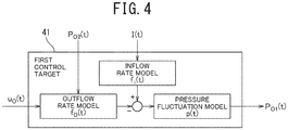
- the water electrolysis apparatus 1 when configured to accept the opening degree uo (t) of the oxygen pressure control valve 21, the outlet pressure P O2 (t) of the oxygen pressure control valve 21, and the current I (t) supplied to the electrolytic bath 2 as input and output the tank internal pressure P O1 (t) in the oxygen gas-liquid separation tank 3 is modeled as a control target (hereinafter, also referred to as "first control target 41").
- the model of the first control target 41 is configured to include an outflow rate model that represents an outflow rate f o (t) of the oxygen 11 from the oxygen gas-liquid separation tank 3, an inflow rate model that represents an inflow rate f i (t) of the oxygen 11 into the oxygen gas-liquid separation tank 3, and a pressure fluctuation model that represents pressure fluctuation p(t) of the tank internal pressure P O1 (t) in the oxygen gas-liquid separation tank 3.
- the outflow rate model is configured as expressed by the following equation (7), based on a unit conversion factor ⁇ , a CV value Cv max [-], a valve characteristic model m(uo) [-] of the oxygen pressure control valve 21, the tank internal pressure P O1 (t) [kPaG] in the oxygen gas-liquid separation tank 3, and the outlet pressure P O2 (t) [kPaG] of the oxygen pressure control valve 21.
- the valve characteristic model m(uo) is a function that represents characteristics of the oxygen pressure control valve 21 (for example, whether the opening degree u o (t) influences the flow rate of the oxygen 11 linearly or nonlinearly).
- the oxygen 11 does not flow out from the oxygen pressure control valve 21 unless a relationship that the outlet pressure P O2 (t) of the oxygen pressure control valve 21 is greater than the tank internal pressure P O1 (t) (inlet pressure of the oxygen pressure control valve 21) is maintained.
- the magnitude of the outflow rate of the oxygen 11 from the oxygen gas-liquid separation tank 3 changes. For example, as the outlet pressure P O2 (t) increases, the outflow rate of the oxygen 11 decreases.
- the tank internal pressure P O1 (t) increases, the outflow rate of the oxygen 11 increases.
- the inflow rate model is configured as expressed by the following equation (8), based on a conversion factor ⁇ , the temperature T O (t) of the water 10 in the oxygen generation portion, the tank internal pressure P O1 (t) in the oxygen gas-liquid separation tank 3, a first-order lag function 1/(T Ov s+1) that represents temporal characteristics until when the oxygen 11 generated in the electrolytic bath 2 influences the tank internal pressure P O1 (t) in the oxygen gas-liquid separation tank 3, and the current I(t) supplied to the electrolytic bath 2.
- the time constant T Ov of the first-order lag function 1/(T Ov s+1) is determined by means of data fitting.
- the larger the current I(t) supplied to the electrolytic bath 2 is, the larger the amount of generated oxygen 11 becomes and the larger the inflow rate f i (t) of the oxygen 11 into the oxygen gas-liquid separation tank 3 becomes.
- the higher the temperature T O (t) of the water 10 in the oxygen generation portion is, the larger the amount of generated oxygen 11 becomes and the larger the inflow rate f i (t) of the oxygen 11 into the oxygen gas-liquid separation tank 3 becomes.
- the lower the pressure P O1 (t) in the oxygen gas-liquid separation tank 3 is, the larger the amount of generated oxygen 11 becomes and the larger the inflow rate f i (t) of the oxygen 11 into the oxygen gas-liquid separation tank 3 becomes.
- the pressure fluctuation model is configured as expressed by the following equation (9), based on constant pressure p (having "-” thereabove), specific volume v (having "-” thereabove), the tank gas phase volume V O (L) of the oxygen gas-liquid separation tank 3, an integral 1/s, the inflow rate model, and the outflow rate model.
- G OP (S) is a transfer function obtained by Laplace-transforming p(t)
- G OI (s) is a transfer function obtained by Laplace-transforming f i (t)
- G OV1 (s) is a transfer function obtained by Laplace-transforming terms representing influence of u O (t) in the case where f o (t) is converted to an approximate expression made up of the terms representing influence of uo(t) and terms representing influence of P O2 (t) .
- G OV1 (s) is a transfer function obtained by Laplace-transforming the terms representing influence of P O2 (t).
- G OP (s) includes 1/V O (L)
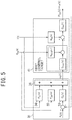
- the transfer function C O (s) of the controller of the first feedback control unit 33 is set as expressed by the following equation (22).
- the transfer functions C O (s), F OI (s), and F OP (s) of the controllers of the first feedback control, the first feedforward control, and the third feedforward control in the first opening degree adjustment unit 31 are derived.
- the controllers of the second feedback control, the second feedforward control, and the fourth feedforward control in the second opening degree adjustment unit 32 can also be derived in a similar manner. In so doing, the equations become ones with subscripts "O" of variables (except f O (t)) in the above-described equations (7) to (23) replaced with "H".
- the control of the opening degree u O (t) of the oxygen pressure control valve 21 includes the first feedback control for controlling the opening degree u O (t) of the oxygen pressure control valve 21, based on the tank internal pressure P O1 (t), which is detected by the first tank internal pressure detector 22, in such a way that a difference between the tank internal pressure P O1 (t) and the predetermined target pressure P O* (t) decreases and the first feedforward control for controlling the opening degree u O (t) of the oxygen pressure control valve 21, based on the current I(t), which is detected by the current detector 15.
- control of the opening degree u H (t) of the hydrogen pressure control valve 26 includes the second feedback control for controlling the opening degree u H (t) of the hydrogen pressure control valve 26, based on the tank internal pressure P H1 (t), which is detected by the second tank internal pressure detector 27, in such a way that a difference between the tank internal pressure P H1 (t) and the predetermined target pressure P H* (t) decreases and the second feedforward control for controlling the opening degree u H (t) of the hydrogen pressure control valve 26, based on the current I(t), which is detected by the current detector 15.
- the first feedforward control and the second feedforward control enable a difference between the tank internal pressure P O1 (t) in the oxygen gas-liquid separation tank 3 and the target pressure P O* (t) and a difference between the tank internal pressure P H1 (t) in the hydrogen gas-liquid separation tank 4 and the target pressure P H* (t) to be rapidly reduced.
- the water electrolysis apparatus 1 in which differential pressure between pressure of the oxygen 11 on the one surface 8a side of the electrolytic membrane 8 and pressure of the hydrogen 13 on the other surface 8b side of the electrolytic membrane 8 is more appropriately reduced. As a result, it is possible to appropriately prevent breakage of the electrolytic membrane 8.
- the first feedforward control controls the opening degree u O (t) of the oxygen pressure control valve 21 in such a way that the larger the current I(t), which is detected by the current detector 15, is, the larger the opening degree uo (t) of the oxygen pressure control valve 21 becomes.
- the second feedforward control controls the opening degree u H (t) of the hydrogen pressure control valve 26 in such a way that the larger the current I(t), which is detected by the current detector 15, is, the larger the opening degree u H (t) of the hydrogen pressure control valve 26 becomes.
- the higher the temperature T O (t) of the water 10 in the oxygen generation portion is, the larger the amount of generated oxygen 11 becomes and the larger the inflow rate f i (t) of the oxygen 11 into the oxygen gas-liquid separation tank 3 becomes, it is possible to suppress increase in the tank internal pressure P O1 (t) because the opening degree u O (t) of the oxygen pressure control valve 21 increases.
- the higher the temperature T H (t) of the water 10 in the hydrogen generation portion is, the larger the amount of generated hydrogen 13 becomes and the larger the inflow rate f i (t) of the hydrogen 13 into the hydrogen gas-liquid separation tank 4 becomes, it is possible to suppress increase in the tank internal pressure P H1 (t) because the opening degree u H (t) of the hydrogen pressure control valve 26 increases.
- the control of the opening degree u O (t) of the oxygen pressure control valve 21 includes the third feedforward control for controlling the opening degree u O (t) of the oxygen pressure control valve 21, based on the outlet pressure P O2 (t), which is detected by the first outlet pressure detector 23.
- the control of the opening degree u H (t) of the hydrogen pressure control valve 26 includes the fourth feedforward control for controlling the opening degree u H (t) of the hydrogen pressure control valve 26, based on the outlet pressure P H2 (t), which is detected by the second outlet pressure detector 28.
- the third feedforward control and the fourth feedforward control enable a difference between the tank internal pressure P O1 (t) in the oxygen gas-liquid separation tank 3 and the target pressure P O* (t) and a difference between the tank internal pressure P H1 (t) in the hydrogen gas-liquid separation tank 4 and the target pressure P H* (t) to be rapidly reduced.
- the third feedforward control controls the opening degree u O (t) of the oxygen pressure control valve 21 in such a way that the higher the outlet pressure P O2 (t), which is detected by the first outlet pressure detector 23, is, the larger the opening degree u O (t) of the oxygen pressure control valve 21 becomes .
- the fourth feedforward control controls the opening degree u H (t) of the hydrogen pressure control valve 26 in such a way that the higher the outlet pressure P H2 (t), which is detected by the second outlet pressure detector 28, is, the larger the opening degree u H (t) of the hydrogen pressure control valve 26 becomes.
Landscapes
- Chemical & Material Sciences (AREA)
- Engineering & Computer Science (AREA)
- Materials Engineering (AREA)
- Chemical Kinetics & Catalysis (AREA)
- Electrochemistry (AREA)
- Metallurgy (AREA)
- Organic Chemistry (AREA)
- Analytical Chemistry (AREA)
- Automation & Control Theory (AREA)
- Sustainable Development (AREA)
- Life Sciences & Earth Sciences (AREA)
- Inorganic Chemistry (AREA)
- Electrolytic Production Of Non-Metals, Compounds, Apparatuses Therefor (AREA)
Abstract
Description
- The present invention relates to a water electrolysis apparatus.
- Conventionally, water electrolysis apparatuses that electrolyze water, using an electrolytic membrane and generate oxygen and hydrogen on one surface side and the other surface side of the electrolytic membrane, respectively, have been proposed (see, for example, PTLs 1 to 3). Such a water electrolysis apparatus is configured to keep constant differential pressure between the pressure of oxygen on the one surface side of the electrolytic membrane and the pressure of hydrogen on the other surface side thereof in order to prevent breakage of the electrolytic membrane and keep low oxygen concentration in hydrogen and hydrogen concentration in oxygen.
-
- PTL 1:
JP 4000415 B - PTL 2:
JP H08-193287 A - PTL 3:
JP 2011-006769 A - Such a water electrolysis apparatus has been required to more appropriately reduce differential pressure on the electrolytic membrane.
- The present invention has been made in view of the circumstances described above, and an object of the present invention is to provide a water electrolysis apparatus that more appropriately reduces differential pressure on an electrolytic membrane.
- In order to achieve the above object, according to an aspect of the present invention, there is provided a water electrolysis apparatus including: (a) an electrolytic bath configured to electrolyze water, using an electrolytic membrane and generate oxygen and hydrogen on one surface side and the other surface side of the electrolytic membrane, respectively; (b) an oxygen gas-liquid separation tank configured to separate oxygen generated on the one surface side from water; (c) a conduit for oxygen disposed to the oxygen gas-liquid separation tank and including an oxygen pressure control valve; (d) a first opening degree adjustment unit configured to control an opening degree of the oxygen pressure control valve; (e) a hydrogen gas-liquid separation tank configured to separate hydrogen generated on the other surface side from water; (f) a conduit for hydrogen disposed to the hydrogen gas-liquid separation tank and including a hydrogen pressure control valve; (g) a second opening degree adjustment unit configured to control an opening degree of the hydrogen pressure control valve; (h) a first tank internal pressure detector configured to detect tank internal pressure in the oxygen gas-liquid separation tank; (i) a second tank internal pressure detector configured to detect tank internal pressure in the hydrogen gas-liquid separation tank; and (j) a current detector configured to detect current supplied to the electrolytic bath for the electrolysis, wherein (k) control of an opening degree of the oxygen pressure control valve includes first feedback control for controlling the opening degree of the oxygen pressure control valve, based on tank internal pressure detected by the first tank internal pressure detector in such a way that a difference between the tank internal pressure and a predetermined target pressure decreases and first feedforward control for controlling the opening degree of the oxygen pressure control valve, based on current detected by the current detector, and (1) control of an opening degree of the hydrogen pressure control valve includes second feedback control for controlling the opening degree of the hydrogen pressure control valve, based on tank internal pressure detected by the second tank internal pressure detector in such a way that a difference between the tank internal pressure and a predetermined target pressure decreases and second feedforward control for controlling the opening degree of the hydrogen pressure control valve, based on current detected by the current detector.
- According to the present invention, it is possible to provide a water electrolysis apparatus that more appropriately reduces differential pressure on an electrolytic membrane.
-
-
FIG. 1 is a configuration diagram of a water electrolysis apparatus according to an embodiment of the present invention; -
FIG. 2 is a block diagram illustrative of an internal configuration of a first opening degree adjustment unit; -
FIG. 3 is a block diagram illustrative of an internal configuration of a second opening degree adjustment unit; -
FIG. 4 is a block diagram illustrative of an internal configuration of a first control target; -
FIG. 5 is a block diagram illustrative of a configuration in which controllers of first feedback control, first feedforward control, and third feedforward control are applied to the first control target; -
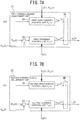
FIGS. 6A and 6B are diagrams illustrative of a first opening degree adjustment unit and a second opening degree adjustment unit according to a variation, andFIGS. 6A and 6B are block diagrams illustrative of internal configurations of the first opening degree adjustment unit and the second opening degree adjustment unit, respectively; -
FIGS. 7A and 7B are diagrams illustrative of a first opening degree adjustment unit and a second opening degree adjustment unit according to another variation, andFIGS. 7A and 7B are block diagrams illustrative of internal configurations of the first opening degree adjustment unit and the second opening degree adjustment unit, respectively; -
FIGS. 8A and 8B are diagrams illustrative of a first opening degree adjustment unit and a second opening degree adjustment unit according to still another variation, andFIGS. 8A and 8B are block diagrams illustrative of internal configurations of the first opening degree adjustment unit and the second opening degree adjustment unit, respectively; -
FIGS. 9A and 9B are diagrams illustrative of a first opening degree adjustment unit and a second opening degree adjustment unit according to still another variation, andFIGS. 9A and 9B are block diagrams illustrative of internal configurations of the first opening degree adjustment unit and the second opening degree adjustment unit, respectively; -
FIGS. 10A and 10B are diagrams illustrative of a first opening degree adjustment unit and a second opening degree adjustment unit according to still another variation, andFIGS. 10A and 10B are block diagrams illustrative of internal configurations of the first opening degree adjustment unit and the second opening degree adjustment unit, respectively; -
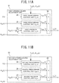
FIGS. 11A and 11B are diagrams illustrative of a first opening degree adjustment unit and a second opening degree adjustment unit according to still another variation, andFIGS. 11A and 11B are block diagrams illustrative of internal configurations of the first opening degree adjustment unit and the second opening degree adjustment unit, respectively; and -
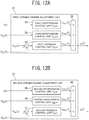
FIGS. 12A and 12B are diagrams illustrative of a first opening degree adjustment unit and a second opening degree adjustment unit according to still another variation, andFIGS. 12A and 12B are block diagrams illustrative of internal configurations of the first opening degree adjustment unit and the second opening degree adjustment unit, respectively. - A water electrolysis apparatus according to an embodiment of the present invention will now be described with reference to the drawings.
- The water electrolysis apparatus of the present embodiment is an apparatus that electrolyze water, using an electrolytic membrane, based on power that is generated using natural energy, such as wind force, sunlight, and terrestrial heat, which fluctuates irregularly.
- Note that the embodiment described below indicates a method and an apparatus to embody the technical idea of the present invention by way of example. Therefore, the embodiment does not limit the structures, arrangements, and the like of the constituent components in the technical idea of the present invention to those described below. In other words, the technical idea of the present invention can be subjected to various modifications within the technical scope defined by the claims set forth in CLAIMS.
- As illustrated in
FIG. 1 , a water electrolysis apparatus 1 according to an embodiment of the present invention includes an electrolytic bath 2, an oxygen gas-liquid separation tank 3, a hydrogen gas-liquid separation tank 4, and a computer 5. - The electrolytic bath 2 includes an
anode chamber 6 in which an anode is installed, acathode chamber 7 in which a cathode is installed, and anelectrolytic membrane 8 that partitions theanode chamber 6 from thecathode chamber 7. The electrolytic bath 2 electrolyzeswater 10, using theelectrolytic membrane 8, based onpower 9 supplied from a power generation apparatus (for example, a wind power generation apparatus, a solar power generation apparatus, or a geothermal power generation apparatus) that generates power using irregular natural energy, and generatesoxygen 11 in the anode chamber 6 (that is, a partition on the onesurface 8a side of theelectrolytic membrane 8, which is hereinafter also referred to as "oxygen generation portion"), using the anode. The generatedoxygen 11 andwater 10 are fed to the oxygen gas-liquid separation tank 3 via aconduit 12. On the other hand, the electrolytic bath 2 generateshydrogen 13 in the cathode chamber 7 (that is, a partition on theother surface 8b side of theelectrolytic membrane 8, which is hereinafter also referred to as "hydrogen generation portion"), using the cathode. The generatedhydrogen 13 andwater 10 are fed to the hydrogen gas-liquid separation tank 4 via aconduit 14. - As the
electrolytic membrane 8, an ion-permeableelectrolytic membrane 8 can be used in order to, while conducting ions, isolate hydrogen gas and oxygen gas from each other. As the ion-permeableelectrolytic membrane 8, it is preferable to use an electrolytic membrane that has, for example, low gas permeability, high ionic conductivity, low electronic conductivity, and high strength. For example, an ion exchange membrane that has ion exchange capacity or a porous membrane that allows an electrolytic solution to permeate therethrough can be used. - The porous membrane is a membranous member that has a plurality of fine through-holes and has a structure that allows an electrolytic solution to permeate the
electrolytic membrane 8. Since an electrolytic solution infiltrating into the porous membrane causes ionic conduction to appear, adjustment of a porous structure, such as pore diameter, porosity, and hydrophilicity, becomes substantially important. The porous membrane is required not only to allow an electrolytic solution to permeate therethrough but also not to allow generated gas to pass therethrough, that is, to have gas barrier properties. As such, from the perspective of gas barrier properties, adjustment of the porous structure also becomes important. - As the porous membrane, a membranous member, such as a polymer porous membrane, an inorganic porous membrane, a woven fabric, and a nonwoven fabric, can be used. These membranous members can be manufactured by a known technology. Examples of the manufacturing method of a polymer porous membrane include a phase conversion method (micro-phase separation method), an extraction method, a stretching method, and a wet gel spinning method.
- As a material of the porous membrane, it is preferable to use, for example, a material that includes a polymer material and hydrophilic inorganic particles. Including hydrophilic inorganic particles enables the porous membrane to be provided with hydrophilicity.
- Examples of the polymer material include polysulfone, polyether sulfone, polyphenylsulfone, polyvinylidene fluoride, polycarbonate, a tetrafluoroethylene-perfluoroalkyl vinyl ether copolymer, a tetrafluoroethylene-ethylene copolymer, polyvinylidene fluoride, polytetrafluoroethylene, perfluorosulfonic acid, perfluorocarboxylic acid, polyethylene, polypropylene, polyphenylene sulfide, polypara-phenylenebenzobisoxazole, polyketone, polyimide, and polyetherimide. Among the above-described materials, polysulfone, polyether sulfone, polyphenylsulfone, polyphenylene sulfide, or polytetrafluoroethylene is preferably used and polysulfone is more preferably used. One type of the materials may be used alone, or two or more types of materials may be used in combination. In other words, a composite polymer material in which two or more types of materials are mixed may be used.
- It is preferable to adjust the pore diameter of the porous membrane in order to achieve appropriate membrane physical properties, such as separation capacity and strength. When the porous membrane is used in alkaline water electrolysis, it is also preferable to adjust the pore diameter from perspectives of preventing mixing of oxygen gas generated from an anode 2a and hydrogen gas generated from a cathode 2c and reducing voltage loss in the electrolysis . For example, there is a tendency that, the larger the average pore diameter of the porous membrane is, the larger the permeation amount of the porous membrane per unit area becomes and, particularly in the electrolysis, the more excellent the ion permeability of the porous membrane becomes, which facilitates reduction in the voltage loss. In addition, there is a tendency that, the larger the average pore diameter of the porous membrane is, the smaller the contact surface area with alkaline water becomes, which causes deterioration of polymer to be suppressed.
- On the other hand, there is a tendency that, the smaller the average pore diameter of the porous membrane is, the higher the separation precision of the porous membrane becomes and the more excellent the gas barrier properties of the porous membrane becomes. Further, when hydrophilic inorganic particles having a small particle size, which will be described later, are supported on the porous membrane, it is possible to hold the hydrophilic inorganic particles without missing particles. This capability enables high retention capacity that the hydrophilic inorganic particles have to be provided and the effect thereof to be maintained for a long period of time.
- From such a perspective, the average pore diameter of the porous membrane is preferably in a range of 0.1 µm or more and 1.0 µm or less. When the pore diameter is in this range, the porous membrane is capable of achieving both excellent gas barrier properties and high ion permeability at the same time. The pore diameter of the porous membrane is preferably adjusted in an actual use temperature range. For example, when the porous membrane is used in alkaline water electrolysis under an environment of 90°C, the above-described requirement for the pore diameter range is preferably satisfied at 90°C. When the porous membrane is used in alkaline water electrolysis, the average pore diameter of the porous membrane is more preferably in a range of 0.1 µm or more and 0.5 µm or less as a range enabling more excellent gas barrier properties and higher ion permeability to appear.
- As the average pore diameter of the porous membrane of the present embodiment, an average permeable pore diameter measured by the following method using an integrity tester ("Sartocheck Junior BP-Plus" manufactured by Sartorius Stedim Japan K.K.) is used. In the measurement of an average permeable pore diameter, first, a sample of a predetermined size including a core material is cut from the porous membrane. Next, the sample is set in any pressure-resistant container and the pressure-resistant container is filled with pure water. Next, the pressure-resistant container is held in a thermostatic chamber set at a predetermined temperature and measurement is started after the inside of the pressure-resistant container has reached the predetermined temperature. When the measurement begins, since the upper surface side of the sample becomes pressurized with nitrogen and pure water permeates through the sample from the under surface side to the upper surface side of the sample, numerical values of pressure on the upper surface side of the sample and a permeation flow rate of pure water permeating the sample when the pure water permeates through the sample are recorded. The average permeable pore diameter can be calculated from the following Hagen-Poiseuille equation, using a gradient between the pressure and the water permeation flow rate for a pressure range between 10 kPa and 30 kPa.

- In the above equation, η is viscosity (Pa·s) of water, L is thickness (m) of the porous membrane, µ0 is apparent flow velocity, ε is porosity, and P is pressure (Pa).
- When the porous membrane is used in alkaline water electrolysis, it is preferable to adjust the porosity of the porous membrane from the perspectives of maintaining gas barrier properties and hydrophilicity, preventing deterioration in ion permeability due to attachment of bubbles, and being able to acquire stable electrolysis performance (low voltage loss and the like) for a long period of time. In particular, from the perspective of achieving both the gas barrier properties and low voltage loss at the same time at a high level, a lower limit of the porosity of the porous membrane is preferably 30% or more, more preferably 35% or more, and still more preferably 40% or more. In addition, an upper limit of the porosity is preferably 70% or less, more preferably 65% or less, and still more preferably 55% or less. When the porosity of the porous membrane is the above-described upper limit or less, ions are likely to permeate the membrane and it is possible to suppress voltage loss across the membrane.
- As the porosity of the porous membrane of the present embodiment, open porosity that is calculated by the Archimedes' method is used. The open porosity can be calculated by the following equation.


- In the above equation, W1, W2, and W3 are dry mass (g), underwater mass (g), and water saturated mass (g) of the porous membrane, respectively.
- In the measurement of the porosity, first, three samples each of which has a size of 3 cm by 3 cm are cut from a porous membrane that is washed by pure water, and values of W2 and W3 of the three samples are measured. Next, after leaving the three samples in a dryer the temperature of which is set at 50°C for 12 hours or more and thereby drying the three samples, values of W1 of the three samples are measured. The open porosity can be calculated by the above-described equation, using the measured values of W1, W2, and W3. An arithmetic mean value of the respective open porosities of the three samples is used as the porosity.
- The thickness of the porous membrane, although not specifically limited, is preferably 100 µm or more and 700 µm or less, more preferably 100 µm or more and 600 µm or less, and still more preferably 200 µm or more and 600 µm or less. When the thickness of the porous membrane is 100 µm or more, the porous membrane is hard to be torn by piercing or the like, the electrodes are hard to be short-circuited, and gas barrier properties become excellent. When the thickness of the porous membrane is 600 µm or less, voltage loss is hard to increase and influence of variation in the thickness decreases.
- When the thickness of the porous membrane is 250 µm or more, it is possible to acquire more excellent gas barrier properties and further improve the strength of the porous membrane against impact. From this perspective, the lower limit of the thickness of the porous membrane is more preferably 300 µm or more, still more preferably 350 µm or more, and further still more preferably 400 µm or more. On the other hand, when the thickness of the porous membrane is 700 µm or less, the ion permeability is hard to be inhibited by resistance of the electrolytic solution contained in the pores at the time of operation and it is possible to maintain more excellent ion permeability. From this perspective, the upper limit of the thickness of the porous membrane is more preferably 600 µm or less, still more preferably 550 µm or less, and further still more preferably 500 µm or less.
- The porous membrane preferably contains hydrophilic inorganic particles in order to make high ion permeability and high gas barrier properties appear. As a method for making the porous membrane contain hydrophilic inorganic particles, for example, a method of attaching hydrophilic inorganic particles on the surfaces of the porous membrane, a method of embedding some of hydrophilic inorganic particles inside the porous membrane, or a method of making the porous membrane contain hydrophilic inorganic particles in a cavity portion thereof can be used. The method of making the porous membrane contain hydrophilic inorganic particles in the cavity portion thereof enables the hydrophilic inorganic particles to become hard to desorb from the cavity of the porous membrane and high ion permeability and high gas barrier properties of the porous membrane to be maintained for a long period of time.
- Examples of the hydrophilic inorganic particles include at least one type of inorganic substance chosen from a group made up of an oxide or a hydroxide of zirconium, bismuth, or cerium, an oxide of a group IV element of the periodic table, a nitride of a group IV element of the periodic table, and a carbide of a group IV element of the periodic table. From the perspective of chemical stability, among the above-described substances, an oxide of zirconium, bismuth, or cerium or an oxide of a group IV element of the periodic table is preferably used, an oxide of zirconium, bismuth, or cerium is more preferably used, and zirconium oxide is still more preferably used. The forms of the hydrophilic inorganic particles is preferably, for example, fine particle shapes.
- In the electrolytic bath 2, a
current detector 15 configured to detect current I(t) that is supplied to the electrolytic bath 2 for the electrolysis of thewater 10 andtemperature detectors 16 configured to detect temperatures TO(t) and TH(t) of thewater 10 in the electrolytic bath 2 are disposed. As used herein, the temperature To(t) is temperature of thewater 10 in the vicinity of the anode in theanode chamber 6. In other words, the temperature To(t) is temperature of thewater 10 in the oxygen generation portion. In addition, the temperature TH(t) is temperature of thewater 10 in the vicinity of the cathode in thecathode chamber 7. In other words, the temperature TH(t) is temperature of thewater 10 in the hydrogen generation portion. Detection results of the current I(t) and the temperatures TO(t) and TH(t) are input to the computer 5. - The oxygen gas-
liquid separation tank 3 stores theoxygen 11 and thewater 10 fed from the electrolytic bath 2. In the oxygen gas-liquid separation tank 3, thewater 10 and theoxygen 11 are positioned on the lower side and the upper side, respectively, and the storedoxygen 11 andwater 10 are separated. With the bottom end side of the oxygen gas-liquid separation tank 3, aconduit 17 for water that communicates with the feed water inlet side of the electrolytic bath 2 is communicated. Thewater 10 in the oxygen gas-liquid separation tank 3 is supplied to theanode chamber 6 and thecathode chamber 7 in the electrolytic bath 2 via theconduit 17 for water. Thewater 10 that has decreased due to electrolysis and the like is replenished from the outside via awater supply pump 18. - In the oxygen gas-
liquid separation tank 3, a firstwater level detector 19 configured to detect a water level LO(t) in the oxygen gas-liquid separation tank 3 is installed. A detection result of the water level Lo(t) is input to the computer 5. - With the top end side of the oxygen gas-
liquid separation tank 3, aconduit 20 for oxygen for taking out theoxygen 11 to the outside is communicated. In theconduit 20 for oxygen, an oxygen pressure control valve 21 that is capable of adjusting a flow rate in theconduit 20 for oxygen is disposed. The oxygen pressure control valve 21 controls an opening degree uo(t) of the oxygen pressure control valve 21 in accordance with a signal from the computer 5. - Further, in the oxygen gas-
liquid separation tank 3, a first tankinternal pressure detector 22 configured to detect tank internal pressure PO1(t) from theoxygen 11 in the oxygen gas-liquid separation tank 3 is arranged. A detection result (tank internal pressure PO1(t)) by the first tankinternal pressure detector 22 is input to the computer 5. - In addition, on the outlet side of the oxygen pressure control valve 21 in the
conduit 20 for oxygen, a first outlet pressure detector 23 configured to detect outlet pressure PO2(t) of the oxygen pressure control valve 21 is arranged. A detection result (outlet pressure PO2(t)) by the first outlet pressure detector 23 is input to the computer 5. - The hydrogen gas-
liquid separation tank 4 stores thehydrogen 13 and thewater 10 fed from the electrolytic bath 2. In the hydrogen gas-liquid separation tank 4, thewater 10 and thehydrogen 13 are positioned on the lower side and the upper side, respectively, and the storedhydrogen 13 andwater 10 are separated. With the bottom end side of the hydrogen gas-liquid separation tank 4, theconduit 17 for water is communicated, as with the oxygen gas-liquid separation tank 3. Thewater 10 stored in the hydrogen gas-liquid separation tank 4 is also supplied to theanode chamber 6 and thecathode chamber 7 via theconduit 17 for water. - In the hydrogen gas-
liquid separation tank 4, a secondwater level detector 24 configured to detect a water level LH(t) in the hydrogen gas-liquid separation tank 4 is installed. A detection result of the water level LH(t) is input to the computer 5. - Note that, since the inside of the oxygen gas-
liquid separation tank 3 and the inside of the hydrogen gas-liquid separation tank 4 are communicated with each other by theconduit 17 for water, water surface levels in both gas-liquid separation tanks are kept at substantially the same level. - With the top end side of the hydrogen gas-
liquid separation tank 4, aconduit 25 for hydrogen for taking out thehydrogen 13 to the outside is communicated. In theconduit 25 for hydrogen, a hydrogenpressure control valve 26 that is capable of adjusting a flow rate in theconduit 25 for hydrogen is disposed. The hydrogenpressure control valve 26 controls an opening degree uH(t) of the hydrogenpressure control valve 26 in accordance with a signal from the computer 5. - Further, in the hydrogen gas-
liquid separation tank 4, a second tankinternal pressure detector 27 configured to detect tank internal pressure PH1(t) from thehydrogen 13 in the hydrogen gas-liquid separation tank 4 is arranged. A detection result (tank internal pressure PH1(t)) of the second tankinternal pressure detector 27 is input to the computer 5. - In addition, on the outlet side of the hydrogen
pressure control valve 26 in theconduit 25 for hydrogen, a secondoutlet pressure detector 28 configured to detect outlet pressure PH2(t) of the hydrogenpressure control valve 26 is arranged. A detection result (outlet pressure PH2(t)) by the secondoutlet pressure detector 28 is input to the computer 5. - The computer 5 includes hardware resources, such as a
storage device 29 and aprocessor 30. - The
storage device 29 stores control programs for the computer 5 that can be executed by theprocessor 30. Thestorage device 29 also stores various types of data that are necessary for the execution of the control programs. - The
processor 30 reads control programs from thestorage device 29 and achieves a first openingdegree adjustment unit 31 configured to control the opening degree uo (t) of the oxygen pressure control valve 21, a second openingdegree adjustment unit 32 configured to control the opening degree uH(t) of the hydrogenpressure control valve 26, and the like. The first openingdegree adjustment unit 31 includes a firstfeedback control unit 33, a firstfeedforward control unit 34, a thirdfeedforward control unit 35, and a first summingunit 36, as illustrated inFIG. 2 . The second openingdegree adjustment unit 32 includes a secondfeedback control unit 37, a secondfeedforward control unit 38, a fourthfeedforward control unit 39, and a second summingunit 40, as illustrated inFIG. 3 . - The first
feedback control unit 33 performs first feedback control for controlling the opening degree uo(t) (hereinafter, also referred to as "uOFB1(t)") of the oxygen pressure control valve 21, based on the tank internal pressure PO1(t) in the oxygen gas-liquid separation tank 3, which is detected by the first tankinternal pressure detector 22, in such a way that a difference between the tank internal pressure PO1(t) and a predetermined target pressure PO*(t) decreases. Specifically, as expressed by the following equation (1), a numerical value of the opening degree uOFB1(t) of the oxygen pressure control valve 21 is calculated by inputting the detected tank internal pressure PO1(t) to a transfer function CO(s) of a controller of the firstfeedback control unit 33 that takes the tank internal pressure Poi(t) in the oxygen gas-liquid separation tank 3 as input and gives the opening degree uOFB1(t) of the oxygen pressure control valve 21 as output.
- In the equation, Vo(L) is tank gas phase volume of the oxygen gas-
liquid separation tank 3 that is calculated based on the water level Lo(t) in the oxygen gas-liquid separation tank 3, which is detected by the firstwater level detector 19. In addition, KOp is a proportional gain, KOI is an integral gain, KOD is a differential gain, and s is a Laplace operator. - By using the transfer function CO(s) as described above, in the first feedback control, PID control is performed and, in conjunction therewith, the higher the water level LO(t), which is detected by the first
water level detector 19, is, the smaller PID gains VO(L)·KOp, VO(L)·KOI, and VO(L)·KOD of the PID control are set. - A calculated numerical value of the opening degree uOFB1(t) of the oxygen pressure control valve 21 is output to the first summing
unit 36. - The first
feedforward control unit 34 performs first feedforward control for controlling the opening degree uO(t) (hereinafter, also referred to as "uOFF1(t) ") of the oxygen pressure control valve 21, based on the current I(t), which is detected by thecurrent detector 15. Specifically, as expressed by the following equation (2), a numerical value of the opening degree uOFF1(t) of the oxygen pressure control valve 21 is calculated by inputting the detected current I(t) to a transfer function FOI(s) of a controller of the firstfeedforward control unit 34 that takes the current I(t) supplied to the electrolytic bath 2 as input and gives the opening degree uOFF1(t) of the oxygen pressure control valve 21 as output.
[Math 1]
- In the equation, TO(t) is temperature of the
water 10 in the electrolytic bath 2, which is detected by thetemperature detector 16. Further, PO1(t) is tank internal pressure in the oxygen gas-liquid separation tank 3, which is detected by the first tankinternal pressure detector 22. In addition, other parameters Poi (having "-" thereabove), PO2 (having "-" thereabove) , αO, τO, and TOv are fixed values used in the transfer functions GOV1 and GOI, which will be described later. - By using the transfer function FOI (s) as described above, in the first feedforward control, the opening degree uOFF1 (t) of the oxygen pressure control valve 21 is controlled in such a way that the larger the current I(t), which is detected by the
current detector 15, is, the larger the opening degree uOFF1(t) of the oxygen pressure control valve 21 becomes. In addition, the higher the temperature To(t) of thewater 10 in the oxygen generation portion, which is detected by thetemperature detector 16, is, the larger the gain of the controller performing the first feedforward control is set. Further, the higher the tank internal pressure PO1(t), which is detected by the first tankinternal pressure detector 22, is, the smaller the gain of the controller performing the first feedforward control is set. - A calculated numerical value of the opening degree uOFF1 of the oxygen pressure control valve 21 is output to the first summing
unit 36. - The third
feedforward control unit 35 performs third feedforward control for controlling the opening degree uO(t) (hereinafter, also referred to as "uOFF3(t)") of the oxygen pressure control valve 21, based on the outlet pressure PO2(t), which is detected by the first outlet pressure detector 23. Specifically, as expressed by the following equation (3), a numerical value of the opening degree uOFF3(t) of the oxygen pressure control valve 21 is calculated by inputting the detected outlet pressure PO2(t) to a transfer function FOP(s) of a controller of the thirdfeedforward control unit 35 that takes the outlet pressure PO2(t) of the oxygen pressure control valve 21 as input and gives the opening degree uOFF3(t) of the oxygen pressure control valve 21 as output.
[Math 2]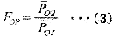
- By using the transfer function FOP(s) as described above, in the third feedforward control, the opening degree uOFF3(t) of the oxygen pressure control valve 21 is controlled in such a way that the higher the outlet pressure PO2(t), which is detected by the first outlet pressure detector 23, is, the larger the opening degree uOFF3(t) of the oxygen pressure control valve 21 becomes.
- A calculated numerical value of the opening degree uOFF3(t) of the hydrogen
pressure control valve 26 is output to the first summingunit 36. - The first summing
unit 36 sums numerical values of the opening degrees uOFB1(t), uOFF1(t), and uOFF3(t) of the hydrogenpressure control valve 26, which are output from the firstfeedback control unit 33, the firstfeedforward control unit 34, and the thirdfeedforward control unit 35, respectively. A signal that indicates the sum result uo(t) is output to the oxygen pressure control valve 21. Based on the signal, the oxygen pressure control valve 21 adjusts the opening degree uo(t) of the oxygen pressure control valve 21 in accordance with the output signal in such a way that the sum result is achieved. - The second
feedback control unit 37 performs second feedback control for controlling the opening degree uH(t) (hereinafter, also referred to as "uHFB2(t)") of the hydrogenpressure control valve 26, based on the tank internal pressure PH1(t) in the hydrogen gas-liquid separation tank 4, which is detected by the second tankinternal pressure detector 27, in such a way that a difference between the tank internal pressure PH1(t) and a predetermined target pressure PH*(t) decreases. It is assumed that the target pressure PH*(t) is the same as the target pressure PO*(t) or approximately slightly greater than the target pressure PO* (t)(PH*(t)≥PO*(t) and PH*(t)-PO*(t)≅0). Specifically, as expressed by the following equation (4), a numerical value of the opening degree uHFB2(t) of the hydrogenpressure control valve 26 is calculated by inputting the detected tank internal pressure PH1(t) to a transfer function CH(s) of a controller of the secondfeedback control unit 37 that takes the tank internal pressure PH1(t) in the hydrogen gas-liquid separation tank 4 as input and gives the opening degree uHFB2(t) of the hydrogenpressure control valve 26 as output.
- In the equation, VH(L) is tank gas phase volume of the hydrogen gas-
liquid separation tank 4 that is calculated based on the water level LH(t) in the hydrogen gas-liquid separation tank 4, which is detected by the secondwater level detector 24. In addition, KHP is a proportional gain, KHI is an integral gain, and KHD is a differential gain. - By using the transfer function CH(s) as described above, in the second feedback control, PID control is performed and, in conjunction therewith, the higher the water level LH(t), which is detected by the second
water level detector 24, is, the smaller PID gains VH(L)·KHp, VH(L)·KHI, and VH(L)·KHD are set. A calculated numerical value of the opening degree uHFB2(t) of the hydrogenpressure control valve 26 is output to the second summingunit 40. - The second
feedforward control unit 38 performs second feedforward control for controlling the opening degree uH(t) (hereinafter, also referred to as "uHFF2(t) ") of the hydrogenpressure control valve 26, based on the current I(t), which is detected by thecurrent detector 15. Specifically, as expressed by the following equation (5), a numerical value of the opening degree uHFF2(t) of the hydrogenpressure control valve 26 is calculated by inputting the detected current I(t) to a transfer function FHI(s) of a controller of the secondfeedforward control unit 38 that takes the current I(t) supplied to the electrolytic bath 2 as input and gives the opening degree uHFF2(t) of the hydrogenpressure control valve 26 as output.
[Math 3]
- In the equation, PH1(t) is tank internal pressure in the hydrogen gas-
liquid separation tank 4, which is detected by the second tankinternal pressure detector 27. In addition, other parameters PH1 (having "-" thereabove), PH2 (having "-" thereabove), αH, τH, and THV are fixed values used in the transfer functions GHV1 and GHI, which will be described later. - By using the transfer function FHI (s) as described above, in the second feedforward control, the opening degree uHFF1(t) of the hydrogen
pressure control valve 26 is controlled in such a way that the larger the current I(t), which is detected by thecurrent detector 15, is, the larger the opening degree uHFF2(t) of the hydrogenpressure control valve 26 becomes. In addition, the higher the temperature TH(t) of thewater 10 in the hydrogen generation portion, which is detected by thetemperature detector 16, is, the larger the gain of the controller performing the second feedforward control is set. Further, the higher the tank internal pressure PH1(t), which is detected by the second tankinternal pressure detector 27, is, the smaller the gain of the controller performing the second feedforward control is set. - A calculated numerical value of the opening degree uHFF2(t) of the hydrogen
pressure control valve 26 is output to the second summingunit 40. - The fourth
feedforward control unit 39 performs fourth feedforward control for controlling the opening degree uO(t) (hereinafter, also referred to as "uHFF4(t)") of the hydrogenpressure control valve 26, based on the outlet pressure PH2(t), which is detected by the secondoutlet pressure detector 28. Specifically, as expressed by the following equation (6), a numerical value of the opening degree uHFF4(t) of the hydrogenpressure control valve 26 is calculated by inputting the detected outlet pressure PH2(t) to a transfer function FHP(s) of a controller of the fourthfeedforward control unit 39 that takes the outlet pressure PH2(t) of the hydrogenpressure control valve 26 as input and gives the opening degree uHFF4(t) of the hydrogenpressure control valve 26 as output.
[Math 4]
- By using the transfer function FHP(s) as described above, in the fourth feedforward control, the opening degree uHFF4(t) of the hydrogen
pressure control valve 26 is controlled in such a way that the higher the outlet pressure PH2(t), which is detected by the secondoutlet pressure detector 28, is, the larger the opening degree uHFF4(t) of the hydrogenpressure control valve 26 becomes. - A calculated numerical value of the opening degree uHFF4(t) of the hydrogen
pressure control valve 26 is output to the second summingunit 40. - The second summing
unit 40 sums numerical values of the opening degrees uHFB2(t), uHFF2(t), and uHFF4(t) of the hydrogenpressure control valve 26, which are output from the secondfeedback control unit 37, the secondfeedforward control unit 38, and the fourthfeedforward control unit 39, respectively. A signal that indicates the sum result uH(t) is output to the hydrogenpressure control valve 26. Based on the signal, the hydrogenpressure control valve 26 adjusts the opening degree uH(t) of the hydrogenpressure control valve 26 in accordance with the output signal in such a way that the sum result is achieved. - Next, a derivation method of the transfer functions CO(s), FOI(s), and FOP(s) of the controllers of the first
feedback control unit 33, the firstfeedforward control unit 34, and the thirdfeedforward control unit 35 in the first openingdegree adjustment unit 31 will be described with reference to the drawings. - First, as illustrated in
FIG. 4 , the water electrolysis apparatus 1 when configured to accept the opening degree uo (t) of the oxygen pressure control valve 21, the outlet pressure PO2(t) of the oxygen pressure control valve 21, and the current I (t) supplied to the electrolytic bath 2 as input and output the tank internal pressure PO1(t) in the oxygen gas-liquid separation tank 3 is modeled as a control target (hereinafter, also referred to as "first control target 41"). The model of thefirst control target 41 is configured to include an outflow rate model that represents an outflow rate fo(t) of theoxygen 11 from the oxygen gas-liquid separation tank 3, an inflow rate model that represents an inflow rate fi(t) of theoxygen 11 into the oxygen gas-liquid separation tank 3, and a pressure fluctuation model that represents pressure fluctuation p(t) of the tank internal pressure PO1(t) in the oxygen gas-liquid separation tank 3. - The outflow rate model is configured as expressed by the following equation (7), based on a unit conversion factor α, a CV value Cvmax [-], a valve characteristic model m(uo) [-] of the oxygen pressure control valve 21, the tank internal pressure PO1(t) [kPaG] in the oxygen gas-
liquid separation tank 3, and the outlet pressure PO2(t) [kPaG] of the oxygen pressure control valve 21. The valve characteristic model m(uo) is a function that represents characteristics of the oxygen pressure control valve 21 (for example, whether the opening degree uo(t) influences the flow rate of theoxygen 11 linearly or nonlinearly).
[Math 5]
- According to the above-described equation (7), the
oxygen 11 does not flow out from the oxygen pressure control valve 21 unless a relationship that the outlet pressure PO2(t) of the oxygen pressure control valve 21 is greater than the tank internal pressure PO1(t) (inlet pressure of the oxygen pressure control valve 21) is maintained. In addition, when a difference between the outlet pressure PO2(t) of the oxygen pressure control valve 21 and the tank internal pressure PO1(t) changes, the magnitude of the outflow rate of theoxygen 11 from the oxygen gas-liquid separation tank 3 changes. For example, as the outlet pressure PO2(t) increases, the outflow rate of theoxygen 11 decreases. On the other hand, as the tank internal pressure PO1(t) increases, the outflow rate of theoxygen 11 increases. - The inflow rate model is configured as expressed by the following equation (8), based on a conversion factor τ, the temperature TO(t) of the
water 10 in the oxygen generation portion, the tank internal pressure PO1(t) in the oxygen gas-liquid separation tank 3, a first-order lag function 1/(TOvs+1) that represents temporal characteristics until when theoxygen 11 generated in the electrolytic bath 2 influences the tank internal pressure PO1(t) in the oxygen gas-liquid separation tank 3, and the current I(t) supplied to the electrolytic bath 2. The time constant TOv of the first-order lag function 1/(TOvs+1) is determined by means of data fitting.
[Math 6]
- According to the above-described equation (8), the larger the current I(t) supplied to the electrolytic bath 2 is, the larger the amount of generated
oxygen 11 becomes and the larger the inflow rate fi(t) of theoxygen 11 into the oxygen gas-liquid separation tank 3 becomes. In addition, the higher the temperature TO(t) of thewater 10 in the oxygen generation portion is, the larger the amount of generatedoxygen 11 becomes and the larger the inflow rate fi(t) of theoxygen 11 into the oxygen gas-liquid separation tank 3 becomes. Further, the lower the pressure PO1(t) in the oxygen gas-liquid separation tank 3 is, the larger the amount of generatedoxygen 11 becomes and the larger the inflow rate fi(t) of theoxygen 11 into the oxygen gas-liquid separation tank 3 becomes. - The pressure fluctuation model is configured as expressed by the following equation (9), based on constant pressure p (having "-" thereabove), specific volume v (having "-" thereabove), the tank gas phase volume VO (L) of the oxygen gas-
liquid separation tank 3, an integral 1/s, the inflow rate model, and the outflow rate model.
[Math 7]
- According to the above-described equation (9), the larger the inflow rate fi(t) into the the oxygen gas-
liquid separation tank 3 is, the larger the pressure fluctuation p (t) in the oxygen gas-liquid separation tank 3 becomes. In addition, the smaller the outflow rate fo(t) from the the oxygen gas-liquid separation tank 3 is, the larger the pressure fluctuation p (t) in the oxygen gas-liquid separation tank 3 becomes. Further, the smaller the tank gas phase volume VO(L) is, the faster the pressure fluctuation p(t) (fluctuation in the tank internal pressure PO1(t)) becomes. In addition, the larger the tank gas phase volume VO(L) is, the slower the pressure fluctuation p(t) becomes. - Succeedingly, as illustrated in
FIG. 5 , an equation of the tank internal pressure PO1(t) (hereinafter, also referred to as "y(t)") in the oxygen gas-liquid separation tank 3 in the case where the controllers (the transfer functions CO(s), FOI(s), and FOP(s)) of the first feedback control, the first feedforward control, and the third feedforward control are applied to the model of thefirst control target 41 expressed by the above-described equations (7) to (9) is derived.
[Math 8]
- In this equation, GOP(S) is a transfer function obtained by Laplace-transforming p(t), and GOI(s) is a transfer function obtained by Laplace-transforming fi(t) . GOV1(s) is a transfer function obtained by Laplace-transforming terms representing influence of uO(t) in the case where fo(t) is converted to an approximate expression made up of the terms representing influence of uo(t) and terms representing influence of PO2(t) . GOV1(s) is a transfer function obtained by Laplace-transforming the terms representing influence of PO2(t).
- According to the above-described equation (10), in order to reduce influence of I(t) on the tank internal pressure y(t) in the oxygen gas-
liquid separation tank 3, it is only required to satisfy the following equation (11). Therefore, the transfer function FOI(s) of the controller of the firstfeedforward control unit 34 is set as expressed by the following equation (12).
[Math 9]
- In these equations, the transfer functions GOP(s), GOI(s), GOV1(s), and GOV2(s) are expressed by the following equations (13), (14), (15), and (16), respectively.
[Math 10]
- According to the above-described equations (13) to (16), the above-described equation (12) expressing the transfer function FOI(s) of the controller of the first
feedforward control unit 34 is set as expressed by the following equation (17) .
[Math 11]
- According to the above-described equation (10), in order to reduce influence of PO2(t) on the tank internal pressure y(t) in the oxygen gas-
liquid separation tank 3, it is only required to satisfy the following equation (18). Therefore, the transfer function FOP(s) of the controller of the thirdfeedforward control unit 35 is set as expressed by the following equation (19).
[Math 12]
- According to the above-described equations (13) to (16), the above-described equation (12) expressing the transfer function FOP(s) of the controller of the third
feedforward control unit 35 is set as expressed by the following equation (20) .
[Math 13]
- Further, when the transfer function FOI(s) expressed by the above-described equation (12) and the transfer function FOP(s) expressed by the above-described equation (19) are employed, the above-described equation (10) expressing the tank internal pressure y(t) in the oxygen gas-
liquid separation tank 3 is set as expressed by the following equation (21).
[Math 14]
- Since, in the above-described equation (21), GOP(s) includes 1/VO(L), it is only required to multiply the entire transfer function Co(s) of the controller of the first
feedback control unit 33 by VO(L) in order to reduce influence of fluctuation in 1/VO(L) on closed-loop transfer characteristics. Therefore, the transfer function CO(s) of the controller of the firstfeedback control unit 33 is set as expressed by the following equation (22).
[Math 15]
- When GOp(s) expressed by the above-described equation (13) and CO(s) expressed by the above-described equation (22) are employed, the above-described equation (21) expressing the tank internal pressure y(t) in the oxygen gas-
liquid separation tank 3 is deformed as in the following equation (23) .
[Math 16]
- In accordance with the above-described procedure, the transfer functions CO(s), FOI(s), and FOP(s) of the controllers of the first feedback control, the first feedforward control, and the third feedforward control in the first opening
degree adjustment unit 31 are derived. The controllers of the second feedback control, the second feedforward control, and the fourth feedforward control in the second openingdegree adjustment unit 32 can also be derived in a similar manner. In so doing, the equations become ones with subscripts "O" of variables (except fO(t)) in the above-described equations (7) to (23) replaced with "H". - As described in the foregoing, in the water electrolysis apparatus 1 according to the embodiment of the present invention, the control of the opening degree uO(t) of the oxygen pressure control valve 21 includes the first feedback control for controlling the opening degree uO(t) of the oxygen pressure control valve 21, based on the tank internal pressure PO1(t), which is detected by the first tank
internal pressure detector 22, in such a way that a difference between the tank internal pressure PO1(t) and the predetermined target pressure PO*(t) decreases and the first feedforward control for controlling the opening degree uO(t) of the oxygen pressure control valve 21, based on the current I(t), which is detected by thecurrent detector 15. In addition, the control of the opening degree uH(t) of the hydrogenpressure control valve 26 includes the second feedback control for controlling the opening degree uH(t) of the hydrogenpressure control valve 26, based on the tank internal pressure PH1(t), which is detected by the second tankinternal pressure detector 27, in such a way that a difference between the tank internal pressure PH1(t) and the predetermined target pressure PH*(t) decreases and the second feedforward control for controlling the opening degree uH(t) of the hydrogenpressure control valve 26, based on the current I(t), which is detected by thecurrent detector 15. - Therefore, when, for example, the current I(t) supplied to the electrolytic bath 2 changes, the first feedforward control and the second feedforward control enable a difference between the tank internal pressure PO1(t) in the oxygen gas-
liquid separation tank 3 and the target pressure PO*(t) and a difference between the tank internal pressure PH1(t) in the hydrogen gas-liquid separation tank 4 and the target pressure PH*(t) to be rapidly reduced. As such, it is possible to provide the water electrolysis apparatus 1 in which differential pressure between pressure of theoxygen 11 on the onesurface 8a side of theelectrolytic membrane 8 and pressure of thehydrogen 13 on theother surface 8b side of theelectrolytic membrane 8 is more appropriately reduced. As a result, it is possible to appropriately prevent breakage of theelectrolytic membrane 8. - In the water electrolysis apparatus 1 according to the embodiment of the present invention, the first feedforward control controls the opening degree uO(t) of the oxygen pressure control valve 21 in such a way that the larger the current I(t), which is detected by the
current detector 15, is, the larger the opening degree uo (t) of the oxygen pressure control valve 21 becomes. In addition, the second feedforward control controls the opening degree uH(t) of the hydrogenpressure control valve 26 in such a way that the larger the current I(t), which is detected by thecurrent detector 15, is, the larger the opening degree uH(t) of the hydrogenpressure control valve 26 becomes. Therefore, although the larger the current I(t) is, the larger the amount of generatedoxygen 11 becomes and the larger the inflow rate fi(t) of theoxygen 11 into the oxygen gas-liquid separation tank 3 becomes, it is possible to suppress increase in the tank internal pressure PO1(t) because the opening degree uo (t) of the oxygen pressure control valve 21 increases. Although the larger the current I(t) is, the larger the amount of generatedhydrogen 13 becomes and the larger the inflow rate fi(t) of thehydrogen 13 into the hydrogen gas-liquid separation tank 4 becomes, it is possible to suppress increase in the tank internal pressure PH1(t) because the opening degree uH(t) of the hydrogenpressure control valve 26 increases. - In the water electrolysis apparatus 1 according to the embodiment of the present invention, the higher the temperature TO(t) of the
water 10 in the oxygen generation portion, which is detected by thetemperature detector 16, is, the larger the first feedforward control sets the gain of the controller performing the first feedforward control. In addition, the higher the temperature TH(t) of thewater 10 in the hydrogen generation portion, which is detected by thetemperature detector 16, is, the larger the second feedforward control sets the gain of the controller performing the second feedforward control. Therefore, although the higher the temperature TO(t) of thewater 10 in the oxygen generation portion is, the larger the amount of generatedoxygen 11 becomes and the larger the inflow rate fi(t) of theoxygen 11 into the oxygen gas-liquid separation tank 3 becomes, it is possible to suppress increase in the tank internal pressure PO1(t) because the opening degree uO(t) of the oxygen pressure control valve 21 increases. Although the higher the temperature TH(t) of thewater 10 in the hydrogen generation portion is, the larger the amount of generatedhydrogen 13 becomes and the larger the inflow rate fi(t) of thehydrogen 13 into the hydrogen gas-liquid separation tank 4 becomes, it is possible to suppress increase in the tank internal pressure PH1(t) because the opening degree uH(t) of the hydrogenpressure control valve 26 increases. - In the water electrolysis apparatus 1 according to the embodiment of the present invention, the higher the tank internal pressure PO1(t), which is detected by the first tank
internal pressure detector 22, is, the smaller the first feedforward control sets the gain of the controller performing the second feedforward control. In addition, the higher the tank internal pressure PH1(t), which is detected by the second tankinternal pressure detector 27, is, the smaller the second feedforward control sets the gain of the controller performing the second feedforward control. Therefore, although the higher the tank internal pressure PO1(t) is, the larger the amount of generatedoxygen 11 becomes and the larger the inflow rate fi(t) of theoxygen 11 into the oxygen gas-liquid separation tank 3 becomes, it is possible to suppress increase in the tank internal pressure PO1(t) because the opening degree uO(t) of the oxygen pressure control valve 21 increases. Although the higher the tank internal pressure PH1(t) is, the larger the amount of generatedhydrogen 13 becomes and the larger the inflow rate fi(t) of thehydrogen 13 into the hydrogen gas-liquid separation tank 4 becomes, it is possible to suppress increase in the tank internal pressure PH1(t) because the opening degree uH(t) of the hydrogenpressure control valve 26 increases. - Further, in the water electrolysis apparatus 1 according to the embodiment of the present invention, the control of the opening degree uO(t) of the oxygen pressure control valve 21 includes the third feedforward control for controlling the opening degree uO(t) of the oxygen pressure control valve 21, based on the outlet pressure PO2(t), which is detected by the first outlet pressure detector 23. In addition, the control of the opening degree uH(t) of the hydrogen
pressure control valve 26 includes the fourth feedforward control for controlling the opening degree uH(t) of the hydrogenpressure control valve 26, based on the outlet pressure PH2(t), which is detected by the secondoutlet pressure detector 28. Therefore, when, for example, the outlet pressure PO2(t) of the oxygen pressure control valve 21 and the outlet pressure PH2(t) of the hydrogenpressure control valve 26 change, the third feedforward control and the fourth feedforward control enable a difference between the tank internal pressure PO1(t) in the oxygen gas-liquid separation tank 3 and the target pressure PO*(t) and a difference between the tank internal pressure PH1(t) in the hydrogen gas-liquid separation tank 4 and the target pressure PH*(t) to be rapidly reduced. As such, it is possible to more appropriately reduce differential pressure between pressure of theoxygen 11 on the onesurface 8a side of theelectrolytic membrane 8 and pressure of thehydrogen 13 on theother surface 8b side of theelectrolytic membrane 8. - In the water electrolysis apparatus 1 according to the embodiment of the present invention, the third feedforward control controls the opening degree uO(t) of the oxygen pressure control valve 21 in such a way that the higher the outlet pressure PO2(t), which is detected by the first outlet pressure detector 23, is, the larger the opening degree uO(t) of the oxygen pressure control valve 21 becomes . In addition, the fourth feedforward control controls the opening degree uH(t) of the hydrogen
pressure control valve 26 in such a way that the higher the outlet pressure PH2(t), which is detected by the secondoutlet pressure detector 28, is, the larger the opening degree uH(t) of the hydrogenpressure control valve 26 becomes. Therefore, although the higher the outlet pressure PO2(t) is, the smaller the outflow rate fo(t) of theoxygen 11 from the oxygen gas-liquid separation tank 3 becomes, it is possible to suppress increase in the tank internal pressure PO1(t) because the opening degree uO(t) of the oxygen pressure control valve 21 increases. Although the higher the outlet pressure PH2(t) is, the smaller the outflow rate fo(t) of thehydrogen 13 from the hydrogen gas-liquid separation tank 4 becomes, it is possible to suppress increase in the tank internal pressure PH1(t) because the opening degree uH(t) of the hydrogenpressure control valve 26 increases. - Further, in the water electrolysis apparatus 1 according to the embodiment of the present invention, the higher the water level LO(t) , which is detected by the first
water level detector 19, is, the smaller the PID gains VO(L)·KOp, VO(L)·KOI and VO(L)·KOD are set in the first feedback control. In addition, the higher the water level LH(t), which is detected by the secondwater level detector 24, is, the smaller the PID gains VH(L)·KHp, VH(L)·KHI, and VH(L)·KHD are set in the second feedback control. Therefore, since the higher the water level LO(t) is and the smaller the tank gas phase volume VO(L) in the oxygen gas-liquid separation tank 3 is, the faster the fluctuation in the tank internal pressure PO1(t) in the oxygen gas-liquid separation tank 3 becomes, the sensitivity of the oxygen pressure control valve 21 increases. Thus, decreasing the PID gains VO(L)·KOp, VO(L)·KOI, and VO(L)·KOD and thereby lowering the sensitivity enable a control specification that is uniform without depending on the water level to be achieved. In addition, since the higher the water level LH(t) is, and the smaller the tank gas phase volume VH(L) in the hydrogen gas-liquid separation tank 4 is, the faster the fluctuation in the tank internal pressure PH1(t) in the hydrogen gas-liquid separation tank 4 becomes, the sensitivity of the hydrogenpressure control valve 26 increases. Thus, decreasing the PID gains VH(L)·KHp, VH(L)·KHI, and VH(L)·KHD and thereby lowering the sensitivity enable a control specification that is uniform without depending on the water level to be achieved. -
- (1) In the water electrolysis apparatus 1 according to the embodiment of the present invention, a configuration in which, as illustrated in
FIG. 2 , the parameters TO(t) and PO1(t) of the transfer function FOI(s) of the controller of the firstfeedforward control unit 34 are acquired from thetemperature detector 16 and the first tankinternal pressure detector 22 was described. In addition, a configuration in which, as illustrated inFIG. 3 , the parameters TH(t) and PH1(t) of the transfer function FHI(s) of the controller of the secondfeedforward control unit 38 are acquired from thetemperature detector 16 and the second tankinternal pressure detector 27 was described.
However, the present invention is not limited to the configurations as described above, and another configuration can also be employed. For example, as illustrated inFIGS. 6A and 6B , a configuration of, instead of acquiring the parameters TO(t), TH(t), PO1(t), and PH1(t) of the transfer functions FOI(s) and FHI(s) from the outside, using fixed values as the parameters may be employed. - (2) In addition, for example, a configuration in which, as illustrated in
FIGS. 7A and 7B , the thirdfeedforward control unit 35 and the fourthfeedforward control unit 39 are omitted may be employed. In addition to the omission, for example, a configuration of, instead of acquiring the parameters TO(t), TH(t), PO1(t), and PH1(t) of the transfer functions FOI(s) and FHI(s) from the outside, using fixed values as the parameters, as illustrated inFIGS. 8A and 8B may be employed.
In addition to the omission of the thirdfeedforward control unit 35 and the fourthfeedforward control unit 39, for example, a configuration of, instead of acquiring the parameter VO(L) of the transfer function CO(s) of the controller of the firstfeedback control unit 33 and the parameter VH(L) of the transfer function CH(s) of the controller of the secondfeedback control unit 37 from the outside, using fixed values as the parameters, as illustrated inFIGS. 9A and 9B may be employed. Further, in addition to the configuration of using fixed values as the parameters VO(L) and VH(L), for example, a configuration of, instead of acquiring the parameters TO(t), TH(t), PO1(t), and PH1(t) of the transfer functions FOI(s) and FHI(s) from the outside, also using fixed values as the parameters, as illustrated inFIGS. 10A and 10B may be employed. - (3) In the water electrolysis apparatus 1 according to the embodiment of the present invention, a configuration in which, as illustrated in
FIG. 2 , the parameter VO(L) of the transfer function CO(s) of the controller of the firstfeedback control unit 33 is acquired from the firstwater level detector 19 and, further, as illustrated inFIG. 3 , the parameter VH(L) of the transfer function CH(s) of the controller of the secondfeedback control unit 37 is acquired from the secondwater level detector 24 was described.
However, the present invention is not limited to the configuration as described above, and another configuration can also be employed. For example, as illustrated inFIGS. 11A and 11B , instead of acquiring the parameters VO(L) and VH(L) of the transfer functions CO(s) and CH(s) from the outside, predetermined fixed values may be used as the parameters. In addition to the fixed values, for example, a configuration of, instead of acquiring the parameters TO(t), TH(t), PO1(t), and PH1(t) of the transfer functions FOI(s) and FHI(s) from the outside, also using fixed values as the parameters, as illustrated inFIGS. 12A and 12B may be employed. - Further, regarding secondary pressure fluctuation, from a relationship expressed by the above-described equation (7), characteristic change in the outflow rate with respect to secondary pressure change can be directly used for command value correction.
-
- 1
- Water electrolysis apparatus
- 2
- Electrolytic bath
- 3
- Oxygen gas-liquid separation tank
- 4
- Hydrogen gas-liquid separation tank
- 5
- Computer
- 6
- Anode chamber
- 7
- Cathode chamber
- 8
- Electrolytic membrane
- 8a
- One surface
- 8b
- The other surface
- 9
- Power
- 10
- Water
- 11
- Oxygen
- 12
- Conduit
- 13
- Hydrogen
- 14
- Conduit
- 15
- Current detector
- 16
- Temperature detectors
- 17
- Conduit for water
- 18
- Water supply pump
- 19
- First water level detector
- 20
- Conduit for oxygen
- 21
- Oxygen pressure control valve
- 22
- First tank internal pressure detector
- 23
- First outlet pressure detector
- 24
- Second water level detector
- 25
- Conduit for hydrogen
- 26
- Hydrogen pressure control valve
- 27
- Second tank internal pressure detector
- 28
- Second outlet pressure detector
- 29
- Storage device
- 30
- Processor
- 31
- First opening degree adjustment unit
- 32
- Second opening degree adjustment unit
- 33
- First feedback control unit
- 34
- First feedforward control unit
- 35
- Third feedforward control unit
- 36
- First summing unit
- 37
- Second feedback control unit
- 38
- Second feedforward control unit
- 39
- Fourth feedforward control unit
- 40
- Second summing unit
- 41
- First control target
Claims (7)
- A water electrolysis apparatus comprising:an electrolytic bath configured to electrolyze water, using an electrolytic membrane and generate oxygen and hydrogen on one surface side and the other surface side of the electrolytic membrane, respectively;an oxygen gas-liquid separation tank configured to separate oxygen generated on the one surface side from water;a conduit for oxygen disposed to the oxygen gas-liquid separation tank and including an oxygen pressure control valve;a first opening degree adjustment unit configured to control an opening degree of the oxygen pressure control valve;a hydrogen gas-liquid separation tank configured to separate hydrogen generated on the other surface side from water;a conduit for hydrogen disposed to the hydrogen gas-liquid separation tank and including a hydrogen pressure control valve;a second opening degree adjustment unit configured to control an opening degree of the hydrogen pressure control valve;a first tank internal pressure detector configured to detect tank internal pressure in the oxygen gas-liquid separation tank;a second tank internal pressure detector configured to detect tank internal pressure in the hydrogen gas-liquid separation tank; anda current detector configured to detect current supplied to the electrolytic bath for the electrolysis, whereincontrol of an opening degree of the oxygen pressure control valve includes first feedback control for controlling the opening degree of the oxygen pressure control valve, based on tank internal pressure detected by the first tank internal pressure detector in such a way that a difference between the tank internal pressure and a predetermined target pressure decreases and first feedforward control for controlling the opening degree of the oxygen pressure control valve, based on current detected by the current detector, andcontrol of an opening degree of the hydrogen pressure control valve includes second feedback control for controlling the opening degree of the hydrogen pressure control valve, based on tank internal pressure detected by the second tank internal pressure detector in such a way that a difference between the tank internal pressure and a predetermined target pressure decreases and second feedforward control for controlling the opening degree of the hydrogen pressure control valve, based on current detected by the current detector.
- The water electrolysis apparatus according to claim 1, wherein
the first feedforward control controls an opening degree of the oxygen pressure control valve in such a way that the larger current detected by the current detector is, the larger the opening degree of the oxygen pressure control valve becomes, and
the second feedforward control controls an opening degree of the hydrogen pressure control valve in such a way that the larger current detected by the current detector is, the larger the opening degree of the hydrogen pressure control valve becomes. - The water electrolysis apparatus according to claim 1 or 2 comprising
temperature detectors configured to detect temperature of water in an oxygen generation portion of the electrolytic bath and temperature of water in a hydrogen generation portion of the electrolytic bath, wherein
in the first feedforward control, the higher the temperature of the water in the oxygen generation portion detected by one of the temperature detectors is, the larger gain of a controller performing the first feedforward control is set, and
in the second feedforward control, the higher the temperature of the water in the hydrogen generation portion detected by another of the temperature detectors is, the larger gain of a controller performing the second feedforward control is set. - The water electrolysis apparatus according to any one of claims 1 to 3, wherein
in the first feedforward control, the higher tank internal pressure detected by the first tank internal pressure detector is, the smaller gain of a controller performing the first feedforward control is set, and
in the second feedforward control, the higher tank internal pressure detected by the second tank internal pressure detector is, the smaller gain of a controller performing the second feedforward control is set. - The water electrolysis apparatus according to any one of claims 1 to 4 comprising:a first outlet pressure detector configured to detect outlet pressure of the oxygen pressure control valve; anda second outlet pressure detector configured to detect outlet pressure of the hydrogen pressure control valve, whereincontrol of an opening degree of the oxygen pressure control valve includes third feedforward control for controlling the opening degree of the oxygen pressure control valve, based on outlet pressure detected by the first outlet pressure detector, andcontrol of an opening degree of the hydrogen pressure control valve includes fourth feedforward control for controlling the opening degree of the hydrogen pressure control valve, based on outlet pressure detected by the second outlet pressure detector.
- The water electrolysis apparatus according to claim 5, wherein
the third feedforward control controls an opening degree of the oxygen pressure control valve in such a way that the larger outlet pressure detected by the first outlet pressure detector is, the larger the opening degree of the oxygen pressure control valve becomes, and
the fourth feedforward control controls an opening degree of the hydrogen pressure control valve in such a way that the larger outlet pressure detected by the second outlet pressure detector is, the larger the opening degree of the hydrogen pressure control valve becomes. - The water electrolysis apparatus according to any one of claims 1 to 6 comprising:a first water level detector configured to detect a water level in the oxygen gas-liquid separation tank; anda second water level detector configured to detect a water level in the hydrogen gas-liquid separation tank, whereinin the first feedback control, PID control is performed and, the higher the water level detected by the first water level detector is, the smaller PID gain of the PID control is set, andin the second feedback control, PID control is performed and the higher the water level detected by the second water level detector is, the smaller PID gain of the PID control is set.
Applications Claiming Priority (2)
| Application Number | Priority Date | Filing Date | Title |
|---|---|---|---|
| JP2018152409 | 2018-08-13 | ||
| PCT/JP2019/031482 WO2020036128A1 (en) | 2018-08-13 | 2019-08-08 | Water electrolysis apparatus |
Publications (3)
| Publication Number | Publication Date |
|---|---|
| EP3839101A1 true EP3839101A1 (en) | 2021-06-23 |
| EP3839101A4 EP3839101A4 (en) | 2021-10-20 |
| EP3839101B1 EP3839101B1 (en) | 2025-06-25 |
Family
ID=69525514
Family Applications (1)
| Application Number | Title | Priority Date | Filing Date |
|---|---|---|---|
| EP19850400.3A Active EP3839101B1 (en) | 2018-08-13 | 2019-08-08 | Water electrolysis apparatus |
Country Status (4)
| Country | Link |
|---|---|
| EP (1) | EP3839101B1 (en) |
| JP (1) | JP6963363B2 (en) |
| AU (1) | AU2019320631B2 (en) |
| WO (1) | WO2020036128A1 (en) |
Cited By (3)
| Publication number | Priority date | Publication date | Assignee | Title |
|---|---|---|---|---|
| CN113549953A (en) * | 2021-08-16 | 2021-10-26 | 阳光电源股份有限公司 | A liquid level balance control method of a hydrogen production system and a hydrogen production system |
| CN113604840A (en) * | 2021-08-16 | 2021-11-05 | 阳光电源股份有限公司 | A kind of pressure control method of hydrogen production system and hydrogen production system |
| WO2025235608A1 (en) * | 2024-05-07 | 2025-11-13 | Verdagy, Inc. | Method of operating an electrolyzer |
Families Citing this family (4)
| Publication number | Priority date | Publication date | Assignee | Title |
|---|---|---|---|---|
| JP7104110B2 (en) * | 2020-08-06 | 2022-07-20 | 本田技研工業株式会社 | Water electrolysis system |
| CN113584526B (en) * | 2021-08-30 | 2025-07-04 | 中国科学院上海应用物理研究所 | A universal water electrolysis hydrogen production test system and test method capable of using multiple stacks |
| CN115961300A (en) * | 2022-12-30 | 2023-04-14 | 大连迪创氢能源科技有限公司 | System for preparing high-pressure hydrogen and oxygen by electrolysis |
| CN117210825B (en) * | 2023-09-16 | 2024-03-08 | 福建德尔科技股份有限公司 | An electrolysis control system and control method for preparing nitrogen trifluoride |
Family Cites Families (7)
| Publication number | Priority date | Publication date | Assignee | Title |
|---|---|---|---|---|
| RU2038422C1 (en) * | 1993-07-20 | 1995-06-27 | Товарищество с ограниченной ответственностью "Фирма Элдис" | Device for production of hydrogen and oxygen |
| JP3220607B2 (en) | 1995-01-18 | 2001-10-22 | 三菱商事株式会社 | Hydrogen / oxygen gas generator |
| JP4000415B2 (en) * | 2001-10-31 | 2007-10-31 | 日立造船株式会社 | Solid polymer water electrolyzer |
| JP4751594B2 (en) * | 2004-11-05 | 2011-08-17 | 株式会社神鋼環境ソリューション | Hydrogen / oxygen gas generator and operation method thereof |
| JP2010121146A (en) * | 2008-11-17 | 2010-06-03 | Hitachi Zosen Corp | Solid-state polymer type water electrolyzing device |
| JP2011006769A (en) * | 2009-06-29 | 2011-01-13 | Mitsubishi Heavy Ind Ltd | Water electrolysis apparatus |
| JP6148759B1 (en) * | 2016-05-11 | 2017-06-14 | MiZ株式会社 | Method for obtaining hydrogen concentration of hydrogen-containing liquid and hydrogen-containing liquid generator |
-
2019
- 2019-08-08 JP JP2020537442A patent/JP6963363B2/en active Active
- 2019-08-08 EP EP19850400.3A patent/EP3839101B1/en active Active
- 2019-08-08 WO PCT/JP2019/031482 patent/WO2020036128A1/en not_active Ceased
- 2019-08-08 AU AU2019320631A patent/AU2019320631B2/en active Active
Cited By (4)
| Publication number | Priority date | Publication date | Assignee | Title |
|---|---|---|---|---|
| CN113549953A (en) * | 2021-08-16 | 2021-10-26 | 阳光电源股份有限公司 | A liquid level balance control method of a hydrogen production system and a hydrogen production system |
| CN113604840A (en) * | 2021-08-16 | 2021-11-05 | 阳光电源股份有限公司 | A kind of pressure control method of hydrogen production system and hydrogen production system |
| WO2023020265A1 (en) * | 2021-08-16 | 2023-02-23 | 阳光电源股份有限公司 | Liquid level balance control method for hydrogen production system and hydrogen production system |
| WO2025235608A1 (en) * | 2024-05-07 | 2025-11-13 | Verdagy, Inc. | Method of operating an electrolyzer |
Also Published As
| Publication number | Publication date |
|---|---|
| WO2020036128A1 (en) | 2020-02-20 |
| AU2019320631A1 (en) | 2021-03-18 |
| EP3839101A4 (en) | 2021-10-20 |
| JP6963363B2 (en) | 2021-11-10 |
| EP3839101B1 (en) | 2025-06-25 |
| JPWO2020036128A1 (en) | 2021-08-10 |
| AU2019320631B2 (en) | 2022-01-13 |
Similar Documents
| Publication | Publication Date | Title |
|---|---|---|
| EP3839101B1 (en) | Water electrolysis apparatus | |
| Bromberger et al. | Hydraulic ex situ through-plane characterization of porous transport layers in PEM water electrolysis cells | |
| Trinke et al. | Current density effect on hydrogen permeation in PEM water electrolyzers | |
| Ito et al. | Experimental study on porous current collectors of PEM electrolyzers | |
| KR101899929B1 (en) | Fuel cells | |
| EP3604617A1 (en) | Water electrolysis system, water electrolysis method and method for producing hydrogen | |
| JP6258507B2 (en) | Rebalance of electrolyte concentration in flow battery using pressure difference | |
| US11239477B2 (en) | Purge circuit of a fuel cell | |
| EP4151775A1 (en) | Electrolysis system and method for using same | |
| Müller et al. | Water management in membrane electrolysis and options for advanced plants | |
| US20120070766A1 (en) | Laminar flow fuel cell incorporating concentrated liquid oxidant | |
| AU2020285790A1 (en) | Method for operating electrolysis apparatus | |
| US11217803B2 (en) | Fuel cell system and method for inferring wet state of fuel cell | |
| JP7295704B2 (en) | Method of operating electrolyzer and electrolyzer | |
| Vermeiren et al. | Electrode diaphragm electrode assembly for alkaline water electrolysers | |
| Monaco et al. | Impact of microstructure and polarization on the degradation of Ni-YSZ electrode: an experimental and modeling approach | |
| Chou et al. | Water permeation analysis on gas diffusion layers of proton exchange membrane fuel cells for Teflon-coating annotation | |
| BR112014019683B1 (en) | ELECTROLYSIS METHOD AND APPARATUS FOR PRODUCING OXYGEN AND HYDROGEN GAS | |
| CN103026200A (en) | Method of measuring the electroosmotic transport coefficient of a proton exchange membrane and device for implementing such a method | |
| CN118140012A (en) | Pressurized electrolytic tank | |
| Wu et al. | A passive vapor-feed direct methanol fuel cell based on a composite pervaporation membrane | |
| EP4256109B1 (en) | Membrane-type water electrolysis device for the production of gaseous hydrogen or oxygen at a controlled humidity level | |
| JP2024151185A (en) | Electrolysis Equipment | |
| RU2541142C1 (en) | Method of varying of initial oxygen partial pressure and maintaining of pre-set oxygen partial pressure | |
| EP4621107A1 (en) | Water electrolysis device and method for operating water electrolysis device |
Legal Events
| Date | Code | Title | Description |
|---|---|---|---|
| STAA | Information on the status of an ep patent application or granted ep patent |
Free format text: STATUS: THE INTERNATIONAL PUBLICATION HAS BEEN MADE |
|
| PUAI | Public reference made under article 153(3) epc to a published international application that has entered the european phase |
Free format text: ORIGINAL CODE: 0009012 |
|
| STAA | Information on the status of an ep patent application or granted ep patent |
Free format text: STATUS: REQUEST FOR EXAMINATION WAS MADE |
|
| 17P | Request for examination filed |
Effective date: 20210128 |
|
| AK | Designated contracting states |
Kind code of ref document: A1 Designated state(s): AL AT BE BG CH CY CZ DE DK EE ES FI FR GB GR HR HU IE IS IT LI LT LU LV MC MK MT NL NO PL PT RO RS SE SI SK SM TR |
|
| STAA | Information on the status of an ep patent application or granted ep patent |
Free format text: STATUS: EXAMINATION IS IN PROGRESS |
|
| A4 | Supplementary search report drawn up and despatched |
Effective date: 20210916 |
|
| RIC1 | Information provided on ipc code assigned before grant |
Ipc: C25B 15/027 20210101ALI20210910BHEP Ipc: C25B 15/02 20210101ALI20210910BHEP Ipc: C25B 9/19 20210101ALI20210910BHEP Ipc: C25B 9/05 20210101ALI20210910BHEP Ipc: C25B 15/08 20060101ALI20210910BHEP Ipc: C25B 1/04 20210101AFI20210910BHEP |
|
| 17Q | First examination report despatched |
Effective date: 20210928 |
|
| DAV | Request for validation of the european patent (deleted) | ||
| DAX | Request for extension of the european patent (deleted) | ||
| REG | Reference to a national code |
Ref country code: DE Ref legal event code: R079 Free format text: PREVIOUS MAIN CLASS: C25B0009000000 Ipc: C25B0001040000 Ref document number: 602019071695 Country of ref document: DE |
|
| RIC1 | Information provided on ipc code assigned before grant |
Ipc: C25B 15/027 20210101ALI20240827BHEP Ipc: C25B 9/19 20210101ALI20240827BHEP Ipc: C25B 9/05 20210101ALI20240827BHEP Ipc: C25B 15/08 20060101ALI20240827BHEP Ipc: C25B 15/023 20210101ALI20240827BHEP Ipc: C25B 1/04 20210101AFI20240827BHEP |
|
| GRAP | Despatch of communication of intention to grant a patent |
Free format text: ORIGINAL CODE: EPIDOSNIGR1 |
|
| STAA | Information on the status of an ep patent application or granted ep patent |
Free format text: STATUS: GRANT OF PATENT IS INTENDED |
|
| INTG | Intention to grant announced |
Effective date: 20241022 |
|
| GRAJ | Information related to disapproval of communication of intention to grant by the applicant or resumption of examination proceedings by the epo deleted |
Free format text: ORIGINAL CODE: EPIDOSDIGR1 |
|
| STAA | Information on the status of an ep patent application or granted ep patent |
Free format text: STATUS: EXAMINATION IS IN PROGRESS |
|
| GRAP | Despatch of communication of intention to grant a patent |
Free format text: ORIGINAL CODE: EPIDOSNIGR1 |
|
| STAA | Information on the status of an ep patent application or granted ep patent |
Free format text: STATUS: GRANT OF PATENT IS INTENDED |
|
| INTC | Intention to grant announced (deleted) | ||
| P01 | Opt-out of the competence of the unified patent court (upc) registered |
Free format text: CASE NUMBER: APP_3122/2025 Effective date: 20250120 |
|
| INTG | Intention to grant announced |
Effective date: 20250205 |
|
| GRAS | Grant fee paid |
Free format text: ORIGINAL CODE: EPIDOSNIGR3 |
|
| GRAA | (expected) grant |
Free format text: ORIGINAL CODE: 0009210 |
|
| STAA | Information on the status of an ep patent application or granted ep patent |
Free format text: STATUS: THE PATENT HAS BEEN GRANTED |
|
| AK | Designated contracting states |
Kind code of ref document: B1 Designated state(s): AL AT BE BG CH CY CZ DE DK EE ES FI FR GB GR HR HU IE IS IT LI LT LU LV MC MK MT NL NO PL PT RO RS SE SI SK SM TR |
|
| REG | Reference to a national code |
Ref country code: GB Ref legal event code: FG4D |
|
| REG | Reference to a national code |
Ref country code: CH Ref legal event code: EP |
|
| REG | Reference to a national code |
Ref country code: CH Ref legal event code: EP |
|
| REG | Reference to a national code |
Ref country code: IE Ref legal event code: FG4D |
|
| REG | Reference to a national code |
Ref country code: DE Ref legal event code: R096 Ref document number: 602019071695 Country of ref document: DE |
|
| PGFP | Annual fee paid to national office [announced via postgrant information from national office to epo] |
Ref country code: NL Payment date: 20250724 Year of fee payment: 7 |
|
| PG25 | Lapsed in a contracting state [announced via postgrant information from national office to epo] |
Ref country code: FI Free format text: LAPSE BECAUSE OF FAILURE TO SUBMIT A TRANSLATION OF THE DESCRIPTION OR TO PAY THE FEE WITHIN THE PRESCRIBED TIME-LIMIT Effective date: 20250625 |
|
| PGFP | Annual fee paid to national office [announced via postgrant information from national office to epo] |
Ref country code: DE Payment date: 20250722 Year of fee payment: 7 |
|
| REG | Reference to a national code |
Ref country code: LT Ref legal event code: MG9D |
|
| PG25 | Lapsed in a contracting state [announced via postgrant information from national office to epo] |
Ref country code: GR Free format text: LAPSE BECAUSE OF FAILURE TO SUBMIT A TRANSLATION OF THE DESCRIPTION OR TO PAY THE FEE WITHIN THE PRESCRIBED TIME-LIMIT Effective date: 20250926 |
|
| PGFP | Annual fee paid to national office [announced via postgrant information from national office to epo] |
Ref country code: NO Payment date: 20250923 Year of fee payment: 7 |
|
| PG25 | Lapsed in a contracting state [announced via postgrant information from national office to epo] |
Ref country code: BG Free format text: LAPSE BECAUSE OF FAILURE TO SUBMIT A TRANSLATION OF THE DESCRIPTION OR TO PAY THE FEE WITHIN THE PRESCRIBED TIME-LIMIT Effective date: 20250625 |
|
| PGFP | Annual fee paid to national office [announced via postgrant information from national office to epo] |
Ref country code: GB Payment date: 20250724 Year of fee payment: 7 |
|
| PG25 | Lapsed in a contracting state [announced via postgrant information from national office to epo] |
Ref country code: HR Free format text: LAPSE BECAUSE OF FAILURE TO SUBMIT A TRANSLATION OF THE DESCRIPTION OR TO PAY THE FEE WITHIN THE PRESCRIBED TIME-LIMIT Effective date: 20250625 |
|
| PGFP | Annual fee paid to national office [announced via postgrant information from national office to epo] |
Ref country code: FR Payment date: 20250721 Year of fee payment: 7 |
|
| PG25 | Lapsed in a contracting state [announced via postgrant information from national office to epo] |
Ref country code: RS Free format text: LAPSE BECAUSE OF FAILURE TO SUBMIT A TRANSLATION OF THE DESCRIPTION OR TO PAY THE FEE WITHIN THE PRESCRIBED TIME-LIMIT Effective date: 20250925 |
|
| PG25 | Lapsed in a contracting state [announced via postgrant information from national office to epo] |
Ref country code: LV Free format text: LAPSE BECAUSE OF FAILURE TO SUBMIT A TRANSLATION OF THE DESCRIPTION OR TO PAY THE FEE WITHIN THE PRESCRIBED TIME-LIMIT Effective date: 20250625 |
|
| PG25 | Lapsed in a contracting state [announced via postgrant information from national office to epo] |
Ref country code: PT Free format text: LAPSE BECAUSE OF FAILURE TO SUBMIT A TRANSLATION OF THE DESCRIPTION OR TO PAY THE FEE WITHIN THE PRESCRIBED TIME-LIMIT Effective date: 20251027 |
|
| REG | Reference to a national code |
Ref country code: AT Ref legal event code: MK05 Ref document number: 1806506 Country of ref document: AT Kind code of ref document: T Effective date: 20250625 |
|
| PG25 | Lapsed in a contracting state [announced via postgrant information from national office to epo] |
Ref country code: IS Free format text: LAPSE BECAUSE OF FAILURE TO SUBMIT A TRANSLATION OF THE DESCRIPTION OR TO PAY THE FEE WITHIN THE PRESCRIBED TIME-LIMIT Effective date: 20251025 |
|
| PG25 | Lapsed in a contracting state [announced via postgrant information from national office to epo] |
Ref country code: AT Free format text: LAPSE BECAUSE OF FAILURE TO SUBMIT A TRANSLATION OF THE DESCRIPTION OR TO PAY THE FEE WITHIN THE PRESCRIBED TIME-LIMIT Effective date: 20250625 Ref country code: SM Free format text: LAPSE BECAUSE OF FAILURE TO SUBMIT A TRANSLATION OF THE DESCRIPTION OR TO PAY THE FEE WITHIN THE PRESCRIBED TIME-LIMIT Effective date: 20250625 |
|
| PG25 | Lapsed in a contracting state [announced via postgrant information from national office to epo] |
Ref country code: CZ Free format text: LAPSE BECAUSE OF FAILURE TO SUBMIT A TRANSLATION OF THE DESCRIPTION OR TO PAY THE FEE WITHIN THE PRESCRIBED TIME-LIMIT Effective date: 20250625 |
|
| PG25 | Lapsed in a contracting state [announced via postgrant information from national office to epo] |
Ref country code: PL Free format text: LAPSE BECAUSE OF FAILURE TO SUBMIT A TRANSLATION OF THE DESCRIPTION OR TO PAY THE FEE WITHIN THE PRESCRIBED TIME-LIMIT Effective date: 20250625 |
|
| PG25 | Lapsed in a contracting state [announced via postgrant information from national office to epo] |
Ref country code: EE Free format text: LAPSE BECAUSE OF FAILURE TO SUBMIT A TRANSLATION OF THE DESCRIPTION OR TO PAY THE FEE WITHIN THE PRESCRIBED TIME-LIMIT Effective date: 20250625 |
|
| PG25 | Lapsed in a contracting state [announced via postgrant information from national office to epo] |
Ref country code: SK Free format text: LAPSE BECAUSE OF FAILURE TO SUBMIT A TRANSLATION OF THE DESCRIPTION OR TO PAY THE FEE WITHIN THE PRESCRIBED TIME-LIMIT Effective date: 20250625 |
|
| PG25 | Lapsed in a contracting state [announced via postgrant information from national office to epo] |
Ref country code: ES Free format text: LAPSE BECAUSE OF FAILURE TO SUBMIT A TRANSLATION OF THE DESCRIPTION OR TO PAY THE FEE WITHIN THE PRESCRIBED TIME-LIMIT Effective date: 20250625 |
|
| PG25 | Lapsed in a contracting state [announced via postgrant information from national office to epo] |
Ref country code: RO Free format text: LAPSE BECAUSE OF FAILURE TO SUBMIT A TRANSLATION OF THE DESCRIPTION OR TO PAY THE FEE WITHIN THE PRESCRIBED TIME-LIMIT Effective date: 20250625 |
|
| REG | Reference to a national code |
Ref country code: CH Ref legal event code: H13 Free format text: ST27 STATUS EVENT CODE: U-0-0-H10-H13 (AS PROVIDED BY THE NATIONAL OFFICE) Effective date: 20260324 |
|
| PG25 | Lapsed in a contracting state [announced via postgrant information from national office to epo] |
Ref country code: MC Free format text: LAPSE BECAUSE OF FAILURE TO SUBMIT A TRANSLATION OF THE DESCRIPTION OR TO PAY THE FEE WITHIN THE PRESCRIBED TIME-LIMIT Effective date: 20250625 |
|
| PG25 | Lapsed in a contracting state [announced via postgrant information from national office to epo] |
Ref country code: DK Free format text: LAPSE BECAUSE OF FAILURE TO SUBMIT A TRANSLATION OF THE DESCRIPTION OR TO PAY THE FEE WITHIN THE PRESCRIBED TIME-LIMIT Effective date: 20250625 |
|
| PG25 | Lapsed in a contracting state [announced via postgrant information from national office to epo] |
Ref country code: IT Free format text: LAPSE BECAUSE OF FAILURE TO SUBMIT A TRANSLATION OF THE DESCRIPTION OR TO PAY THE FEE WITHIN THE PRESCRIBED TIME-LIMIT Effective date: 20250625 Ref country code: LU Free format text: LAPSE BECAUSE OF NON-PAYMENT OF DUE FEES Effective date: 20250808 |
|
| PG25 | Lapsed in a contracting state [announced via postgrant information from national office to epo] |
Ref country code: CH Free format text: LAPSE BECAUSE OF NON-PAYMENT OF DUE FEES Effective date: 20250831 |
|
| PLBE | No opposition filed within time limit |
Free format text: ORIGINAL CODE: 0009261 |
|
| STAA | Information on the status of an ep patent application or granted ep patent |
Free format text: STATUS: NO OPPOSITION FILED WITHIN TIME LIMIT |