EP3839000A1 - A liquid repellent fibrillar dry adhesive material and a method of producing the same - Google Patents
A liquid repellent fibrillar dry adhesive material and a method of producing the same Download PDFInfo
- Publication number
- EP3839000A1 EP3839000A1 EP19218616.1A EP19218616A EP3839000A1 EP 3839000 A1 EP3839000 A1 EP 3839000A1 EP 19218616 A EP19218616 A EP 19218616A EP 3839000 A1 EP3839000 A1 EP 3839000A1
- Authority
- EP
- European Patent Office
- Prior art keywords
- fibrils
- range
- fibril
- master
- tip
- Prior art date
- Legal status (The legal status is an assumption and is not a legal conclusion. Google has not performed a legal analysis and makes no representation as to the accuracy of the status listed.)
- Withdrawn
Links
Images





Classifications
-
- C—CHEMISTRY; METALLURGY
- C09—DYES; PAINTS; POLISHES; NATURAL RESINS; ADHESIVES; COMPOSITIONS NOT OTHERWISE PROVIDED FOR; APPLICATIONS OF MATERIALS NOT OTHERWISE PROVIDED FOR
- C09J—ADHESIVES; NON-MECHANICAL ASPECTS OF ADHESIVE PROCESSES IN GENERAL; ADHESIVE PROCESSES NOT PROVIDED FOR ELSEWHERE; USE OF MATERIALS AS ADHESIVES
- C09J7/00—Adhesives in the form of films or foils
-
- B—PERFORMING OPERATIONS; TRANSPORTING
- B29—WORKING OF PLASTICS; WORKING OF SUBSTANCES IN A PLASTIC STATE IN GENERAL
- B29C—SHAPING OR JOINING OF PLASTICS; SHAPING OF MATERIAL IN A PLASTIC STATE, NOT OTHERWISE PROVIDED FOR; AFTER-TREATMENT OF THE SHAPED PRODUCTS, e.g. REPAIRING
- B29C33/00—Moulds or cores; Details thereof or accessories therefor
- B29C33/38—Moulds or cores; Details thereof or accessories therefor characterised by the material or the manufacturing process
- B29C33/3842—Manufacturing moulds, e.g. shaping the mould surface by machining
-
- B—PERFORMING OPERATIONS; TRANSPORTING
- B29—WORKING OF PLASTICS; WORKING OF SUBSTANCES IN A PLASTIC STATE IN GENERAL
- B29C—SHAPING OR JOINING OF PLASTICS; SHAPING OF MATERIAL IN A PLASTIC STATE, NOT OTHERWISE PROVIDED FOR; AFTER-TREATMENT OF THE SHAPED PRODUCTS, e.g. REPAIRING
- B29C33/00—Moulds or cores; Details thereof or accessories therefor
- B29C33/38—Moulds or cores; Details thereof or accessories therefor characterised by the material or the manufacturing process
- B29C33/3842—Manufacturing moulds, e.g. shaping the mould surface by machining
- B29C33/3857—Manufacturing moulds, e.g. shaping the mould surface by machining by making impressions of one or more parts of models, e.g. shaped articles and including possible subsequent assembly of the parts
-
- C—CHEMISTRY; METALLURGY
- C09—DYES; PAINTS; POLISHES; NATURAL RESINS; ADHESIVES; COMPOSITIONS NOT OTHERWISE PROVIDED FOR; APPLICATIONS OF MATERIALS NOT OTHERWISE PROVIDED FOR
- C09J—ADHESIVES; NON-MECHANICAL ASPECTS OF ADHESIVE PROCESSES IN GENERAL; ADHESIVE PROCESSES NOT PROVIDED FOR ELSEWHERE; USE OF MATERIALS AS ADHESIVES
- C09J175/00—Adhesives based on polyureas or polyurethanes; Adhesives based on derivatives of such polymers
- C09J175/04—Polyurethanes
-
- C—CHEMISTRY; METALLURGY
- C09—DYES; PAINTS; POLISHES; NATURAL RESINS; ADHESIVES; COMPOSITIONS NOT OTHERWISE PROVIDED FOR; APPLICATIONS OF MATERIALS NOT OTHERWISE PROVIDED FOR
- C09J—ADHESIVES; NON-MECHANICAL ASPECTS OF ADHESIVE PROCESSES IN GENERAL; ADHESIVE PROCESSES NOT PROVIDED FOR ELSEWHERE; USE OF MATERIALS AS ADHESIVES
- C09J183/00—Adhesives based on macromolecular compounds obtained by reactions forming in the main chain of the macromolecule a linkage containing silicon, with or without sulfur, nitrogen, oxygen, or carbon only; Adhesives based on derivatives of such polymers
- C09J183/04—Polysiloxanes
-
- B—PERFORMING OPERATIONS; TRANSPORTING
- B29—WORKING OF PLASTICS; WORKING OF SUBSTANCES IN A PLASTIC STATE IN GENERAL
- B29C—SHAPING OR JOINING OF PLASTICS; SHAPING OF MATERIAL IN A PLASTIC STATE, NOT OTHERWISE PROVIDED FOR; AFTER-TREATMENT OF THE SHAPED PRODUCTS, e.g. REPAIRING
- B29C33/00—Moulds or cores; Details thereof or accessories therefor
- B29C33/56—Coatings, e.g. enameled or galvanised; Releasing, lubricating or separating agents
-
- B—PERFORMING OPERATIONS; TRANSPORTING
- B29—WORKING OF PLASTICS; WORKING OF SUBSTANCES IN A PLASTIC STATE IN GENERAL
- B29C—SHAPING OR JOINING OF PLASTICS; SHAPING OF MATERIAL IN A PLASTIC STATE, NOT OTHERWISE PROVIDED FOR; AFTER-TREATMENT OF THE SHAPED PRODUCTS, e.g. REPAIRING
- B29C35/00—Heating, cooling or curing, e.g. crosslinking or vulcanising; Apparatus therefor
- B29C35/02—Heating or curing, e.g. crosslinking or vulcanizing during moulding, e.g. in a mould
-
- B—PERFORMING OPERATIONS; TRANSPORTING
- B29—WORKING OF PLASTICS; WORKING OF SUBSTANCES IN A PLASTIC STATE IN GENERAL
- B29C—SHAPING OR JOINING OF PLASTICS; SHAPING OF MATERIAL IN A PLASTIC STATE, NOT OTHERWISE PROVIDED FOR; AFTER-TREATMENT OF THE SHAPED PRODUCTS, e.g. REPAIRING
- B29C39/00—Shaping by casting, i.e. introducing the moulding material into a mould or between confining surfaces without significant moulding pressure; Apparatus therefor
- B29C39/02—Shaping by casting, i.e. introducing the moulding material into a mould or between confining surfaces without significant moulding pressure; Apparatus therefor for making articles of definite length, i.e. discrete articles
- B29C39/026—Shaping by casting, i.e. introducing the moulding material into a mould or between confining surfaces without significant moulding pressure; Apparatus therefor for making articles of definite length, i.e. discrete articles characterised by the shape of the surface
-
- B—PERFORMING OPERATIONS; TRANSPORTING
- B29—WORKING OF PLASTICS; WORKING OF SUBSTANCES IN A PLASTIC STATE IN GENERAL
- B29C—SHAPING OR JOINING OF PLASTICS; SHAPING OF MATERIAL IN A PLASTIC STATE, NOT OTHERWISE PROVIDED FOR; AFTER-TREATMENT OF THE SHAPED PRODUCTS, e.g. REPAIRING
- B29C39/00—Shaping by casting, i.e. introducing the moulding material into a mould or between confining surfaces without significant moulding pressure; Apparatus therefor
- B29C39/22—Component parts, details or accessories; Auxiliary operations
- B29C39/42—Casting under special conditions, e.g. vacuum
-
- C—CHEMISTRY; METALLURGY
- C09—DYES; PAINTS; POLISHES; NATURAL RESINS; ADHESIVES; COMPOSITIONS NOT OTHERWISE PROVIDED FOR; APPLICATIONS OF MATERIALS NOT OTHERWISE PROVIDED FOR
- C09J—ADHESIVES; NON-MECHANICAL ASPECTS OF ADHESIVE PROCESSES IN GENERAL; ADHESIVE PROCESSES NOT PROVIDED FOR ELSEWHERE; USE OF MATERIALS AS ADHESIVES
- C09J2301/00—Additional features of adhesives in the form of films or foils
- C09J2301/20—Additional features of adhesives in the form of films or foils characterized by the structural features of the adhesive itself
- C09J2301/202—Additional features of adhesives in the form of films or foils characterized by the structural features of the adhesive itself the adhesive being in the form of fibres
-
- C—CHEMISTRY; METALLURGY
- C09—DYES; PAINTS; POLISHES; NATURAL RESINS; ADHESIVES; COMPOSITIONS NOT OTHERWISE PROVIDED FOR; APPLICATIONS OF MATERIALS NOT OTHERWISE PROVIDED FOR
- C09J—ADHESIVES; NON-MECHANICAL ASPECTS OF ADHESIVE PROCESSES IN GENERAL; ADHESIVE PROCESSES NOT PROVIDED FOR ELSEWHERE; USE OF MATERIALS AS ADHESIVES
- C09J2301/00—Additional features of adhesives in the form of films or foils
- C09J2301/30—Additional features of adhesives in the form of films or foils characterized by the chemical, physicochemical or physical properties of the adhesive or the carrier
- C09J2301/31—Additional features of adhesives in the form of films or foils characterized by the chemical, physicochemical or physical properties of the adhesive or the carrier the adhesive effect being based on a Gecko structure
Definitions
- the invention relates to a method of producing a liquid repellent fibrillar dry adhesive material having a plurality of fibrils. Furthermore, the invention relates to a fibrillar dry adhesive material in particular having liquid super-repellency.
- the remarkable attachment ability is based on van der Waals and capillary forces and the principles of contact splitting and crack trapping.
- Synthetic mimics of these fibrillar adhesive systems have been actively developed in the past two decades with performance reaching and even surpassing that of geckos on smooth surfaces.
- Such fibrillar adhesive pads not only provide strong attachment to diverse surfaces but they are also superhydrophobic.
- Water repellency has been suggested to contribute to self-cleaning of the gecko footpads and their synthetic mimics through the lotus leaf effect, and it likely helps keeping the dry adhesion mechanism functional. Indeed, it has been found that wetting by water dramatically decreases the adhesion of gecko footpads to substrates. Similar reduction in performance has been reported for artificial bio-inspired adhesives under water.
- the transition barrier to the Wenzel state i.e. fully wetting the substrate and fibrils
- Bio-inspired elastomer fibrillar surfaces could have tremendous potential as reversible dry adhesives, but their performance is sensitive to the presence of liquids at the contact interface. Like their models in nature, many artificial mimics can effectively repel water, but fail when low surface tension liquids are introduced at the contact interface.
- a method of producing a liquid repellent fibrillar dry adhesive material having a plurality of fibrils is made available.
- the produced fibrils have a tip and a body and the tip has a larger outer dimension than the body.
- the method according to the invention comprises the following sequence of steps:
- a negative mold which comprises cavities having an inner shape which corresponds with the outer shape of the fibrils to be produced.
- Said shape is preferably mushroom shaped, in particular double re-entrant shaped, i. e. with an undercut remote from a top surface of the tip of the fibril.
- double re-entrant shapes have shown to achieve high repellency towards liquids regardless of the surface chemistry, which is one of the goals to be achieved by the invention.
- extreme liquid repellency is achieved by a combination of surface roughness and surface chemistry (i.e. low surface energy treatment).
- Double re-entrant fibrils are the only known method for making a surface liquid superrepellent regardless of the surface chemistry.
- adding double re-entrant edges to the fibrils also does not change the 2D shape of the top surface of the tip (looking from the top) or the smoothness of the top surface, which is crucial for the material to have high adhesion..
- the body can be formed in several shapes, such as cubic, pyramidal, spherical, cylindrical, conic, cuboidal, triangular or hexagonal.
- One method to prepare the mold for the further processing steps comprises the steps of activating the surface and the cavities of the mold and then passivating said surface and said cavities by providing a silane or other chemical treatment at the activated first material.
- a common method for passivating a material may be the so-called fluorosilanization, where the surface of a material is covered with organofunctional alkoxysilane molecules. This helps to reduce the adherence of at least the surface and the cavities, i. e. to reduce the surface energy of the mold in order to be able to later remove the produced fibrils from the mold.
- Another way to passivate the mold is to coat the surface and the cavities with an inert polymer, such as Parylene C, which can act as a non-stick coating.
- an inert polymer such as Parylene C
- vacuum is applied in order to remove air especially out of the cavities regardless of which method was chosen earlier to passivate the mold (surface and cavities). It has shown that when cavities with a double re-entrant shape are supposed to be filled with a (liquid) material, air can be trapped mostly in the edges of the undercut. Such a trapping of air would worsen the final result of the fibrils, i. e. alter the shape of the produced fibrils. Therefore, vacuum is applied to remove the air to later be able to fill the whole cavity with a second (liquid) material.
- the cavities are filled with a second material having a Young's modulus selected in the range of 10 kPa to 600 MPa, i. e. with a comparatively soft material in comparison to the fibrils having complex structures known from the state of the art that are made from rigid material.
- the applied vacuum will support in filling the cavities completely since the material can easily flow into the cavities, e. g. because of gravity, without being hindered by trapped air bubbles, which could keep the material from entering parts of the cavity.
- the second material is the same material as the first material, i. e. the material of the negative mold, but it does not necessarily have to be.
- the first and the second material only comprise the same base material but are mixed in a different mixing ratio with a cross-linking agent.
- the first material i. e. the mold material
- the second material is then fully cured, which can take about an hour, when the material is heated appropriately or even up to several days if the material is kept at a cooler environment.
- a common method is to heat the mold with the filled cavities in order to reduce the curing time.
- the exact curing time depends mostly on the chosen material as well as on the ambient temperature and can thus be chosen appropriately.
- the curing temperature can be chosen in accordance with the desired softness of the material since, for example, for elastomers higher curing temperatures lead to harder cured materials (i. e. higher Young's modulus) and vice versa.
- Young's modulus Young's modulus
- the fibrils After curing the second material, the fibrils have basically already been produced.
- the only step left is to remove the mold from the produced replica of the fibrils. Since the material of the fibrils is a soft material, this can be done by using appropriate tweezers. With said tweezers the final replica of the fibrils can be grabbed and peeled off the mold manually. This is possible since the surface of the mold has been prepared such that it is non-sticky before (activating/passivating process) enabling the negative mold to be demolded from the replica without destroying the delicate structures of the re-entrant shaped fibrils.
- the step of activating comprises either the provision of oxygen at the first material and then applying UV radiation at the oxygen atoms to produce ozone; or the provision of an oxygen plasma at the first material. Said process of activation leaves the surface hydroxyl (-OH) terminated and thus allows later, for example, fluorosilane to covalently bind to it during the step of passivating the material.
- step b2 A similar effect to the provision of a coating of step b2 can be achieved by the activation and passivation carried out in step b1.
- the whole surface of the negative mold and the cavities present therein can be made non-sticky independently of the shape of the cavities.
- a non-sticky coating means that the fibrils are separated from the negative mold by a layer of inert molecules in such a way that the fibrils once cured can be separated from the negative mold without remaining attached thereto and without damaging the fibrils.
- steps c to e are carried out respectively after one of steps b1 and b2.
- the negative mold can be produced in a similar way as the fibrils by using a "negative” model of the fibrils, which in this case would be the master.
- the master comprises the patterns of the fibrils to be produced (thus enabling the formation of the "negative shapes" of the cavities of the negative mold).
- the surface of the master can then either be activated and passivated or coated with a polymer coating in order to prepare the surface for the next steps of the production, i. e. the covering of the patterns with a first material, which may be a soft material, in particular the same material as the second soft material used to produce the fibrils.
- a first material which may be a soft material, in particular the same material as the second soft material used to produce the fibrils.
- it can be preferred to produce the negative mold of a soft material as well in order to be able to handle the delicate fibrils better.
- the patterns can be coated with a "non-sticky coating" as mentioned in the foregoing in order to be able to separate the patterns of fibrils from the negative mold by a layer of inert molecules in such a way that the negative mold once cured can be separated from the patterns without remaining attached thereto and without damaging the negative mold.
- the fibrils to be produced can comprise a rather complicated shape, additive manufacturing techniques such as 3D printing are needed to produce the master, and especially the patterns on the master, with high accuracy. It may also be possible to produce the master with conventional microfabrication techniques or even with a bottom-up self assembly process.
- the step of preparing the patterns of the plurality of fibrils comprises either the provision of oxygen at the master material and then applying UV radiation at the oxygen atoms to produce ozone; or the provision of an oxygen plasma at the master material.
- this can be done as a first step in order to provide a, so to say, non-sticky coating, to the surface of the master, even on the surface of the undercuts of the patterns.
- At least one of the first material and the second material has a Young's modulus selected in the range of 10 kPA to 5000 MPa, in particular in the range of 10 kPa to 600 MPa, especially in the range of 10 kPa to 50 MPa, preferably in the range of 100 kPA to 15 MPa, in particular in the range of 100 kPA to 5 MPa.
- the first and the second material are both soft materials. It has shown that such a choice of soft materials of both the first and the second material can be advantageous when double re-entrant shaped fibrils of a soft material are supposed to be produced.
- Preferred materials can be polymers, such as elastomers (PDMS or polyurethane).
- PDMS elastomers
- the mold is produced from a rigid material by using commonly known fabrication techniques, which may be easier and cheaper.
- a fibrillar dry adhesive material is provided, which is in particular made and/or obtainable by a method according to the invention.
- the fibrillar dry adhesive material comprises a plurality of fibrils, each fibril having a double re-entrant fibril tip geometry.
- each fibril is made of a soft material, wherein the soft material has a Young's modulus selected in the range of 10 kPa to 5000 MPa.
- double re-entrant shaped fibrils are given, which are made of a soft material.
- the fibrils are fully soft and the material comprises a liquid super-repellent surface, which is mechanically not brittle, highly robust against physical contact, highly deformable, flexible and stretchable.
- the surface enables dry adhesion in the presence of liquids, including oils and other low surface tension liquids. Additionally, the same microfibrillar adhesive presents a fully soft, flexible, stretchable, bendable, twistable and durable liquid superrrepellent surface. The advantages described in connection with liquid repellency likewise hold true for the adhesive properties.
- the double re-entrant geometry of the tip of the fibrils avoids the liquids from flowing down the fibrils and coming into contact with the base of the fibrils which would prevent these from adhering to the surface to which they should attach. This is because the fibrils would no longer establish intimate contact with the surface as liquid would infiltrate the space between the tips and the surface, where even a single monolayer of liquid interferes with the short-range intermolecular attractive forces between the fibrils and the surface.
- the material further comprises a backing substrate on which the fibrils are arranged.
- the backing substrate can either be made of the same material as the fibrils or a different material.
- the backing substrate additionally can be connected to a payload.
- the main purpose of the packing substrate is to hold several fibrils together, in particular arranged in arrays, in order to produce a material of the above described properties.
- the soft material has a Young's modulus selected in the range of 100 kPA to 50 MPa, especially in the range of 100 kPa to 15 MPa, preferably in the range of 100 kPA to 5 MPa.
- the soft material is selected from the group of members consisting of organic, inorganic, polymers, rubbers, biomaterials, composites, foams, fabric materials, particle materials, fibrous materials, or combinations of the foregoing.
- the soft material is preferably an elastomer, such as PDMS or a polyurethane elastomer.
- the fibrils comprise a fibril body and a tip extending over edges of the fibril body that terminate with the re-entrant geometry, wherein a top part of the tip comprises a flat, convex, concave, wavy, undulating, zig-zag, smooth or rough geometry. Therefore, the fibrils can be formed mushroom shaped and the most preferred double re-entrant geometry of the tip of the fibril can comprise more than one bend downward and then toward the fibril body away from the top surface of the tip of the fibril.
- the tip is an integral part of the fibril body or wherein the tip is added separately to the fibril body.
- the tip can be connected to the body by inking or gluing them together.
- the tip can be dipped into a third material, e. g. an uncured elastomer, polymer or adhesive, and then placed on the body.
- the third material would have to cure in order to permanently hold the tip and the body together.
- the third material itself typically forms the tip.
- the tip shape is determined by whatever the inked body is pressed against (usually a flat, smooth surface) and the dynamics of "pressing". For example, if the body is already a mushroom-like "T-shape", then inking and pressing (using suitable force and speed) against a flat surface might make the ink material spread slightly over the edges of the T to form a second undercut, or double re-entrant geometry. Alternatively the tip and the body are produced together out of the same material such that they form one integral fibril.
- the ratio of the diameter of the tip to the diameter of the body lies in the range of 1 to 100, preferably in the range of 1 to 50, most preferably in the range of 1 to 10, especially in the range of 1 to 5.
- the fibril body is notably thinner than the fibril tip.
- a typical value for the diameter of the tip lies within a range of 10nm to 1mm, preferably 0.1 ⁇ m to 100 ⁇ m.
- Typical values for the width and length of the re-entrant parts of the tip lie within a range of 1nm to 1mm, preferably 10nm and 100 ⁇ m.
- a density distribution of the plurality of fibrils, preferably on the backing substrate is defined by a ratio of a surface area of voids present between the individual fibrils to a surface area of the fibrils, with the ratio lying in the range of 0.01:100 to 100:0.01, preferably in the range of 1:100 to 100:1. It has been found that when less voids per surface area are present, the better the adhesion gets. This, obviously, only holds down to a certain limit. A flat surface with no voids, for example, would worsen the adhesion since the actual/effective contact area would in practice be smaller with most real-world surfaces, due to worse conformation. When more voids are present, on the other hand, the liquid repellency is improved. Thus, an appropriate ratio has to be chosen in order to achieve both a good adhesion as well as a good liquid repellency.
- the fibrils are arranged in regular or irregular arrays, in particular on the backing substrate.
- Forming regularly spaced arrays means that the ratio of the surface area of the voids to the surface area of the fibrils can be predefined in a simple manner. If, on the other hand, irregularly shaped arrays are selected, then the backing substrate can, for example, be used to connect the regions where a non-uniform distribution of the arrays may be beneficial.
- the arrangement of the fibrils can be chosen according to the application of the material.
- the fibrils and the backing substrate are formed integrally or wherein the fibrils and the backing substrate are formed separately and are connected to one another.
- the backing substrate and the fibrils may either be formed of the same material or of different materials. It can be chosen according to the application of the material which embodiment is preferred. In the case of independent fibrils and backing substrates the same glueing/inking techniques as explained in connection with the fibril tips and bodies can be chosen to connect the two parts.
- the backing substrate is a material selected from the group of members consisting of organic, inorganic, metals, alloys, ceramics, glass, polymers, rubbers, biomaterials, composites, foams, fabric materials, particle materials, fibrous materials, hydrogels and combinations of the aforementioned.
- the backing substrate can also be made out of one of the above mentioned materials and then coated with an additional layer.
- Said layer may again be a material selected from the group of members consisting of the above mentioned examples. The thickness of said layer may lie within a range of 1 nm to 1mm.
- a width and a breadth of the backing substrate are equal to or bigger than 10 ⁇ m and a thickness of the backing substrate lies in the range of 0.01 ⁇ m to 1cm.
- a width and the breadth of the backing substrate there is basically no upper limit for the width and the breadth of the backing substrate, meaning that it can also be possible to produce sheets of fibrillar dry adhesive material, which eventually can later be placed on a payload. Said payload would make the overall thickness of the substrate substantially bigger, which has no impact on the adhesion and liquid repellency properties of the fibrils.
- the fibrils and/or the backing substrate further comprise a filler material selected from the group of members consisting of organics, inorganics, metals, alloys, ceramics, glass, polymers, rubbers, biomaterials, hydrogels, liquid materials, phase changing materials, composites, foams, fabric materials, particle materials, fibrous materials, micro- and nanoparticles and combinations of the foregoing.
- a filler material selected from the group of members consisting of organics, inorganics, metals, alloys, ceramics, glass, polymers, rubbers, biomaterials, hydrogels, liquid materials, phase changing materials, composites, foams, fabric materials, particle materials, fibrous materials, micro- and nanoparticles and combinations of the foregoing.
- An example for the use of filler materials could be magnetic microparticles, which enable the material to be movable, or metal particles, which can make the material switchable or electrically conductive so that it could e.g. be used as part of a sensor. It could also be possible to introduce
- the fibrillar dry adhesive material according to invention in particular made and/or obtainable by a method according invention, for wearable devices, electronics, apparel, apparel closures, robotics, automotive coatings, portable electronics or other devices, space technology, manufacturing technologies with oily contact interfaces, liquid repellant devices, liquid repellants in devices, food packaging, surgical tools and other medical devices, underwater marine vessels and manipulation of liquid droplets including picking droplets, pinning droplets, releasing droplets and transporting droplets.
- the liquid repellent fibrillar dry adhesive material can be used in several different applications, meaning that it can have a tremendous potential.
- Fig. 1A shows schematically the different steps of the method according to the invention beginning with the production of a master 10.
- the rigid master is 3D-printed using two-photon lithography such that the master comprises patterns 12 of a plurality of fibrils, which are supposed to be produced, i. e. the patterns 12 of the plurality of fibrils comprise the same outer shape as the produced fibrils 8 at the end of the manufacturing process, i.e. a double re-entrant shape. Said shape will be explained in detail in connection with Figs. 1B to E .
- the master 10 commonly known (rigid) materials, which can be used for additive manufacturing techniques, can be chosen.
- the master 10 including its patterns 12 are first covered with a non-stick coating (not shown) and then with a first soft material 14.
- the patterns 12 are replicated with the first soft material 14 in order to produce a negative mold 16 comprising cavities 18 with an inner shape corresponding to the outer shape of the patterns 12, i. e. the double re-entrant shape of the fibrils to be produced.
- the first soft material 14 usually comprises a Young's modulus in the range of 10kPa to 5 MPa. Also higher values are possible as long as they still lie within a range where the material can be regarded as "soft".
- the "non-stick coating” is supposed to reduce the surface energy of the cavities 18 in order to simplify the further step of demolding the master 10 from the first soft material 14 (the mold 16).
- a non-stick coating is not necessary since they can be produced with additive manufacturing processes.
- a double re-entrant shape is supposed to be produced out of soft materials, which is why a negative mold 16 is needed. Therefore, in a first embodiment of the invention, the surface of the master is first activated by providing oxygen molecules to the master. Said oxygen molecules are then illuminated with UV radiation which causes the oxygen to react with, for example, the carbon dioxide in the air to produce ozone.
- passivation is initiated by providing a silane, preferably fluorosilane, or another chemical treatment to the activated surface, which can react with the activated surface in order to give it a sensation of a "non-sticky coating", i. e. to help in a further step of demolding the master from the first material.
- Another possibility would be to provide an oxygen plasma to the master surface to activate the surface before passivating it with fluorosilane or another chemical treatment.
- the surface and the patterns of the master are simply covered with a polymer coating.
- a provision of UV radiation is not necessary.
- the first soft material 14 is cured since the material 14 is usually in a liquid phase when it is applied to the master 10.
- said curing can be done within 10 minutes, when the temperature is raised to 150°C, within an hour, when the temperature is raised up to 90°C, or can even take up to 48 hours when the temperature is kept at room temperature (example of PDMS with a standard 10:1 monomer to crosslinker ratio). For softer formulations like, for example, a 20:1 ratio room temperature curing takes even longer.
- the master 10 In order to demold the master 10, without destroying it, from the first material 14 it can be mechanically peeled off by using conventional tweezers. Since the surface of the master 10 has been prepared with the activation and passivation steps or with the polymer coating, as described before, it can be peeled off rather easily from the first material 14 without destroying the delicate structures of the cavities 18 or the patterns 12. Other demolding techniques like chemical dissolving may generally be possible depending on the used materials but are nevertheless infeasible since they would destroy the master and make it not reusable.
- the mold 16 is completely separated from the master (which is only possible because of the previous "coating"-steps), first the surface of the mold 16, and especially the cavities 18, are coated by using one of the coating techniques described above (activating/passivating or polymer coating). Then, vacuum is applied to the cavities 18 in order to remove air (not shown) from the cavities 18. This will help in the next step where the cavities 18 are filled with a second soft material 20.
- the second soft material 20 can be the same material as the first soft material 14. In general it is also possible to use different materials, but it has been shown that soft materials for both the first and the second material 14, 20 are preferred since they guarantee the production of the delicate fibril structures.
- the first and second soft materials 14 and 20 comprise the same base material (PDMS) but comprise different ratios of base material to cross linker material (20:1 for the first material 14 versus 10:1 for the second material 20).
- a backing substrate 22 which is supposed to hold the array of fibrils 8 together.
- Most common techniques use the latter and additionally provide a backing substrate 22.
- Said backing substrate 22 can have a thickness of about 0.5 to 1mm or even up to 10 cm.
- a payload (not shown) which is generally not limited in size and dimensions.
- the next step comprises curing the second soft material 20 to finally produce the fibrils 8.
- some of the cured second material 20 can be kept in order to provide said backing substrate 22.
- first soft material 14 is demolded from the second soft material 20 to only end up with the produced fibrils 8 (and optionally the backing substrate 22).
- a two-photon polymerization method was used to 3D-print the master 10 fibril array (patterns 12) on a glass substrate.
- the master 10 was then fluorosilanized to allow subsequent demolding, and PDMS (first soft material 14) was then cast and cured on the fibril array 12.
- the negative replica (negative mold 16) was peeled off and fluorosilanized and the subsequent molding 16 yielded a PDMS replica of the original master 10.
- a softer PDMS composition (20:1 monomer to crosslinker ratio) for the negative replica was employed to facilitate demolding of the final replica, for which standard PDMS (second soft material 20) was used (10:1 monomer to crosslinker ratio).
- the final replicas were characterized as prepared without any further processing.
- the fibrils 8, which could be produced with the above disclosed method are shown in Figs. 1B to 1E .
- the fibrils 8 are of a double re-entrant shape, where each fibril 8 comprises a fibril body 26 and a fibril tip 28.
- the tip diameter D was varied for the adhesion studies explained later in connection with Fig. 5 .
- the overhang dimensions could easily be reproduced in 3D-printing ( Fig. 1C ) and were set large enough to facilitate replication in PDMS ( Fig. 1D ).
- Fibril pitch for the replicated arrays ( Fig. 1E ) was chosen as 60 ⁇ m to maximize their liquid repellency ( Fig. 6 ).
- Figs. 2A to 2D show the liquid repellency of the fibrils 8 produced with the method according to the invention.
- Fig. 2A one can see a liquid on top of the fibrils supported by vertical components of surface tension.
- the inset shows a droplet of perfluorohexane in the Cassie state on the PDMS fibril array (scale bar: 200 ⁇ m).
- Fig. 2C shows a droplet of methanol on a bent PDMS fibril array (scale bar: 2 mm)
- Fig. 2D shows a schematic and corresponding real experiment snapshots of picking up a droplet of methanol from a concave fluorosilanized PDMS double re-entrant fibril 8 surface (bottom) using an identical non-silanized convex surface (top), facilitated by the difference in surface energies.
- the fibril 8 tip diameter D and center-to-center distance in the array were chosen in a way that favors robustness of the Cassie state rather than simply maximizing advancing and receding contact angles by decreasing the solid fraction (the fraction of the solid surface in contact with liquid). In practice this meant inclining towards a larger fibril tip diameter D and smaller center-to-center distance. This tradeoff is reasonable because the increased contact area also leads to higher dry adhesion. It was found that for fibrils 8 with a tip diameter D of 28 ⁇ m, reducing the center-to-center distance to 60 ⁇ m was required for keeping all the tested liquids in the Cassie state, suspended by the vertical components of surface tension ( Fig. 2A ).
- Liquid repellency of the double re-entrant PDMS fibrils was characterized using contact angle measurements. Advancing and receding contact angles were determined for a variety of liquids covering surface tensions in the range of 11.91 - 72.80 mN/m ( Fig. 2B ). Perfluorohexane was included in the test liquids as a representative fluorinated organic solvent, which typically wets most surfaces completely due to its ultralow surface tension (11.91 mN/m). Even perfluorohexane remained in the Cassie state on the double re-entrant soft fibril array ( Fig. 2B , inset).
- the elastic surface could be bent to a curve and still repelled low surface tension liquids, such as methanol ( Fig. 2C ), even allowing droplet pick-and-place manipulation of various liquids including methanol ( Fig. 2D ).
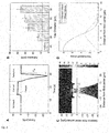
- Figs. 3A to 3D show the adhesion of double re-entrant PDMS fibrils 8, wherein in Fig. 3A one can see a representative force curve of a dry adhesion measurement.
- Fig. 3B shows the pull-off forces for the double re-entrant PDMS fibril 8 arrays as a function of fibril tip diameter D for a 2 mN preload force.
- Figs. 3C and D show FE simulations of (C) the normal stress distribution of a single fibril when stretched 25% - normalized to stress at the base - and (D) the corresponding stress profile at the contact interface. Such relatively equal stress distribution is required for maximum adhesion.
- Adhesion of the fabricated fibrillar surfaces was characterized with pull-off force measurements ( Fig. 3A ) using a smooth hemispherical glass probe (radius of curvature: 4 mm) as the contacting surface at a speed of 25 ⁇ m/s ( fig. 7 ).
- Pull-off forces increased with increasing tip diameter D, when all other fibril 8 dimensions were fixed ( Fig. 3B ), reaching values up to five times higher than a flat control surface for the largest diameter (32 ⁇ m) with a preload force of 2 mN.
- adhesion stress surpassed 100 kPa for the tip diameter 28 ⁇ m and larger.
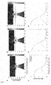
- Figs. 4A to F show the adhesion of double re-entrant PDMS fibrils 8 with different liquids at the contact interface.
- Fig. 4A one can see the adhesion with 5 ⁇ l of water, ethylene glycol or methanol compared to dry adhesion.
- Fig. 4B shows the effect of contact surface hydrophilicity/hydrophobicity on adhesion with methanol at the contact interface and
- Fig. 4C shows representative force curves of both cases.
- FIG. 4D to F show representative force curves for water, ethylene glycol and methanol at the contact interface when using a hydrophilic probe, and corresponding snapshots of real experiments showing the wetting state with added dashed lines for clarity (yellow: dry contact, blue: Cassie state, red: Wenzel state; scale bars: 1 mm).
- the insets of Fig. 4D and E show a positive force as the droplet Laplace pressure is positive, while the inset of Fig. 4F shows a negative force as the liquid collapses to the Wenzel state.
- the approach of integrating recent advances in bioinspired adhesion and wetting research effectively provides a new perspective for robust soft fibrillar adhesive surfaces that can function in real-world applications with possible liquids on surfaces.
- the fibrils retain adhesion after repeated cycles ( Fig. 10 ) and are highly resistant to damage.
- the scalable molding-based fabrication process according to the invention allows future scaled-up manufacturing of such liquid-superrepellent fibrillar adhesives for a wide range of industrial applications in apparel closures, robotics, automotive industry, medical devices, portable electronics, and manufacturing, where there could be oil on contact interfaces.
- the fibrils 8 were designed using CAD software (Inventor Professional 2016, Autodesk Inc., San Rafael, CA, USA), converted to laser writing files (DeScribe, Nanoscribe GmbH, Düsseldorf, Germany) and printed using a laser 3D printer based on two-photon polymerization (Photonic Professional GT, Nanoscribe GmbH, Düsseldorf, Germany).
- the masters 10 were printed on 25 mm ⁇ 25 mm ⁇ 0.7 mm (thickness) indium tin oxide (ITO) coated glass substrates using the commercial IP-S photoresist (Nanoscribe GmbH, Düsseldorf, Germany).
- the ITO coated glass was placed in a closed desiccator next to a droplet of 1,1,1,3,3,3-Hexamethyldisilazan (HMDS, Carl Roth GmbH, Düsseldorf, Germany) and left overnight.
- HMDS 1,1,1,3,3,3-Hexamethyldisilazan
- the master fibril array 12 was developed in propylene glycol monomethyl ether acetate (PGMEA, Sigma-Aldrich Inc., St. Louis, MO, USA) for 30 minutes, followed by a short rinse in isopropyl alcohol (IPA).
- PGMEA propylene glycol monomethyl ether acetate
- IPA isopropyl alcohol
- the fibril master mold 10 was first activated in an oxygen plasma chamber (model: Zepto, Diener electronic GmbH, Ebhausen, Germany) for 3 minutes at 90 Watt, and then fluorosilanized by placing it in a vacuum desiccator together with a glass vial containing 0.1 ml Trichloro(1H,1H,2H,2H-perfluorooctyl)silane (Sigma-Aldrich Inc., St. Louis, MO, USA) for 1 hour, followed by baking it in an oven at 90 °C for 1.5 hours.
- an oxygen plasma chamber model: Zepto, Diener electronic GmbH, Ebhausen, Germany
- fluorosilanized by placing it in a vacuum desiccator together with a glass vial containing 0.1 ml Trichloro(1H,1H,2H,2H-perfluorooctyl)silane (Sigma-Aldrich Inc., St. Louis, MO, USA) for 1 hour, followed by baking it
- the fluorosilanized master substrate 10 was fixed to a larger, 80 mm ⁇ 80 mm ⁇ 1.8 mm, glass plate using a fast curing silicone (Flexitime Correct Flow, Kulzer GmbH, Hanau, Germany), and surrounded by 10 mm high, 50 mm ⁇ 50 mm inner area walls made of Poly(methyl methacrylate) (PMMA) to limit the flow of PDMS during the following molding.
- a fast curing silicone Frlexitime Correct Flow, Kulzer GmbH, Hanau, Germany
- PMMA Poly(methyl methacrylate)
- a softer PDMS mixture 14 (20:1 base monomer to crosslinker ratio) was prepared and poured around the fluorosilanized master substrate 10 and after 15 min of degassing in a vacuum desiccator the PDMS 14 was allowed to flow over the master 10 by tilting the desiccator.
- the negative replica 16 was cured at room temperature for 48 hours, then in oven at 65 °C for 24 hours, and finally peeled off carefully.
- the negative PDMS replica 16 was placed on a glass plate with the cavities facing up and activated in a UV-ozone chamber (model: PSDP-UVT, Novascan Technologies Inc., Boone, IA, USA) for 30 minutes and then fluorosilanized by placing it in a vacuum desiccator together with a glass vial containing 0.1 ml Trichloro(1H,1H,2H,2H-perfluorooctyl)silane (Sigma-Aldrich Inc., St. Louis, MO, USA) for 5 hours, followed by baking in oven at 90 °C for 1.5 hours.
- a UV-ozone chamber model: PSDP-UVT, Novascan Technologies Inc., Boone, IA, USA
- Standard PDMS (10:1 base monomer to crosslinker ratio) was prepared and poured on the fluorosilanized negative replica 16 around the cavity 18 array and limited by silicone walls and after 15 min of degassing in a vacuum desiccator the PDMS was allowed to flow over the negative replica16 and into the cavities 18.
- the positive replica was cured at room temperature for 48 hours, then in oven at 65 °C for 24 hours, and finally peeled off carefully.
- the surface wettability was characterized using the sessile drop method on a commercial contact angle measurement device (model: DSA100, Krüss GmbH, Hamburg, Germany). Advancing and receding contact angles of a ca. 2 ⁇ l droplet were measured three times at three different locations on each sample, for a total of nine measurements per liquid. Slow liquid dosing and aspiration speeds of 0.1 - 0.2 ⁇ l/s were used.
- the custom adhesion setup was built around an inverted optical microscope (model: Axio Observer A1, Carl Zeiss AG, Oberkochen, Germany) connected to a video camera (model: Grasshopper 3, FLIR Systems Inc., Wilsonville, OR, USA) for visualization of the contact interface.
- Adhesion forces were recorded with a sensitive load cell (model: GSO-25, Transducer Techniques LLC, Temecula, CA, USA) mounted on a computer controlled high-precision motorized piezo stage (model: LPS-65 2", Physik Instrumente GmbH & Co. KG, Düsseldorf, Germany) moving in the z-direction with 5 nm positioning resolution.
- Another high-precision motorized piezo stage was used for y-direction.
- Fine adjustments in x- and y-direction are enabled by a manual xy-stage and tilt correction by two goniometers.
- Motion control of the piezo stages and data acquisition were done using custom software running on Ubuntu Linux.
- the load cell was connected to the computer through a signal conditioner (model: BNC-2110, National Instruments, Austin, TX, USA) and a data acquisition board (model: PCIe-6259, National Instruments, Austin, TX, USA).
- a hemispherical smooth glass probe with a 4 mm radius of curvature was glued to the flat end of a holder that was directly connected to the load cell.
- the microfibrillar adhesive patches were placed on a glass slide underneath the probe, which was moved down at 25 ⁇ m/s until the desired preload force was reached.
- the preload was maintained for 10 s, after which the probe was retracted at 25 ⁇ m/s until the glass probe fully detached from the sample.
- Low approach and retraction velocities were employed in order to minimize viscoelastic effects.
- the contact area was visualized by the microscope.
- a 5 ⁇ l drop of liquid was applied onto the sample surface by a micropipette.
- the droplets Since both surfaces were liquid super-repellent, the droplets maintained a highly spherical shape until placed down on a flat PDMS surface. Picking droplets was also demonstrated with the bottom surface attached to a highly curved, concave piece (half pipe) of plexiglass and the top surface accordingly to a convex half cylinder.
- the simulation studies were conducted to analyze stress distributions for contact interfaces and fibril bodies when tensile load is applied.
- FEA finite element analysis
- COMSOL Multiphysics 5.4 COMSOL Inc., Burlington, MA, USA
- the stress distribution at the contact interface was studied following the numerical approach.
- interfacial stress we further studied stress distribution on the fibril body to identify where the maximum stress appears due to the unconventional shape of the fibril.
- the fibril was assumed fixed at the base and fibril top initially attached to a flat rigid surface (probe), while tensile load was applied to the far end of the probe.
- the hyperelastic behavior of the stretched fibril was represented by the Mooney-Rivlin hyperelastic model.
- Figs. 5A - 5E show fibril tip designs (top row) and SEM micrographs of corresponding 3D microprinted rigid half fibrils (bottom row).
- the scale bars are of a size of 10 ⁇ m. These designs were replicated in PDMS and their adhesion evaluated ( Fig. 3B ).
- the fibril tip diameter D is 28 ⁇ m for all measurements.
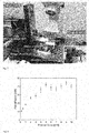
- Fig. 7 is a photograph of a custom built setup used in the adhesion measurements described above with the inset showing a close-up of the load cell and the attached glass probe used as the contacting surface.
- Fig. 8 shows the adhesion dependency on preload, i.e. the adhesion of the PDMS fibrillar adhesive against a smooth hemispherical glass probe (radius of curvature 4 mm) as a function of the applied preload force.
- the fibril tip diameter D was 28 ⁇ m and preload was applied for a duration of 10 seconds.
- Figs. 9A to F show different FE simulations of PDMS fibrils under tensile load, wherein Figs. 9A to C represent cross-sectional views of normal stress heat maps by (A) infinitesimal stretch, (B) 12.5% stretch and (C) 25% stretch.
- Figs. 9D to F show interfacial normalized normal and shear stress profiles by (D) infinitesimal stretch, (E) 12.5% stretch and (F) 25% stretch.
- the stress values are normalized by the normal stress at the fibril base in each case.
- the normal stress trend from infinitesimal stretch to 25% stretch shows that the stress is mostly concentrated on the neck and around the center axis and remains low at the overhang structure.
- both normal and shear stress around the center axis increase by tensile stretch, while remaining low at the edge. This suggests that the overhang structure does not interfere with adhesion performance but rather helps by preventing peeling initiated from the fibril edge.
- Fig. 10 represents the adhesion of the PDMS fibrillar adhesive over 30 cycles of repeated measurements for a fibril cap diameter D of 28 ⁇ m and a preload force of 5 mN.
- the first measurement yields a considerably higher adhesion and then quickly stabilizes.
- the presented values are single measurements carried out sequentially on the same spot.
Landscapes
- Chemical & Material Sciences (AREA)
- Organic Chemistry (AREA)
- Engineering & Computer Science (AREA)
- Chemical Kinetics & Catalysis (AREA)
- Manufacturing & Machinery (AREA)
- Mechanical Engineering (AREA)
- Materials For Medical Uses (AREA)
- Prostheses (AREA)
- Shaping Of Tube Ends By Bending Or Straightening (AREA)
Abstract
Description
- The invention relates to a method of producing a liquid repellent fibrillar dry adhesive material having a plurality of fibrils. Furthermore, the invention relates to a fibrillar dry adhesive material in particular having liquid super-repellency.
- Certain species of insects, arachnids and reptiles, most notably the gecko lizards, have micro- or nanoscale fibril arrays on their footpads that function as high-performance dry adhesives, allowing them to effortlessly climb on diverse surfaces. The remarkable attachment ability is based on van der Waals and capillary forces and the principles of contact splitting and crack trapping. Synthetic mimics of these fibrillar adhesive systems have been actively developed in the past two decades with performance reaching and even surpassing that of geckos on smooth surfaces. Such fibrillar adhesive pads not only provide strong attachment to diverse surfaces but they are also superhydrophobic. Water repellency has been suggested to contribute to self-cleaning of the gecko footpads and their synthetic mimics through the lotus leaf effect, and it likely helps keeping the dry adhesion mechanism functional. Indeed, it has been found that wetting by water dramatically decreases the adhesion of gecko footpads to substrates. Similar reduction in performance has been reported for artificial bio-inspired adhesives under water.
- In the case of low surface tension liquids, such as oils, wetting becomes a major concern if the liquid spreads easily at the interface and between the fibrils. Even though carefully controlled, thin layers of viscous oil (0.1 - 2.1 µm thick) applied on the fibril tips of artificial dry adhesives can enhance adhesion on both smooth and rough surfaces, larger volumes of liquids (0.1 - 0.4 µl) at the solid-solid interface have been shown to drop adhesion to a fraction compared to dry conditions. For overall adhesion performance in various wetting conditions, it would be advantageous to displace (push away) liquid from the contact interface and make a dry contact. Preferably all liquids, regardless of their surface tension, should remain in the Cassie state (i.e. suspended on top of the fibrils), even during contact with the target surface. The transition barrier to the Wenzel state (i.e. fully wetting the substrate and fibrils) should also be sufficiently high to provide robust liquid repellency since the adhesion would drop drastically in the Wenzel state.
- Combining high adhesion and liquid repellency on the same fibrillar surface is challenging as the two properties have fundamentally opposing requirements for solid fraction - it should be large for adhesion and small for liquid repellency. Furthermore, high liquid repellency has been traditionally achieved by a combination of surface chemistry and roughness modification, an approach which is incompatible with the goal of high adhesion. For example, sprayable coatings can be extremely effective at turning a surface super-repellent to all liquids but they rely on ultralow surface energy and hierarchical micro- and nanoscale roughness, which are both detrimental to dry adhesion.
- Another prominent avenue for achieving repellency towards low surface tension liquids is based on arrays of microscale features with re-entrant geometry, inspired by the skin of springtails. In recent years, this approach has been taken further by the introduction of double re-entrant structures, which can repel all liquids regardless of surface chemistry. However, to date, the fabrication techniques only allow the use of rigid materials, which are not suitable for dry adhesives.
- Bio-inspired elastomer fibrillar surfaces could have tremendous potential as reversible dry adhesives, but their performance is sensitive to the presence of liquids at the contact interface. Like their models in nature, many artificial mimics can effectively repel water, but fail when low surface tension liquids are introduced at the contact interface.
- Thus, it is an object of the invention to provide a method for producing a fibrillar adhesive as well as a fibrillar adhesive material, which can repel liquids, especially liquids with low surface tension, and which can still adhere strongly at the contact interface.
- This object is satisfied by the invention according to the subject matter of the independent claims.
- In particular, a method of producing a liquid repellent fibrillar dry adhesive material having a plurality of fibrils is made available. The produced fibrils have a tip and a body and the tip has a larger outer dimension than the body. The method according to the invention comprises the following sequence of steps:
- a) providing a negative mold having a surface and comprising cavities having a shape corresponding to an outer shape of the fibrils to be produced, wherein the mold is formed of a first material;
- b1) activating said surface and said cavities of said mold and then passivating the first material by providing a silane or another chemical treatment to the activated first material; or
- b2) providing a polymer coating to said surface and said cavities;
- c) applying vacuum to remove air out of the cavities;
- d) filling the cavities with a second material having a Young's modulus selected in the range of 10 kPa to 600 MPa;
- e) curing the second material to produce at least the fibrils optionally keeping some of the second material as a backing substrate to hold the fibrils together; and optionally
- f) demolding the first material from the second material to obtain said fibrils at said second material.
- In other words, first a negative mold is provided, which comprises cavities having an inner shape which corresponds with the outer shape of the fibrils to be produced. Said shape is preferably mushroom shaped, in particular double re-entrant shaped, i. e. with an undercut remote from a top surface of the tip of the fibril. As mentioned above, such double re-entrant shapes have shown to achieve high repellency towards liquids regardless of the surface chemistry, which is one of the goals to be achieved by the invention. Conventionally, extreme liquid repellency is achieved by a combination of surface roughness and surface chemistry (i.e. low surface energy treatment). Double re-entrant fibrils are the only known method for making a surface liquid superrepellent regardless of the surface chemistry. Furthermore, adding double re-entrant edges to the fibrils also does not change the 2D shape of the top surface of the tip (looking from the top) or the smoothness of the top surface, which is crucial for the material to have high adhesion..
- The body can be formed in several shapes, such as cubic, pyramidal, spherical, cylindrical, conic, cuboidal, triangular or hexagonal.
- One method to prepare the mold for the further processing steps comprises the steps of activating the surface and the cavities of the mold and then passivating said surface and said cavities by providing a silane or other chemical treatment at the activated first material.
- A common method for passivating a material may be the so-called fluorosilanization, where the surface of a material is covered with organofunctional alkoxysilane molecules. This helps to reduce the adherence of at least the surface and the cavities, i. e. to reduce the surface energy of the mold in order to be able to later remove the produced fibrils from the mold.
- Another way to passivate the mold is to coat the surface and the cavities with an inert polymer, such as Parylene C, which can act as a non-stick coating..
- In a next step vacuum is applied in order to remove air especially out of the cavities regardless of which method was chosen earlier to passivate the mold (surface and cavities). It has shown that when cavities with a double re-entrant shape are supposed to be filled with a (liquid) material, air can be trapped mostly in the edges of the undercut. Such a trapping of air would worsen the final result of the fibrils, i. e. alter the shape of the produced fibrils. Therefore, vacuum is applied to remove the air to later be able to fill the whole cavity with a second (liquid) material.
- After applying the vacuum the cavities are filled with a second material having a Young's modulus selected in the range of 10 kPa to 600 MPa, i. e. with a comparatively soft material in comparison to the fibrils having complex structures known from the state of the art that are made from rigid material.
- As mentioned above, the applied vacuum will support in filling the cavities completely since the material can easily flow into the cavities, e. g. because of gravity, without being hindered by trapped air bubbles, which could keep the material from entering parts of the cavity. It is possible that the second material is the same material as the first material, i. e. the material of the negative mold, but it does not necessarily have to be. Another possibility would be that the first and the second material only comprise the same base material but are mixed in a different mixing ratio with a cross-linking agent. In a most preferred embodiment the first material, i. e. the mold material, has a Young's modulus, which is 2 to 10 times smaller than the one from the second material. That is to say that the negative mold is substantially softer than the produced fibrils. This can make the further step of demolding way easier, especially when the final replica comprises fibrils having the complex double re-entrant shape.
- The second material is then fully cured, which can take about an hour, when the material is heated appropriately or even up to several days if the material is kept at a cooler environment. A common method is to heat the mold with the filled cavities in order to reduce the curing time. The exact curing time depends mostly on the chosen material as well as on the ambient temperature and can thus be chosen appropriately. Furthermore, the curing temperature can be chosen in accordance with the desired softness of the material since, for example, for elastomers higher curing temperatures lead to harder cured materials (i. e. higher Young's modulus) and vice versa. Thus, for soft materials often lower curing temperatures and longer curing times are chosen in order to end up with a material of the desired Young's modulus.
- After curing the second material, the fibrils have basically already been produced. The only step left is to remove the mold from the produced replica of the fibrils. Since the material of the fibrils is a soft material, this can be done by using appropriate tweezers. With said tweezers the final replica of the fibrils can be grabbed and peeled off the mold manually. This is possible since the surface of the mold has been prepared such that it is non-sticky before (activating/passivating process) enabling the negative mold to be demolded from the replica without destroying the delicate structures of the re-entrant shaped fibrils.
- According to a first embodiment of the invention the step of activating comprises either the provision of oxygen at the first material and then applying UV radiation at the oxygen atoms to produce ozone; or the provision of an oxygen plasma at the first material. Said process of activation leaves the surface hydroxyl (-OH) terminated and thus allows later, for example, fluorosilane to covalently bind to it during the step of passivating the material.
- Because of the double re-entrant shape of the produced fibrils particular care has to be taken to coat the cavities such that every edge and corner, especially of the undercut, is reached in order to reach a continuous layer of coating that subsequently permits the separation of the fibrils from the negative mold. A similar effect to the provision of a coating of step b2 can be achieved by the activation and passivation carried out in step b1.
- By providing method steps that activate and then passivate the surface topology of the negative mold, the whole surface of the negative mold and the cavities present therein can be made non-sticky independently of the shape of the cavities.
- In this connection a non-sticky coating means that the fibrils are separated from the negative mold by a layer of inert molecules in such a way that the fibrils once cured can be separated from the negative mold without remaining attached thereto and without damaging the fibrils.
- According to another embodiment the method further comprises the steps of:
- a) producing a master having a surface and comprising patterns of the plurality of fibrils, for example, by using an additive manufacturing technique, such as two-photon lithography or 3D printing;
- b1) activating said surface and said patterns of said master and then passivating the master material by providing a silane or other chemical treatment to the activated master material;
- b2) coating said surface and said patterns with a polymer coating;
- c) covering the prepared patterns of the plurality of fibrils with the first material;
- d) curing the first material;
- e) removing the master to produce the negative mold.
- Thus steps c to e are carried out respectively after one of steps b1 and b2.
- Thus, it can be seen that the negative mold can be produced in a similar way as the fibrils by using a "negative" model of the fibrils, which in this case would be the master. The master comprises the patterns of the fibrils to be produced (thus enabling the formation of the "negative shapes" of the cavities of the negative mold).
- The surface of the master can then either be activated and passivated or coated with a polymer coating in order to prepare the surface for the next steps of the production, i. e. the covering of the patterns with a first material, which may be a soft material, in particular the same material as the second soft material used to produce the fibrils. Thus, it can be preferred to produce the negative mold of a soft material as well in order to be able to handle the delicate fibrils better.
- In this connection it should be noted that also the patterns can be coated with a "non-sticky coating" as mentioned in the foregoing in order to be able to separate the patterns of fibrils from the negative mold by a layer of inert molecules in such a way that the negative mold once cured can be separated from the patterns without remaining attached thereto and without damaging the negative mold.
- Since the fibrils to be produced can comprise a rather complicated shape, additive manufacturing techniques such as 3D printing are needed to produce the master, and especially the patterns on the master, with high accuracy. It may also be possible to produce the master with conventional microfabrication techniques or even with a bottom-up self assembly process.
- It is preferred that the step of preparing the patterns of the plurality of fibrils comprises either the provision of oxygen at the master material and then applying UV radiation at the oxygen atoms to produce ozone; or the provision of an oxygen plasma at the master material. As already mentioned above, this can be done as a first step in order to provide a, so to say, non-sticky coating, to the surface of the master, even on the surface of the undercuts of the patterns.
- According to another embodiment at least one of the first material and the second material has a Young's modulus selected in the range of 10 kPA to 5000 MPa, in particular in the range of 10 kPa to 600 MPa, especially in the range of 10 kPa to 50 MPa, preferably in the range of 100 kPA to 15 MPa, in particular in the range of 100 kPA to 5 MPa. Thus, it may be possible that the first and the second material are both soft materials. It has shown that such a choice of soft materials of both the first and the second material can be advantageous when double re-entrant shaped fibrils of a soft material are supposed to be produced. Preferred materials can be polymers, such as elastomers (PDMS or polyurethane). On the other hand, it could also be possible that, for example, the mold is produced from a rigid material by using commonly known fabrication techniques, which may be easier and cheaper.
- According to another aspect of the invention a fibrillar dry adhesive material is provided, which is in particular made and/or obtainable by a method according to the invention. The fibrillar dry adhesive material comprises a plurality of fibrils, each fibril having a double re-entrant fibril tip geometry. Furthermore, each fibril is made of a soft material, wherein the soft material has a Young's modulus selected in the range of 10 kPa to 5000 MPa. Thus, double re-entrant shaped fibrils are given, which are made of a soft material. This way, the fibrils are fully soft and the material comprises a liquid super-repellent surface, which is mechanically not brittle, highly robust against physical contact, highly deformable, flexible and stretchable. State-of-the-art liquid super-repellent surfaces made of rigid materials are very susceptible to mechanical damage/contact. Some recent studies use flexible backing and rigid microstructures to make them bendable, but the structures themselves are still highly vulnerable to mechanical contact and damage. By being entirely soft, the elastomeric structures according to the invention address a fundamental, long-standing challenge for liquid super-repellent surfaces, which is the lack of mechanical durability.
In view of the foregoing a novel approach is proposed for strong adhesion to dry and wet surfaces. Microfibrillar adhesive films are made available that are composed of elastomeric microfibers decorated with tips terminating in a re-entrant geometry. Such fibril shape allows simultaneously strong dry adhesion and extreme liquid repellency. Specifically, the surface enables dry adhesion in the presence of liquids, including oils and other low surface tension liquids. Additionally, the same microfibrillar adhesive presents a fully soft, flexible, stretchable, bendable, twistable and durable liquid superrrepellent surface. The advantages described in connection with liquid repellency likewise hold true for the adhesive properties. - In this connection it should be noted that the double re-entrant geometry of the tip of the fibrils avoids the liquids from flowing down the fibrils and coming into contact with the base of the fibrils which would prevent these from adhering to the surface to which they should attach. This is because the fibrils would no longer establish intimate contact with the surface as liquid would infiltrate the space between the tips and the surface, where even a single monolayer of liquid interferes with the short-range intermolecular attractive forces between the fibrils and the surface..
- According to an embodiment of the invention the material further comprises a backing substrate on which the fibrils are arranged. The backing substrate can either be made of the same material as the fibrils or a different material. Furthermore, the backing substrate additionally can be connected to a payload. The main purpose of the packing substrate is to hold several fibrils together, in particular arranged in arrays, in order to produce a material of the above described properties.
- According to another embodiment the soft material has a Young's modulus selected in the range of 100 kPA to 50 MPa, especially in the range of 100 kPa to 15 MPa, preferably in the range of 100 kPA to 5 MPa.
- It is preferred that the soft material is selected from the group of members consisting of organic, inorganic, polymers, rubbers, biomaterials, composites, foams, fabric materials, particle materials, fibrous materials, or combinations of the foregoing. In this connection it is noted that the soft material is preferably an elastomer, such as PDMS or a polyurethane elastomer.
- It is another embodiment of the invention that the fibrils comprise a fibril body and a tip extending over edges of the fibril body that terminate with the re-entrant geometry, wherein a top part of the tip comprises a flat, convex, concave, wavy, undulating, zig-zag, smooth or rough geometry. Therefore, the fibrils can be formed mushroom shaped and the most preferred double re-entrant geometry of the tip of the fibril can comprise more than one bend downward and then toward the fibril body away from the top surface of the tip of the fibril.
- According to another embodiment the tip is an integral part of the fibril body or wherein the tip is added separately to the fibril body. In the case of a separate adding of the fibril tip to the body it is noted that the tip can be connected to the body by inking or gluing them together. Thus, for the example of gluing, the tip can be dipped into a third material, e. g. an uncured elastomer, polymer or adhesive, and then placed on the body. In a further step, the third material would have to cure in order to permanently hold the tip and the body together. During the inking process, the third material itself typically forms the tip. After dipping the body, the tip shape is determined by whatever the inked body is pressed against (usually a flat, smooth surface) and the dynamics of "pressing". For example, if the body is already a mushroom-like "T-shape", then inking and pressing (using suitable force and speed) against a flat surface might make the ink material spread slightly over the edges of the T to form a second undercut, or double re-entrant geometry. Alternatively the tip and the body are produced together out of the same material such that they form one integral fibril.
- According to a different embodiment the ratio of the diameter of the tip to the diameter of the body lies in the range of 1 to 100, preferably in the range of 1 to 50, most preferably in the range of 1 to 10, especially in the range of 1 to 5. Thus, the fibril body is notably thinner than the fibril tip.
- In this connection it is noted that a typical value for the diameter of the tip lies within a range of 10nm to 1mm, preferably 0.1µm to 100µm. Typical values for the width and length of the re-entrant parts of the tip, on the other hand, lie within a range of 1nm to 1mm, preferably 10nm and 100µm.
- It is preferred that a density distribution of the plurality of fibrils, preferably on the backing substrate, is defined by a ratio of a surface area of voids present between the individual fibrils to a surface area of the fibrils, with the ratio lying in the range of 0.01:100 to 100:0.01, preferably in the range of 1:100 to 100:1. It has been found that when less voids per surface area are present, the better the adhesion gets. This, obviously, only holds down to a certain limit. A flat surface with no voids, for example, would worsen the adhesion since the actual/effective contact area would in practice be smaller with most real-world surfaces, due to worse conformation. When more voids are present, on the other hand, the liquid repellency is improved. Thus, an appropriate ratio has to be chosen in order to achieve both a good adhesion as well as a good liquid repellency.
- According to another embodiment of the invention the fibrils are arranged in regular or irregular arrays, in particular on the backing substrate. Forming regularly spaced arrays means that the ratio of the surface area of the voids to the surface area of the fibrils can be predefined in a simple manner. If, on the other hand, irregularly shaped arrays are selected, then the backing substrate can, for example, be used to connect the regions where a non-uniform distribution of the arrays may be beneficial. Thus, the arrangement of the fibrils can be chosen according to the application of the material.
- It is another embodiment of the invention that the fibrils and the backing substrate are formed integrally or wherein the fibrils and the backing substrate are formed separately and are connected to one another. Thus, the backing substrate and the fibrils may either be formed of the same material or of different materials. It can be chosen according to the application of the material which embodiment is preferred. In the case of independent fibrils and backing substrates the same glueing/inking techniques as explained in connection with the fibril tips and bodies can be chosen to connect the two parts.
- It is also possible that the backing substrate is a material selected from the group of members consisting of organic, inorganic, metals, alloys, ceramics, glass, polymers, rubbers, biomaterials, composites, foams, fabric materials, particle materials, fibrous materials, hydrogels and combinations of the aforementioned. In this connection it is noted that the backing substrate can also be made out of one of the above mentioned materials and then coated with an additional layer. Said layer may again be a material selected from the group of members consisting of the above mentioned examples. The thickness of said layer may lie within a range of 1 nm to 1mm.
- According to another embodiment of the invention a width and a breadth of the backing substrate are equal to or bigger than 10µm and a thickness of the backing substrate lies in the range of 0.01µm to 1cm. Thus, there is basically no upper limit for the width and the breadth of the backing substrate, meaning that it can also be possible to produce sheets of fibrillar dry adhesive material, which eventually can later be placed on a payload. Said payload would make the overall thickness of the substrate substantially bigger, which has no impact on the adhesion and liquid repellency properties of the fibrils.
- It is preferred that the fibrils and/or the backing substrate further comprise a filler material selected from the group of members consisting of organics, inorganics, metals, alloys, ceramics, glass, polymers, rubbers, biomaterials, hydrogels, liquid materials, phase changing materials, composites, foams, fabric materials, particle materials, fibrous materials, micro- and nanoparticles and combinations of the foregoing. An example for the use of filler materials could be magnetic microparticles, which enable the material to be movable, or metal particles, which can make the material switchable or electrically conductive so that it could e.g. be used as part of a sensor. It could also be possible to introduce a type of functionalized material in order to give the backing substrate, for example, a further function apart from holding the fibrils together.
- It is another aspect of the invention to use the fibrillar dry adhesive material according to invention, in particular made and/or obtainable by a method according invention, for wearable devices, electronics, apparel, apparel closures, robotics, automotive coatings, portable electronics or other devices, space technology, manufacturing technologies with oily contact interfaces, liquid repellant devices, liquid repellants in devices, food packaging, surgical tools and other medical devices, underwater marine vessels and manipulation of liquid droplets including picking droplets, pinning droplets, releasing droplets and transporting droplets. Thus, it can be seen that the liquid repellent fibrillar dry adhesive material can be used in several different applications, meaning that it can have a tremendous potential.
- Further embodiments of the invention are described in the following description of the Figures. The invention will be explained in the following in detail by means of embodiments and with reference to the drawings in which is shown:
- Figs. 1A to E:
- The fabrication steps of soft elastomeric double re-entrant fibril arrays according to the invention;
- Figs. 2A to D:
- an illustration of the liquid repellency of double re-entrant PDMS microfibrils;
- Figs. 3A to D:
- an illustrastion of the adhesion of double re-entrant PDMS fibrils;
- Figs. 4A to F:
- results of the adhesion of double re-entrant PDMS fibrils with different liquids at the contact interface;
- Figs. 5A to E:
- different fibril cap diameters for adhesion studies;
- Fig. 6:
- the fibrillar adhesive wettability dependency on pitch;
- Fig.7:
- a measurement setup;
- Fig. 8:
- results for the adhesion dependency on a preload;
- Fig. 9:
- results of FE simulations of PDMS fibrils under tensile load; and
- Fig. 10:
- the adhesion over repeated cycles.
-
Fig. 1A shows schematically the different steps of the method according to the invention beginning with the production of amaster 10. In a first step the rigid master is 3D-printed using two-photon lithography such that the master comprisespatterns 12 of a plurality of fibrils, which are supposed to be produced, i. e. thepatterns 12 of the plurality of fibrils comprise the same outer shape as the producedfibrils 8 at the end of the manufacturing process, i.e. a double re-entrant shape. Said shape will be explained in detail in connection withFigs. 1B to E . For the production of themaster 10 commonly known (rigid) materials, which can be used for additive manufacturing techniques, can be chosen. - In a second step the
master 10 including itspatterns 12 are first covered with a non-stick coating (not shown) and then with a firstsoft material 14. Thus thepatterns 12 are replicated with the firstsoft material 14 in order to produce anegative mold 16 comprisingcavities 18 with an inner shape corresponding to the outer shape of thepatterns 12, i. e. the double re-entrant shape of the fibrils to be produced. The firstsoft material 14 usually comprises a Young's modulus in the range of 10kPa to 5 MPa. Also higher values are possible as long as they still lie within a range where the material can be regarded as "soft". - The "non-stick coating" is supposed to reduce the surface energy of the
cavities 18 in order to simplify the further step of demolding themaster 10 from the first soft material 14 (the mold 16). In commonly known methods for manufacturing double re-entrant shapes out of rigid materials a non-stick coating is not necessary since they can be produced with additive manufacturing processes. Here it is the case that a double re-entrant shape is supposed to be produced out of soft materials, which is why anegative mold 16 is needed. Therefore, in a first embodiment of the invention, the surface of the master is first activated by providing oxygen molecules to the master. Said oxygen molecules are then illuminated with UV radiation which causes the oxygen to react with, for example, the carbon dioxide in the air to produce ozone. These ozone molecules are able to reach every edge and corner of the patterns to react and activate the surface. In a further step, passivation is initiated by providing a silane, preferably fluorosilane, or another chemical treatment to the activated surface, which can react with the activated surface in order to give it a sensation of a "non-sticky coating", i. e. to help in a further step of demolding the master from the first material. - Another possibility would be to provide an oxygen plasma to the master surface to activate the surface before passivating it with fluorosilane or another chemical treatment.
- In another embodiment of the invention, the surface and the patterns of the master are simply covered with a polymer coating. When using this method a provision of UV radiation is not necessary.
- In a further step, regardless of which "coating"-method has been chosen, before the
master 10 is demolded, the firstsoft material 14 is cured since thematerial 14 is usually in a liquid phase when it is applied to themaster 10. Depending on the exact material used for the firstsoft material 14 and depending on the ambient temperature said curing can be done within 10 minutes, when the temperature is raised to 150°C, within an hour, when the temperature is raised up to 90°C, or can even take up to 48 hours when the temperature is kept at room temperature (example of PDMS with a standard 10:1 monomer to crosslinker ratio). For softer formulations like, for example, a 20:1 ratio room temperature curing takes even longer. - In order to demold the
master 10, without destroying it, from thefirst material 14 it can be mechanically peeled off by using conventional tweezers. Since the surface of themaster 10 has been prepared with the activation and passivation steps or with the polymer coating, as described before, it can be peeled off rather easily from thefirst material 14 without destroying the delicate structures of thecavities 18 or thepatterns 12. Other demolding techniques like chemical dissolving may generally be possible depending on the used materials but are nevertheless infeasible since they would destroy the master and make it not reusable. - After the
mold 16 is completely separated from the master (which is only possible because of the previous "coating"-steps), first the surface of themold 16, and especially thecavities 18, are coated by using one of the coating techniques described above (activating/passivating or polymer coating). Then, vacuum is applied to thecavities 18 in order to remove air (not shown) from thecavities 18. This will help in the next step where thecavities 18 are filled with a secondsoft material 20. The secondsoft material 20 can be the same material as the firstsoft material 14. In general it is also possible to use different materials, but it has been shown that soft materials for both the first and thesecond material Fig. 1A , for example, the first and secondsoft materials first material 14 versus 10:1 for the second material 20). - In order to fill the
cavities 18 completely, it might be necessary to tilt thenegative mold 16 to a certain degree in order to let thesecond material 20 flow into thecavities 18, especially also in the undercutparts 24 of the cavities 18 (see e. g.Fig. 1B ). Usually, as thesecond material 20 enters thecavities 18, from which the air has been removed, gravity and hydrostatic pressure will ensure that thecavity 18 is filled completely with thesecond material 20 even if themold 16 is not tilted that much or not tilted at all. - One possibility would also be to provide the
second material 20 at themold 16 without the second material initially coming into contact with thecavities 18, before applying the vacuum to themold 16. Then, after the vacuum has been applied, themold 16 is moved, in particular tilted, relative to the second material such that thesecond material 20 flows into and completely fills the degassedcavities 18 to form the fibrils within thecavities 18. - In this connection it is noted that it is either possible to only fill the
cavities 18 with the secondsoft material 20 or to cover thewhole mold 16 with the material 20 in order to also produce abacking substrate 22, which is supposed to hold the array offibrils 8 together. Most common techniques use the latter and additionally provide abacking substrate 22. Saidbacking substrate 22 can have a thickness of about 0.5 to 1mm or even up to 10 cm. For certain applications it is also possible to attach thebacking substrate 22 to a payload (not shown) which is generally not limited in size and dimensions. - The next step comprises curing the second
soft material 20 to finally produce thefibrils 8. Optionally some of the curedsecond material 20 can be kept in order to provide saidbacking substrate 22. In some embodiments it is also possible to remove the parts of the curedbacking substrate 22 with a razor blade or the like (not shown) in order to only keep thefibrils 8 at the end. Furthermore, it could also be possible to first add thebacking substrate 22 and then add a third material, which could act as a "new" backing substrate. - Lastly the first
soft material 14 is demolded from the secondsoft material 20 to only end up with the produced fibrils 8 (and optionally the backing substrate 22). - Thus, in summary, for the elastomeric fibrillar surface fabrication (
Fig. 1A ), first a two-photon polymerization method was used to 3D-print themaster 10 fibril array (patterns 12) on a glass substrate. Themaster 10 was then fluorosilanized to allow subsequent demolding, and PDMS (first soft material 14) was then cast and cured on thefibril array 12. The negative replica (negative mold 16) was peeled off and fluorosilanized and thesubsequent molding 16 yielded a PDMS replica of theoriginal master 10. A softer PDMS composition (20:1 monomer to crosslinker ratio) for the negative replica was employed to facilitate demolding of the final replica, for which standard PDMS (second soft material 20) was used (10:1 monomer to crosslinker ratio). The final replicas were characterized as prepared without any further processing. - The
fibrils 8, which could be produced with the above disclosed method are shown inFigs. 1B to 1E . One can immediately see that thefibrils 8 are of a double re-entrant shape, where eachfibril 8 comprises afibril body 26 and afibril tip 28. - The
fibril 8 dimensions (Fig. 1B ) of the fibrils 8shown in theFigs. 1C to 1E were fixed as base diameter B = 30 µm, height H = 40 µm, neck diameter d = 10 µm, overhang height h = 5 µm and overhang thickness t = 3 µm. The tip diameter D was varied for the adhesion studies explained later in connection withFig. 5 . The overhang dimensions could easily be reproduced in 3D-printing (Fig. 1C ) and were set large enough to facilitate replication in PDMS (Fig. 1D ). Fibril pitch for the replicated arrays (Fig. 1E ) was chosen as 60 µm to maximize their liquid repellency (Fig. 6 ). -
Figs. 2A to 2D show the liquid repellency of thefibrils 8 produced with the method according to the invention. InFig. 2A one can see a liquid on top of the fibrils supported by vertical components of surface tension.Fig. 2B shows the advancing (blue) and receding (red) contact angles of perfluorohexane (γ = 11.91 mN/m), methanol (γ = 22.7 mN/m), dipropylene glycol (γ = 33.90 mN/m), ethylene glycol (γ = 47.7 mN/m) and water (γ = 72.8 mN/m) on the PDMS fibril array. The inset shows a droplet of perfluorohexane in the Cassie state on the PDMS fibril array (scale bar: 200 µm).Fig. 2C shows a droplet of methanol on a bent PDMS fibril array (scale bar: 2 mm) andFig. 2D shows a schematic and corresponding real experiment snapshots of picking up a droplet of methanol from a concave fluorosilanized PDMS doublere-entrant fibril 8 surface (bottom) using an identical non-silanized convex surface (top), facilitated by the difference in surface energies. - To achieve reliable liquid repellency, particularly for ultralow surface tension liquids, the
fibril 8 tip diameter D and center-to-center distance in the array were chosen in a way that favors robustness of the Cassie state rather than simply maximizing advancing and receding contact angles by decreasing the solid fraction (the fraction of the solid surface in contact with liquid). In practice this meant inclining towards a larger fibril tip diameter D and smaller center-to-center distance. This tradeoff is reasonable because the increased contact area also leads to higher dry adhesion. It was found that forfibrils 8 with a tip diameter D of 28 µm, reducing the center-to-center distance to 60 µm was required for keeping all the tested liquids in the Cassie state, suspended by the vertical components of surface tension (Fig. 2A ). Liquid repellency of the double re-entrant PDMS fibrils was characterized using contact angle measurements. Advancing and receding contact angles were determined for a variety of liquids covering surface tensions in the range of 11.91 - 72.80 mN/m (Fig. 2B ). Perfluorohexane was included in the test liquids as a representative fluorinated organic solvent, which typically wets most surfaces completely due to its ultralow surface tension (11.91 mN/m). Even perfluorohexane remained in the Cassie state on the double re-entrant soft fibril array (Fig. 2B , inset). Due to the high robustness of the Cassie state, the elastic surface could be bent to a curve and still repelled low surface tension liquids, such as methanol (Fig. 2C ), even allowing droplet pick-and-place manipulation of various liquids including methanol (Fig. 2D ). -
Figs. 3A to 3D show the adhesion of doublere-entrant PDMS fibrils 8, wherein inFig. 3A one can see a representative force curve of a dry adhesion measurement.Fig. 3B shows the pull-off forces for the doublere-entrant PDMS fibril 8 arrays as a function of fibril tip diameter D for a 2 mN preload force.Figs. 3C and D show FE simulations of (C) the normal stress distribution of a single fibril when stretched 25% - normalized to stress at the base - and (D) the corresponding stress profile at the contact interface. Such relatively equal stress distribution is required for maximum adhesion. - Adhesion of the fabricated fibrillar surfaces was characterized with pull-off force measurements (
Fig. 3A ) using a smooth hemispherical glass probe (radius of curvature: 4 mm) as the contacting surface at a speed of 25 µm/s (fig. 7 ). Pull-off forces increased with increasing tip diameter D, when allother fibril 8 dimensions were fixed (Fig. 3B ), reaching values up to five times higher than a flat control surface for the largest diameter (32 µm) with a preload force of 2 mN. Considering the projected contact area at the moment of maximum pull-off force, adhesion stress surpassed 100 kPa for thetip diameter 28 µm and larger. The well-known dependence of adhesion on the preload force was also observed (Fig. 8 ). Finite element (FE) simulations showed that the stress in thefibrils 8 is concentrated around the fibril tip center and neck (Fig. 3C ), while the double re-entrant overhang remains almost free of stress (Fig. 3D ). The FE simulations (Fig. 9 ) and our experiments confirm that adding a double re-entrant overhang to thefibrils 8 does not interfere with their adhesion performance with the selected fibril material and geometries, but may actually help preventing cracks initiated near the fibril edges from propagating and leading to adhesion failure, which is consistent with recent modelling of the T-shaped fibrils. -
Figs. 4A to F show the adhesion of doublere-entrant PDMS fibrils 8 with different liquids at the contact interface. InFig. 4A one can see the adhesion with 5 µl of water, ethylene glycol or methanol compared to dry adhesion.Fig. 4B shows the effect of contact surface hydrophilicity/hydrophobicity on adhesion with methanol at the contact interface andFig. 4C shows representative force curves of both cases.Figs. 4D to F show representative force curves for water, ethylene glycol and methanol at the contact interface when using a hydrophilic probe, and corresponding snapshots of real experiments showing the wetting state with added dashed lines for clarity (yellow: dry contact, blue: Cassie state, red: Wenzel state; scale bars: 1 mm). The insets ofFig. 4D and E show a positive force as the droplet Laplace pressure is positive, while the inset ofFig. 4F shows a negative force as the liquid collapses to the Wenzel state. - To investigate the advantages of liquid superrepellency for bioinspired dry adhesives in realistic wetting conditions, the adhesion of the double
re-entrant fibrils 8 with 5 µl droplets of different test liquids (water, ethylene glycol and methanol) at the contact interface to adhesion in dry condition was compared. The results show that keeping liquid in the Cassie state enables direct dry contact between the fibril and the contact surface so that short-range van der Waals forces dominate and dry adhesion performance is almost completely retained. On the other hand, collapsing to the Wenzel state greatly reduced short-range forces and the remaining weak long-range capillary forces resulted in significantly reduced adhesion (Fig. 4A ). It is noted that if liquid was fully pushed away from the contact interface (e.g. in the case for water), the adhesion was similar to the dry case. If the liquid was partially pushed away (e.g. in the case for ethylene glycol) the adhesion was slightly reduced. Finally, if the liquid was not pushed away at all (e.g. in the case for methanol) and collapsed to the Wenzel state and the adhesion was significantly reduced. For low surface tension liquids, such as methanol, a hydrophobic contacting surface (static contact angle 103.7°) enables partially displacing it, thus preventing a collapse to the Wenzel state and therefore retaining the adhesion performance (Figs. 4B and 4C ). With a hydrophilic contact surface (static contact angle 45.6°), the representative force curves for water, ethylene glycol and methanol illustrate the transition from strong short-range forces facilitated by the Cassie state to weak capillary forces due to the Wenzel state (Figs. 4D - 4F ). Liquid displacement ability of the fibrillar adhesive during contact depends on hydrophilicity/hydrophobicity of the contacting surface (Fig. 4G ), which therefore significantly affects adhesion performance. - The approach of integrating recent advances in bioinspired adhesion and wetting research effectively provides a new perspective for robust soft fibrillar adhesive surfaces that can function in real-world applications with possible liquids on surfaces. The fibrils retain adhesion after repeated cycles (
Fig. 10 ) and are highly resistant to damage. The scalable molding-based fabrication process according to the invention allows future scaled-up manufacturing of such liquid-superrepellent fibrillar adhesives for a wide range of industrial applications in apparel closures, robotics, automotive industry, medical devices, portable electronics, and manufacturing, where there could be oil on contact interfaces. - In the next section it is explained which materials and apparatuses were used for the experiments described above, where
fibrils 8 were produced with a method according to the invention. - The
fibrils 8 were designed using CAD software (Inventor Professional 2016, Autodesk Inc., San Rafael, CA, USA), converted to laser writing files (DeScribe, Nanoscribe GmbH, Karlsruhe, Germany) and printed using a laser 3D printer based on two-photon polymerization (Photonic Professional GT, Nanoscribe GmbH, Karlsruhe, Germany). Themasters 10 were printed on 25 mm × 25 mm × 0.7 mm (thickness) indium tin oxide (ITO) coated glass substrates using the commercial IP-S photoresist (Nanoscribe GmbH, Karlsruhe, Germany). In order to enhance the adhesion of the photoresist to the substrate for molding purposes, the ITO coated glass was placed in a closed desiccator next to a droplet of 1,1,1,3,3,3-Hexamethyldisilazan (HMDS, Carl Roth GmbH, Karlsruhe, Germany) and left overnight. After exposure in the 3D laser printer, themaster fibril array 12 was developed in propylene glycol monomethyl ether acetate (PGMEA, Sigma-Aldrich Inc., St. Louis, MO, USA) for 30 minutes, followed by a short rinse in isopropyl alcohol (IPA). - The
fibril master mold 10 was first activated in an oxygen plasma chamber (model: Zepto, Diener electronic GmbH, Ebhausen, Germany) for 3 minutes at 90 Watt, and then fluorosilanized by placing it in a vacuum desiccator together with a glass vial containing 0.1 ml Trichloro(1H,1H,2H,2H-perfluorooctyl)silane (Sigma-Aldrich Inc., St. Louis, MO, USA) for 1 hour, followed by baking it in an oven at 90 °C for 1.5 hours. Thefluorosilanized master substrate 10 was fixed to a larger, 80 mm × 80 mm × 1.8 mm, glass plate using a fast curing silicone (Flexitime Correct Flow, Kulzer GmbH, Hanau, Germany), and surrounded by 10 mm high, 50 mm × 50 mm inner area walls made of Poly(methyl methacrylate) (PMMA) to limit the flow of PDMS during the following molding. To facilitate easier molding and demolding, a softer PDMS mixture 14 (20:1 base monomer to crosslinker ratio) was prepared and poured around thefluorosilanized master substrate 10 and after 15 min of degassing in a vacuum desiccator thePDMS 14 was allowed to flow over themaster 10 by tilting the desiccator. Thenegative replica 16 was cured at room temperature for 48 hours, then in oven at 65 °C for 24 hours, and finally peeled off carefully. - The
negative PDMS replica 16 was placed on a glass plate with the cavities facing up and activated in a UV-ozone chamber (model: PSDP-UVT, Novascan Technologies Inc., Boone, IA, USA) for 30 minutes and then fluorosilanized by placing it in a vacuum desiccator together with a glass vial containing 0.1 ml Trichloro(1H,1H,2H,2H-perfluorooctyl)silane (Sigma-Aldrich Inc., St. Louis, MO, USA) for 5 hours, followed by baking in oven at 90 °C for 1.5 hours. Standard PDMS (10:1 base monomer to crosslinker ratio) was prepared and poured on the fluorosilanizednegative replica 16 around thecavity 18 array and limited by silicone walls and after 15 min of degassing in a vacuum desiccator the PDMS was allowed to flow over the negative replica16 and into thecavities 18. The positive replica was cured at room temperature for 48 hours, then in oven at 65 °C for 24 hours, and finally peeled off carefully. - The surface wettability was characterized using the sessile drop method on a commercial contact angle measurement device (model: DSA100, Krüss GmbH, Hamburg, Germany). Advancing and receding contact angles of a ca. 2 µl droplet were measured three times at three different locations on each sample, for a total of nine measurements per liquid. Slow liquid dosing and aspiration speeds of 0.1 - 0.2 µl/s were used.
- The custom adhesion setup was built around an inverted optical microscope (model: Axio Observer A1, Carl Zeiss AG, Oberkochen, Germany) connected to a video camera (model:
Grasshopper 3, FLIR Systems Inc., Wilsonville, OR, USA) for visualization of the contact interface. Adhesion forces were recorded with a sensitive load cell (model: GSO-25, Transducer Techniques LLC, Temecula, CA, USA) mounted on a computer controlled high-precision motorized piezo stage (model: LPS-65 2", Physik Instrumente GmbH & Co. KG, Karlsruhe, Germany) moving in the z-direction with 5 nm positioning resolution. Another high-precision motorized piezo stage was used for y-direction. Fine adjustments in x- and y-direction are enabled by a manual xy-stage and tilt correction by two goniometers. Motion control of the piezo stages and data acquisition were done using custom software running on Ubuntu Linux. The load cell was connected to the computer through a signal conditioner (model: BNC-2110, National Instruments, Austin, TX, USA) and a data acquisition board (model: PCIe-6259, National Instruments, Austin, TX, USA). - For the adhesion measurements, a hemispherical smooth glass probe with a 4 mm radius of curvature was glued to the flat end of a holder that was directly connected to the load cell. The microfibrillar adhesive patches were placed on a glass slide underneath the probe, which was moved down at 25 µm/s until the desired preload force was reached. The preload was maintained for 10 s, after which the probe was retracted at 25 µm/s until the glass probe fully detached from the sample. Low approach and retraction velocities were employed in order to minimize viscoelastic effects. During the experiments the contact area was visualized by the microscope. For the adhesion characterization under wet and partially wet conditions, a 5 µl drop of liquid was applied onto the sample surface by a micropipette.
- Notably, due to the liquid super-repellent properties of the microfibrillar adhesives developed in this work, application of smaller droplets using a pipette was not possible. Droplets of low vapor pressure liquids were replaced after a few measurements in order to ensure consistent experimental conditions. In order to characterize the patterns under fully immersed wet condition, a fast curing silicone was employed to create a wall enclosing the micropatterns to limit the flow of 50 µl fluid. The glass probe was cleaned after each series of experiments with a particle-free tissue and isopropyl alcohol. A minimum of 10 measurements were carried out for each data point. The experiments were conducted at room temperature (23°C) and a humidity of 30%.
- Droplets of water and methanol were picked up from liquid super-repellent microfibrillar adhesive patches and placed on flat surfaces using the custom setup described above. Both the surface initially having the droplet (bottom surface) and the picking surface (top surface) had identical topography consisting of the same double re-entrant microfibril arrays. To facilitate the process, the bottom surface was fluorosilanized with Trichloro(1H,1H,2H,2H-perfluorooctyl)silane while the top surface remained untreated. The resulting surface energy contrast between the bottom and top surfaces was enough to make droplets stick slightly more to the untreated top surface, allowing them to be picked up from the fluorosilanized bottom surface. Since both surfaces were liquid super-repellent, the droplets maintained a highly spherical shape until placed down on a flat PDMS surface. Picking droplets was also demonstrated with the bottom surface attached to a highly curved, concave piece (half pipe) of plexiglass and the top surface accordingly to a convex half cylinder.
- The simulation studies were conducted to analyze stress distributions for contact interfaces and fibril bodies when tensile load is applied. Using finite element analysis (FEA) in a commercial simulation software (COMSOL Multiphysics 5.4, COMSOL Inc., Burlington, MA, USA), the stress distribution at the contact interface was studied following the numerical approach. In addition to interfacial stress, we further studied stress distribution on the fibril body to identify where the maximum stress appears due to the unconventional shape of the fibril. For the simulation, the fibril was assumed fixed at the base and fibril top initially attached to a flat rigid surface (probe), while tensile load was applied to the far end of the probe. The hyperelastic behavior of the stretched fibril was represented by the Mooney-Rivlin hyperelastic model. Stresses were analyzed at infinitesimal stretch and 25% stretch of the fibril body, and normalized to the maximum stress occurring at the fibril base. A total of 11278 free quadrilateral elements were used, with extremely fine meshes for the contact interface and edge of the fibril top. Material properties in the simulation were chosen for PDMS cured in room temperature (25°C), where the Young's modulus is 1.32 MPa and the Poisson's ratio 0.499. The Mooney-Rivlin model parameters were 75.5 kPa (C10) and 5.7 kPa (C01).
- In the next sections
Figs. 5 to 10 are discussed. -
Figs. 5A - 5E show fibril tip designs (top row) and SEM micrographs of corresponding 3D microprinted rigid half fibrils (bottom row). The scale bars are of a size of 10 µm. These designs were replicated in PDMS and their adhesion evaluated (Fig. 3B ). -
Fig. 6 shows the fibrillary adhesive wettability dependency on pitch with advancing (θadv) and receding (θrec) contact angles of perfluorohexane (γ = 11.91 mN/m), methanol (γ = 22.7 mN/m), dipropylene glycol (γ = 33.90 mN/m), ethylene glycol (γ = 47.7 mN/m) and water (γ = 72.8 mN/m) on the PDMS fibrillar adhesive as a function of fibril center-to-center distance. The fibril tip diameter D is 28 µm for all measurements. Perfluorohexane was only suspended with a pitch of 60 µm and collapsed to a Wenzel state in all other cases. The presented values are means and error bars represent standard deviation (n = 9). -
Fig. 7 is a photograph of a custom built setup used in the adhesion measurements described above with the inset showing a close-up of the load cell and the attached glass probe used as the contacting surface. -
Fig. 8 . shows the adhesion dependency on preload, i.e. the adhesion of the PDMS fibrillar adhesive against a smooth hemispherical glass probe (radius ofcurvature 4 mm) as a function of the applied preload force. The fibril tip diameter D was 28 µm and preload was applied for a duration of 10 seconds. The presented values are means and error bars represent standard deviation (n = 3). -
Figs. 9A to F show different FE simulations of PDMS fibrils under tensile load, whereinFigs. 9A to C represent cross-sectional views of normal stress heat maps by (A) infinitesimal stretch, (B) 12.5% stretch and (C) 25% stretch.Figs. 9D to F , on the other hand, show interfacial normalized normal and shear stress profiles by (D) infinitesimal stretch, (E) 12.5% stretch and (F) 25% stretch. The stress values are normalized by the normal stress at the fibril base in each case. The normal stress trend from infinitesimal stretch to 25% stretch (A - C) shows that the stress is mostly concentrated on the neck and around the center axis and remains low at the overhang structure. Especially at the interface (D - F) both normal and shear stress around the center axis increase by tensile stretch, while remaining low at the edge. This suggests that the overhang structure does not interfere with adhesion performance but rather helps by preventing peeling initiated from the fibril edge. -
Fig. 10 represents the adhesion of the PDMS fibrillar adhesive over 30 cycles of repeated measurements for a fibril cap diameter D of 28 µm and a preload force of 5 mN. As commonly seen for fibrillar adhesives, the first measurement yields a considerably higher adhesion and then quickly stabilizes. The presented values are single measurements carried out sequentially on the same spot.
Claims (20)
- A method of producing a fibrillary dry adhesive material having a plurality of fibrils (8), the fibrils (8) having a tip and a body, the tip (28) having a larger outer dimension than the body (26), the method comprising the following sequence of steps:a) providing a negative mold (16) having a surface and comprising cavities (18) having a shape corresponding to an outer shape of the fibrils (8) to be produced, wherein the mold (16) is formed of a first material (14), eitherb1) activating said surface and said cavities (18) of said mold (16) and then passivating the first material (14) by providing a silane another chemical treatment to the activated first material; orb2) providing a polymer coating to said surface and said cavities (18); and thenc) applying vacuum to remove air out of the cavities (18);d) filling the cavities (18) with a second material (20) having a;e) curing the second material (20) to produce at least the fibrils (8) optionally keeping some of the second material as a backing substrate (22) to hold the fibrils (8) together; and optionallyf) demolding the first material (14) from the second material (20) to obtain said fibrils (8) at said second material (20).
- The method according to claim 1, wherein the step of activating comprises either the provision of oxygen at the first material (14) and then applying UV radiation at the oxygen atoms to produce ozone; or the provision of an oxygen plasma at the first material (14).
- The method according to any one of claims 1 or 2, further comprising the steps of:a) producing a master (10) having a surface and comprising patterns (12) of the plurality of fibrils (8), for example, by using an additive manufacturing technique, such as two-photon lithography or 3D printing;b1) activating said surface and said patterns (12) of said master (10) and then passivating the master (10) material by providing a silane or polymer coating or another chemical treatment to the activated master material;b2) providing a polymer coating to said surface and said patterns (12);c) covering the prepared patterns (12) of the plurality of fibrils (8) with the first material (14);d) curing the first material (14);e) removing the master (10) to produce the negative mold (16).
- The method according to claim 3, wherein the step of activating the patterns (12) of the plurality of fibrils (8) comprises either the provision of oxygen at the master material and then applying UV radiation at the oxygen atoms to produce ozone; or the provision of an oxygen plasma at the master material.
- The method according to any one of the preceding claims, wherein at least one of the first material (14) and the second material (20) has a Young's modulus selected in the range of 10 kPA to 5000 MPa, in particular in the range of 10 kPa to 600 MPa, especially in the range of 10 kPa to 50 MPa, preferably in the range of 100 kPA to 15 MPa, in particular in the range of 100 kPA to 5 MPa.
- A fibrillar dry adhesive material, in particular made and/or obtainable by a method according to any one of the preceding claims, the fibrillar dry adhesive material comprising a plurality of fibrils (8), each fibril (8) having a double re-entrant fibril tip geometry, each fibril being made of a soft material, the soft material having a Young's modulus selected in the range of 10 kPa to 5000 MPa.
- The material according to claim 6, wherein the material further comprises a backing substrate (22) on which the fibrils (8) are arranged.
- The material according to any one of claims 6 or 7, wherein the soft material has a Young's modulus selected in the range of 100 kPA to 50 MPa, especially in the range of 100 kPa to 15 MPa, preferably in the range of 100 kPA to 5 MPa.
- The material according to any one of the preceding claims, wherein the soft material is selected from the group of members consisting of organic, inorganic, polymers, preferably elastomers, rubbers, biomaterials, composites, foams, fabric materials, particle materials, fibrous materials, or combinations of the foregoing.
- The material according to claim 9, wherein the soft material is a PDMS or a polyurethane elastomer.
- The material according to any one of the preceding claims, wherein the fibrils (8) comprise a fibril body (26) and a tip (28) extending over edges of the fibril body (26) that terminate with the re-entrant geometry (24), wherein a top part of the tip (28) comprises a flat, convex, concave, wavy, undulating, zig-zag, smooth or rough geometry.
- The material according to claim 11, wherein the tip (28) is an integral part of the fibril body (26) or wherein the tip (28) is added separately to the fibril body (26).
- The material according to claim 11 or 12, wherein the ratio of the diameter of the tip (28) to the diameter of the fibril body (26) lies in the range of 1 to 100, preferably in the range of 1 to 50, most preferably in the range of 1 to 10, especially in the range of 1 to 5.
- The material according to any one of the preceding claims 6 to 13, wherein a density distribution of the plurality of fibrils (8), preferably on the backing substrate (22), is defined by a ratio of a surface area of voids present between the individual fibrils (8) to a surface area of the fibrils (8), with the ratio lying in the range of 0.01:100 to 100:0.01, preferably in the range of 1:100 to 100:1.
- The material according to any one of the preceding claims 6 to 14, wherein the fibrils (8) are arranged in regular or irregular arrays, in particular on the backing substrate (22).
- The material according to any one of the preceding claims 7 to 15, wherein the fibrils (8) and the backing substrate (22) are formed integrally or wherein the fibrils (8) and the backing substrate (22) are formed separately and are connected to one another.
- The material according to any one of the preceding claims 7 to 16, wherein the backing substrate (22) is a material selected from the group of members consisting of organic, inorganic, metals, alloys, ceramics, glass, polymers, rubbers, biomaterials, composites, foams, fabric materials, particle materials, fibrous materials, hydrogels and combinations of the aforementioned.
- The material according to any one of the preceding claims 7 to 17, wherein a width and a breadth of the backing substrate are equal to or bigger than 10µm and a thickness of the backing substrate lies in the range of 0.01µm to 1cm.
- The material according to any one of the preceding claims 6 to 18, wherein the fibrils (8) and/or the backing substrate (22) further comprise a filler material selected from the group of members consisting of organics, inorganics, metals, alloys, ceramics, glass, polymers, rubbers, biomaterials, hydrogels, liquid materials, phase changing materials, composites, foams, fabric materials, particle materials, fibrous materials, micro- and nanoparticles and combinations of the foregoing.
- Use of the fibrillar dry adhesive material according to any one of claims 6 to 19, in particular made and/or obtainable by a method according to any one of claims 1 to 5, for wearable devices, electronics, apparel, apparel closures, robotics, automotive coatings, portable electronics or other devices, space technology, manufacturing technologies with oily contact interfaces, liquid repellant devices, liquid repellants in devices, food packaging, surgical tools and other medical devices, underwater marine vessels and manipulation of liquid droplets including picking droplets, pinning droplets, releasing droplets and transporting droplets.
Priority Applications (6)
| Application Number | Priority Date | Filing Date | Title |
|---|---|---|---|
| EP19218616.1A EP3839000A1 (en) | 2019-12-20 | 2019-12-20 | A liquid repellent fibrillar dry adhesive material and a method of producing the same |
| CN202080088284.8A CN114829524A (en) | 2019-12-20 | 2020-12-03 | Liquid-repellent fibril dry-type adhesive material and method for producing same |
| EP20816481.4A EP4038157A1 (en) | 2019-12-20 | 2020-12-03 | A liquid repellent fibrillar dry adhesive material and a method of producing the same |
| JP2022525997A JP2023506617A (en) | 2019-12-20 | 2020-12-03 | Liquid repellent fibrous dry adhesive material and manufacturing method thereof |
| US17/785,452 US12344776B2 (en) | 2019-12-20 | 2020-12-03 | Liquid repellent fibrillar dry adhesive material and a method of producing the same |
| PCT/EP2020/084461 WO2021122033A1 (en) | 2019-12-20 | 2020-12-03 | A liquid repellent fibrillar dry adhesive material and a method of producing the same |
Applications Claiming Priority (1)
| Application Number | Priority Date | Filing Date | Title |
|---|---|---|---|
| EP19218616.1A EP3839000A1 (en) | 2019-12-20 | 2019-12-20 | A liquid repellent fibrillar dry adhesive material and a method of producing the same |
Publications (1)
| Publication Number | Publication Date |
|---|---|
| EP3839000A1 true EP3839000A1 (en) | 2021-06-23 |
Family
ID=69411133
Family Applications (2)
| Application Number | Title | Priority Date | Filing Date |
|---|---|---|---|
| EP19218616.1A Withdrawn EP3839000A1 (en) | 2019-12-20 | 2019-12-20 | A liquid repellent fibrillar dry adhesive material and a method of producing the same |
| EP20816481.4A Pending EP4038157A1 (en) | 2019-12-20 | 2020-12-03 | A liquid repellent fibrillar dry adhesive material and a method of producing the same |
Family Applications After (1)
| Application Number | Title | Priority Date | Filing Date |
|---|---|---|---|
| EP20816481.4A Pending EP4038157A1 (en) | 2019-12-20 | 2020-12-03 | A liquid repellent fibrillar dry adhesive material and a method of producing the same |
Country Status (5)
| Country | Link |
|---|---|
| US (1) | US12344776B2 (en) |
| EP (2) | EP3839000A1 (en) |
| JP (1) | JP2023506617A (en) |
| CN (1) | CN114829524A (en) |
| WO (1) | WO2021122033A1 (en) |
Cited By (1)
| Publication number | Priority date | Publication date | Assignee | Title |
|---|---|---|---|---|
| CN115476504A (en) * | 2022-08-31 | 2022-12-16 | 陕西千山航空电子有限责任公司 | Additive manufacturing method of heat absorption protective material structural member |
Families Citing this family (1)
| Publication number | Priority date | Publication date | Assignee | Title |
|---|---|---|---|---|
| USD1090696S1 (en) | 2024-06-24 | 2025-08-26 | E. Mishan & Sons, Inc. | Tape dispenser |
Citations (3)
| Publication number | Priority date | Publication date | Assignee | Title |
|---|---|---|---|---|
| EP2190641A1 (en) * | 2007-08-27 | 2010-06-02 | 3M Innovative Properties Company | Silicone mold and use thereof |
| US20100252177A1 (en) * | 2007-10-26 | 2010-10-07 | Bae Systems Plc | Adhesive microstructures |
| US20140329061A1 (en) * | 2012-08-02 | 2014-11-06 | Metna Co | Durable Hydrophilic Dry Adhesives with Hierarchical Structure and Method of Making |
Family Cites Families (7)
| Publication number | Priority date | Publication date | Assignee | Title |
|---|---|---|---|---|
| WO2008076390A2 (en) * | 2006-12-14 | 2008-06-26 | Carnegie Mellon University | Dry adhesives and methods for making dry adhesives |
| WO2013188958A1 (en) | 2012-06-18 | 2013-12-27 | The University Of Western Ontario | Superoleophobic surfaces and methods of making same |
| US8870345B2 (en) | 2012-07-16 | 2014-10-28 | Xerox Corporation | Method of making superoleophobic re-entrant resist structures |
| WO2015048504A2 (en) | 2013-09-27 | 2015-04-02 | The Regents Of The University Of California | Liquid-repellent surfaces made of any materials |
| WO2016122959A2 (en) * | 2015-01-26 | 2016-08-04 | The Regents Of The University Of California | Method for manufacturing re-entrant microstructures |
| EP3306394B1 (en) | 2016-10-07 | 2019-12-04 | Max-Planck-Gesellschaft zur Förderung der Wissenschaften e.V. | Method for producing a structure with spatial encoded functionality |
| EP3388238A1 (en) * | 2017-04-13 | 2018-10-17 | Max-Planck-Gesellschaft zur Förderung der Wissenschaften e.V. | Carrier, use of a carrier, method of activating a carrier and method of making a carrier |
-
2019
- 2019-12-20 EP EP19218616.1A patent/EP3839000A1/en not_active Withdrawn
-
2020
- 2020-12-03 US US17/785,452 patent/US12344776B2/en active Active
- 2020-12-03 CN CN202080088284.8A patent/CN114829524A/en active Pending
- 2020-12-03 EP EP20816481.4A patent/EP4038157A1/en active Pending
- 2020-12-03 WO PCT/EP2020/084461 patent/WO2021122033A1/en not_active Ceased
- 2020-12-03 JP JP2022525997A patent/JP2023506617A/en active Pending
Patent Citations (3)
| Publication number | Priority date | Publication date | Assignee | Title |
|---|---|---|---|---|
| EP2190641A1 (en) * | 2007-08-27 | 2010-06-02 | 3M Innovative Properties Company | Silicone mold and use thereof |
| US20100252177A1 (en) * | 2007-10-26 | 2010-10-07 | Bae Systems Plc | Adhesive microstructures |
| US20140329061A1 (en) * | 2012-08-02 | 2014-11-06 | Metna Co | Durable Hydrophilic Dry Adhesives with Hierarchical Structure and Method of Making |
Non-Patent Citations (4)
| Title |
|---|
| ARÁNZAZU DEL CAMPO ET AL: "Contact Shape Controls Adhesion of Bioinspired Fibrillar Surfaces", LANGMUIR, vol. 23, no. 20, 1 September 2007 (2007-09-01), US, pages 10235 - 10243, XP055708309, ISSN: 0743-7463, DOI: 10.1021/la7010502 * |
| HAMIDREZA MARVI ET AL: "Experimental Investigation of Optimal Adhesion of Mushroomlike Elastomer Microfibrillar Adhesives", LANGMUIR, vol. 31, no. 37, 9 September 2015 (2015-09-09), US, pages 10119 - 10124, XP055708252, ISSN: 0743-7463, DOI: 10.1021/acs.langmuir.5b02415 * |
| SEONG MIN KANG ET AL: "Robust superomniphobic surfaces with mushroom-like micropillar arrays", SOFT MATTER, vol. 8, no. 33, 1 January 2012 (2012-01-01), pages 8563, XP055708445, ISSN: 1744-683X, DOI: 10.1039/c2sm25879j * |
| YUE WANG ET AL: "Strong Wet and Dry Adhesion by Cupped Microstructures", ACS APPLIED MATERIALS & INTERFACES, vol. 11, no. 29, 26 June 2019 (2019-06-26), US, pages 26483 - 26490, XP055708256, ISSN: 1944-8244, DOI: 10.1021/acsami.9b07969 * |
Cited By (1)
| Publication number | Priority date | Publication date | Assignee | Title |
|---|---|---|---|---|
| CN115476504A (en) * | 2022-08-31 | 2022-12-16 | 陕西千山航空电子有限责任公司 | Additive manufacturing method of heat absorption protective material structural member |
Also Published As
| Publication number | Publication date |
|---|---|
| CN114829524A (en) | 2022-07-29 |
| US12344776B2 (en) | 2025-07-01 |
| JP2023506617A (en) | 2023-02-17 |
| US20230021391A1 (en) | 2023-01-26 |
| WO2021122033A1 (en) | 2021-06-24 |
| EP4038157A1 (en) | 2022-08-10 |
Similar Documents
| Publication | Publication Date | Title |
|---|---|---|
| Liimatainen et al. | Liquid‐superrepellent bioinspired fibrillar adhesives | |
| US8833430B2 (en) | Versatile high aspect ratio actuatable nanostructured materials through replication | |
| Wang et al. | Strong wet and dry adhesion by cupped microstructures | |
| KR100758699B1 (en) | High aspect ratio nanostructure formation method and fine pattern formation method using the same | |
| US20170144202A1 (en) | Flexible Microstructured Superhydrophobic Materials | |
| KR102424216B1 (en) | GRIPTING DEVICES AND METHOD OF MANUFACTURING GRIPING DEVICES | |
| CN107532045B (en) | Composite Pillar Structure | |
| CN107110185B (en) | Structured surface with stepwise switchable adhesion | |
| US20130230695A1 (en) | Articles having superhydrophobic and oleophobic surfaces | |
| US10927005B2 (en) | Method for manufacturing doubly re-entrant microstructures | |
| Aabith et al. | 3D direct-write printing of water soluble micromoulds for high-resolution rapid prototyping | |
| US11724406B2 (en) | Pneumatic controlled soft gripper, manufacturing method thereof and article transport method using soft gripper | |
| US12344776B2 (en) | Liquid repellent fibrillar dry adhesive material and a method of producing the same | |
| KR101694605B1 (en) | HIERARCHIAL FINE STRUCTURES, A MOLD fOR FORMING SAME, AND A METHOD FOR MANUFACTURING THE MOLD | |
| KR20150137178A (en) | Coating method using particle alignment | |
| Lee et al. | Function transformation of polymeric films through morphing of surface shapes | |
| Khan et al. | Synergetic adhesion in highly adaptable bio-inspired adhesive | |
| JP2024512231A (en) | Method of manufacturing one or more fibrils, computer-implemented method of simulating adhesion of one or more fibrils, and fibrils | |
| Kim et al. | Microbristle in gels: toward all-polymer reconfigurable hybrid surfaces | |
| Gorissen et al. | Lithographic production of vertically aligned CNT strain sensors for integration in soft robotic microactuators | |
| Acharya | Low Aspect Ratio Nature-Inspired Micropatterned Surfaces for Tunable Adhesion | |
| Mulier | Grip on wet interfaces: an experimental study on the role of drainage | |
| KR20190071314A (en) | Panel bonding method in microfluidic chip using release film | |
| Oh | Bio-Inspired, Dynamic Microtopography Surfaces for Wetting Control | |
| Bauer | Preparation and characterization of hierarchical patterned adhesives |
Legal Events
| Date | Code | Title | Description |
|---|---|---|---|
| PUAI | Public reference made under article 153(3) epc to a published international application that has entered the european phase |
Free format text: ORIGINAL CODE: 0009012 |
|
| STAA | Information on the status of an ep patent application or granted ep patent |
Free format text: STATUS: THE APPLICATION HAS BEEN PUBLISHED |
|
| AK | Designated contracting states |
Kind code of ref document: A1 Designated state(s): AL AT BE BG CH CY CZ DE DK EE ES FI FR GB GR HR HU IE IS IT LI LT LU LV MC MK MT NL NO PL PT RO RS SE SI SK SM TR |
|
| STAA | Information on the status of an ep patent application or granted ep patent |
Free format text: STATUS: REQUEST FOR EXAMINATION WAS MADE |
|
| 17P | Request for examination filed |
Effective date: 20211012 |
|
| RBV | Designated contracting states (corrected) |
Designated state(s): AL AT BE BG CH CY CZ DE DK EE ES FI FR GB GR HR HU IE IS IT LI LT LU LV MC MK MT NL NO PL PT RO RS SE SI SK SM TR |
|
| STAA | Information on the status of an ep patent application or granted ep patent |
Free format text: STATUS: EXAMINATION IS IN PROGRESS |
|
| 17Q | First examination report despatched |
Effective date: 20240304 |
|
| STAA | Information on the status of an ep patent application or granted ep patent |
Free format text: STATUS: THE APPLICATION IS DEEMED TO BE WITHDRAWN |
|
| 18D | Application deemed to be withdrawn |
Effective date: 20240705 |