EP3838799B1 - Foldable container folding device, automatic folding system comprising same, method of folding a foldable container - Google Patents
Foldable container folding device, automatic folding system comprising same, method of folding a foldable container Download PDFInfo
- Publication number
- EP3838799B1 EP3838799B1 EP19860733.5A EP19860733A EP3838799B1 EP 3838799 B1 EP3838799 B1 EP 3838799B1 EP 19860733 A EP19860733 A EP 19860733A EP 3838799 B1 EP3838799 B1 EP 3838799B1
- Authority
- EP
- European Patent Office
- Prior art keywords
- foldable container
- unit
- foldable
- panel
- elevation
- Prior art date
- Legal status (The legal status is an assumption and is not a legal conclusion. Google has not performed a legal analysis and makes no representation as to the accuracy of the status listed.)
- Active
Links
Images












Classifications
-
- B—PERFORMING OPERATIONS; TRANSPORTING
- B65—CONVEYING; PACKING; STORING; HANDLING THIN OR FILAMENTARY MATERIAL
- B65D—CONTAINERS FOR STORAGE OR TRANSPORT OF ARTICLES OR MATERIALS, e.g. BAGS, BARRELS, BOTTLES, BOXES, CANS, CARTONS, CRATES, DRUMS, JARS, TANKS, HOPPERS, FORWARDING CONTAINERS; ACCESSORIES, CLOSURES, OR FITTINGS THEREFOR; PACKAGING ELEMENTS; PACKAGES
- B65D88/00—Large containers
- B65D88/52—Large containers collapsible, i.e. with walls hinged together or detachably connected
-
- B—PERFORMING OPERATIONS; TRANSPORTING
- B65—CONVEYING; PACKING; STORING; HANDLING THIN OR FILAMENTARY MATERIAL
- B65D—CONTAINERS FOR STORAGE OR TRANSPORT OF ARTICLES OR MATERIALS, e.g. BAGS, BARRELS, BOTTLES, BOXES, CANS, CARTONS, CRATES, DRUMS, JARS, TANKS, HOPPERS, FORWARDING CONTAINERS; ACCESSORIES, CLOSURES, OR FITTINGS THEREFOR; PACKAGING ELEMENTS; PACKAGES
- B65D88/00—Large containers
- B65D88/52—Large containers collapsible, i.e. with walls hinged together or detachably connected
- B65D88/522—Large containers collapsible, i.e. with walls hinged together or detachably connected all side walls hingedly connected to each other or to another component of the container
- B65D88/524—Large containers collapsible, i.e. with walls hinged together or detachably connected all side walls hingedly connected to each other or to another component of the container and one or more side walls being foldable along an additional median line
-
- B—PERFORMING OPERATIONS; TRANSPORTING
- B65—CONVEYING; PACKING; STORING; HANDLING THIN OR FILAMENTARY MATERIAL
- B65D—CONTAINERS FOR STORAGE OR TRANSPORT OF ARTICLES OR MATERIALS, e.g. BAGS, BARRELS, BOTTLES, BOXES, CANS, CARTONS, CRATES, DRUMS, JARS, TANKS, HOPPERS, FORWARDING CONTAINERS; ACCESSORIES, CLOSURES, OR FITTINGS THEREFOR; PACKAGING ELEMENTS; PACKAGES
- B65D90/00—Component parts, details or accessories for large containers
Definitions
- the present disclosure relates to a foldable container folding device and automatic folding system comprising same.
- a container is installed with beams of four corners as supports, and panels each having a certain area are mutually fastened and assembled on six surfaces between the supports, that is, front, rear, left, right, top, and bottom surfaces with fastening means such as welding or rivets to form a space inside.
- a foldable container that transports and unloads cargo therein, and then separates the cargo from a vehicle or a ship to fold an empty container without cargo to be stored or transported.
- a closing and opening operation for folding and unfolding such a foldable container is performed by generally using a reach stacker, a forklift, or the like.
- the reach stacker or the forklift is a logistics equipment that handles containers, and it is not possible to perform the opening and closing operation smoothly by stably holding the foldable container in accordance with the order and characteristics of the foldable container opening and closing operation.
- foldable container parts are damaged due to the occurrence of misalignment and distortion.
- a configuration which includes a plurality of actuators; a moving portion driven by an actuator that folds at least one side of a container; an arm driven by the actuator that folds a top and a base of the container; a structure to which the actuator, the moving portion, and the arm are fixed.
- EP 3 296 232 A1 , KR 2017 0001333 A , KR 2015 0078101 A , and KR 2016 0146027 A each disclose a device for folding and unfolding a foldable container system. However, they have a problem with poor fastening properties by directly connecting wires to the front and rear panels.
- the present application is to solve the problems of the prior art described above, and an object of the present disclosure is to provide a foldable container folding device in which the safety and efficiency of a folding and unfolding operation of the foldable container are improved.
- Another object of the present disclosure is to provide a foldable container automatic folding system in which a foldable container is automatically folded and unfolded by minimizing the use of manpower at each step.
- the foldable container automatic folding system may automatically fold the foldable container by minimizing the use of manpower at each step, so that safety and efficiency may be significantly improved.
- the present application relates to a foldable container folding device and an automatic folding system including the same.
- a foldable container folding device 1000 is fixed to the ground and a foldable container 20 is moved to a place where the foldable container folding device 1000 is located, so that the foldable container 20 may be folded or unfolded, but is not limited thereto.
- the foldable container folding device 1000 is moved to a place where the foldable container 20 is located, and the foldable container 20 may be folded or unfolded.
- the foldable container 20 includes a lower panel 21; an upper panel 22 provided parallel to the lower panel 21; a side panel 23 which has upper and lower ends each rotatably connected to the upper panel 22 and the lower panel 21 in a longitudinal direction, and is configured to be folded in an inward direction of the foldable container 20; and a front panel 24 and a rear panel 25 which are rotatably connected in a width direction of the lower panel 21.
- an upper corner fitting 26 is located at each corner of the upper panel 22, and a lower corner fittings 27 is located at each corner of the lower panel 21.
- the longitudinal direction may be the 8 o'clock direction and the 2 o'clock direction of FIG. 5
- the width direction may be the 4 o'clock direction and the 10 o'clock direction of FIG. 5 .
- the foldable container automatic folding system 10 includes an introduction unit 100 in which the foldable container 20 is introduced to be mounted and fasteners fastened to the foldable container 20 are disassembled for starting the folding operation; an operation unit 200 which includes foldable container folding device 1000 that are disposed adjacent to the introduction unit 100 and each located at the front and rear surfaces of the foldable container 20 to fold and unfold the foldable container 20; a locking unit 300 which stacks the foldable containers 20 that are folded after the folding operation is completed to be made into one bundle unit; a discharge unit 400 in which a plurality of foldable containers 20 in the bundle unit made in the locking unit 300 waits to be transported and stored; and a transfer unit 500 that transfers the foldable containers 20.
- the introduction unit 100 is located at the rightmost side of the foldable container automatic folding system 10, and the foldable container 20 may be moved and located by using a forklift or reach stacker.
- an operator may disassemble fasteners such as bolts inside and outside the foldable container 20, which are coupled to maintain an unfolded state of the foldable container 20. That is, the side panel 23 is divided into an upper side panel and a lower side panel, and the fasteners such as bolts are coupled to maintain the coupled state.
- the container 20, in which the fasteners are disassembled may be transferred from the introduction unit 100 to the operation unit 200 by using the transfer unit 500.
- the foldable container 20 is located such that a part of the outside of the lower corner fitting 27 is mounted on the support 110 of the introduction unit 100, and the rest of the lower corner fitting 27 may be located on a seating portion 512.
- the seating unit 512 is located above the support 110. Therefore, it is possible to smoothly transfer the foldable container 20.
- the operation unit 200 may be located on the left side of the introduction unit 100, and the foldable container 20 in which the fasteners are disassembled is moved by the transfer unit 500 to be located in the operation unit 200.
- the foldable container folding device 1000 may be located on the front and rear surfaces of the foldable container 20, respectively.
- the operation unit 200 may perform the folding or unfolding operation of the foldable container 20. The above-described foldable container folding device 1000 will be described later in detail.
- the foldable container automatic folding system 10 may include a plurality of operation units 201 and 202.
- the operation units 201 and 202 may include a variable operation unit 201 including a moving-type foldable container folding device 1002 that is provided with the wheels 1500 at the lower portion to be movable; and a fixed operation unit 202 including a fixed-type foldable container folding device 1001.
- the foldable container automatic folding system 10 is installed in a place where a large number of foldable containers 20 are folded and unfolded, so that the time to make the folded containers in the bundle unit may be reduced.
- the operation unit 200 may include two operation units 200, that is, the variable operation unit 201 and the fixed operation unit 202, but is not limited thereto.
- the variable operation unit 201 may be further included to provide three or more operation units 200.
- the foldable container folding device 1000 are each located on the front and rear surfaces of the foldable container 20, and may fold or unfold the foldable container 20.
- the foldable container folding device 1000 is located in the foldable container automatic folding system 10 to fold or unfold the foldable container 20, but is not limited thereto, and may be moved to another place, if necessary, to fold or unfold the foldable container 20.
- the foldable container folding device 1000 may be the moving-type foldable container folding device 1002 that is provided with the wheels 1500 under the main body 1100 and is movable.
- the foldable container folding device 1000 includes the main body 1100; an upper fixing unit 1200 provided at the upper portion of the main body 1100 and fixing the upper portion of the foldable container 20; a front and rear opening/closing unit 1300 provided at the upper portion of the main body 1100, and opening and closing the front panel 24 or the rear panel 25 of the foldable container 20; and an elevation opening/closing unit 1400 for lifting and lowering the upper panel 22 and the side panel 23 of the foldable container 20 by lifting and lowering the upper fixing unit 1200.
- a plurality of wheels 1500 are provided under the main body 1100, so that the foldable container folding device 1000 may be easily moved, but is not limited thereto
- the wheels 1500 are unnecessary and thus the foldable container folding device 1000 may be fixed to the ground to be used.
- the upper fixing unit 1200 may be inserted into an insertion groove formed in the upper corner fitting 26 of the foldable container 20.
- the upper fixing unit 1200 is located on the side portion of the foldable container 20 to be inserted into the insertion groove formed on the side portion of the upper corner fitting 26, but is not limited thereto, and may be located in a direction of the front surface or the rear surface of the foldable container 20 to be inserted into an insertion groove formed in the upper corner fitting 26 in the direction of the front surface or the rear surface.
- the upper fixing unit 1200 may be moved in the longitudinal direction.
- the upper fixing unit 1200 may be located inside the elevation opening/closing unit 1400, and when in use, as illustrated in FIG. 7A , it may protrude to the outside to be inserted into the insertion groove of the upper corner fitting 26.
- the upper fixing unit 1200 may be moved in the vertical direction by the elevation opening/closing unit 1400 which is described later.
- the front and rear opening/closing units 1300 includes a front and rear panel fastening rod 1310 having one end connected to a ring 28 of the front panel 24 or the rear panel 25 and other end rotatably couple; a wire 1320 connected to an upper end of the front and rear panel fastening rod 1310; and a wire motor 1330 for winding or unwinding the wire 1320.
- the front and rear panel fastening rod 1310 may include an upper fastening rod 1311; a lower fastening rod 1312 into which the upper fastening rod 1311 is inserted therein and of which an lower end is rotatably coupled to the main body 1100; a wire fixing portion 1314 which is located on an upper portion of the upper fastening rod 1311 and to which the wire 1320 is connected; and a ring fixing portion 1313 which is located on the upper portion of the upper fastening rod 1311 and is fixed to the ring 28 of the front panel 24 or the rear panel 25.
- the front and rear panel fastening rod 1310 rotates to be move to the front panel 24 or the rear panel 25, and then moves in the upward direction, thereby being coupled to the ring 28 formed in the front panel 24 or the rear panel 25 to be fixed.
- the ring 28 is formed in each upper portion of the front panel 24 and the rear panel 25, and the ring fixing portion 1313 of the front and rear panel fastening rod 1310 is coupled to the ring 28.
- the front panel 24 or the rear panel 25 may be folded or unfolded while gradually winding or unwinding the wire 1320 connected to the wire fixing portion 1314 of the front and rear panel fastening rod 1310 by using the wire motor 1330.
- the front and rear panel fastening rod 1310 includes the upper fastening rod 1311 and the lower fastening rod 1312 to which the upper fastening rod 1311 is coupled, and may extend or contract in the longitudinal direction.
- the front and rear panel fastening rod 1310 is adjusted in length in the longitudinal direction, so that a fastening state between the ring fixing portion 1313 and the ring 28 may be maintained during operation.
- the front and rear opening/closing unit 1300 may further include a push portion 1340 which pushes the central portion of the front and rear panels 24 and 25; and a side support 1350 which is formed to extend in the lateral direction from the push portion 1340 and is adjusted in length in the lateral direction.
- the push portion 1340 may push the central portion of the front panel 24 or the rear panel 25 so that the front panel 24 or the rear panel 25 is rotated to be folded after the front and rear panel fastening rod 1310 is coupled to the front panel 24 or the rear panel 25.
- the push portion 1340 since the front panel 24 or the rear panel 25 is rotatably coupled in the inward direction of the foldable container 20, the push portion 1340 may push the front panel 24 or the rear panel 25 while moving in the inward direction.
- the side support 1350 formed to extend from the push portion 1340 in the lateral direction is elongated in the lateral direction to prevent the side panel 23 from being folded in the inward direction.
- front and rear panels 24 and 25 rotate in the inward direction of the container 20 without interference with the side panel 23.
- the push portion 1340 and the side support 1350 are not coupled to the main body 1100 and may be in a separate configuration formed to be movable from the main body 1100, but are not limited thereto.
- the side support 1350 may extend or contract in length in the lateral direction.
- the elevation opening/closing units 1400 are respectively located in the right and left sides of the front panel 24 or the rear panel 25, or opposite positions, so that the upper fixing unit 1200 is inserted into the insertion groove of the upper corner fitting 26.
- the elevation opening/closing unit 1400 may include a pulley 1430 located at the upper portion inside the main body 1100; an elevation wire 1410 of which one end is connected to the upper fixing unit 1200 via the pulley 1430; and an elevation driver 1420 which is located at the lower portion of the main body 1100 and winds or unwinds the elevation wire 1410.
- the upper fixing unit 1200 may be connected to the elevation wire 1410 to be moved by the elevation driver 1420 in the vertical direction.
- the elevation driver 1420 is driven, and the elevation wire 1410 connected to the elevation driver 1420 moves in the upward direction.
- the elevation wire 1410 connected to the upper fixing unit 1200 is moved by the pulley 1430 in the downward direction and thereby, the upper panel 22 may be lowered.
- the elevation opening/closing unit 1400 may further include a ball screw 1440 which is rotated by the elevation driver 1420, is connected to the elevation wire 1410, and lifts and lowers the upper fixing unit 1200 through the elevation wire 1410 the pulley 1430.
- the ball screw 1440 has a thread formed on an outer circumferential surface, and the other end of the wire 1410 may be connected thereto.
- the elevation driver 1420 is driven, the ball screw 1440 moves in the vertical direction.
- the upper fixing unit 1200 may be moved in the vertical direction.
- the elevation opening/closing unit 1400 is located inside a pillar frame of the main body 1100 and may be protected from rain, wind, or the like.
- the foldable container 20 is moved to the operation unit 200 by using the transfer unit 500, the foldable container folding device 1000 are respectively located on the front and rear surfaces of the foldable container 20, and then the upper fixing unit 1200 may be inserted into the insertion groove formed in the upper corner fitting 26 of the foldable container 20.
- the ring fixing portion 1313 of the front and rear panel fastening rod 1310 is inserted into the ring 28 of the front panel 24 or the rear panel 25 to be fixed, and the wire may be connected to the wire fixing portion 1314 of the front and rear panel fastening rod 1310.
- the upper fixing unit 1200 is moved in the upward direction by a predetermined distance, and thereby the upper panel 22 and the side panel 23 may be moved by a predetermined distance in the upward direction.
- the front panel 24 or the rear panel 25 may be folded by gradually unwinding the wire 1320 by using the wire motor 1330 while pushing the front panel 24 or the rear panel 25 by using the push portion 1340.
- the push portion 1340 is moved to the inside of the foldable container 20, the side support formed to extend in the lateral direction is also moved in the inward direction, and the length thereof is increased in the lateral direction. Therefore, the push portion 1340 comes into surface contact with the side panel 23 to prevent the side panel 23 from being suddenly folded in the inward direction.
- the upper side panel may be moved upward along a sliding joint which connects the upper side panel and the lower side panel.
- the upper fixing unit 1200 is moved in the downward direction to move the upper panel 22 in the downward direction.
- the upper side panel and the lower side panel of the side panel 23 are folded in the inward direction of the foldable container 20.
- the upper side panel is hinged to the upper panel 22, rotates about a portion hinged to the upper panel 22, and thereby the upper side panel may be folded in the inward direction of the foldable container 20.
- the lower side panel rotates about a portion hinged to the lower panel 21, and thereby lower side panel may be folded in the inward direction of the foldable container 20.
- an upper reinforcing piece of the upper corner fitting 26 and a lower reinforcing piece of the lower corner fitting 27 are coupled together through a fastening member, and thereby the folded foldable container 20 may be fixed so as not to be unfolded.
- the locking unit 300 is located on the left side of the operation unit 200, stacks the foldable containers 20 folded in the operation unit 200, and performs the locking operation to make the folded foldable containers 20 in one bundling unit.
- One bundle unit described above may mean a unit in which four folded foldable containers 20 are stacked, but is not limited thereto, and may be 3 or less, or 5 or more.
- the folded foldable containers 20 vertically stacked may be coupled by using the container elevation devices 310 which are respectively located on the front and rear surfaces of the folded foldable container 20 to lift and lower the folded foldable containers 20 after folding.
- the container elevation device 310 may include an elevation fixing portion 311 which is inserted into the insertion hole of the upper corner fitting 26 or the lower corner fitting 27 of the foldable container 20; and an elevation driver 312 which lifts and lowers the elevation fixing portion 311 to lift and lower the folded foldable container 20.
- the elevation fixing portion 311 is inserted into the corner fitting of the folded foldable container 20, and then the folded foldable container 20 is moved in the upward direction through the elevation driver 312. Therefore, a space, in which another folded foldable container 20 may be transferred, may be formed under the folded foldable container 20.
- the container locking device is inserted between the lower corner fitting 27 of the folded foldable container 20 located at the upper portion and the upper corner fitting 26 of the folded foldable container 20 located at the lower portion to lock the folded foldable containers 20 together. In this way, the plurality of folded foldable containers 20 may be stacked in one bundle type by the container locking device.
- the discharge unit 400 is located at the leftmost side of the foldable container folding device 1000, and may be a waiting space for movement by a reach stacker, which is a transport equipment of the plurality of foldable containers 20 in the bundle unit.
- a reach stacker which is a transport equipment of the plurality of foldable containers 20 in the bundle unit.
- the transfer unit 500 may include a rail portion 530 installed along the introduction unit 100, the operation unit 200, the locking unit 300, and the discharge unit 400; a transfer frame 510 moving the foldable container 20 along the rail portion 530; a transfer chain 520 coupled to the transfer frame 510; and a transfer driver 540 for moving the transfer chain 520.
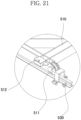
- the transfer frame 510 may include transfer wheels 511 which are respectively located at the corners and roll along the rail portion 530; and seating portions 512 which are respectively located at the corners and on which the lower corner fittings 27 of the foldable container 20 are seated.
- the foldable container 20 is seated on the upper portion of the transfer frame 510 and then the transfer frame 510 may be moved along the rail portion 530, as the transfer chain 520 is moved through the transfer driver 540.
- the introduction unit 100, the operation unit 200, the locking unit 300, and the discharge unit 400 may include a plurality of supports 110 on which the lower corner fittings 27 of the foldable container 20 are respectively seated.
- the plurality of supports 110 may be located such that only an outside portion of the lower corner fittings 27 is mounted, and the rest portion of the lower corner fittings 27 may be located on the seating portion 512 of the transfer frame 510.
- the transfer unit 500 may further include a frame vertical driver (not illustrated) for moving the transfer frame 510 in the vertical direction.
- the transfer unit 500 moves the transfer frame 510 in the upward direction, so that the corner fittings of the foldable container 20 are separated from the support 110, and then the foldable container 20 may be moved in the lateral direction.
- the transfer unit 500 moves the foldable container 20 in the downward direction, so that the lower corner fittings 27 of the foldable container 20 may be seated on the support 110. Accordingly, the transfer unit 500 may improve efficiency by reducing unnecessary space and equipment.
- step S100 the fasteners fastened to the foldable container 20 which is transferred to the introduction unit 100 are disassembled.
- the operator may disassemble the fasteners such as bolts inside and outside the foldable container 20 for keeping the unfolded state of the foldable container 20.
- step S200 the foldable container 20 is transferred to the operation unit 200.
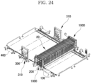
- the transfer frame 510 moves in the upward direction, and the lower corner fittings 27 of the foldable container 20 are separated by a predetermined distance in the upward direction from the support 110 of the introduction unit 100, and then the container 20 is moved to the leftward direction. Therefore, the foldable container 20 obtained by dismantling the fasteners may be located on the operation unit 200 (see FIG. 24 ).
- step S300 the foldable container 20 is folded in the operation unit 200.
- step S300 may include a step of connecting the front and rear panel fastening rods 1310 to the rings 28 on the upper portions of the front and rear panels 24 and 25 of the foldable container 20 (see FIG. 12 ); a step of inserting the upper fixing unit 1200 into the upper corner fitting 26 of the foldable container 20 (see FIG. 13 ); a step of moving the upper panel 22 and the side panel 23 of the foldable container 20 in the upward direction by a predetermined distance; a step of folding the front and rear panels 24 and 25 in the inward direction of the foldable container 20 by using the push portion 1340 (see FIG. 14 ); and a step of lowering the upper panel 22 in the downward direction (refer to FIG. 15 ).
- the upper side panel and the lower side panel of the side panel 23 may be folded inside the foldable container 20.
- the upper reinforcing piece of the upper corner fitting 26 and the lower reinforcing piece of the lower corner fitting 27 are coupled through via fastening member, so that the folded foldable container 20 may not be unfolded.
- step S400 the foldable container 20, which is folded in the operation unit 200, is transferred to the locking unit 300.
- the transfer frame 510 located on the operation unit 200 moves in the upward direction so that the lower corner fittings 27 of the foldable container 20 are spaced a predetermined distance from the support 110 of the operation unit 200, After that, the transfer frame 510 may be moved to the leftward direction so as to move the folded foldable container 20 to the locking unit 300 to be located.
- step S500 the container locking device is inserted into the corner fittings of the foldable container 20 to form the plurality of foldable containers 20 into one bundle unit.
- the step S500 may include a step of inserting the elevation fixing portion 311 into the corner fitting of the folded foldable container 20; a step of transferring the folded foldable container 20 in the upward direction (see FIG. 18 ); a step of transferring another folded foldable container 20 to the lower portion of the folded foldable container 20 (see FIG. 19 ); and a step of coupling the folded foldable containers 20 together by inserting the container locking device into the lower corner fitting 27 of the folded foldable container 20 and the upper corner fitting 26 of the other folded foldable container 20.
- step S500 as illustrated in FIG. 25 , by repeatedly performing such lifting and lowering operations, and coupling operation by of the container locking device, four foldable containers 20 may be stacked, but is not limited thereto, and three or less, or five or more foldable containers 20 may be stacked.
- step S600 referring to FIG. 26 , the plurality of foldable containers 20 in the bundle unit made in the locking unit 300 are transferred to the discharge unit 400.
- the transfer frame 510 located in the locking unit 300 moves in the upward direction so that the lower corner fittings 27 of the foldable container 20 are spaced a predetermined distance from the support 110 of the locking unit 300, and then the transfer frame 510 moves in the leftward direction.
- the plurality of foldable containers 20 in the bundle unit may be moved to the discharge unit 400 to be located.
- the plurality of foldable containers 20 in the bundle unit transferred to the discharge unit 400 may be transferred to the outside by equipment such as the reach stacker.
- a separate fastening device may be fastened.
- the plurality of folded foldable containers 20 may be coupled by coupling a protrusion, which is inserted into a hole of each corner fitting, to a rigid body formed to extend along the corner fittings of the plurality of folded foldable containers 20.
Landscapes
- Engineering & Computer Science (AREA)
- Mechanical Engineering (AREA)
- Rigid Containers With Two Or More Constituent Elements (AREA)
Description
- The present disclosure relates to a foldable container folding device and automatic folding system comprising same.
- In general, a container is installed with beams of four corners as supports, and panels each having a certain area are mutually fastened and assembled on six surfaces between the supports, that is, front, rear, left, right, top, and bottom surfaces with fastening means such as welding or rivets to form a space inside.
- Also, a foldable container is known that transports and unloads cargo therein, and then separates the cargo from a vehicle or a ship to fold an empty container without cargo to be stored or transported.
- A closing and opening operation for folding and unfolding such a foldable container is performed by generally using a reach stacker, a forklift, or the like.
- However, the reach stacker or the forklift is a logistics equipment that handles containers, and it is not possible to perform the opening and closing operation smoothly by stably holding the foldable container in accordance with the order and characteristics of the foldable container opening and closing operation. There is a problem in that foldable container parts are damaged due to the occurrence of misalignment and distortion.
- In addition, there is a problem in that the container is damaged or it takes a long time to open and close the foldable container according to a skill level of a driver of the reach stacker or the forklift.
- In addition, there is a problem in that an enormous cost for opening and closing of the foldable container is required due to the use of the expensive reach stacker or forklift.
- In this regard, in
US 2010-0292063 A1 (title of the invention: device and method for folding and unfolding a foldable transport container), a configuration is disclosed which includes a plurality of actuators; a moving portion driven by an actuator that folds at least one side of a container; an arm driven by the actuator that folds a top and a base of the container; a structure to which the actuator, the moving portion, and the arm are fixed. -
EP 3 296 232 A1 ,KR 2017 0001333 A KR 2015 0078101 A KR 2016 0146027 A - The present application is to solve the problems of the prior art described above, and an object of the present disclosure is to provide a foldable container folding device in which the safety and efficiency of a folding and unfolding operation of the foldable container are improved.
- In addition, another object of the present disclosure is to provide a foldable container automatic folding system in which a foldable container is automatically folded and unfolded by minimizing the use of manpower at each step.
- However, the technical problem to be achieved by the present embodiment is not limited to the technical problems as described above, and other technical problems may exist.
- As technical means for solving the technical problems, a foldable container folding device having the features of claim 1 is proposed.
- On the other hand, a foldable container automatic folding system having the features of claim 11 and a method of folding a foldable container having the features of
claim 26 are proposed. - According to the above-described problem solving means of the present application, the foldable container automatic folding system may automatically fold the foldable container by minimizing the use of manpower at each step, so that safety and efficiency may be significantly improved.
-
-
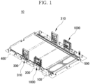
FIG. 1 is a perspective view of a foldable container automatic folding system according to an embodiment of the present disclosure; -
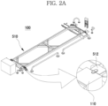
FIGS. 2A and2B are a view for explaining an introduction unit according to an embodiment of the present disclosure; -
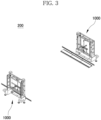
FIG. 3 is a view for explaining an operation unit according to an embodiment of the present disclosure; -
FIG. 4 is a perspective view of a foldable container automatic folding system according to another embodiment of the present disclosure; -
FIG. 5 is a view in which foldable container movable folding and unfolding devices according to an embodiment of the present disclosure are located at front and rear surfaces of the foldable container, respectively; -
FIG. 6 is a perspective view of a foldable container folding device according to an embodiment of the present disclosure; -
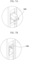
FIGS. 7A and 7B are enlarged views of portion A ofFIG. 6 ; -
FIG. 8 is a view for explaining a front and rear opening/closing unit according to an embodiment of the present disclosure; -
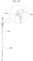
FIGS. 9A and9B are a perspective view and a partially enlarged view of a front and rear panel fastening rod according to an embodiment of the present disclosure; -
FIG. 10 is a perspective view of a push portion and a side wall support according to an embodiment of the present disclosure; -
FIGS. 11A and11B are a view for explaining an elevation opening/closing unit according to an embodiment of the present disclosure; -
FIGS. 12 to 16 are views for explaining a method of folding a foldable container by using the foldable container folding device according to an embodiment of the present disclosure; -
FIG. 17 is a view for explaining a locking unit according to an embodiment of the present disclosure; -
FIGS. 18 and19 are views for explaining a method of locking a plurality of foldable containers by using a locking unit according to an embodiment of the present disclosure; -
FIG. 20 is a view for explaining a transfer unit according to an embodiment of the present disclosure; -
FIG. 21 is an enlarged view of portion B ofFIG. 20 ; -
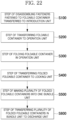
FIG. 22 is a flowchart illustrating a method of folding the foldable container by using the foldable container automatic folding system according to an embodiment of the present disclosure; and -
FIGS. 23 to 26 are views for explaining a method of folding the foldable container by using the foldable container automatic folding system according to an embodiment of the present disclosure. - Hereinafter, embodiments of the present application will be described in detail with reference to the accompanying drawings so that those of ordinary skill in the art may easily implement the present application. However, the present application may be implemented in various different forms and is not limited to the embodiments described herein. In the drawings, parts not related to the description are omitted in order to clearly describe the present application, and similar reference numerals are attached to similar parts throughout the specification.
- Throughout this specification, when a part is said to be "connected" with another part, this includes not only a case that it is "directly connected" but also a case that it is "electrically connected" with another element interposed therebetween.
- In the entire specification of the present application, when a member is located on another member, this includes not only a case in which a certain member is in contact with another member, but also a case in which another member exists between the two members.
- In the entire specification of the present application, when a certain part "includes" a certain component, it means that other components may be further included rather than excluding other components unless specifically stated to the contrary. The terms "about", "substantially", or the like to an extent used throughout this specification are used at or close to the numerical value when manufacturing and material tolerances specific to the stated meaning are presented, and are used to prevent unreasonable use of the stated disclosure, in which accurate or absolute numerical values are used to assist the understanding of the present application, by unscrupulous infringers. As used throughout the specification of the present application, the term "step to" or "step of" does not mean "step for".
- The present application relates to a foldable container folding device and an automatic folding system including the same.
- In addition, a foldable
container folding device 1000 is fixed to the ground and afoldable container 20 is moved to a place where the foldablecontainer folding device 1000 is located, so that thefoldable container 20 may be folded or unfolded, but is not limited thereto. Instead, as illustrated inFIG. 6 , by providingwheels 1500 at a lower portion of amain body 1100, the foldablecontainer folding device 1000 is moved to a place where thefoldable container 20 is located, and thefoldable container 20 may be folded or unfolded. - Prior to describing a foldable container
automatic folding system 10, thefoldable container 20 will be described briefly. - Referring to
FIG. 5 , thefoldable container 20 includes alower panel 21; anupper panel 22 provided parallel to thelower panel 21; aside panel 23 which has upper and lower ends each rotatably connected to theupper panel 22 and thelower panel 21 in a longitudinal direction, and is configured to be folded in an inward direction of thefoldable container 20; and afront panel 24 and arear panel 25 which are rotatably connected in a width direction of thelower panel 21. In addition, anupper corner fitting 26 is located at each corner of theupper panel 22, and alower corner fittings 27 is located at each corner of thelower panel 21. As described above, the longitudinal direction may be the 8 o'clock direction and the 2 o'clock direction ofFIG. 5 , and the width direction may be the 4 o'clock direction and the 10 o'clock direction ofFIG. 5 . - Hereinafter, with reference to
FIG. 1 , the foldable containerautomatic folding system 10 according to an embodiment of the present application will be described briefly. - The foldable container
automatic folding system 10 includes anintroduction unit 100 in which thefoldable container 20 is introduced to be mounted and fasteners fastened to thefoldable container 20 are disassembled for starting the folding operation; anoperation unit 200 which includes foldablecontainer folding device 1000 that are disposed adjacent to theintroduction unit 100 and each located at the front and rear surfaces of thefoldable container 20 to fold and unfold thefoldable container 20; alocking unit 300 which stacks thefoldable containers 20 that are folded after the folding operation is completed to be made into one bundle unit; adischarge unit 400 in which a plurality offoldable containers 20 in the bundle unit made in thelocking unit 300 waits to be transported and stored; and atransfer unit 500 that transfers thefoldable containers 20. - Referring to
FIGS. 1 and2 , theintroduction unit 100 is located at the rightmost side of the foldable containerautomatic folding system 10, and thefoldable container 20 may be moved and located by using a forklift or reach stacker. In addition, in theintroduction unit 100, an operator may disassemble fasteners such as bolts inside and outside thefoldable container 20, which are coupled to maintain an unfolded state of thefoldable container 20. That is, theside panel 23 is divided into an upper side panel and a lower side panel, and the fasteners such as bolts are coupled to maintain the coupled state. Thecontainer 20, in which the fasteners are disassembled, may be transferred from theintroduction unit 100 to theoperation unit 200 by using thetransfer unit 500. In other words, thefoldable container 20 is located such that a part of the outside of the lower corner fitting 27 is mounted on thesupport 110 of theintroduction unit 100, and the rest of the lower corner fitting 27 may be located on aseating portion 512. In addition, referring toFIG. 2B , when transferring thefoldable container 20, as thetransfer frame 510 is moved by a frame lifting/lowering driver by a predetermined distance in the upward direction, theseating unit 512 is located above thesupport 110. Therefore, it is possible to smoothly transfer thefoldable container 20. - Referring to
FIG. 1 , theoperation unit 200 may be located on the left side of theintroduction unit 100, and thefoldable container 20 in which the fasteners are disassembled is moved by thetransfer unit 500 to be located in theoperation unit 200. In addition, with reference toFIG. 3 , in theoperation unit 200, the foldablecontainer folding device 1000 may be located on the front and rear surfaces of thefoldable container 20, respectively. In addition, theoperation unit 200 may perform the folding or unfolding operation of thefoldable container 20. The above-described foldablecontainer folding device 1000 will be described later in detail. - Referring to
FIG. 4 , the foldable containerautomatic folding system 10 may include a plurality ofoperation units - In detail, the
operation units variable operation unit 201 including a moving-type foldablecontainer folding device 1002 that is provided with thewheels 1500 at the lower portion to be movable; and a fixedoperation unit 202 including a fixed-type foldablecontainer folding device 1001. In other words, the foldable containerautomatic folding system 10 is installed in a place where a large number offoldable containers 20 are folded and unfolded, so that the time to make the folded containers in the bundle unit may be reduced. In addition, as illustrated inFIG. 4 , theoperation unit 200 may include twooperation units 200, that is, thevariable operation unit 201 and the fixedoperation unit 202, but is not limited thereto. Thevariable operation unit 201 may be further included to provide three ormore operation units 200. - Hereinafter, the foldable
container folding device 1000 according to an embodiment of the present application will be described with reference toFIGS. 5 to 11 . - As illustrated in
FIG. 5 , the foldablecontainer folding device 1000 are each located on the front and rear surfaces of thefoldable container 20, and may fold or unfold thefoldable container 20. In addition, the foldablecontainer folding device 1000 is located in the foldable containerautomatic folding system 10 to fold or unfold thefoldable container 20, but is not limited thereto, and may be moved to another place, if necessary, to fold or unfold thefoldable container 20. In other words, the foldablecontainer folding device 1000 may be the moving-type foldablecontainer folding device 1002 that is provided with thewheels 1500 under themain body 1100 and is movable. - Referring to
FIG. 6 , the foldablecontainer folding device 1000 includes themain body 1100; anupper fixing unit 1200 provided at the upper portion of themain body 1100 and fixing the upper portion of thefoldable container 20; a front and rear opening/closing unit 1300 provided at the upper portion of themain body 1100, and opening and closing thefront panel 24 or therear panel 25 of thefoldable container 20; and an elevation opening/closing unit 1400 for lifting and lowering theupper panel 22 and theside panel 23 of thefoldable container 20 by lifting and lowering theupper fixing unit 1200. In addition, a plurality ofwheels 1500 are provided under themain body 1100, so that the foldablecontainer folding device 1000 may be easily moved, but is not limited thereto When the foldablecontainer folding device 1000 is used as a fixed type in the foldable containerautomatic folding system 10, thewheels 1500 are unnecessary and thus the foldablecontainer folding device 1000 may be fixed to the ground to be used. - Referring to
FIG. 7A , theupper fixing unit 1200 may be inserted into an insertion groove formed in the upper corner fitting 26 of thefoldable container 20. Illustratively, as illustrated inFIG. 7A , theupper fixing unit 1200 is located on the side portion of thefoldable container 20 to be inserted into the insertion groove formed on the side portion of the upper corner fitting 26, but is not limited thereto, and may be located in a direction of the front surface or the rear surface of thefoldable container 20 to be inserted into an insertion groove formed in the upper corner fitting 26 in the direction of the front surface or the rear surface. - In addition, the
upper fixing unit 1200 may be moved in the longitudinal direction. In other words, as illustrated inFIG. 7B , theupper fixing unit 1200 may be located inside the elevation opening/closing unit 1400, and when in use, as illustrated inFIG. 7A , it may protrude to the outside to be inserted into the insertion groove of the upper corner fitting 26. Furthermore, theupper fixing unit 1200 may be moved in the vertical direction by the elevation opening/closing unit 1400 which is described later. - Referring to
FIGS. 6 and8 , the front and rear opening/closing units 1300 includes a front and rearpanel fastening rod 1310 having one end connected to aring 28 of thefront panel 24 or therear panel 25 and other end rotatably couple; awire 1320 connected to an upper end of the front and rearpanel fastening rod 1310; and awire motor 1330 for winding or unwinding thewire 1320. - In addition, referring to
FIGS. 9A and9B , the front and rearpanel fastening rod 1310 may include anupper fastening rod 1311; alower fastening rod 1312 into which theupper fastening rod 1311 is inserted therein and of which an lower end is rotatably coupled to themain body 1100; awire fixing portion 1314 which is located on an upper portion of theupper fastening rod 1311 and to which thewire 1320 is connected; and aring fixing portion 1313 which is located on the upper portion of theupper fastening rod 1311 and is fixed to thering 28 of thefront panel 24 or therear panel 25. Illustratively, referring toFIG. 9B , the front and rearpanel fastening rod 1310 rotates to be move to thefront panel 24 or therear panel 25, and then moves in the upward direction, thereby being coupled to thering 28 formed in thefront panel 24 or therear panel 25 to be fixed. - In detail, the
ring 28 is formed in each upper portion of thefront panel 24 and therear panel 25, and thering fixing portion 1313 of the front and rearpanel fastening rod 1310 is coupled to thering 28. Thefront panel 24 or therear panel 25 may be folded or unfolded while gradually winding or unwinding thewire 1320 connected to thewire fixing portion 1314 of the front and rearpanel fastening rod 1310 by using thewire motor 1330. At this time, the front and rearpanel fastening rod 1310 includes theupper fastening rod 1311 and thelower fastening rod 1312 to which theupper fastening rod 1311 is coupled, and may extend or contract in the longitudinal direction. In other words, since a rotation axis of the front and rearpanel fastening rod 1310 and a rotation axis of thefront panel 24 or therear panel 25 are different from each other, when thefront panel 24 or therear panel 25 is folded and unfolded, the position of thering 28 of thefront panel 24 or therear panel 25 is different therefrom. Therefore, the front and rearpanel fastening rod 1310 is adjusted in length in the longitudinal direction, so that a fastening state between thering fixing portion 1313 and thering 28 may be maintained during operation. - Referring to
FIGS. 6 and10 , the front and rear opening/closing unit 1300 may further include apush portion 1340 which pushes the central portion of the front andrear panels side support 1350 which is formed to extend in the lateral direction from thepush portion 1340 and is adjusted in length in the lateral direction. - Specifically, the
push portion 1340 may push the central portion of thefront panel 24 or therear panel 25 so that thefront panel 24 or therear panel 25 is rotated to be folded after the front and rearpanel fastening rod 1310 is coupled to thefront panel 24 or therear panel 25. At this time, since thefront panel 24 or therear panel 25 is rotatably coupled in the inward direction of thefoldable container 20, thepush portion 1340 may push thefront panel 24 or therear panel 25 while moving in the inward direction. At this time, theside support 1350 formed to extend from thepush portion 1340 in the lateral direction is elongated in the lateral direction to prevent theside panel 23 from being folded in the inward direction. Thus, front andrear panels container 20 without interference with theside panel 23. - In addition, the
push portion 1340 and theside support 1350 are not coupled to themain body 1100 and may be in a separate configuration formed to be movable from themain body 1100, but are not limited thereto. In addition, as illustrated inFIG. 10 , theside support 1350 may extend or contract in length in the lateral direction. - Referring to
FIGS. 6 and11 , the elevation opening/closing units 1400 are respectively located in the right and left sides of thefront panel 24 or therear panel 25, or opposite positions, so that theupper fixing unit 1200 is inserted into the insertion groove of the upper corner fitting 26. In addition, referring toFIG. 11A , the elevation opening/closing unit 1400 may include apulley 1430 located at the upper portion inside themain body 1100; anelevation wire 1410 of which one end is connected to theupper fixing unit 1200 via thepulley 1430; and anelevation driver 1420 which is located at the lower portion of themain body 1100 and winds or unwinds theelevation wire 1410. In other words, theupper fixing unit 1200 may be connected to theelevation wire 1410 to be moved by theelevation driver 1420 in the vertical direction. In detail, when theupper panel 22 is lowered in the downward direction, theelevation driver 1420 is driven, and theelevation wire 1410 connected to theelevation driver 1420 moves in the upward direction. Theelevation wire 1410 connected to theupper fixing unit 1200 is moved by thepulley 1430 in the downward direction and thereby, theupper panel 22 may be lowered. - In addition, referring to
FIG. 11B , the elevation opening/closing unit 1400 may further include aball screw 1440 which is rotated by theelevation driver 1420, is connected to theelevation wire 1410, and lifts and lowers theupper fixing unit 1200 through theelevation wire 1410 thepulley 1430. Illustratively, theball screw 1440 has a thread formed on an outer circumferential surface, and the other end of thewire 1410 may be connected thereto. As theelevation driver 1420 is driven, theball screw 1440 moves in the vertical direction. Thus, theupper fixing unit 1200 may be moved in the vertical direction. In addition, the elevation opening/closing unit 1400 is located inside a pillar frame of themain body 1100 and may be protected from rain, wind, or the like. - Hereinafter, a method of folding the foldable container by using the foldable container folding device according to an embodiment of the present disclosure will be described in detail.
- First, referring to
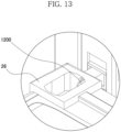
FIGS. 12 and13 , thefoldable container 20 is moved to theoperation unit 200 by using thetransfer unit 500, the foldablecontainer folding device 1000 are respectively located on the front and rear surfaces of thefoldable container 20, and then theupper fixing unit 1200 may be inserted into the insertion groove formed in the upper corner fitting 26 of thefoldable container 20. - Next, referring to
FIGS. 8 and9 , thering fixing portion 1313 of the front and rearpanel fastening rod 1310 is inserted into thering 28 of thefront panel 24 or therear panel 25 to be fixed, and the wire may be connected to thewire fixing portion 1314 of the front and rearpanel fastening rod 1310. - Next, the
upper fixing unit 1200 is moved in the upward direction by a predetermined distance, and thereby theupper panel 22 and theside panel 23 may be moved by a predetermined distance in the upward direction. - Next, referring to
FIGS. 8 and14 , thefront panel 24 or therear panel 25 may be folded by gradually unwinding thewire 1320 by using thewire motor 1330 while pushing thefront panel 24 or therear panel 25 by using thepush portion 1340. At this time, as thepush portion 1340 is moved to the inside of thefoldable container 20, the side support formed to extend in the lateral direction is also moved in the inward direction, and the length thereof is increased in the lateral direction. Therefore, thepush portion 1340 comes into surface contact with theside panel 23 to prevent theside panel 23 from being suddenly folded in the inward direction. When theupper panel 22 and theside panel 23 are moved by a predetermined distance in the upward direction, the upper side panel may be moved upward along a sliding joint which connects the upper side panel and the lower side panel. - Next, referring to
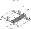
FIG. 15 , theupper fixing unit 1200 is moved in the downward direction to move theupper panel 22 in the downward direction. At this time, the upper side panel and the lower side panel of theside panel 23 are folded in the inward direction of thefoldable container 20. Specifically, the upper side panel is hinged to theupper panel 22, rotates about a portion hinged to theupper panel 22, and thereby the upper side panel may be folded in the inward direction of thefoldable container 20. The lower side panel rotates about a portion hinged to thelower panel 21, and thereby lower side panel may be folded in the inward direction of thefoldable container 20. - In addition, referring to
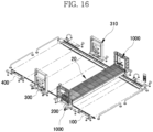
FIG. 16 , after thefoldable container 20 is completely folded, an upper reinforcing piece of the upper corner fitting 26 and a lower reinforcing piece of the lower corner fitting 27 are coupled together through a fastening member, and thereby the foldedfoldable container 20 may be fixed so as not to be unfolded. - Referring to
FIGS. 1 and17 , thelocking unit 300 is located on the left side of theoperation unit 200, stacks thefoldable containers 20 folded in theoperation unit 200, and performs the locking operation to make the foldedfoldable containers 20 in one bundling unit. One bundle unit described above may mean a unit in which four foldedfoldable containers 20 are stacked, but is not limited thereto, and may be 3 or less, or 5 or more. - In detail, in the
locking unit 300, the foldedfoldable containers 20 vertically stacked may be coupled by using thecontainer elevation devices 310 which are respectively located on the front and rear surfaces of the foldedfoldable container 20 to lift and lower the foldedfoldable containers 20 after folding. - To this end, the
container elevation device 310 may include anelevation fixing portion 311 which is inserted into the insertion hole of the upper corner fitting 26 or the lower corner fitting 27 of thefoldable container 20; and anelevation driver 312 which lifts and lowers theelevation fixing portion 311 to lift and lower the foldedfoldable container 20. - In other words, referring to
FIG. 18 , in thelocking unit 300, theelevation fixing portion 311 is inserted into the corner fitting of the foldedfoldable container 20, and then the foldedfoldable container 20 is moved in the upward direction through theelevation driver 312. Therefore, a space, in which another foldedfoldable container 20 may be transferred, may be formed under the foldedfoldable container 20. Thereafter, referring toFIG. 19 , when the other foldedfoldable container 20 is transferred, the container locking device is inserted between the lower corner fitting 27 of the foldedfoldable container 20 located at the upper portion and the upper corner fitting 26 of the foldedfoldable container 20 located at the lower portion to lock the foldedfoldable containers 20 together. In this way, the plurality of foldedfoldable containers 20 may be stacked in one bundle type by the container locking device. - Referring to
FIG. 1 , thedischarge unit 400 is located at the leftmost side of the foldablecontainer folding device 1000, and may be a waiting space for movement by a reach stacker, which is a transport equipment of the plurality offoldable containers 20 in the bundle unit. In other words, when the plurality offoldable containers 20 in the bundle unit are transferred directly from thelocking unit 300 via transfer equipment, thecontainer elevation device 310 is at risk of damage by the transfer equipment. Therefore, theseparate discharge unit 400 for the plurality offoldable containers 20 may be provided to improve the stability. - Referring to
FIG. 20 , thetransfer unit 500 may include arail portion 530 installed along theintroduction unit 100, theoperation unit 200, thelocking unit 300, and thedischarge unit 400; atransfer frame 510 moving thefoldable container 20 along therail portion 530; atransfer chain 520 coupled to thetransfer frame 510; and atransfer driver 540 for moving thetransfer chain 520. - Referring to
FIG. 21 , thetransfer frame 510 may includetransfer wheels 511 which are respectively located at the corners and roll along therail portion 530; andseating portions 512 which are respectively located at the corners and on which thelower corner fittings 27 of thefoldable container 20 are seated. In other words, thefoldable container 20 is seated on the upper portion of thetransfer frame 510 and then thetransfer frame 510 may be moved along therail portion 530, as thetransfer chain 520 is moved through thetransfer driver 540. - In this case, referring again to
FIG. 2 , in order to examine the characteristics of theseating portion 512, theintroduction unit 100, theoperation unit 200, thelocking unit 300, and thedischarge unit 400 may include a plurality ofsupports 110 on which thelower corner fittings 27 of thefoldable container 20 are respectively seated. In addition, the plurality ofsupports 110 may be located such that only an outside portion of thelower corner fittings 27 is mounted, and the rest portion of thelower corner fittings 27 may be located on theseating portion 512 of thetransfer frame 510. In addition, thetransfer unit 500 may further include a frame vertical driver (not illustrated) for moving thetransfer frame 510 in the vertical direction. - In detail, the
transfer unit 500 moves thetransfer frame 510 in the upward direction, so that the corner fittings of thefoldable container 20 are separated from thesupport 110, and then thefoldable container 20 may be moved in the lateral direction. In addition, when thefoldable container 20 arrives at any one selected from theintroduction unit 100, theoperation unit 200, thelocking unit 300, and thedischarge unit 400, thetransfer unit 500 moves thefoldable container 20 in the downward direction, so that thelower corner fittings 27 of thefoldable container 20 may be seated on thesupport 110. Accordingly, thetransfer unit 500 may improve efficiency by reducing unnecessary space and equipment. - Hereinafter, a method of folding the
foldable container 20 by using the foldable containerautomatic folding system 10 according to an embodiment of the present disclosure will be described with reference toFIGS. 22 to 26 . - In step S100, the fasteners fastened to the
foldable container 20 which is transferred to theintroduction unit 100 are disassembled. - In other words, referring to
FIG. 23 , when thefoldable container 20 is located on thesupport 110 of theintroduction unit 100 by using a forklift or a reach stacker, the operator may disassemble the fasteners such as bolts inside and outside thefoldable container 20 for keeping the unfolded state of thefoldable container 20. - In step S200, the
foldable container 20 is transferred to theoperation unit 200. - In other words, the
transfer frame 510 moves in the upward direction, and thelower corner fittings 27 of thefoldable container 20 are separated by a predetermined distance in the upward direction from thesupport 110 of theintroduction unit 100, and then thecontainer 20 is moved to the leftward direction. Therefore, thefoldable container 20 obtained by dismantling the fasteners may be located on the operation unit 200 (seeFIG. 24 ). - In step S300, the
foldable container 20 is folded in theoperation unit 200. - Specifically, step S300 may include a step of connecting the front and rear
panel fastening rods 1310 to therings 28 on the upper portions of the front andrear panels FIG. 12 ); a step of inserting theupper fixing unit 1200 into the upper corner fitting 26 of the foldable container 20 (seeFIG. 13 ); a step of moving theupper panel 22 and theside panel 23 of thefoldable container 20 in the upward direction by a predetermined distance; a step of folding the front andrear panels foldable container 20 by using the push portion 1340 (seeFIG. 14 ); and a step of lowering theupper panel 22 in the downward direction (refer toFIG. 15 ). In addition, in the step of lowering theupper panel 22 in the downward direction, the upper side panel and the lower side panel of theside panel 23 may be folded inside thefoldable container 20. - In addition, after the
foldable container 20 is completely folded, the upper reinforcing piece of the upper corner fitting 26 and the lower reinforcing piece of the lower corner fitting 27 are coupled through via fastening member, so that the foldedfoldable container 20 may not be unfolded. - In step S400, the
foldable container 20, which is folded in theoperation unit 200, is transferred to thelocking unit 300. - In other words, the
transfer frame 510 located on theoperation unit 200 moves in the upward direction so that thelower corner fittings 27 of thefoldable container 20 are spaced a predetermined distance from thesupport 110 of theoperation unit 200, After that, thetransfer frame 510 may be moved to the leftward direction so as to move the foldedfoldable container 20 to thelocking unit 300 to be located. - In step S500, the container locking device is inserted into the corner fittings of the
foldable container 20 to form the plurality offoldable containers 20 into one bundle unit. - Specifically, the step S500 may include a step of inserting the
elevation fixing portion 311 into the corner fitting of the foldedfoldable container 20; a step of transferring the foldedfoldable container 20 in the upward direction (seeFIG. 18 ); a step of transferring another foldedfoldable container 20 to the lower portion of the folded foldable container 20 (seeFIG. 19 ); and a step of coupling the foldedfoldable containers 20 together by inserting the container locking device into the lower corner fitting 27 of the foldedfoldable container 20 and the upper corner fitting 26 of the other foldedfoldable container 20. At this time, in step S500, as illustrated inFIG. 25 , by repeatedly performing such lifting and lowering operations, and coupling operation by of the container locking device, fourfoldable containers 20 may be stacked, but is not limited thereto, and three or less, or five or morefoldable containers 20 may be stacked. - In step S600, referring to
FIG. 26 , the plurality offoldable containers 20 in the bundle unit made in thelocking unit 300 are transferred to thedischarge unit 400. - In other words, the
transfer frame 510 located in thelocking unit 300 moves in the upward direction so that thelower corner fittings 27 of thefoldable container 20 are spaced a predetermined distance from thesupport 110 of thelocking unit 300, and then thetransfer frame 510 moves in the leftward direction. Thus, the plurality offoldable containers 20 in the bundle unit may be moved to thedischarge unit 400 to be located. In addition, the plurality offoldable containers 20 in the bundle unit transferred to thedischarge unit 400 may be transferred to the outside by equipment such as the reach stacker. - In the above, the process of folding and stacking the
foldable containers 20 is described, and the plurality offoldable containers 20 are unfolded in the opposite order when unfolding. - On the other hand, in order to more firmly fasten the plurality of folded
foldable containers 20 in the bundle unit, a separate fastening device may be fastened. For example, the plurality of foldedfoldable containers 20 may be coupled by coupling a protrusion, which is inserted into a hole of each corner fitting, to a rigid body formed to extend along the corner fittings of the plurality of foldedfoldable containers 20. - The foregoing description of the present application is for illustrative purposes only. Therefore, it should be understood that the embodiments described above are illustrative in all respects and not limiting. For example, each component described as a single type may be implemented in a distributed manner, and similarly, components described as being distributed may also be implemented in a combined form.
-
- 10: foldable container automatic folding system
- 100: introduction unit, 110: support
- 200: operation unit
- 300: locking unit, 310: container elevation device
- 311: elevation fixing portion, 312: elevation driver
- 400: discharge unit
- 500: transfer unit
- 510: transfer frame, 511: transfer wheel
- 512: seating portion, 520: transfer chain
- 530: rail portion, 540: transfer driver
- 20: foldable container
- 21: lower panel, 22: upper panel
- 23: side panel, 24: front panel
- 25: rear panel, 26: upper corner fitting
- 27: lower corner fitting
- 1000: foldable container folding device
- 1100: main body
- 1200: upper fixing unit
- 1300: front and rear opening/closing unit
- 1310: front and rear panel fastening rod, 1311: upper fastening rod
- 1312: lower fastening rod, 1313: ring fixing portion
- 1314: wire fixing portion
- 1320: wire, 1330: wire motor
- 1340: push portion, 1350: side support
- 1400: elevation opening/closing unit, 1410: elevation wire
- 1420: elevation driver, 1430: pulley
- 1440: ball screw
- 1500: wheel
Claims (27)
- A foldable container folding device (1000) being adapted for being located at each of a front and a rear of a foldable container and for folding or unfolding the foldable container, comprising:a main body (1100);an upper fixing unit (1200) provided on the upper portion of the main body (1100) for fixing the upper portion of the foldable container;front and rear opening/closing units (1300) provided on the upper portion of the main body (1100) for opening and closing a front panel or a rear panel of the foldable container; andan elevation opening/closing unit (1400) for elevating the upper panel and a side panel of the foldable container configured to elevate the upper fixing unit (1200),characterised in that the front and rear opening/closing unit (1300) includes a front and rear panel fastening rod (1310) having one end connectable to a ring (28) of the front panel or the rear panel and the other end rotatably coupled.
- The foldable container folding device (1000) of claim 1,
wherein the front and rear opening/closing unit (1300) includesa wire (1320) connected to an upper end of the front and rear panel fastening rod (1310); anda wire motor (1330) for winding or unwinding the wire (1320). - The foldable container folding device (1000) of claim 1,
wherein the upper fixing unit (1200) is located to be inserted into an insertion groove located on the side of the upper panel (22) of the foldable container (20). - The foldable container folding device (1000) of claim 1,
wherein the upper fixing unit (1200) is located to be inserted into an insertion groove located at the front or rear of the upper panel (22) of the foldable container (20). - The foldable container folding device (1000) of claim 1,
wherein the upper fixing unit (1200) is movable in a longitudinal direction. - The foldable container folding device (1000) of claim 1,
wherein the front and rear panel fastening rod (1310) includesan upper fastening rod (1311);a lower fastening rod (1312) into which the upper fastening rod (1311) is inserted, and of which a lower end is rotatably coupled to the main body (1100);a wire fixing portion (1314) located on the upper portion of the upper fastening rod (1311) and to which a wire (1320) is connected; anda ring fixing portion (1313) located on the upper portion of the upper fastening rod (1311) and fixable to the ring of the front panel or the rear panel, andwherein the upper fastening rod (1311) is coupled to the lower fastening rod (1312) to be extended or contracted in the longitudinal direction. - The foldable container folding device (1000) of claim 1,
wherein the front and rear opening/closing unit (1300) further includesa push portion (1340) for pushing the front panel (24) or the rear panel (25) toward the inside of the foldable container (20); anda side support (1350) extending in a lateral direction from the push portion (1340) and adjusting a length in the lateral direction. - The foldable container folding device (1000) of claim 1,
wherein the elevation opening/closing unit (1400) includesa pulley (1430) located at an upper portion inside the main body (1100);an elevation wire (1410) having one end connected to the upper fixing unit (1200) via the pulley (1430); andan elevation driver (1420) located at a lower portion of the main body (1100) being adapted for tmd- winding or unwinding the elevation wire (1410). - The foldable container folding device (1000) of claim 8, wherein the elevation opening/closing unit (1400) further includes a ball screw (1440) being rotable by the elevation driver (1420) and connected to the elevation wire (1410) to lift and lower the upper fixing unit (1200) via the elevation wire (1410) and the pulley (1430).
- The foldable container folding device (1000) of claim 1, wherein a plurality of wheels (1500) are provided at the lower portion of the main body (1100).
- A foldable container automatic folding system (10) comprising:an introduction unit (100) in which a foldable container (20) is introducable to be mounted and for disassembling fasteners which are fastened to the foldable container (20) at a position where a folding operation is started;an operation unit (200) which includes foldable container folding devices (1000) that are disposed adjacent to the introduction unit (100) wherein each foldable container folding device is adapted for being located at front and rear surfaces of the foldable container (20) to fold and unfold the foldable container (20);a locking unit (300) which is disposed adjacent to the operation unit (200), for stacking the foldable containers (20) that are folded after the folding operation is completed by the operation unit (200), and for performing a locking operation to make the folded foldable containers (20) into one bundle unit;a discharge unit (400) adapted for a plurality of foldable containers (20) in the bundle unit, made in the locking unit (300), to wait to be transported and stored; anda transfer unit (500) for transfering the foldable containers,wherein the foldable container folding device (1000) includes a main body (1100);an upper fixing unit (1200) which is provided on an upper portion of the main body (1100) and for fixingan upper portion of the foldable container (20);a front and rear opening/closing unit (1300) which is provided on the upper portion of the main body (1100) to open and close a front panel (24) or a rear panel (25) of the foldable container (20); andan elevation opening/closing unit (1400) for lifting and lowering the upper panel (22) and a side panel (23) of the foldable container (20) by lifting and lowering the upper fixing unit (1200),wherein the front and rear opening/closing unit (1300) includes a front and rear panel fastening rod (1310) having one end connected to a ring (28) of the front panel (24) or the rear panel (25) and the other end rotatably coupled.
- The foldable container automatic folding system (10) of claim 11, further comprising:a wire (1320) connected to an upper end of the front and rear panel fastening rod (1310); anda wire motor (1330) for winding or unwinding the wire (1320).
- The foldable container automatic folding system (10) of claim 11, wherein the upper fixing unit (1200) is located to be inserted into an insertion groove located at a side of the upper panel (22) of the foldable container (20).
- The foldable container automatic folding system (10) of claim 11, wherein the upper fixing unit (1200) is located to be inserted into an insertion groove located at the front or rear of the upper panel (22) of the foldable container (20).
- The foldable container automatic folding system (10) of claim 11, wherein the upper fixing unit (1200) is movable in a longitudinal direction.
- The foldable container automatic folding system (10) of claim 11, wherein the front and rear panel fastening rod (1310) includesan upper fastening rod (1311);a lower fastening rod (1312) into which the upper fastening rod (1311) is inserted, and of which a lower end is rotatably coupled to the main body (1100);a wire fixing portion (1314) located on an upper portion of the upper fastening rod (1311) and to which a wire (1320) is connected; anda ring fixing portion (1313) located on the upper portion of the upper fastening rod (1311) and fixed to the ring (28) of the front panel (24) or the rear panel (25), andwherein the upper fastening rod (1311) is coupled to the lower fastening rod (1312) to be extended or contracted in the longitudinal direction.
- The foldable container automatic folding system (10) of claim 11, wherein the front and rear opening/closing unit (1300) further includesa push portion (1340) for pushing the front panel (24) or the rear panel (25) toward the inside of the foldable container (20); anda side support (1350) extending in a lateral direction from the push portion (1340) for adjusting a length in the lateral direction.
- The foldable container automatic folding system (10) of claim 11, wherein the elevation opening/closing unit (1400) includesa pulley (1430) located at an upper portion inside the main body (1100);an elevation wire (1410) having one end connected to the upper fixing unit (1200) via the pulley (1430); andan elevation driver (1420) located at a lower portion of the main body (1100) and winding or unwinding the elevation wire (1410).
- The foldable container automatic folding system (10) of claim 18, wherein the elevation opening/closing unit (1400) further includes a ball screw (1440) being rotable by the elevation driver (1420) and connected to the elevation wire (1410) to lift and lower the upper fixing unit (1200) via the elevation wire (1410) and the pulley (1430).
- The foldable container automatic folding system (10) of claim 11, wherein the operation unit (200) includesa variable operation unit (201) including a moving-type foldable container folding device (1002) that is provided with the wheels (1500) at the lower portion to be movable; anda fixed operation unit (202) including a fixed-type foldable container folding device (1001).
- The foldable container automatic folding system (10) of claim 11, wherein the locking unit (300) includescontainer elevation devices (310) which are each located on the front and rear surfaces to lift and lower the foldable containers (20) after the folding operation is completed, andwherein the container elevation device (310) includesan elevation fixing portion (311) which is inserted into an insertion hole of the upper corner fitting (26) or the lower corner fitting (27) of the foldable container (20); andan elevation driver (312) for lifting and lowering the elevation fixing portion (311) to lift and lower the folded foldable container (20).
- The foldable container automatic folding system (10) of claim 11, wherein the transfer unit (500) includesa rail portion (530) installed along the introduction unit (100), the operation unit (200), the locking unit (300), and the discharge unit (400);a transfer frame (510) for moving the foldable container (20) along the rail portion (530);a transfer chain (520) coupled to the transfer frame (510); anda transfer driver (540) for moving the transfer chain (520).
- The foldable container automatic folding system (10) of claim 22, wherein the transfer frame (510) includestransfer wheels (511) which are respectively located at the corners and roll along the rail portion (530); andseating portions (512) which are respectively located at the corners and on which the lower corner fittings (27) of the foldable container (20) are seated.
- The foldable container automatic folding system (10) of claim 22, wherein the introduction unit (100), the operation unit (200), the locking unit (300), and the discharge unit (400) include a plurality of supports (110) on which the lower corner fittings (27) of the foldable container (20) are respectively seated, and
wherein the plurality of supports (110) are located such that only an outside portion of the lower corner fittings (27) is mounted, and the corners of the transfer frame (510) are located on the rest portion of the lower corner fittings (27). - The foldable container automatic folding system (10) of claim 22, wherein the transfer unit (500) further includes
a frame vertical driver for moving the transfer frame (510) in the vertical direction. - A method of folding a foldable container (20) by using a foldable container automatic folding system (10) according to claim 11, the method comprising:a step of disassembling fasteners fastened to the foldable container (20) which is transferred to an introduction unit (100);a step of transferring the foldable container (20) to an operation unit (200);a step of folding the foldable container (20) in the operation unit (200);a step of transferring the foldable container (20) from the operation unit (200) to a locking unit (300);a step of making a plurality of folded foldable containers (20) into one bundle unit by inserting a container locking device into a corner fitting of the foldable container (20) in the locking unit (300); anda step of transferring the folded foldable containers (20) of the bundle unit made in the locking unit (300) to a discharge unit (400),wherein the step of folding the foldable container (20) in the operation unit (200) includesa step of connecting front and rear panel fastening rods (1310) to rings (28) on upper portions of front and rear panels (24, 25) of the foldable container (20);a step of inserting an upper fixing unit (1200) into an upper corner fitting (26) of the foldable container (20);a step of moving the upper panel (22) and the side panel (23) of the foldable container (20) in an upward direction by a predetermined distance;a step of folding the front and rear panels (24, 25) in an inward direction of the foldable container (20) by using a push portion (1340); anda step of lowering the upper panel (22) in a downward direction.
- The method of folding a foldable container (20) of claim 26, wherein the step of making the plurality of folded foldable containers (20) into one bundle unit includesa step of inserting an elevation fixing portion (311) into a corner fitting of the folded foldable container (20);a step of transferring the folded foldable container (20) in the upward direction;a step of transferring another folded foldable container (20) to a lower portion of the folded foldable container (20); anda step of coupling the foldable containers (20) together by inserting a container locking device into a lower corner (27) fitting of the folded foldable container (20) and an upper corner fitting (26) of the other folded foldable container (20).
Applications Claiming Priority (2)
| Application Number | Priority Date | Filing Date | Title |
|---|---|---|---|
| KR1020180109232A KR102108108B1 (en) | 2018-09-12 | 2018-09-12 | Apparatus for folding and unfolding foldable container and automatic folding system having the same |
| PCT/KR2019/009377 WO2020054969A1 (en) | 2018-09-12 | 2019-07-29 | Foldable container folding device and automatic folding system comprising same |
Publications (3)
| Publication Number | Publication Date |
|---|---|
| EP3838799A1 EP3838799A1 (en) | 2021-06-23 |
| EP3838799A4 EP3838799A4 (en) | 2022-05-11 |
| EP3838799B1 true EP3838799B1 (en) | 2023-09-06 |
Family
ID=69777940
Family Applications (1)
| Application Number | Title | Priority Date | Filing Date |
|---|---|---|---|
| EP19860733.5A Active EP3838799B1 (en) | 2018-09-12 | 2019-07-29 | Foldable container folding device, automatic folding system comprising same, method of folding a foldable container |
Country Status (4)
| Country | Link |
|---|---|
| US (1) | US12319492B2 (en) |
| EP (1) | EP3838799B1 (en) |
| KR (1) | KR102108108B1 (en) |
| WO (1) | WO2020054969A1 (en) |
Families Citing this family (2)
| Publication number | Priority date | Publication date | Assignee | Title |
|---|---|---|---|---|
| KR102367367B1 (en) * | 2020-03-25 | 2022-02-24 | 씨스존 주식회사 | Folding Equipment For Logistics Container |
| CN119212935A (en) * | 2022-05-19 | 2024-12-27 | 思派克泰纳私人有限公司 | Intermodal container handling systems |
Family Cites Families (26)
| Publication number | Priority date | Publication date | Assignee | Title |
|---|---|---|---|---|
| US4553954A (en) * | 1981-04-17 | 1985-11-19 | Western Packaging Systems, Ltd. | Automatic case erector and sealer |
| JP3003652U (en) * | 1994-04-28 | 1994-10-25 | ナショナル金属工業株式会社 | Automatic container folding device |
| JP3030297U (en) * | 1996-04-17 | 1996-10-22 | 矢崎化工株式会社 | Automatic folding device for foldable containers |
| JP3003652B2 (en) | 1997-11-17 | 2000-01-31 | 日本電気株式会社 | Method for manufacturing semiconductor device |
| US6105126A (en) | 1998-04-30 | 2000-08-15 | International Business Machines Corporation | Address bit decoding for same adder circuitry for RXE instruction format with same XBD location as RX format and dis-jointed extended operation code |
| ITBO20020521A1 (en) * | 2002-08-05 | 2004-02-06 | Gd Spa | METHOD AND MACHINE FOR PACKAGING A PRODUCT |
| US7287360B2 (en) * | 2004-11-05 | 2007-10-30 | Wexxar Packaging, Inc. | Bottom taping system using a pusher feed |
| US7192393B2 (en) * | 2004-11-05 | 2007-03-20 | Wexxar Packaging Inc. | Carton flap gripping system |
| US7585265B2 (en) * | 2006-05-15 | 2009-09-08 | Frito-Lay North America, Inc. | Fan-folding mechanism for a case erector |
| WO2008122984A2 (en) | 2007-04-09 | 2008-10-16 | Indian Institute Of Technology, Delhi | An apparatus and a method for folding and unfolding a foldable transport container |
| US8128547B2 (en) * | 2007-10-10 | 2012-03-06 | Smurfit-Stone Container Enterprises, Inc. | Methods and machines for forming a polygonal container |
| DE102008000493B4 (en) * | 2008-03-03 | 2009-11-19 | Hoffmann, Konrad | folding container |
| CL2011003232A1 (en) * | 2011-12-21 | 2012-07-13 | Claudio De Los Sagrados Corazones Arteaga Reyes | Collapsible container comprising a floor, a front panel with access doors, a rear panel, a roof, right and left side walls, hinged joints or joints, lateral anchoring means, means for blocking the folding down of the panels and means for blocking or unlock the fold; method; use; system. |
| US20190160774A1 (en) * | 2012-04-24 | 2019-05-30 | H. J. Paul Langen | Method and apparatus for forming containers |
| JP5545357B2 (en) * | 2012-12-25 | 2014-07-09 | 株式会社安川電機 | Robot system and robot |
| ITBO20130388A1 (en) * | 2013-07-23 | 2015-01-24 | Gd Spa | UNIT AND METHOD OF WRAPPING FOR THE BENDING OF A BLOCKED IN A PACKING MACHINE. |
| KR101534619B1 (en) | 2013-12-30 | 2015-07-09 | 한국철도기술연구원 | Folding device for Foldable Container |
| EP3064343B1 (en) * | 2015-03-02 | 2019-01-30 | Tetra Laval Holdings & Finance S.A. | A folding apparatus for folding sheet packaging elements |
| KR101754199B1 (en) | 2015-06-26 | 2017-07-06 | 한국철도기술연구원 | Folding device for foldable container |
| KR101754192B1 (en) | 2015-06-11 | 2017-07-06 | 한국철도기술연구원 | Foldable container |
| JP6567093B2 (en) * | 2015-06-11 | 2019-08-28 | コリア レイルロード リサーチ インスティテュート | Foldable container |
| KR101770607B1 (en) | 2015-12-03 | 2017-08-24 | 한국철도기술연구원 | A locking device for containers |
| US11780197B2 (en) * | 2016-09-25 | 2023-10-10 | Pearson Packaging Systems | Tool for use in robotic case erecting |
| US11173686B2 (en) * | 2017-08-25 | 2021-11-16 | Wexxar Packaging, Inc. | Apparatus and method for accurate carton formation |
| JP7180857B2 (en) * | 2018-02-27 | 2022-11-30 | 株式会社イシダ | Carton-making, boxing, and sealing equipment |
| JP7384373B2 (en) * | 2019-02-13 | 2023-11-21 | 株式会社イシダ | Cardboard box assembly equipment |
-
2018
- 2018-09-12 KR KR1020180109232A patent/KR102108108B1/en active Active
-
2019
- 2019-07-29 WO PCT/KR2019/009377 patent/WO2020054969A1/en not_active Ceased
- 2019-07-29 EP EP19860733.5A patent/EP3838799B1/en active Active
- 2019-07-29 US US17/275,501 patent/US12319492B2/en active Active
Also Published As
| Publication number | Publication date |
|---|---|
| KR20200030402A (en) | 2020-03-20 |
| EP3838799A1 (en) | 2021-06-23 |
| US12319492B2 (en) | 2025-06-03 |
| EP3838799A4 (en) | 2022-05-11 |
| WO2020054969A1 (en) | 2020-03-19 |
| KR102108108B1 (en) | 2020-05-11 |
| US20220033176A1 (en) | 2022-02-03 |
Similar Documents
| Publication | Publication Date | Title |
|---|---|---|
| US11618488B2 (en) | Foldable container and apparatus for folding and unfolding the same | |
| NL2009992C2 (en) | Collapsible transport container. | |
| US20110072596A1 (en) | Extendable ramp for storage in a tailgate or flat bed | |
| US20060226143A1 (en) | Collapsible container system | |
| US7722101B2 (en) | Cargo shipping container spreader and method | |
| US20080188364A1 (en) | Method and machine for constructing a collapsible bulk bin | |
| US8240496B2 (en) | Collapsible container and hinge used for collapsible container | |
| US20190053618A1 (en) | Folding storage unit | |
| US20100204030A1 (en) | Collapsed Tubular Carton Erecting Apparatus & Methods | |
| US12319492B2 (en) | Foldable container folding device and automatic folding system comprising same | |
| AU739733B2 (en) | Multi-deck container | |
| US20110073595A1 (en) | Collapsible freight container | |
| EP3205604A1 (en) | System and method for locking walls of a storage container | |
| US20220089359A1 (en) | Foldable container having corner locking structure | |
| KR101754199B1 (en) | Folding device for foldable container | |
| WO2002057113A1 (en) | A collapsible framework | |
| EP3901061B1 (en) | Foldable container | |
| CN223467637U (en) | Double-layer integrated folding box type structure | |
| KR101605855B1 (en) | Container of side open and shut type | |
| US11225374B2 (en) | Collapsible shipping container actuator | |
| WO2004052754A1 (en) | Container having device for opening and shutting the top cover of it | |
| WO2008010999A2 (en) | Cargo shipping container spreader and method | |
| AU2018253481B2 (en) | Storage container | |
| EP3901064A1 (en) | Foldable container including torsion bar module for collapsing side panel | |
| JP2002138580A (en) | Stretchable, movable accommodation in the workplace |
Legal Events
| Date | Code | Title | Description |
|---|---|---|---|
| STAA | Information on the status of an ep patent application or granted ep patent |
Free format text: STATUS: THE INTERNATIONAL PUBLICATION HAS BEEN MADE |
|
| PUAI | Public reference made under article 153(3) epc to a published international application that has entered the european phase |
Free format text: ORIGINAL CODE: 0009012 |
|
| STAA | Information on the status of an ep patent application or granted ep patent |
Free format text: STATUS: REQUEST FOR EXAMINATION WAS MADE |
|
| 17P | Request for examination filed |
Effective date: 20210311 |
|
| AK | Designated contracting states |
Kind code of ref document: A1 Designated state(s): AL AT BE BG CH CY CZ DE DK EE ES FI FR GB GR HR HU IE IS IT LI LT LU LV MC MK MT NL NO PL PT RO RS SE SI SK SM TR |
|
| DAV | Request for validation of the european patent (deleted) | ||
| DAX | Request for extension of the european patent (deleted) | ||
| A4 | Supplementary search report drawn up and despatched |
Effective date: 20220412 |
|
| RIC1 | Information provided on ipc code assigned before grant |
Ipc: B65D 90/00 20060101ALI20220406BHEP Ipc: B65D 88/52 20060101AFI20220406BHEP |
|
| GRAP | Despatch of communication of intention to grant a patent |
Free format text: ORIGINAL CODE: EPIDOSNIGR1 |
|
| STAA | Information on the status of an ep patent application or granted ep patent |
Free format text: STATUS: GRANT OF PATENT IS INTENDED |
|
| INTG | Intention to grant announced |
Effective date: 20230405 |
|
| GRAS | Grant fee paid |
Free format text: ORIGINAL CODE: EPIDOSNIGR3 |
|
| GRAA | (expected) grant |
Free format text: ORIGINAL CODE: 0009210 |
|
| STAA | Information on the status of an ep patent application or granted ep patent |
Free format text: STATUS: THE PATENT HAS BEEN GRANTED |
|
| AK | Designated contracting states |
Kind code of ref document: B1 Designated state(s): AL AT BE BG CH CY CZ DE DK EE ES FI FR GB GR HR HU IE IS IT LI LT LU LV MC MK MT NL NO PL PT RO RS SE SI SK SM TR |
|
| REG | Reference to a national code |
Ref country code: GB Ref legal event code: FG4D |
|
| REG | Reference to a national code |
Ref country code: CH Ref legal event code: EP |
|
| REG | Reference to a national code |
Ref country code: IE Ref legal event code: FG4D |
|
| REG | Reference to a national code |
Ref country code: DE Ref legal event code: R096 Ref document number: 602019037082 Country of ref document: DE |
|
| REG | Reference to a national code |
Ref country code: NL Ref legal event code: FP |
|
| REG | Reference to a national code |
Ref country code: LT Ref legal event code: MG9D |
|
| PG25 | Lapsed in a contracting state [announced via postgrant information from national office to epo] |
Ref country code: GR Free format text: LAPSE BECAUSE OF FAILURE TO SUBMIT A TRANSLATION OF THE DESCRIPTION OR TO PAY THE FEE WITHIN THE PRESCRIBED TIME-LIMIT Effective date: 20231207 |
|
| PG25 | Lapsed in a contracting state [announced via postgrant information from national office to epo] |
Ref country code: SE Free format text: LAPSE BECAUSE OF FAILURE TO SUBMIT A TRANSLATION OF THE DESCRIPTION OR TO PAY THE FEE WITHIN THE PRESCRIBED TIME-LIMIT Effective date: 20230906 Ref country code: RS Free format text: LAPSE BECAUSE OF FAILURE TO SUBMIT A TRANSLATION OF THE DESCRIPTION OR TO PAY THE FEE WITHIN THE PRESCRIBED TIME-LIMIT Effective date: 20230906 Ref country code: NO Free format text: LAPSE BECAUSE OF FAILURE TO SUBMIT A TRANSLATION OF THE DESCRIPTION OR TO PAY THE FEE WITHIN THE PRESCRIBED TIME-LIMIT Effective date: 20231206 Ref country code: LV Free format text: LAPSE BECAUSE OF FAILURE TO SUBMIT A TRANSLATION OF THE DESCRIPTION OR TO PAY THE FEE WITHIN THE PRESCRIBED TIME-LIMIT Effective date: 20230906 Ref country code: LT Free format text: LAPSE BECAUSE OF FAILURE TO SUBMIT A TRANSLATION OF THE DESCRIPTION OR TO PAY THE FEE WITHIN THE PRESCRIBED TIME-LIMIT Effective date: 20230906 Ref country code: HR Free format text: LAPSE BECAUSE OF FAILURE TO SUBMIT A TRANSLATION OF THE DESCRIPTION OR TO PAY THE FEE WITHIN THE PRESCRIBED TIME-LIMIT Effective date: 20230906 Ref country code: GR Free format text: LAPSE BECAUSE OF FAILURE TO SUBMIT A TRANSLATION OF THE DESCRIPTION OR TO PAY THE FEE WITHIN THE PRESCRIBED TIME-LIMIT Effective date: 20231207 Ref country code: FI Free format text: LAPSE BECAUSE OF FAILURE TO SUBMIT A TRANSLATION OF THE DESCRIPTION OR TO PAY THE FEE WITHIN THE PRESCRIBED TIME-LIMIT Effective date: 20230906 |
|
| REG | Reference to a national code |
Ref country code: AT Ref legal event code: MK05 Ref document number: 1608294 Country of ref document: AT Kind code of ref document: T Effective date: 20230906 |
|
| PG25 | Lapsed in a contracting state [announced via postgrant information from national office to epo] |
Ref country code: IS Free format text: LAPSE BECAUSE OF FAILURE TO SUBMIT A TRANSLATION OF THE DESCRIPTION OR TO PAY THE FEE WITHIN THE PRESCRIBED TIME-LIMIT Effective date: 20240106 |
|
| PG25 | Lapsed in a contracting state [announced via postgrant information from national office to epo] |
Ref country code: AT Free format text: LAPSE BECAUSE OF FAILURE TO SUBMIT A TRANSLATION OF THE DESCRIPTION OR TO PAY THE FEE WITHIN THE PRESCRIBED TIME-LIMIT Effective date: 20230906 |
|
| PG25 | Lapsed in a contracting state [announced via postgrant information from national office to epo] |
Ref country code: ES Free format text: LAPSE BECAUSE OF FAILURE TO SUBMIT A TRANSLATION OF THE DESCRIPTION OR TO PAY THE FEE WITHIN THE PRESCRIBED TIME-LIMIT Effective date: 20230906 |
|
| PG25 | Lapsed in a contracting state [announced via postgrant information from national office to epo] |
Ref country code: SM Free format text: LAPSE BECAUSE OF FAILURE TO SUBMIT A TRANSLATION OF THE DESCRIPTION OR TO PAY THE FEE WITHIN THE PRESCRIBED TIME-LIMIT Effective date: 20230906 Ref country code: RO Free format text: LAPSE BECAUSE OF FAILURE TO SUBMIT A TRANSLATION OF THE DESCRIPTION OR TO PAY THE FEE WITHIN THE PRESCRIBED TIME-LIMIT Effective date: 20230906 Ref country code: IS Free format text: LAPSE BECAUSE OF FAILURE TO SUBMIT A TRANSLATION OF THE DESCRIPTION OR TO PAY THE FEE WITHIN THE PRESCRIBED TIME-LIMIT Effective date: 20240106 Ref country code: ES Free format text: LAPSE BECAUSE OF FAILURE TO SUBMIT A TRANSLATION OF THE DESCRIPTION OR TO PAY THE FEE WITHIN THE PRESCRIBED TIME-LIMIT Effective date: 20230906 Ref country code: EE Free format text: LAPSE BECAUSE OF FAILURE TO SUBMIT A TRANSLATION OF THE DESCRIPTION OR TO PAY THE FEE WITHIN THE PRESCRIBED TIME-LIMIT Effective date: 20230906 Ref country code: CZ Free format text: LAPSE BECAUSE OF FAILURE TO SUBMIT A TRANSLATION OF THE DESCRIPTION OR TO PAY THE FEE WITHIN THE PRESCRIBED TIME-LIMIT Effective date: 20230906 Ref country code: AT Free format text: LAPSE BECAUSE OF FAILURE TO SUBMIT A TRANSLATION OF THE DESCRIPTION OR TO PAY THE FEE WITHIN THE PRESCRIBED TIME-LIMIT Effective date: 20230906 Ref country code: PT Free format text: LAPSE BECAUSE OF FAILURE TO SUBMIT A TRANSLATION OF THE DESCRIPTION OR TO PAY THE FEE WITHIN THE PRESCRIBED TIME-LIMIT Effective date: 20240108 Ref country code: SK Free format text: LAPSE BECAUSE OF FAILURE TO SUBMIT A TRANSLATION OF THE DESCRIPTION OR TO PAY THE FEE WITHIN THE PRESCRIBED TIME-LIMIT Effective date: 20230906 |
|
| PG25 | Lapsed in a contracting state [announced via postgrant information from national office to epo] |
Ref country code: PL Free format text: LAPSE BECAUSE OF FAILURE TO SUBMIT A TRANSLATION OF THE DESCRIPTION OR TO PAY THE FEE WITHIN THE PRESCRIBED TIME-LIMIT Effective date: 20230906 Ref country code: IT Free format text: LAPSE BECAUSE OF FAILURE TO SUBMIT A TRANSLATION OF THE DESCRIPTION OR TO PAY THE FEE WITHIN THE PRESCRIBED TIME-LIMIT Effective date: 20230906 |
|
| REG | Reference to a national code |
Ref country code: DE Ref legal event code: R097 Ref document number: 602019037082 Country of ref document: DE |
|
| PG25 | Lapsed in a contracting state [announced via postgrant information from national office to epo] |
Ref country code: DK Free format text: LAPSE BECAUSE OF FAILURE TO SUBMIT A TRANSLATION OF THE DESCRIPTION OR TO PAY THE FEE WITHIN THE PRESCRIBED TIME-LIMIT Effective date: 20230906 |
|
| PLBE | No opposition filed within time limit |
Free format text: ORIGINAL CODE: 0009261 |
|
| STAA | Information on the status of an ep patent application or granted ep patent |
Free format text: STATUS: NO OPPOSITION FILED WITHIN TIME LIMIT |
|
| PG25 | Lapsed in a contracting state [announced via postgrant information from national office to epo] |
Ref country code: DK Free format text: LAPSE BECAUSE OF FAILURE TO SUBMIT A TRANSLATION OF THE DESCRIPTION OR TO PAY THE FEE WITHIN THE PRESCRIBED TIME-LIMIT Effective date: 20230906 Ref country code: SI Free format text: LAPSE BECAUSE OF FAILURE TO SUBMIT A TRANSLATION OF THE DESCRIPTION OR TO PAY THE FEE WITHIN THE PRESCRIBED TIME-LIMIT Effective date: 20230906 |
|
| 26N | No opposition filed |
Effective date: 20240607 |
|
| PG25 | Lapsed in a contracting state [announced via postgrant information from national office to epo] |
Ref country code: BG Free format text: LAPSE BECAUSE OF FAILURE TO SUBMIT A TRANSLATION OF THE DESCRIPTION OR TO PAY THE FEE WITHIN THE PRESCRIBED TIME-LIMIT Effective date: 20230906 |
|
| PG25 | Lapsed in a contracting state [announced via postgrant information from national office to epo] |
Ref country code: BG Free format text: LAPSE BECAUSE OF FAILURE TO SUBMIT A TRANSLATION OF THE DESCRIPTION OR TO PAY THE FEE WITHIN THE PRESCRIBED TIME-LIMIT Effective date: 20230906 |
|
| PG25 | Lapsed in a contracting state [announced via postgrant information from national office to epo] |
Ref country code: MC Free format text: LAPSE BECAUSE OF FAILURE TO SUBMIT A TRANSLATION OF THE DESCRIPTION OR TO PAY THE FEE WITHIN THE PRESCRIBED TIME-LIMIT Effective date: 20230906 |
|
| REG | Reference to a national code |
Ref country code: CH Ref legal event code: PL |
|
| PG25 | Lapsed in a contracting state [announced via postgrant information from national office to epo] |
Ref country code: LU Free format text: LAPSE BECAUSE OF NON-PAYMENT OF DUE FEES Effective date: 20240729 |
|
| PG25 | Lapsed in a contracting state [announced via postgrant information from national office to epo] |
Ref country code: LU Free format text: LAPSE BECAUSE OF NON-PAYMENT OF DUE FEES Effective date: 20240729 |
|
| PG25 | Lapsed in a contracting state [announced via postgrant information from national office to epo] |
Ref country code: CH Free format text: LAPSE BECAUSE OF NON-PAYMENT OF DUE FEES Effective date: 20240731 Ref country code: BE Free format text: LAPSE BECAUSE OF NON-PAYMENT OF DUE FEES Effective date: 20240731 |
|
| REG | Reference to a national code |
Ref country code: BE Ref legal event code: MM Effective date: 20240731 |
|
| PGFP | Annual fee paid to national office [announced via postgrant information from national office to epo] |
Ref country code: GB Payment date: 20250605 Year of fee payment: 7 |
|
| PGFP | Annual fee paid to national office [announced via postgrant information from national office to epo] |
Ref country code: NL Payment date: 20250613 Year of fee payment: 7 |
|
| PGFP | Annual fee paid to national office [announced via postgrant information from national office to epo] |
Ref country code: FR Payment date: 20250610 Year of fee payment: 7 |
|
| PG25 | Lapsed in a contracting state [announced via postgrant information from national office to epo] |
Ref country code: IE Free format text: LAPSE BECAUSE OF NON-PAYMENT OF DUE FEES Effective date: 20240729 |
|
| PGFP | Annual fee paid to national office [announced via postgrant information from national office to epo] |
Ref country code: DE Payment date: 20250604 Year of fee payment: 7 |
|
| PG25 | Lapsed in a contracting state [announced via postgrant information from national office to epo] |
Ref country code: CY Free format text: LAPSE BECAUSE OF FAILURE TO SUBMIT A TRANSLATION OF THE DESCRIPTION OR TO PAY THE FEE WITHIN THE PRESCRIBED TIME-LIMIT; INVALID AB INITIO Effective date: 20190729 |
|
| PG25 | Lapsed in a contracting state [announced via postgrant information from national office to epo] |
Ref country code: HU Free format text: LAPSE BECAUSE OF FAILURE TO SUBMIT A TRANSLATION OF THE DESCRIPTION OR TO PAY THE FEE WITHIN THE PRESCRIBED TIME-LIMIT; INVALID AB INITIO Effective date: 20190729 |
|
| PG25 | Lapsed in a contracting state [announced via postgrant information from national office to epo] |
Ref country code: TR Free format text: LAPSE BECAUSE OF FAILURE TO SUBMIT A TRANSLATION OF THE DESCRIPTION OR TO PAY THE FEE WITHIN THE PRESCRIBED TIME-LIMIT Effective date: 20230906 |