EP3838742A1 - Joint joining an aircraft wing to an aircraft body - Google Patents
Joint joining an aircraft wing to an aircraft body Download PDFInfo
- Publication number
- EP3838742A1 EP3838742A1 EP20215650.1A EP20215650A EP3838742A1 EP 3838742 A1 EP3838742 A1 EP 3838742A1 EP 20215650 A EP20215650 A EP 20215650A EP 3838742 A1 EP3838742 A1 EP 3838742A1
- Authority
- EP
- European Patent Office
- Prior art keywords
- panel
- splice
- leg
- skin
- fasteners
- Prior art date
- Legal status (The legal status is an assumption and is not a legal conclusion. Google has not performed a legal analysis and makes no representation as to the accuracy of the status listed.)
- Granted
Links
Images



Classifications
-
- B—PERFORMING OPERATIONS; TRANSPORTING
- B64—AIRCRAFT; AVIATION; COSMONAUTICS
- B64C—AEROPLANES; HELICOPTERS
- B64C1/00—Fuselages; Constructional features common to fuselages, wings, stabilising surfaces or the like
- B64C1/06—Frames; Stringers; Longerons ; Fuselage sections
- B64C1/068—Fuselage sections
- B64C1/069—Joining arrangements therefor
-
- B—PERFORMING OPERATIONS; TRANSPORTING
- B64—AIRCRAFT; AVIATION; COSMONAUTICS
- B64C—AEROPLANES; HELICOPTERS
- B64C1/00—Fuselages; Constructional features common to fuselages, wings, stabilising surfaces or the like
- B64C1/06—Frames; Stringers; Longerons ; Fuselage sections
- B64C1/12—Construction or attachment of skin panels
-
- B—PERFORMING OPERATIONS; TRANSPORTING
- B64—AIRCRAFT; AVIATION; COSMONAUTICS
- B64C—AEROPLANES; HELICOPTERS
- B64C1/00—Fuselages; Constructional features common to fuselages, wings, stabilising surfaces or the like
- B64C1/26—Attaching the wing or tail units or stabilising surfaces
-
- B—PERFORMING OPERATIONS; TRANSPORTING
- B64—AIRCRAFT; AVIATION; COSMONAUTICS
- B64F—GROUND OR AIRCRAFT-CARRIER-DECK INSTALLATIONS SPECIALLY ADAPTED FOR USE IN CONNECTION WITH AIRCRAFT; DESIGNING, MANUFACTURING, ASSEMBLING, CLEANING, MAINTAINING OR REPAIRING AIRCRAFT, NOT OTHERWISE PROVIDED FOR; HANDLING, TRANSPORTING, TESTING OR INSPECTING AIRCRAFT COMPONENTS, NOT OTHERWISE PROVIDED FOR
- B64F5/00—Designing, manufacturing, assembling, cleaning, maintaining or repairing aircraft, not otherwise provided for; Handling, transporting, testing or inspecting aircraft components, not otherwise provided for
- B64F5/10—Manufacturing or assembling aircraft, e.g. jigs therefor
-
- B—PERFORMING OPERATIONS; TRANSPORTING
- B64—AIRCRAFT; AVIATION; COSMONAUTICS
- B64C—AEROPLANES; HELICOPTERS
- B64C1/00—Fuselages; Constructional features common to fuselages, wings, stabilising surfaces or the like
- B64C2001/0054—Fuselage structures substantially made from particular materials
- B64C2001/0072—Fuselage structures substantially made from particular materials from composite materials
-
- B—PERFORMING OPERATIONS; TRANSPORTING
- B64—AIRCRAFT; AVIATION; COSMONAUTICS
- B64C—AEROPLANES; HELICOPTERS
- B64C1/00—Fuselages; Constructional features common to fuselages, wings, stabilising surfaces or the like
- B64C2001/0054—Fuselage structures substantially made from particular materials
- B64C2001/0081—Fuselage structures substantially made from particular materials from metallic materials
Definitions
- This disclosure pertains to the construction of a joint joining portions of an aircraft. More specifically, this disclosure pertains to the construction of a joint that is one of the main connections between an aircraft wing and a fuselage of an aircraft body.
- one or more lap splices may be used as part of the construction attaching the aircraft wing to the aircraft body.
- an upstanding leg panel or a leg panel extending upwardly from the aircraft wing is overlapped with a skin panel on a side of the aircraft body.
- the overlapped leg panel and skin panel are then drilled through, preparing holes for fasteners to be inserted through the holes to secure the leg panel to the skin panel.
- an upstanding leg panel of an overwing T chord which is typically constructed of a metallic material, is overlapped with a skin panel of the fuselage of the aircraft body, which is typically constructed of a composite or aluminum material.
- the holes for the fasteners used in attaching the leg panel to the skin panel are drilled through the leg panel overlapping the skin panel.
- Drilling the fastener holes through the metallic material of the leg panel often results in burrs being formed at the edge of the entry of the fastener hole drilled through the leg panel and at the edge of the exit of the fastener hole drilled through the leg panel.
- a burr or burrs are more often created at the exit edge of the fastener hole drilled through the metallic material of the leg panel.
- a burr is a small, raised or projecting edge or point of the metallic material at the exit edge of the drilled hole.
- the burrs created at the exit edge of the fastener hole function as a notch formed at the exit edge.
- the notch formed by the burr at the exit edge of the fastener hole can be a starting point of a crack formed in the metallic material of the leg panel.
- the notch formed by a burr at an exit edge of a fastener hole creates a fatigue critical region in a joint and the notch must be removed.
- the edge of the fastener hole In order to remove the burrs from the exit edge of the fastener hole drilled through the leg panel, and possibly also from the entry edge of the fastener hole, the edge of the fastener hole must be accessed by a deburring tool.
- the deburring tool machines around the edge of the fastener hole and basically forms the edge of the fastener hole as a chamfered surface or a beveled edge surface around the opening of the fastener hole. This eliminates any potential crack forming in the metallic material of the leg panel at the edge of the fastener hole. However, it is often difficult to access the exit edge of the fastener hole with the deburring tool.
- the joint joining an aircraft wing to an aircraft body of this disclosure avoids the increase in production time and increase in production cost associated with removing burrs from an exit edge of a fastener hole drilled through a metallic panel. This is accomplished by simplifying the access to the exit edge of the fastener hole. This reduces the time required to access the exit edge of the fastener hole to remove burrs from the exit edge of the fastener hole, and thereby reduces production time and production cost.
- the construction of the joint of this disclosure joins a skin panel on a side of the aircraft body to a leg panel extending upwardly from the aircraft wing.
- the skin panel is an external, fuselage skin panel on a side of the aircraft body.
- the skin panel is constructed of a composite or a metallic material.
- the skin panel has an exterior surface that is directed toward an exterior of the aircraft body and an opposite interior surface that is directed toward an interior of the aircraft body.
- the skin panel has a bottom edge surface that extends between the exterior surface of the skin panel and the interior surface of the skin panel.
- the aircraft wing has a top surface and an opposite bottom surface.
- the aircraft wing is constructed with an over wing T chord located at the Side-of-Body Rib on the top surface of the aircraft wing.
- An upstanding leg panel of the T chord extends upwardly from the T chord.
- the leg panel extends upwardly from the top surface of the aircraft wing.
- the leg panel is constructed of a metallic material, such as titanium, aluminum or other equivalent material.
- the leg panel has an exterior surface directed toward the exterior of the aircraft body and an opposite interior surface directed toward the interior of the aircraft body.
- the leg panel has a top edge surface that extends between the exterior surface of the leg panel and the interior surface of the leg panel.
- a splice panel is used in joining the aircraft wing to the aircraft body.
- the splice panel is constructed of a composite material or metallic material such as aluminum or titanium.
- the splice panel has an exterior surface and an opposite interior surface. The interior surface of the splice panel engages in surface engagement with the exterior surface of the leg panel and engages in surface engagement with the exterior surface of the skin panel.
- the skin panel and the leg panel are positioned in a single vertically oriented plane.
- the bottom edge surface of the skin panel is positioned directly opposite the top edge surface of the leg panel with a gap between the bottom edge surface and top edge surface.
- the splice panel is then attached to the leg panel and the skin panel.
- a lower half of the interior surface of the splice panel is positioned in surface engagement with the exterior surface of the leg panel.
- Pairs of vertically spaced fastener holes are then drilled through the splice panel and the leg panel.
- the pairs of vertically spaced fastener holes are drilled through the splice panel and the leg panel at longitudinally spaced positions along the longitudinal lengths of the splice panel and the leg panel.
- the splice panel is removed from the leg panel. With the splice panel removed from the leg panel, the drilled holes through the leg panel are easily accessed.
- the drilled holes through the leg panel are then deburred using a deburring tool.
- the entrance edges of the holes are deburred and the exit edges of the holes are deburred.
- the exit holes of the splice panel if made of a metallic material such as aluminum or titanium can also be deburred.
- the splice panel is then positioned in surface engagement with the leg panel with the previously drilled holes through both panels aligned. Threaded fasteners are then inserted through the aligned holes of the splice panel and the leg panel. The threaded fasteners are tightened down, attaching the splice panel to the leg panel.
- the skin panel of the aircraft fuselage is then positioned above the leg panel.
- the skin panel has an exterior surface and an opposite interior surface, and a bottom edge surface.
- the bottom edge surface of the skin panel is positioned above the top edge surface of the leg panel maintaining a gap between the bottom edge of the skin panel and the top edge of the leg panel, and the exterior surface of the skin panel is positioned in surface engagement with an upper half of the interior surface of the splice panel.
- Pairs of vertically spaced fastener holes are then drilled through the splice panel and the skin panel.
- the pairs of vertically spaced fastener holes are drilled through the splice panel and the skin panel at longitudinally spaced positions that are vertically aligned with the pairs of vertically spaced fasteners that attach the splice panel to the leg panel.
- Threaded fasteners are then inserted through the aligned holes of the splice panel and the skin panel. The threaded fasteners are tightened down, attaching the splice panel to the skin panel.
- the plurality of fasteners extending through the splice panel and the leg panel and extending through the splice panel and the skin panel attach the splice panel to the leg panel and attach the splice panel to the skin panel and thereby attach the leg panel to the skin panel.
- Figure 1 is a representation of a perspective view of an aircraft body 12 and aircraft wings 14, 16 joined to the opposite sides of the aircraft body 12.
- the joint of this disclosure that joins the aircraft wings 14, 16 to the aircraft body 12 is positioned relative to the aircraft body 12 on the left side, or port side aircraft wing 14 in the area of the rectangle 2 represented in Figure 1 .
- the joint of this disclosure would also join the right side or starboard side aircraft wing 16 to the aircraft body 12.
- the joint of this disclosure connecting the port side or left side aircraft wing 14 to the aircraft body 12 will be disclosed herein, with it understood that the joint of this disclosure would also join the right side or starboard side aircraft wing 16 to the aircraft body 12.
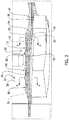
- Figure 2 is a representation of a partial elevation view of the joint 18 of this disclosure that joins the aircraft wing 14 to the aircraft body 12. Only a small portion of the entire longitudinal length of the aircraft body 12 is represented in Figure 2 . Additionally, only the longitudinal length of the wing box of the root of the aircraft wing that is attached to the aircraft body 12 is represented in Figure 2 .
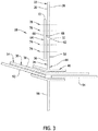
- Figure 3 is a schematic representation of a cross-section view through the joint 18 in a plane positioned along the line 3-3 of Figure 2 .
- Figure 4 is a schematic representation of a cross-section view through the joint 18 in a plane positioned along the line 4-4 of Figure 2 . Referring to Figures 1 and 2 , the construction of the joint 18 joins the aircraft wing 14 to the aircraft body 12. More specifically, the joint 18 joins a skin panel 22 on a side of the aircraft body 12 to an upstanding leg panel 24 extending upwardly from the aircraft wing 14.
- the skin panel 22 is represented schematically.
- the skin panel 22 is an external, fuselage skin panel on a side of the aircraft body 12.
- the construction of the skin panel 22 is conventional.
- the skin panel 22 is constructed of multiple layers of composite material sheets such as carbon fiber reinforced composite material fabric, carbon fiber reinforced composite material tapes, or a combination of these composite materials.
- the skin panel 22 could also be constructed of metallic materials such as aluminum or titanium.
- the skin panel 22 could have other equivalent constructions.
- the skin panel 22 represented in Figures 3 and 4 has an exterior surface 26 that is directed toward an exterior of the aircraft body 12 and an exterior environment of the aircraft body 12.
- the skin panel 22 has an interior surface 28 that is opposite the exterior surface 26 of the skin panel.
- the interior surface 28 of the skin panel 22 is directed toward an interior of the aircraft body 12.
- the interior surface 28 is not necessarily directed toward the interior of an aircraft cabin inside the aircraft body 12, but is directed toward the interior of the fuselage construction of the aircraft body 12.
- the skin panel 22 has a bottom edge defined by a bottom edge surface 32 of the skin panel that extends between the exterior surface 26 of the skin panel and the interior surface 28 of the skin panel.
- the bottom edge surface 32 is represented as a flat, planar surface in Figures 3 and 4 . However, the bottom edge surface 32 could be a swarf surface or other equivalent surface configuration.
- the aircraft wing 14 has a wing upper skin splice plate 34.
- the wing upper skin splice plate 34 has a conventional construction.
- the wing upper skin splice plate 34 is constructed of metallic materials, such as aluminum or titanium, or equivalent materials.
- the layer of metallic material 36 defines the top surface 38 of the aircraft wing 14.
- the aircraft wing 14 also has a bottom surface 42 opposite the top surface 38 as represented in Figure 2 .
- the bottom surface 42 could also have a skin construction similar to that of the top surface of the aircraft wing 38.
- the aircraft wing 14 is constructed with an over wing T chord 44 on the top surface 38 of the aircraft wing.
- the over wing T chord 44 is represented schematically in Figures 3 and 4 .
- the over wing T chord 44 extends along a portion of the longitudinal length of the aircraft wing 14.
- the over wing T chord 44 could extend along the entire longitudinal length of the aircraft wing 14.
- the over wing T chord 44 has a lower flange 46 that is secured to the top surface 38 of the aircraft wing 14.
- the over wing T chord 44 also includes the upstanding leg panel 24 that extends upwardly from the lower flange 46 of the T chord 44 and upwardly from the aircraft wing 14.
- the upstanding leg panel 24 has a longitudinal length that extends from a forward end edge 52 of the leg panel to a rearward end edge 54 of the leg panel.
- the over wing T chord 44 including the lower flange 46 and the upstanding leg panel 24 is constructed of a metallic material, such as titanium, aluminum, or other equivalent material.
- the leg panel 24 has an exterior surface 56 directed toward the exterior of the aircraft body 12 and toward an exterior environment of the aircraft body 12 and an opposite interior surface 56 directed toward the interior of the aircraft body 12.
- the interior surface 58 of the leg panel 24 is not necessarily directed toward the interior of the aircraft cabin of the aircraft body 12, but is directed toward the interior of the fuselage construction of the aircraft body 12.
- the leg panel 24 also has a top edge defined by a top edge surface 62 of the leg panel 24 that extends between the forward end edge 52 of the leg panel 24 and the rearward end edge 54 of the leg panel, and extends between the exterior surface 56 of the leg panel 24 and the interior surface 58 of the leg panel 24.
- the top edge surface 62 is represented as a flat, planar surface in Figures 3 and 4 . However, the top edge surface 62 could be a curved surface or other equivalent surface configuration.
- a splice panel 64 is used in forming the joint 18 joining the aircraft wing 14 to the aircraft body 12.
- the splice panel 64 is represented schematically.
- the splice panel 64 is constructed of composite material or metallic material, such as aluminum or ttanium.
- the splice panel 64 is constructed of multiple layers of composite material sheets such as carbon fiber reinforced composite fabric, carbon fiber reinforced composite tapes, or a combination of these composite materials or other equivalent materials.
- the splice panel 64 represented in Figures 3 and 4 has an exterior surface 66 that is directed toward an exterior of the aircraft body 12 and an exterior environment of the aircraft 12.
- the splice panel 64 has an interior surface 68 that is opposite the exterior surface 66 of the splice panel.
- the interior surface 68 of the splice panel 64 is directed toward an interior of the aircraft body 12.
- the interior surface 68 is not necessarily directed toward the interior of an aircraft cabin inside the aircraft body 12, but is directed toward the interior of the fuselage construction of the aircraft body 12.
- a peripheral edge surface 72 of the splice panel 64 extends completely around the splice panel and extends between the exterior surface 66 of the splice panel and the interior surface 68 of the splice panel.
- the interior surface 68 of the splice panel 64 is configured to engage in surface engagement with the exterior surface 56 of the leg panel 24 and the exterior surface 26 of the skin panel 22 in constructing the joint that joins the leg panel 24 to the skin panel 22.
- the splice panel 64 is used in constructing the joint 18 attaching the aircraft wing 14 to the aircraft body 12.
- the leg panel 24 extending upwardly from the top surface 38 of the aircraft wing 14 is positioned vertically adjacent the skin panel 22 on the fuselage of the aircraft body 12.
- the bottom edge surface 32 of the skin panel 22 is positioned directly opposite and above the top edge surface 62 of the leg panel 24 maintaining a gap between the bottom edge surface 32 and the top edge surface 62 of the leg panel 24.
- the splice panel 64 is attached to the leg panel 24 and the skin panel 22 by a plurality of fasteners, with the plurality of fasteners attaching the splice panel 64 to the leg panel 24 and attaching the splice panel 64 to the skin panel 22 and thereby attaching the leg panel 24 to the skin panel 22.
- a lower half of the interior surface 68 of the splice panel 64 is positioned in surface engagement with the exterior surface 56 of the leg panel 24.
- the splice panel 64 is held in this position relative to the leg panel 24 by mechanical clamps or other equivalent tools.
- Lower pairs of vertically spaced fastener holes 74 are then drilled through the splice panel 64 and the leg panel 24. These lower pairs of vertically spaced fastener holes 74 are represented schematically in Figures 3 and 4 . The lower pairs of vertically spaced fastener holes 74 are drilled through the splice panel 64 and the leg panel 24 at longitudinally spaced positions along the longitudinal lengths of the splice panel 64 and the leg panel 24.
- fasteners such as threaded bolt and threaded nut fasteners 76, or other equivalent fasteners, can be inserted through the drilled holes and tightened in the drilled holes to further hold the splice panel 64 to the leg panel 24.
- any fasteners 76 secured through the drilled holes are removed and the mechanical clamps holding the splice panel 64 and the leg panel 24 together are removed.
- the splice panel 64 is removed from the leg panel 24. With the splice panel 64 removed from the leg panel 24, the lower pairs of vertically spaced fastener holes 74 through the leg panel 24 are easily accessed.
- the lower pairs of vertically spaced fastener holes 74 drilled through the leg panel 24 are deburred using a deburring tool.
- the entrance edges of the lower pairs of vertically spaced fastener holes 74 are deburred and the exit edges of the lower pairs of vertically spaced fastener holes 74 are deburred.
- the notches formed by the burrs, particular at the exit edges of the lower pairs of vertically spaced fastener holes 74 through the leg panel 24 are removed by the deburring tool. This removes any potential starting point of a crack formed in the metallic material of the leg panel 24.
- the exit holes of the fastener holes 74 drilled through the splice panel 64 if made from a metallic material such as aluminum or titanium could also be deburred.
- the lower half of the interior surface 68 of the splice panel 64 is then positioned in surface engagement with the exterior surface 56 of the leg panel 24 with the previously drilled lower pairs of vertically spaced fastener holes 74 through both panels aligned.
- the lower pairs of threaded fasteners 76 are then inserted through the aligned lower pairs of vertically spaced fastener holes 74 of the splice panel 64 and the leg panel 24.
- the lower pairs of fasteners 76 are tightened down, attaching the splice panel 64 to the leg panel 24.
- the skin panel 22 on the side of the fuselage of the aircraft body 12 is then positioned above the leg panel 24.
- the bottom edge surface 32 of the skin panel 22 is positioned directly opposite and above the top edge surface 62 of the leg panel 24 as represented in Figures 3 and 4 .
- a portion of the exterior surface 26 of the skin panel 22 is positioned in surface engagement with the upper half of the interior surface 68 of the splice panel 64.
- the splice panel 64 and the skin panel 22 are then held together with mechanical clamps or other equivalent tools.
- Upper pairs of vertically spaced fastener holes 78 are then drilled through the splice panel 64 and the skin panel 22.
- the upper pairs of vertically spaced fastener holes 78 are represented schematically in Figures 3 and 4 .
- the upper pairs of vertically spaced fastener holes 78 are drilled through the splice panel 64 and the skin panel 22 at longitudinally spaced positions that are vertically aligned with the lower pairs of vertically spaced fastener holes 74 and the lower pairs of fasteners 76 that attach the splice panel 64 to the leg panel 24.
- upper pairs of vertically spaced fastener holes 78 are drilled at the longitudinally spaced positions, upper pairs of fasteners 82 such as threaded bolts and nuts can be inserted through the upper pairs of vertically spaced fastener holes 78 and tightened down to further hold the splice panel 64 to the skin panel 22.
- upper pairs of fasteners 82 such as threaded bolts and nuts can be inserted through the upper pairs of vertically spaced fastener holes 78 and tightened down to further hold the splice panel 64 to the skin panel 22.
- the upper pairs of threaded fasteners 82 are inserted through the aligned holes of the splice panel 64 and the skin panel 22.
- the upper pairs of threaded fasteners 82 are tightened down, attaching the splice panel 64 to the skin panel 22.
- the pluralities of fasteners 76 extending through the splice panel 64 and the leg panel 24 and the plurality of fasteners 82 extending through the splice panel 64 and the skin panel 22 attach the splice panel 64 to the leg panel 24 and the skin panel 22 and thereby attach the skin panel 22 to the leg panel 24.
- the mechanical clamps holding the splice panel 64 and the skin panel 22 together are then removed, completing the attachment of the skin panel 22 to the leg panel 24 by the splice panel 64.
- the lower pairs of vertically spaced fastener holes 74 drilled through the splice panel 64 and the leg panel 24 and the upper pairs of vertically spaced fastener holes 78 drilled through the splice panel 64 and the skin panel 22 can also extend into a vertically oriented column 84 of the fuselage frame.
- the lower pairs of fasteners 76 and the upper pairs of fasteners 82 that secure the splice panel 64 to the leg panel 24 and the skin panel 22 also secure the splice panel 64 to the column of the fuselage frame 84.
- the column of the fuselage frame 84 is constructed of a composite material or a metallic material such as aluminum or titanium.
- the splice panel 64 could first be attached to the skin panel 22 in the manner discussed above, and then the splice panel 64 could be attached to the leg panel 24, thereby attaching the skin panel 22 to the leg panel 24.
- Other equivalent sequences of attaching the skin panel 22 to the leg panel 24 using the splice panel 64 could also be employed in attaching the leg panel 24 to the skin panel 22.
- the splice panel 64 securing the leg panel 24 to the skin panel 22 is a first splice panel.
- a second splice panel 86 that is attached to the leg panel 24 and the skin panel 22 in the same manner as the first splice panel 64 described above.
- the first splice panel 64 and the second splice panel 86 function to join the aircraft wing 14 to the aircraft body 12.
- wing outboard upper skin 92 Also represented schematically in Figures 3 and 4 is a wing outboard upper skin 92, a wing inboard upper skin 94, and a Side-of-Body wing Rib 96.
Landscapes
- Engineering & Computer Science (AREA)
- Aviation & Aerospace Engineering (AREA)
- Mechanical Engineering (AREA)
- Manufacturing & Machinery (AREA)
- Transportation (AREA)
- Connection Of Plates (AREA)
- Joining Of Building Structures In Genera (AREA)
Abstract
Description
- This disclosure pertains to the construction of a joint joining portions of an aircraft. More specifically, this disclosure pertains to the construction of a joint that is one of the main connections between an aircraft wing and a fuselage of an aircraft body.
- In the construction of modern aircraft it is often necessary to attach together structural panels constructed of different materials. For example, it is often necessary to attach a structural panel of composite material to a structural panel of metallic material, for example aluminum or titanium.
- In attaching together large structural components of an aircraft, for example in attaching an aircraft wing to an aircraft body, one or more lap splices may be used as part of the construction attaching the aircraft wing to the aircraft body. In one example of attaching an aircraft wing to an aircraft body, an upstanding leg panel or a leg panel extending upwardly from the aircraft wing is overlapped with a skin panel on a side of the aircraft body. The overlapped leg panel and skin panel are then drilled through, preparing holes for fasteners to be inserted through the holes to secure the leg panel to the skin panel. In this example, an upstanding leg panel of an overwing T chord, which is typically constructed of a metallic material, is overlapped with a skin panel of the fuselage of the aircraft body, which is typically constructed of a composite or aluminum material. The holes for the fasteners used in attaching the leg panel to the skin panel are drilled through the leg panel overlapping the skin panel.
- Drilling the fastener holes through the metallic material of the leg panel often results in burrs being formed at the edge of the entry of the fastener hole drilled through the leg panel and at the edge of the exit of the fastener hole drilled through the leg panel. A burr or burrs are more often created at the exit edge of the fastener hole drilled through the metallic material of the leg panel. A burr is a small, raised or projecting edge or point of the metallic material at the exit edge of the drilled hole.
- The burrs created at the exit edge of the fastener hole function as a notch formed at the exit edge. The notch formed by the burr at the exit edge of the fastener hole can be a starting point of a crack formed in the metallic material of the leg panel. Thus, the notch formed by a burr at an exit edge of a fastener hole creates a fatigue critical region in a joint and the notch must be removed.
- In order to remove the burrs from the exit edge of the fastener hole drilled through the leg panel, and possibly also from the entry edge of the fastener hole, the edge of the fastener hole must be accessed by a deburring tool. The deburring tool machines around the edge of the fastener hole and basically forms the edge of the fastener hole as a chamfered surface or a beveled edge surface around the opening of the fastener hole. This eliminates any potential crack forming in the metallic material of the leg panel at the edge of the fastener hole. However, it is often difficult to access the exit edge of the fastener hole with the deburring tool.
- In the assembly of the aircraft, and in particular in joining an aircraft wing to an aircraft body, with the leg panel of the aircraft wing overlapping the skin panel of the aircraft body, it is often necessary to pry the overlapping panels apart. The overlapping panels are pried apart with a wedge, or a lever or other similar tool in order to gain access between the overlapping panels and gain access to the exit edge of the fastener hole. Prying the overlapping leg panel and skin panel apart to gain access to the exit edge of the fastener hole is a time consuming process. With there being many fastener holes drilled through the leg panel and the skin panel, prying the leg panel and the skin panel apart at locations of the many fastener holes adds significantly to the construction time of the aircraft and the cost of constructing the aircraft.
- The joint joining an aircraft wing to an aircraft body of this disclosure avoids the increase in production time and increase in production cost associated with removing burrs from an exit edge of a fastener hole drilled through a metallic panel. This is accomplished by simplifying the access to the exit edge of the fastener hole. This reduces the time required to access the exit edge of the fastener hole to remove burrs from the exit edge of the fastener hole, and thereby reduces production time and production cost.
- The construction of the joint of this disclosure joins a skin panel on a side of the aircraft body to a leg panel extending upwardly from the aircraft wing.
- The skin panel is an external, fuselage skin panel on a side of the aircraft body. The skin panel is constructed of a composite or a metallic material. The skin panel has an exterior surface that is directed toward an exterior of the aircraft body and an opposite interior surface that is directed toward an interior of the aircraft body. The skin panel has a bottom edge surface that extends between the exterior surface of the skin panel and the interior surface of the skin panel.
- The aircraft wing has a top surface and an opposite bottom surface. The aircraft wing is constructed with an over wing T chord located at the Side-of-Body Rib on the top surface of the aircraft wing. An upstanding leg panel of the T chord extends upwardly from the T chord.
- The leg panel extends upwardly from the top surface of the aircraft wing. The leg panel is constructed of a metallic material, such as titanium, aluminum or other equivalent material. The leg panel has an exterior surface directed toward the exterior of the aircraft body and an opposite interior surface directed toward the interior of the aircraft body. The leg panel has a top edge surface that extends between the exterior surface of the leg panel and the interior surface of the leg panel.
- A splice panel is used in joining the aircraft wing to the aircraft body. The splice panel is constructed of a composite material or metallic material such as aluminum or titanium. The splice panel has an exterior surface and an opposite interior surface. The interior surface of the splice panel engages in surface engagement with the exterior surface of the leg panel and engages in surface engagement with the exterior surface of the skin panel. In joining the aircraft wing to the aircraft body, the skin panel and the leg panel are positioned in a single vertically oriented plane. The bottom edge surface of the skin panel is positioned directly opposite the top edge surface of the leg panel with a gap between the bottom edge surface and top edge surface. The splice panel is then attached to the leg panel and the skin panel.
- In attaching the splice panel to the leg panel and the skin panel, prior to the skin panel being positioned above the leg panel, a lower half of the interior surface of the splice panel is positioned in surface engagement with the exterior surface of the leg panel.
- Pairs of vertically spaced fastener holes are then drilled through the splice panel and the leg panel. The pairs of vertically spaced fastener holes are drilled through the splice panel and the leg panel at longitudinally spaced positions along the longitudinal lengths of the splice panel and the leg panel.
- The splice panel is removed from the leg panel. With the splice panel removed from the leg panel, the drilled holes through the leg panel are easily accessed.
- The drilled holes through the leg panel are then deburred using a deburring tool. The entrance edges of the holes are deburred and the exit edges of the holes are deburred. The exit holes of the splice panel, if made of a metallic material such as aluminum or titanium can also be deburred.
- The splice panel is then positioned in surface engagement with the leg panel with the previously drilled holes through both panels aligned. Threaded fasteners are then inserted through the aligned holes of the splice panel and the leg panel. The threaded fasteners are tightened down, attaching the splice panel to the leg panel.
- The skin panel of the aircraft fuselage is then positioned above the leg panel. As described earlier, the skin panel has an exterior surface and an opposite interior surface, and a bottom edge surface. The bottom edge surface of the skin panel is positioned above the top edge surface of the leg panel maintaining a gap between the bottom edge of the skin panel and the top edge of the leg panel, and the exterior surface of the skin panel is positioned in surface engagement with an upper half of the interior surface of the splice panel.
- Pairs of vertically spaced fastener holes are then drilled through the splice panel and the skin panel. The pairs of vertically spaced fastener holes are drilled through the splice panel and the skin panel at longitudinally spaced positions that are vertically aligned with the pairs of vertically spaced fasteners that attach the splice panel to the leg panel.
- Threaded fasteners are then inserted through the aligned holes of the splice panel and the skin panel. The threaded fasteners are tightened down, attaching the splice panel to the skin panel.
- The plurality of fasteners extending through the splice panel and the leg panel and extending through the splice panel and the skin panel attach the splice panel to the leg panel and attach the splice panel to the skin panel and thereby attach the leg panel to the skin panel.
- The features, functions, and advantages that have been discussed can be achieved independently in various embodiments or may be combined in yet other embodiments, further details of which can be seen with reference to the following description and drawings.
- Further, the disclosure comprises the following enumerated examples:
- Example 1. A joint 18 joining an
aircraft wing 14 to anaircraft body 12, the joint comprising:- an
aircraft body 12; - an
aircraft wing 14, the aircraft wing having atop surface 38 and anopposite bottom surface 42; - a
skin panel 22 on a side of theaircraft body 12, theskin panel 22 having anexterior surface 26 that is directed toward an exterior of theaircraft body 12 and an oppositeinterior surface 28 that is directed toward an interior of theaircraft body 12; - a
leg panel 24 extending upwardly from thetop surface 38 of theaircraft wing 14, theleg panel 24 having anexterior surface 56 directed toward the exterior of theaircraft body 12 and an oppositeinterior surface 58 directed toward the interior of theaircraft body 12; - a
splice panel 64, thesplice panel 64 having anexterior surface 66 and an oppositeinterior surface 68, theinterior surface 68 of thesplice panel 64 engaging in engagement with theexterior surface 56 of theleg panel 24 and engaging in engagement with theexterior surface 26 of theskin panel 22; and, - a plurality of
fasteners splice panel 64 and theleg panel 24 and extending through thesplice panel 64 and theskin panel 22, the plurality offasteners splice panel 64 to theleg panel 24 and attaching thesplice panel 66 to theskin panel 22 and thereby attaching theskin panel 22 to theleg panel 24.
- an
- Example 2. The joint 18 of example 1, further comprising:
theinterior surface 68 of thesplice panel 64 engaging in surface engagement with theexterior surface 56 of theleg panel 24 and theinterior surface 68 of thesplice panel 64 engaging in surface engagement with theexterior surface 26 of theskin panel 22. - Example 3. The joint 18 of examples 1-2, wherein:
theskin panel 22 and theleg panel 24 are positioned in a single vertically oriented plane. - Example 4. The joint 18 of examples 1-3, wherein:
- the
leg panel 24 has a top edge defined by atop edge surface 62 that extends between theexterior surface 56 of theleg panel 24 and theinterior surface 58 of theleg panel 24; - the
skin panel 22 has a bottom edge defined by abottom edge surface 32 that extends between theexterior surface 26 of theskin panel 22 and theinterior surface 28 of theskin panel 22; and, - the
bottom edge surface 32 of theskin panel 22 is positioned directly opposite and above thetop edge surface 62 of theleg panel 24.
- the
- Example 5. The joint 18 of examples 1-4, further comprising:
- the
splice panel 64 is a first splice panel having anexterior surface 66 directed away from theaircraft body 12 and an oppositeinterior surface 68, theinterior surface 68 of thefirst splice panel 64 engaging in engagement with theexterior surface 56 of theleg panel 24 and engaging in engagement with theexterior surface 26 of theskin panel 22; - a
second splice panel 86, thesecond splice panel 86 having an exterior surface directed away from theaircraft body 12 and an opposite interior surface, the interior surface of thesecond splice panel 86 engaging in engagement with theexterior surface 56 of theleg panel 24 and engaging in engagement with theexterior surface 26 of theskin panel 22; and, - the plurality of
fasteners first splice panel 64 and theleg panel 24 and extending through thefirst splice panel 64 and theskin panel 22, the plurality offasteners second splice panel 86 and theleg panel 24 and extending through thesecond splice panel 86 and theskin panel 22, the plurality offasteners first splice panel 64 and thesecond splice panel 86 to theleg panel 24 and theskin panel 22 and thereby attaching theskin panel 22 to theleg panel 24.
- the
- Example 6. The joint 18 of examples 1-5, further comprising:
the plurality offasteners splice panel 64 and theleg panel 24 and from extending through thesplice panel 64 and theskin panel 22 to detach thesplice panel 64 from theleg panel 24 and detach thesplice panel 64 from theskin panel 22. - Example 7. The joint 18 of examples 1-6, wherein:
- the
leg panel 24 is constructed of one of a metallic material and a composite material; - the
skin panel 22 is constructed of one of a metallic material and a composite material; and, - the
splice panel 64 is constructed of one of a metallic material and a composite material.
- the
- Example 8. The joint 18 of examples 1-7, wherein:
theskin panel 22 is an external, fuselage skin panel. - Example 9. The joint 18 of examples 1-8, further comprising:
the plurality offasteners upper fasteners 82 extending through thesplice panel 64 and theskin panel 22 and pairs of vertically spacedlower fasteners 76 extending through thesplice panel 64 and theleg panel 24. - Example 10. The joint 18 of example 9, wherein:
the pairs of vertically spacedupper fasteners 82 and the pairs of vertically spacedlower fasteners 76 are positioned in a single vertically oriented plane. - Example 11. A joint 18 joining an
aircraft wing 14 to anaircraft body 12, the joint comprising:- an
aircraft body 12; - an
aircraft wing 14, the aircraft wing having atop surface 38 and anopposite bottom surface 42; - a
skin panel 22 on a side of theaircraft body 12, theskin panel 22 having anexterior surface 26 that is directed toward an exterior of theaircraft body 12 and an oppositeinterior surface 28 that is directed toward an interior of theaircraft body 12; - a
leg panel 24 extending upwardly from thetop surface 38 of theaircraft wing 14, theleg panel 24 having anexterior surface 56 directed toward the exterior of theaircraft body 12 and an oppositeinterior surface 58 directed toward the interior of theaircraft body 12; - a
splice panel 64, thesplice panel 64 having anexterior surface 66 and an oppositeinterior surface 68, theinterior surface 68 of thesplice panel 64 engaging in engagement with theexterior surface 56 of theleg panel 24 and engaging in engagement with theexterior surface 26 of theskin panel 22; and, - a plurality of
fasteners splice panel 64 and theleg panel 24 and extending through thesplice panel 64 and theskin panel 22, the plurality offasteners splice panel 64 to theleg panel 24 and attaching thesplice panel 66 to theskin panel 22 and thereby attaching theskin panel 22 to theleg panel 24.
- an
- Example 12. The joint 18 of example 11, wherein:
theinterior surface 68 of thesplice panel 64 engaging in surface engagement with theexterior surface 56 of theleg panel 24 and theinterior surface 68 of thesplice panel 64 engaging in surface engagement with theexterior surface 26 of theskin panel 22. - Example 13. The joint 18 of example 11 or 12, wherein:
theskin panel 22 and theleg panel 24 are positioned in a single vertically oriented plane. - Example 14. The joint 18 of any of the examples 11-13 wherein:
- the
leg panel 24 has a top edge defined by atop edge surface 62 that extends between theexterior surface 56 of theleg panel 24 and theinterior surface 58 of theleg panel 24; - the
skin panel 22 has a bottom edge defined by abottom edge surface 32 that extends between theexterior surface 26 of theskin panel 22 and theinterior surface 28 of theskin panel 22; and, - the
bottom edge surface 32 of theskin panel 22 is positioned directly opposite and above thetop edge surface 62 of theleg panel 24.
- the
- Example 15. The joint 18 ofany of the examples 11-14 example 11, wherein:
- the
splice panel 64 is a first splice panel having anexterior surface 66 directed away from theaircraft body 12 and an oppositeinterior surface 68, theinterior surface 68 of thefirst splice panel 64 engaging in engagement with theexterior surface 56 of theleg panel 24 and engaging in engagement with theexterior surface 26 of theskin panel 22; - a
second splice panel 86, thesecond splice panel 86 having an exterior surface directed away from theaircraft body 12 and an opposite interior surface, the interior surface of thesecond splice panel 86 engaging in engagement with theexterior surface 56 of theleg panel 24 and engaging in engagement with theexterior surface 26 of theskin panel 22; and, - the plurality of
fasteners first splice panel 64 and theleg panel 24 and extending through thefirst splice panel 64 and theskin panel 22, the plurality offasteners second splice panel 86 and theleg panel 24 and extending through thesecond splice panel 86 and theskin panel 22, the plurality offasteners first splice panel 64 and thesecond splice panel 86 to theleg panel 24 and theskin panel 22 and thereby attaching theskin panel 22 to theleg panel 24.
- the
- Example 16. The joint 18 of any of the examples 11-15 wherein:
the plurality offasteners splice panel 64 and theleg panel 24 and from extending through thesplice panel 64 and theskin panel 22 to detach thesplice panel 64 from theleg panel 24 and detach thesplice panel 64 from theskin panel 22. - Example 17. The joint 18 of any of the examples 11-16 wherein:
- the
leg panel 24 is constructed of one of a metallic material and a composite material; - the
skin panel 22 is constructed of one of a metallic material and a composite material; and, - the
splice panel 64 is constructed of one of a metallic material and a composite material.
- the
- Example 18. The joint 18 of any of the examples 11-17 wherein:
theskin panel 22 is an external, fuselage skin panel. - Example 19. A method of joining an
aircraft wing 14 to anaircraft body 12, the method comprising:- positioning a
skin panel 22 on a side of anaircraft body 12 directly opposite and above aleg panel 24 extending upwardly from anaircraft wing 14; - positioning a
splice panel 64 in engagement with theleg panel 24 and in engagement with theskin panel 22; and, - positioning a plurality of
fasteners splice panel 64 and theleg panel 24 and extending through thesplice panel 64 and theskin panel 22 with the plurality offasteners splice panel 64 to theleg panel 24 and attaching thesplice panel 64 to theskin panel 22.
- positioning a
- Example 20. The method of example 19, wherein:
- positioning a
bottom edge 32 of theskin panel 22 directly opposite and above atop edge 62 of theleg panel 24; - positioning the
splice panel 64 in engagement with theleg panel 24 and in engagement with theskin panel 22 over thebottom edge 32 of theskin panel 22 and over thetop edge 62 of theleg panel 24; and, - positioning the plurality of
fasteners splice panel 64 and theleg panel 24 and extending through thesplice panel 64 and theskin panel 22 with the plurality offasteners splice panel 64 to theleg panel 24 and attaching thesplice panel 64 to theskin panel 22 over thebottom edge 32 of theskin panel 22 and over thetop edge 62 of theleg panel 24.
- positioning a
- Example 21: A joint 18 for joining an aircraft wing to an aircraft body, the joint comprising:
- a
skin panel 22, for anaircraft body 12; - a
leg panel 24 for anaircraft wing 14; - a
splice panel 64 attached to theleg panel 24 and attached to theskin panel 22; and, - a plurality of
fasteners splice panel 64 and theleg panel 24 and extending through thesplice panel 64 and theskin panel 22, the plurality offasteners splice panel 64 to theleg panel 24 and attaching thesplice panel 64 to theskin panel 22.
- a
-
-
Figure 1 is a representation of a perspective view of an aircraft and the position of the joint of this disclosure on the aircraft body and aircraft wing of the aircraft. -
Figure 2 is a side elevation view of the joint of this disclosure on the aircraft body and aircraft wing ofFigure 1 . -
Figure 3 is a schematic representation of a cross-section view through the joint ofFigure 2 in a plane along the line 3-3 ofFigure 2 . -
Figure 4 is a schematic representation of a cross-section view through the joint ofFigure 2 in a plane along the line 4-4 ofFigure 2 . -
Figure 5 is a representation of a perspective view of the joint ofFigure 1 . -
Figure 1 is a representation of a perspective view of anaircraft body 12 andaircraft wings aircraft body 12. The joint of this disclosure that joins theaircraft wings aircraft body 12 is positioned relative to theaircraft body 12 on the left side, or portside aircraft wing 14 in the area of therectangle 2 represented inFigure 1 . It should be understood that the joint of this disclosure would also join the right side or starboardside aircraft wing 16 to theaircraft body 12. The joint of this disclosure connecting the port side or leftside aircraft wing 14 to theaircraft body 12 will be disclosed herein, with it understood that the joint of this disclosure would also join the right side or starboardside aircraft wing 16 to theaircraft body 12. -
Figure 2 is a representation of a partial elevation view of the joint 18 of this disclosure that joins theaircraft wing 14 to theaircraft body 12. Only a small portion of the entire longitudinal length of theaircraft body 12 is represented inFigure 2 . Additionally, only the longitudinal length of the wing box of the root of the aircraft wing that is attached to theaircraft body 12 is represented inFigure 2 .Figure 3 is a schematic representation of a cross-section view through the joint 18 in a plane positioned along the line 3-3 ofFigure 2 .Figure 4 is a schematic representation of a cross-section view through the joint 18 in a plane positioned along the line 4-4 ofFigure 2 . Referring toFigures 1 and2 , the construction of the joint 18 joins theaircraft wing 14 to theaircraft body 12. More specifically, the joint 18 joins askin panel 22 on a side of theaircraft body 12 to anupstanding leg panel 24 extending upwardly from theaircraft wing 14. - Referring to
Figures 3 and4 , theskin panel 22 is represented schematically. Theskin panel 22 is an external, fuselage skin panel on a side of theaircraft body 12. The construction of theskin panel 22 is conventional. For example, theskin panel 22 is constructed of multiple layers of composite material sheets such as carbon fiber reinforced composite material fabric, carbon fiber reinforced composite material tapes, or a combination of these composite materials. Theskin panel 22 could also be constructed of metallic materials such as aluminum or titanium. Theskin panel 22 could have other equivalent constructions. Theskin panel 22 represented inFigures 3 and4 has anexterior surface 26 that is directed toward an exterior of theaircraft body 12 and an exterior environment of theaircraft body 12. Theskin panel 22 has aninterior surface 28 that is opposite theexterior surface 26 of the skin panel. Theinterior surface 28 of theskin panel 22 is directed toward an interior of theaircraft body 12. Theinterior surface 28 is not necessarily directed toward the interior of an aircraft cabin inside theaircraft body 12, but is directed toward the interior of the fuselage construction of theaircraft body 12. Theskin panel 22 has a bottom edge defined by abottom edge surface 32 of the skin panel that extends between theexterior surface 26 of the skin panel and theinterior surface 28 of the skin panel. Thebottom edge surface 32 is represented as a flat, planar surface inFigures 3 and4 . However, thebottom edge surface 32 could be a swarf surface or other equivalent surface configuration. - The
aircraft wing 14 has a wing upperskin splice plate 34. The wing upperskin splice plate 34 has a conventional construction. For example, the wing upperskin splice plate 34 is constructed of metallic materials, such as aluminum or titanium, or equivalent materials. The layer ofmetallic material 36 defines thetop surface 38 of theaircraft wing 14. Theaircraft wing 14 also has abottom surface 42 opposite thetop surface 38 as represented inFigure 2 . Thebottom surface 42 could also have a skin construction similar to that of the top surface of theaircraft wing 38. - As represented in
Figures 3 and4 , theaircraft wing 14 is constructed with an overwing T chord 44 on thetop surface 38 of the aircraft wing. The overwing T chord 44 is represented schematically inFigures 3 and4 . The overwing T chord 44 extends along a portion of the longitudinal length of theaircraft wing 14. The overwing T chord 44 could extend along the entire longitudinal length of theaircraft wing 14. The overwing T chord 44 has alower flange 46 that is secured to thetop surface 38 of theaircraft wing 14. The overwing T chord 44 also includes theupstanding leg panel 24 that extends upwardly from thelower flange 46 of theT chord 44 and upwardly from theaircraft wing 14. As represented inFigure 2 , theupstanding leg panel 24 has a longitudinal length that extends from aforward end edge 52 of the leg panel to arearward end edge 54 of the leg panel. The overwing T chord 44 including thelower flange 46 and theupstanding leg panel 24 is constructed of a metallic material, such as titanium, aluminum, or other equivalent material. Theleg panel 24 has anexterior surface 56 directed toward the exterior of theaircraft body 12 and toward an exterior environment of theaircraft body 12 and an oppositeinterior surface 56 directed toward the interior of theaircraft body 12. Theinterior surface 58 of theleg panel 24 is not necessarily directed toward the interior of the aircraft cabin of theaircraft body 12, but is directed toward the interior of the fuselage construction of theaircraft body 12. Theleg panel 24 also has a top edge defined by atop edge surface 62 of theleg panel 24 that extends between theforward end edge 52 of theleg panel 24 and therearward end edge 54 of the leg panel, and extends between theexterior surface 56 of theleg panel 24 and theinterior surface 58 of theleg panel 24. Thetop edge surface 62 is represented as a flat, planar surface inFigures 3 and4 . However, thetop edge surface 62 could be a curved surface or other equivalent surface configuration. - A
splice panel 64 is used in forming the joint 18 joining theaircraft wing 14 to theaircraft body 12. Referring toFigures 3 and4 , thesplice panel 64 is represented schematically. Thesplice panel 64 is constructed of composite material or metallic material, such as aluminum or ttanium. For example, thesplice panel 64 is constructed of multiple layers of composite material sheets such as carbon fiber reinforced composite fabric, carbon fiber reinforced composite tapes, or a combination of these composite materials or other equivalent materials. - The
splice panel 64 represented inFigures 3 and4 has anexterior surface 66 that is directed toward an exterior of theaircraft body 12 and an exterior environment of theaircraft 12. Thesplice panel 64 has aninterior surface 68 that is opposite theexterior surface 66 of the splice panel. Theinterior surface 68 of thesplice panel 64 is directed toward an interior of theaircraft body 12. Theinterior surface 68 is not necessarily directed toward the interior of an aircraft cabin inside theaircraft body 12, but is directed toward the interior of the fuselage construction of theaircraft body 12. Aperipheral edge surface 72 of thesplice panel 64 extends completely around the splice panel and extends between theexterior surface 66 of the splice panel and theinterior surface 68 of the splice panel. Theinterior surface 68 of thesplice panel 64 is configured to engage in surface engagement with theexterior surface 56 of theleg panel 24 and theexterior surface 26 of theskin panel 22 in constructing the joint that joins theleg panel 24 to theskin panel 22. - The
splice panel 64 is used in constructing the joint 18 attaching theaircraft wing 14 to theaircraft body 12. In the construction of the joint 18 joining theaircraft wing 14 to theaircraft body 12, theleg panel 24 extending upwardly from thetop surface 38 of theaircraft wing 14 is positioned vertically adjacent theskin panel 22 on the fuselage of theaircraft body 12. Thebottom edge surface 32 of theskin panel 22 is positioned directly opposite and above thetop edge surface 62 of theleg panel 24 maintaining a gap between thebottom edge surface 32 and thetop edge surface 62 of theleg panel 24. Thesplice panel 64 is attached to theleg panel 24 and theskin panel 22 by a plurality of fasteners, with the plurality of fasteners attaching thesplice panel 64 to theleg panel 24 and attaching thesplice panel 64 to theskin panel 22 and thereby attaching theleg panel 24 to theskin panel 22. - In attaching the
splice panel 64 to theleg panel 24, prior to theskin panel 22 and theleg panel 24 being positioned in a single vertically oriented plane with theskin panel 22 positioned directly above theleg panel 24, a lower half of theinterior surface 68 of thesplice panel 64 is positioned in surface engagement with theexterior surface 56 of theleg panel 24. Thesplice panel 64 is held in this position relative to theleg panel 24 by mechanical clamps or other equivalent tools. - Lower pairs of vertically spaced fastener holes 74 are then drilled through the
splice panel 64 and theleg panel 24. These lower pairs of vertically spaced fastener holes 74 are represented schematically inFigures 3 and4 . The lower pairs of vertically spaced fastener holes 74 are drilled through thesplice panel 64 and theleg panel 24 at longitudinally spaced positions along the longitudinal lengths of thesplice panel 64 and theleg panel 24. As the pairs of vertically spaced fastener holes 74 are drilled through thesplice panel 64 and theleg panel 24 along the longitudinal lengths of thesplice panel 64 and theleg panel 24, fasteners such as threaded bolt and threadednut fasteners 76, or other equivalent fasteners, can be inserted through the drilled holes and tightened in the drilled holes to further hold thesplice panel 64 to theleg panel 24. - When the process of drilling the lower pairs of vertically spaced fastener holes 74 through the
splice panel 64 and theleg panel 24 is complete, anyfasteners 76 secured through the drilled holes are removed and the mechanical clamps holding thesplice panel 64 and theleg panel 24 together are removed. Thesplice panel 64 is removed from theleg panel 24. With thesplice panel 64 removed from theleg panel 24, the lower pairs of vertically spaced fastener holes 74 through theleg panel 24 are easily accessed. - With the
splice panel 64 removed from theleg panel 24, the lower pairs of vertically spaced fastener holes 74 drilled through theleg panel 24 are deburred using a deburring tool. The entrance edges of the lower pairs of vertically spaced fastener holes 74 are deburred and the exit edges of the lower pairs of vertically spaced fastener holes 74 are deburred. The notches formed by the burrs, particular at the exit edges of the lower pairs of vertically spaced fastener holes 74 through theleg panel 24 are removed by the deburring tool. This removes any potential starting point of a crack formed in the metallic material of theleg panel 24. The exit holes of the fastener holes 74 drilled through thesplice panel 64, if made from a metallic material such as aluminum or titanium could also be deburred. - The lower half of the
interior surface 68 of thesplice panel 64 is then positioned in surface engagement with theexterior surface 56 of theleg panel 24 with the previously drilled lower pairs of vertically spaced fastener holes 74 through both panels aligned. The lower pairs of threadedfasteners 76 are then inserted through the aligned lower pairs of vertically spaced fastener holes 74 of thesplice panel 64 and theleg panel 24. The lower pairs offasteners 76 are tightened down, attaching thesplice panel 64 to theleg panel 24. - The
skin panel 22 on the side of the fuselage of theaircraft body 12 is then positioned above theleg panel 24. Thebottom edge surface 32 of theskin panel 22 is positioned directly opposite and above thetop edge surface 62 of theleg panel 24 as represented inFigures 3 and4 . A portion of theexterior surface 26 of theskin panel 22 is positioned in surface engagement with the upper half of theinterior surface 68 of thesplice panel 64. Thesplice panel 64 and theskin panel 22 are then held together with mechanical clamps or other equivalent tools. - Upper pairs of vertically spaced fastener holes 78 are then drilled through the
splice panel 64 and theskin panel 22. The upper pairs of vertically spaced fastener holes 78 are represented schematically inFigures 3 and4 . The upper pairs of vertically spaced fastener holes 78 are drilled through thesplice panel 64 and theskin panel 22 at longitudinally spaced positions that are vertically aligned with the lower pairs of vertically spaced fastener holes 74 and the lower pairs offasteners 76 that attach thesplice panel 64 to theleg panel 24. As the upper pairs of vertically spaced fastener holes 78 are drilled at the longitudinally spaced positions, upper pairs offasteners 82 such as threaded bolts and nuts can be inserted through the upper pairs of vertically spaced fastener holes 78 and tightened down to further hold thesplice panel 64 to theskin panel 22. - When drilling the upper pairs of vertically spaced fastener holes 78 through the
splice panel 64 and theskin panel 22 is complete, the upper pairs of threadedfasteners 82 are inserted through the aligned holes of thesplice panel 64 and theskin panel 22. The upper pairs of threadedfasteners 82 are tightened down, attaching thesplice panel 64 to theskin panel 22. The pluralities offasteners 76 extending through thesplice panel 64 and theleg panel 24 and the plurality offasteners 82 extending through thesplice panel 64 and theskin panel 22 attach thesplice panel 64 to theleg panel 24 and theskin panel 22 and thereby attach theskin panel 22 to theleg panel 24. - The mechanical clamps holding the
splice panel 64 and theskin panel 22 together are then removed, completing the attachment of theskin panel 22 to theleg panel 24 by thesplice panel 64. - Referring to the schematic representation of
Figure 4 , the lower pairs of vertically spaced fastener holes 74 drilled through thesplice panel 64 and theleg panel 24 and the upper pairs of vertically spaced fastener holes 78 drilled through thesplice panel 64 and theskin panel 22 can also extend into a vertically orientedcolumn 84 of the fuselage frame. The lower pairs offasteners 76 and the upper pairs offasteners 82 that secure thesplice panel 64 to theleg panel 24 and theskin panel 22 also secure thesplice panel 64 to the column of thefuselage frame 84. The column of thefuselage frame 84 is constructed of a composite material or a metallic material such as aluminum or titanium. - As an alternative to the sequence of attaching the
splice panel 64 to theleg panel 24 and theskin panel 22 discussed above, thesplice panel 64 could first be attached to theskin panel 22 in the manner discussed above, and then thesplice panel 64 could be attached to theleg panel 24, thereby attaching theskin panel 22 to theleg panel 24. Other equivalent sequences of attaching theskin panel 22 to theleg panel 24 using thesplice panel 64 could also be employed in attaching theleg panel 24 to theskin panel 22. - Referring to
Figures 2 and5 , thesplice panel 64 securing theleg panel 24 to theskin panel 22 is a first splice panel. There could also be asecond splice panel 86 that is attached to theleg panel 24 and theskin panel 22 in the same manner as thefirst splice panel 64 described above. Together, thefirst splice panel 64 and thesecond splice panel 86 function to join theaircraft wing 14 to theaircraft body 12. There could also be a third splice panel or more splice panels used in the joint 18 joining theaircraft wing 14 to theaircraft body 12. - Also represented schematically in
Figures 3 and4 is a wing outboardupper skin 92, a wing inboardupper skin 94, and a Side-of-Body wing Rib 96. - As various modifications could be made in the construction of the joint joining an aircraft wing to an aircraft body and its method of use herein described and illustrated without departing from the scope of the invention, it is intended that all matter contained in the foregoing description or shown in the accompanying drawings shall be interpreted as illustrative rather than limiting. Thus, the breadth and scope of the present disclosure should not be limited by any of the above described exemplary embodiments, but should be defined only in accordance with the following claims appended hereto and their equivalents.
Claims (15)
- A joint (18) joining an aircraft wing (14) to an aircraft body (12), the joint (18) comprising:a skin panel (22) on a side of the aircraft body (12);a leg panel (24) extending upwardly from the aircraft wing (14);a splice panel (64) attached to the leg panel (24) and attached to the skin panel (22); anda plurality of fasteners (76, 82) extending through the splice panel (64) and the leg panel (24) and extending through the splice panel (64) and the skin panel (22), the plurality of fasteners (76, 82) attaching the splice panel (64) to the leg panel (24) and attaching the splice panel (64) to the skin panel (22).
- The joint (18) of claim 1, wherein:
the splice panel 64 engages in surface engagement with the leg panel 24 and engages in surface engagement with the skin panel 22. - The joint (18) of any of the claims 1-2, wherein:
the leg panel (24) and the skin panel (22) are positioned in a single vertically oriented plane. - The joint (18) of any of the claims 1-3, wherein:the leg panel (24) has a top edge (62);the skin panel (22) has a bottom edge (32); and,the bottom edge (32) of the skin panel (22) is positioned directly opposite and above the top edge (62) of the leg panel (24).
- The joint 18 of claims 1-4, wherein:the splice panel (64) is a first splice panel engaged in engagement with the leg panel (24) and engaged in engagement with the skin panel (22);a second splice panel (86) is engaged in engagement with the leg panel (24) and is engaged in engagement with the skin panel (22);the plurality of fasteners (76, 82) extend through the first splice panel (64) and the leg panel (24) and extend through the first splice panel (64) and the skin panel (22); and,the plurality of fasteners (76, 82) extend through the second splice panel (86) and the leg panel (24), and extend through the second splice panel (86) and the skin panel (22),the plurality of fasteners (76, 82) attach the first splice panel (64) to the leg panel (24) and attach the first splice panel (64) to the skin panel (22) and,the plurality of fasteners (76, 82) attach the second splice panel (86) to the leg panel (24) and attach the second splice panel (86) to the skin panel (22) and thereby attach the skin panel (22) to the leg panel (24).
- The joint (18) of claims 1-5, wherein:
the plurality of fasteners (76, 82) are removable from extending through the splice panel (64) and the leg panel (24) and from extending through the splice panel (64) and the skin panel (22) to detach the splice panel (64) from the leg panel (24) and detach the splice panel (64) from the skin panel (22). - The joint (18) of claims 1-6, with one or more of the following, wherein :the leg panel (24) is constructed of one of a metallic material and a composite material;the skin panel (22) is constructed of one of a metallic material and a composite material; and,the splice panel (64) is constructed of one of a metallic material and a composite material.
- The joint (18) of claims 1-7, wherein:
the skin panel (22) is an external, fuselage skin panel. - The joint 18 of claims 1-8, wherein:
the plurality of fasteners (76, 82) include pairs of vertically spaced upper fasteners (82) extending through the splice panel (64) and the skin panel (22) and pairs of vertically spaced lower fasteners (76) extending through the splice panel (64) and the leg panel (24). - The joint (18) of claim 9, wherein:
the pairs of vertically spaced upper fasteners (82) and the pairs of vertically spaced lower fasteners (76) are positioned in a single vertically oriented plane. - An aircraft comprising a joint (18) according to any of the preceding claims.
- A method of joining an aircraft wing (14) to an aircraft body (12), the method comprising:positioning a skin panel (22) on a side of an aircraft body (12) directly opposite and above a leg panel (24) extending upwardly from an aircraft wing (14);positioning a splice panel (64) in engagement with the leg panel (24) and in engagement with the skin panel (22); and,positioning a plurality of fasteners (76, 82) extending through the splice panel (64) and the leg panel (24) and extending through the splice panel (64) and the skin panel (22) with the plurality of fasteners (76, 82) attaching the splice panel (64) to the leg panel (24) and attaching the splice panel (64) to the skin panel (22).
- The method of claim 12, further comprising:positioning a bottom edge (32) of the skin panel (22) directly opposite and above a top edge (62) of the leg panel (24);positioning the splice panel (64) in engagement with the leg panel (24) and in engagement with the skin panel (22) over the bottom edge (32) of the skin panel (22) and over the top edge (62) of the leg panel (24); and,positioning the plurality of fasteners (76, 82) extending through the splice panel (64) and the leg panel (24) and extending through the splice panel (64) and the skin panel 22 with the plurality of fasteners (76, 82) attaching the splice panel (64) to the leg panel (24) and attaching the splice panel (64) to the skin panel (22) over the bottom edge (32) of the skin panel (22) and over the top edge (62) of the leg panel (24).
- Use of a joint according to any of the claims 1-10 in an aircraft.
- A joint (18) for joining an aircraft wing to an aircraft body, the joint comprising:a skin panel (22), for an aircraft body;a leg panel (24) for an aircraft wing;a splice panel (64) attached to the leg panel (24) and attached to the skin panel (22); anda plurality of fasteners (76, 82) extending through the splice panel (64) and the leg panel (24) and extending through the splice panel (64) and the skin panel (22), the plurality of fasteners (76, 82) attaching the splice panel (64) to the leg panel (24) and attaching the splice panel (64) to the skin panel (22).
Applications Claiming Priority (1)
| Application Number | Priority Date | Filing Date | Title |
|---|---|---|---|
| US16/722,186 US11305862B2 (en) | 2019-12-20 | 2019-12-20 | Joint joining an aircraft wing to an aircraft body |
Publications (2)
| Publication Number | Publication Date |
|---|---|
| EP3838742A1 true EP3838742A1 (en) | 2021-06-23 |
| EP3838742B1 EP3838742B1 (en) | 2026-04-08 |
Family
ID=73855895
Family Applications (1)
| Application Number | Title | Priority Date | Filing Date |
|---|---|---|---|
| EP20215650.1A Active EP3838742B1 (en) | 2019-12-20 | 2020-12-18 | Joint joining an aircraft wing to an aircraft body |
Country Status (4)
| Country | Link |
|---|---|
| US (1) | US11305862B2 (en) |
| EP (1) | EP3838742B1 (en) |
| JP (1) | JP7628814B2 (en) |
| CA (1) | CA3100811A1 (en) |
Citations (4)
| Publication number | Priority date | Publication date | Assignee | Title |
|---|---|---|---|---|
| US20050224655A1 (en) * | 2003-12-04 | 2005-10-13 | Dominique Guittard | Method for making a laminated structure and aircraft provided with such a structure |
| US20110147521A1 (en) * | 2009-07-16 | 2011-06-23 | Airbus Operations (S.A.S.) | Method of constructing a fixed-wing aircraft |
| US20120286090A1 (en) * | 2011-03-25 | 2012-11-15 | Airbus Operations (Societe Par Actions Simplifiee) | Connection of a fuselage to an aircraft wing |
| EP2824030A1 (en) * | 2013-07-10 | 2015-01-14 | The Boeing Company | Apparatus and methods for joining composite structures of aircrafts |
Family Cites Families (12)
| Publication number | Priority date | Publication date | Assignee | Title |
|---|---|---|---|---|
| FR1523404A (en) * | 1967-03-22 | 1968-05-03 | Sud Aviation | Improvement in the connections between the fuselage and the wing of an aerodyne |
| US5297760A (en) * | 1992-08-21 | 1994-03-29 | Mcdonnell Douglas Corporation | Aircraft skin lap splice |
| US6314630B1 (en) * | 1996-03-22 | 2001-11-13 | The Boeing Company | Determinant wing assembly |
| FR2873347B1 (en) * | 2004-07-22 | 2006-11-17 | Airbus France Sas | DEVICE FOR LAUNCHING ELEMENTS OF COMPOSITE STRUCTURE WITH METALLIC STRUCTURE ELEMENTS |
| DE102005038856A1 (en) * | 2005-08-17 | 2007-02-22 | Airbus Deutschland Gmbh | Fastening system for attaching tail unit at fastening surface of airplane, has contact surfaces for attachment at tail unit and fastening surface, where contact surfaces comprise contact line and differentiating angle of specified degrees |
| US20070051851A1 (en) * | 2005-09-02 | 2007-03-08 | The Boeing Company | Multi-piece fastener for limited clearance applications |
| DE102007019692B4 (en) * | 2007-04-26 | 2011-06-01 | Airbus Operations Gmbh | Wing-hull section of an airplane |
| ES2372849B1 (en) * | 2010-03-25 | 2012-12-13 | Airbus Operations, S.L. | STRUCTURE OF UNION OF TORSION DRAWERS IN AN AIRCRAFT THROUGH A TRIFORM HARDWARE OF NON-METAL COMPOSITE MATERIALS. |
| FR2970463B1 (en) * | 2011-01-17 | 2013-02-15 | Airbus Operations Sas | LIGHTING DEVICE WITH IMPROVED MECHANICAL STRENGTH. |
| US9227718B2 (en) * | 2013-06-07 | 2016-01-05 | The Boeing Company | Lower joints between outboard wing boxes and center wing sections of aircraft wing assemblies |
| US10479475B2 (en) * | 2013-08-09 | 2019-11-19 | The Boeing Company | Composite stringer beam joint structure of an aircraft |
| CN110406658B (en) * | 2019-08-08 | 2024-07-23 | 中国商用飞机有限责任公司北京民用飞机技术研究中心 | Wing fuselage attach fitting and aircraft |
-
2019
- 2019-12-20 US US16/722,186 patent/US11305862B2/en active Active
-
2020
- 2020-11-26 CA CA3100811A patent/CA3100811A1/en active Pending
- 2020-12-07 JP JP2020202660A patent/JP7628814B2/en active Active
- 2020-12-18 EP EP20215650.1A patent/EP3838742B1/en active Active
Patent Citations (4)
| Publication number | Priority date | Publication date | Assignee | Title |
|---|---|---|---|---|
| US20050224655A1 (en) * | 2003-12-04 | 2005-10-13 | Dominique Guittard | Method for making a laminated structure and aircraft provided with such a structure |
| US20110147521A1 (en) * | 2009-07-16 | 2011-06-23 | Airbus Operations (S.A.S.) | Method of constructing a fixed-wing aircraft |
| US20120286090A1 (en) * | 2011-03-25 | 2012-11-15 | Airbus Operations (Societe Par Actions Simplifiee) | Connection of a fuselage to an aircraft wing |
| EP2824030A1 (en) * | 2013-07-10 | 2015-01-14 | The Boeing Company | Apparatus and methods for joining composite structures of aircrafts |
Also Published As
| Publication number | Publication date |
|---|---|
| JP2021107213A (en) | 2021-07-29 |
| CA3100811A1 (en) | 2021-06-20 |
| EP3838742B1 (en) | 2026-04-08 |
| JP7628814B2 (en) | 2025-02-12 |
| US20210188419A1 (en) | 2021-06-24 |
| US11305862B2 (en) | 2022-04-19 |
| CN113002755A (en) | 2021-06-22 |
Similar Documents
| Publication | Publication Date | Title |
|---|---|---|
| JP5694931B2 (en) | How to reinforce a rib | |
| EP2824030B1 (en) | Apparatus and methods for joining composite structures of aircrafts | |
| CN103180207B (en) | Composite material structure, aircraft main wing and aircraft fuselage having the composite material structure | |
| US9027881B2 (en) | Composite material structure and aircraft wing provided therewith | |
| US10118685B2 (en) | Method of joining panels for an airframe | |
| WO2009065587A1 (en) | Coupling device for joining fuselage sections, combination of a coupling device and at least one fuselage section, and method for producing said coupling device | |
| US10828760B2 (en) | Method for aligning a first hole of a first part with a second hole of a second part and kit for its implementation | |
| US8870118B2 (en) | Method and systems for use in assembling a fuselage | |
| US8732953B2 (en) | Assembling panels edge to edge | |
| US9939005B2 (en) | Methods and apparatus for retaining a fastener receiver | |
| US11305862B2 (en) | Joint joining an aircraft wing to an aircraft body | |
| CN113002755B (en) | Joint for connecting an aircraft wing to an aircraft body | |
| EP3199336B1 (en) | Sandwich panel assembly and method | |
| US20080105786A1 (en) | Stringer for an aircraft wing and a method of reinforcing thereof | |
| US1273588A (en) | Method of securing wooden parts. | |
| EP4052987A1 (en) | Floor structure of a rail vehicle and method of manufacturing such floor structure | |
| EP3272644A1 (en) | Magnetic union of access panels and fairings of aircraft to its resistant structure | |
| EP4596393A1 (en) | Fitting structure for aircraft fuselage | |
| EP4053014A1 (en) | Assembly and method connecting an aircraft wing aft spar root to an aircraft body fuselage | |
| EP4537968A1 (en) | Method of joining | |
| JPH06173922A (en) | Lug bolt for joining wood members |
Legal Events
| Date | Code | Title | Description |
|---|---|---|---|
| PUAI | Public reference made under article 153(3) epc to a published international application that has entered the european phase |
Free format text: ORIGINAL CODE: 0009012 |
|
| STAA | Information on the status of an ep patent application or granted ep patent |
Free format text: STATUS: THE APPLICATION HAS BEEN PUBLISHED |
|
| AK | Designated contracting states |
Kind code of ref document: A1 Designated state(s): AL AT BE BG CH CY CZ DE DK EE ES FI FR GB GR HR HU IE IS IT LI LT LU LV MC MK MT NL NO PL PT RO RS SE SI SK SM TR |
|
| STAA | Information on the status of an ep patent application or granted ep patent |
Free format text: STATUS: REQUEST FOR EXAMINATION WAS MADE |
|
| 17P | Request for examination filed |
Effective date: 20211207 |
|
| RBV | Designated contracting states (corrected) |
Designated state(s): AL AT BE BG CH CY CZ DE DK EE ES FI FR GB GR HR HU IE IS IT LI LT LU LV MC MK MT NL NO PL PT RO RS SE SI SK SM TR |
|
| STAA | Information on the status of an ep patent application or granted ep patent |
Free format text: STATUS: EXAMINATION IS IN PROGRESS |
|
| 17Q | First examination report despatched |
Effective date: 20221019 |
|
| RAP3 | Party data changed (applicant data changed or rights of an application transferred) |
Owner name: THE BOEING COMPANY |
|
| GRAP | Despatch of communication of intention to grant a patent |
Free format text: ORIGINAL CODE: EPIDOSNIGR1 |
|
| STAA | Information on the status of an ep patent application or granted ep patent |
Free format text: STATUS: GRANT OF PATENT IS INTENDED |
|
| INTG | Intention to grant announced |
Effective date: 20251031 |
|
| P01 | Opt-out of the competence of the unified patent court (upc) registered |
Free format text: CASE NUMBER: UPC_APP_0012677_3838742/2025 Effective date: 20251108 |
|
| GRAS | Grant fee paid |
Free format text: ORIGINAL CODE: EPIDOSNIGR3 |
|
| GRAA | (expected) grant |
Free format text: ORIGINAL CODE: 0009210 |
|
| STAA | Information on the status of an ep patent application or granted ep patent |
Free format text: STATUS: THE PATENT HAS BEEN GRANTED |
|
| AK | Designated contracting states |
Kind code of ref document: B1 Designated state(s): AL AT BE BG CH CY CZ DE DK EE ES FI FR GB GR HR HU IE IS IT LI LT LU LV MC MK MT NL NO PL PT RO RS SE SI SK SM TR |
|
| REG | Reference to a national code |
Ref country code: CH Ref legal event code: F10 Free format text: ST27 STATUS EVENT CODE: U-0-0-F10-F00 (AS PROVIDED BY THE NATIONAL OFFICE) Effective date: 20260408 Ref country code: GB Ref legal event code: FG4D |
|
| REG | Reference to a national code |
Ref country code: DE Ref legal event code: R096 Ref document number: 602020069955 Country of ref document: DE |