EP3838738A1 - System and methods for bonding a structural component within a channel of a rail - Google Patents
System and methods for bonding a structural component within a channel of a rail Download PDFInfo
- Publication number
- EP3838738A1 EP3838738A1 EP21154962.1A EP21154962A EP3838738A1 EP 3838738 A1 EP3838738 A1 EP 3838738A1 EP 21154962 A EP21154962 A EP 21154962A EP 3838738 A1 EP3838738 A1 EP 3838738A1
- Authority
- EP
- European Patent Office
- Prior art keywords
- rail
- structural component
- sidewall
- spacers
- bonding agent
- Prior art date
- Legal status (The legal status is an assumption and is not a legal conclusion. Google has not performed a legal analysis and makes no representation as to the accuracy of the status listed.)
- Granted
Links
Images





Classifications
-
- B—PERFORMING OPERATIONS; TRANSPORTING
- B64—AIRCRAFT; AVIATION; COSMONAUTICS
- B64C—AEROPLANES; HELICOPTERS
- B64C1/00—Fuselages; Constructional features common to fuselages, wings, stabilising surfaces or the like
- B64C1/14—Windows; Doors; Hatch covers or access panels; Surrounding frame structures; Canopies; Windscreens accessories therefor, e.g. pressure sensors, water deflectors, hinges, seals, handles, latches, windscreen wipers
- B64C1/1476—Canopies; Windscreens or similar transparent elements
- B64C1/1492—Structure and mounting of the transparent elements in the window or windscreen
-
- B—PERFORMING OPERATIONS; TRANSPORTING
- B64—AIRCRAFT; AVIATION; COSMONAUTICS
- B64F—GROUND OR AIRCRAFT-CARRIER-DECK INSTALLATIONS SPECIALLY ADAPTED FOR USE IN CONNECTION WITH AIRCRAFT; DESIGNING, MANUFACTURING, ASSEMBLING, CLEANING, MAINTAINING OR REPAIRING AIRCRAFT, NOT OTHERWISE PROVIDED FOR; HANDLING, TRANSPORTING, TESTING OR INSPECTING AIRCRAFT COMPONENTS, NOT OTHERWISE PROVIDED FOR
- B64F5/00—Designing, manufacturing, assembling, cleaning, maintaining or repairing aircraft, not otherwise provided for; Handling, transporting, testing or inspecting aircraft components, not otherwise provided for
- B64F5/10—Manufacturing or assembling aircraft, e.g. jigs therefor
-
- B—PERFORMING OPERATIONS; TRANSPORTING
- B64—AIRCRAFT; AVIATION; COSMONAUTICS
- B64C—AEROPLANES; HELICOPTERS
- B64C1/00—Fuselages; Constructional features common to fuselages, wings, stabilising surfaces or the like
- B64C1/06—Frames; Stringers; Longerons ; Fuselage sections
-
- B—PERFORMING OPERATIONS; TRANSPORTING
- B64—AIRCRAFT; AVIATION; COSMONAUTICS
- B64C—AEROPLANES; HELICOPTERS
- B64C1/00—Fuselages; Constructional features common to fuselages, wings, stabilising surfaces or the like
- B64C1/06—Frames; Stringers; Longerons ; Fuselage sections
- B64C1/068—Fuselage sections
- B64C1/069—Joining arrangements therefor
-
- B—PERFORMING OPERATIONS; TRANSPORTING
- B64—AIRCRAFT; AVIATION; COSMONAUTICS
- B64C—AEROPLANES; HELICOPTERS
- B64C1/00—Fuselages; Constructional features common to fuselages, wings, stabilising surfaces or the like
- B64C1/14—Windows; Doors; Hatch covers or access panels; Surrounding frame structures; Canopies; Windscreens accessories therefor, e.g. pressure sensors, water deflectors, hinges, seals, handles, latches, windscreen wipers
-
- B—PERFORMING OPERATIONS; TRANSPORTING
- B64—AIRCRAFT; AVIATION; COSMONAUTICS
- B64C—AEROPLANES; HELICOPTERS
- B64C1/00—Fuselages; Constructional features common to fuselages, wings, stabilising surfaces or the like
- B64C1/14—Windows; Doors; Hatch covers or access panels; Surrounding frame structures; Canopies; Windscreens accessories therefor, e.g. pressure sensors, water deflectors, hinges, seals, handles, latches, windscreen wipers
- B64C1/1476—Canopies; Windscreens or similar transparent elements
-
- B—PERFORMING OPERATIONS; TRANSPORTING
- B64—AIRCRAFT; AVIATION; COSMONAUTICS
- B64C—AEROPLANES; HELICOPTERS
- B64C3/00—Wings
- B64C3/26—Construction, shape, or attachment of separate skins, e.g. panels
-
- F—MECHANICAL ENGINEERING; LIGHTING; HEATING; WEAPONS; BLASTING
- F16—ENGINEERING ELEMENTS AND UNITS; GENERAL MEASURES FOR PRODUCING AND MAINTAINING EFFECTIVE FUNCTIONING OF MACHINES OR INSTALLATIONS; THERMAL INSULATION IN GENERAL
- F16B—DEVICES FOR FASTENING OR SECURING CONSTRUCTIONAL ELEMENTS OR MACHINE PARTS TOGETHER, e.g. NAILS, BOLTS, CIRCLIPS, CLAMPS, CLIPS OR WEDGES; JOINTS OR JOINTING
- F16B11/00—Connecting constructional elements or machine parts by sticking or pressing them together, e.g. cold pressure welding
- F16B11/006—Connecting constructional elements or machine parts by sticking or pressing them together, e.g. cold pressure welding by gluing
-
- F—MECHANICAL ENGINEERING; LIGHTING; HEATING; WEAPONS; BLASTING
- F16—ENGINEERING ELEMENTS AND UNITS; GENERAL MEASURES FOR PRODUCING AND MAINTAINING EFFECTIVE FUNCTIONING OF MACHINES OR INSTALLATIONS; THERMAL INSULATION IN GENERAL
- F16B—DEVICES FOR FASTENING OR SECURING CONSTRUCTIONAL ELEMENTS OR MACHINE PARTS TOGETHER, e.g. NAILS, BOLTS, CIRCLIPS, CLAMPS, CLIPS OR WEDGES; JOINTS OR JOINTING
- F16B19/00—Bolts without screw-thread; Pins, including deformable elements; Rivets
- F16B19/02—Bolts or sleeves for positioning of machine parts, e.g. notched taper pins, fitting pins, sleeves, eccentric positioning rings
-
- B—PERFORMING OPERATIONS; TRANSPORTING
- B29—WORKING OF PLASTICS; WORKING OF SUBSTANCES IN A PLASTIC STATE IN GENERAL
- B29C—SHAPING OR JOINING OF PLASTICS; SHAPING OF MATERIAL IN A PLASTIC STATE, NOT OTHERWISE PROVIDED FOR; AFTER-TREATMENT OF THE SHAPED PRODUCTS, e.g. REPAIRING
- B29C65/00—Joining or sealing of preformed parts, e.g. welding of plastics materials; Apparatus therefor
- B29C65/48—Joining or sealing of preformed parts, e.g. welding of plastics materials; Apparatus therefor using adhesives, i.e. using supplementary joining material; solvent bonding
- B29C65/52—Joining or sealing of preformed parts, e.g. welding of plastics materials; Apparatus therefor using adhesives, i.e. using supplementary joining material; solvent bonding characterised by the way of applying the adhesive
- B29C65/54—Joining or sealing of preformed parts, e.g. welding of plastics materials; Apparatus therefor using adhesives, i.e. using supplementary joining material; solvent bonding characterised by the way of applying the adhesive between pre-assembled parts
- B29C65/542—Joining or sealing of preformed parts, e.g. welding of plastics materials; Apparatus therefor using adhesives, i.e. using supplementary joining material; solvent bonding characterised by the way of applying the adhesive between pre-assembled parts by injection
Definitions
- the present disclosure relates generally to bonding systems, and more particularly, to systems and methods for bonding a structural component within a channel of a rail.
- joining an aircraft canopy to a canopy rail involves drilling holes in both the aircraft canopy and the canopy rail, and attaching nuts, bolts, and sealers through those drilled holes to thereby secure the aircraft canopy to the canopy rail.
- a bonding agent may be used to bond the canopy to the canopy rail in place of nuts and bolts.
- the bonding agent requires a minimum gap between the aircraft canopy and the sidewalls and bottom surface of the canopy rail to allow the bonding agent to flow around and adhere to the aircraft canopy positioned in the canopy rail.
- a system for bonding a structural component to a rail includes (a) a rail including a bottom surface, a first sidewall extending from the bottom surface, and a second sidewall extending from the bottom surface to thereby define a channel, wherein the rail further includes a plurality of blind holes defined in the bottom surface, (b) a plurality of spacers each including a stem and a top portion extending substantially perpendicular to the stem, and wherein the stem of a given spacer of the plurality of spacers is configured to be positioned in each of the plurality of blind holes such that a longitudinal axis of the top portion of each spacer is parallel to a longitudinal axis of the channel, and (c) a structural component configured to be positioned at least partially into the channel such that the structural component rests on the top portion of the plurality of spacers.
- another method for bonding a structural component to a rail including a bottom surface, a first sidewall extending from the bottom surface, and a second sidewall extending from the bottom surface to thereby define a channel.
- the method includes (a) positioning a bonding agent in a plurality of blind holes defined in the bottom surface of the rail, (b) positioning a spacer in each of the plurality of blind holes, wherein each spacer has a stem and a top portion extending substantially perpendicular to the stem, and wherein the stem of the spacer is positioned in each of the plurality of blind holes such that a longitudinal axis of the top portion of each spacer is parallel to a longitudinal axis of the channel, (c) positioning the structural component at least partially into the channel such that the structural component rests on each spacer, wherein a first gap is defined between the structural component and the bottom surface of the rail, wherein a second gap is defined between the structural component and the first sidewall of the rail, and wherein a third
- the examples described herein provide an improved spacer and corresponding method of use when bonding a structural component (e.g., aircraft canopy) to a corresponding structural channel (e.g., canopy rail).
- a system for bonding a structural component to a rail is described herein. More specifically, as described herein, joining a structural component to a rail using a bonding compound can assure an airtight seal and uniform distribution of loads and stresses along that fitting.
- the improved system described herein can enable joining of a structural component to a corresponding rail using a bonding component while assuring that the structural component seats into the rail with uniform pre-determined fit and structural integrity.
- the system described herein includes a plurality of spacers each including a stem and a top portion extending substantially perpendicular to the stem.
- the stem of a given spacer of the plurality of spacers is configured to be positioned in each of a plurality of blind holes in a bottom surface of the rail such that a longitudinal axis of the top portion of each spacer is parallel to a longitudinal axis of a channel of the rail.
- the structural component is configured to be positioned at least partially into the channel such that the structural component rests on the top portion of the plurality of spacers.
- a first gap is defined between the structural component and the bottom surface of the rail
- a second gap is defined between the structural component and a first sidewall of the rail
- a third gap is defined between the structural component and a second sidewall of the rail.
- Figure 1 illustrates an example system 100 for bonding a structural component 102 to a rail 104.
- the system 100 includes a rail 104 including a bottom surface 106, a first sidewall 108 extending from the bottom surface 106, and a second sidewall 110 extending from the bottom surface 106 to thereby define a channel 112.
- the rail 104 further includes a plurality of blind holes 114 defined in the bottom surface 106.
- the system 100 also includes a plurality of spacers 116 each including a stem 118 and a top portion 120 extending substantially perpendicular to the stem 118.
- the stem 118 of a given spacer of the plurality of spacers 116 is configured to be positioned in each of the plurality of blind holes 114 such that a longitudinal axis of the top portion 120 of each spacer 116 is parallel to a longitudinal axis of the channel 112.
- each of the plurality of spacers 116 are a different color than the rail 104 such that the plurality of spacers 116 are easily distinguishable from the rail 104.
- the system 100 also includes a structural component 102 configured to be positioned at least partially into the channel 112 until the structural component 102 rests on the top portion 120 of the plurality of spacers 116.
- the plurality of spacers 116 may be made of a material and a thickness that will bear the weight transferred from the structural component 102 to the rail 104.
- each of the plurality of spacers 116 comprises a first material
- the structural component 102 comprises a second material that is different than the first material.
- the first material is softer than the second material.
- the "softness" of the first material and the second material may be defined by a hardness scale value (e.g., Rockwell or Shore hardness), a Vickers hardness value, a compression, a durability, or a plastic deformation. Such an arrangement may help prevent damage to the structural component 102 when it is positioned on the plurality of spacers 116.
- the first material should be sufficiently strong to avoid noticeable deformation under the weight of the structural component 102.
- the first material of the plurality of spacers 116 may include any material that is compatible with the rail 104, the structural component 102, and the bonding agent 103 used to secure the structural component 102 to the rail 104.
- the vertical height of the top of each of the plurality of spacers 116 determines the space between the bottom surface 106 of the rail 104 and the bottom of the structural component 102. Such a vertical height may be selected based on the particular structural component 102 and particular rail 104 into which the structural component 102 is positioned.
- each of the plurality of spacers 116 includes a top surface 124, a bottom surface 126 opposite the top surface 124, a first side surface 128, and a second side surface 130 opposite the first side surface 128.
- each of the top surface 124, the bottom surface 126, the first side surface 128, and the second side surface 130 are substantially flat.
- the substantially flat top surface 124 helps to ensure a solid fit with the structural component 102, while the substantially flat bottom surface 126 helps to ensure a snug fit with the bottom surface 106 of the rail 104.
- the first side surface 128 and second side surface 130 may be substantially flat to ensure that the bonding agent 103 can flow around the top surface 124 of the spacer 116, as discussed in additional detail below with respect to Figures 4 and 5 .
- the bottom surface 106 of the rail 104 further includes a plurality of through holes 132 interspaced between the plurality of blind holes 114 on the bottom surface 106 of the rail 104, as shown in Figure 3A .
- interspaced means occupying a space between two things.
- the plurality of through holes 132 are interspaced between the plurality of blind holes 114 on the bottom surface 106 of the rail 104 such that the bottom surface 106 alternates between a though hole 132 and a blind hole 114.
- the plurality of blind holes 114 and plurality of though holes 132 may be evenly interspaced, or may be unevenly interspaced such that there is a different distance between adjacent holes.
- the plurality of through holes 132 provide a location into which the bonding agent 103 can be injected, as discussed in addition detail below with respect to Figures 4 and 5 .
- the stem 118 of each of the plurality of spacers 116 may include a first side 134, a second side 136 opposite the first side 134, a third side 138, a fourth side 140 opposite the third side 138, and a bottom side 139.
- the bottom side 139 may be substantially flat such that it sits flat on the bottom surface of the blind hole 114.
- the first side 134 and the second side 136 are substantially flat and are parallel to the longitudinal axis of the channel 112, and the third side 138 and the fourth side 140 have a radius of curvature 142 corresponding to a diameter 115 of each of the plurality of blind holes 114.
- the rounded third side 138 and fourth side 140 of the stem 118 of each of the plurality of spacers 116 has a light to no interference fit into each of the plurality of blind holes 114.
- the stem 118 of each of the plurality of spacers 116 is press fit into each of the plurality of blind holes 114.
- a bonding agent 103 is positioned into each of the plurality of blind holes 114 before inserting the stem 118 of each of the plurality of spacers 116.
- the substantially flat first side 134 and second side 136 can enable excess bonding agent 103 to exit the plurality of blind holes when the stem 118 is inserted therein. Further, the substantially flat first side 134 and second side 136 can enable the bonding agent 103 to flow into the plurality of blind holes 114, further assuring the quality of the bond between the structural component 102 and the rail 104.
- the distance between the first side surface 128 and the second side surface 130 of the top portion 120 of each of the plurality of spacers 116 may be equal to the distance between the first side 134 and the second side 136 of the stem 118 of each of the plurality of spacers 116. Such an arrangement may help ensure that the bonding agent 103 can flow both around the top portion 120 of each of the plurality of spacers 116 as well as into each of the plurality of blind holes 114 in the bottom surface 106 of the rail 104.
- the plurality of blind holes 114 are drilled with pre-determined spacing such that when the plurality of spacers 116 are positioned in the corresponding plurality of blind holes 114, the plurality of spacers 116 satisfy fit and load bearing requirements to support the structural component 102 positioned thereon.
- a first gap 144 is defined between the structural component 102 and the bottom surface 106 of the rail 104
- a second gap 146 is defined between the structural component 102 and a first sidewall 108 of the rail 104
- a third gap 148 is defined between the structural component 102 and a second sidewall 110 of the rail 104.
- the various gap sizes may be determined based on the width of the distance between the first sidewall 108 and the second sidewall 110, the width of the structural component 102, and the viscosity of the bonding agent 103 used to bond the structural component 102 to the rail 104.
- the system 100 further includes a first plurality of removable spacers 150 configured to be removably positioned between the first sidewall 108 of the rail 104 and the structural component 102.
- the system 100 may further include a second plurality of removable spacers 152 configured to be removably positioned between the second sidewall 110 of the rail 104 and the structural component 102.
- the first plurality of removable spacers 150 and the second plurality of removable spacers 152 may help center the structural component 102 between the first sidewall 108 and the second sidewall 110 of the rail 104 before the bonding agent 103 is injected into the channel 112. As the bonding agent 103 is injected into the channel 112, the first plurality of removable spacers 150 and the second plurality of removable spacers 152 may be removed.
- the structural component 102 comprises an aircraft canopy
- the rail 104 comprises a canopy rail.
- the use of the system 100 described above is not limited to aircraft canopies. Instead, the system 100 described above can be used in any circumstance where it is necessary to bond a structural component to and within a channel defined by a rail having a bottom surface and two opposing sidewalls.
- Figure 4A is a block diagram of an example method for bonding a structural component 102 to a rail 104.
- the rail 104 includes a bottom surface 106, a first sidewall 108 extending from the bottom surface 106, and a second sidewall 110 extending from the bottom surface 106 to thereby define a channel 112.
- Method 200 shown in Figure 4A presents an example of a method that could be used to assemble the system 100 discussed above in relation to Figures 1-3B , as an example.
- Method 200 includes one or more operations, functions, or actions as illustrated by one or more of blocks 202-208.
- an aircraft component supplier can manufacture or deliver the structural component 102 and/or the rail 104 to an end user such as an aircraft manufacturer.
- the method 200 includes positioning a bonding agent 103 in a plurality of blind holes 114 defined in the bottom surface 106 of the rail 104.
- the bonding agent 103 may be selected based on the particular structural component 102 that will be bonded to a particular rail 104.
- the method 200 includes positioning a spacer 116 in each of the plurality of blind holes 114. As discussed above, each spacer 116 has a stem 118 and a top portion 120 extending substantially perpendicular to the stem 118 to form a t-shape.
- the stem 118 of the spacer 116 is positioned in each of the plurality of blind holes 114 such that a longitudinal axis of the top portion 120 of each spacer 116 is parallel to a longitudinal axis of the channel 112.
- positioning a spacer 116 in each of the plurality of blind holes 114 comprises positioning each spacer 116 such that the longitudinal axis of the top portion 120 of each spacer 116 is positioned in a flow direction of the bonding agent 103 when the bonding agent 103 is injected into the channel 112.
- each spacer 116 is aligned with the injection flow path of the bonding agent 103 to thereby reduce the impact the spacer 116 has on the flow of the bonding agent 103.
- the method 200 includes positioning the structural component 102 at least partially into the channel 112 such that the structural component 102 rests on each spacer 116.
- a first gap 144 is defined between the structural component 102 and the bottom surface 106 of the rail 104
- a second gap 146 is defined between the structural component 102 and the first sidewall 108 of the rail 104
- a third gap 148 is defined between the structural component 102 and the second sidewall 110 of the rail 104.
- the method 200 includes injecting the bonding agent 103 into the channel 112 such that each of the first gap 144, the second gap 146, and the third gap 148 includes the bonding agent 103 to thereby bond the structural component 102 to the rail 104.
- the bonding agent 103 cures for a time period to ensure that the structural component 102 is permanently bonded to the rail 104.
- the method 200 further includes sealing an upper edge of the first sidewall 108 of the rail 104 to the structural component 102.
- the method 200 further includes sealing an upper edge of the second sidewall 110 of the rail 104 to the structural component 102.
- sealing the upper edge of the first sidewall 108 of the rail 104 and the structural component 102 comprises applying a first fillet seal
- sealing the upper edge of the second sidewall 110 of the rail 104 and the structural component 102 comprises applying a second fillet seal.
- applying a seal may involve the steps of applying a sealant to a surface and shaping at least a portion of the sealant (while the sealant is wet or uncured) into a fillet or curved surface.
- Other sealing methods are possible as well.
- the bonding agent 103 is injected into the channel 112 prior to positioning the structural component 102 at least partially into the channel 112 such that the structural component 102 rests on each spacer 116.
- the method 200 may further include removing excess bonding agent 103 above an upper edge of the first sidewall 108 of the rail 104 and above an upper edge of the second sidewall 110 of the rail 104.
- the step of injecting the bonding agent 103 into the channel 112 includes injecting the bonding agent 103 into the second gap 146 between the structural component 102 and the first sidewall 108 of the rail 104, and injecting the bonding agent 103 into the third gap 148 between the structural component 102 and the second sidewall 110 of the rail 104.
- the method 200 further includes positioning a first plurality of removable spacers 150 between the first sidewall 108 of the rail 104 and the structural component 102.
- the method 200 further includes positioning a second plurality of removable spacers 152 between the second sidewall 110 of the rail 104 and the structural component 102.
- the method 200 further includes removing the first plurality of removable spacers 150 and the second plurality of removable spacers 152 prior to injecting the bonding agent 103 into the channel 112.
- first plurality of removable spacers 150 and the second plurality of removable spacers 152 may help center the structural component 102 between the first sidewall 108 and the second sidewall 110 of the rail 104 before the bonding agent 103 is injected into the channel 112.
- the bottom surface 106 of the rail 104 includes a plurality of through holes 132.
- the method 200 further includes sealing an upper edge of the first sidewall 108 of the rail 104 to the structural component 102.
- the method 200 further includes sealing an upper edge of the second sidewall 110 of the rail 104 to the structural component 102.
- the method 200 further includes injecting the bonding agent 103 into a first through hole of the plurality of through holes 132 such that the bonding agent 103 exits an adjacent second through hole of the plurality of through holes 132.
- the method 200 further includes sealing the first through hole.
- the method 200 further includes repeating the steps from blocks 226 and 228 such that each of the plurality of through holes 132 have been injected with the bonding agent 103 and each of the first gap 144, the second gap 146, and the third gap 148 includes the bonding agent 103.
- the plurality of through holes 132 may be interspaced evenly between the plurality of blind holes 114 on the bottom surface 106 of the rail 104.
- sealing the upper edge of the first sidewall 108 of the rail 104 to the structural component 102 comprises applying a first dam seal between the upper edge of the first sidewall 108 of the rail 104 and the structural component 102
- sealing an upper edge of the second sidewall 110 of the rail 104 to the structural component 102 comprises applying a second dam seal between the upper edge of the second sidewall 110 of the rail 104 and the structural component 102
- the method 200 further includes applying a first fillet seal between the upper edge of the first sidewall 108 of the rail 104 and the structural component 102.
- the method 200 further includes applying a second fillet seal between the upper edge of the second sidewall 110 of the rail 104 and the structural component 102.
- Figure 5A is a block diagram of another example method for bonding a structural component 102 to a rail 104.
- the rail 104 includes a bottom surface 106, a first sidewall 108 extending from the bottom surface 106, and a second sidewall 110 extending from the bottom surface 106 to thereby define a channel 112.
- Method 300 shown in Figure 5A presents an example of a method that could be used to assemble the system 100 discussed above in relation to Figures 1-3B , as an example.
- Method 300 includes one or more operations, functions, or actions as illustrated by one or more of blocks 302-320.
- an aircraft component supplier can manufacture or deliver the structural component 102 and/or the rail 104 to an end user such as an aircraft manufacturer.
- the method 300 includes positioning a bonding agent 103 in a plurality of blind holes 114 defined in the bottom surface 106 of the rail 104.
- the method 300 includes positioning a spacer 116 in each of the plurality of blind holes 114, where each spacer has a stem 118 and a top portion 120 extending substantially perpendicular to the stem 118, and where the stem 118 of the spacer 116 is positioned in each of the plurality of blind holes 114 such that a longitudinal axis of the top portion 120 of each spacer 116 is parallel to a longitudinal axis of the channel 112.
- the method 300 includes positioning the structural component 102 at least partially into the channel 112 such that the structural component 102 rests on each spacer 116, where a first gap 144 is defined between the structural component 102 and the bottom surface 106 of the rail 104, a second gap 146 is defined between the structural component 102 and the first sidewall 108 of the rail 104, and a third gap 148 is defined between the structural component 102 and the second sidewall 110 of the rail 104.
- the method 300 further includes positioning a first plurality of removable spacers 150 between the first sidewall 108 of the rail 104 and the structural component 102.
- the method 300 further includes positioning a second plurality of removable spacers 152 between the second sidewall 110 of the rail 104 and the structural component 102.
- the method 300 further includes sealing an upper edge of the first sidewall 108 of the rail 104 to the structural component 102 while simultaneously removing the first plurality of removable spacers 150.
- the method 300 further includes sealing an upper edge of the second sidewall 110 of the rail 104 to the structural component 102 while simultaneously removing the second plurality of removable spacers 152.
- the previous two steps (312-314) may comprise a dam seal or other type of seal to create a closed cavity in the channel 112.
- the method 300 further includes injecting the bonding agent 103 into a first through hole of a plurality of through holes 132 in the bottom surface 106 of the rail 104 such that the bonding agent 103 exits an adjacent through hole of the plurality of through holes 132.
- the method 300 includes sealing the first through hole.
- the method 300 includes repeating the previous two steps (316-318) such that each of the plurality of through holes 132 have been injected with the bonding agent 103 and each of the first gap 144, the second gap 146, and the third gap 148 includes the bonding agent 103 to thereby bond the structural component 102 to the rail 104.
- the method 300 further includes applying a first fillet seal between the upper edge of the first sidewall 108 of the rail 104 and the structural component 102.
- the method 300 may further include applying a second fillet seal between the upper edge of the second sidewall 110 of the rail 104 and the structural component 102.
- the disclosure further comprises the following illustrative, non-exhaustive enumerated examples, which may or may not be claimed:
- FIGS 4A-5B referred to above, the blocks may represent operations and/or portions thereof and lines connecting the various blocks do not imply any particular order or dependency of the operations or portions thereof. It will be understood that not all dependencies among the various disclosed operations are necessarily represented.
- Figures 4A-5B and the accompanying disclosure describing the operations of the method(s) set forth herein should not be interpreted as necessarily determining a sequence in which the operations are to be performed. Rather, although one illustrative order is indicated, it is to be understood that the sequence of the operations may be modified when appropriate. Accordingly, certain operations may be performed in a different order or simultaneously. Additionally, those skilled in the art will appreciate that not all operations described need be performed.
- first, second, etc. are used herein merely as labels, and are not intended to impose ordinal, positional, or hierarchical requirements on the items to which these terms refer. Moreover, reference to, e.g., a “second” item does not require or preclude the existence of, e.g., a "first” or lower-numbered item, and/or, e.g., a "third" or higher-numbered item.
- a system, apparatus, device, structure, article, element, component, or hardware "configured to” perform a specified function is indeed capable of performing the specified function without any alteration, rather than merely having potential to perform the specified function after further modification.
- the system, apparatus, structure, article, element, component, or hardware "configured to” perform a specified function is specifically selected, created, implemented, utilized, programmed, and/or designed for the purpose of performing the specified function.
- "configured to” denotes existing characteristics of a system, apparatus, structure, article, element, component, or hardware which enable the system, apparatus, structure, article, element, component, or hardware to perform the specified function without further modification.
- a system, apparatus, structure, article, element, component, or hardware described as being “configured to” perform a particular function may additionally or alternatively be described as being “adapted to” and/or as being “operative to” perform that function.
- blind hole is a hole that is recessed in a surface but does not extend through that surface.
Landscapes
- Engineering & Computer Science (AREA)
- Mechanical Engineering (AREA)
- Aviation & Aerospace Engineering (AREA)
- General Engineering & Computer Science (AREA)
- Manufacturing & Machinery (AREA)
- Transportation (AREA)
- Adhesives Or Adhesive Processes (AREA)
- Standing Axle, Rod, Or Tube Structures Coupled By Welding, Adhesion, Or Deposition (AREA)
- Connection Of Plates (AREA)
Abstract
Description
- The present disclosure relates generally to bonding systems, and more particularly, to systems and methods for bonding a structural component within a channel of a rail.
- Traditionally, joining an aircraft canopy to a canopy rail involves drilling holes in both the aircraft canopy and the canopy rail, and attaching nuts, bolts, and sealers through those drilled holes to thereby secure the aircraft canopy to the canopy rail. Such a process may be time consuming, and may result in an assembly with discontinuous forces applied to the canopy assembly. To address these potential concerns, a bonding agent may be used to bond the canopy to the canopy rail in place of nuts and bolts. However, such an approach may be complicated by the fact that the bonding agent requires a minimum gap between the aircraft canopy and the sidewalls and bottom surface of the canopy rail to allow the bonding agent to flow around and adhere to the aircraft canopy positioned in the canopy rail.
- In one aspect, a method for bonding a structural component to a rail, the rail including a bottom surface, a first sidewall extending from the bottom surface, and a second sidewall extending from the bottom surface to thereby define a channel is described. The method includes (a) positioning a bonding agent in a plurality of blind holes defined in the bottom surface of the rail, (b) positioning a spacer in each of the plurality of blind holes, wherein each spacer has a stem and a top portion extending substantially perpendicular to the stem, and wherein the stem of the spacer is positioned in each of the plurality of blind holes such that a longitudinal axis of the top portion of each spacer is parallel to a longitudinal axis of the channel, (c) positioning the structural component at least partially into the channel such that the structural component rests on each spacer, wherein a first gap is defined between the structural component and the bottom surface of the rail, wherein a second gap is defined between the structural component and the first sidewall of the rail, and wherein a third gap is defined between the structural component and the second sidewall of the rail, and (d) injecting the bonding agent into the channel such that each of the first gap, the second gap, and the third gap includes the bonding agent to thereby bond the structural component to the rail.
- In another aspect, a system for bonding a structural component to a rail is described. The system includes (a) a rail including a bottom surface, a first sidewall extending from the bottom surface, and a second sidewall extending from the bottom surface to thereby define a channel, wherein the rail further includes a plurality of blind holes defined in the bottom surface, (b) a plurality of spacers each including a stem and a top portion extending substantially perpendicular to the stem, and wherein the stem of a given spacer of the plurality of spacers is configured to be positioned in each of the plurality of blind holes such that a longitudinal axis of the top portion of each spacer is parallel to a longitudinal axis of the channel, and (c) a structural component configured to be positioned at least partially into the channel such that the structural component rests on the top portion of the plurality of spacers.
- In yet another aspect, another method for bonding a structural component to a rail, the rail including a bottom surface, a first sidewall extending from the bottom surface, and a second sidewall extending from the bottom surface to thereby define a channel is described. The method includes (a) positioning a bonding agent in a plurality of blind holes defined in the bottom surface of the rail, (b) positioning a spacer in each of the plurality of blind holes, wherein each spacer has a stem and a top portion extending substantially perpendicular to the stem, and wherein the stem of the spacer is positioned in each of the plurality of blind holes such that a longitudinal axis of the top portion of each spacer is parallel to a longitudinal axis of the channel, (c) positioning the structural component at least partially into the channel such that the structural component rests on each spacer, wherein a first gap is defined between the structural component and the bottom surface of the rail, wherein a second gap is defined between the structural component and the first sidewall of the rail, and wherein a third gap is defined between the structural component and the second sidewall of the rail, (d) positioning a first plurality of removable spacers between the first sidewall of the rail and the structural component, (e) positioning a second plurality of removable spacers between the second sidewall of the rail and the structural component, (f) sealing an upper edge of the first sidewall of the rail to the structural component while simultaneously removing the first plurality of removable spacers, (g) sealing an upper edge of the second sidewall of the rail to the structural component while simultaneously removing the second plurality of removable spacers, (h) injecting the bonding agent into a first through hole of a plurality of through holes in the bottom surface of the rail such that the bonding agent exits an adjacent through hole of the plurality of through holes, (i) sealing the first through hole, (j) repeating the previous two steps such that each of the plurality of through holes have been injected with the bonding agent and each of the first gap, the second gap, and the third gap includes the bonding agent to thereby bond the structural component to the rail.
- The features, functions, and advantages that have been discussed can be achieved independently in various examples or may be combined in yet other examples further details of which can be seen with reference to the following description and figures.
- The novel features believed characteristic of the illustrative examples are set forth in the appended claims. The illustrative examples, however, as well as a preferred mode of use, further objectives and descriptions thereof, will best be understood by reference to the following detailed description of an illustrative examples of the present disclosure when read in conjunction with the accompanying figures.
-
Figure 1 is a block diagram of an example system. -
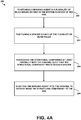
Figure 2A is a perspective view of an example spacer that can be used in the system shown inFigure 1 . -
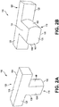
Figure 2B is a bottom perspective view of the spacer ofFigure 2A . -
Figure 3A is perspective view of an example spacer positioned in a channel of a rail in the system ofFigure 1 . -
Figure 3B is a section A-A cross-section view of the spacer and rail ofFigure 3A with a structural component positioned in the channel of the rail. -
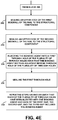
Figure 4A is a flowchart of an example method for bonding a structural component to a rail using the system ofFigures 1 to 3B . -
Figure 4B is a flowchart of a method, which is a continuation of the method for bonding a structural component to a rail using the systems ofFigures 1 to 3B shown inFigure 4A . -
Figure 4C is a flowchart of a method, which is a continuation of the method for bonding a structural component to a rail using the systems ofFigures 1 to 3B shown inFigure 4A . -
Figure 4D is a flowchart of a method, which is a continuation of the method for bonding a structural component to a rail using the systems ofFigures 1 to 3B shown inFigure 4A . -
Figure 4E is a flowchart of a method, which is a continuation of the method for bonding a structural component to a rail using the systems ofFigures 1 to 3B shown inFigure 4A . -
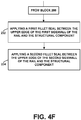
Figure 4F is a flowchart of a method, which is a continuation of the method for bonding a structural component to a rail using the systems ofFigures 1 to 3B shown inFigure 4A . -
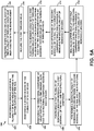
Figure 5A is a flowchart of another example method for bonding a structural component to a rail using the systems ofFigures 1 to 3B . -
Figure 5B is a flowchart of a method, which is a continuation of the method for bonding a structural component to a rail using the systems ofFigures 1 to 3B shown inFigure 5A . - The examples described herein provide an improved spacer and corresponding method of use when bonding a structural component (e.g., aircraft canopy) to a corresponding structural channel (e.g., canopy rail). Within examples, a system for bonding a structural component to a rail is described herein. More specifically, as described herein, joining a structural component to a rail using a bonding compound can assure an airtight seal and uniform distribution of loads and stresses along that fitting.
- Accordingly, the improved system described herein can enable joining of a structural component to a corresponding rail using a bonding component while assuring that the structural component seats into the rail with uniform pre-determined fit and structural integrity. In particular, the system described herein includes a plurality of spacers each including a stem and a top portion extending substantially perpendicular to the stem. The stem of a given spacer of the plurality of spacers is configured to be positioned in each of a plurality of blind holes in a bottom surface of the rail such that a longitudinal axis of the top portion of each spacer is parallel to a longitudinal axis of a channel of the rail. The structural component is configured to be positioned at least partially into the channel such that the structural component rests on the top portion of the plurality of spacers. When the structural component is positioned on the top portion of the plurality of spacers, a first gap is defined between the structural component and the bottom surface of the rail, a second gap is defined between the structural component and a first sidewall of the rail, and a third gap is defined between the structural component and a second sidewall of the rail.
- Various other features of the example systems discussed above, as well as methods for using these systems, are also described hereinafter with reference to the accompanying figures. Illustrative, non-exhaustive examples, which may or may not be claimed, of the subject matter according the present disclosure are provided below.
- With reference to the Figures,
Figure 1 illustrates anexample system 100 for bonding astructural component 102 to arail 104. As shown inFigure 1 , thesystem 100 includes arail 104 including abottom surface 106, afirst sidewall 108 extending from thebottom surface 106, and asecond sidewall 110 extending from thebottom surface 106 to thereby define achannel 112. Therail 104 further includes a plurality ofblind holes 114 defined in thebottom surface 106. Thesystem 100 also includes a plurality ofspacers 116 each including astem 118 and atop portion 120 extending substantially perpendicular to thestem 118. Thestem 118 of a given spacer of the plurality ofspacers 116 is configured to be positioned in each of the plurality ofblind holes 114 such that a longitudinal axis of thetop portion 120 of eachspacer 116 is parallel to a longitudinal axis of thechannel 112. In one example, each of the plurality ofspacers 116 are a different color than therail 104 such that the plurality ofspacers 116 are easily distinguishable from therail 104. Thesystem 100 also includes astructural component 102 configured to be positioned at least partially into thechannel 112 until thestructural component 102 rests on thetop portion 120 of the plurality ofspacers 116. - The plurality of
spacers 116 may be made of a material and a thickness that will bear the weight transferred from thestructural component 102 to therail 104. In one example, each of the plurality ofspacers 116 comprises a first material, and thestructural component 102 comprises a second material that is different than the first material. In one example, the first material is softer than the second material. As used herein, the "softness" of the first material and the second material may be defined by a hardness scale value (e.g., Rockwell or Shore hardness), a Vickers hardness value, a compression, a durability, or a plastic deformation. Such an arrangement may help prevent damage to thestructural component 102 when it is positioned on the plurality ofspacers 116. However, the first material should be sufficiently strong to avoid noticeable deformation under the weight of thestructural component 102. The first material of the plurality ofspacers 116 may include any material that is compatible with therail 104, thestructural component 102, and thebonding agent 103 used to secure thestructural component 102 to therail 104. - The vertical height of the top of each of the plurality of
spacers 116 determines the space between thebottom surface 106 of therail 104 and the bottom of thestructural component 102. Such a vertical height may be selected based on the particularstructural component 102 andparticular rail 104 into which thestructural component 102 is positioned. - The
top portion 120 of each of the plurality ofspacers 116 includes atop surface 124, abottom surface 126 opposite thetop surface 124, afirst side surface 128, and asecond side surface 130 opposite thefirst side surface 128. In one example, as shown inFigures 2A-2B , each of thetop surface 124, thebottom surface 126, thefirst side surface 128, and thesecond side surface 130 are substantially flat. The substantiallyflat top surface 124 helps to ensure a solid fit with thestructural component 102, while the substantiallyflat bottom surface 126 helps to ensure a snug fit with thebottom surface 106 of therail 104. Thefirst side surface 128 andsecond side surface 130 may be substantially flat to ensure that thebonding agent 103 can flow around thetop surface 124 of thespacer 116, as discussed in additional detail below with respect toFigures 4 and5 . - In one example, the
bottom surface 106 of therail 104 further includes a plurality of throughholes 132 interspaced between the plurality ofblind holes 114 on thebottom surface 106 of therail 104, as shown inFigure 3A . As used herein, "interspaced" means occupying a space between two things. For example, the plurality of throughholes 132 are interspaced between the plurality ofblind holes 114 on thebottom surface 106 of therail 104 such that thebottom surface 106 alternates between athough hole 132 and ablind hole 114. The plurality ofblind holes 114 and plurality of thoughholes 132 may be evenly interspaced, or may be unevenly interspaced such that there is a different distance between adjacent holes. The plurality of throughholes 132 provide a location into which thebonding agent 103 can be injected, as discussed in addition detail below with respect toFigures 4 and5 . - The
stem 118 of each of the plurality ofspacers 116 may include afirst side 134, asecond side 136 opposite thefirst side 134, athird side 138, afourth side 140 opposite thethird side 138, and abottom side 139. Thebottom side 139 may be substantially flat such that it sits flat on the bottom surface of theblind hole 114. In one example, thefirst side 134 and thesecond side 136 are substantially flat and are parallel to the longitudinal axis of thechannel 112, and thethird side 138 and thefourth side 140 have a radius ofcurvature 142 corresponding to adiameter 115 of each of the plurality ofblind holes 114. In such an example, the roundedthird side 138 andfourth side 140 of thestem 118 of each of the plurality ofspacers 116 has a light to no interference fit into each of the plurality ofblind holes 114. In one example, thestem 118 of each of the plurality ofspacers 116 is press fit into each of the plurality ofblind holes 114. In another example, abonding agent 103 is positioned into each of the plurality ofblind holes 114 before inserting thestem 118 of each of the plurality ofspacers 116. In such an example, the substantially flatfirst side 134 andsecond side 136 can enableexcess bonding agent 103 to exit the plurality of blind holes when thestem 118 is inserted therein. Further, the substantially flatfirst side 134 andsecond side 136 can enable thebonding agent 103 to flow into the plurality ofblind holes 114, further assuring the quality of the bond between thestructural component 102 and therail 104. - The distance between the
first side surface 128 and thesecond side surface 130 of thetop portion 120 of each of the plurality ofspacers 116 may be equal to the distance between thefirst side 134 and thesecond side 136 of thestem 118 of each of the plurality ofspacers 116. Such an arrangement may help ensure that thebonding agent 103 can flow both around thetop portion 120 of each of the plurality ofspacers 116 as well as into each of the plurality ofblind holes 114 in thebottom surface 106 of therail 104. - The plurality of
blind holes 114 are drilled with pre-determined spacing such that when the plurality ofspacers 116 are positioned in the corresponding plurality ofblind holes 114, the plurality ofspacers 116 satisfy fit and load bearing requirements to support thestructural component 102 positioned thereon. When thestructural component 102 is positioned on thetop portion 120 of the plurality ofspacers 116, afirst gap 144 is defined between thestructural component 102 and thebottom surface 106 of therail 104, asecond gap 146 is defined between thestructural component 102 and afirst sidewall 108 of therail 104, and athird gap 148 is defined between thestructural component 102 and asecond sidewall 110 of therail 104. The various gap sizes may be determined based on the width of the distance between thefirst sidewall 108 and thesecond sidewall 110, the width of thestructural component 102, and the viscosity of thebonding agent 103 used to bond thestructural component 102 to therail 104. - In one example, the
system 100 further includes a first plurality ofremovable spacers 150 configured to be removably positioned between thefirst sidewall 108 of therail 104 and thestructural component 102. Thesystem 100 may further include a second plurality ofremovable spacers 152 configured to be removably positioned between thesecond sidewall 110 of therail 104 and thestructural component 102. The first plurality ofremovable spacers 150 and the second plurality ofremovable spacers 152 may help center thestructural component 102 between thefirst sidewall 108 and thesecond sidewall 110 of therail 104 before thebonding agent 103 is injected into thechannel 112. As thebonding agent 103 is injected into thechannel 112, the first plurality ofremovable spacers 150 and the second plurality ofremovable spacers 152 may be removed. - In one particular example, the
structural component 102 comprises an aircraft canopy, and therail 104 comprises a canopy rail. However, the use of thesystem 100 described above is not limited to aircraft canopies. Instead, thesystem 100 described above can be used in any circumstance where it is necessary to bond a structural component to and within a channel defined by a rail having a bottom surface and two opposing sidewalls. -
Figure 4A is a block diagram of an example method for bonding astructural component 102 to arail 104. As discussed above, therail 104 includes abottom surface 106, afirst sidewall 108 extending from thebottom surface 106, and asecond sidewall 110 extending from thebottom surface 106 to thereby define achannel 112.Method 200 shown inFigure 4A presents an example of a method that could be used to assemble thesystem 100 discussed above in relation toFigures 1-3B , as an example.Method 200 includes one or more operations, functions, or actions as illustrated by one or more of blocks 202-208. In one example, an aircraft component supplier can manufacture or deliver thestructural component 102 and/or therail 104 to an end user such as an aircraft manufacturer. The aircraft manufacturer could then perform the actions recited in blocks 202-208 below. Although the blocks are illustrated in a sequential order, these blocks may also be performed in parallel, and/or in a different order than those described herein. Also, the various blocks may be combined into fewer blocks, divided into additional blocks, and/or removed based upon the desired implementation. - Initially, at
block 202, themethod 200 includes positioning abonding agent 103 in a plurality ofblind holes 114 defined in thebottom surface 106 of therail 104. Thebonding agent 103 may be selected based on the particularstructural component 102 that will be bonded to aparticular rail 104. Atblock 204, themethod 200 includes positioning aspacer 116 in each of the plurality ofblind holes 114. As discussed above, eachspacer 116 has astem 118 and atop portion 120 extending substantially perpendicular to thestem 118 to form a t-shape. Thestem 118 of thespacer 116 is positioned in each of the plurality ofblind holes 114 such that a longitudinal axis of thetop portion 120 of eachspacer 116 is parallel to a longitudinal axis of thechannel 112. In one example, positioning aspacer 116 in each of the plurality ofblind holes 114 comprises positioning eachspacer 116 such that the longitudinal axis of thetop portion 120 of eachspacer 116 is positioned in a flow direction of thebonding agent 103 when thebonding agent 103 is injected into thechannel 112. As such, eachspacer 116 is aligned with the injection flow path of thebonding agent 103 to thereby reduce the impact thespacer 116 has on the flow of thebonding agent 103. - At
block 206, themethod 200 includes positioning thestructural component 102 at least partially into thechannel 112 such that thestructural component 102 rests on eachspacer 116. As discussed above, afirst gap 144 is defined between thestructural component 102 and thebottom surface 106 of therail 104, asecond gap 146 is defined between thestructural component 102 and thefirst sidewall 108 of therail 104, and athird gap 148 is defined between thestructural component 102 and thesecond sidewall 110 of therail 104. - At
block 208, themethod 200 includes injecting thebonding agent 103 into thechannel 112 such that each of thefirst gap 144, thesecond gap 146, and thethird gap 148 includes thebonding agent 103 to thereby bond thestructural component 102 to therail 104. In particular, thebonding agent 103 cures for a time period to ensure that thestructural component 102 is permanently bonded to therail 104. - In one example, as shown in
Figure 4B , atblock 210 themethod 200 further includes sealing an upper edge of thefirst sidewall 108 of therail 104 to thestructural component 102. Atblock 212, themethod 200 further includes sealing an upper edge of thesecond sidewall 110 of therail 104 to thestructural component 102. In one particular example, sealing the upper edge of thefirst sidewall 108 of therail 104 and thestructural component 102 comprises applying a first fillet seal, and sealing the upper edge of thesecond sidewall 110 of therail 104 and thestructural component 102 comprises applying a second fillet seal. As used herein, applying a seal may involve the steps of applying a sealant to a surface and shaping at least a portion of the sealant (while the sealant is wet or uncured) into a fillet or curved surface. Other sealing methods are possible as well. - In one example, the
bonding agent 103 is injected into thechannel 112 prior to positioning thestructural component 102 at least partially into thechannel 112 such that thestructural component 102 rests on eachspacer 116. In such an example, as shown inFigure 4C , atblock 214 themethod 200 may further include removingexcess bonding agent 103 above an upper edge of thefirst sidewall 108 of therail 104 and above an upper edge of thesecond sidewall 110 of therail 104. - In another example, the step of injecting the
bonding agent 103 into thechannel 112 includes injecting thebonding agent 103 into thesecond gap 146 between thestructural component 102 and thefirst sidewall 108 of therail 104, and injecting thebonding agent 103 into thethird gap 148 between thestructural component 102 and thesecond sidewall 110 of therail 104. - In another example, as shown in
Figure 4D , atblock 216 themethod 200 further includes positioning a first plurality ofremovable spacers 150 between thefirst sidewall 108 of therail 104 and thestructural component 102. Atblock 218, themethod 200 further includes positioning a second plurality ofremovable spacers 152 between thesecond sidewall 110 of therail 104 and thestructural component 102. Atblock 220, themethod 200 further includes removing the first plurality ofremovable spacers 150 and the second plurality ofremovable spacers 152 prior to injecting thebonding agent 103 into thechannel 112. As discussed above, the first plurality ofremovable spacers 150 and the second plurality ofremovable spacers 152 may help center thestructural component 102 between thefirst sidewall 108 and thesecond sidewall 110 of therail 104 before thebonding agent 103 is injected into thechannel 112. - In one example, the
bottom surface 106 of therail 104 includes a plurality of throughholes 132. In such an example, as shown inFigure 4E , atblock 222 themethod 200 further includes sealing an upper edge of thefirst sidewall 108 of therail 104 to thestructural component 102. Atblock 224, themethod 200 further includes sealing an upper edge of thesecond sidewall 110 of therail 104 to thestructural component 102. Atblock 226, themethod 200 further includes injecting thebonding agent 103 into a first through hole of the plurality of throughholes 132 such that thebonding agent 103 exits an adjacent second through hole of the plurality of throughholes 132. Atblock 228, themethod 200 further includes sealing the first through hole. Atblock 230, themethod 200 further includes repeating the steps fromblocks holes 132 have been injected with thebonding agent 103 and each of thefirst gap 144, thesecond gap 146, and thethird gap 148 includes thebonding agent 103. The plurality of throughholes 132 may be interspaced evenly between the plurality ofblind holes 114 on thebottom surface 106 of therail 104. - In one particular example, sealing the upper edge of the
first sidewall 108 of therail 104 to thestructural component 102 comprises applying a first dam seal between the upper edge of thefirst sidewall 108 of therail 104 and thestructural component 102, and sealing an upper edge of thesecond sidewall 110 of therail 104 to thestructural component 102 comprises applying a second dam seal between the upper edge of thesecond sidewall 110 of therail 104 and thestructural component 102. In another example, as shown inFigure 4F , atblock 232 themethod 200 further includes applying a first fillet seal between the upper edge of thefirst sidewall 108 of therail 104 and thestructural component 102. Atblock 234, themethod 200 further includes applying a second fillet seal between the upper edge of thesecond sidewall 110 of therail 104 and thestructural component 102. -
Figure 5A is a block diagram of another example method for bonding astructural component 102 to arail 104. As discussed above, therail 104 includes abottom surface 106, afirst sidewall 108 extending from thebottom surface 106, and asecond sidewall 110 extending from thebottom surface 106 to thereby define achannel 112.Method 300 shown inFigure 5A presents an example of a method that could be used to assemble thesystem 100 discussed above in relation toFigures 1-3B , as an example.Method 300 includes one or more operations, functions, or actions as illustrated by one or more of blocks 302-320. In one example, an aircraft component supplier can manufacture or deliver thestructural component 102 and/or therail 104 to an end user such as an aircraft manufacturer. The aircraft manufacturer could then perform the actions recited in blocks 302-320 below. Although the blocks are illustrated in a sequential order, these blocks may also be performed in parallel, and/or in a different order than those described herein. Also, the various blocks may be combined into fewer blocks, divided into additional blocks, and/or removed based upon the desired implementation. - Initially, at
block 302, themethod 300 includes positioning abonding agent 103 in a plurality ofblind holes 114 defined in thebottom surface 106 of therail 104. Atblock 304, themethod 300 includes positioning aspacer 116 in each of the plurality ofblind holes 114, where each spacer has astem 118 and atop portion 120 extending substantially perpendicular to thestem 118, and where thestem 118 of thespacer 116 is positioned in each of the plurality ofblind holes 114 such that a longitudinal axis of thetop portion 120 of eachspacer 116 is parallel to a longitudinal axis of thechannel 112. Atblock 306, themethod 300 includes positioning thestructural component 102 at least partially into thechannel 112 such that thestructural component 102 rests on eachspacer 116, where afirst gap 144 is defined between thestructural component 102 and thebottom surface 106 of therail 104, asecond gap 146 is defined between thestructural component 102 and thefirst sidewall 108 of therail 104, and athird gap 148 is defined between thestructural component 102 and thesecond sidewall 110 of therail 104. - At
block 308, themethod 300 further includes positioning a first plurality ofremovable spacers 150 between thefirst sidewall 108 of therail 104 and thestructural component 102. Atblock 310, themethod 300 further includes positioning a second plurality ofremovable spacers 152 between thesecond sidewall 110 of therail 104 and thestructural component 102. Atblock 312, themethod 300 further includes sealing an upper edge of thefirst sidewall 108 of therail 104 to thestructural component 102 while simultaneously removing the first plurality ofremovable spacers 150. Atblock 314, themethod 300 further includes sealing an upper edge of thesecond sidewall 110 of therail 104 to thestructural component 102 while simultaneously removing the second plurality ofremovable spacers 152. As discussed above, the previous two steps (312-314) may comprise a dam seal or other type of seal to create a closed cavity in thechannel 112. - At
block 316, themethod 300 further includes injecting thebonding agent 103 into a first through hole of a plurality of throughholes 132 in thebottom surface 106 of therail 104 such that thebonding agent 103 exits an adjacent through hole of the plurality of throughholes 132. Atblock 318, themethod 300 includes sealing the first through hole. Atblock 320, themethod 300 includes repeating the previous two steps (316-318) such that each of the plurality of throughholes 132 have been injected with thebonding agent 103 and each of thefirst gap 144, thesecond gap 146, and thethird gap 148 includes thebonding agent 103 to thereby bond thestructural component 102 to therail 104. - In one example, as shown in
Figure 5B , atblock 322 themethod 300 further includes applying a first fillet seal between the upper edge of thefirst sidewall 108 of therail 104 and thestructural component 102. Atblock 324, themethod 300 may further include applying a second fillet seal between the upper edge of thesecond sidewall 110 of therail 104 and thestructural component 102. - The disclosure further comprises the following illustrative, non-exhaustive enumerated examples, which may or may not be claimed:
- 1. A method (200) for bonding a structural component (102) to a rail (104), the rail (104) including a bottom surface (106), a first sidewall (108) extending from the bottom surface (106), and a second sidewall (110) extending from the bottom surface (106) to thereby define a channel (112), the method (200) comprising:
- positioning (202) a bonding agent (103) in a plurality of blind holes (114) defined in the bottom surface (106) of the rail (104);
- positioning (204) a spacer (116) in each of the plurality of blind holes (114), wherein each spacer (116) has a stem (118) and a top portion (120) extending substantially perpendicular to the stem (118), and wherein the stem (118) of the spacer (116) is positioned in each of the plurality of blind holes (114) such that a longitudinal axis of the top portion (120) of each spacer (116) is parallel to a longitudinal axis of the channel (112);
- positioning (206) the structural component (102) at least partially into the channel (112) such that the structural component (102) rests on each spacer (116), wherein a first gap (144) is defined between the structural component (102) and the bottom surface (106) of the rail (104), wherein a second gap (146) is defined between the structural component (102) and the first sidewall (108) of the rail (104), and wherein a third gap (148) is defined between the structural component (102) and the second sidewall (110) of the rail (104); and
- injecting (208) the bonding agent into the channel (112) such that each of the first gap (144), the second gap (146), and the third gap (148) includes the bonding agent (103) to thereby bond the structural component (102) to the rail (104).
- 2. The method (200) of example 1, further comprising:
- sealing (210) an upper edge of the first sidewall (108) of the rail (104) to the structural component (102); and
- sealing (212) an upper edge of the second sidewall (110) of the rail (104) to the structural component (102).
- 3. The method (200) of example 2, wherein sealing (210) the upper edge of the first sidewall (108) of the rail (104) and the structural component (102) comprises applying a first fillet seal, and wherein sealing (212) the upper edge of the second sidewall (110) of the rail (104) and the structural component (102) comprises applying a second fillet seal.
- 4. The method (200) of any one of examples 1 to 3, wherein the bonding agent (103) is injected into the channel (112) prior to positioning the structural component (102) at least partially into the channel (112) such that the structural component (102) rests on each spacer (116), the method (200) further comprising:
removing (214) excess bonding agent above an upper edge of the first sidewall (108) of the rail (104) and above an upper edge of the second sidewall (110) of the rail (104). - 5. The method (200) of any one of examples 1 to 4, wherein injecting the bonding agent (103) into the channel (112) comprises:
- injecting the bonding agent into the second gap (146) between the structural component (102) and the first sidewall (108) of the rail (104); and
- injecting the bonding agent into the third gap (148) between the structural component (102) and the second sidewall (110) of the rail (104).
- 6. The method (200) of any one of examples 1 to 5, further comprising:
- positioning (216) a first plurality of removable spacers (150) between the first sidewall (108) of the rail (104) and the structural component (102); and
- positioning (218) a second plurality of removable spacers (152) between the second sidewall (110) of the rail (104) and the structural component (102).
- 7. The method (200) of example 6, further comprising:
removing (220) the first plurality of removable spacers (150) and the second plurality of removable spacers (152) prior to injecting the bonding agent into the channel (112). - 8. The method (200) of any one of examples 1 to 7, wherein the bottom surface (106) of the rail (104) includes a plurality of through holes (132), the method (200) further comprising:
- (i) sealing (222) an upper edge of the first sidewall (108) of the rail (104) to the structural component (102);
- (ii) sealing (224) an upper edge of the second sidewall (110) of the rail (104) to the structural component (102);
- (iii) injecting (226) the bonding agent into a first through hole of the plurality of through holes (132) such that the bonding agent exits an adjacent second through hole of the plurality of through holes (132);
- (iv) sealing (228) the first through hole; and
- (v) repeating steps (iii) and (iv) such that each of the plurality of through holes (132) have been injected with the bonding agent and each of the first gap (144), the second gap (146), and the third gap (148) includes the bonding agent.
- 9. The method (200) of example 8, further comprising:
- applying (230) a first fillet seal between the upper edge of the first sidewall (108) of the rail (104) and the structural component (102); and
- applying (232) a second fillet seal between the upper edge of the second sidewall (110) of the rail (104) and the structural component (102).
- 10. The method (200) of example 8 or 9, wherein the plurality of through holes (132) are interspaced evenly between the plurality of blind holes (114) on the bottom surface (106) of the rail (104).
- 11. The method (200) of any one of examples 1 to 10, wherein positioning a spacer (116) in each of the plurality of blind holes (114) comprises positioning each spacer (116) such that the longitudinal axis of the top portion (120) of each spacer (116) is positioned in a flow direction of the bonding agent when the bonding agent is injected into the channel (112).
- 12. A system (100) for bonding a structural component (102) to a rail (104), the system (100) comprising:
- a rail (104) including a bottom surface (106), a first sidewall (108) extending from the bottom surface (106), and a second sidewall (110) extending from the bottom surface (106) to thereby define a channel (112), wherein the rail (104) further includes a plurality of blind holes (114) defined in the bottom surface (106);
- a plurality of spacers (116) each including a stem (118) and a top portion (120) extending substantially perpendicular to the stem (118), and wherein the stem (118) of a given spacer of the plurality of spacers (116) is configured to be positioned in each of the plurality of blind holes (114) such that a longitudinal axis of the top portion (120) of each spacer (116) is parallel to a longitudinal axis of the channel (112); and
- a structural component (102) configured to be positioned at least partially into the channel (112) such that the structural component (102) rests on the top portion (120) of the plurality of spacers (116).
- 13. The system (100) of example 12, wherein each of the plurality of spacers (116) comprises a first material, wherein the structural component (102) comprises a second material that is different than the first material, and wherein the first material is softer than the second material.
- 14. The system (100) of example 12 or 13, wherein the top portion (120) of each of the plurality of spacers (120) includes a top surface (124), a bottom surface (126) opposite the top surface (124), a first side surface (128), and a second side surface (130) opposite the first side surface (128), and wherein each of the top surface (124), the bottom surface (126), the first side surface (128), and the second side surface (130) are substantially flat.
- 15. The system (100) of any one of examples 12 to 14, wherein the bottom surface (106) of the rail (104) further includes a plurality of through holes (132) interspaced between the plurality of blind holes (114) on the bottom surface (106).
- 16. The system (100) of any one of examples 12 to 15, wherein the stem (118) of each of the plurality of spacers includes a first side (134), a second side (136) opposite the first side (134), a third side (138), and a fourth side (140) opposite the third side (138), wherein the first side (134) and the second side (136) are substantially flat and are parallel to the longitudinal axis of the channel (112), and wherein the third side (138) and the fourth side (140) have a radius of curvature (142) corresponding to a diameter (115) of each of the plurality of blind holes (114).
- 17. The system (100) of any one of examples 12 to 16, further comprising:
- a first plurality of removable spacers (150) configured to be removably positioned between the first sidewall (108) of the rail (104) and the structural component (102); and
- a second plurality of removable spacers (152) configured to be removably positioned between the second sidewall (110) of the rail (104) and the structural component (102).
- 18. The system (100) of any one of examples 12 to 17, wherein the structural component (102) comprises an aircraft canopy, and wherein the rail (104) comprises a canopy rail.
- 19. A method (300) for bonding a structural component (102) to a rail (104), the rail including a bottom surface (106), a first sidewall (108) extending from the bottom surface (106), and a second sidewall (110) extending from the bottom surface (106) to thereby define a channel (112), the method (300) comprising:
- (i) positioning (302) a bonding agent in a plurality of blind holes (114) defined in the bottom surface (106) of the rail (104);
- (ii) positioning (304) a spacer (116) in each of the plurality of blind holes (114), wherein each spacer (116) has a stem (118) and a top portion (120) extending substantially perpendicular to the stem (118), and wherein the stem (118) of the spacer (116) is positioned in each of the plurality of blind holes (114) such that a longitudinal axis of the top portion (120) of each spacer (116) is parallel to a longitudinal axis of the channel (112);
- (iii) positioning (306) the structural component (102) at least partially into the channel (112) such that the structural component (102) rests on each spacer (116), wherein a first gap (144) is defined between the structural component (102) and the bottom surface (106) of the rail (104), wherein a second gap (146) is defined between the structural component (102) and the first sidewall (108) of the rail (104), and wherein a third gap (148) is defined between the structural component (102) and the second sidewall (110) of the rail (104);
- (iv) positioning (308) a first plurality of removable spacers (150) between the first sidewall (108) of the rail (104) and the structural component (102);
- (v) positioning (310) a second plurality of removable spacers (152) between the second sidewall (110) of the rail (104) and the structural component (102);
- (vi) sealing (312) an upper edge of the first sidewall (108) of the rail (104) to the structural component (102) while simultaneously removing the first plurality of removable spacers (150);
- (vii) sealing (314) an upper edge of the second sidewall (110) of the rail (104) to the structural component (102) while simultaneously removing the second plurality of removable spacers (152);
- (viii) injecting (316) the bonding agent into a first through hole of a plurality of through holes (132) in the bottom surface (106) of the rail (104) such that the bonding agent exits an adjacent through hole of the plurality of through holes (132);
- (ix) sealing (318) the first through hole; and
- (x) repeating (320) steps (viii) and (ix) such that each of the plurality of through holes (132) have been injected with the bonding agent and each of the first gap (144), the second gap (146), and the third gap (148) includes the bonding agent to thereby bond the structural component (102) to the rail (104).
- 20. The method (300) of example 19, further comprising:
- applying (322) a first fillet seal between the upper edge of the first sidewall (108) of the rail (104) and the structural component (102); and
- applying (324) a second fillet seal between the upper edge of the second sidewall (110) of the rail (104) and the structural component (102).
- 1A. A method (200) for bonding a structural component (102) to a rail (104), the rail (104) including a bottom surface (106), a first sidewall (108) extending from the bottom surface (106), and a second sidewall (110) extending from the bottom surface (106) to thereby define a channel (112), the method (200) comprising:
- positioning (202) a bonding agent (103) in a plurality of blind holes (114) defined in the bottom surface (106) of the rail (104);
- positioning (204) a plurality of spacers (116) in the plurality of blind holes (114) such that each of the plurality of blind holes (114) receives one of the plurality of spacers (116), wherein each of the plurality of spacers (116) has a stem (118) and a top portion (120) extending substantially perpendicular to the stem (118), and wherein the stem (118) of each of the plurality of spacers (116) is positioned in each of the plurality of blind holes (114) such that a longitudinal axis of the top portion (120) of each of the plurality of spacers (116) is parallel to a longitudinal axis of the channel (112);
- positioning (206) the structural component (102) at least partially into the channel (112) such that the structural component (102) rests on each of the plurality of spacers (116), wherein a first gap (144) is defined between the structural component (102) and the bottom surface (106) of the rail (104), wherein a second gap (146) is defined between the structural component (102) and the first sidewall (108) of the rail (104), and wherein a third gap (148) is defined between the structural component (102) and the second sidewall (110) of the rail (104); and
- injecting (208) the bonding agent into the channel (112) such that each of the first gap (144), the second gap (146), and the third gap (148) includes the bonding agent (103) to thereby bond the structural component (102) to the rail (104).
- 2A. The method (200) of example 1A, further comprising:
- sealing (210) an upper edge of the first sidewall (108) of the rail (104) to the structural component (102); and
- sealing (212) an upper edge of the second sidewall (110) of the rail (104) to the structural component (102).
- 3A. The method (200) of example 2A, wherein sealing (210) the upper edge of the first sidewall (108) of the rail (104) and the structural component (102) comprises applying a first fillet seal, and wherein sealing (212) the upper edge of the second sidewall (110) of the rail (104) and the structural component (102) comprises applying a second fillet seal.
- 4A. The method (200) of any one of examples 1A to 3A, wherein the bonding agent (103) is injected into the channel (112) prior to positioning the structural component (102) at least partially into the channel (112) such that the structural component (102) rests on each of the plurality of spacers (116), the method (200) further comprising:
removing (214) excess bonding agent above an upper edge of the first sidewall (108) of the rail (104) and above an upper edge of the second sidewall (110) of the rail (104). - 5A. The method (200) of any one of examples 1A to 4A, wherein injecting the bonding agent (103) into the channel (112) comprises:
- injecting the bonding agent into the second gap (146) between the structural component (102) and the first sidewall (108) of the rail (104); and
- injecting the bonding agent into the third gap (148) between the structural component (102) and the second sidewall (110) of the rail (104).
- 6A. The method (200) of any one of examples 1A to 5A, further comprising:
- positioning (216) a first plurality of removable spacers (150) between the first sidewall (108) of the rail (104) and the structural component (102); and
- positioning (218) a second plurality of removable spacers (152) between the second sidewall (110) of the rail (104) and the structural component (102).
- 7A. The method (200) of example 6A, further comprising:
removing (220) the first plurality of removable spacers (150) and the second plurality of removable spacers (152) prior to injecting the bonding agent into the channel (112). - 8A. The method (200) of any one of examples 1A to 7A, wherein the bottom surface (106) of the rail (104) includes a plurality of through holes (132), the method (200) further comprising:
- (i) sealing (222) an upper edge of the first sidewall (108) of the rail (104) to the structural component (102);
- (ii) sealing (224) an upper edge of the second sidewall (110) of the rail (104) to the structural component (102);
- (iii) injecting (226) the bonding agent into a first through hole of the plurality of through holes (132) such that the bonding agent exits an adjacent second through hole of the plurality of through holes (132);
- (iv) sealing (228) the first through hole; and
- (v) repeating steps (iii) and (iv) such that each of the plurality of through holes (132) have been injected with the bonding agent and each of the first gap (144), the second gap (146), and the third gap (148) includes the bonding agent.
- 9A. The method (200) of example 8A, further comprising:
- applying (230) a first fillet seal between the upper edge of the first sidewall (108) of the rail (104) and the structural component (102); and
- applying (232) a second fillet seal between the upper edge of the second sidewall (110) of the rail (104) and the structural component (102).
- 10A. The method (200) of example 8A or 9A, wherein the plurality of through holes (132) are interspaced evenly between the plurality of blind holes (114) on the bottom surface (106) of the rail (104).
- 11A. The method (200) of any one of examples 1A to 10A, wherein positioning one of the plurality of spacers (116) in each of the plurality of blind holes (114) comprises positioning each of the plurality of spacers (116) such that the longitudinal axis of the top portion (120) of each of the plurality of spacers (116) is positioned in a flow direction of the bonding agent when the bonding agent is injected into the channel (112).
- 12A. A system (100) for bonding a structural component (102) to a rail (104), the system (100) comprising:
- the rail (104) including a bottom surface (106), a first sidewall (108) extending from the bottom surface (106), and a second sidewall (110) extending from the bottom surface (106) to thereby define a channel (112), wherein the rail (104) further includes a plurality of blind holes (114) defined in the bottom surface (106);
- a plurality of spacers (116) each including a stem (118) and a top portion (120) extending substantially perpendicular to the stem (118), and wherein the stem (118) of any spacer of the plurality of spacers (116) is configured to be positioned in each of the plurality of blind holes (114) such that a longitudinal axis of the top portion (120) of each of the plurality of spacers (116) is parallel to a longitudinal axis of the channel (112); and
- a structural component (102) configured to be positioned at least partially into the channel (112) such that the structural component (102) rests on the top portion (120) of the plurality of spacers (116).
- 13A. The system (100) of example 12A, wherein each of the plurality of spacers (116) comprises a first material, wherein the structural component (102) comprises a second material that is different than the first material, and wherein the first material is softer than the second material.
- 14A. The system (100) of example 12A or 13A, wherein the top portion (120) of each of the plurality of spacers (120) includes a spacer top surface (124), a spacer bottom surface (126) opposite the spacer top surface (124), a first side surface (128), and a second side surface (130) opposite the first side surface (128), and wherein each of the spacer top surface (124), the spacer bottom surface (126), the first side surface (128), and the second side surface (130) are substantially flat.
- 15A. The system (100) of any one of examples 12A to 14A, wherein the bottom surface (106) of the rail (104) further includes a plurality of through holes (132) interspaced between the plurality of blind holes (114) on the bottom surface (106).
- 16A. The system (100) of any one of examples 12Ato 15A, wherein the stem (118) of each of the plurality of spacers includes a first side (134), a second side (136) opposite the first side (134), a third side (138), and a fourth side (140) opposite the third side (138), wherein the first side (134) and the second side (136) are substantially flat and are parallel to the longitudinal axis of the channel (112), and wherein the third side (138) and the fourth side (140) have a radius of curvature (142) corresponding to a diameter (115) of each of the plurality of blind holes (114).
- 17A. The system (100) of any one of examples 12A to 16A, further comprising:
- a first plurality of removable spacers (150) configured to be removably positioned between the first sidewall (108) of the rail (104) and the structural component (102); and
- a second plurality of removable spacers (152) configured to be removably positioned between the second sidewall (110) of the rail (104) and the structural component (102).
- 18A. The system (100) of any one of examples 12A to 17A, wherein the structural component (102) comprises an aircraft canopy, and wherein the rail (104) is a canopy rail.
- 19A. A method (300) for bonding a structural component (102) to a rail (104), the rail (104) including a bottom surface (106), a first sidewall (108) extending from the bottom surface (106), and a second sidewall (110) extending from the bottom surface (106) to thereby define a channel (112), the method (300) comprising:
- (i) positioning (302) a bonding agent in a plurality of blind holes (114) defined in the bottom surface (106) of the rail (104);
- (ii) positioning (304) a plurality of spacers (116) in the plurality of blind holes (114) such that each of the plurality of blind holes (114) received one of the plurality of spacers (116), wherein each of the plurality of spacers (116) has a stem (118) and a top portion (120) extending substantially perpendicular to the stem (118), and wherein the stem (118) of each of the plurality of spacers (116) is positioned in each of the plurality of blind holes (114) such that a longitudinal axis of the top portion (120) of each of the plurality of spacers (116) is parallel to a longitudinal axis of the channel (112);
- (iii) positioning (306) the structural component (102) at least partially into the channel (112) such that the structural component (102) rests on each of the plurality of spacers (116), wherein a first gap (144) is defined between the structural component (102) and the bottom surface (106) of the rail (104), wherein a second gap (146) is defined between the structural component (102) and the first sidewall (108) of the rail (104), and wherein a third gap (148) is defined between the structural component (102) and the second sidewall (110) of the rail (104);
- (iv) positioning (308) a first plurality of removable spacers (150) between the first sidewall (108) of the rail (104) and the structural component (102);
- (v) positioning (310) a second plurality of removable spacers (152) between the second sidewall (110) of the rail (104) and the structural component (102);
- (vi) sealing (312) an upper edge of the first sidewall (108) of the rail (104) to the structural component (102) while simultaneously removing the first plurality of removable spacers (150);
- (vii) sealing (314) an upper edge of the second sidewall (110) of the rail (104) to the structural component (102) while simultaneously removing the second plurality of removable spacers (152);
- (viii) injecting (316) the bonding agent into a first through hole of a plurality of through holes (132) in the bottom surface (106) of the rail (104) such that the bonding agent exits an adjacent through hole of the plurality of through holes (132);
- (ix) sealing (318) the first through hole; and
- (x) repeating (320) steps (viii) and (ix) such that each of the plurality of through holes (132) have been injected with the bonding agent and each of the first gap (144), the second gap (146), and the third gap (148) includes the bonding agent to thereby bond the structural component (102) to the rail (104).
- 20A. The method (300) of example 19A, further comprising:
- applying (322) a first fillet seal between the upper edge of the first sidewall (108) of the rail (104) and the structural component (102); and
- applying (324) a second fillet seal between the upper edge of the second sidewall (110) of the rail (104) and the structural component (102).
- In the above description, numerous specific details are set forth to provide a thorough understanding of the disclosed concepts, which may be practiced without some or all of these particulars. In other instances, details of known devices and/or processes have been omitted to avoid unnecessarily obscuring the disclosure. While some concepts were described in conjunction with specific examples, it will be understood that these examples are not intended to be limiting.
- In
Figures 4A-5B , referred to above, the blocks may represent operations and/or portions thereof and lines connecting the various blocks do not imply any particular order or dependency of the operations or portions thereof. It will be understood that not all dependencies among the various disclosed operations are necessarily represented.Figures 4A-5B and the accompanying disclosure describing the operations of the method(s) set forth herein should not be interpreted as necessarily determining a sequence in which the operations are to be performed. Rather, although one illustrative order is indicated, it is to be understood that the sequence of the operations may be modified when appropriate. Accordingly, certain operations may be performed in a different order or simultaneously. Additionally, those skilled in the art will appreciate that not all operations described need be performed. - Unless otherwise indicated, the terms "first," "second," etc. are used herein merely as labels, and are not intended to impose ordinal, positional, or hierarchical requirements on the items to which these terms refer. Moreover, reference to, e.g., a "second" item does not require or preclude the existence of, e.g., a "first" or lower-numbered item, and/or, e.g., a "third" or higher-numbered item.
- Reference herein to "one example" means that one or more feature, structure, or characteristic described in connection with the example is included in at least one implementation. The phrase "one example" in various places in the specification may or may not be referring to the same example.
- As used herein, a system, apparatus, device, structure, article, element, component, or hardware "configured to" perform a specified function is indeed capable of performing the specified function without any alteration, rather than merely having potential to perform the specified function after further modification. In other words, the system, apparatus, structure, article, element, component, or hardware "configured to" perform a specified function is specifically selected, created, implemented, utilized, programmed, and/or designed for the purpose of performing the specified function. As used herein, "configured to" denotes existing characteristics of a system, apparatus, structure, article, element, component, or hardware which enable the system, apparatus, structure, article, element, component, or hardware to perform the specified function without further modification. For purposes of this disclosure, a system, apparatus, structure, article, element, component, or hardware described as being "configured to" perform a particular function may additionally or alternatively be described as being "adapted to" and/or as being "operative to" perform that function.
- As used herein, with respect to measurements, "about" and "substantially" each means +/- 5%.
- As used herein, a "blind hole" is a hole that is recessed in a surface but does not extend through that surface.
- The description of the different advantageous arrangements has been presented for purposes of illustration and description, and is not intended to be exhaustive or limited to the examples in the form disclosed. Many modifications and variations will be apparent to those of ordinary skill in the art. Further, different advantageous examples may provide different advantages as compared to other advantageous examples. The example or examples selected are chosen and described in order to best explain the principles of the examples, the practical application, and to enable others of ordinary skill in the art to understand the disclosure for various examples with various modifications as are suited to the particular use contemplated.
Claims (15)
- A system (100) for bonding a structural component (102) to a rail (104) that comprises a bottom surface (106), a first sidewall (108) extending from the bottom surface (106), a plurality of blind holes (114) defined in the bottom surface (106), and a second sidewall (110) extending from the bottom surface (106), so that a channel (112) is defined by the bottom surface (106), the first sidewall (108), and the second sidewall (110), the system (100) comprising:a plurality of spacers (116), each comprising a stem (118) and a top portion (120), extending substantially perpendicular to the stem (118),wherein:the stem (118) of one of the plurality of spacers (116) is configured to be positioned in a corresponding one of the plurality of blind holes (114) such that a longitudinal axis of the top portion (120) of each of the plurality of spacers (116) is parallel to a longitudinal axis of the channel (112),at least a portion of the structural component (102) is configured to be positioned into the channel (112) such that the structural component (102) rests on the top portion (120) of the plurality of spacers (116),the stem (118) of each of the plurality of spacers comprises a first side (134), a second side (136) opposite the first side (134), a third side (138), and a fourth side (140), opposite the third side (138),the first side (134) and the second side (136) of the stem (118) are substantially flat and are parallel to the longitudinal axis of the channel (112), andeach of the third side (138) and the fourth side (140) of the stem (118) has a radius of curvature (142), corresponding to a diameter (115) of each of the plurality of blind holes (114).
- The system (100) of claim 1, further comprising:a first plurality of removable spacers (150), configured to be removably positioned between the first sidewall (108) of the rail (104) and the structural component (102); anda second plurality of removable spacers (152), configured to be removably positioned between the second sidewall (110) of the rail (104) and the structural component (102).
- The system (100) of claim 1 or 2, wherein the structural component (102) comprises an aircraft canopy, and wherein the rail (104) comprises a canopy rail.
- A method (300) for bonding a structural component (102) to a rail (104), the rail comprising a bottom surface (106), a first sidewall (108) extending from the bottom surface (106), and a second sidewall (110) extending from the bottom surface (106), so that a channel (112) is defined by the bottom surface (106), the first sidewall (108), and the second sidewall (110), the method (300) comprising steps of:(i) positioning a bonding agent in a plurality of blind holes (114), defined in the bottom surface (106) of the rail (104);(ii) positioning a plurality of spacers (116) into the plurality of blind holes (114), wherein each of the plurality of spacers (116) has a stem (118) and a top portion (120), extending substantially perpendicular to the stem (118), and wherein the stem (118) of each of the plurality of spacers (116) is positioned in a corresponding one of the plurality of blind holes (114) such that a longitudinal axis of the top portion (120) of each spacer (116) is parallel to a longitudinal axis of the channel (112);(iii) positioning at least a portion of the structural component (102) into the channel (112) such that the structural component (102) rests on each spacer (116), wherein a first gap (144) is defined between the structural component (102) and the bottom surface (106) of the rail (104), wherein a second gap (146) is defined between the structural component (102) and the first sidewall (108) of the rail (104), and wherein a third gap (148) is defined between the structural component (102) and the second sidewall (110) of the rail (104);(iv) positioning a first plurality of removable spacers (150) between the first sidewall (108) of the rail (104) and the structural component (102);(v) positioning a second plurality of removable spacers (152) between the second sidewall (110) of the rail (104) and the structural component (102);(vi) sealing an upper edge of the first sidewall (108) of the rail (104) to the structural component (102) while simultaneously removing the first plurality of removable spacers (150) from between the first sidewall (108) of the rail (104) and the structural component (102),(vii) sealing an upper edge of the second sidewall (110) of the rail (104) to the structural component (102) while simultaneously removing the second plurality of removable spacers (152) from between the second sidewall (110) of the rail (104) and the structural component (102),(viii) injecting the bonding agent into one through hole of a plurality of through holes (132) in the bottom surface (106) of the rail (104) such that the bonding agent exits a through hole of the plurality of through holes (132) that is adjacent the one through hole of the plurality of through holes (132)(ix) sealing the one through hole; and(x) repeating the steps (viii) and (ix) such that each of the plurality of through holes (132) has been injected with the bonding agent, and each of the first gap (144), the second gap (146), and the third gap (148) receives the bonding agent to thereby bond the structural component (102) to the rail (104).
- The method (300) of claim 4, further comprising:applying (322) a first fillet seal between the upper edge of the first sidewall (108) of the rail (104) and the structural component (102); andapplying (324) a second fillet seal between the upper edge of the second sidewall (110) of the rail (104) and the structural component (102).
- A method (200) for bonding a structural component (102) to a rail (104), the rail (104) comprising a bottom surface (106), a first sidewall (108) extending from the bottom surface (106), and a second sidewall (110) extending from the bottom surface (106) to thereby define a channel (112), the method (200) comprising steps of:positioning a bonding agent (103) in a plurality of blind holes (114), defined in the bottom surface (106) of the rail (104);positioning a plurality of spacers (116) in the plurality of blind holes (114) such that each of the plurality of blind holes (114) receives one of the plurality of spacers (116), wherein each of the plurality of spacers (116) comprises a stem (118) and a top portion (120), extending substantially perpendicular to the stem (118), and wherein the stem (118) of each of the plurality of spacers (116) is positioned in a corresponding one of the plurality of blind holes (114) such that a longitudinal axis of the top portion (120) of each of the plurality of spacers (116) is parallel to a longitudinal axis of the channel (112);positioning at least a portion of the structural component (102) into the channel (112) such that the structural component (102) rests on each of the plurality of spacers (116), wherein a first gap (144) is defined between the structural component (102) and the bottom surface (106) of the rail (104), wherein a second gap (146) is defined between the structural component (102) and the first sidewall (108) of the rail (104), and wherein a third gap (148) is defined between the structural component (102) and the second sidewall (110) of the rail (104); andinjecting the bonding agent into the channel (112) such that each of the first gap (144), the second gap (146), and the third gap (148) receives the bonding agent (103) to thereby bond the structural component (102) to the rail (104).
- The method (200) of claim 6, further comprising steps of:sealing an upper edge of the first sidewall (108) of the rail (104) to the structural component (102); andsealing an upper edge of the second sidewall (110) of the rail (104) to the structural component (102).
- The method (200) of claim 7, wherein:the step of sealing the upper edge of the first sidewall (108) of the rail (104) to the structural component (102) comprises applying a first fillet seal between the upper edge of the first sidewall (108) of the rail (104) and the structural component (102), andthe step of sealing the upper edge of the second sidewall (110) of the rail (104) to the structural component (102) comprises applying a second fillet seal between the upper edge of the second sidewall (110) of the rail (104) and the structural component (102).
- The method (200) of claim 7 or 8, wherein the bonding agent (103) is injected into the channel (112) prior to positioning at least the portion of the structural component (102) into the channel (112) such that the structural component (102) rests on each of the plurality of spacers (116), the method (200) further comprising:
a step of removing excess bonding agent above the upper edge of the first sidewall (108) of the rail (104) and above the upper edge of the second sidewall (110) of the rail (104). - The method (200) of any one of claims 7 to 9, wherein injecting the bonding agent (103) into the channel (112) comprises steps of:injecting the bonding agent into the second gap (146) between the structural component (102) and the first sidewall (108) of the rail (104); andinjecting the bonding agent into the third gap (148) between the structural component (102) and the second sidewall (110) of the rail (104),the method preferably further comprising steps of:positioning a first plurality of removable spacers (150) between the first sidewall (108) of the rail (104) and the structural component (102); andpositioning a second plurality of removable spacers (152) between the second sidewall (110) of the rail (104) and the structural component (102),the method more preferably further comprising a step of removing the first plurality of removable spacers (150) and the second plurality of removable spacers (152) from respective locations of the first plurality of removable spacers (150) and the second plurality of removable spacers (152) between the first sidewall (108) of the rail (104) and the structural component (102) and between the second sidewall (110) of the rail (104) and the structural component (102), prior to injecting the bonding agent into the channel (112).
- The method (200) of any one of the claims 7 to 10, wherein the bottom surface (106) of the rail (104) comprises a plurality of through holes (132), the method (200) further comprising steps of:(i) sealing the upper edge of the first sidewall (108) of the rail (104) to the structural component (102);(ii) sealing the upper edge of the second sidewall (110) of the rail (104) to the structural component (102);(iii) injecting the bonding agent into one through hole of the plurality of through holes (132) such that the bonding agent exits a through hole of the plurality of through holes (132) that is adjacent the one through hole of the plurality of through holes (132);(iv) sealing the one through hole; and(v) repeating the steps (iii) and (iv) such that each of the plurality of through holes (132) has been injected with the bonding agent and each of the first gap (144), the second gap (146), and the third gap (148) receives the bonding agent.
- The method (200) of claim 11, further comprising steps of:applying a first fillet seal between the upper edge of the first sidewall (108) of the rail (104) and the structural component (102); andapplying a second fillet seal between the upper edge of the second sidewall (110) of the rail (104) and the structural component (102),
and/orwherein holes of the plurality of through holes (132) are interspaced evenly between holes of the plurality of blind holes (114) on the bottom surface (106) of the rail (104). - The method (200) of any one of claims 6 to 12, wherein the step of positioning the plurality of spacers (116) in the plurality of blind holes (114) comprises positioning the plurality of spacers (116) such that the longitudinal axis of the top portion (120) of each of the plurality of spacers (116) is positioned in a flow direction of the bonding agent when the bonding agent is injected into the channel (112).
- A system (100) for bonding a structural component (102) to a rail (104) that comprises a bottom surface (106), a first sidewall (108) extending from the bottom surface (106), a plurality of blind holes (114) defined in the bottom surface (106) of the rail (104), and a second sidewall (110) extending from the bottom surface (106), so that a channel (112) is defined by the bottom surface (106), the first sidewall (108), and the second sidewall (110), the system (100) comprising:a plurality of spacers (116), each comprising a stem (118) and a top portion (120), extending substantially perpendicular to the stem (118), wherein the stem (118) of each of the plurality of spacers (116) is configured to be positioned in a corresponding one of the plurality of blind holes (114) such that a longitudinal axis of the top portion (120) of each of the plurality of spacers (116) is parallel to a longitudinal axis of the channel (112),wherein the structural component (102) is configured such that at least a portion of the structural component (102) is positionable into the channel (112) such that the structural component (102) rests on the top portion (120) of the plurality of spacers (116).
- A method (300) for bonding a structural component (102) to a rail (104), the rail (104) comprising a bottom surface (106), a first sidewall (108) extending from the bottom surface (106), and a second sidewall (110) extending from the bottom surface (106) to thereby define a channel (112), the method (300) comprising steps of:(i) positioning a bonding agent in the plurality of blind holes (114), defined in the bottom surface (106) of the rail (104);(ii) positioning a plurality of spacers (116) in the plurality of blind holes (114) such that each of the plurality of blind holes (114) receives one of the plurality of spacers (116), wherein each of the plurality of spacers (116) has a stem (118) and a top portion (120), extending substantially perpendicular to the stem (118), and wherein the stem (118) of each of the plurality of spacers (116) is positioned in each of the plurality of blind holes (114) such that a longitudinal axis of the top portion (120) of each of the plurality of spacers (116) is parallel to a longitudinal axis of the channel (112);(iii) positioning at least a portion of the structural component (102) into the channel (112) such that the structural component (102) rests on each of the plurality of spacers (116), wherein a first gap (144) is defined between the structural component (102) and the bottom surface (106) of the rail (104), wherein a second gap (146) is defined between the structural component (102) and the first sidewall (108) of the rail (104), and wherein a third gap (148) is defined between the structural component (102) and the second sidewall (110) of the rail (104);(iv) positioning a first plurality of removable spacers (150) between the first sidewall (108) of the rail (104) and the structural component (102);(v) positioning a second plurality of removable spacers (152) between the second sidewall (110) of the rail (104) and the structural component (102);(vi) sealing an upper edge of the first sidewall (108) of the rail (104) to the structural component (102) while simultaneously removing the first plurality of removable spacers (150);(vii) sealing an upper edge of the second sidewall (110) of the rail (104) to the structural component (102) while simultaneously removing the second plurality of removable spacers (152);(viii) injecting the bonding agent into one through hole of a plurality of through holes (132) in the bottom surface (106) of the rail (104) such that the bonding agent exits a through hole of the plurality of through holes (132) that is adjacent the one through hole of the plurality of through holes (132);(ix) sealing the one through hole; and(x) repeating the steps (viii) and (ix) such that each of the plurality of through holes (132) is injected with the bonding agent and each of the first gap (144), the second gap (146), and the third gap (148) receives the bonding agent to thereby bond the structural component (102) to the rail (104).
Applications Claiming Priority (2)
| Application Number | Priority Date | Filing Date | Title |
|---|---|---|---|
| US16/039,915 US11041518B2 (en) | 2018-07-19 | 2018-07-19 | Methods for bonding a structural component within a channel of a rail |
| EP19173762.6A EP3597526B1 (en) | 2018-07-19 | 2019-05-10 | System and methods for bonding a structural component within a channel of a rail |
Related Parent Applications (2)
| Application Number | Title | Priority Date | Filing Date |
|---|---|---|---|
| EP19173762.6A Division-Into EP3597526B1 (en) | 2018-07-19 | 2019-05-10 | System and methods for bonding a structural component within a channel of a rail |
| EP19173762.6A Division EP3597526B1 (en) | 2018-07-19 | 2019-05-10 | System and methods for bonding a structural component within a channel of a rail |
Publications (3)
| Publication Number | Publication Date |
|---|---|
| EP3838738A1 true EP3838738A1 (en) | 2021-06-23 |
| EP3838738B1 EP3838738B1 (en) | 2023-03-15 |
| EP3838738B8 EP3838738B8 (en) | 2023-04-19 |
Family
ID=66483899
Family Applications (2)
| Application Number | Title | Priority Date | Filing Date |
|---|---|---|---|
| EP21154962.1A Active EP3838738B8 (en) | 2018-07-19 | 2019-05-10 | System and methods for bonding a structural component within a channel of a rail |
| EP19173762.6A Active EP3597526B1 (en) | 2018-07-19 | 2019-05-10 | System and methods for bonding a structural component within a channel of a rail |
Family Applications After (1)
| Application Number | Title | Priority Date | Filing Date |
|---|---|---|---|
| EP19173762.6A Active EP3597526B1 (en) | 2018-07-19 | 2019-05-10 | System and methods for bonding a structural component within a channel of a rail |
Country Status (6)
| Country | Link |
|---|---|
| US (2) | US11041518B2 (en) |
| EP (2) | EP3838738B8 (en) |
| KR (1) | KR20200010038A (en) |
| CN (1) | CN110735838B (en) |
| BR (1) | BR102019010725A2 (en) |
| CA (1) | CA3042071C (en) |
Citations (4)
| Publication number | Priority date | Publication date | Assignee | Title |
|---|---|---|---|---|
| GB574055A (en) * | 1942-04-03 | 1945-12-19 | John Holt Booth | Improvements in aircraft construction |
| WO2006060321A1 (en) * | 2004-11-30 | 2006-06-08 | The Boeing Company | Determinant assembly features for vehicle structures |
| GB2434187A (en) * | 2004-11-30 | 2007-07-18 | Boeing Co | Member for joint with minimum bond thickness |
| EP2947334A1 (en) * | 2014-05-21 | 2015-11-25 | Bell Helicopter Textron Inc. | Adhesive application in rotorcraft connection joints |
Family Cites Families (14)
| Publication number | Priority date | Publication date | Assignee | Title |
|---|---|---|---|---|
| GB559284A (en) * | 1942-10-22 | 1944-02-11 | Reid And Sigrist Ltd | Improvements in or relating to the fastening of sheet material into frames and like members |
| GB576200A (en) * | 1944-04-25 | 1946-03-22 | Malcolm Ltd R | Improvements relating to slidable and releasable hoods for aircraft |
| GB585082A (en) * | 1945-02-12 | 1947-01-29 | Reid & Sigrist Ltd | Improvements in or relating to hoods for the cockpits and cabins of aircraft |
| GB729573A (en) * | 1952-06-17 | 1955-05-11 | Waclaw Czerwinsky | Seals for closures of pressurised compartments |
| US7134649B2 (en) * | 2004-05-27 | 2006-11-14 | The Boeing Company | Conformal vacuum cup apparatus and method |
| US8272618B2 (en) * | 2004-11-30 | 2012-09-25 | The Boeing Company | Minimum bond thickness assembly feature assurance |
| WO2006096102A1 (en) * | 2005-03-10 | 2006-09-14 | Volvo Lastvagnar Ab | Hatch for a commercial vehicle |
| US7712993B2 (en) * | 2007-11-30 | 2010-05-11 | The Boeing Company | Double shear joint for bonding in structural applications |
| US9349188B2 (en) | 2013-03-15 | 2016-05-24 | Samsung Electronics Co., Ltd. | Creating details in an image with adaptive frequency strength controlled transform |
| US8985513B2 (en) * | 2013-06-17 | 2015-03-24 | The Boeing Company | Honeycomb cores with splice joints and methods of assembling honeycomb cores |
| JP6512747B2 (en) * | 2013-06-28 | 2019-05-15 | ザ・ボーイング・カンパニーThe Boeing Company | System, method and components for assembly and disassembly of a raised panel assembly |
| US9945483B2 (en) * | 2014-05-05 | 2018-04-17 | Lockheed Martin Corporation | System and apparatus for aerodynamically sealing surfaces |
| WO2015183248A1 (en) * | 2014-05-28 | 2015-12-03 | The Boeing Company | Sandwich panel joints and methods for joining sandwich panels |
| US20170368919A1 (en) * | 2016-06-27 | 2017-12-28 | Fabritec Industries, Inc., d/b/a DoorWorks Enclosures | Track for coupling an enclosure to a vehicle and method of manufacturing the same |
-
2018
- 2018-07-19 US US16/039,915 patent/US11041518B2/en active Active
-
2019
- 2019-05-01 CA CA3042071A patent/CA3042071C/en active Active
- 2019-05-10 EP EP21154962.1A patent/EP3838738B8/en active Active
- 2019-05-10 EP EP19173762.6A patent/EP3597526B1/en active Active
- 2019-05-24 BR BR102019010725A patent/BR102019010725A2/en not_active Application Discontinuation
- 2019-06-25 KR KR1020190075758A patent/KR20200010038A/en not_active Withdrawn
- 2019-06-25 CN CN201910552947.6A patent/CN110735838B/en active Active
-
2021
- 2021-05-05 US US17/308,446 patent/US11428252B2/en active Active
Patent Citations (4)
| Publication number | Priority date | Publication date | Assignee | Title |
|---|---|---|---|---|
| GB574055A (en) * | 1942-04-03 | 1945-12-19 | John Holt Booth | Improvements in aircraft construction |
| WO2006060321A1 (en) * | 2004-11-30 | 2006-06-08 | The Boeing Company | Determinant assembly features for vehicle structures |
| GB2434187A (en) * | 2004-11-30 | 2007-07-18 | Boeing Co | Member for joint with minimum bond thickness |
| EP2947334A1 (en) * | 2014-05-21 | 2015-11-25 | Bell Helicopter Textron Inc. | Adhesive application in rotorcraft connection joints |
Also Published As
| Publication number | Publication date |
|---|---|
| BR102019010725A2 (en) | 2020-02-04 |
| CA3042071C (en) | 2024-01-02 |
| CA3042071A1 (en) | 2020-01-19 |
| US11041518B2 (en) | 2021-06-22 |
| EP3597526B1 (en) | 2021-07-07 |
| US20200025231A1 (en) | 2020-01-23 |
| KR20200010038A (en) | 2020-01-30 |
| EP3838738B1 (en) | 2023-03-15 |
| US20210254646A1 (en) | 2021-08-19 |
| EP3597526A1 (en) | 2020-01-22 |
| CN110735838B (en) | 2024-07-05 |
| EP3838738B8 (en) | 2023-04-19 |
| US11428252B2 (en) | 2022-08-30 |
| CN110735838A (en) | 2020-01-31 |
Similar Documents
| Publication | Publication Date | Title |
|---|---|---|
| BR9712935A (en) | Process and device for producing an adhesive closure part of thermoplastic synthetic material. | |
| US20150098755A1 (en) | Structural component | |
| CN106003388A (en) | Combined die | |
| EP3597526B1 (en) | System and methods for bonding a structural component within a channel of a rail | |
| ATE514620T1 (en) | METHOD FOR ASSEMBLING COMPONENTS OF A VEHICLE BODY | |
| JP6920055B2 (en) | One-sided fastener assembly and its installation method and system | |
| KR20190019654A (en) | Concrete form fixing unit connected to form tie | |
| CN109610755B (en) | Mounting structure and construction method of wall surface soft package | |
| CN102099612A (en) | Positioning auxiliary device | |
| DE102011112164B4 (en) | Method for producing a vehicle interior trim part and vehicle interior trim part | |
| US7552609B2 (en) | Piercing device of hydroforming mold | |
| GB2507354A (en) | A trim panel for a motor vehicle and a method of manufacturing such a trim panel | |
| JP3289750B2 (en) | Construction method, construction device, and wall structure of earthquake-resistant structure | |
| CN112302276B (en) | Nailing method and anchor for nailing method used therefor | |
| KR101542796B1 (en) | Mount for vehicle and method for making the same | |
| CN107283807B (en) | Molding of automobile carpet mold | |
| ATE496724T1 (en) | METHOD FOR PRODUCING A WELDED CONNECTION BETWEEN TWO HOLLOW PROFILES INSERT INTO EACH OTHER USING A PRESSURE DEVICE TO GENERATE A ZERO GAP BEFORE WELDING; APPROPRIATE TENSIONING DEVICE | |
| RU2007142430A (en) | METHOD FOR ASSEMBLING A PANEL BODY | |
| KR100466513B1 (en) | Method for mounting sliding door in vehicle | |
| JPH03183858A (en) | Dry type constructing mechanism for architectural member | |
| JPH1062326A (en) | Loading method in bending test | |
| JPH11280268A (en) | Reinforcement method of column with wall | |
| KR20180066653A (en) | Mold device for producing test pieces and method for producing the test pieces using the same | |
| JP2004084434A (en) | Wall repair method | |
| CN104141372A (en) | Method for inserting panels to wall |
Legal Events
| Date | Code | Title | Description |
|---|---|---|---|
| PUAI | Public reference made under article 153(3) epc to a published international application that has entered the european phase |
Free format text: ORIGINAL CODE: 0009012 |
|
| STAA | Information on the status of an ep patent application or granted ep patent |
Free format text: STATUS: THE APPLICATION HAS BEEN PUBLISHED |
|
| AC | Divisional application: reference to earlier application |
Ref document number: 3597526 Country of ref document: EP Kind code of ref document: P |
|
| AK | Designated contracting states |
Kind code of ref document: A1 Designated state(s): AL AT BE BG CH CY CZ DE DK EE ES FI FR GB GR HR HU IE IS IT LI LT LU LV MC MK MT NL NO PL PT RO RS SE SI SK SM TR |
|
| STAA | Information on the status of an ep patent application or granted ep patent |
Free format text: STATUS: REQUEST FOR EXAMINATION WAS MADE |
|
| 17P | Request for examination filed |
Effective date: 20211204 |
|
| RBV | Designated contracting states (corrected) |
Designated state(s): AL AT BE BG CH CY CZ DE DK EE ES FI FR GB GR HR HU IE IS IT LI LT LU LV MC MK MT NL NO PL PT RO RS SE SI SK SM TR |
|
| GRAP | Despatch of communication of intention to grant a patent |
Free format text: ORIGINAL CODE: EPIDOSNIGR1 |
|
| STAA | Information on the status of an ep patent application or granted ep patent |
Free format text: STATUS: GRANT OF PATENT IS INTENDED |
|
| INTG | Intention to grant announced |
Effective date: 20220928 |
|
| GRAS | Grant fee paid |
Free format text: ORIGINAL CODE: EPIDOSNIGR3 |
|
| GRAA | (expected) grant |
Free format text: ORIGINAL CODE: 0009210 |
|
| STAA | Information on the status of an ep patent application or granted ep patent |
Free format text: STATUS: THE PATENT HAS BEEN GRANTED |
|
| REG | Reference to a national code |
Ref country code: DE Ref legal event code: R081 Ref document number: 602019026544 Country of ref document: DE Owner name: THE BOEING COMPANY, ARLINGTON, US Free format text: FORMER OWNER: THE BOEING COMPANY, CHICAGO, IL, US |
|
| AC | Divisional application: reference to earlier application |
Ref document number: 3597526 Country of ref document: EP Kind code of ref document: P |
|
| AK | Designated contracting states |
Kind code of ref document: B1 Designated state(s): AL AT BE BG CH CY CZ DE DK EE ES FI FR GB GR HR HU IE IS IT LI LT LU LV MC MK MT NL NO PL PT RO RS SE SI SK SM TR |
|
| REG | Reference to a national code |
Ref country code: CH Ref legal event code: EP Ref country code: GB Ref legal event code: FG4D |
|
| RAP4 | Party data changed (patent owner data changed or rights of a patent transferred) |
Owner name: THE BOEING COMPANY |
|
| REG | Reference to a national code |
Ref country code: DE Ref legal event code: R096 Ref document number: 602019026544 Country of ref document: DE |
|
| REG | Reference to a national code |
Ref country code: CH Ref legal event code: PK Free format text: BERICHTIGUNG B8 |
|
| REG | Reference to a national code |
Ref country code: IE Ref legal event code: FG4D |
|
| REG | Reference to a national code |
Ref country code: AT Ref legal event code: REF Ref document number: 1553873 Country of ref document: AT Kind code of ref document: T Effective date: 20230415 |
|
| P01 | Opt-out of the competence of the unified patent court (upc) registered |
Effective date: 20230526 |
|
| REG | Reference to a national code |
Ref country code: LT Ref legal event code: MG9D |
|
| REG | Reference to a national code |
Ref country code: NL Ref legal event code: MP Effective date: 20230315 |
|
| PG25 | Lapsed in a contracting state [announced via postgrant information from national office to epo] |
Ref country code: RS Free format text: LAPSE BECAUSE OF FAILURE TO SUBMIT A TRANSLATION OF THE DESCRIPTION OR TO PAY THE FEE WITHIN THE PRESCRIBED TIME-LIMIT Effective date: 20230315 Ref country code: NO Free format text: LAPSE BECAUSE OF FAILURE TO SUBMIT A TRANSLATION OF THE DESCRIPTION OR TO PAY THE FEE WITHIN THE PRESCRIBED TIME-LIMIT Effective date: 20230615 Ref country code: LV Free format text: LAPSE BECAUSE OF FAILURE TO SUBMIT A TRANSLATION OF THE DESCRIPTION OR TO PAY THE FEE WITHIN THE PRESCRIBED TIME-LIMIT Effective date: 20230315 Ref country code: LT Free format text: LAPSE BECAUSE OF FAILURE TO SUBMIT A TRANSLATION OF THE DESCRIPTION OR TO PAY THE FEE WITHIN THE PRESCRIBED TIME-LIMIT Effective date: 20230315 Ref country code: HR Free format text: LAPSE BECAUSE OF FAILURE TO SUBMIT A TRANSLATION OF THE DESCRIPTION OR TO PAY THE FEE WITHIN THE PRESCRIBED TIME-LIMIT Effective date: 20230315 |
|
| REG | Reference to a national code |
Ref country code: AT Ref legal event code: MK05 Ref document number: 1553873 Country of ref document: AT Kind code of ref document: T Effective date: 20230315 |
|
| PG25 | Lapsed in a contracting state [announced via postgrant information from national office to epo] |
Ref country code: SE Free format text: LAPSE BECAUSE OF FAILURE TO SUBMIT A TRANSLATION OF THE DESCRIPTION OR TO PAY THE FEE WITHIN THE PRESCRIBED TIME-LIMIT Effective date: 20230315 Ref country code: NL Free format text: LAPSE BECAUSE OF FAILURE TO SUBMIT A TRANSLATION OF THE DESCRIPTION OR TO PAY THE FEE WITHIN THE PRESCRIBED TIME-LIMIT Effective date: 20230315 Ref country code: GR Free format text: LAPSE BECAUSE OF FAILURE TO SUBMIT A TRANSLATION OF THE DESCRIPTION OR TO PAY THE FEE WITHIN THE PRESCRIBED TIME-LIMIT Effective date: 20230616 Ref country code: FI Free format text: LAPSE BECAUSE OF FAILURE TO SUBMIT A TRANSLATION OF THE DESCRIPTION OR TO PAY THE FEE WITHIN THE PRESCRIBED TIME-LIMIT Effective date: 20230315 |
|
| PG25 | Lapsed in a contracting state [announced via postgrant information from national office to epo] |
Ref country code: SM Free format text: LAPSE BECAUSE OF FAILURE TO SUBMIT A TRANSLATION OF THE DESCRIPTION OR TO PAY THE FEE WITHIN THE PRESCRIBED TIME-LIMIT Effective date: 20230315 Ref country code: RO Free format text: LAPSE BECAUSE OF FAILURE TO SUBMIT A TRANSLATION OF THE DESCRIPTION OR TO PAY THE FEE WITHIN THE PRESCRIBED TIME-LIMIT Effective date: 20230315 Ref country code: PT Free format text: LAPSE BECAUSE OF FAILURE TO SUBMIT A TRANSLATION OF THE DESCRIPTION OR TO PAY THE FEE WITHIN THE PRESCRIBED TIME-LIMIT Effective date: 20230717 Ref country code: ES Free format text: LAPSE BECAUSE OF FAILURE TO SUBMIT A TRANSLATION OF THE DESCRIPTION OR TO PAY THE FEE WITHIN THE PRESCRIBED TIME-LIMIT Effective date: 20230315 Ref country code: EE Free format text: LAPSE BECAUSE OF FAILURE TO SUBMIT A TRANSLATION OF THE DESCRIPTION OR TO PAY THE FEE WITHIN THE PRESCRIBED TIME-LIMIT Effective date: 20230315 Ref country code: CZ Free format text: LAPSE BECAUSE OF FAILURE TO SUBMIT A TRANSLATION OF THE DESCRIPTION OR TO PAY THE FEE WITHIN THE PRESCRIBED TIME-LIMIT Effective date: 20230315 Ref country code: AT Free format text: LAPSE BECAUSE OF FAILURE TO SUBMIT A TRANSLATION OF THE DESCRIPTION OR TO PAY THE FEE WITHIN THE PRESCRIBED TIME-LIMIT Effective date: 20230315 |
|
| PG25 | Lapsed in a contracting state [announced via postgrant information from national office to epo] |
Ref country code: SK Free format text: LAPSE BECAUSE OF FAILURE TO SUBMIT A TRANSLATION OF THE DESCRIPTION OR TO PAY THE FEE WITHIN THE PRESCRIBED TIME-LIMIT Effective date: 20230315 Ref country code: PL Free format text: LAPSE BECAUSE OF FAILURE TO SUBMIT A TRANSLATION OF THE DESCRIPTION OR TO PAY THE FEE WITHIN THE PRESCRIBED TIME-LIMIT Effective date: 20230315 Ref country code: IS Free format text: LAPSE BECAUSE OF FAILURE TO SUBMIT A TRANSLATION OF THE DESCRIPTION OR TO PAY THE FEE WITHIN THE PRESCRIBED TIME-LIMIT Effective date: 20230715 |
|
| REG | Reference to a national code |
Ref country code: DE Ref legal event code: R097 Ref document number: 602019026544 Country of ref document: DE |
|
| REG | Reference to a national code |
Ref country code: CH Ref legal event code: PL |
|
| PG25 | Lapsed in a contracting state [announced via postgrant information from national office to epo] |
Ref country code: MC Free format text: LAPSE BECAUSE OF FAILURE TO SUBMIT A TRANSLATION OF THE DESCRIPTION OR TO PAY THE FEE WITHIN THE PRESCRIBED TIME-LIMIT Effective date: 20230315 |
|
| PLBE | No opposition filed within time limit |
Free format text: ORIGINAL CODE: 0009261 |
|
| STAA | Information on the status of an ep patent application or granted ep patent |
Free format text: STATUS: NO OPPOSITION FILED WITHIN TIME LIMIT |
|
| REG | Reference to a national code |
Ref country code: BE Ref legal event code: MM Effective date: 20230531 |
|
| PG25 | Lapsed in a contracting state [announced via postgrant information from national office to epo] |
Ref country code: SI Free format text: LAPSE BECAUSE OF FAILURE TO SUBMIT A TRANSLATION OF THE DESCRIPTION OR TO PAY THE FEE WITHIN THE PRESCRIBED TIME-LIMIT Effective date: 20230315 Ref country code: MC Free format text: LAPSE BECAUSE OF FAILURE TO SUBMIT A TRANSLATION OF THE DESCRIPTION OR TO PAY THE FEE WITHIN THE PRESCRIBED TIME-LIMIT Effective date: 20230315 Ref country code: LU Free format text: LAPSE BECAUSE OF NON-PAYMENT OF DUE FEES Effective date: 20230510 Ref country code: LI Free format text: LAPSE BECAUSE OF NON-PAYMENT OF DUE FEES Effective date: 20230531 Ref country code: DK Free format text: LAPSE BECAUSE OF FAILURE TO SUBMIT A TRANSLATION OF THE DESCRIPTION OR TO PAY THE FEE WITHIN THE PRESCRIBED TIME-LIMIT Effective date: 20230315 Ref country code: CH Free format text: LAPSE BECAUSE OF NON-PAYMENT OF DUE FEES Effective date: 20230531 |
|
| 26N | No opposition filed |
Effective date: 20231218 |
|
| REG | Reference to a national code |
Ref country code: IE Ref legal event code: MM4A |
|
| PG25 | Lapsed in a contracting state [announced via postgrant information from national office to epo] |
Ref country code: IE Free format text: LAPSE BECAUSE OF NON-PAYMENT OF DUE FEES Effective date: 20230510 |
|
| PG25 | Lapsed in a contracting state [announced via postgrant information from national office to epo] |
Ref country code: IE Free format text: LAPSE BECAUSE OF NON-PAYMENT OF DUE FEES Effective date: 20230510 |
|
| PG25 | Lapsed in a contracting state [announced via postgrant information from national office to epo] |
Ref country code: IT Free format text: LAPSE BECAUSE OF FAILURE TO SUBMIT A TRANSLATION OF THE DESCRIPTION OR TO PAY THE FEE WITHIN THE PRESCRIBED TIME-LIMIT Effective date: 20230315 Ref country code: BE Free format text: LAPSE BECAUSE OF NON-PAYMENT OF DUE FEES Effective date: 20230531 |
|
| PG25 | Lapsed in a contracting state [announced via postgrant information from national office to epo] |
Ref country code: BG Free format text: LAPSE BECAUSE OF FAILURE TO SUBMIT A TRANSLATION OF THE DESCRIPTION OR TO PAY THE FEE WITHIN THE PRESCRIBED TIME-LIMIT Effective date: 20230315 |
|
| PG25 | Lapsed in a contracting state [announced via postgrant information from national office to epo] |
Ref country code: BG Free format text: LAPSE BECAUSE OF FAILURE TO SUBMIT A TRANSLATION OF THE DESCRIPTION OR TO PAY THE FEE WITHIN THE PRESCRIBED TIME-LIMIT Effective date: 20230315 |
|
| PGFP | Annual fee paid to national office [announced via postgrant information from national office to epo] |
Ref country code: DE Payment date: 20250529 Year of fee payment: 7 |
|
| PGFP | Annual fee paid to national office [announced via postgrant information from national office to epo] |
Ref country code: GB Payment date: 20250527 Year of fee payment: 7 |
|
| PGFP | Annual fee paid to national office [announced via postgrant information from national office to epo] |
Ref country code: FR Payment date: 20250526 Year of fee payment: 7 |
|
| PG25 | Lapsed in a contracting state [announced via postgrant information from national office to epo] |
Ref country code: CY Free format text: LAPSE BECAUSE OF FAILURE TO SUBMIT A TRANSLATION OF THE DESCRIPTION OR TO PAY THE FEE WITHIN THE PRESCRIBED TIME-LIMIT; INVALID AB INITIO Effective date: 20190510 |
|
| PG25 | Lapsed in a contracting state [announced via postgrant information from national office to epo] |
Ref country code: HU Free format text: LAPSE BECAUSE OF FAILURE TO SUBMIT A TRANSLATION OF THE DESCRIPTION OR TO PAY THE FEE WITHIN THE PRESCRIBED TIME-LIMIT; INVALID AB INITIO Effective date: 20190510 |
|
| PG25 | Lapsed in a contracting state [announced via postgrant information from national office to epo] |
Ref country code: TR Free format text: LAPSE BECAUSE OF FAILURE TO SUBMIT A TRANSLATION OF THE DESCRIPTION OR TO PAY THE FEE WITHIN THE PRESCRIBED TIME-LIMIT Effective date: 20230315 |