EP3838440A1 - Core manufacturing apparatus - Google Patents
Core manufacturing apparatus Download PDFInfo
- Publication number
- EP3838440A1 EP3838440A1 EP20197383.1A EP20197383A EP3838440A1 EP 3838440 A1 EP3838440 A1 EP 3838440A1 EP 20197383 A EP20197383 A EP 20197383A EP 3838440 A1 EP3838440 A1 EP 3838440A1
- Authority
- EP
- European Patent Office
- Prior art keywords
- valve
- kneading vessel
- core
- manufacturing apparatus
- kneading
- Prior art date
- Legal status (The legal status is an assumption and is not a legal conclusion. Google has not performed a legal analysis and makes no representation as to the accuracy of the status listed.)
- Granted
Links
Images



Classifications
-
- B—PERFORMING OPERATIONS; TRANSPORTING
- B22—CASTING; POWDER METALLURGY
- B22C—FOUNDRY MOULDING
- B22C5/00—Machines or devices specially designed for dressing or handling the mould material so far as specially adapted for that purpose
- B22C5/02—Dressing by centrifuging essentially or additionally
-
- B—PERFORMING OPERATIONS; TRANSPORTING
- B22—CASTING; POWDER METALLURGY
- B22C—FOUNDRY MOULDING
- B22C5/00—Machines or devices specially designed for dressing or handling the mould material so far as specially adapted for that purpose
- B22C5/04—Machines or devices specially designed for dressing or handling the mould material so far as specially adapted for that purpose by grinding, blending, mixing, kneading, or stirring
- B22C5/0409—Blending, mixing, kneading or stirring; Methods therefor
- B22C5/0413—Horizontal mixing and conveying units, e.g. the unit being rotatable about a vertical axis, or having a supplementary mixing house with a vertical axis at its end
-
- B—PERFORMING OPERATIONS; TRANSPORTING
- B22—CASTING; POWDER METALLURGY
- B22C—FOUNDRY MOULDING
- B22C15/00—Moulding machines characterised by the compacting mechanism; Accessories therefor
- B22C15/02—Compacting by pressing devices only
- B22C15/06—Compacting by pressing devices only involving mechanical gearings, e.g. crank gears
-
- B—PERFORMING OPERATIONS; TRANSPORTING
- B22—CASTING; POWDER METALLURGY
- B22C—FOUNDRY MOULDING
- B22C13/00—Moulding machines for making moulds or cores of particular shapes
- B22C13/12—Moulding machines for making moulds or cores of particular shapes for cores
- B22C13/16—Moulding machines for making moulds or cores of particular shapes for cores by pressing through a die
-
- B—PERFORMING OPERATIONS; TRANSPORTING
- B22—CASTING; POWDER METALLURGY
- B22C—FOUNDRY MOULDING
- B22C15/00—Moulding machines characterised by the compacting mechanism; Accessories therefor
- B22C15/02—Compacting by pressing devices only
- B22C15/08—Compacting by pressing devices only involving pneumatic or hydraulic mechanisms
-
- B—PERFORMING OPERATIONS; TRANSPORTING
- B22—CASTING; POWDER METALLURGY
- B22C—FOUNDRY MOULDING
- B22C5/00—Machines or devices specially designed for dressing or handling the mould material so far as specially adapted for that purpose
- B22C5/04—Machines or devices specially designed for dressing or handling the mould material so far as specially adapted for that purpose by grinding, blending, mixing, kneading, or stirring
- B22C5/0409—Blending, mixing, kneading or stirring; Methods therefor
-
- B—PERFORMING OPERATIONS; TRANSPORTING
- B22—CASTING; POWDER METALLURGY
- B22C—FOUNDRY MOULDING
- B22C5/00—Machines or devices specially designed for dressing or handling the mould material so far as specially adapted for that purpose
- B22C5/04—Machines or devices specially designed for dressing or handling the mould material so far as specially adapted for that purpose by grinding, blending, mixing, kneading, or stirring
- B22C5/0409—Blending, mixing, kneading or stirring; Methods therefor
- B22C5/044—Devices having a vertical stirrer shaft in a fixed receptacle
-
- B—PERFORMING OPERATIONS; TRANSPORTING
- B22—CASTING; POWDER METALLURGY
- B22C—FOUNDRY MOULDING
- B22C5/00—Machines or devices specially designed for dressing or handling the mould material so far as specially adapted for that purpose
- B22C5/04—Machines or devices specially designed for dressing or handling the mould material so far as specially adapted for that purpose by grinding, blending, mixing, kneading, or stirring
- B22C5/0409—Blending, mixing, kneading or stirring; Methods therefor
- B22C5/045—Devices having a horizontal stirrer shaft in a fixed receptacle
-
- B—PERFORMING OPERATIONS; TRANSPORTING
- B22—CASTING; POWDER METALLURGY
- B22C—FOUNDRY MOULDING
- B22C5/00—Machines or devices specially designed for dressing or handling the mould material so far as specially adapted for that purpose
- B22C5/04—Machines or devices specially designed for dressing or handling the mould material so far as specially adapted for that purpose by grinding, blending, mixing, kneading, or stirring
- B22C5/0409—Blending, mixing, kneading or stirring; Methods therefor
- B22C5/0472—Parts; Accessories; Controlling; Feeding; Discharging; Proportioning
-
- B—PERFORMING OPERATIONS; TRANSPORTING
- B22—CASTING; POWDER METALLURGY
- B22C—FOUNDRY MOULDING
- B22C5/00—Machines or devices specially designed for dressing or handling the mould material so far as specially adapted for that purpose
- B22C5/12—Machines or devices specially designed for dressing or handling the mould material so far as specially adapted for that purpose for filling flasks
-
- B—PERFORMING OPERATIONS; TRANSPORTING
- B22—CASTING; POWDER METALLURGY
- B22C—FOUNDRY MOULDING
- B22C5/00—Machines or devices specially designed for dressing or handling the mould material so far as specially adapted for that purpose
- B22C5/14—Equipment for storing or handling the dressed mould material, forming part of a plant for preparing such material
-
- B—PERFORMING OPERATIONS; TRANSPORTING
- B22—CASTING; POWDER METALLURGY
- B22C—FOUNDRY MOULDING
- B22C7/00—Patterns; Manufacture thereof so far as not provided for in other classes
- B22C7/06—Core boxes
-
- B—PERFORMING OPERATIONS; TRANSPORTING
- B22—CASTING; POWDER METALLURGY
- B22C—FOUNDRY MOULDING
- B22C9/00—Moulds or cores; Moulding processes
- B22C9/10—Cores; Manufacture or installation of cores
Definitions
- the present invention relates to a core manufacturing apparatus.
- the present inventors developed another core manufacturing apparatus that kneads core sand with the kneading vessel in a horizontally lying state and then brings the kneading vessel into a vertically standing state to eject the kneaded sand downward and pack it into a mold, as disclosed in Japanese Patent Application Publication No. 2019-202323 ( JP 2019-202323 A ).
- a feed port through which core sand is fed is provided on the upper side of the kneading vessel in the horizontally lying state.
- a storage unit e.g., a hopper
- a valve that opens and closes the feed port is provided to prevent moisture inside the kneading vessel from entering a pipe extending from the feed port to the storage unit.
- JP 2019-202323 A requires keeping the storage unit in the same posture, regardless of the posture of the kneading vessel, while the kneading vessel turns from the horizontally lying state to the vertically standing state. This makes it difficult to seal the feed port of the kneading vessel by the same valve both when the kneading vessel is in the horizontally lying state and when it is in the vertically standing state.
- the present invention provides a core manufacturing apparatus in which the feed port of the kneading vessel can be sealed by the same valve both when the kneading vessel is in a horizontally lying state and when it is in a vertically standing state.
- a core manufacturing apparatus includes: a storage unit configured to store core sand; a kneading vessel, which is tubular, configured to be fed with the core sand though a feed port to which the storage unit is coupled; a kneading rod provided inside the kneading vessel so as to extend in a longitudinal direction of the kneading vessel, and configured to knead the core sand by rotating around an axis parallel to the longitudinal direction; and a piston configured to eject the kneaded core sand from one end, in the longitudinal direction, of the kneading vessel.
- the kneading vessel is configured to be able to transition between a horizontally lying state and a vertically standing state by turning around a first shaft.
- the kneading vessel is configured to be fed with the core sand in the horizontally lying state through the feed port that is located on the upper side of the kneading vessel.
- the piston is configured to eject the core sand downward and pack the core sand into a mold with the kneading vessel in the vertically standing state.
- the storage unit includes a valve that opens and closes the feed port with the kneading vessel in the horizontally lying state by turning around a second shaft parallel to the first shaft while remaining in contact with the feed port. A part of the valve has an arc shape.
- the storage unit is coupled to the kneading vessel so as to be turnable around the second shaft, and is configured to maintain the same posture with the valve in contact with the feed port while the kneading vessel turns
- the feed port can be sealed by the same valve both when the kneading vessel is in the horizontally lying state and when it is in the vertically standing state.
- the core manufacturing apparatus may include a parallel linkage having a driver that has the first shaft and the second shaft as joints. With the above configuration, the core manufacturing apparatus is excellent in maintainability.
- the valve may be made of a resin.
- the valve may be in contact with the feed port of which a circumferential edge is covered with a seal member having an annular shape and made of a resin.
- valve and the seal member may be made of different resins. With the above configuration, the adhesion between the valve and the feed port can be reduced.
- annular groove extending along the circumferential edge of the feed port may be provided in the resin seal member, at a side facing an outer circumferential surface of the kneading vessel.
- a rubber packing may be provided between the seal member and an outer circumferential surface of the kneading vessel.
- the valve may have a cut-off spherical shape obtained by cutting off a portion of the valve that does not come into contact with the feed port.
- the valve may have a spherical shape.
- a through-hole perpendicular to the second shaft may be formed inside the valve.
- the storage unit may include a hopper that stores a predetermined amount of core sand to be fed into the kneading vessel, and a weigher configured to measure the weight of the hopper.
- the weigher may be configured to measure the weight of the core sand stored in the hopper while the core sand is supplied to the hopper.
- the storage unit may include a preliminary tank that stores the core sand to be supplied to the hopper, and a valve provided on a pipe connecting the preliminary tank and the hopper to each other.
- the degree of opening of the valve provided on the pipe may be adjusted based on the weight of the hopper measured by the weigher.
- valve configured to open and close the feed port may be made of an abrasion-resistant resin
- seal member may be made of an abrasion-resistant resin
- the present invention can provide a core manufacturing apparatus in which the feed port of the kneading vessel can be sealed by the same valve both when the kneading vessel is in the horizontally lying state and when it is in the vertically standing state.
- FIG. 1 is side views showing the actions of the core manufacturing apparatus according to the embodiment.
- the right-handed xyz-orthogonal coordinate system shown in FIG. 1 and the other drawings is for the convenience of illustrating the positional relationship among components. Normally, a z-axis positive direction is a vertically upward direction and an xy-plane is a horizontal plane, which applies to all the drawings.
- the core manufacturing apparatus includes a kneading unit 10, a storage unit 20, and links L1, L2.
- the kneading unit 10 includes a kneading vessel 11 that is fed with core sand and kneads the core sand, a turning support member 13 that supports the kneading vessel 11, and a piston 14 that ejects the kneaded core sand.
- the storage unit 20 includes a preliminary tank 21 that temporarily stores core sand, a weigh hopper 22 that stores, while weighing, a predetermined amount of core sand to be fed into the kneading vessel 11, and a support member 23 that supports the preliminary tank 21 and the weigh hopper 22.
- the kneading vessel 11 is supported so as to be turnable around a shaft (first shaft) A1 by the turning support member 13 through the link L1 fixed on the kneading vessel 11.
- the kneading vessel 11 is capable of transitioning between a horizontally lying state and a vertically standing state by turning 90° around the shaft A1.
- core sand is fed from the weigh hopper 22 into the kneading vessel 11 and the fed core sand is kneaded.
- the core sand is ejected downward (in a z-axis negative direction) and packed into a mold by the piston 14. Shown at the center in FIG. 1 is a state where the kneading vessel 11 is in transition from the horizontally lying state to the vertically standing state or from the vertically standing state to the horizontally lying state.
- the posture of the storage unit 20 depends on the support member 23.
- the support member 23 is coupled to the link L1 so as to be turnable around a shaft (second shaft) A2. Since the link L1 is fixed on the kneading vessel 11, the support member 23 (i.e., the storage unit 20) is coupled to the kneading vessel 11 so as to be turnable around the shaft A2.
- the link L2 is coupled to the turning support member 13 so as to be turnable around a shaft A3 and coupled to the support member 23 so as to be turnable around a shaft A4.
- the turning support member 13, the support member 23, and the links L1, L2 constitute a parallel linkage having the four shafts A1 to A4 as joints.
- the turning support member 13 is fixed on the ground and corresponds to a fixed link in the parallel linkage.
- the link L1 fixed on the kneading vessel 11 corresponds to a driver.
- the link L2 and the support member 23 correspond to a follower and a connector, respectively.
- the core manufacturing apparatus keeps the storage unit 20 coupled to the kneading vessel 11 in the same posture while the kneading vessel 11 turns. It is not necessary to uncouple the storage unit 20 from the kneading vessel 11 when the kneading vessel 11 turns. By thus eliminating the need for uncoupling and coupling actions, this apparatus achieves excellent core productivity.
- the support member 23 may constitute a fixed link and the turning support member 13 may constitute a connector.
- the storage unit 20 is required to be coupled to the kneading vessel 11 so as to be turnable around the shaft A2 parallel to the turning shaft A1 of the kneading vessel 11, and to remain coupled to the kneading vessel 11 in the same posture while the kneading vessel 11 turns.
- the storage unit 20 may be kept in the same posture by connecting the shafts A1, A2 to each other by a belt or a gear instead of the parallel linkage.
- a parallel linkage is less likely to fail when core sand sticks thereto and is excellent in maintainability.
- FIG. 2 to FIG. 4 are sectional views of the core manufacturing apparatus according to the embodiment.
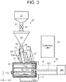
- FIG. 2 and FIG. 3 are sectional views showing states where the kneading vessel 11 is in the horizontally lying state shown on the left side in FIG. 1 .
- FIG. 4 is a sectional view showing a state where the kneading vessel 11 is in the vertically standing state shown on the right side in FIG. 1 .
- the core manufacturing apparatus according to the embodiment includes the kneading unit 10, the storage unit 20, the links L1, L2, and a control unit 30.
- the kneading unit 10 includes the kneading vessel 11, kneading rods 12, the turning support member 13, and the piston 14.
- the kneading vessel 11 is a tubular member that is fed with core sand S1 through a feed port 11a to which the storage unit 20 is coupled.
- the kneading vessel 11 has, for example, a cylindrical shape.
- the feed port 11a is provided on an upper side of the kneading vessel 11 in the horizontally lying state of the kneading vessel 11.
- the core sand S1 can be fed into the kneading vessel 11 by gravity.
- An ejection port 11b through which the kneaded core sand S1 is ejected is provided in one end surface, in a longitudinal direction, of the kneading vessel 11, and the piston 14 is provided on the other end surface.
- the ejection port 11b is provided so as to protrude from the end surface of the kneading vessel 11.
- a core forming mold (not shown) is coupled to the ejection port 11b.
- the core sand S1 fed into the kneading vessel 11 is kneaded along with a binder.
- the core sand S1 may be either natural sand or artificial sand.
- the binder is, for example, an inorganic binder containing liquid glass and water, but may instead be an organic binder.
- the binder is sprayed from a spraying device (not shown) provided on an inner circumferential surface of the kneading vessel 11.
- the spraying device is provided, for example, in the vicinity of the feed port 11a.
- the kneading rods 12 are provided inside the kneading vessel 11 so as to extend along substantially the entire length of the kneading vessel 11 in the longitudinal direction. There is a plurality of kneading rods 12, and these kneading rods 12 are fixed on, for example, a disc-shaped rotating base 12a.
- the rotating base 12a is provided inside the kneading vessel 11, at an end on the side of the piston 14, and rotates around an axis parallel to the longitudinal direction of the kneading vessel 11.
- the core sand S1 fed into the kneading vessel 11 is kneaded by the kneading rods 12.
- the kneading rods 12 are disposed, for example, in a radial arrangement centered on a rotational axis. Alternatively, the kneading rods 12 may be disposed in an S-shape so as to be point-symmetrical with the rotational axis as the center.
- the shape of the kneading rods 12 is not particularly limited as long as it is a columnar shape extending parallel to the rotational axis.
- the cross-sectional shape of the kneading rods 12 is, for example, a circular shape, but may instead be an elliptical shape, a polygonal shape, etc.
- the rotating base 12a is an external gear and driven to rotate by a driving source, such as a motor, through a gear disposed at a circumferential edge of the rotating base 12a.
- a driving source such as a motor
- the operation of this driving source is controlled by, for example, the control unit 30.
- the rotational axis of the rotating base 12a coincides with a central axis of the cylindrical kneading vessel 11 in this embodiment, but the present invention is not particularly limited to this arrangement.
- the kneading vessel 11 is supported so as to be turnable around the shaft (first shaft) A1 by the turning support member 13 through the link L1 fixed on the kneading vessel 11.
- the kneading vessel 11 is capable of transitioning between the horizontally lying state and the vertically standing state by turning 90° around the shaft A1.
- the kneading vessel 11 is driven to rotate by a driving source (not shown), such as a motor, coupled to the shaft A1.
- a driving source such as a motor
- the core sand S1 is fed into the kneading vessel 11 through the feed port 11a located on the upper side of the kneading vessel 11, and the fed core sand S1 is kneaded by the kneading rods 12.
- a valve V2 and a valve V3 to be described later are opened, the core sand S1 stored in the weigh hopper 22 is fed into the kneading vessel 11 by gravity.
- FIG. 2 shows a state where the valve V3 is closed
- FIG. 3 shows a state where the valve V3 is opened.
- the valves V2, V3 are closed except when the core sand S1 is fed.
- the core sand S1 is ejected downward (in the z-axis negative direction) and packed into a mold 40 by the piston 14.
- the mold 40 is composed of an upper mold 41 and a lower mold 42, with a cavity 43 formed therebetween.
- the core sand S1 ejected from the kneading vessel 11 by the piston 14 is packed into the cavity 43 to manufacture a core.
- This core is used, for example, to cast an on-board engine part.
- the piston 14 shown in the drawings is an electrically operated ball-screw piston, and includes a piston head 141, a piston rod 142, and a motor 143.
- the piston head 141 is housed inside the kneading vessel 11 and disposed closer to the ejection port 11b than the rotating base 12a is.
- the piston head 141 is driven by the motor 143 that is coupled to the piston head 141 through the piston rod 142 that extends through the end surface of the kneading vessel 11.
- the operation of the motor 143 is controlled by, for example, the control unit 30.
- the piston head 141 is on standby at an end of the kneading vessel 11 on the side of the piston 14.
- the piston head 141 advances in the longitudinal direction of the kneading vessel 11 and ejects the kneaded core sand S1 through the ejection port 11b.
- the core sand S1 is ejected with the kneading vessel 11 in the vertically standing state.
- FIG. 4 shows a state where the piston head 141 has descended and the core sand S1 has been ejected.
- a plug 11c made of rubber, for example, is mounted at a root of the ejection port 11b, i.e., on an inner end surface of the kneading vessel 11.
- the plug 11c can keep the core sand S1 fed into the kneading vessel 11 from leaking out of the kneading vessel 11.
- the plug 11c has an incision that has, for example, a cross shape as seen in a plan view and extends through a central portion of the plug 11c in a thickness direction thereof. Therefore, the plug 11c opens due to the incision when the core sand S1 inside the kneading vessel 11 is pressurized and ejected.
- the gap between the inner circumferential surface of the kneading vessel 11 and an outer circumferential surface of the piston head 141 is kept sealed by a seal member or the like.
- the piston head 141 has through-holes into which the kneading rods 12 are fitted and inserted.
- the gap between an inner circumferential surface of each of these through-holes and an outer circumferential surface of the kneading rod 12 is also kept sealed by a seal member or the like.
- This configuration allows the core sand S1 inside the kneading vessel 11 to be ejected through the ejection port 11b without leaking.
- the piston head 141 can rotate along with the kneading rods 12. While the piston 14 is an electrically operated piston here, the piston 14 is not limited thereto and may instead be a piston driven by air pressure, oil pressure, or the like.
- the storage unit 20 includes the preliminary tank 21, the weigh hopper 22, the support member 23, pipes P1 to P3, and valves V1 to V3.
- the preliminary tank 21 is a tank that temporarily stores the core sand S1 to be supplied to the weigh hopper 22.
- an upper part of the preliminary tank 21 has a cylindrical shape and a lower part thereof has an inverted conical shape.
- the core sand S1 is supplied to the preliminary tank 21 from a larger storage tank through a pipe etc.
- the preliminary tank 21 and the weigh hopper 22 are connected to each other by the pipe P1.
- the weigh hopper 22 is provided under the preliminary tank 21, and a lower portion of the preliminary tank 21 and an upper portion of the weigh hopper 22 are connected to each other by the pipe P1.
- the pipe P1 is provided with the valve V1.
- the valve V1 When the valve V1 is opened, the core sand S1 stored in the preliminary tank 21 is fed into the weigh hopper 22 by gravity.
- the amount of core sand S1 to be fed can be finely adjusted by adjusting the degree of opening of the valve V1.
- the degree of opening of the valve V1 is controlled by, for example, the control unit 30.
- the weigh hopper 22 stores a predetermined amount of core sand S1 that has been weighed to be fed into the kneading vessel 11.
- FIG. 5 is a detailed sectional view of the weigh hopper 22.
- the storage unit 20 includes a weigher 24 that measures the weight of the weigh hopper 22, and a weigher support member 25 that supports the weigher 24.
- the core sand S1 stored in the weigh hopper 22 is weighed while the core sand S1 is supplied to the weigh hopper 22.
- the core manufacturing apparatus simultaneously weighs and stores core sand and thereby achieves excellent productivity.
- the weigh hopper 22 includes a main body 221 and a lid 222.
- the main body 221 has an inverted conical shape, and includes a flange 221a that is provided on an outer circumferential surface at an upper portion of the main body 221 and protrudes outward.
- the lid 222 is a disc-shaped cover lid and fits on an upper end portion of the main body 221.
- a through-hole is provided at a central portion of the lid 222, and the pipe P1 is slidably fitted in the through-hole.
- the pipe P2 extends from a lower end of the main body 221. A lower end portion of the pipe P2 is slidably fitted in the pipe P3.
- the pipe P2 is provided with the valve V2.
- the valve V2 and the valve V3 to be described later are opened, the core sand S1 stored in the weigh hopper 22 is fed into the kneading vessel 11 by gravity.
- FIG. 3 shows the state where the valve V3 is opened. Opening and closing of the valve V2 and the valve V3 are controlled by, for example, the control unit 30.
- the weigher 24 is, for example, a load cell and measures the weight of the weigh hopper 22.
- the flange 221a of the weigh hopper 22 is placed on the weigher 24. Specifically, the weigher 24 is loaded with the weights of the weigh hopper 22 (the main body 221 and the lid 222), the core sand S1 inside the weigh hopper 22, the pipe P2, and the valve V2.
- the weigher 24 Since the pipe P1 is slidably fitted in the through-hole of the lid 222 as described above, the weigher 24 is not loaded with the weights of members located above the pipe P1. Since the pipe P2 is slidably fitted in the pipe P3, the weigher 24 is not loaded with the weights of members located under the pipe P3.
- the weight of the core sand S1 fed from the preliminary tank 21 into the weigh hopper 22 can be learned from the weight measured by the weigher 24. For example, based on the weight measured by the weigher 24, the control unit 30 controls the degree of opening of the valve V1 such that the weight of the core sand S1 inside the weigh hopper 22 meets a target value. For example, the control unit 30 decreases the degree of opening of the valve V1 as the weight of the core sand S1 approaches the target value. Under this control, the weight of the core sand S1 to be fed into the weigh hopper 22 can be accurately controlled.
- the weigher support member 25 includes a flat-plate-shaped platform 25a and pillars 25b that support the platform 25a.
- the weigher 24 is placed and fixed on the platform 25a.
- the pillars 25b are fixed on the support member 23. Therefore, the weigher 24 is supported by the support member 23 through the weigher support member 25.
- a through-hole 25c through which the main body 221 of the weigh hopper 22 is inserted is provided at a central portion of the platform 25a.
- the weigher support member 25 supports only the weigher 24 and does not directly support the weigh hopper 22. With this configuration, the weigher 24 is able to measure the weight of the weigh hopper 22.
- the weigher 24 supports the weigh hopper 22 while measuring the weight of the weigh hopper 22. Therefore, the weigher support member 25 supports the weigh hopper 22 through the weigher 24. The support member 23 supports the weigh hopper 22 through the weigher support member 25 and the weigher 24.
- the support member 23 indirectly supports the weigh hopper 22. Similarly, the support member 23 indirectly supports the preliminary tank 21 through a support member (not shown). This is why the posture of the storage unit 20 depends on the support member 23.
- the support member 23 is coupled to the link L1 so as to be turnable around the shaft (second shaft) A2. Since the link L1 is fixed on the kneading vessel 11, the support member 23 is coupled to the kneading vessel 11 so as to be turnable around the shaft A2. The support member 23 is coupled to the link L2 so as to be turnable around the shaft A4. The link L2 is coupled to the turning support member 13 so as to be turnable around the shaft A3.
- the turning support member 13, the support member 23, and the links L1, L2 constitute a parallel linkage having the four shafts A1 to A4 as joints.
- the turning support member 13 is fixed on the ground and corresponds to a fixed link in the parallel linkage.
- the link L1 fixed on the kneading vessel 11 corresponds to a driver.
- the link L2 and the support member 23 correspond to a follower and a connector, respectively.
- the core manufacturing apparatus keeps the storage unit 20 coupled to the kneading vessel 11 in the same posture while the kneading vessel 11 turns. It is not necessary to uncouple the storage unit 20 from the kneading vessel 11 when the kneading vessel 11 turns. By thus eliminating the need for uncoupling and coupling actions, this apparatus achieves excellent core productivity.
- the pipe P3 is fixed on the support member 23.
- the pipe P2 is fitted at one end of the pipe P3 as described above, and the valve V3 is disposed at the other end of the pipe P3.
- the shape of the other end of the pipe P3 is adapted to the surface shape of the valve V3 so as to keep the core sand S1 from leaking.
- the valve V3 is supported by the support member 23 shown in FIG. 1 so as to be turnable around the turning shaft A2 of the support member 23.
- the valve V3 can turn around the shaft A2 relatively to the support member 23, and can also turn around the shaft A2 along with the support member 23 relatively to the kneading vessel 11.
- the valve V3 opens and closes the feed port 11a with the kneading vessel 11 in the horizontally lying state by turning around the shaft A2 relatively to the support member 23 while remaining in contact with the feed port 11a.
- the support member 23 i.e., the storage unit 20
- the support member 23 can maintain the same posture with the valve V3 in contact with the feed port 11a while the kneading vessel 11 turns.
- the feed port 11a can be sealed by the same valve V3 both when the kneading vessel 11 is in the horizontally lying state and when the kneading vessel 11 is in the vertically standing state.
- the turning actions (i.e., opening and closing) of the valve V3 relatively to the support member 23 are controlled by, for example, the control unit 30.
- the valve V3 shown in FIG. 2 to FIG. 4 has a cut-off spherical shape obtained by cutting off, by a plane, a portion of the valve V3 that does not come into contact with the feed port 11a, but may instead have a shape of a perfect sphere.
- This cut-off spherical shape can reduce the size and weight of the valve V3. Since a part of the valve V3 has an arc shape, the feed port 11a has a substantially circular shape.
- the valve V3 is made of a resin, for example, but may instead be made of a metal etc.
- the valve V3 is made of an abrasion-resistant resin, such as fluorine resin, super-high-molecular polyethylene, polyacetal, or polyamide.
- FIG. 6 is a detailed sectional view of the valve V3 and the feed port 11a.
- FIG. 6 corresponds to an enlarged view of FIG. 2 .
- the valve V3 is in contact with the feed port 11a of which a circumferential edge is covered with a seal member SL1, which has an annular shape and made of a resin. With this configuration, the sealing of the gap between the valve V3 and the feed port 11a is kept.
- the resin seal member SL1 is made of an abrasion-resistant resin, such as fluorine resin, super-high-molecular polyethylene, polyacetal, or polyamide.
- valve V3 and the resin seal member SL1 may be made of different resins.
- the valve V3 may be made of fluorine resin and the resin seal member SL1 may be made of super-high-molecular polyethylene.
- the resin seal member SL1 is provided so as to protrude from the circumferential edge of the feed port 11a toward a center side.
- a portion of the resin seal member SL1 that protrudes toward the center side of the feed port 11a has a triangular cross-sectional shape, with the thickness decreasing gradually toward the center of the feed port 11a. This allows the resin seal member SL1 to come into close contact with the valve V3 easily.
- an annular groove SL1a extending along the circumferential edge of the feed port 11a is provided in the resin seal member SL1, at a side facing the outer circumferential surface of the kneading vessel 11. Since the thickness of the resin seal member SL1 decreases gradually toward the center of the feed port 11a as described above, the groove SL1a also has a triangular cross-sectional shape. A portion of the resin seal member SL1 where the groove SL1a is formed has a substantially constant small thickness and deforms easily. Therefore, the resin seal member SL1 can come easily into close contact with the valve V3 and also easily absorb thermal expansion of the valve V3. Thus, providing the groove SL1a contributes to sealing the gap between the valve V3 and the feed port 11a more effectively.
- a flat-plate-shaped annular rubber packing SL2 is provided between the resin seal member SL1 and the outer circumferential surface of the kneading vessel 11.
- Providing the rubber packing SL2 allows the resin seal member SL1 to come into close contact with the valve V3 more easily and also to absorb thermal expansion of the valve V3.
- the rubber packing SL2 contributes to sealing the gap between the valve V3 and the feed port 11a even more effectively.
- the rubber packing SL2 is made of, for example, silicone rubber.
- a through-hole V3a perpendicular to the turning shaft A2 of the valve V3 is formed inside the valve V3.
- the valve V3 is closed and the feed port 11a of the kneading vessel 11 is closed with the valve V3.
- the valve V3 has opened by turning around the shaft A2 from the state shown in FIG. 2 .
- the pipe P3 and the feed port 11a of the kneading vessel 11 are connected to each other through the through-hole V3a inside the valve V3, so that the core sand S1 can be fed into the kneading vessel 11.
- the valve V3 is closed to thereby keep moisture inside the kneading vessel 11 from entering the pipe P3.
- the control unit 30 shown in FIG. 2 to FIG. 4 controls all actions in the core manufacturing apparatus, including the turning actions of the kneading vessel 11, the rotating actions of the kneading rods 12, the actions of the piston 14, the opening and closing actions of the valves V1 to V3, and adjustment of the degrees of opening of the valves.
- the control unit 30 may be divided into a plurality of units and provided as such.
- the control unit 30 functions as a computer and includes, for example, a computing part, such as a central processing unit (CPU), and a storing part, such as a random-access memory (RAM) or a read-only memory (ROM), that stores various control programs, data, etc.
- a computing part such as a central processing unit (CPU)
- RAM random-access memory
- ROM read-only memory
- the storage unit 20 is coupled to the kneading vessel 11 so as to be turnable around the shaft A2, and the storage unit 20 remains coupled to the kneading vessel 11 in the same posture while the kneading vessel 11 turns. It is not necessary to uncouple the storage unit 20 from the kneading vessel 11 when the kneading vessel 11 turns. By thus eliminating the need for uncoupling and coupling actions, this apparatus achieves excellent core productivity.
- the storage unit 20 includes the valve V3 having a spherical shape or a cut-off spherical shape that opens and closes the feed port 11a with the kneading vessel 11 in the horizontally lying state by turning around the shaft A2 while remaining in contact with the feed port 11a. Therefore, as shown in FIG. 2 and FIG. 4 , the storage unit 20 can maintain the same posture with the valve V3 in contact with the feed port 11a while the kneading vessel 11 turns. Thus, the feed port 11a can be sealed by the same valve V3 both when the kneading vessel 11 is in the horizontally lying state and when the kneading vessel 11 is in the vertically standing state.
- the present invention is not limited to the above embodiment but can be changed as necessary within the scope of the gist of the invention.
Landscapes
- Engineering & Computer Science (AREA)
- Mechanical Engineering (AREA)
- Molds, Cores, And Manufacturing Methods Thereof (AREA)
- Casting Devices For Molds (AREA)
- Processing And Handling Of Plastics And Other Materials For Molding In General (AREA)
Abstract
Description
- The present invention relates to a core manufacturing apparatus.
- There are known core manufacturing apparatuses that manufacture cores by kneading core sand along with a binder etc. in a kneading vessel and ejecting and packing the kneaded core sand (kneaded sand) into a mold. A core manufacturing apparatus developed by the present inventors kneads core sand with the kneading vessel in a horizontally lying state, as disclosed in Japanese Patent Application Publication No.
2017-131913 JP 2017-131913 A - Therefore, the present inventors developed another core manufacturing apparatus that kneads core sand with the kneading vessel in a horizontally lying state and then brings the kneading vessel into a vertically standing state to eject the kneaded sand downward and pack it into a mold, as disclosed in Japanese Patent Application Publication No.
2019-202323 JP 2019-202323 A - In the core manufacturing apparatuses disclosed in
JP 2017-131913 A JP 2019-202323 A JP 2017-131913 A JP 2019-202323 A - The core manufacturing apparatus disclosed in
JP 2019-202323 A - The present invention provides a core manufacturing apparatus in which the feed port of the kneading vessel can be sealed by the same valve both when the kneading vessel is in a horizontally lying state and when it is in a vertically standing state.
- A core manufacturing apparatus as one aspect of the present invention includes: a storage unit configured to store core sand; a kneading vessel, which is tubular, configured to be fed with the core sand though a feed port to which the storage unit is coupled; a kneading rod provided inside the kneading vessel so as to extend in a longitudinal direction of the kneading vessel, and configured to knead the core sand by rotating around an axis parallel to the longitudinal direction; and a piston configured to eject the kneaded core sand from one end, in the longitudinal direction, of the kneading vessel. The kneading vessel is configured to be able to transition between a horizontally lying state and a vertically standing state by turning around a first shaft. The kneading vessel is configured to be fed with the core sand in the horizontally lying state through the feed port that is located on the upper side of the kneading vessel. The piston is configured to eject the core sand downward and pack the core sand into a mold with the kneading vessel in the vertically standing state. The storage unit includes a valve that opens and closes the feed port with the kneading vessel in the horizontally lying state by turning around a second shaft parallel to the first shaft while remaining in contact with the feed port. A part of the valve has an arc shape. The storage unit is coupled to the kneading vessel so as to be turnable around the second shaft, and is configured to maintain the same posture with the valve in contact with the feed port while the kneading vessel turns.
- With the above aspect, the feed port can be sealed by the same valve both when the kneading vessel is in the horizontally lying state and when it is in the vertically standing state.
- In the above aspect, the core manufacturing apparatus may include a parallel linkage having a driver that has the first shaft and the second shaft as joints. With the above configuration, the core manufacturing apparatus is excellent in maintainability.
- In the above aspect, the valve may be made of a resin.
- In the above aspect, the valve may be in contact with the feed port of which a circumferential edge is covered with a seal member having an annular shape and made of a resin. With the above configuration, the sealing of the gap between the valve and the feed port can be improved.
- In the above aspect, the valve and the seal member may be made of different resins. With the above configuration, the adhesion between the valve and the feed port can be reduced.
- In the above aspect, an annular groove extending along the circumferential edge of the feed port may be provided in the resin seal member, at a side facing an outer circumferential surface of the kneading vessel.
- In the above aspect, a rubber packing may be provided between the seal member and an outer circumferential surface of the kneading vessel. With the above configuration, the sealing of the gap between the valve and the feed port can be further improved.
- In the above aspect, the valve may have a cut-off spherical shape obtained by cutting off a portion of the valve that does not come into contact with the feed port. With the above configuration, the size and weight of the valve can be reduced.
- In the above aspect, the valve may have a spherical shape.
- In the above aspect, a through-hole perpendicular to the second shaft may be formed inside the valve.
- In the above aspect, the storage unit may include a hopper that stores a predetermined amount of core sand to be fed into the kneading vessel, and a weigher configured to measure the weight of the hopper. The weigher may be configured to measure the weight of the core sand stored in the hopper while the core sand is supplied to the hopper. With the above configuration, the core manufacturing apparatus is capable of simultaneously weighing and storing core sand and thereby achieves excellent productivity.
- In the above aspect, the storage unit may include a preliminary tank that stores the core sand to be supplied to the hopper, and a valve provided on a pipe connecting the preliminary tank and the hopper to each other. When the core sand is supplied from the preliminary tank to the hopper, the degree of opening of the valve provided on the pipe may be adjusted based on the weight of the hopper measured by the weigher. With the above configuration, the core manufacturing apparatus can accurately control the weight of core sand to be fed into the weigh hopper.
- In the above aspect, the valve configured to open and close the feed port may be made of an abrasion-resistant resin, and the seal member may be made of an abrasion-resistant resin.
- With the above aspect, the present invention can provide a core manufacturing apparatus in which the feed port of the kneading vessel can be sealed by the same valve both when the kneading vessel is in the horizontally lying state and when it is in the vertically standing state.
- Features, advantages, and technical and industrial significance of exemplary embodiments of the invention will be described below with reference to the accompanying drawings, in which like numerals denote like elements, and wherein:
-
FIG. 1 is side views showing actions of a core manufacturing apparatus according to an embodiment; -
FIG. 2 is a sectional view of the core manufacturing apparatus according to the embodiment; -
FIG. 3 is a sectional view of the core manufacturing apparatus according to the embodiment; -
FIG. 4 is a sectional view of the core manufacturing apparatus according to the embodiment; -
FIG. 5 is a detailed sectional view of aweigh hopper 22; and -
FIG. 6 is a detailed sectional view of a valve V3 and afeed port 11a. - A specific embodiment to which the present invention is applied will be described in detail below with reference to the drawings. It is not intended that the present invention is limited to the following embodiment. To clarify the illustration, the following description and drawings are simplified as necessary.
- First, the overall configuration and actions of a core manufacturing apparatus according to the embodiment will be described with reference to
FIG. 1. FIG. 1 is side views showing the actions of the core manufacturing apparatus according to the embodiment. It should be understood that the right-handed xyz-orthogonal coordinate system shown inFIG. 1 and the other drawings is for the convenience of illustrating the positional relationship among components. Normally, a z-axis positive direction is a vertically upward direction and an xy-plane is a horizontal plane, which applies to all the drawings. - As shown in
FIG. 1 , the core manufacturing apparatus according to the embodiment includes akneading unit 10, astorage unit 20, and links L1, L2. A brief overview of each component will be given here with reference toFIG. 1 , and details thereof will be given later. The kneadingunit 10 includes a kneadingvessel 11 that is fed with core sand and kneads the core sand, a turningsupport member 13 that supports the kneadingvessel 11, and apiston 14 that ejects the kneaded core sand. Thestorage unit 20 includes apreliminary tank 21 that temporarily stores core sand, aweigh hopper 22 that stores, while weighing, a predetermined amount of core sand to be fed into the kneadingvessel 11, and asupport member 23 that supports thepreliminary tank 21 and theweigh hopper 22. - Here, the kneading
vessel 11 is supported so as to be turnable around a shaft (first shaft) A1 by the turningsupport member 13 through the link L1 fixed on the kneadingvessel 11. As shown inFIG. 1 , the kneadingvessel 11 is capable of transitioning between a horizontally lying state and a vertically standing state by turning 90° around the shaft A1. In the horizontally lying state shown on the left side inFIG. 1 , core sand is fed from theweigh hopper 22 into the kneadingvessel 11 and the fed core sand is kneaded. Then, in the vertically standing state shown on the right side inFIG. 1 , the core sand is ejected downward (in a z-axis negative direction) and packed into a mold by thepiston 14. Shown at the center inFIG. 1 is a state where the kneadingvessel 11 is in transition from the horizontally lying state to the vertically standing state or from the vertically standing state to the horizontally lying state. - As will be described in detail later, the posture of the
storage unit 20 depends on thesupport member 23. As shown inFIG. 1 , thesupport member 23 is coupled to the link L1 so as to be turnable around a shaft (second shaft) A2. Since the link L1 is fixed on the kneadingvessel 11, the support member 23 (i.e., the storage unit 20) is coupled to the kneadingvessel 11 so as to be turnable around the shaft A2. The link L2 is coupled to the turningsupport member 13 so as to be turnable around a shaft A3 and coupled to thesupport member 23 so as to be turnable around a shaft A4. - Here, the turning
support member 13, thesupport member 23, and the links L1, L2 constitute a parallel linkage having the four shafts A1 to A4 as joints. In the example ofFIG. 1 , the turningsupport member 13 is fixed on the ground and corresponds to a fixed link in the parallel linkage. The link L1 fixed on the kneadingvessel 11 corresponds to a driver. The link L2 and thesupport member 23 correspond to a follower and a connector, respectively. - Thus configured, the core manufacturing apparatus according to the embodiment keeps the
storage unit 20 coupled to the kneadingvessel 11 in the same posture while the kneadingvessel 11 turns. It is not necessary to uncouple thestorage unit 20 from the kneadingvessel 11 when the kneadingvessel 11 turns. By thus eliminating the need for uncoupling and coupling actions, this apparatus achieves excellent core productivity. - As long as the requirement that the link L1 fixed on the kneading
vessel 11 should constitute a driver is met, thesupport member 23 may constitute a fixed link and the turningsupport member 13 may constitute a connector. Thestorage unit 20 is required to be coupled to the kneadingvessel 11 so as to be turnable around the shaft A2 parallel to the turning shaft A1 of the kneadingvessel 11, and to remain coupled to the kneadingvessel 11 in the same posture while the kneadingvessel 11 turns. As long as this requirement is met, thestorage unit 20 may be kept in the same posture by connecting the shafts A1, A2 to each other by a belt or a gear instead of the parallel linkage. However, compared with the means using a belt or a gear, a parallel linkage is less likely to fail when core sand sticks thereto and is excellent in maintainability. - Next, each component of the core manufacturing apparatus according to the embodiment will be described in detail with reference to
FIG. 1 to FIG. 4. FIG. 2 to FIG. 4 are sectional views of the core manufacturing apparatus according to the embodiment.FIG. 2 andFIG. 3 are sectional views showing states where the kneadingvessel 11 is in the horizontally lying state shown on the left side inFIG. 1 .FIG. 4 is a sectional view showing a state where the kneadingvessel 11 is in the vertically standing state shown on the right side inFIG. 1 . As shown inFIG. 2 to FIG. 4 , the core manufacturing apparatus according to the embodiment includes the kneadingunit 10, thestorage unit 20, the links L1, L2, and acontrol unit 30. - The configuration of the kneading
unit 10 will be described. As shown inFIG. 2 to FIG. 4 , the kneadingunit 10 includes the kneadingvessel 11, kneadingrods 12, the turningsupport member 13, and thepiston 14. The kneadingvessel 11 is a tubular member that is fed with core sand S1 through afeed port 11a to which thestorage unit 20 is coupled. The kneadingvessel 11 has, for example, a cylindrical shape. As shown inFIG. 2 andFIG. 3 , thefeed port 11a is provided on an upper side of the kneadingvessel 11 in the horizontally lying state of the kneadingvessel 11. Thus, the core sand S1 can be fed into the kneadingvessel 11 by gravity. - An
ejection port 11b through which the kneaded core sand S1 is ejected is provided in one end surface, in a longitudinal direction, of the kneadingvessel 11, and thepiston 14 is provided on the other end surface. In the shown example, theejection port 11b is provided so as to protrude from the end surface of the kneadingvessel 11. When ejecting the core sand S1, a core forming mold (not shown) is coupled to theejection port 11b. - The core sand S1 fed into the kneading
vessel 11 is kneaded along with a binder. The core sand S1 may be either natural sand or artificial sand. The binder is, for example, an inorganic binder containing liquid glass and water, but may instead be an organic binder. The binder is sprayed from a spraying device (not shown) provided on an inner circumferential surface of the kneadingvessel 11. The spraying device is provided, for example, in the vicinity of thefeed port 11a. - The kneading
rods 12 are provided inside the kneadingvessel 11 so as to extend along substantially the entire length of the kneadingvessel 11 in the longitudinal direction. There is a plurality of kneadingrods 12, and these kneadingrods 12 are fixed on, for example, a disc-shaped rotatingbase 12a. The rotatingbase 12a is provided inside the kneadingvessel 11, at an end on the side of thepiston 14, and rotates around an axis parallel to the longitudinal direction of the kneadingvessel 11. Thus, the core sand S1 fed into the kneadingvessel 11 is kneaded by the kneadingrods 12. - The kneading
rods 12 are disposed, for example, in a radial arrangement centered on a rotational axis. Alternatively, the kneadingrods 12 may be disposed in an S-shape so as to be point-symmetrical with the rotational axis as the center. The shape of the kneadingrods 12 is not particularly limited as long as it is a columnar shape extending parallel to the rotational axis. The cross-sectional shape of the kneadingrods 12 is, for example, a circular shape, but may instead be an elliptical shape, a polygonal shape, etc. - Although this is not shown, the rotating
base 12a is an external gear and driven to rotate by a driving source, such as a motor, through a gear disposed at a circumferential edge of therotating base 12a. The operation of this driving source is controlled by, for example, thecontrol unit 30. The rotational axis of therotating base 12a coincides with a central axis of thecylindrical kneading vessel 11 in this embodiment, but the present invention is not particularly limited to this arrangement. - As described above and shown in
FIG. 1 , the kneadingvessel 11 is supported so as to be turnable around the shaft (first shaft) A1 by the turningsupport member 13 through the link L1 fixed on the kneadingvessel 11. As shown inFIG. 1 , the kneadingvessel 11 is capable of transitioning between the horizontally lying state and the vertically standing state by turning 90° around the shaft A1. The kneadingvessel 11 is driven to rotate by a driving source (not shown), such as a motor, coupled to the shaft A1. The operation of this driving source is controlled by, for example, thecontrol unit 30. - As shown in
FIG. 2 andFIG. 3 , with the kneadingvessel 11 in the horizontally lying state, the core sand S1 is fed into the kneadingvessel 11 through thefeed port 11a located on the upper side of the kneadingvessel 11, and the fed core sand S1 is kneaded by the kneadingrods 12. When a valve V2 and a valve V3 to be described later are opened, the core sand S1 stored in theweigh hopper 22 is fed into the kneadingvessel 11 by gravity.FIG. 2 shows a state where the valve V3 is closed, andFIG. 3 shows a state where the valve V3 is opened. To keep moisture inside the kneadingvessel 11, the valves V2, V3 are closed except when the core sand S1 is fed. - As shown in
FIG. 4 , with the kneadingvessel 11 in the vertically standing state, the core sand S1 is ejected downward (in the z-axis negative direction) and packed into amold 40 by thepiston 14. In the shown example, themold 40 is composed of anupper mold 41 and alower mold 42, with a cavity 43 formed therebetween. The core sand S1 ejected from the kneadingvessel 11 by thepiston 14 is packed into the cavity 43 to manufacture a core. This core is used, for example, to cast an on-board engine part. - The
piston 14 shown in the drawings is an electrically operated ball-screw piston, and includes apiston head 141, apiston rod 142, and amotor 143. Thepiston head 141 is housed inside the kneadingvessel 11 and disposed closer to theejection port 11b than the rotatingbase 12a is. Thepiston head 141 is driven by themotor 143 that is coupled to thepiston head 141 through thepiston rod 142 that extends through the end surface of the kneadingvessel 11. The operation of themotor 143 is controlled by, for example, thecontrol unit 30. - Except during ejection, the
piston head 141 is on standby at an end of the kneadingvessel 11 on the side of thepiston 14. During ejection, thepiston head 141 advances in the longitudinal direction of the kneadingvessel 11 and ejects the kneaded core sand S1 through theejection port 11b. As described above and shown inFIG. 4 , the core sand S1 is ejected with the kneadingvessel 11 in the vertically standing state.FIG. 4 shows a state where thepiston head 141 has descended and the core sand S1 has been ejected. - A
plug 11c made of rubber, for example, is mounted at a root of theejection port 11b, i.e., on an inner end surface of the kneadingvessel 11. Theplug 11c can keep the core sand S1 fed into the kneadingvessel 11 from leaking out of the kneadingvessel 11. On the other hand, theplug 11c has an incision that has, for example, a cross shape as seen in a plan view and extends through a central portion of theplug 11c in a thickness direction thereof. Therefore, theplug 11c opens due to the incision when the core sand S1 inside the kneadingvessel 11 is pressurized and ejected. - The gap between the inner circumferential surface of the kneading
vessel 11 and an outer circumferential surface of thepiston head 141 is kept sealed by a seal member or the like. Thepiston head 141 has through-holes into which the kneadingrods 12 are fitted and inserted. The gap between an inner circumferential surface of each of these through-holes and an outer circumferential surface of the kneadingrod 12 is also kept sealed by a seal member or the like. This configuration allows the core sand S1 inside the kneadingvessel 11 to be ejected through theejection port 11b without leaking. Thepiston head 141 can rotate along with the kneadingrods 12. While thepiston 14 is an electrically operated piston here, thepiston 14 is not limited thereto and may instead be a piston driven by air pressure, oil pressure, or the like. - Next, the configuration of the
storage unit 20 will be described. As shown inFIG. 2 to FIG. 4 , thestorage unit 20 includes thepreliminary tank 21, theweigh hopper 22, thesupport member 23, pipes P1 to P3, and valves V1 to V3. - The
preliminary tank 21 is a tank that temporarily stores the core sand S1 to be supplied to theweigh hopper 22. In the shown example, an upper part of thepreliminary tank 21 has a cylindrical shape and a lower part thereof has an inverted conical shape. Although this is not shown, the core sand S1 is supplied to thepreliminary tank 21 from a larger storage tank through a pipe etc. Thepreliminary tank 21 and theweigh hopper 22 are connected to each other by the pipe P1. - The
weigh hopper 22 is provided under thepreliminary tank 21, and a lower portion of thepreliminary tank 21 and an upper portion of theweigh hopper 22 are connected to each other by the pipe P1. The pipe P1 is provided with the valve V1. When the valve V1 is opened, the core sand S1 stored in thepreliminary tank 21 is fed into theweigh hopper 22 by gravity. The amount of core sand S1 to be fed can be finely adjusted by adjusting the degree of opening of the valve V1. As will be described later in detail, the degree of opening of the valve V1 is controlled by, for example, thecontrol unit 30. - The
weigh hopper 22 stores a predetermined amount of core sand S1 that has been weighed to be fed into the kneadingvessel 11. Here,FIG. 5 is a detailed sectional view of theweigh hopper 22. As shown inFIG. 5 , thestorage unit 20 includes aweigher 24 that measures the weight of theweigh hopper 22, and aweigher support member 25 that supports theweigher 24. The core sand S1 stored in theweigh hopper 22 is weighed while the core sand S1 is supplied to theweigh hopper 22. Thus, the core manufacturing apparatus simultaneously weighs and stores core sand and thereby achieves excellent productivity. - The
weigh hopper 22 includes amain body 221 and a lid 222. Themain body 221 has an inverted conical shape, and includes aflange 221a that is provided on an outer circumferential surface at an upper portion of themain body 221 and protrudes outward. The lid 222 is a disc-shaped cover lid and fits on an upper end portion of themain body 221. A through-hole is provided at a central portion of the lid 222, and the pipe P1 is slidably fitted in the through-hole. - The pipe P2 extends from a lower end of the
main body 221. A lower end portion of the pipe P2 is slidably fitted in the pipe P3. The pipe P2 is provided with the valve V2. When the valve V2 and the valve V3 to be described later are opened, the core sand S1 stored in theweigh hopper 22 is fed into the kneadingvessel 11 by gravity. As described above,FIG. 3 shows the state where the valve V3 is opened. Opening and closing of the valve V2 and the valve V3 are controlled by, for example, thecontrol unit 30. - The
weigher 24 is, for example, a load cell and measures the weight of theweigh hopper 22. Theflange 221a of theweigh hopper 22 is placed on theweigher 24. Specifically, theweigher 24 is loaded with the weights of the weigh hopper 22 (themain body 221 and the lid 222), the core sand S1 inside theweigh hopper 22, the pipe P2, and the valve V2. - Since the pipe P1 is slidably fitted in the through-hole of the lid 222 as described above, the
weigher 24 is not loaded with the weights of members located above the pipe P1. Since the pipe P2 is slidably fitted in the pipe P3, theweigher 24 is not loaded with the weights of members located under the pipe P3. - The weight of the core sand S1 fed from the
preliminary tank 21 into theweigh hopper 22 can be learned from the weight measured by theweigher 24. For example, based on the weight measured by theweigher 24, thecontrol unit 30 controls the degree of opening of the valve V1 such that the weight of the core sand S1 inside theweigh hopper 22 meets a target value. For example, thecontrol unit 30 decreases the degree of opening of the valve V1 as the weight of the core sand S1 approaches the target value. Under this control, the weight of the core sand S1 to be fed into theweigh hopper 22 can be accurately controlled. - As shown in
FIG. 5 , theweigher support member 25 includes a flat-plate-shapedplatform 25a andpillars 25b that support theplatform 25a. Theweigher 24 is placed and fixed on theplatform 25a. Thepillars 25b are fixed on thesupport member 23. Therefore, theweigher 24 is supported by thesupport member 23 through theweigher support member 25. - A through-
hole 25c through which themain body 221 of theweigh hopper 22 is inserted is provided at a central portion of theplatform 25a. Thus, theweigher support member 25 supports only theweigher 24 and does not directly support theweigh hopper 22. With this configuration, theweigher 24 is able to measure the weight of theweigh hopper 22. - On the other hand, the
weigher 24 supports theweigh hopper 22 while measuring the weight of theweigh hopper 22. Therefore, theweigher support member 25 supports theweigh hopper 22 through theweigher 24. Thesupport member 23 supports theweigh hopper 22 through theweigher support member 25 and theweigher 24. - Thus, the
support member 23 indirectly supports theweigh hopper 22. Similarly, thesupport member 23 indirectly supports thepreliminary tank 21 through a support member (not shown). This is why the posture of thestorage unit 20 depends on thesupport member 23. - Here, as shown in
FIG. 1 , thesupport member 23 is coupled to the link L1 so as to be turnable around the shaft (second shaft) A2. Since the link L1 is fixed on the kneadingvessel 11, thesupport member 23 is coupled to the kneadingvessel 11 so as to be turnable around the shaft A2. Thesupport member 23 is coupled to the link L2 so as to be turnable around the shaft A4. The link L2 is coupled to the turningsupport member 13 so as to be turnable around the shaft A3. - As described above and shown in
FIG. 1 , the turningsupport member 13, thesupport member 23, and the links L1, L2 constitute a parallel linkage having the four shafts A1 to A4 as joints. In the example ofFIG. 1 , the turningsupport member 13 is fixed on the ground and corresponds to a fixed link in the parallel linkage. The link L1 fixed on the kneadingvessel 11 corresponds to a driver. The link L2 and thesupport member 23 correspond to a follower and a connector, respectively. - Thus configured, the core manufacturing apparatus according to the embodiment keeps the
storage unit 20 coupled to the kneadingvessel 11 in the same posture while the kneadingvessel 11 turns. It is not necessary to uncouple thestorage unit 20 from the kneadingvessel 11 when the kneadingvessel 11 turns. By thus eliminating the need for uncoupling and coupling actions, this apparatus achieves excellent core productivity. - Referring back to
FIG. 2 to FIG. 4 , the description continues. The pipe P3 is fixed on thesupport member 23. The pipe P2 is fitted at one end of the pipe P3 as described above, and the valve V3 is disposed at the other end of the pipe P3. The shape of the other end of the pipe P3 is adapted to the surface shape of the valve V3 so as to keep the core sand S1 from leaking. - The valve V3 is supported by the
support member 23 shown inFIG. 1 so as to be turnable around the turning shaft A2 of thesupport member 23. Thus, the valve V3 can turn around the shaft A2 relatively to thesupport member 23, and can also turn around the shaft A2 along with thesupport member 23 relatively to the kneadingvessel 11. As shown inFIG. 2 andFIG. 3 , the valve V3 opens and closes thefeed port 11a with the kneadingvessel 11 in the horizontally lying state by turning around the shaft A2 relatively to thesupport member 23 while remaining in contact with thefeed port 11a. - As shown in
FIG. 2 andFIG. 4 , the support member 23 (i.e., the storage unit 20) can maintain the same posture with the valve V3 in contact with thefeed port 11a while the kneadingvessel 11 turns. Thus, thefeed port 11a can be sealed by the same valve V3 both when the kneadingvessel 11 is in the horizontally lying state and when the kneadingvessel 11 is in the vertically standing state. The turning actions (i.e., opening and closing) of the valve V3 relatively to thesupport member 23 are controlled by, for example, thecontrol unit 30. - The valve V3 shown in
FIG. 2 to FIG. 4 has a cut-off spherical shape obtained by cutting off, by a plane, a portion of the valve V3 that does not come into contact with thefeed port 11a, but may instead have a shape of a perfect sphere. This cut-off spherical shape can reduce the size and weight of the valve V3. Since a part of the valve V3 has an arc shape, thefeed port 11a has a substantially circular shape. The valve V3 is made of a resin, for example, but may instead be made of a metal etc. For example, the valve V3 is made of an abrasion-resistant resin, such as fluorine resin, super-high-molecular polyethylene, polyacetal, or polyamide. - Here,
FIG. 6 is a detailed sectional view of the valve V3 and thefeed port 11a.FIG. 6 corresponds to an enlarged view ofFIG. 2 . As shown inFIG. 6 , the valve V3 is in contact with thefeed port 11a of which a circumferential edge is covered with a seal member SL1, which has an annular shape and made of a resin. With this configuration, the sealing of the gap between the valve V3 and thefeed port 11a is kept. Like the valve V3, the resin seal member SL1 is made of an abrasion-resistant resin, such as fluorine resin, super-high-molecular polyethylene, polyacetal, or polyamide. To reduce adhesion between the valve V3 and the resin seal member SL1, for example, the valve V3 and the resin seal member SL1 may be made of different resins. For example, the valve V3 may be made of fluorine resin and the resin seal member SL1 may be made of super-high-molecular polyethylene. - In the example of
FIG. 6 , the resin seal member SL1 is provided so as to protrude from the circumferential edge of thefeed port 11a toward a center side. A portion of the resin seal member SL1 that protrudes toward the center side of thefeed port 11a has a triangular cross-sectional shape, with the thickness decreasing gradually toward the center of thefeed port 11a. This allows the resin seal member SL1 to come into close contact with the valve V3 easily. - In the example of
FIG. 6 , an annular groove SL1a extending along the circumferential edge of thefeed port 11a is provided in the resin seal member SL1, at a side facing the outer circumferential surface of the kneadingvessel 11. Since the thickness of the resin seal member SL1 decreases gradually toward the center of thefeed port 11a as described above, the groove SL1a also has a triangular cross-sectional shape. A portion of the resin seal member SL1 where the groove SL1a is formed has a substantially constant small thickness and deforms easily. Therefore, the resin seal member SL1 can come easily into close contact with the valve V3 and also easily absorb thermal expansion of the valve V3. Thus, providing the groove SL1a contributes to sealing the gap between the valve V3 and thefeed port 11a more effectively. - Further, in the example of
FIG. 6 , a flat-plate-shaped annular rubber packing SL2 is provided between the resin seal member SL1 and the outer circumferential surface of the kneadingvessel 11. Providing the rubber packing SL2 allows the resin seal member SL1 to come into close contact with the valve V3 more easily and also to absorb thermal expansion of the valve V3. Thus, providing the rubber packing SL2 contributes to sealing the gap between the valve V3 and thefeed port 11a even more effectively. The rubber packing SL2 is made of, for example, silicone rubber. - As shown in
FIG. 6 , a through-hole V3a perpendicular to the turning shaft A2 of the valve V3 is formed inside the valve V3. In the state shown inFIG. 2 (FIG. 6 ), the valve V3 is closed and thefeed port 11a of the kneadingvessel 11 is closed with the valve V3. On the other hand, in the state shown inFIG. 3 , the valve V3 has opened by turning around the shaft A2 from the state shown inFIG. 2 . In this state, the pipe P3 and thefeed port 11a of the kneadingvessel 11 are connected to each other through the through-hole V3a inside the valve V3, so that the core sand S1 can be fed into the kneadingvessel 11. Except when the core sand S1 is fed, the valve V3 is closed to thereby keep moisture inside the kneadingvessel 11 from entering the pipe P3. - The
control unit 30 shown inFIG. 2 to FIG. 4 controls all actions in the core manufacturing apparatus, including the turning actions of the kneadingvessel 11, the rotating actions of the kneadingrods 12, the actions of thepiston 14, the opening and closing actions of the valves V1 to V3, and adjustment of the degrees of opening of the valves. Thecontrol unit 30 may be divided into a plurality of units and provided as such. Although this is not shown, thecontrol unit 30 functions as a computer and includes, for example, a computing part, such as a central processing unit (CPU), and a storing part, such as a random-access memory (RAM) or a read-only memory (ROM), that stores various control programs, data, etc. - As has been described above, in the core manufacturing apparatus according to the embodiment, the
storage unit 20 is coupled to the kneadingvessel 11 so as to be turnable around the shaft A2, and thestorage unit 20 remains coupled to the kneadingvessel 11 in the same posture while the kneadingvessel 11 turns. It is not necessary to uncouple thestorage unit 20 from the kneadingvessel 11 when the kneadingvessel 11 turns. By thus eliminating the need for uncoupling and coupling actions, this apparatus achieves excellent core productivity. - In the core manufacturing apparatus according to the embodiment, the
storage unit 20 includes the valve V3 having a spherical shape or a cut-off spherical shape that opens and closes thefeed port 11a with the kneadingvessel 11 in the horizontally lying state by turning around the shaft A2 while remaining in contact with thefeed port 11a. Therefore, as shown inFIG. 2 andFIG. 4 , thestorage unit 20 can maintain the same posture with the valve V3 in contact with thefeed port 11a while the kneadingvessel 11 turns. Thus, thefeed port 11a can be sealed by the same valve V3 both when the kneadingvessel 11 is in the horizontally lying state and when the kneadingvessel 11 is in the vertically standing state. - The present invention is not limited to the above embodiment but can be changed as necessary within the scope of the gist of the invention.
Claims (13)
- A core manufacturing apparatus comprising:a storage unit (20) configured to store core sand;a kneading vessel (11), which is tubular, configured to be fed with the core sand though a feed port (11a) to which the storage unit (20) is coupled;a kneading rod (12) provided inside the kneading vessel (11) so as to extend in a longitudinal direction of the kneading vessel (11), and configured to knead the core sand by rotating around an axis parallel to the longitudinal direction; anda piston (14) configured to eject the kneaded core sand from one end, in the longitudinal direction, of the kneading vessel (11), wherein:the kneading vessel (11) is configured to be able to transition between a horizontally lying state and a vertically standing state by turning around a first shaft (A1);the kneading vessel (11) is configured to be fed with the core sand in the horizontally lying state through the feed port (11a) that is located on an upper side of the kneading vessel (11);the piston (14) is configured to eject the core sand downward and pack the core sand into a mold with the kneading vessel (11) in the vertically standing state;the storage unit (20) includes a valve (V3) configured to open and close the feed port (11a) with the kneading vessel (11) in the horizontally lying state by turning around a second shaft (A2) parallel to the first shaft (A1) while remaining in contact with the feed port (11a);a part of the valve (V3) has an arc shape; andthe storage unit (20) is coupled to the kneading vessel (11) so as to be turnable around the second shaft (A2), and is configured to maintain the same posture with the valve (V3) in contact with the feed port (11a) while the kneading vessel (11) turns.
- The core manufacturing apparatus according to claim 1, further comprising a parallel linkage having a driver that has the first shaft (A1) and the second shaft (A2) as joints.
- The core manufacturing apparatus according to claim 1 or 2, wherein the valve (V3) is made of a resin.
- The core manufacturing apparatus according to any one of claims 1 to 3, wherein the valve (V3) is in contact with the feed port (11a) of which a circumferential edge is covered with a seal member (SL1) having an annular shape and made of a resin.
- The core manufacturing apparatus according to claim 4, wherein the valve (V3) and the seal member (SL1) are made of different resins.
- The core manufacturing apparatus according to claim 4 or 5, wherein an annular groove (SL1a) extending along the circumferential edge of the feed port (11a) is provided in the seal member (SL1), at a side facing an outer circumferential surface of the kneading vessel (11).
- The core manufacturing apparatus according to any one of claims 4 to 6, wherein a rubber packing (SL2) is provided between the seal member (SL1) and an outer circumferential surface of the kneading vessel (11).
- The core manufacturing apparatus according to any one of claims 1 to 7, wherein the valve (V3) has a cut-off spherical shape obtained by cutting off a portion of the valve (V3) that does not come into contact with the feed port (11a).
- The core manufacturing apparatus according to any one of claims 1 to 7, wherein the valve (V3) has a spherical shape.
- The core manufacturing apparatus according to any one of claims 1 to 9, wherein a through-hole (V3a) perpendicular to the second shaft (A2) is formed inside the valve (V3).
- The core manufacturing apparatus according to any one of claims 1 to 10, wherein:the storage unit (20) includes a hopper (22) that stores a predetermined amount of core sand to be fed into the kneading vessel (11), and a weigher (24) configured to measure a weight of the hopper (22); andthe weigher (24) is configured to measure a weight of the core sand stored in the hopper (22) while the core sand is supplied to the hopper (22).
- The core manufacturing apparatus according to claim 11, wherein:the storage unit (20) includes a preliminary tank (21) that stores the core sand to be supplied to the hopper (22), and a valve (V1) provided on a pipe connecting the preliminary tank (21) and the hopper (22) to each other; andwhen the core sand is supplied from the preliminary tank (21) to the hopper (22), a degree of opening of the valve (V1) provided on the pipe is adjusted based on the weight of the hopper (22) measured by the weigher (24).
- The core manufacturing apparatus according to any one of claims 4 to 12, wherein the valve (V3) configured to open and close the feed port (11a) is made of an abrasion-resistant resin, and the seal member (SL1) is made of an abrasion-resistant resin.
Priority Applications (1)
| Application Number | Priority Date | Filing Date | Title |
|---|---|---|---|
| PL20197383T PL3838440T3 (en) | 2019-12-19 | 2020-09-22 | Core manufacturing apparatus |
Applications Claiming Priority (1)
| Application Number | Priority Date | Filing Date | Title |
|---|---|---|---|
| JP2019228939A JP7188375B2 (en) | 2019-12-19 | 2019-12-19 | Core molding machine |
Publications (2)
| Publication Number | Publication Date |
|---|---|
| EP3838440A1 true EP3838440A1 (en) | 2021-06-23 |
| EP3838440B1 EP3838440B1 (en) | 2021-12-22 |
Family
ID=72613880
Family Applications (1)
| Application Number | Title | Priority Date | Filing Date |
|---|---|---|---|
| EP20197383.1A Active EP3838440B1 (en) | 2019-12-19 | 2020-09-22 | Core manufacturing apparatus |
Country Status (6)
| Country | Link |
|---|---|
| US (1) | US11084088B2 (en) |
| EP (1) | EP3838440B1 (en) |
| JP (1) | JP7188375B2 (en) |
| CN (1) | CN113000796B (en) |
| BR (1) | BR102020020411A2 (en) |
| PL (1) | PL3838440T3 (en) |
Citations (7)
| Publication number | Priority date | Publication date | Assignee | Title |
|---|---|---|---|---|
| JPH05164599A (en) * | 1991-12-13 | 1993-06-29 | Asahi Tec Corp | Device for measuring molding sand |
| JPH07109032A (en) * | 1993-10-13 | 1995-04-25 | Printing Bureau Ministry Of Finance Japan | Scraper type table feeder |
| EP2602212A1 (en) * | 2011-12-08 | 2013-06-12 | Kubota Corporation | Powder/granular material feeding device |
| JP2015101462A (en) * | 2013-11-27 | 2015-06-04 | 株式会社カワタ | Supply device |
| CN204524165U (en) * | 2015-01-04 | 2015-08-05 | 溧阳市联华机械制造有限公司 | Automatic feeding device and the electric loop structure thereof of auxiliary material is added in coated sand mixer |
| JP2017131913A (en) | 2016-01-26 | 2017-08-03 | トヨタ自動車株式会社 | Kneading equipment |
| JP2019202323A (en) | 2018-05-21 | 2019-11-28 | トヨタ自動車株式会社 | Core molding device |
Family Cites Families (12)
| Publication number | Priority date | Publication date | Assignee | Title |
|---|---|---|---|---|
| JPS487289Y1 (en) * | 1969-08-16 | 1973-02-24 | ||
| JPS4934284B1 (en) * | 1969-12-16 | 1974-09-13 | ||
| JPS526784B1 (en) * | 1969-12-25 | 1977-02-24 | ||
| JPS4915771Y1 (en) * | 1970-12-23 | 1974-04-20 | ||
| JPS521859Y2 (en) * | 1974-01-28 | 1977-01-17 | ||
| JP2627805B2 (en) * | 1989-07-10 | 1997-07-09 | 新東工業株式会社 | Device for charging casting sand into casting flask |
| JP2008062284A (en) * | 2006-09-08 | 2008-03-21 | Nissei Sogyo Kk | Production device for molding die for casting |
| JP6233187B2 (en) * | 2014-05-27 | 2017-11-22 | 新東工業株式会社 | Self-hardening mold making equipment |
| KR101515572B1 (en) * | 2015-01-20 | 2015-04-29 | 주식회사 디알액시온 | Manufacturing method of core and casting product using inorganic binder |
| JP6378223B2 (en) * | 2016-02-19 | 2018-08-22 | ファナック株式会社 | Injection device |
| CN209439402U (en) * | 2018-11-06 | 2019-09-27 | 天津奥德康科技有限公司 | A kind of core shooter sand adding mechanism with stirring and warning function |
| CN109986071B (en) * | 2019-05-15 | 2024-05-10 | 大连科承铸造装备科技有限公司 | Casting production line |
-
2019
- 2019-12-19 JP JP2019228939A patent/JP7188375B2/en active Active
-
2020
- 2020-09-21 US US17/026,524 patent/US11084088B2/en active Active
- 2020-09-22 EP EP20197383.1A patent/EP3838440B1/en active Active
- 2020-09-22 PL PL20197383T patent/PL3838440T3/en unknown
- 2020-10-05 BR BR102020020411-4A patent/BR102020020411A2/en not_active Application Discontinuation
- 2020-12-18 CN CN202011511413.8A patent/CN113000796B/en active Active
Patent Citations (7)
| Publication number | Priority date | Publication date | Assignee | Title |
|---|---|---|---|---|
| JPH05164599A (en) * | 1991-12-13 | 1993-06-29 | Asahi Tec Corp | Device for measuring molding sand |
| JPH07109032A (en) * | 1993-10-13 | 1995-04-25 | Printing Bureau Ministry Of Finance Japan | Scraper type table feeder |
| EP2602212A1 (en) * | 2011-12-08 | 2013-06-12 | Kubota Corporation | Powder/granular material feeding device |
| JP2015101462A (en) * | 2013-11-27 | 2015-06-04 | 株式会社カワタ | Supply device |
| CN204524165U (en) * | 2015-01-04 | 2015-08-05 | 溧阳市联华机械制造有限公司 | Automatic feeding device and the electric loop structure thereof of auxiliary material is added in coated sand mixer |
| JP2017131913A (en) | 2016-01-26 | 2017-08-03 | トヨタ自動車株式会社 | Kneading equipment |
| JP2019202323A (en) | 2018-05-21 | 2019-11-28 | トヨタ自動車株式会社 | Core molding device |
Also Published As
| Publication number | Publication date |
|---|---|
| EP3838440B1 (en) | 2021-12-22 |
| US20210187592A1 (en) | 2021-06-24 |
| JP7188375B2 (en) | 2022-12-13 |
| CN113000796B (en) | 2022-12-13 |
| BR102020020411A2 (en) | 2021-06-29 |
| US11084088B2 (en) | 2021-08-10 |
| JP2021094590A (en) | 2021-06-24 |
| PL3838440T3 (en) | 2022-03-28 |
| CN113000796A (en) | 2021-06-22 |
Similar Documents
| Publication | Publication Date | Title |
|---|---|---|
| EP3838439B1 (en) | Core manufacturing apparatus | |
| CN1403343A (en) | Multi-filling opening filling machine based on weight | |
| JP2010522631A5 (en) | Method for the manufacture of lenses by casting | |
| US11084088B2 (en) | Core manufacturing apparatus | |
| JP2020531377A (en) | Systems and methods for filling containers | |
| CN107029628B (en) | Material proportioning system, equipment, method and mixture preparation equipment | |
| CN218368403U (en) | Medicament powder filling mechanism and gas mask medicament filling equipment | |
| EP1303458B1 (en) | Container filling machine | |
| CN106185202A (en) | Feeder | |
| CN214692215U (en) | Lead powder blanking buffer device of lead-acid storage battery | |
| EP1522324B1 (en) | Method and device of producing multiple doser for powdered medicine | |
| CN108296440A (en) | A kind of calcium stearate automatic adding device of precoated sand production | |
| CN214810670U (en) | Continuous feeding device of reaction kettle | |
| CN209889222U (en) | Feeding device for medicine packaging equipment | |
| CN222019467U (en) | Metering mechanism and batching system | |
| CN223107054U (en) | A weight-reducing weighing component for improving weighing accuracy | |
| CN222833087U (en) | A particle material discharging and weighing device | |
| CN223479394U (en) | Automatic packaging device for food processing | |
| CN210336522U (en) | Automatic measurement compounding system | |
| CN223349584U (en) | A metering and control device for a rubber rolling machine | |
| CN222330046U (en) | Automatic sealing, sub-packaging and pouring device | |
| CN217852962U (en) | motif | |
| EP4465040A1 (en) | Floating monitor device for granulates volumes | |
| CN211494614U (en) | Soybean protein particle is weighed and is used partial shipment device | |
| JP3217415U (en) | Powder cutting device |
Legal Events
| Date | Code | Title | Description |
|---|---|---|---|
| PUAI | Public reference made under article 153(3) epc to a published international application that has entered the european phase |
Free format text: ORIGINAL CODE: 0009012 |
|
| STAA | Information on the status of an ep patent application or granted ep patent |
Free format text: STATUS: REQUEST FOR EXAMINATION WAS MADE |
|
| 17P | Request for examination filed |
Effective date: 20200922 |
|
| AK | Designated contracting states |
Kind code of ref document: A1 Designated state(s): AL AT BE BG CH CY CZ DE DK EE ES FI FR GB GR HR HU IE IS IT LI LT LU LV MC MK MT NL NO PL PT RO RS SE SI SK SM TR |
|
| GRAP | Despatch of communication of intention to grant a patent |
Free format text: ORIGINAL CODE: EPIDOSNIGR1 |
|
| STAA | Information on the status of an ep patent application or granted ep patent |
Free format text: STATUS: GRANT OF PATENT IS INTENDED |
|
| RIC1 | Information provided on ipc code assigned before grant |
Ipc: B22C 5/04 20060101AFI20210715BHEP Ipc: B22C 9/10 20060101ALI20210715BHEP Ipc: B22C 7/06 20060101ALI20210715BHEP Ipc: B22C 13/16 20060101ALI20210715BHEP |
|
| INTG | Intention to grant announced |
Effective date: 20210809 |
|
| RAP3 | Party data changed (applicant data changed or rights of an application transferred) |
Owner name: TOYOTA JIDOSHA KABUSHIKI KAISHA |
|
| GRAS | Grant fee paid |
Free format text: ORIGINAL CODE: EPIDOSNIGR3 |
|
| GRAA | (expected) grant |
Free format text: ORIGINAL CODE: 0009210 |
|
| STAA | Information on the status of an ep patent application or granted ep patent |
Free format text: STATUS: THE PATENT HAS BEEN GRANTED |
|
| AK | Designated contracting states |
Kind code of ref document: B1 Designated state(s): AL AT BE BG CH CY CZ DE DK EE ES FI FR GB GR HR HU IE IS IT LI LT LU LV MC MK MT NL NO PL PT RO RS SE SI SK SM TR |
|
| REG | Reference to a national code |
Ref country code: GB Ref legal event code: FG4D |
|
| REG | Reference to a national code |
Ref country code: CH Ref legal event code: EP |
|
| REG | Reference to a national code |
Ref country code: DE Ref legal event code: R096 Ref document number: 602020001376 Country of ref document: DE |
|
| REG | Reference to a national code |
Ref country code: AT Ref legal event code: REF Ref document number: 1456745 Country of ref document: AT Kind code of ref document: T Effective date: 20220115 |
|
| REG | Reference to a national code |
Ref country code: IE Ref legal event code: FG4D |
|
| REG | Reference to a national code |
Ref country code: LT Ref legal event code: MG9D |
|
| PG25 | Lapsed in a contracting state [announced via postgrant information from national office to epo] |
Ref country code: RS Free format text: LAPSE BECAUSE OF FAILURE TO SUBMIT A TRANSLATION OF THE DESCRIPTION OR TO PAY THE FEE WITHIN THE PRESCRIBED TIME-LIMIT Effective date: 20211222 Ref country code: LT Free format text: LAPSE BECAUSE OF FAILURE TO SUBMIT A TRANSLATION OF THE DESCRIPTION OR TO PAY THE FEE WITHIN THE PRESCRIBED TIME-LIMIT Effective date: 20211222 Ref country code: FI Free format text: LAPSE BECAUSE OF FAILURE TO SUBMIT A TRANSLATION OF THE DESCRIPTION OR TO PAY THE FEE WITHIN THE PRESCRIBED TIME-LIMIT Effective date: 20211222 Ref country code: BG Free format text: LAPSE BECAUSE OF FAILURE TO SUBMIT A TRANSLATION OF THE DESCRIPTION OR TO PAY THE FEE WITHIN THE PRESCRIBED TIME-LIMIT Effective date: 20220322 |
|
| REG | Reference to a national code |
Ref country code: NL Ref legal event code: MP Effective date: 20211222 |
|
| REG | Reference to a national code |
Ref country code: AT Ref legal event code: MK05 Ref document number: 1456745 Country of ref document: AT Kind code of ref document: T Effective date: 20211222 |
|
| PG25 | Lapsed in a contracting state [announced via postgrant information from national office to epo] |
Ref country code: SE Free format text: LAPSE BECAUSE OF FAILURE TO SUBMIT A TRANSLATION OF THE DESCRIPTION OR TO PAY THE FEE WITHIN THE PRESCRIBED TIME-LIMIT Effective date: 20211222 Ref country code: NO Free format text: LAPSE BECAUSE OF FAILURE TO SUBMIT A TRANSLATION OF THE DESCRIPTION OR TO PAY THE FEE WITHIN THE PRESCRIBED TIME-LIMIT Effective date: 20220322 Ref country code: LV Free format text: LAPSE BECAUSE OF FAILURE TO SUBMIT A TRANSLATION OF THE DESCRIPTION OR TO PAY THE FEE WITHIN THE PRESCRIBED TIME-LIMIT Effective date: 20211222 Ref country code: HR Free format text: LAPSE BECAUSE OF FAILURE TO SUBMIT A TRANSLATION OF THE DESCRIPTION OR TO PAY THE FEE WITHIN THE PRESCRIBED TIME-LIMIT Effective date: 20211222 Ref country code: GR Free format text: LAPSE BECAUSE OF FAILURE TO SUBMIT A TRANSLATION OF THE DESCRIPTION OR TO PAY THE FEE WITHIN THE PRESCRIBED TIME-LIMIT Effective date: 20220323 |
|
| PG25 | Lapsed in a contracting state [announced via postgrant information from national office to epo] |
Ref country code: NL Free format text: LAPSE BECAUSE OF FAILURE TO SUBMIT A TRANSLATION OF THE DESCRIPTION OR TO PAY THE FEE WITHIN THE PRESCRIBED TIME-LIMIT Effective date: 20211222 |
|
| PG25 | Lapsed in a contracting state [announced via postgrant information from national office to epo] |
Ref country code: SM Free format text: LAPSE BECAUSE OF FAILURE TO SUBMIT A TRANSLATION OF THE DESCRIPTION OR TO PAY THE FEE WITHIN THE PRESCRIBED TIME-LIMIT Effective date: 20211222 Ref country code: SK Free format text: LAPSE BECAUSE OF FAILURE TO SUBMIT A TRANSLATION OF THE DESCRIPTION OR TO PAY THE FEE WITHIN THE PRESCRIBED TIME-LIMIT Effective date: 20211222 Ref country code: RO Free format text: LAPSE BECAUSE OF FAILURE TO SUBMIT A TRANSLATION OF THE DESCRIPTION OR TO PAY THE FEE WITHIN THE PRESCRIBED TIME-LIMIT Effective date: 20211222 Ref country code: PT Free format text: LAPSE BECAUSE OF FAILURE TO SUBMIT A TRANSLATION OF THE DESCRIPTION OR TO PAY THE FEE WITHIN THE PRESCRIBED TIME-LIMIT Effective date: 20220422 Ref country code: ES Free format text: LAPSE BECAUSE OF FAILURE TO SUBMIT A TRANSLATION OF THE DESCRIPTION OR TO PAY THE FEE WITHIN THE PRESCRIBED TIME-LIMIT Effective date: 20211222 Ref country code: EE Free format text: LAPSE BECAUSE OF FAILURE TO SUBMIT A TRANSLATION OF THE DESCRIPTION OR TO PAY THE FEE WITHIN THE PRESCRIBED TIME-LIMIT Effective date: 20211222 Ref country code: CZ Free format text: LAPSE BECAUSE OF FAILURE TO SUBMIT A TRANSLATION OF THE DESCRIPTION OR TO PAY THE FEE WITHIN THE PRESCRIBED TIME-LIMIT Effective date: 20211222 |
|
| PG25 | Lapsed in a contracting state [announced via postgrant information from national office to epo] |
Ref country code: AT Free format text: LAPSE BECAUSE OF FAILURE TO SUBMIT A TRANSLATION OF THE DESCRIPTION OR TO PAY THE FEE WITHIN THE PRESCRIBED TIME-LIMIT Effective date: 20211222 |
|
| REG | Reference to a national code |
Ref country code: DE Ref legal event code: R097 Ref document number: 602020001376 Country of ref document: DE |
|
| PG25 | Lapsed in a contracting state [announced via postgrant information from national office to epo] |
Ref country code: IS Free format text: LAPSE BECAUSE OF FAILURE TO SUBMIT A TRANSLATION OF THE DESCRIPTION OR TO PAY THE FEE WITHIN THE PRESCRIBED TIME-LIMIT Effective date: 20220422 |
|
| PLBE | No opposition filed within time limit |
Free format text: ORIGINAL CODE: 0009261 |
|
| STAA | Information on the status of an ep patent application or granted ep patent |
Free format text: STATUS: NO OPPOSITION FILED WITHIN TIME LIMIT |
|
| PG25 | Lapsed in a contracting state [announced via postgrant information from national office to epo] |
Ref country code: DK Free format text: LAPSE BECAUSE OF FAILURE TO SUBMIT A TRANSLATION OF THE DESCRIPTION OR TO PAY THE FEE WITHIN THE PRESCRIBED TIME-LIMIT Effective date: 20211222 Ref country code: AL Free format text: LAPSE BECAUSE OF FAILURE TO SUBMIT A TRANSLATION OF THE DESCRIPTION OR TO PAY THE FEE WITHIN THE PRESCRIBED TIME-LIMIT Effective date: 20211222 |
|
| 26N | No opposition filed |
Effective date: 20220923 |
|
| PG25 | Lapsed in a contracting state [announced via postgrant information from national office to epo] |
Ref country code: MC Free format text: LAPSE BECAUSE OF FAILURE TO SUBMIT A TRANSLATION OF THE DESCRIPTION OR TO PAY THE FEE WITHIN THE PRESCRIBED TIME-LIMIT Effective date: 20211222 |
|
| REG | Reference to a national code |
Ref country code: BE Ref legal event code: MM Effective date: 20220930 |
|
| PG25 | Lapsed in a contracting state [announced via postgrant information from national office to epo] |
Ref country code: IT Free format text: LAPSE BECAUSE OF FAILURE TO SUBMIT A TRANSLATION OF THE DESCRIPTION OR TO PAY THE FEE WITHIN THE PRESCRIBED TIME-LIMIT Effective date: 20211222 |
|
| P01 | Opt-out of the competence of the unified patent court (upc) registered |
Effective date: 20230427 |
|
| REG | Reference to a national code |
Ref country code: DE Ref legal event code: R084 Ref document number: 602020001376 Country of ref document: DE |
|
| PG25 | Lapsed in a contracting state [announced via postgrant information from national office to epo] |
Ref country code: LU Free format text: LAPSE BECAUSE OF NON-PAYMENT OF DUE FEES Effective date: 20220922 |
|
| PG25 | Lapsed in a contracting state [announced via postgrant information from national office to epo] |
Ref country code: IE Free format text: LAPSE BECAUSE OF NON-PAYMENT OF DUE FEES Effective date: 20220922 |
|
| PG25 | Lapsed in a contracting state [announced via postgrant information from national office to epo] |
Ref country code: BE Free format text: LAPSE BECAUSE OF NON-PAYMENT OF DUE FEES Effective date: 20220930 |
|
| PG25 | Lapsed in a contracting state [announced via postgrant information from national office to epo] |
Ref country code: CY Free format text: LAPSE BECAUSE OF FAILURE TO SUBMIT A TRANSLATION OF THE DESCRIPTION OR TO PAY THE FEE WITHIN THE PRESCRIBED TIME-LIMIT Effective date: 20211222 |
|
| REG | Reference to a national code |
Ref country code: CH Ref legal event code: PL |
|
| PG25 | Lapsed in a contracting state [announced via postgrant information from national office to epo] |
Ref country code: MK Free format text: LAPSE BECAUSE OF FAILURE TO SUBMIT A TRANSLATION OF THE DESCRIPTION OR TO PAY THE FEE WITHIN THE PRESCRIBED TIME-LIMIT Effective date: 20211222 Ref country code: HU Free format text: LAPSE BECAUSE OF FAILURE TO SUBMIT A TRANSLATION OF THE DESCRIPTION OR TO PAY THE FEE WITHIN THE PRESCRIBED TIME-LIMIT; INVALID AB INITIO Effective date: 20200922 |
|
| PG25 | Lapsed in a contracting state [announced via postgrant information from national office to epo] |
Ref country code: TR Free format text: LAPSE BECAUSE OF FAILURE TO SUBMIT A TRANSLATION OF THE DESCRIPTION OR TO PAY THE FEE WITHIN THE PRESCRIBED TIME-LIMIT Effective date: 20211222 |
|
| PG25 | Lapsed in a contracting state [announced via postgrant information from national office to epo] |
Ref country code: CH Free format text: LAPSE BECAUSE OF NON-PAYMENT OF DUE FEES Effective date: 20230930 |
|
| PG25 | Lapsed in a contracting state [announced via postgrant information from national office to epo] |
Ref country code: CH Free format text: LAPSE BECAUSE OF NON-PAYMENT OF DUE FEES Effective date: 20230930 |
|
| PG25 | Lapsed in a contracting state [announced via postgrant information from national office to epo] |
Ref country code: MT Free format text: LAPSE BECAUSE OF FAILURE TO SUBMIT A TRANSLATION OF THE DESCRIPTION OR TO PAY THE FEE WITHIN THE PRESCRIBED TIME-LIMIT Effective date: 20211222 |
|
| PGFP | Annual fee paid to national office [announced via postgrant information from national office to epo] |
Ref country code: DE Payment date: 20250730 Year of fee payment: 6 |
|
| PGFP | Annual fee paid to national office [announced via postgrant information from national office to epo] |
Ref country code: PL Payment date: 20250729 Year of fee payment: 6 |
|
| PGFP | Annual fee paid to national office [announced via postgrant information from national office to epo] |
Ref country code: GB Payment date: 20250731 Year of fee payment: 6 |
|
| PGFP | Annual fee paid to national office [announced via postgrant information from national office to epo] |
Ref country code: FR Payment date: 20250808 Year of fee payment: 6 |
|
| PG25 | Lapsed in a contracting state [announced via postgrant information from national office to epo] |
Ref country code: SI Free format text: LAPSE BECAUSE OF FAILURE TO SUBMIT A TRANSLATION OF THE DESCRIPTION OR TO PAY THE FEE WITHIN THE PRESCRIBED TIME-LIMIT Effective date: 20211222 |