EP3838406A1 - Integrated cartridge - Google Patents
Integrated cartridge Download PDFInfo
- Publication number
- EP3838406A1 EP3838406A1 EP19871367.9A EP19871367A EP3838406A1 EP 3838406 A1 EP3838406 A1 EP 3838406A1 EP 19871367 A EP19871367 A EP 19871367A EP 3838406 A1 EP3838406 A1 EP 3838406A1
- Authority
- EP
- European Patent Office
- Prior art keywords
- hole
- effective component
- air discharge
- pipe
- supply unit
- Prior art date
- Legal status (The legal status is an assumption and is not a legal conclusion. Google has not performed a legal analysis and makes no representation as to the accuracy of the status listed.)
- Pending
Links
Images



Classifications
-
- B—PERFORMING OPERATIONS; TRANSPORTING
- B01—PHYSICAL OR CHEMICAL PROCESSES OR APPARATUS IN GENERAL
- B01L—CHEMICAL OR PHYSICAL LABORATORY APPARATUS FOR GENERAL USE
- B01L3/00—Containers or dishes for laboratory use, e.g. laboratory glassware; Droppers
- B01L3/50—Containers for the purpose of retaining a material to be analysed, e.g. test tubes
- B01L3/502—Containers for the purpose of retaining a material to be analysed, e.g. test tubes with fluid transport, e.g. in multi-compartment structures
-
- B—PERFORMING OPERATIONS; TRANSPORTING
- B01—PHYSICAL OR CHEMICAL PROCESSES OR APPARATUS IN GENERAL
- B01L—CHEMICAL OR PHYSICAL LABORATORY APPARATUS FOR GENERAL USE
- B01L3/00—Containers or dishes for laboratory use, e.g. laboratory glassware; Droppers
- B01L3/50—Containers for the purpose of retaining a material to be analysed, e.g. test tubes
- B01L3/508—Rigid containers without fluid transport within
-
- B—PERFORMING OPERATIONS; TRANSPORTING
- B01—PHYSICAL OR CHEMICAL PROCESSES OR APPARATUS IN GENERAL
- B01L—CHEMICAL OR PHYSICAL LABORATORY APPARATUS FOR GENERAL USE
- B01L7/00—Heating or cooling apparatus; Heat insulating devices
- B01L7/52—Heating or cooling apparatus; Heat insulating devices with provision for submitting samples to a predetermined sequence of different temperatures, e.g. for treating nucleic acid samples
-
- G—PHYSICS
- G01—MEASURING; TESTING
- G01N—INVESTIGATING OR ANALYSING MATERIALS BY DETERMINING THEIR CHEMICAL OR PHYSICAL PROPERTIES
- G01N35/00—Automatic analysis not limited to methods or materials provided for in any single one of groups G01N1/00 - G01N33/00; Handling materials therefor
-
- B—PERFORMING OPERATIONS; TRANSPORTING
- B01—PHYSICAL OR CHEMICAL PROCESSES OR APPARATUS IN GENERAL
- B01L—CHEMICAL OR PHYSICAL LABORATORY APPARATUS FOR GENERAL USE
- B01L2200/00—Solutions for specific problems relating to chemical or physical laboratory apparatus
- B01L2200/06—Fluid handling related problems
- B01L2200/0647—Handling flowable solids, e.g. microscopic beads, cells, particles
-
- B—PERFORMING OPERATIONS; TRANSPORTING
- B01—PHYSICAL OR CHEMICAL PROCESSES OR APPARATUS IN GENERAL
- B01L—CHEMICAL OR PHYSICAL LABORATORY APPARATUS FOR GENERAL USE
- B01L2200/00—Solutions for specific problems relating to chemical or physical laboratory apparatus
- B01L2200/06—Fluid handling related problems
- B01L2200/0684—Venting, avoiding backpressure, avoid gas bubbles
-
- B—PERFORMING OPERATIONS; TRANSPORTING
- B01—PHYSICAL OR CHEMICAL PROCESSES OR APPARATUS IN GENERAL
- B01L—CHEMICAL OR PHYSICAL LABORATORY APPARATUS FOR GENERAL USE
- B01L2200/00—Solutions for specific problems relating to chemical or physical laboratory apparatus
- B01L2200/10—Integrating sample preparation and analysis in single entity, e.g. lab-on-a-chip concept
-
- B—PERFORMING OPERATIONS; TRANSPORTING
- B01—PHYSICAL OR CHEMICAL PROCESSES OR APPARATUS IN GENERAL
- B01L—CHEMICAL OR PHYSICAL LABORATORY APPARATUS FOR GENERAL USE
- B01L2200/00—Solutions for specific problems relating to chemical or physical laboratory apparatus
- B01L2200/14—Process control and prevention of errors
- B01L2200/141—Preventing contamination, tampering
-
- B—PERFORMING OPERATIONS; TRANSPORTING
- B01—PHYSICAL OR CHEMICAL PROCESSES OR APPARATUS IN GENERAL
- B01L—CHEMICAL OR PHYSICAL LABORATORY APPARATUS FOR GENERAL USE
- B01L2200/00—Solutions for specific problems relating to chemical or physical laboratory apparatus
- B01L2200/16—Reagents, handling or storing thereof
-
- B—PERFORMING OPERATIONS; TRANSPORTING
- B01—PHYSICAL OR CHEMICAL PROCESSES OR APPARATUS IN GENERAL
- B01L—CHEMICAL OR PHYSICAL LABORATORY APPARATUS FOR GENERAL USE
- B01L2300/00—Additional constructional details
- B01L2300/08—Geometry, shape and general structure
- B01L2300/0832—Geometry, shape and general structure cylindrical, tube shaped
-
- B—PERFORMING OPERATIONS; TRANSPORTING
- B01—PHYSICAL OR CHEMICAL PROCESSES OR APPARATUS IN GENERAL
- B01L—CHEMICAL OR PHYSICAL LABORATORY APPARATUS FOR GENERAL USE
- B01L2300/00—Additional constructional details
- B01L2300/08—Geometry, shape and general structure
- B01L2300/0861—Configuration of multiple channels and/or chambers in a single devices
-
- B—PERFORMING OPERATIONS; TRANSPORTING
- B01—PHYSICAL OR CHEMICAL PROCESSES OR APPARATUS IN GENERAL
- B01L—CHEMICAL OR PHYSICAL LABORATORY APPARATUS FOR GENERAL USE
- B01L2300/00—Additional constructional details
- B01L2300/08—Geometry, shape and general structure
- B01L2300/0861—Configuration of multiple channels and/or chambers in a single devices
- B01L2300/0864—Configuration of multiple channels and/or chambers in a single devices comprising only one inlet and multiple receiving wells, e.g. for separation, splitting
-
- B—PERFORMING OPERATIONS; TRANSPORTING
- B01—PHYSICAL OR CHEMICAL PROCESSES OR APPARATUS IN GENERAL
- B01L—CHEMICAL OR PHYSICAL LABORATORY APPARATUS FOR GENERAL USE
- B01L2300/00—Additional constructional details
- B01L2300/16—Surface properties and coatings
- B01L2300/161—Control and use of surface tension forces, e.g. hydrophobic, hydrophilic
-
- B—PERFORMING OPERATIONS; TRANSPORTING
- B01—PHYSICAL OR CHEMICAL PROCESSES OR APPARATUS IN GENERAL
- B01L—CHEMICAL OR PHYSICAL LABORATORY APPARATUS FOR GENERAL USE
- B01L2400/00—Moving or stopping fluids
- B01L2400/04—Moving fluids with specific forces or mechanical means
- B01L2400/0403—Moving fluids with specific forces or mechanical means specific forces
- B01L2400/0406—Moving fluids with specific forces or mechanical means specific forces capillary forces
-
- B—PERFORMING OPERATIONS; TRANSPORTING
- B01—PHYSICAL OR CHEMICAL PROCESSES OR APPARATUS IN GENERAL
- B01L—CHEMICAL OR PHYSICAL LABORATORY APPARATUS FOR GENERAL USE
- B01L2400/00—Moving or stopping fluids
- B01L2400/06—Valves, specific forms thereof
- B01L2400/0633—Valves, specific forms thereof with moving parts
- B01L2400/0644—Valves, specific forms thereof with moving parts rotary valves
-
- B—PERFORMING OPERATIONS; TRANSPORTING
- B01—PHYSICAL OR CHEMICAL PROCESSES OR APPARATUS IN GENERAL
- B01L—CHEMICAL OR PHYSICAL LABORATORY APPARATUS FOR GENERAL USE
- B01L2400/00—Moving or stopping fluids
- B01L2400/06—Valves, specific forms thereof
- B01L2400/0688—Valves, specific forms thereof surface tension valves, capillary stop, capillary break
Definitions
- the present invention relates to an integrated cartridge, and more specifically, to an integrated cartridge for diagnosing or analyzing a target material.
- a molecular diagnosis is a diagnostic method in which a gene (DNA or RNA) of a target material is directly analyzed to find the infection of disease, base sequence variation, or mutation, thereby enabling early diagnosis of the disease and efficient treatment.
- the molecular diagnostic method has been used in various medical fields such as the disease infection confirmation, the genetic testing, and the drug genetics testing.
- a probe that is specifically and complementarily bound to a gene of a detection target material is generally used for the realtime polymerase chain reaction, and a fluorescence molecule is bound to the probe.
- an analysis instrument is used to analyze a wavelength of the fluorescence molecule, thereby achieving quantitative/qualitative analysis for the target gene.
- the target material is pre-processed through the realtime polymerase chain reaction or the like, and then, the pre-processed material is analyzed.
- the molecular diagnostic equipment increases in size and is also complicated in structure due to each of constituents performing various operations required in a molecular diagnostic process.
- an objective of the present invention is to provide a fluid transfer apparatus having a more simplified and compact structure than the structure of the fluid transfer apparatus according to the related art.
- an integrated cartridge including: a pre-processing part configured to pre-process a sample; an elution part configured to elute an effective component from the sample that is pre-processed in the pre-processing part; and an accommodation part configured to accommodate the effective component, wherein the accommodation part includes: a supply unit configured to supply the effective component discharged from the elution part; a storage unit which stores and amplifies the effective component supplied from the supply unit and in which a pipe is provided; and an air discharge unit configured to discharge air existing in the pipe of the storage unit to the outside.
- a hole may be defined in each of the supply unit and the air discharge unit, input and output holes, which face holes defined in the supply unit and the air discharge unit, may be respectively defined in both ends of the pipe provided in the storage unit, and when the hole defined in the supply unit matches the input hole, the effective component may be supplied into the pipe.
- the hole defined in the air discharge unit and the output hole may match each other to discharge the air existing in the pipe to the outside through the air discharge unit.
- the effective component may be transferred in the pipe of the storage unit by capillary force.
- a coating layer made of a hydrophilic material that generates the capillary force may be disposed on an inner wall of the pipe of the storage unit.
- a coating layer made of a hydrophilic material that generates the capillary force may be disposed on an inner wall of the hole of the supply unit.
- a coating layer made of a hydrophobic material that suppresses generation of the capillary force may be disposed on an inner wall of the hole of the air discharge unit.
- One hole may be defined in the supply unit, a plurality of pipes may be disposed in the storage unit, and the supply unit may be provided to be rotatable so as to allow the hole of the supply unit to match the input holes of the plurality of pipes.
- a plurality of holes may defined in the air discharge unit, a plurality of pipes may be disposed in the storage unit, and the air discharge unit may be provided to be rotatable so as to allow the hole of the air discharge unit to match one of the plurality of output holes respectively defined in the plurality of pipes.
- the air discharge unit may have the same number of holes as the output holes defined in the plurality of pipes.
- the accommodation part may be provided below the elution part so that the effective component discharged from the elution part is supplied to the supply unit due to gravity or capillary force.
- the fluid transfer apparatus may be provided, which has the more simplified and compact structure than the structure of the fluid transfer apparatus according to the related art.
- FIG. 1 is a photograph illustrating an integrated cartridge according to the present invention.
- an integrated cartridge 10 may include a pre-processing part 100 that pre-processes a sample.
- the sample that is pre-processed in the pre-processing part 100 may contain a genetic material having nucleic acid.
- a pre-processing operation required prior to eluting the nucleic acid from the sample may be performed as described below.
- the integrated cartridge 10 may include an elution part 200 that elutes an effective component from the sample that is pre-processed in the pre-processing part 100.
- the elution part 200 may elute the nucleic acid from the sample.
- the effective component according to the present invention may be the nucleic acid.
- the effective component according to the present invention is not limited to the nucleic acid.
- water as well as the effective component may be discharged together.
- the effective component and the water are defined as a 'fluid containing an effective component'.
- the integrated cartridge 10 may further include an accommodation part 300 that accommodates the fluid containing the effective component eluted from the elution part 200.
- the accommodation part may store the fluid containing the effective component, and the effective component stored in the accommodation part may be amplified inside the accommodation part to increase in amount of the effective component.
- the accommodation part 300 may be provided below the elution part 200. In this case, the fluid containing the effective component discharged from the elution part 200 may fall down vertically due to the gravity or capillary force as described below so as to be naturally supplied to the accommodation part 300.
- the accommodation part 300 may include a supply unit 310 that supplies the fluid containing the effective component discharged from the elution part 200.
- the supply unit 310 may be provided below the elution part 200.
- the fluid containing the effective component discharged from the elution part 200 may fall down vertically due to the gravity or capillary force as described below so as to be supplied to the supply unit 310.
- the accommodation part 300 may include a storage unit 320 that stores and amplifies the fluid containing the effective component supplied from the supply unit 310 and may further include an air discharge unit 330 that discharges air existing inside the storage unit 320 to the outside.
- a structure of each of the supply unit 310, the storage unit 320, and the air discharge unit 330 will be described in more detail.
- FIG. 2 is a perspective view, a plan view, a bottom view, and a side view illustrating the supply unit of the integrated cartridge according to the present invention.
- a hole 312 may be defined in the supply unit 310.
- the hole 312 defined in the supply unit 310 may provide a path through which the fluid containing the effective component discharged from the elution part 200 moves.
- the hole 312 defined in the supply unit 310 may be defined from a top surface of the supply unit 310 to a bottom surface to pass through the entire supply unit 310 in a thickness direction of the supply unit 310.
- FIG. 3 is a perspective view illustrating the storage unit of the integrated cartridge according to the present invention
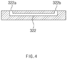
- FIG. 4 is a cross-sectional view illustrating the storage unit of the integrated cartridge, taken along line A-A of FIG. 3 , according to the present invention.
- a pipe may be provided in the storage unit 320.
- An input hole 322a facing the hole 312 defined in the supply unit 310 may be defined in one end of the pipe 322 in a direction of the supply unit 310.
- the fluid containing the effective component may be supplied from the elution part 200 into the pipe 322 through the hole 312 of the supply unit 310 and the input hole 322a of the pipe 322. That is, according to the present invention, the fluid containing the effective component may be supplied into the pipe 322 when the hole 312 defined in the supply unit 310 and the input hole 322a of the pipe 322 match each other.
- FIG. 5 is a perspective view, a plan view, a bottom view, and a side view illustrating the air discharge unit of the integrated cartridge according to the present invention.
- a hole 332 may also be defined in the air discharge unit 330.
- the hole 332 defined in the air discharge unit 330 may provide a path through which air existing inside the pipe 322 of the storage unit 320 is discharged to the outside.
- the hole 332 defined in the air discharge unit 330 may be defined from a top surface of the air discharge unit 330 to a bottom surface to pass through the entire air discharge unit 330 in a thickness direction of the air discharge unit 330.
- an output hole 322b facing the hole 332 defined in the air discharge unit 330 may be defined in the other end of the pipe 322 in a direction of the air discharge unit 330.
- the air existing in the pipe 322 may be discharged to the outside through the air discharge unit 330 when the hole 332 defined in the air discharge unit 330 and the output hole 322b of the pipe 322 match each other.
- the fluid containing the effective component may be supplied into the pipe 322 through the input hole 322a while the air inside the pipe 322 is discharged to the outside through the output hole 322b.
- the pipe 322 of the storage unit 320 may have a very small diameter of 2 mm or less. In this case, it is insufficient to smoothly supply the fluid containing the effective component into the pipe 322 by using only mechanical energy of the fluid containing the effective component.
- the fluid containing the effective component may be transferred in the pipe 322 of the storage unit 320 by capillary force.
- the feature in which 'the fluid containing the effective component is transferred in the pipe by the capillary force' should be interpreted as meaning that main force for transferring the fluid containing the effective component in the pipe 322 is the capillary force and also should not be interpreted as meaning that force for transferring the fluid containing the effective component in the pipe 322 is only the capillary force.
- a coating layer made of a hydrophilic material for generating the capillary force may be disposed on an inner wall of the pipe 322 of the storage unit 320.
- the fluid containing the effective component may be supplied into the pipe 322 by the capillary force that is generated by the coating layer disposed on the inner wall of the pipe 322 and made of the hydrophilic material.
- the fluid containing the effective component may also be transferred in the hole 312 of the supply unit 310 by capillary force.
- a coating layer made of a hydrophilic material for generating the capillary force may be disposed on an inner wall of the hole 312 of the supply unit 310.
- the fluid containing the effective component is not discharged from the pipe 322.
- efficiency in amplification of the effective component during a subsequent amplification operation may be deteriorated. That is, when the fluid containing the effective component is discharged from the pipe 322, an amount of effective component accommodated inside the pipe 322 is reduced by that the amount of discharged effective component, and thus, the effective component may be not sufficiently reproduced during the subsequent amplification operation.
- the fluid containing the effective component is supplied to the pipe 322 through the input hole 322a, it is necessary to prevent the fluid containing the effective component from being discharged through the output hole 322b.
- the coating layer made of the hydrophobic material for suppressing the generation of the capillary force may be disposed on the inner wall of the hole 332 of the air discharge unit 330. Therefore, the efficiency in amplification of the effective component may be enhanced by preventing the fluid containing the effective component supplied into the pipe 322 from being discharged through the output hole 322b.
- one hole 312 may be defined in the supply unit 310 as illustrated in FIG. 2 , and a plurality of pipes 322 may be disposed in the storage unit 320 as illustrated in FIG. 3 (FIG. 3 illustrates a configuration in which four pipes 322 are disposed, and thus, four input holes 322a and four output holes 322b are defined).
- the supply unit 310 may be rotatable. That is, due to the rotation of the supply unit 310, a lower portion of the hole 312 of the supply unit 310 may sequentially match the input holes 322a of the plurality of pipes 322 disposed in the storage unit 320. Also, a protrusion 314 protruding in the form of a cross may be disposed on a lower portion of the supply unit 310 as illustrated in FIG. 2 , and a coupling hole 324 having a penetration shape may be defined in the vicinity of the input holes 322a of the storage unit 320 as illustrated in FIG. 3 . In particular, the plurality of input holes 322a may be defined along a virtual circumference.
- the coupling hole 324 adjacent to the input holes 322a may be defined in a center of a circle constituting the virtual circumference.
- the protrusion 314 of the supply unit 310 may be coupled to the coupling hole 324 adjacent to the input holes 322a.
- the lower portion of the hole 312 of the supply unit 310 may sequentially match the input holes 322a, and as a result, the fluid containing the effective component may be supplied from the hole 312 of the supply unit 310 sequentially to the plurality of pipes 322.
- a plurality of holes 332 may also be defined in the air discharge unit 330 as illustrated in FIG. 5 .
- the air discharge unit 330 may be rotatable.
- a protrusion 314 protruding in the form of a cross may be disposed on a lower portion of the air discharge unit 330 as illustrated in FIG. 5
- a coupling hole 324 having a penetration shape may be defined in the vicinity of the output holes 322b of the storage unit 320 as illustrated in FIG. 3 .
- the plurality of output holes 322b may be defined along a virtual circumference.
- the coupling hole 324 adjacent to the output holes 322b may be defined in a center of a circle constituting the virtual circumference.
- the protrusion 314 of the air discharge unit 330 may be coupled to the coupling hole 324 adjacent to the output holes 322b.
- lower portions of the holes 332 of the air discharge unit 330 may selectively match the output holes 322b.
- the air discharge unit 330 may be controlled according to situations by the rotation of the air discharge unit 330 so that a portion of the holes 332 of the air discharge unit 330 matches a portion of the output holes 322b of the air discharge unit 330, and remaining portions of the holes 332 of the air discharge unit 330 do not match any of the output holes 322b.
- the air inside the pipe 322 may be discharged to the outside when the hole 332 of the air discharge unit 330 matches the output hole 322b of the pipe 322. More preferably, as illustrated in FIGS. 3 and 5 , the number of holes 332 defined in the air discharge unit 330 may be the same as that of output holes 322b defined in the plurality of pipes 322.
- the coating layer made of the hydrophobic material may be disposed on the inner wall of the hole 332 of the air discharge unit 330 to prevent the fluid containing the effective component inside the pipe 322 from being discharged through the output hole 322b.
- a portion of the fluid may pass through the output hole 322b to exist in the hole 332 of the air discharge unit 330.
- the hole 332 of the air discharge unit 330 sequentially matches the plurality of output holes 322b during the rotation of the air discharge unit 330. In this case, cross contamination in which the effective components introduced to each of the pipes 322 is introduced into other pipes 322 may occur.
- the number of holes 332 defined in the air discharge unit 330 may be the same as that of output holes 322b defined in the plurality of pipes 322.
- the holes 332 defined in the air discharge unit 330 may one-to-one correspond to the output holes 322b defined in the plurality of pipes 322 to prevent the cross contamination from occurring.
Landscapes
- Health & Medical Sciences (AREA)
- Chemical & Material Sciences (AREA)
- General Health & Medical Sciences (AREA)
- Analytical Chemistry (AREA)
- Clinical Laboratory Science (AREA)
- Chemical Kinetics & Catalysis (AREA)
- Hematology (AREA)
- Biochemistry (AREA)
- Life Sciences & Earth Sciences (AREA)
- Physics & Mathematics (AREA)
- General Physics & Mathematics (AREA)
- Immunology (AREA)
- Pathology (AREA)
- Molecular Biology (AREA)
- Apparatus Associated With Microorganisms And Enzymes (AREA)
- Automatic Analysis And Handling Materials Therefor (AREA)
- Physical Or Chemical Processes And Apparatus (AREA)
Abstract
Description
- The present application claims the benefit of the priority of
Korean Patent Application No. 10-2018-0121123, filed on October 11, 2018 - The present invention relates to an integrated cartridge, and more specifically, to an integrated cartridge for diagnosing or analyzing a target material.
- A molecular diagnosis is a diagnostic method in which a gene (DNA or RNA) of a target material is directly analyzed to find the infection of disease, base sequence variation, or mutation, thereby enabling early diagnosis of the disease and efficient treatment. In recent, the molecular diagnostic method has been used in various medical fields such as the disease infection confirmation, the genetic testing, and the drug genetics testing.
- Various detection methods have been developed for the molecular diagnostic method and, in particular, realtime polymerase chain reaction is being generally and widely used in recent years because of rapidity, convenience, and sensitivity in detection. A probe that is specifically and complementarily bound to a gene of a detection target material is generally used for the realtime polymerase chain reaction, and a fluorescence molecule is bound to the probe. In the realtime polymerase chain reaction, an analysis instrument is used to analyze a wavelength of the fluorescence molecule, thereby achieving quantitative/qualitative analysis for the target gene.
- Also, in the molecular diagnostic method, the target material is pre-processed through the realtime polymerase chain reaction or the like, and then, the pre-processed material is analyzed. According to the related art, there have been problems in that the molecular diagnostic equipment increases in size and is also complicated in structure due to each of constituents performing various operations required in a molecular diagnostic process.
- Accordingly, an objective of the present invention is to provide a fluid transfer apparatus having a more simplified and compact structure than the structure of the fluid transfer apparatus according to the related art.
- According to one aspect of the present invention in order to achieve the above-described objective, provided is an integrated cartridge including: a pre-processing part configured to pre-process a sample; an elution part configured to elute an effective component from the sample that is pre-processed in the pre-processing part; and an accommodation part configured to accommodate the effective component, wherein the accommodation part includes: a supply unit configured to supply the effective component discharged from the elution part; a storage unit which stores and amplifies the effective component supplied from the supply unit and in which a pipe is provided; and an air discharge unit configured to discharge air existing in the pipe of the storage unit to the outside.
- A hole may be defined in each of the supply unit and the air discharge unit, input and output holes, which face holes defined in the supply unit and the air discharge unit, may be respectively defined in both ends of the pipe provided in the storage unit, and when the hole defined in the supply unit matches the input hole, the effective component may be supplied into the pipe.
- When the effective component is supplied into the pipe, the hole defined in the air discharge unit and the output hole may match each other to discharge the air existing in the pipe to the outside through the air discharge unit.
- The effective component may be transferred in the pipe of the storage unit by capillary force.
- A coating layer made of a hydrophilic material that generates the capillary force may be disposed on an inner wall of the pipe of the storage unit.
- A coating layer made of a hydrophilic material that generates the capillary force may be disposed on an inner wall of the hole of the supply unit.
- A coating layer made of a hydrophobic material that suppresses generation of the capillary force may be disposed on an inner wall of the hole of the air discharge unit.
- One hole may be defined in the supply unit, a plurality of pipes may be disposed in the storage unit, and the supply unit may be provided to be rotatable so as to allow the hole of the supply unit to match the input holes of the plurality of pipes.
- A plurality of holes may defined in the air discharge unit, a plurality of pipes may be disposed in the storage unit, and the air discharge unit may be provided to be rotatable so as to allow the hole of the air discharge unit to match one of the plurality of output holes respectively defined in the plurality of pipes.
- The air discharge unit may have the same number of holes as the output holes defined in the plurality of pipes.
- The accommodation part may be provided below the elution part so that the effective component discharged from the elution part is supplied to the supply unit due to gravity or capillary force.
- According to the present invention, the fluid transfer apparatus may be provided, which has the more simplified and compact structure than the structure of the fluid transfer apparatus according to the related art.
-
-
FIG. 1 is a photograph illustrating an integrated cartridge according to the present invention. -
FIG. 2 is a perspective view, a plan view, a bottom view, and a side view illustrating a supply unit of the integrated cartridge according to the present invention. -
FIG. 3 is a perspective view illustrating a storage unit of the integrated cartridge according to the present invention. -
FIG. 4 is a cross-sectional view illustrating the storage unit of the integrated cartridge, taken along line A-A ofFIG. 3 , according to the present invention. -
FIG. 5 is a perspective view, a plan view, a bottom view, and a side view illustrating an air discharge unit of the integrated cartridge according to the present invention. - Hereinafter, a structure of an integrated cartridge according to the present invention will be described with reference to the accompanying drawings.
-
FIG. 1 is a photograph illustrating an integrated cartridge according to the present invention. - As illustrated in
FIG. 1 , an integratedcartridge 10 according to the present invention may include apre-processing part 100 that pre-processes a sample. The sample that is pre-processed in thepre-processing part 100 may contain a genetic material having nucleic acid. In thepre-processing part 100, a pre-processing operation required prior to eluting the nucleic acid from the sample may be performed as described below. - Also, the integrated
cartridge 10 may include anelution part 200 that elutes an effective component from the sample that is pre-processed in thepre-processing part 100. When the pre-processed sample contains the nucleic acid, theelution part 200 may elute the nucleic acid from the sample. That is, the effective component according to the present invention may be the nucleic acid. However, the effective component according to the present invention is not limited to the nucleic acid. Also, when the effective component is discharged from theelution part 200, water as well as the effective component may be discharged together. Thus, in this specification, the effective component and the water are defined as a 'fluid containing an effective component'. - Also, the integrated
cartridge 10 may further include anaccommodation part 300 that accommodates the fluid containing the effective component eluted from theelution part 200. As described below, the accommodation part may store the fluid containing the effective component, and the effective component stored in the accommodation part may be amplified inside the accommodation part to increase in amount of the effective component. Here, as illustrated inFIG. 1 , theaccommodation part 300 may be provided below theelution part 200. In this case, the fluid containing the effective component discharged from theelution part 200 may fall down vertically due to the gravity or capillary force as described below so as to be naturally supplied to theaccommodation part 300. - Referring to
FIG. 1 again, theaccommodation part 300 may include asupply unit 310 that supplies the fluid containing the effective component discharged from theelution part 200. In particular, thesupply unit 310 may be provided below theelution part 200. Thus, the fluid containing the effective component discharged from theelution part 200 may fall down vertically due to the gravity or capillary force as described below so as to be supplied to thesupply unit 310. - Also, the
accommodation part 300 may include astorage unit 320 that stores and amplifies the fluid containing the effective component supplied from thesupply unit 310 and may further include anair discharge unit 330 that discharges air existing inside thestorage unit 320 to the outside. Hereinafter, a structure of each of thesupply unit 310, thestorage unit 320, and theair discharge unit 330 will be described in more detail. -
FIG. 2 is a perspective view, a plan view, a bottom view, and a side view illustrating the supply unit of the integrated cartridge according to the present invention. - As illustrated in
FIG. 2 , ahole 312 may be defined in thesupply unit 310. Thehole 312 defined in thesupply unit 310 may provide a path through which the fluid containing the effective component discharged from theelution part 200 moves. As illustrated inFIG. 2 , thehole 312 defined in thesupply unit 310 may be defined from a top surface of thesupply unit 310 to a bottom surface to pass through theentire supply unit 310 in a thickness direction of thesupply unit 310. -
FIG. 3 is a perspective view illustrating the storage unit of the integrated cartridge according to the present invention, andFIG. 4 is a cross-sectional view illustrating the storage unit of the integrated cartridge, taken along line A-A ofFIG. 3 , according to the present invention. - As illustrated
FIGS. 3 and4 , a pipe may be provided in thestorage unit 320. Aninput hole 322a facing thehole 312 defined in thesupply unit 310 may be defined in one end of thepipe 322 in a direction of thesupply unit 310. The fluid containing the effective component may be supplied from theelution part 200 into thepipe 322 through thehole 312 of thesupply unit 310 and theinput hole 322a of thepipe 322. That is, according to the present invention, the fluid containing the effective component may be supplied into thepipe 322 when thehole 312 defined in thesupply unit 310 and theinput hole 322a of thepipe 322 match each other. -
FIG. 5 is a perspective view, a plan view, a bottom view, and a side view illustrating the air discharge unit of the integrated cartridge according to the present invention. - As illustrated in
FIG. 5 , ahole 332 may also be defined in theair discharge unit 330. Thehole 332 defined in theair discharge unit 330 may provide a path through which air existing inside thepipe 322 of thestorage unit 320 is discharged to the outside. As illustrated inFIG. 4 , thehole 332 defined in theair discharge unit 330 may be defined from a top surface of theair discharge unit 330 to a bottom surface to pass through the entireair discharge unit 330 in a thickness direction of theair discharge unit 330. - Also, as illustrated in
FIGS. 3 and4 , anoutput hole 322b facing thehole 332 defined in theair discharge unit 330 may be defined in the other end of thepipe 322 in a direction of theair discharge unit 330. Thus, according to the present invention, the air existing in thepipe 322 may be discharged to the outside through theair discharge unit 330 when thehole 332 defined in theair discharge unit 330 and theoutput hole 322b of thepipe 322 match each other. In particular, when theinput hole 322a of thepipe 322 matches thehole 312 of thesupply unit 310, and simultaneously, theoutput hole 322b of thepipe 322 matches thehole 332 of theair discharge unit 330, the fluid containing the effective component may be supplied into thepipe 322 through theinput hole 322a while the air inside thepipe 322 is discharged to the outside through theoutput hole 322b. - Also, the
pipe 322 of thestorage unit 320 according to the present invention may have a very small diameter of 2 mm or less. In this case, it is insufficient to smoothly supply the fluid containing the effective component into thepipe 322 by using only mechanical energy of the fluid containing the effective component. Thus, according to the present invention, the fluid containing the effective component may be transferred in thepipe 322 of thestorage unit 320 by capillary force. The feature in which 'the fluid containing the effective component is transferred in the pipe by the capillary force' should be interpreted as meaning that main force for transferring the fluid containing the effective component in thepipe 322 is the capillary force and also should not be interpreted as meaning that force for transferring the fluid containing the effective component in thepipe 322 is only the capillary force. - In order that the fluid containing the effective component is transferred in the
pipe 322 by the capillary force, a coating layer made of a hydrophilic material for generating the capillary force may be disposed on an inner wall of thepipe 322 of thestorage unit 320. Thus, the fluid containing the effective component may be supplied into thepipe 322 by the capillary force that is generated by the coating layer disposed on the inner wall of thepipe 322 and made of the hydrophilic material. - Similar to the
pipe 322, the fluid containing the effective component may also be transferred in thehole 312 of thesupply unit 310 by capillary force. For this, a coating layer made of a hydrophilic material for generating the capillary force may be disposed on an inner wall of thehole 312 of thesupply unit 310. - Also, it is preferable that, after the fluid containing the effective component is transferred into the
pipe 322, the fluid containing the effective component is not discharged from thepipe 322. This is done because, when the fluid containing the effective component is discharged from thepipe 322, efficiency in amplification of the effective component during a subsequent amplification operation may be deteriorated. That is, when the fluid containing the effective component is discharged from thepipe 322, an amount of effective component accommodated inside thepipe 322 is reduced by that the amount of discharged effective component, and thus, the effective component may be not sufficiently reproduced during the subsequent amplification operation. Thus, when the fluid containing the effective component is supplied to thepipe 322 through theinput hole 322a, it is necessary to prevent the fluid containing the effective component from being discharged through theoutput hole 322b. - For this, the coating layer made of the hydrophobic material for suppressing the generation of the capillary force may be disposed on the inner wall of the
hole 332 of theair discharge unit 330. Therefore, the efficiency in amplification of the effective component may be enhanced by preventing the fluid containing the effective component supplied into thepipe 322 from being discharged through theoutput hole 322b. - Also, one
hole 312 may be defined in thesupply unit 310 as illustrated inFIG. 2 , and a plurality ofpipes 322 may be disposed in thestorage unit 320 as illustrated inFIG. 3 (FIG. 3 illustrates a configuration in which fourpipes 322 are disposed, and thus, fourinput holes 322a and fouroutput holes 322b are defined). - Here, the
supply unit 310 may be rotatable. That is, due to the rotation of thesupply unit 310, a lower portion of thehole 312 of thesupply unit 310 may sequentially match the input holes 322a of the plurality ofpipes 322 disposed in thestorage unit 320. Also, aprotrusion 314 protruding in the form of a cross may be disposed on a lower portion of thesupply unit 310 as illustrated inFIG. 2 , and acoupling hole 324 having a penetration shape may be defined in the vicinity of the input holes 322a of thestorage unit 320 as illustrated inFIG. 3 . In particular, the plurality ofinput holes 322a may be defined along a virtual circumference. In this case, thecoupling hole 324 adjacent to theinput holes 322a may be defined in a center of a circle constituting the virtual circumference. Theprotrusion 314 of thesupply unit 310 may be coupled to thecoupling hole 324 adjacent to theinput holes 322a. Thus, according to the present invention, as theprotrusion 314 coupled to thecoupling hole 324 adjacent to theinput holes 322a rotates, the lower portion of thehole 312 of thesupply unit 310 may sequentially match theinput holes 322a, and as a result, the fluid containing the effective component may be supplied from thehole 312 of thesupply unit 310 sequentially to the plurality ofpipes 322. - On the other hand, when the plurality of
pipes 322 are disposed in thestorage unit 320, a plurality ofholes 332 may also be defined in theair discharge unit 330 as illustrated inFIG. 5 . In addition, theair discharge unit 330 may be rotatable. Furthermore, aprotrusion 314 protruding in the form of a cross may be disposed on a lower portion of theair discharge unit 330 as illustrated inFIG. 5 , and acoupling hole 324 having a penetration shape may be defined in the vicinity of the output holes 322b of thestorage unit 320 as illustrated inFIG. 3 . In particular, the plurality ofoutput holes 322b may be defined along a virtual circumference. In this case, thecoupling hole 324 adjacent to theoutput holes 322b may be defined in a center of a circle constituting the virtual circumference. Theprotrusion 314 of theair discharge unit 330 may be coupled to thecoupling hole 324 adjacent to the output holes 322b. Thus, as theprotrusion 314 coupled to thecoupling hole 324 adjacent to theoutput holes 322b rotates, lower portions of theholes 332 of theair discharge unit 330 may selectively match the output holes 322b. As a result, it may be controlled according to situations by the rotation of theair discharge unit 330 so that a portion of theholes 332 of theair discharge unit 330 matches a portion of the output holes 322b of theair discharge unit 330, and remaining portions of theholes 332 of theair discharge unit 330 do not match any of the output holes 322b. - It has been described above that the air inside the
pipe 322 may be discharged to the outside when thehole 332 of theair discharge unit 330 matches theoutput hole 322b of thepipe 322. More preferably, as illustrated inFIGS. 3 and5 , the number ofholes 332 defined in theair discharge unit 330 may be the same as that ofoutput holes 322b defined in the plurality ofpipes 322. - As described above, the coating layer made of the hydrophobic material may be disposed on the inner wall of the
hole 332 of theair discharge unit 330 to prevent the fluid containing the effective component inside thepipe 322 from being discharged through theoutput hole 322b. However, in spite of preventing the fluid containing the effective component from being discharged through theoutput hole 322b, a portion of the fluid may pass through theoutput hole 322b to exist in thehole 332 of theair discharge unit 330. Here, if only onehole 332 is provided in theair discharge unit 330, thehole 332 of theair discharge unit 330 sequentially matches the plurality ofoutput holes 322b during the rotation of theair discharge unit 330. In this case, cross contamination in which the effective components introduced to each of thepipes 322 is introduced intoother pipes 322 may occur. - To solve the problem such as the cross contamination, the number of
holes 332 defined in theair discharge unit 330 may be the same as that ofoutput holes 322b defined in the plurality ofpipes 322. In this case, theholes 332 defined in theair discharge unit 330 may one-to-one correspond to the output holes 322b defined in the plurality ofpipes 322 to prevent the cross contamination from occurring. - Although the present invention is described by specific embodiments and drawings as described above, the present invention is not limited thereto and it is obvious that various changes and modifications may be made by those having ordinary skill in the art within the technical idea of the present invention and equivalent scope of the appended claims.
Claims (11)
- An integrated cartridge comprising:a pre-processing part configured to pre-process a sample;an elution part configured to elute an effective component from the sample that is pre-processed in the pre-processing part; andan accommodation part configured to accommodate the effective component,wherein the accommodation part comprises:a supply unit configured to supply the effective component discharged from the elution part;a storage unit which stores and amplifies the effective component supplied from the supply unit and in which a pipe is provided; andan air discharge unit configured to discharge air existing in the pipe of the storage unit to the outside.
- The integrated cartridge of claim 1, wherein a hole is defined in each of the supply unit and the air discharge unit,
input and output holes, which face holes defined in the supply unit and the air discharge unit, are respectively defined in both ends of the pipe provided in the storage unit, and
when the hole defined in the supply unit matches the input hole, the effective component is supplied into the pipe. - The integrated cartridge of claim 2, wherein when the effective component is supplied into the pipe, the hole defined in the air discharge unit and the output hole match each other to discharge the air existing in the pipe to the outside through the air discharge unit.
- The integrated cartridge of claim 2, wherein the effective component is transferred in the pipe of the storage unit by capillary force.
- The integrated cartridge of claim 4, wherein a coating layer made of a hydrophilic material that generates the capillary force is disposed on an inner wall of the pipe of the storage unit.
- The integrated cartridge of claim 4, wherein a coating layer made of a hydrophilic material that generates the capillary force is disposed on an inner wall of the hole of the supply unit.
- The integrated cartridge of claim 4, wherein a coating layer made of a hydrophobic material that suppresses generation of the capillary force is disposed on an inner wall of the hole of the air discharge unit.
- The integrated cartridge of claim 2, wherein one hole is defined in the supply unit,
a plurality of pipes are disposed in the storage unit, and
the supply unit is provided to be rotatable so as to allow the hole of the supply unit to match the input holes of the plurality of pipes. - The integrated cartridge of claim 2, wherein a plurality of holes are defined in the air discharge unit,
a plurality of pipes are disposed in the storage unit, and
the air discharge unit is provided to be rotatable so as to allow the hole of the air discharge unit to match one of the plurality of output holes respectively defined in the plurality of pipes. - The integrated cartridge of claim 9, wherein the air discharge unit has the same number of holes as the output holes defined in the plurality of pipes.
- The integrated cartridge of claim 1, wherein the accommodation part is provided below the elution part so that the effective component discharged from the elution part is supplied to the supply unit due to gravity or capillary force.
Applications Claiming Priority (2)
| Application Number | Priority Date | Filing Date | Title |
|---|---|---|---|
| KR1020180121123A KR101996617B1 (en) | 2018-10-11 | 2018-10-11 | Integrated cartridge |
| PCT/KR2019/009868 WO2020075963A1 (en) | 2018-10-11 | 2019-08-07 | Integrated cartridge |
Publications (2)
| Publication Number | Publication Date |
|---|---|
| EP3838406A1 true EP3838406A1 (en) | 2021-06-23 |
| EP3838406A4 EP3838406A4 (en) | 2021-11-03 |
Family
ID=67259433
Family Applications (1)
| Application Number | Title | Priority Date | Filing Date |
|---|---|---|---|
| EP19871367.9A Pending EP3838406A4 (en) | 2018-10-11 | 2019-08-07 | Integrated cartridge |
Country Status (7)
| Country | Link |
|---|---|
| US (1) | US20220032284A1 (en) |
| EP (1) | EP3838406A4 (en) |
| JP (1) | JP7191440B2 (en) |
| KR (1) | KR101996617B1 (en) |
| CN (1) | CN112703058B (en) |
| TW (1) | TWI718621B (en) |
| WO (1) | WO2020075963A1 (en) |
Families Citing this family (1)
| Publication number | Priority date | Publication date | Assignee | Title |
|---|---|---|---|---|
| KR101996617B1 (en) * | 2018-10-11 | 2019-07-04 | 주식회사 엘지화학 | Integrated cartridge |
Family Cites Families (28)
| Publication number | Priority date | Publication date | Assignee | Title |
|---|---|---|---|---|
| DE4420732A1 (en) * | 1994-06-15 | 1995-12-21 | Boehringer Mannheim Gmbh | Device for the treatment of nucleic acids from a sample |
| CN100483124C (en) * | 2002-10-04 | 2009-04-29 | 普罗托赛拉株式会社 | Plate for mass spectrometry, process for preparing the same and use thereof |
| EP1885839B1 (en) * | 2005-04-26 | 2018-08-08 | Life Technologies Corporation | Systems and methods for multiple analyte detection |
| WO2007053186A2 (en) * | 2005-05-31 | 2007-05-10 | Labnow, Inc. | Methods and compositions related to determination and use of white blood cell counts |
| EP1946830B1 (en) * | 2005-11-07 | 2019-04-03 | Konica Minolta Medical & Graphic, Inc. | Microreactor |
| JP2007333706A (en) * | 2006-06-19 | 2007-12-27 | Sekisui Chem Co Ltd | Cartridge type detection device |
| JP5523327B2 (en) * | 2007-10-12 | 2014-06-18 | レオニックス,インコーポレイテッド | Integrated microfluidic device and method |
| US7759112B2 (en) * | 2007-10-31 | 2010-07-20 | Akonni Biosystems, Inc. | Apparatus, system, and method for purifying nucleic acids |
| JP4453090B2 (en) * | 2007-11-08 | 2010-04-21 | セイコーエプソン株式会社 | Biological sample reaction chip and biological sample reaction method |
| KR101226957B1 (en) | 2008-12-08 | 2013-02-07 | 한국전자통신연구원 | Disposable diagnostic kit |
| JP5706442B2 (en) * | 2009-12-24 | 2015-04-22 | エルジー イノテック カンパニー リミテッド | Heat treatment container for vacuum heat treatment equipment |
| WO2011096782A2 (en) * | 2010-02-08 | 2011-08-11 | Seo Yu-Jin | Liquid flow apparatus, fixed quantity liquid supply apparatus, and target substance extracting apparatus and target substance extracting method using the two apparatuses |
| AU2011220873B2 (en) * | 2010-02-23 | 2014-07-10 | Luminex Corporation | Apparatus and methods for integrated sample preparation, reaction and detection |
| US9180451B2 (en) * | 2010-06-28 | 2015-11-10 | Stmicroelectronics S.R.L. | Fluidic cartridge for detecting chemicals in samples, in particular for performing biochemical analyses |
| BR112013022735A2 (en) * | 2011-03-09 | 2016-12-06 | 3M Innovative Properties Co | apparatus for processing a sample, apparatus for processing a plurality of samples, method for detecting the presence or absence of an analyte in a sample and method for detecting the presence or absence of an analyte in a plurality of samples |
| US9469871B2 (en) * | 2011-04-14 | 2016-10-18 | Corporos Inc. | Methods and apparatus for point-of-care nucleic acid amplification and detection |
| KR101407655B1 (en) | 2012-10-11 | 2014-06-13 | 주식회사 인포피아 | Sample processing apparatus and automatic analyzing apparatus including the same |
| US9211512B2 (en) * | 2012-11-28 | 2015-12-15 | Samsung Electronics Co., Ltd. | Microfluidic apparatus and method of enriching target cells by using the same |
| US20150167052A1 (en) * | 2013-12-13 | 2015-06-18 | General Electric Company | Sample storage and extraction device for flow through elution of analytes |
| WO2016093332A1 (en) | 2014-12-12 | 2016-06-16 | パナソニックヘルスケアホールディングス株式会社 | Substrate for sample analysis, sample analysis device, sample analysis system, and program for sample analysis system |
| ES2898103T3 (en) * | 2014-12-31 | 2022-03-03 | Visby Medical Inc | Devices for molecular diagnostic tests |
| WO2016117726A1 (en) * | 2015-01-23 | 2016-07-28 | Infopia Co., Ltd. | Cartridge |
| US10300486B2 (en) * | 2015-07-17 | 2019-05-28 | Stat-Diagnostica & Innovation, S.L. | Dry chemistry container |
| JP2018533490A (en) * | 2015-07-21 | 2018-11-15 | ディエヌピー123・カンパニーDNP123 Company | Programmable self-assembled patch nanoparticles and associated devices, systems and methods |
| KR20230156168A (en) * | 2015-08-08 | 2023-11-13 | 스토베 게엠베하 | Disposable bioprocess system supporting biological activity |
| CN105316224B (en) * | 2015-12-07 | 2017-10-27 | 中国科学院苏州生物医学工程技术研究所 | Full-automatic nucleic acid extraction expands micro-fluidic chip and its application process with PCR |
| CN109863396B (en) | 2016-10-05 | 2021-11-05 | 雅培实验室 | Apparatus and method for sample analysis |
| KR101996617B1 (en) * | 2018-10-11 | 2019-07-04 | 주식회사 엘지화학 | Integrated cartridge |
-
2018
- 2018-10-11 KR KR1020180121123A patent/KR101996617B1/en active Active
-
2019
- 2019-08-07 WO PCT/KR2019/009868 patent/WO2020075963A1/en not_active Ceased
- 2019-08-07 CN CN201980060006.9A patent/CN112703058B/en active Active
- 2019-08-07 EP EP19871367.9A patent/EP3838406A4/en active Pending
- 2019-08-07 JP JP2021517775A patent/JP7191440B2/en active Active
- 2019-08-07 US US17/278,846 patent/US20220032284A1/en not_active Abandoned
- 2019-08-14 TW TW108128884A patent/TWI718621B/en active
Also Published As
| Publication number | Publication date |
|---|---|
| EP3838406A4 (en) | 2021-11-03 |
| CN112703058B (en) | 2022-10-25 |
| TWI718621B (en) | 2021-02-11 |
| WO2020075963A1 (en) | 2020-04-16 |
| TW202014523A (en) | 2020-04-16 |
| JP7191440B2 (en) | 2022-12-19 |
| JP2022503948A (en) | 2022-01-12 |
| US20220032284A1 (en) | 2022-02-03 |
| CN112703058A (en) | 2021-04-23 |
| KR101996617B1 (en) | 2019-07-04 |
Similar Documents
| Publication | Publication Date | Title |
|---|---|---|
| RU2699612C2 (en) | Sample cassette and analytical system for carrying out certain reactions | |
| AU2009201529B2 (en) | Apparatus For Polynucleotide Detection and Quantitation | |
| CN109416331B (en) | Reagent mixing system and method | |
| KR102043320B1 (en) | Fluidic system for reagent delivery to a flow cell | |
| CN106443039B (en) | System and method for transfer liquid sample | |
| US12320734B2 (en) | Reagent nozzle sipper mixing system and method | |
| CN110945363B (en) | A module for transferring magnetic beads, an automated system including the module, and a method for extracting nucleic acid using the module | |
| JP2005530504A (en) | Title of invention: Manual set for construction of tissue microarray | |
| CN107083319A (en) | Testing cassete with integrated delivery module | |
| EA004719B1 (en) | Device for thermo-dependent chain amplification of target nucleic acid sequences | |
| EP3838406A1 (en) | Integrated cartridge | |
| JP2007534936A (en) | A device to analyze the interaction between target and probe molecules | |
| KR102281116B1 (en) | integrated cartridge | |
| TWI390201B (en) | Fluid manipulation gene array analysis wafers | |
| KR102458032B1 (en) | Rt-pcr device | |
| CN206140534U (en) | Stub bar is got to biological sample test tube | |
| HK40003106B (en) | Reagent nozzle sipper mixing system and method | |
| HK40003106A (en) | Reagent nozzle sipper mixing system and method |
Legal Events
| Date | Code | Title | Description |
|---|---|---|---|
| STAA | Information on the status of an ep patent application or granted ep patent |
Free format text: STATUS: THE INTERNATIONAL PUBLICATION HAS BEEN MADE |
|
| PUAI | Public reference made under article 153(3) epc to a published international application that has entered the european phase |
Free format text: ORIGINAL CODE: 0009012 |
|
| STAA | Information on the status of an ep patent application or granted ep patent |
Free format text: STATUS: REQUEST FOR EXAMINATION WAS MADE |
|
| 17P | Request for examination filed |
Effective date: 20210318 |
|
| AK | Designated contracting states |
Kind code of ref document: A1 Designated state(s): AL AT BE BG CH CY CZ DE DK EE ES FI FR GB GR HR HU IE IS IT LI LT LU LV MC MK MT NL NO PL PT RO RS SE SI SK SM TR |
|
| A4 | Supplementary search report drawn up and despatched |
Effective date: 20211005 |
|
| RIC1 | Information provided on ipc code assigned before grant |
Ipc: B01L 7/00 20060101ALI20210929BHEP Ipc: G01N 35/00 20060101ALI20210929BHEP Ipc: B01L 3/00 20060101AFI20210929BHEP |
|
| DAV | Request for validation of the european patent (deleted) | ||
| DAX | Request for extension of the european patent (deleted) | ||
| RAP1 | Party data changed (applicant data changed or rights of an application transferred) |
Owner name: INVITROS CO., LTD. |