EP3838361A1 - Cards, card reading system, and card set - Google Patents
Cards, card reading system, and card set Download PDFInfo
- Publication number
- EP3838361A1 EP3838361A1 EP19849490.8A EP19849490A EP3838361A1 EP 3838361 A1 EP3838361 A1 EP 3838361A1 EP 19849490 A EP19849490 A EP 19849490A EP 3838361 A1 EP3838361 A1 EP 3838361A1
- Authority
- EP
- European Patent Office
- Prior art keywords
- card
- end part
- cards
- reference line
- adjacent
- Prior art date
- Legal status (The legal status is an assumption and is not a legal conclusion. Google has not performed a legal analysis and makes no representation as to the accuracy of the status listed.)
- Granted
Links
Images






Classifications
-
- A—HUMAN NECESSITIES
- A63—SPORTS; GAMES; AMUSEMENTS
- A63H—TOYS, e.g. TOPS, DOLLS, HOOPS OR BUILDING BLOCKS
- A63H17/00—Toy vehicles, e.g. with self-drive; ; Cranes, winches or the like; Accessories therefor
- A63H17/26—Details; Accessories
- A63H17/36—Steering-mechanisms for toy vehicles
- A63H17/395—Steering-mechanisms for toy vehicles steered by program
-
- A—HUMAN NECESSITIES
- A63—SPORTS; GAMES; AMUSEMENTS
- A63F—CARD, BOARD, OR ROULETTE GAMES; INDOOR GAMES USING SMALL MOVING PLAYING BODIES; VIDEO GAMES; GAMES NOT OTHERWISE PROVIDED FOR
- A63F1/00—Card games
- A63F1/02—Cards; Special shapes of cards
-
- A—HUMAN NECESSITIES
- A63—SPORTS; GAMES; AMUSEMENTS
- A63H—TOYS, e.g. TOPS, DOLLS, HOOPS OR BUILDING BLOCKS
- A63H18/00—Highways or trackways for toys; Propulsion by special interaction between vehicle and track
- A63H18/02—Construction or arrangement of the trackway
-
- A—HUMAN NECESSITIES
- A63—SPORTS; GAMES; AMUSEMENTS
- A63H—TOYS, e.g. TOPS, DOLLS, HOOPS OR BUILDING BLOCKS
- A63H18/00—Highways or trackways for toys; Propulsion by special interaction between vehicle and track
- A63H18/16—Control of vehicle drives by interaction between vehicle and track; Control of track elements by vehicles
-
- A—HUMAN NECESSITIES
- A63—SPORTS; GAMES; AMUSEMENTS
- A63H—TOYS, e.g. TOPS, DOLLS, HOOPS OR BUILDING BLOCKS
- A63H30/00—Remote-control arrangements specially adapted for toys, e.g. for toy vehicles
- A63H30/02—Electrical arrangements
- A63H30/04—Electrical arrangements using wireless transmission
-
- A—HUMAN NECESSITIES
- A63—SPORTS; GAMES; AMUSEMENTS
- A63H—TOYS, e.g. TOPS, DOLLS, HOOPS OR BUILDING BLOCKS
- A63H33/00—Other toys
- A63H33/26—Magnetic or electric toys
-
- G—PHYSICS
- G09—EDUCATION; CRYPTOGRAPHY; DISPLAY; ADVERTISING; SEALS
- G09B—EDUCATIONAL OR DEMONSTRATION APPLIANCES; APPLIANCES FOR TEACHING, OR COMMUNICATING WITH, THE BLIND, DEAF OR MUTE; MODELS; PLANETARIA; GLOBES; MAPS; DIAGRAMS
- G09B19/00—Teaching not covered by other main groups of this subclass
- G09B19/0053—Computers, e.g. programming
-
- A—HUMAN NECESSITIES
- A63—SPORTS; GAMES; AMUSEMENTS
- A63H—TOYS, e.g. TOPS, DOLLS, HOOPS OR BUILDING BLOCKS
- A63H2200/00—Computerized interactive toys, e.g. dolls
Definitions
- the present invention relates to a card, a card reading system, and a card set.
- An object of the invention is therefore to provide technology for reading cards more reliably than before.
- FIG. 4 is a view depicting an example of the sheet 31 on which the carriage 20 is placed.
- FIG. 4 gives the example in which multiple sheets 31 are provided in book form. Each of the sheets 31 is printed with an image visible to the user and with a pattern that can be captured by the camera 24.
- a maze formed by 5 ⁇ 5 squares constitutes the image visible to the user.
- the maze is arranged for programming study purposes.
- the user creates a simplified hands-on practice program, with the carriage 20 made to move from a start square 33a of the maze in accordance with the created hands-on practice program.
- the control system controls the carriage 20 in a manner not traveling over an impassable square 33i.
- the device control apparatus 10 outputs a sound signifying that the user has successfully created the practice program.
- FIG. 9 is a view depicting an example of assigning command cards 40 with respect to a coordinate space.
- FIG. 9 illustrates images of the command cards 40 for the purpose of simplified explanation
- the information indicating the assignment of the command cards 40 relative to the coordinate space need only associate the regions with the types (commands) of the command cards 40.
- the shapes of the actual command cards 40 need not be stored as the information indicative of their assignment.
- the information indicating assignment may be information that associates a rectangular region enclosing a command card 40 with the type of that command card 40 indicated by that region.
- the broken lines in FIG. 9 denote the reference line 45 corresponding to each of the command cards 40.
- the y coordinate of the reference line 45 varies depending on the command card 40.
- all command cards 40 may be arrayed in the y direction in a straight line centering on the reference line 45. In this case, the y coordinate of the reference line 45 remains unchanged. As can be seen in FIG. 9 , the coordinates assigned to each command card 40 in the coordinate space indicate its positional relation relative to the reference line 45.
Landscapes
- Engineering & Computer Science (AREA)
- Business, Economics & Management (AREA)
- Computer Hardware Design (AREA)
- Entrepreneurship & Innovation (AREA)
- Physics & Mathematics (AREA)
- Educational Administration (AREA)
- Educational Technology (AREA)
- General Physics & Mathematics (AREA)
- Theoretical Computer Science (AREA)
- Multimedia (AREA)
- Computer Networks & Wireless Communication (AREA)
- Toys (AREA)
Abstract
Description
- The present invention relates to a card, a card reading system, and a card set.
- Study materials for intuitive programming, for example, are marketed extensively, the materials being cards that are arrayed for programming purposes. Also, study materials that involve the use of cards physically made of paper have been publicized. A user using these materials arrays multiple cards to create a sequence of cards. On each of the multiple cards, a command is written, for example. A camera-equipped self-propelled device is allowed to travel over the card sequence to read information such as commands from the cards.
- PTL 1 discloses arrangements in which a user arrays tiles to form a command sequence. A self-propelled device is then placed at one end of the command sequence and allowed to move over the field of command sequences. The self-propelled device reads commands recorded on the individual tiles and, on the basis of the read commands, controls another self-propelled device in movement.
-
- For example, users not skillful with their fingers such as young children have difficulty arraying cards neatly. Meanwhile, depending on how multiple cards are arrayed, the self-propelled device may deviate from the card sequence during reading and may fail to read the subsequent cards.
- The present invention has been made in view of the above circumstances. An object of the invention is therefore to provide technology for reading cards more reliably than before.
- In solving the above problem and according to the present invention, there is provided a card including a first end part configured to be adjacent to another card in a predetermined direction; a second end part configured to be on the opposite side of the first end part and adjacent to another card different from the first end part; and a surface printed with a pattern in which are coded coordinates indicating a positional relation relative to a reference line extended in the predetermined direction indicative of a region in which a self-propelled device is to travel. Each of the first and the second end parts has a positioning part regulating how the other card adjacent to the end part is to be placed. The positioning parts and the reference line have a predetermined positional relation therebetween.
- Also according to the present invention, there is provided a card reading system including current position acquisition means configured to acquire the current position of a self-propelled device by recognizing a pattern printed on a card having a first end part and a second end part, the first end part having a positioning part regulating how another card adjacent to the first end part in a predetermined direction is to be placed, the second end part having a positioning part located on the opposite side of the first end part to regulate how another card adjacent to the second end part is to be placed, the pattern being one in which are coded coordinates indicating a positional relation relative to a reference line extended in the predetermined direction; and a travel control section configured to control the self-propelled device to travel on the basis of the acquired current position and the reference line.
- Also according to the present invention, there is provided a card set including multiple cards configured to be arrayed in a predetermined direction, each of the cards including a first end part configured to be adjacent to another card; a second end part configured to be on the opposite side of the first end part and adjacent to another card different from the first end part; and a surface printed with a pattern in which are coded coordinates indicating a positional relation relative to a reference line extended in the predetermined direction indicative of a region in which a self-propelled device is to travel. Each of the first and the second end parts has a positioning part regulating how the other card adjacent to the end part is to be placed. The positioning parts and the reference line have a predetermined positional relation therebetween.
- Thus, according to the present invention, a self-propelled reading device is enabled to read cards more reliably than before.
- In a preferred embodiment of the present invention, the positioning part belonging to one of the first and the second end parts may have a recessed portion and the positioning part belonging to the other end part may have a projected portion in planar view.
- In another preferred embodiment of the present invention, the surface may be printed with a line extended in the predetermined direction to constitute the positioning parts.
- Another preferred embodiment of the present invention may further include an opening configured to intersect with the reference line in planar view. An additional card printed with a pattern in which are coded the coordinates indicating the positional relation relative to the reference line may be fitted into the opening.
-
- [
FIG. 1 ]
FIG. 1 is a view depicting an example of a control system as an embodiment of the present invention. - [
FIG. 2 ]
FIG. 2 is a view depicting a hardware configuration of the control system. - [
FIG. 3 ]
FIG. 3 is a view depicting an example of a carriage. - [
FIG. 4 ]
FIG. 4 is a view depicting an example of sheets on which the carriage is placed. - [
FIG. 5 ]
FIG. 5 is a view depicting an example of multiple command cards being arrayed. - [
FIG. 6 ]
FIG. 6 is a plan view explaining the shape of a command card. - [
FIG. 7 ]
FIG. 7 is a block diagram depicting functions implemented by the control system. - [
FIG. 8 ]
FIG. 8 is a flowchart depicting a typical process of reading command cards. - [
FIG. 9 ]
FIG. 9 is a view depicting an example of assigning command cards with respect to a coordinate space. - [
FIG. 10 ]
FIG. 10 is a view explaining a method of controlling the carriage. - [
FIG. 11 ]
FIG. 11 is a view depicting an example of course cards being arrayed. - [
FIG. 12 ]
FIG. 12 is a view depicting an example of assigning the course cards with respect to a coordinate space. - One embodiment of the present invention is described below with reference to the accompanying drawings. Of the constituent elements that appear in this description, those having the same functions will be designated by the same reference signs, and their explanations will be omitted where redundant. A control system embodying the present invention is explained below as a programming study material in which cards printed with command names are arrayed in a predetermined direction to create a program for hands-on practice (referred to as the "hands-on practice program" hereunder) and the arrayed cards are read by a self-propelled device. With this programming study material, the self-propelled device travels through a maze in accordance with the read program.
-
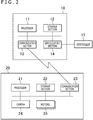
FIG. 1 is a view depicting an example of the control system as one embodiment of the present invention.FIG. 2 is a view depicting a hardware configuration example of the control system embodying the present invention. The control system of the present invention includes adevice control apparatus 10,carriages controller 17, and acartridge 18. Thecarriages camera 24 and have the same functions. In the description that follows, thecarriages carriage 20 where there is no specific need to distinguish the two carriages. Thedevice control apparatus 10 controls thecarriage 20 wirelessly. Thecontroller 17 is an input apparatus that acquires operations performed by the user and is connected by cable to thedevice control apparatus 10.FIG. 3 is a view depicting an example of thecarriage 20.FIG. 3 illustrates thecarriage 20 as viewed from below. Thecarriage 20 further includes apower switch 250, aswitch 222, and twowheels 254. - The
device control apparatus 10 includes aprocessor 11, astorage section 12, acommunication section 13, and an input/output section 14. Thecarriage 20 includes aprocessor 21, astorage section 22, acommunication section 23, acamera 24, and twomotors 25. Thedevice control apparatus 10 may be either a dedicated apparatus for control purposes or a general-purpose computer. - The
processor 11 controls thecommunication section 13 and the input/output section 14 by working in accordance with programs stored in thestorage section 12. Theprocessor 21 controls thecommunication section 23, thecamera 24, and themotors 25 by working in accordance with programs stored in thestorage section 22. These programs are provided by being stored on computer-readable storage media such as a flash memory in thecartridge 18. The programs may alternatively be provided via networks such as the Internet. - The
storage section 12 includes a dynamic random access memory (DRAM) and a flash memory incorporated in thedevice control apparatus 10 and the flash memory in thecartridge 18. Thestorage section 22 includes a DRAM and a flash memory. Thestorage sections storage sections processors communication sections - The
communication sections communication sections processors communication sections processors storage sections communication section 13 may have a function of communicating with other apparatuses via networks such as a local area network (LAN). - The input/
output section 14 includes circuits for acquiring information from input devices such as thecontroller 17 and circuits for controlling output devices such as a sound output device and an image display device. The input/output section 14 acquires an input signal from the input device, converts the input signal into information, and inputs the information to theprocessor 11 and to thestorage section 12. Also, under control of theprocessor 11, the input/output section 14 causes speakers to output sounds and the display device to output images. - The
motors 25 are what are generally called servo motors of which the rotating direction, the amount of rotation, and the rotational speed are controlled by theprocessor 21. The twomotors 25 are each assigned onewheel 254, and eachmotor 25 drives the assignedwheel 254. - The
camera 24 arranged to image the lower side of thecarriage 20 captures patterns printed on a sheet 31 (seeFIG. 4 ) on which thecarriage 20 is placed. With this embodiment, thesheets 31 are printed with patterns recognizable in the infrared frequency domain. Thecamera 24 captures such infrared-sensitive images on the sheets. -
FIG. 4 is a view depicting an example of thesheet 31 on which thecarriage 20 is placed.FIG. 4 gives the example in whichmultiple sheets 31 are provided in book form. Each of thesheets 31 is printed with an image visible to the user and with a pattern that can be captured by thecamera 24. In the example ofFIG. 4 , a maze formed by 5 × 5 squares constitutes the image visible to the user. The maze is arranged for programming study purposes. The user creates a simplified hands-on practice program, with thecarriage 20 made to move from a start square 33a of the maze in accordance with the created hands-on practice program. In the example ofFIG. 4 , using programs provided by thecartridge 18, the control system controls thecarriage 20 in a manner not traveling over an impassable square 33i. When thecarriage 20 arrives at a goal square 33b pastordinary squares 33n and action squares 33q, thedevice control apparatus 10 outputs a sound signifying that the user has successfully created the practice program. - The patterns printed on the
sheets 31 are explained below in more detail. On eachsheet 31, unit patterns of a predetermined size (e.g., 0.2 mm square) each are arrayed in a matrix pattern. Each of the unit patterns is an image in which are coded the coordinates of the position at which the pattern is placed. The size of the data to be coded as the pattern is determined in advance. The maximum and minimum values of the coordinates to be coded (i.e., size of the coordinate space) are defined by the size of the data and by the interval at which the unit patterns are arranged. Eachsheet 31 is assigned a region corresponding to the size of thesheet 31 out of the coordinate space. - Under the control system of the present embodiment, the
camera 24 on thecarriage 20 captures the unit patterns printed on thesheet 31. Thecarriage 20 or thedevice control apparatus 10 decodes the captured unit patterns to obtain the coordinates. This makes it possible to recognize the position of thecarriage 20 over thesheet 31. Also, thecarriage 20 or thedevice control apparatus 10 acquires the coordinates from each of the unit patterns in the image captured by thecamera 24 and, based on the positions of the multiple unit patterns in the captured image and on the acquired coordinates, calculates the direction of thecarriage 20. - The present embodiment uses the patterns printed on the
sheet 31 so as to recognize the position of thecarriage 20 on thesheet 31 with high accuracy without recourse to other devices such as a stereo camera. - Explained next are the cards for use by the user in creating a program to be read by the control system.
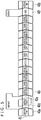
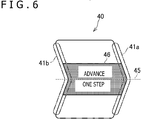
FIG. 5 is a view depicting an example ofmultiple command cards 40 being arrayed.FIG. 6 is a plan view explaining the shape of acommand card 40. - The
command cards 40 come in various types, such as acommand card 40a indicating the start of a program, acommand card 40b indicating the end of a program, acommand card 40i indicating an ordinary command, acommand card 40d indicating a subsequent repeat, acommand card 40f indicating the end of a repeat, and anadditional card 40e. Thecommand card 40d is furnished with an opening of approximately the same shape as that of theadditional card 40e in planar view. Theadditional card 40e is fitted into that opening. Here, theadditional card 40e indicates the number of repeats. As depicted inFIGS. 5 and6 , areference line 45 extended in the direction in which thecommand cards 40 are to be arrayed (i.e., reading direction) is defined on thecommand cards 40. Although not explicitly printed in the examples ofFIGS. 5 and6 , thereference line 45 indicates the regions of thecommand cards 40 in which thecarriage 20 travels, particularly the center of these regions. - Each
command card 40 includes a first end part configured to be adjacent to anthercommand card 40 in the reading direction; and a second end part configured to be on the opposite side of the first end part and adjacent to anothercommand card 40. The first end part is furnished with apositioning part 41a, and the second end part with apositioning part 41b. - In the examples of
FIGS. 5 and6 , thepositioning part 41a is a projected portion and thepositioning part 41b is a recessed portion in planar view. Thepositioning parts reference line 45 and thepositioning parts positioning parts reference line 45 on the other hand, regardless of the type ofcommand card 40. - The
command card 40 has a region between the first end part and the second end part thereof. In the example ofFIG. 6 , thecommand card 40 has a shape formed by an upper parallelogram and a lower parallelogram, the lower side of the upper parallelogram being connected with the upper side of the lower parallelogram. Thereference line 45 is located at or near the position where these two parallelograms are connected with each other. - Further, the upper surface of the
command card 40 is printed visibly with a marking 46 (hatched region) constituting a thick line and extended in such a manner as to overlap with thereference line 45. As with thesheet 31, the upper surface of thecommand card 40 is printed with a pattern in which the coordinates of the card in the coordinate space are coded. Unit patterns are arrayed on thecommand card 40. The unit pattern is an image in which are coded the coordinates of the position at which that unit pattern is placed. The coordinates assigned to the patterns will be discussed later in detail. - In the
positioning parts positioning parts command card 40d, either the first end part or the second end part alone (e.g., lower side inFIG. 5 ) may be furnished with thepositioning parts command card 40d is shaped in such a manner that the two parallelograms connected as depicted inFIG. 6 are supplemented with a region at an end part different from thepositioning parts FIG. 6 ). The added region may include a region protruded from the first end part in the reading direction. The protruded region is provided in a manner avoiding interference with the other types ofcommand cards 40. - The
positioning part 41a is regulated to engage with thepositioning part 41b of anothercommand card 40 adjacent to the first end part, thus keeping in position theother command card 40 in a direction intersecting with the reading direction. Also, thepositioning part 41b is regulated to engage with thepositioning part 41a of anothercommand card 40 adjacent to the second end part, thereby keeping theother command card 40 in position. Further, the marking 46 is regulated to let the user recognize more easily any positional displacement in the direction intersecting with the reading direction, thus keeping theadjacent command card 40 in position. Alternatively, either the shape of thepositioning parts - The present embodiment is further arranged in such a manner that not only the
command cards 40 are simply prevented from being misaligned but also the carriage is allowed to travel on the alignedcommand cards 40 without deviating therefrom. This arrangement is explained below. -
FIG. 7 is a block diagram depicting functions implemented by the control system. The control system includes, functionally, a currentposition acquisition section 51, astart control section 52, atravel control section 53, a hands-on practiceprogram execution section 54, and a cardinformation storage section 61. The currentposition acquisition section 51, thestart control section 52, and thetravel control section 53 are implemented mainly by theprocessor 11 in thedevice control apparatus 10 executing programs stored in thestorage section 12 so as to control thecarriage 20 via thecommunication section 13. Also, part or all of the functions of the currentposition acquisition section 51 are implemented by theprocessor 21 in thecarriage 20 executing programs stored in thestorage section 22 and exchanging data with thedevice control apparatus 10 via thecommunication section 23 to thereby control thecamera 24 and themotors 25. The cardinformation storage section 61 is a sort of database implemented by thestorage section 12 in thedevice control apparatus 10, the database storing information regarding thecommand cards 40. - From the image captured by the
camera 24, the currentposition acquisition section 51 acquires the pattern in which the coordinates are coded. Given the coordinates indicated by the pattern, the currentposition acquisition section 51 acquires the coordinates in which thecarriage 20 is positioned as well as the direction of thecarriage 20. - The
start control section 52 acquires from the currentposition acquisition section 51 the coordinates indicating the position at which thecarriage 20 is first placed. Thestart control section 52 then adjusts the position and direction of thecarriage 20 in such a manner that the sequence of arrayedcommand cards 40 can correctly be read in. - The
travel control section 53 controls the direction in which thecarriage 20 travels by successively reading thecommand cards 40 in sequence. - The hands-on practice
program execution section 54 executes the hands-on practice program designated by the sequence of the readcommand cards 40 so as to control the operation of thecarriage 20 placed on thesheet 31. -
FIG. 8 is a flowchart depicting a typical process of readingcommand cards 40. First, the currentposition acquisition section 51 acquires the current coordinates and direction of thecarriage 20 on the basis of the pattern captured by the camera 24 (step S101). - Next, the
start control section 52 determines whether or not the current coordinates and direction are within tolerable ranges for thecarriage 20 self-propelled to read the hands-on practice program (step S102). In the case where the current coordinates and direction are not in the tolerable ranges (N in step S02), thestart control section 52 moves thecarriage 20 into an appropriate position and direction (step S103). More specifically, thestart control section 52 may control themotors 25 in thecarriage 20 to let thecarriage 20 be self-propelled into the appropriate position and direction. Alternatively, thestart control section 52 may output toward the user a sound prompting the user to manually reposition thecarriage 20. In the case where the current coordinates and direction are within the tolerable ranges (Y in step S102), step S103 is skipped. - Next, the
travel control section 53 causes thecarriage 20 to travel in a set direction (step S104). The set direction is initially the reading direction but will be corrected by a process to be discussed later. From the image captured by thecamera 24, the currentposition acquisition section 51 recognizes the pattern in which the coordinates are coded. Given the coordinates indicated by the pattern, the currentposition acquisition section 51 acquires the coordinates (x, y) of a current position P at which thecarriage 20 is located and the direction of the carriage 20 (step S105). Then, thetravel control section 53 determines whether or not there is a difference in coordinates larger than a predetermined threshold value between a preceding position PP obtained previously by the currentposition acquisition section 51 on one hand and the current position P on the other hand (step S106). The predetermined threshold value is larger than a maximum distance that can be traveled with a measurement interval of the current position P but smaller than a minimum length of thecommand card 40 in the reading direction. In the case where the difference in coordinates between the preceding position PP and the current position P is larger than the predetermined threshold value (Y in step S106), thetravel control section 53 determines that thecarriage 20 has moved from a givencommand card 40 onto anothercommand card 40. Thetravel control section 53 determines from the current position P the type of thecommand card 40, i.e., the command of the hands-on practice program indicated by the coordinates of the current position P. Thetravel control section 53 stores the determined type of thecommand card 40 into the memory (step S107). In the case where the difference in coordinates between the preceding position PP and the current position P is smaller than the predetermined threshold value (N in step S106), thetravel control section 53 determines that thecommand card 40 on which thecarriage 20 is placed has not changed, and skips step S107. -
FIG. 9 is a view depicting an example of assigningcommand cards 40 with respect to a coordinate space. AlthoughFIG. 9 illustrates images of thecommand cards 40 for the purpose of simplified explanation, the information indicating the assignment of thecommand cards 40 relative to the coordinate space need only associate the regions with the types (commands) of thecommand cards 40. Also, the shapes of theactual command cards 40 need not be stored as the information indicative of their assignment. For example, the information indicating assignment may be information that associates a rectangular region enclosing acommand card 40 with the type of thatcommand card 40 indicated by that region. The broken lines inFIG. 9 denote thereference line 45 corresponding to each of thecommand cards 40. The y coordinate of thereference line 45 varies depending on thecommand card 40. In the coordinate space, allcommand cards 40 may be arrayed in the y direction in a straight line centering on thereference line 45. In this case, the y coordinate of thereference line 45 remains unchanged. As can be seen inFIG. 9 , the coordinates assigned to eachcommand card 40 in the coordinate space indicate its positional relation relative to thereference line 45. - As illustrated in
FIG. 9 , each ofmultiple command cards 40 is assigned its coordinates in the coordinate space. Also,FIG. 9 depicts acommand card 40k indicating a conditional branch, acommand card 40m indicating the end of a conditional branch, acommand card 40n indicating a branch in the case of an unmet condition, andadditional cards command card 40a indicating the start of a program, thecommand card 40b indicating the end of a program, thecommand card 40i indicating an ordinary command, thecommand card 40d indicating a subsequent repeat, thecommand card 40f indicating the end of a repeat, and theadditional card 40e. - After the processing of step S107 is terminated or after it is determined in step S106 that the difference between the positions is equal to or smaller than the threshold value, the
travel control section 53 acquires a parameter β indicative of thereference line 45 from the coordinates of the current position P. More specifically, thetravel control section 53 determines the region of thecommand card 40 to which the current position P belongs, and acquires the parameter β (here, y coordinate) of thereference line 45 corresponding to the determined region. - Then, the
travel control section 53 obtains the coordinates of a target position T (x + α, β), based on the current position P and on the parameter β. On the basis of the target position T and the current position P, thetravel control section 53 sets the direction of travel. -
FIG. 10 is a view explaining a method of controlling thecarriage 20.FIG. 10 depicts the current position P and the target position T in the coordinate space. A broken line of which the y coordinate is β corresponds to thereference line 45. Thetravel control section 53 calculates the direction toward the target position T. Thetravel control section 53 then changes parameters representing the amounts of rotation of the twomotors 25 driving thewheels 254 according to the difference between the current direction acquired in step S105 on one hand and the calculated direction on the other hand. This sets the direction in which thecarriage 20 is to travel. - As described above, the present embodiment uses the
command cards 40 printed with the patterns in which are coded the coordinates indicating the positional relation with respect to thereference line 45. Using thecommand cards 40, the embodiment controls thecarriage 20 so that thecarriage 20 does not deviate from thereference line 45, based on the positional relation between the coordinates indicated by the pattern of eachcommand card 40 captured by thecamera 24 of thecarriage 20 on one hand and thereference line 45 of thatcommand card 40 on the other hand. Because the positional relation between thepositioning parts command card 40 on one hand and thereference line 45 on the other hand remains unchanged, any positional displacement of thereference line 45 corresponding to eachcommand card 40 is prevented. This reduces the possibility of thecarriage 20 getting unstable and deviating fromcommand cards 40 when moving from onecommand card 40 to another adjacent thereto in the course of reading thecommand cards 40 in sequence. - Here, the cards from which the control system reads patterns need not be the command cards.
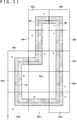
FIG. 11 is a view depicting an example of course cards 49 being arrayed. In the example ofFIG. 11 , a course is created using 9 types of course cards 49 ranging from acourse card 49a to acourse card 49i. Thecarriage 20 travels along this course. Each of the course cards 49 is a square. - As with the
command cards 40, thecourse cards FIG. 11 are each printed visibly with a marking 46 extended in the reading direction of thecarriage 20. Each of thecourse cards markings 46 are regulated to keep in position the other course cards 49 in a direction intersecting with the reading direction. Themarkings 46 at the first and the second end parts correspond to thepositioning parts reference line 45 and themarkings 46 have a predetermined positional relation therebetween. More specifically, there is a constant distance between a particular point in the marking 46 at the first end part and a specific point in the marking 46 at the second end part (e.g., the center of the end parts of the markings 46) on one hand and thereference line 45 on the other hand, regardless of the course card 49. - Also, the
course cards carriage 20 is caused to travel approximately along themarkings 46 by a process to be discussed later. Thus, over thecourse cards markings 46 also extend in the reading direction of thecarriage 20. The second end part corresponds to the location through which thecarriage 20 enters a given course card 49, and the first end part corresponds to the location through which thecarriage 20 moves on to another course card 49. For this reason, on thecourse cards first course cards markings 46 at the first and the second end parts correspond respectively to thepositioning parts reference line 45 and themarkings 46 have a predetermined positional relation therebetween. - As with the
command cards 40, the upper surfaces of the course cards 49 are printed with patterns in which the coordinates of the cards in a coordinate space are coded.FIG. 12 is a view depicting an example of assigning the course cards 49 with respect to the coordinate space. As illustrated inFIG. 12 , the course cards 49 are assigned their regions in a manner paving the coordinate space. Thereference line 45 is defined for each course card 49. Furthermore, the upper surfaces of thecourse cards markings 46 are bent are each divided by a bent boundary portion into aregion 48a and aregion 48b. Thelinear reference line 45 is provided in each of theregions reference lines 45 are connected with each other at the boundary between theregions - As depicted in
FIG. 11 , multiple course cards 49 of the same type (course cards FIG. 11 ) may be used. As can be seen inFIGS. 11 and12 , arraying the course cards 49 can bring about a more reduction in the size of the coordinate regions necessary for creating a course than if consecutive coordinate regions are assigned to the entire course. - Explained next is the process performed by the
travel control section 53 regarding the examples inFIGS. 11 and12 , with emphasis on the differences from the earlier example inFIG. 8 . In the current example, the start position is not clearly defined. Thus, instead of performing the processing of steps S102 and S103, thetravel control section 53 sets an initial traveling direction for thecarriage 20 on the basis of the current coordinates and direction. - In step S106, the
travel control section 53 determines that thecarriage 20 has moved onto another course card 49 not only in the case where the difference in coordinates between the preceding position PP and the current position P is larger than the threshold value but also where the difference between the preceding direction of thecarriage 20 and its current direction is larger than a direction threshold value. The direction threshold value is larger than 90 degrees. - In step S107, the
travel control section 53 determines the type of the course card 49. Thetravel control section 53 not only adds the determined type of the course card 49 into the memory but also acquires the advancing direction of thecarriage 20 on the basis of the coordinates of the current position P. More specifically, on the basis of the coordinates of the current position P, thetravel control section 53 determines that the first or the second end part of the course card 49 that is closer to the current position P than the other end part is the entrance side. Thetravel control section 53 then determines that thecarriage 20 advances from the entrance side end part toward a target side end part. - In the examples of
FIGS. 11 and12 , course cards 49 of the same type are arrayed end to end in some cases. Particularly, in a segment inFIG. 11 where thecourse cards 49e are continuously arrayed in the vertical direction, the bottom sides of the assigned coordinate regions are made adjacent to each other. In this case, the carriage movement from the precedingcourse card 49e onto thenext course card 49e cannot be sensed using solely the amount of change in coordinates. In such a case, the movement onto the next course card 49 can still be sensed by detecting differences of the direction of thecarriage 20 in the coordinate space. - In steps S108 and S109, the
travel control section 53 acquires the reference line according to the type of the course card 49 and the current position P. More specifically, in the case of straight-line course cards 49 such as thecourse card 49b, thetravel control section 53 acquires the center position of thereference line 45 and its extended direction. In the case of course cards 49 such as thecourse cards travel control section 53 determines whether the current position P is in theregion 48a or in theregion 48b and, depending on the determined region, acquires the center position of thereference line 45 and its extended direction inside that region. Then, on the basis of the advancing direction of thecarriage 20 and the coordinates of the current position, thetravel control section 53 calculates the target position in such a manner that the target position is in a direction in which thecarriage 20 moves closer to the target-side end part from the current position along thereference line 45 or its extended line. - The above-described steps allow the
carriage 20 to read the contour of the course. Here, thetravel control section 53 may determine whether or not thecarriage 20 is reading a given course card 49 placed at an overlapping position. In the case of the overlap, there is a high possibility that the course is a circuit course. Following the determination of the overlap, thetravel control section 53 may calculate a route along which thecarriage 20 will move more efficiently over the course cards 49, based on the read course, and perform control to let thecarriage 20 travel along the calculated route. Preferably, thetravel control section 53 may allow for more and more course cards 49 to be laid out in front of thecarriage 20 during traveling. - It should be noted that, instead of having the course cards 49 laid out, patterns similar to the arrayed course cards 49 may be printed. In this case, the advantageous effect of using the coordinate space efficiently is still made available.
Claims (6)
- A card comprising:a first end part configured to be adjacent to another card in a predetermined direction;a second end part configured to be on an opposite side of the first end part and adjacent to another card different from the first end part; anda surface printed with a pattern in which are coded coordinates indicating a positional relation relative to a reference line extended in the predetermined direction indicative of a region in which a self-propelled device is to travel,wherein each of the first and the second end parts has a positioning part regulating how the other card adjacent to the end part is to be placed, andthe positioning parts and the reference line have a predetermined positional relation.
- The card according to claim 1, wherein the positioning part belonging to one of the first and the second end parts has a recessed portion and the positioning part belonging to the other end part has a projected portion in planar view.
- The card according to claim 1 or 2, wherein the surface is printed with a line extended in the predetermined direction to constitute the positioning parts.
- The card according to any one of claims 1 to 3, further comprising:an opening configured to intersect with the reference line in planar view,wherein an additional card printed with a pattern in which are coded the coordinates indicating the positional relation relative to the reference line is fitted into the opening.
- A card reading system comprising:a current position acquisition means configured to acquire a current position of a self-propelled device by recognizing a pattern printed on a card having a first end part and a second end part, the first end part having a positioning part regulating how another card adjacent to the first end part in a predetermined direction is to be placed, the second end part having a positioning part located on an opposite side of the first end part to regulate how another card adjacent to the second end part is to be placed, the pattern being one in which are coded coordinates indicating a positional relation relative to a reference line extended in the predetermined direction; anda travel control section configured to control the self-propelled device to travel, on a basis of the acquired current position and the reference line.
- A card set comprising a plurality of cards configured to be arrayed in a predetermined direction, each of the cards including:a first end part configured to be adjacent to another card;a second end part configured to be on an opposite side of the first end part and adjacent to another card different from the first end part; anda surface printed with a pattern in which are coded coordinates indicating a positional relation relative to a reference line extended in the predetermined direction indicative of a region in which a self-propelled device is to travel,wherein each of the first and the second end parts has a positioning part regulating how the other card adjacent to the end part is to be placed, andthe positioning parts and the reference line have a predetermined positional relation.
Applications Claiming Priority (2)
| Application Number | Priority Date | Filing Date | Title |
|---|---|---|---|
| JP2018153623 | 2018-08-17 | ||
| PCT/JP2019/031681 WO2020036146A1 (en) | 2018-08-17 | 2019-08-09 | Cards, card reading system, and card set |
Publications (3)
| Publication Number | Publication Date |
|---|---|
| EP3838361A1 true EP3838361A1 (en) | 2021-06-23 |
| EP3838361A4 EP3838361A4 (en) | 2022-05-25 |
| EP3838361B1 EP3838361B1 (en) | 2023-09-27 |
Family
ID=69525356
Family Applications (1)
| Application Number | Title | Priority Date | Filing Date |
|---|---|---|---|
| EP19849490.8A Active EP3838361B1 (en) | 2018-08-17 | 2019-08-09 | Cards, card reading system, and card set |
Country Status (5)
| Country | Link |
|---|---|
| US (1) | US11498013B2 (en) |
| EP (1) | EP3838361B1 (en) |
| JP (1) | JP7022834B2 (en) |
| CN (1) | CN112584907A (en) |
| WO (1) | WO2020036146A1 (en) |
Families Citing this family (2)
| Publication number | Priority date | Publication date | Assignee | Title |
|---|---|---|---|---|
| CN114571482B (en) * | 2022-03-30 | 2023-11-03 | 长沙朗源电子科技有限公司 | Painting robot system and control method of painting robot |
| USD992638S1 (en) * | 2022-08-03 | 2023-07-18 | Shenzhen Lute Jiacheng Supply Chain Management Co., Ltd. | LED music device for dance mat |
Family Cites Families (16)
| Publication number | Priority date | Publication date | Assignee | Title |
|---|---|---|---|---|
| US6012957A (en) * | 1997-10-27 | 2000-01-11 | Parvia Corporation | Single beam optoelectric remote control apparatus for control of toys |
| JP2001228963A (en) | 2000-02-17 | 2001-08-24 | Kaikousha:Kk | Panel recognizing device |
| US6695668B2 (en) | 2001-01-29 | 2004-02-24 | Kevin Gerard Donahue | Toy vehicle and method of controlling a toy vehicle from a printed track |
| DE102006023131B4 (en) * | 2006-05-17 | 2017-02-02 | Stadlbauer Marketing und Vertrieb GmbH | Method for switching points in a digital control system for track-guided toy vehicles |
| KR100878038B1 (en) | 2008-06-11 | 2009-01-13 | 주식회사 씽코웰 | Child Learning Mat |
| US8245807B2 (en) | 2009-02-12 | 2012-08-21 | Edison Nation, Llc | Automated vehicle and system utilizing an optical sensing system |
| EP2435149B1 (en) * | 2009-05-28 | 2015-07-08 | Anki, Inc. | Distributed system of autonomously controlled toy vehicles |
| GB2482119B (en) * | 2010-07-19 | 2013-01-23 | China Ind Ltd | Racing vehicle game |
| US20170007915A1 (en) * | 2015-07-10 | 2017-01-12 | Play Works Studio, Inc. | Systems and methods for an interactive robotic game |
| US10885801B2 (en) * | 2016-05-24 | 2021-01-05 | Tangible Play, Inc. | Virtualized tangible programming |
| JP6995754B2 (en) * | 2016-08-04 | 2022-01-17 | 株式会社ソニー・インタラクティブエンタテインメント | Information processing equipment, information processing methods, toy systems, toys, and information media |
| EP3282327A1 (en) * | 2016-08-12 | 2018-02-14 | KUBO Robotics ApS | Programmable robot for educational purposes |
| CN106504614B (en) * | 2016-12-01 | 2022-07-26 | 华南理工大学 | Educational robot with building block programming |
| TWM560329U (en) * | 2017-12-08 | 2018-05-21 | 江明仁 | Educational toy |
| JP3215614U (en) | 2017-12-20 | 2018-04-05 | 安譜國際股▲分▼有限公司 | Educational toys |
| TWM563908U (en) * | 2018-01-25 | 2018-07-21 | 智高實業股份有限公司 | Programming toy module |
-
2019
- 2019-08-09 EP EP19849490.8A patent/EP3838361B1/en active Active
- 2019-08-09 US US17/267,233 patent/US11498013B2/en active Active
- 2019-08-09 CN CN201980054466.0A patent/CN112584907A/en active Pending
- 2019-08-09 JP JP2020537071A patent/JP7022834B2/en active Active
- 2019-08-09 WO PCT/JP2019/031681 patent/WO2020036146A1/en not_active Ceased
Also Published As
| Publication number | Publication date |
|---|---|
| US20210162310A1 (en) | 2021-06-03 |
| US11498013B2 (en) | 2022-11-15 |
| EP3838361B1 (en) | 2023-09-27 |
| JP7022834B2 (en) | 2022-02-18 |
| WO2020036146A1 (en) | 2020-02-20 |
| JPWO2020036146A1 (en) | 2021-04-30 |
| EP3838361A4 (en) | 2022-05-25 |
| CN112584907A (en) | 2021-03-30 |
Similar Documents
| Publication | Publication Date | Title |
|---|---|---|
| CN106708051B (en) | Navigation system and method based on two-dimensional code, navigation marker and navigation controller | |
| CN106054878B (en) | Inertial guidance vehicle navigation method based on two-dimensional code positioning and inertial guidance vehicle | |
| US10857673B2 (en) | Device, method, program and recording medium, for simulation of article arraying operation performed by robot | |
| EP3838361B1 (en) | Cards, card reading system, and card set | |
| EP3566821A1 (en) | Robot movement control method, and robot | |
| US12304058B2 (en) | Autonomous working system, method and computer readable recording medium | |
| CN111474930B (en) | A tracking control method, device, equipment and medium based on visual positioning | |
| JP2743613B2 (en) | Control method of mobile robot | |
| TW202105109A (en) | Mobile robot, mobile robot control system, and mobile robot control method | |
| JP2018092393A (en) | Automated guided vehicle control system | |
| KR20170009103A (en) | Autonomously traveling robot and navigation method thereof | |
| US20180236664A1 (en) | Workpiece pick up system | |
| CN103776455A (en) | Infrared discrete light source tracing navigation system and control method thereof | |
| JPH0854927A (en) | Landmark determination method and apparatus | |
| KR20160056559A (en) | Traveling system and method of robot using a pointer | |
| JPH07302118A (en) | Control method of automatic moving unit | |
| CN105929834B (en) | Visual guidance vehicle localization method based on auxiliary locator and visual guidance vehicle | |
| JP2009032185A (en) | Moving route acquisition device | |
| JPH01243104A (en) | Mark identifying device in image pickup means | |
| JPH01197808A (en) | Guidance system for unmanned vehicle | |
| CN110977984B (en) | Control strip, mechanical arm control method, device, system and storage medium | |
| US20210141390A1 (en) | Autonomous travel system | |
| US11957989B2 (en) | Control system, control method, and program | |
| CN111300409A (en) | Industrial robot path planning method | |
| CN118254483A (en) | Laser printing control method and system |
Legal Events
| Date | Code | Title | Description |
|---|---|---|---|
| STAA | Information on the status of an ep patent application or granted ep patent |
Free format text: STATUS: THE INTERNATIONAL PUBLICATION HAS BEEN MADE |
|
| PUAI | Public reference made under article 153(3) epc to a published international application that has entered the european phase |
Free format text: ORIGINAL CODE: 0009012 |
|
| STAA | Information on the status of an ep patent application or granted ep patent |
Free format text: STATUS: REQUEST FOR EXAMINATION WAS MADE |
|
| 17P | Request for examination filed |
Effective date: 20210127 |
|
| AK | Designated contracting states |
Kind code of ref document: A1 Designated state(s): AL AT BE BG CH CY CZ DE DK EE ES FI FR GB GR HR HU IE IS IT LI LT LU LV MC MK MT NL NO PL PT RO RS SE SI SK SM TR |
|
| DAV | Request for validation of the european patent (deleted) | ||
| DAX | Request for extension of the european patent (deleted) | ||
| A4 | Supplementary search report drawn up and despatched |
Effective date: 20220426 |
|
| RIC1 | Information provided on ipc code assigned before grant |
Ipc: A63H 33/26 20060101ALI20220420BHEP Ipc: A63H 30/04 20060101ALI20220420BHEP Ipc: A63H 17/395 20060101ALI20220420BHEP Ipc: A63F 1/02 20060101ALI20220420BHEP Ipc: G09B 19/00 20060101ALI20220420BHEP Ipc: G09B 1/10 20060101ALI20220420BHEP Ipc: B42D 15/00 20060101ALI20220420BHEP Ipc: A63H 33/08 20060101ALI20220420BHEP Ipc: A63H 18/02 20060101ALI20220420BHEP Ipc: A63H 18/16 20060101AFI20220420BHEP |
|
| GRAP | Despatch of communication of intention to grant a patent |
Free format text: ORIGINAL CODE: EPIDOSNIGR1 |
|
| STAA | Information on the status of an ep patent application or granted ep patent |
Free format text: STATUS: GRANT OF PATENT IS INTENDED |
|
| INTG | Intention to grant announced |
Effective date: 20230404 |
|
| GRAS | Grant fee paid |
Free format text: ORIGINAL CODE: EPIDOSNIGR3 |
|
| GRAA | (expected) grant |
Free format text: ORIGINAL CODE: 0009210 |
|
| STAA | Information on the status of an ep patent application or granted ep patent |
Free format text: STATUS: THE PATENT HAS BEEN GRANTED |
|
| P01 | Opt-out of the competence of the unified patent court (upc) registered |
Effective date: 20230816 |
|
| AK | Designated contracting states |
Kind code of ref document: B1 Designated state(s): AL AT BE BG CH CY CZ DE DK EE ES FI FR GB GR HR HU IE IS IT LI LT LU LV MC MK MT NL NO PL PT RO RS SE SI SK SM TR |
|
| REG | Reference to a national code |
Ref country code: GB Ref legal event code: FG4D |
|
| REG | Reference to a national code |
Ref country code: CH Ref legal event code: EP |
|
| REG | Reference to a national code |
Ref country code: DE Ref legal event code: R096 Ref document number: 602019038377 Country of ref document: DE |
|
| REG | Reference to a national code |
Ref country code: IE Ref legal event code: FG4D |
|
| REG | Reference to a national code |
Ref country code: LT Ref legal event code: MG9D |
|
| PG25 | Lapsed in a contracting state [announced via postgrant information from national office to epo] |
Ref country code: GR Free format text: LAPSE BECAUSE OF FAILURE TO SUBMIT A TRANSLATION OF THE DESCRIPTION OR TO PAY THE FEE WITHIN THE PRESCRIBED TIME-LIMIT Effective date: 20231228 |
|
| PG25 | Lapsed in a contracting state [announced via postgrant information from national office to epo] |
Ref country code: SE Free format text: LAPSE BECAUSE OF FAILURE TO SUBMIT A TRANSLATION OF THE DESCRIPTION OR TO PAY THE FEE WITHIN THE PRESCRIBED TIME-LIMIT Effective date: 20230927 Ref country code: RS Free format text: LAPSE BECAUSE OF FAILURE TO SUBMIT A TRANSLATION OF THE DESCRIPTION OR TO PAY THE FEE WITHIN THE PRESCRIBED TIME-LIMIT Effective date: 20230927 Ref country code: NO Free format text: LAPSE BECAUSE OF FAILURE TO SUBMIT A TRANSLATION OF THE DESCRIPTION OR TO PAY THE FEE WITHIN THE PRESCRIBED TIME-LIMIT Effective date: 20231227 Ref country code: LV Free format text: LAPSE BECAUSE OF FAILURE TO SUBMIT A TRANSLATION OF THE DESCRIPTION OR TO PAY THE FEE WITHIN THE PRESCRIBED TIME-LIMIT Effective date: 20230927 Ref country code: LT Free format text: LAPSE BECAUSE OF FAILURE TO SUBMIT A TRANSLATION OF THE DESCRIPTION OR TO PAY THE FEE WITHIN THE PRESCRIBED TIME-LIMIT Effective date: 20230927 Ref country code: HR Free format text: LAPSE BECAUSE OF FAILURE TO SUBMIT A TRANSLATION OF THE DESCRIPTION OR TO PAY THE FEE WITHIN THE PRESCRIBED TIME-LIMIT Effective date: 20230927 Ref country code: GR Free format text: LAPSE BECAUSE OF FAILURE TO SUBMIT A TRANSLATION OF THE DESCRIPTION OR TO PAY THE FEE WITHIN THE PRESCRIBED TIME-LIMIT Effective date: 20231228 Ref country code: FI Free format text: LAPSE BECAUSE OF FAILURE TO SUBMIT A TRANSLATION OF THE DESCRIPTION OR TO PAY THE FEE WITHIN THE PRESCRIBED TIME-LIMIT Effective date: 20230927 |
|
| REG | Reference to a national code |
Ref country code: NL Ref legal event code: MP Effective date: 20230927 |
|
| REG | Reference to a national code |
Ref country code: AT Ref legal event code: MK05 Ref document number: 1614837 Country of ref document: AT Kind code of ref document: T Effective date: 20230927 |
|
| PG25 | Lapsed in a contracting state [announced via postgrant information from national office to epo] |
Ref country code: NL Free format text: LAPSE BECAUSE OF FAILURE TO SUBMIT A TRANSLATION OF THE DESCRIPTION OR TO PAY THE FEE WITHIN THE PRESCRIBED TIME-LIMIT Effective date: 20230927 |
|
| PG25 | Lapsed in a contracting state [announced via postgrant information from national office to epo] |
Ref country code: IS Free format text: LAPSE BECAUSE OF FAILURE TO SUBMIT A TRANSLATION OF THE DESCRIPTION OR TO PAY THE FEE WITHIN THE PRESCRIBED TIME-LIMIT Effective date: 20240127 |
|
| PG25 | Lapsed in a contracting state [announced via postgrant information from national office to epo] |
Ref country code: AT Free format text: LAPSE BECAUSE OF FAILURE TO SUBMIT A TRANSLATION OF THE DESCRIPTION OR TO PAY THE FEE WITHIN THE PRESCRIBED TIME-LIMIT Effective date: 20230927 |
|
| PG25 | Lapsed in a contracting state [announced via postgrant information from national office to epo] |
Ref country code: ES Free format text: LAPSE BECAUSE OF FAILURE TO SUBMIT A TRANSLATION OF THE DESCRIPTION OR TO PAY THE FEE WITHIN THE PRESCRIBED TIME-LIMIT Effective date: 20230927 |
|
| PG25 | Lapsed in a contracting state [announced via postgrant information from national office to epo] |
Ref country code: SM Free format text: LAPSE BECAUSE OF FAILURE TO SUBMIT A TRANSLATION OF THE DESCRIPTION OR TO PAY THE FEE WITHIN THE PRESCRIBED TIME-LIMIT Effective date: 20230927 Ref country code: RO Free format text: LAPSE BECAUSE OF FAILURE TO SUBMIT A TRANSLATION OF THE DESCRIPTION OR TO PAY THE FEE WITHIN THE PRESCRIBED TIME-LIMIT Effective date: 20230927 Ref country code: IS Free format text: LAPSE BECAUSE OF FAILURE TO SUBMIT A TRANSLATION OF THE DESCRIPTION OR TO PAY THE FEE WITHIN THE PRESCRIBED TIME-LIMIT Effective date: 20240127 Ref country code: ES Free format text: LAPSE BECAUSE OF FAILURE TO SUBMIT A TRANSLATION OF THE DESCRIPTION OR TO PAY THE FEE WITHIN THE PRESCRIBED TIME-LIMIT Effective date: 20230927 Ref country code: EE Free format text: LAPSE BECAUSE OF FAILURE TO SUBMIT A TRANSLATION OF THE DESCRIPTION OR TO PAY THE FEE WITHIN THE PRESCRIBED TIME-LIMIT Effective date: 20230927 Ref country code: CZ Free format text: LAPSE BECAUSE OF FAILURE TO SUBMIT A TRANSLATION OF THE DESCRIPTION OR TO PAY THE FEE WITHIN THE PRESCRIBED TIME-LIMIT Effective date: 20230927 Ref country code: AT Free format text: LAPSE BECAUSE OF FAILURE TO SUBMIT A TRANSLATION OF THE DESCRIPTION OR TO PAY THE FEE WITHIN THE PRESCRIBED TIME-LIMIT Effective date: 20230927 Ref country code: PT Free format text: LAPSE BECAUSE OF FAILURE TO SUBMIT A TRANSLATION OF THE DESCRIPTION OR TO PAY THE FEE WITHIN THE PRESCRIBED TIME-LIMIT Effective date: 20240129 Ref country code: SK Free format text: LAPSE BECAUSE OF FAILURE TO SUBMIT A TRANSLATION OF THE DESCRIPTION OR TO PAY THE FEE WITHIN THE PRESCRIBED TIME-LIMIT Effective date: 20230927 |
|
| PG25 | Lapsed in a contracting state [announced via postgrant information from national office to epo] |
Ref country code: PL Free format text: LAPSE BECAUSE OF FAILURE TO SUBMIT A TRANSLATION OF THE DESCRIPTION OR TO PAY THE FEE WITHIN THE PRESCRIBED TIME-LIMIT Effective date: 20230927 Ref country code: IT Free format text: LAPSE BECAUSE OF FAILURE TO SUBMIT A TRANSLATION OF THE DESCRIPTION OR TO PAY THE FEE WITHIN THE PRESCRIBED TIME-LIMIT Effective date: 20230927 |
|
| REG | Reference to a national code |
Ref country code: DE Ref legal event code: R097 Ref document number: 602019038377 Country of ref document: DE |
|
| PG25 | Lapsed in a contracting state [announced via postgrant information from national office to epo] |
Ref country code: DK Free format text: LAPSE BECAUSE OF FAILURE TO SUBMIT A TRANSLATION OF THE DESCRIPTION OR TO PAY THE FEE WITHIN THE PRESCRIBED TIME-LIMIT Effective date: 20230927 |
|
| PG25 | Lapsed in a contracting state [announced via postgrant information from national office to epo] |
Ref country code: DK Free format text: LAPSE BECAUSE OF FAILURE TO SUBMIT A TRANSLATION OF THE DESCRIPTION OR TO PAY THE FEE WITHIN THE PRESCRIBED TIME-LIMIT Effective date: 20230927 |
|
| PLBE | No opposition filed within time limit |
Free format text: ORIGINAL CODE: 0009261 |
|
| STAA | Information on the status of an ep patent application or granted ep patent |
Free format text: STATUS: NO OPPOSITION FILED WITHIN TIME LIMIT |
|
| 26N | No opposition filed |
Effective date: 20240628 |
|
| PG25 | Lapsed in a contracting state [announced via postgrant information from national office to epo] |
Ref country code: SI Free format text: LAPSE BECAUSE OF FAILURE TO SUBMIT A TRANSLATION OF THE DESCRIPTION OR TO PAY THE FEE WITHIN THE PRESCRIBED TIME-LIMIT Effective date: 20230927 |
|
| PG25 | Lapsed in a contracting state [announced via postgrant information from national office to epo] |
Ref country code: SI Free format text: LAPSE BECAUSE OF FAILURE TO SUBMIT A TRANSLATION OF THE DESCRIPTION OR TO PAY THE FEE WITHIN THE PRESCRIBED TIME-LIMIT Effective date: 20230927 |
|
| PG25 | Lapsed in a contracting state [announced via postgrant information from national office to epo] |
Ref country code: BG Free format text: LAPSE BECAUSE OF FAILURE TO SUBMIT A TRANSLATION OF THE DESCRIPTION OR TO PAY THE FEE WITHIN THE PRESCRIBED TIME-LIMIT Effective date: 20230927 |
|
| PG25 | Lapsed in a contracting state [announced via postgrant information from national office to epo] |
Ref country code: BG Free format text: LAPSE BECAUSE OF FAILURE TO SUBMIT A TRANSLATION OF THE DESCRIPTION OR TO PAY THE FEE WITHIN THE PRESCRIBED TIME-LIMIT Effective date: 20230927 |
|
| REG | Reference to a national code |
Ref country code: CH Ref legal event code: PL |
|
| PG25 | Lapsed in a contracting state [announced via postgrant information from national office to epo] |
Ref country code: LU Free format text: LAPSE BECAUSE OF NON-PAYMENT OF DUE FEES Effective date: 20240809 |
|
| PG25 | Lapsed in a contracting state [announced via postgrant information from national office to epo] |
Ref country code: MC Free format text: LAPSE BECAUSE OF FAILURE TO SUBMIT A TRANSLATION OF THE DESCRIPTION OR TO PAY THE FEE WITHIN THE PRESCRIBED TIME-LIMIT Effective date: 20230927 Ref country code: CH Free format text: LAPSE BECAUSE OF NON-PAYMENT OF DUE FEES Effective date: 20240831 |
|
| REG | Reference to a national code |
Ref country code: BE Ref legal event code: MM Effective date: 20240831 |
|
| PG25 | Lapsed in a contracting state [announced via postgrant information from national office to epo] |
Ref country code: BE Free format text: LAPSE BECAUSE OF NON-PAYMENT OF DUE FEES Effective date: 20240831 |
|
| PG25 | Lapsed in a contracting state [announced via postgrant information from national office to epo] |
Ref country code: IE Free format text: LAPSE BECAUSE OF NON-PAYMENT OF DUE FEES Effective date: 20240809 |
|
| PGFP | Annual fee paid to national office [announced via postgrant information from national office to epo] |
Ref country code: DE Payment date: 20250724 Year of fee payment: 7 |
|
| PGFP | Annual fee paid to national office [announced via postgrant information from national office to epo] |
Ref country code: GB Payment date: 20250725 Year of fee payment: 7 |
|
| PGFP | Annual fee paid to national office [announced via postgrant information from national office to epo] |
Ref country code: FR Payment date: 20250723 Year of fee payment: 7 |
|
| PG25 | Lapsed in a contracting state [announced via postgrant information from national office to epo] |
Ref country code: CY Free format text: LAPSE BECAUSE OF FAILURE TO SUBMIT A TRANSLATION OF THE DESCRIPTION OR TO PAY THE FEE WITHIN THE PRESCRIBED TIME-LIMIT; INVALID AB INITIO Effective date: 20190809 |
|
| PG25 | Lapsed in a contracting state [announced via postgrant information from national office to epo] |
Ref country code: HU Free format text: LAPSE BECAUSE OF FAILURE TO SUBMIT A TRANSLATION OF THE DESCRIPTION OR TO PAY THE FEE WITHIN THE PRESCRIBED TIME-LIMIT; INVALID AB INITIO Effective date: 20190809 |