EP3838063B1 - Ski rack system - Google Patents
Ski rack system Download PDFInfo
- Publication number
- EP3838063B1 EP3838063B1 EP20215343.3A EP20215343A EP3838063B1 EP 3838063 B1 EP3838063 B1 EP 3838063B1 EP 20215343 A EP20215343 A EP 20215343A EP 3838063 B1 EP3838063 B1 EP 3838063B1
- Authority
- EP
- European Patent Office
- Prior art keywords
- skis
- pair
- support
- shoulder strap
- ski
- Prior art date
- Legal status (The legal status is an assumption and is not a legal conclusion. Google has not performed a legal analysis and makes no representation as to the accuracy of the status listed.)
- Active
Links
Images


Classifications
-
- A—HUMAN NECESSITIES
- A63—SPORTS; GAMES; AMUSEMENTS
- A63C—SKATES; SKIS; ROLLER SKATES; DESIGN OR LAYOUT OF COURTS, RINKS OR THE LIKE
- A63C11/00—Accessories for skiing or snowboarding
- A63C11/02—Devices for stretching, clamping or pressing skis or snowboards for transportation or storage
- A63C11/023—Carrying-devices
- A63C11/025—Carrying-devices for skis or ski-sticks
-
- A—HUMAN NECESSITIES
- A45—HAND OR TRAVELLING ARTICLES
- A45F—TRAVELLING OR CAMP EQUIPMENT: SACKS OR PACKS CARRIED ON THE BODY
- A45F3/00—Travelling or camp articles; Sacks or packs carried on the body
- A45F3/04—Sacks or packs carried on the body by means of two straps passing over the two shoulders
- A45F3/08—Carrying-frames; Frames combined with sacks
-
- A—HUMAN NECESSITIES
- A45—HAND OR TRAVELLING ARTICLES
- A45F—TRAVELLING OR CAMP EQUIPMENT: SACKS OR PACKS CARRIED ON THE BODY
- A45F3/00—Travelling or camp articles; Sacks or packs carried on the body
- A45F3/14—Carrying-straps; Pack-carrying harnesses
-
- A—HUMAN NECESSITIES
- A45—HAND OR TRAVELLING ARTICLES
- A45F—TRAVELLING OR CAMP EQUIPMENT: SACKS OR PACKS CARRIED ON THE BODY
- A45F3/00—Travelling or camp articles; Sacks or packs carried on the body
- A45F3/14—Carrying-straps; Pack-carrying harnesses
- A45F2003/146—Pack-carrying harnesses
Definitions
- Ski mountaineering is a sporting activity, even competitive, consisting of climbing snowy slopes, with skis on or over the shoulders.
- Such ski rack systems generally comprise a frame, a pair of shoulder straps, and means for supporting and fixing the skis, in particular, at the back of the athlete.
- Known skis supporting and fixing means comprise a lower ski rack support, configured as a semi-rigid annular cord, inside which a lower portion of the pair of skis is inserted and supported.
- Such means further comprise an upper ski rack support, configured as a hook adapted to couple an upper portion of the pair of skis.
- the upper ski rack may not be immediately handled by the athlete, who, especially in a competitive environment, loses precious seconds to look for it and then handle it. Even more time is wasted when the upper ski rack is caught in the ski rack system, since it is necessary, first of all, to untangle it from the ski rack system to then be able to handle it.
- a ski rack system is generally indicated with reference numeral 1.
- the system for carrying skis 1 is adapted to be worn over the shoulders by a user, or an athlete 2, and is further configured for the transport of a pair of skis 3 over the shoulders.
- the system for carrying skis 1 comprises a frame 4, a first shoulder strap 5 and a second shoulder strap 6.
- the first shoulder strap 5 and the second shoulder strap 6 are connected to the frame 4.
- An upper end 7 of the first shoulder strap 5 is connected to a first upper portion 8 of the frame 4.
- a lower end 9 of the first shoulder strap 5 is connected to a first lower portion 10 of the frame 4.
- An upper end 11 of the second shoulder strap 6 is connected to a second upper portion 12 of the frame 4.
- a lower end 13 of the second shoulder strap 6 is connected to a second lower portion 14 of the frame 4.
- the system for carrying skis 1 further comprises a lower ski rack support 15, positioned at the first lower portion 10 of the frame 4.
- the system for carrying skis 1 further comprises an upper ski rack support 16, positioned at the second shoulder strap 6.
- the upper ski rack support 16 comprises a hook 18 elastically connected to the second shoulder strap 6 by means of an elastic return element 19.
- a covering 20 is connected to the second shoulder strap 6, so that the covering 20 and the second shoulder strap 6 delimit a guide duct 21 extending from the upper end 11 to the lower end 13 of the second shoulder strap 6, i.e., in the direction of the length of the second shoulder strap 6.
- the elastic return element 19 extends through the guide duct 21 formed by the covering 20 and the second shoulder strap 6.
- the elastic return element 19 and the hook 18 connected thereto are constrained to the second shoulder strap 6 and the elastic return element 19, connected to the hook 18, is therefore prevented from getting caught on the system for carrying skis 1 worn by the athlete 2.
- the elastic return element 19 is configured as a cord, in particular a spiral cord.
- a contrast element 22 is integrally connected to the covering 20 and to the second shoulder strap 6, at the upper end 11 of the second shoulder strap 6.
- the contrast element 22 forms a central through hole 23, through which the elastic return element 19 connected to the hook 18 extends.
- the contrast element 22 and the central through hole 23 are sized so that the elastic element 19 may slide inside the central through hole 23, and the hook 18 may partially be inserted into the central through hole 23 but cannot cross the central through hole 23.
- the hook 18, when it is not in use or when it is not fixed to the pair of skis 3, is elastically constrained so as to partially extend outside the guide duct 21, and therefore be readily available for the athlete 2 who intended to grab and handle it.
- the elastic return element 19 returns the hook 18 towards the contrast element 22, so that the elastic hook 18 is partially inserted into the central through hole 23 and partially protrudes from the guide duct 21.
- the elastic return element 19 independently repositions the hook 18, when released from the connection to the pair of skis 3.
- the contrast element 22 forms a first slot 24, for the passage of first connection means 27 for a connection between the contrast element 22 and the covering 20, and a second slot 25 for the passage of second connection means 28 for a connection between the contrast element 22 and the second shoulder strap 6.
- first slot 24 and the second slot 25 ensure a firm and simple connection between the contrast element 22 and the covering 20 and the second shoulder strap 6.
- the elastic return element 19 slides inside a tubular covering made of a polymeric material 26.
- the polymeric material 26 protects the elastic return element 19 from any damage and/or tearing.
- this comprises a rigid annular element.
- the rigid annular element forms an annular opening which defines a threading direction, for threading a lower portion of the pair of skis 3 inside the rigid annular element.
- the rigid annular element is further configured to vertically support the pair of skis 3, and, in particular, to support the attachments of the pair of skis 3.
- the rigid annular element allows to insert a lower portion of the pair of skis 3 inside the rigid annular element along a threading direction parallel to the length direction of the pair of skis 3.
- the lower ski rack support 15 comprises a support element 30 in the shape of an open channel and having two ends 31, 31'.
- the support element 30 forms a first opening 33 defining a first insertion direction 34.
- the two ends 31, 31' of the support element 30 form a second opening 35 defining a second insertion direction 36 transversal to the first insertion direction 34.
- the lower ski rack support 15 further comprises a closing element 32.
- the closing element 32 extends between the two ends 31, 31' of the support element 30.
- the closing element 32 may be moved between a closing position, in which the second opening 35 closes, and an opening position, in which the second opening 35 opens.
- a system for carrying skis 1 thus configured ensures an easy, comfortable and less physically challenging support and fixing of a pair of skis 3 to the system for carrying skis 1, and, in particular, with reference to the insertion, support and fixing of a lower portion of the pair of skis 3.
- the possibility of introducing the pair of skis 3, and, in particular, the lower portion of the pair of skis 3, through the second opening 35 along the second insertion direction 36 avoids having to lift the pair of skis 3 to a height from the ground higher than that at which the lower ski rack support 15 is located.
- the second insertion direction 36 is advantageously horizontal, therefore it allows to insert the pair of skis 3, which extend in length along a length direction, inside the lower ski rack support 15 along a direction transversal to the direction of the extension in length of the pair of skis 3, thus reducing the complexity, the effort and the time required to insert the pair of skis 3 inside the lower ski rack support 15.
- the first insertion direction 34 is vertical, therefore it is still possible to insert the pair of skis 3 into the lower ski rack support 15 also from top downwards.
- the support element 30 of the lower ski rack support 15 forms a vertical support wall 37 configured to support the pair of skis 3 vertically, and, in particular, to support the attachments of the pair of skis 3.
- the closing element 32 consists of a spring element 38.
- the spring element 38 is hinged to one of the two ends 31, 31' of the support element 30, and is elastically biased against the other of the two ends 31, 31' of the support element 30, to a closing position, so as to close the second opening 35.
- the spring element 38 is rotatable towards the interior of the lower ski rack support 15, towards the opening position, so as to open the second opening 35.
- the spring element 38 automatically closes, locking the pair of skis 3 inside the lower ski rack support 15.
- the spring element 38 is configured to rotate towards the outside of the lower ski rack support 15.
- the first shoulder strap 5 corresponds to a right shoulder strap and the second shoulder strap 6 corresponds to a left shoulder strap.
- the first shoulder strap 5 corresponds to the left shoulder strap and the second shoulder strap 6 corresponds to the right shoulder strap.
- a ski backpack 17 comprises the system for carrying skis 1 described above.
- the ski backpack 17 has two shoulder straps which correspond, respectively, to the first shoulder strap 5 and to the second shoulder strap 6.
- the ski backpack 17 may comprise one or more housings or systems for containing and/or transporting one or more further ski mountaineering tools, such as, for example, a helmet, an ice ax, crampons, and other material useful to the sportsman or athlete.
- a method for securing and supporting a pair of skis 3, extending along a length direction, and having attachments, on the back of an athlete 2 comprises the following steps:
- a method for securing and supporting a pair of skis 3, extending along a length direction and having attachments, on the back of an athlete 2 comprises the following steps:
- a method for securing and supporting a pair of skis 3, extending along a length direction, and having attachments, on the back of an athlete 2 comprises the following steps:
- a method for securing and supporting a pair of skis 3, extending along a length direction and having attachments, on the back of an athlete 2 comprises the following steps:
Landscapes
- Purses, Travelling Bags, Baskets, Or Suitcases (AREA)
Description
- The present application claims the priority right of the
Italian patent application 102019000024466 of 12/18/2020 - The present invention relates to a system for carrying skis, in particular, for fixing and transporting skis on the back of an athlete.
- Ski mountaineering is a sporting activity, even competitive, consisting of climbing snowy slopes, with skis on or over the shoulders.
- This involves the need, for an athlete practicing such activity, to take off and transport the skis during the journeys on foot, and to reattach them when desired.
- For this purpose it is known for athletes to have ski rack systems adapted to support the skis when not in use.
- Such ski rack systems generally comprise a frame, a pair of shoulder straps, and means for supporting and fixing the skis, in particular, at the back of the athlete.
- Known skis supporting and fixing means comprise a lower ski rack support, configured as a semi-rigid annular cord, inside which a lower portion of the pair of skis is inserted and supported.
- Such means further comprise an upper ski rack support, configured as a hook adapted to couple an upper portion of the pair of skis.
- Thereby, the pair of skis is supported and fixed on the ski rack by means of the lower and upper ski rack supports, so that the athlete may carry the skis on the back when not in use.
- Such known ski rack systems, even though they are suitable for supporting and fixing a pair of skis, have drawbacks.
- One of these drawbacks is given by the fact that the upper ski rack, when not in use or when not coupled to the pair of skis, dangles with the risk of getting caught between the belts of the ski rack system.
- Furthermore, always when the upper ski rack is not coupled to the pair of skis, the upper ski rack may not be immediately handled by the athlete, who, especially in a competitive environment, loses precious seconds to look for it and then handle it. Even more time is wasted when the upper ski rack is caught in the ski rack system, since it is necessary, first of all, to untangle it from the ski rack system to then be able to handle it.
- The prior art document "Entdecke jetzt 8 schlaue und einzigartige Features unserer Rucksäcke: DYNAFIT" (YouTube) describes a skis transport system which may be worn on the shoulders and which includes a hook at the upper portion of one of the shoulder straps connected by means of an elastic return element extending inside a guide duct formed by a covering and the shoulder strap itself.
- The prior
art document DE 20 2009 001165 U1 describes a ski rack system comprising a lower ring portion, through which to insert the end of the skis. - The prior art document
US 2011/006090 A1 describes a backpack system for transporting rackets which comprises a first ring at the upper portion of a first shoulder strap and a second ring at the lower portion of a second shoulder strap. - It is therefore the object of the present invention to provide a system for carrying skis having such features as to avoid at least some of the drawbacks of the prior art.
- It is a particular object of the present invention to provide a system for carrying skis which does not get caught in the ski rack system worn by the athlete.
- It is a further particular object of the present invention to provide a system for carrying skis, allowing a pair of skis to be supported by and fastened to the ski rack system, which is fast, easy and comfortable.
- It is a further particular object of the present invention to provide a system for carrying skis which allows a more rapid support and fastening of a pair of skis to the ski rack system.
- These and other objects are achieved by means of a system for carrying skis according to
claim 1. - Dependent claims relate to preferred and advantageous embodiments.
- The features and advantages of the present invention will become more apparent from the description of some preferred embodiments thereof, given below by way of non-limiting example with reference to the accompanying drawings, in which:
-
Figure 1 shows a side view of the system for carrying skis in the worn condition; -
Figure 2 shows a perspective view of the system for carrying skis in the worn condition ofFigure 1 ; -
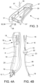
Figure 3 shows a view of a component of the system for carrying skis ofFigure 1 ; -
Figure 4A shows a detail view of the system for carrying skis ofFigure 1 , in the assembled configuration; -
Figure 4B shows a detail view of the system for carrying skis ofFigure 1 , in the partially disassembled configuration; -
Figure 5 shows a further view of a component of the system for carrying skis ofFigure 1 ; -
Figure 6A shows a top view of a further component of the system for carrying skis ofFigure 1 ; -
Figure 6B shows a perspective view of the component ofFigure 6A ; -
Figure 6C shows a further perspective view of the component ofFigure 6A ; -
Figure 6D shows a further perspective view of the component ofFigure 6A , in the partially assembled configuration; -
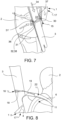
Figure 7 shows the system for carrying skis ofFigure 1 , in a first operating configuration; -
Figure 8 shows the system for carrying skis ofFigure 1 , in a second operating configuration. - With reference to the figures, a ski rack system is generally indicated with
reference numeral 1. - The system for carrying
skis 1 is adapted to be worn over the shoulders by a user, or anathlete 2, and is further configured for the transport of a pair ofskis 3 over the shoulders. - The system for carrying
skis 1 comprises aframe 4, afirst shoulder strap 5 and asecond shoulder strap 6. - The
first shoulder strap 5 and thesecond shoulder strap 6 are connected to theframe 4. - An
upper end 7 of thefirst shoulder strap 5 is connected to a firstupper portion 8 of theframe 4. - A
lower end 9 of thefirst shoulder strap 5 is connected to a firstlower portion 10 of theframe 4. - An
upper end 11 of thesecond shoulder strap 6 is connected to a secondupper portion 12 of theframe 4. - A
lower end 13 of thesecond shoulder strap 6 is connected to a secondlower portion 14 of theframe 4. - The system for carrying
skis 1 further comprises a lowerski rack support 15, positioned at the firstlower portion 10 of theframe 4. - The system for carrying
skis 1 further comprises an upperski rack support 16, positioned at thesecond shoulder strap 6. - According to an aspect of the invention, the upper
ski rack support 16 comprises ahook 18 elastically connected to thesecond shoulder strap 6 by means of anelastic return element 19. - Furthermore, a
covering 20 is connected to thesecond shoulder strap 6, so that the covering 20 and thesecond shoulder strap 6 delimit aguide duct 21 extending from theupper end 11 to thelower end 13 of thesecond shoulder strap 6, i.e., in the direction of the length of thesecond shoulder strap 6. - Furthermore, the
elastic return element 19 extends through theguide duct 21 formed by the covering 20 and thesecond shoulder strap 6. - Advantageously, thereby, the
elastic return element 19 and thehook 18 connected thereto are constrained to thesecond shoulder strap 6 and theelastic return element 19, connected to thehook 18, is therefore prevented from getting caught on the system for carryingskis 1 worn by theathlete 2. - With a further advantage, such configuration reduces the time required to couple the pair of
skis 3 to the system for carrying skis - According to a preferred embodiment, the
elastic return element 19 is configured as a cord, in particular a spiral cord. - According to the invention, a
contrast element 22 is integrally connected to the covering 20 and to thesecond shoulder strap 6, at theupper end 11 of thesecond shoulder strap 6. - The
contrast element 22 forms a central throughhole 23, through which theelastic return element 19 connected to thehook 18 extends. - In accordance with the invention, the
contrast element 22 and the central throughhole 23 are sized so that theelastic element 19 may slide inside the central throughhole 23, and thehook 18 may partially be inserted into the central throughhole 23 but cannot cross the central throughhole 23. - Advantageously, thereby, the
hook 18, when it is not in use or when it is not fixed to the pair ofskis 3, is elastically constrained so as to partially extend outside theguide duct 21, and therefore be readily available for theathlete 2 who intended to grab and handle it. - With a further advantage, when the
hook 18 is released from the connection to the pair ofskis 3, theelastic return element 19 returns thehook 18 towards thecontrast element 22, so that theelastic hook 18 is partially inserted into the central throughhole 23 and partially protrudes from theguide duct 21. - Therefore, the
elastic return element 19 independently repositions thehook 18, when released from the connection to the pair ofskis 3. - This considerably increases the speed and the convenience of handling and using the
ski rack system 1. - According to an embodiment, the
contrast element 22 forms afirst slot 24, for the passage of first connection means 27 for a connection between thecontrast element 22 and thecovering 20, and asecond slot 25 for the passage of second connection means 28 for a connection between thecontrast element 22 and thesecond shoulder strap 6. - Advantageously, the
first slot 24 and thesecond slot 25 ensure a firm and simple connection between thecontrast element 22 and the covering 20 and thesecond shoulder strap 6. - According to an embodiment, the
elastic return element 19 slides inside a tubular covering made of apolymeric material 26. - Advantageously, the
polymeric material 26 protects theelastic return element 19 from any damage and/or tearing. - As for the lower ski rack support 15, according to an embodiment of the invention, this comprises a rigid annular element.
- The rigid annular element forms an annular opening which defines a threading direction, for threading a lower portion of the pair of
skis 3 inside the rigid annular element. - The rigid annular element is further configured to vertically support the pair of
skis 3, and, in particular, to support the attachments of the pair ofskis 3. - Advantageously, the rigid annular element allows to insert a lower portion of the pair of
skis 3 inside the rigid annular element along a threading direction parallel to the length direction of the pair ofskis 3. - According to an alternative embodiment, the lower
ski rack support 15 comprises asupport element 30 in the shape of an open channel and having two ends 31, 31'. - The
support element 30 forms afirst opening 33 defining afirst insertion direction 34. - The two ends 31, 31' of the
support element 30 form asecond opening 35 defining asecond insertion direction 36 transversal to thefirst insertion direction 34. - The lower
ski rack support 15 further comprises a closing element 32. - The closing element 32 extends between the two ends 31, 31' of the
support element 30. - The closing element 32 may be moved between a closing position, in which the
second opening 35 closes, and an opening position, in which thesecond opening 35 opens. - Advantageously, a system for carrying
skis 1 thus configured ensures an easy, comfortable and less physically challenging support and fixing of a pair ofskis 3 to the system for carryingskis 1, and, in particular, with reference to the insertion, support and fixing of a lower portion of the pair ofskis 3. - In fact, the possibility of introducing the pair of
skis 3, and, in particular, the lower portion of the pair ofskis 3, through thesecond opening 35 along thesecond insertion direction 36, avoids having to lift the pair ofskis 3 to a height from the ground higher than that at which the lowerski rack support 15 is located. - Furthermore, with particular reference to competitive practice, such configuration of the system for carrying
skis 1 considerably reduces the time required to fix the pair ofskis 3 to theski rack system 1. - The
second insertion direction 36 is advantageously horizontal, therefore it allows to insert the pair ofskis 3, which extend in length along a length direction, inside the lowerski rack support 15 along a direction transversal to the direction of the extension in length of the pair ofskis 3, thus reducing the complexity, the effort and the time required to insert the pair ofskis 3 inside the lowerski rack support 15. - The
first insertion direction 34 is vertical, therefore it is still possible to insert the pair ofskis 3 into the lowerski rack support 15 also from top downwards. - The
support element 30 of the lowerski rack support 15 forms avertical support wall 37 configured to support the pair ofskis 3 vertically, and, in particular, to support the attachments of the pair ofskis 3. - According to an embodiment, the closing element 32 consists of a spring element 38.
- The spring element 38 is hinged to one of the two ends 31, 31' of the
support element 30, and is elastically biased against the other of the two ends 31, 31' of thesupport element 30, to a closing position, so as to close thesecond opening 35. - The spring element 38 is rotatable towards the interior of the lower
ski rack support 15, towards the opening position, so as to open thesecond opening 35. - Advantageously, by rotating towards the inside of the
second opening 35, the manual movement of the spring element 38 is avoided to open thesecond opening 35, which is instead opened exclusively by contact with the pair ofskis 3. Furthermore, after inserting the pair ofskis 3 inside the lowerski rack support 15, the spring element 38 automatically closes, locking the pair ofskis 3 inside the lowerski rack support 15. - According to an alternative embodiment, the spring element 38 is configured to rotate towards the outside of the lower
ski rack support 15. - According to an embodiment, when the system for carrying
skis 1 is worn by anathlete 2, thefirst shoulder strap 5 corresponds to a right shoulder strap and thesecond shoulder strap 6 corresponds to a left shoulder strap. - According to an alternative embodiment, the
first shoulder strap 5 corresponds to the left shoulder strap and thesecond shoulder strap 6 corresponds to the right shoulder strap. - According to a further aspect of the invention, a
ski backpack 17 comprises the system for carryingskis 1 described above. - The
ski backpack 17 has two shoulder straps which correspond, respectively, to thefirst shoulder strap 5 and to thesecond shoulder strap 6. - According to an embodiment, the
ski backpack 17 may comprise one or more housings or systems for containing and/or transporting one or more further ski mountaineering tools, such as, for example, a helmet, an ice ax, crampons, and other material useful to the sportsman or athlete. - According to a further aspect of the invention, a method for securing and supporting a pair of
skis 3, extending along a length direction, and having attachments, on the back of anathlete 2, comprises the following steps: - providing a system for carrying
skis 1 fitted with aframe 4, afirst shoulder strap 5, asecond shoulder strap 6, a lowerski rack support 15 and an upperski rack support 16; - wearing the system for carrying
skis 1 over the shoulders; - inserting a lower portion of the pair of
skis 3 into the lowerski rack support 15, wherein the insertion direction of the pair ofskis 3 into the lowerski rack support 15 is transversal to the length direction of the pair ofskis 3; - coupling the attachments of the pair of
skis 3 to the lowerski rack support 15, for vertically supporting the pair ofskis 3; - coupling an upper portion of the pair of
skis 3 to the upperski rack support 16. - According to an alternative embodiment, a method for securing and supporting a pair of
skis 3, extending along a length direction and having attachments, on the back of anathlete 2, comprises the following steps: - providing a system for carrying
skis 1 fitted with aframe 4, afirst shoulder strap 5, asecond shoulder strap 6, a lowerski rack support 15 and an upperski rack support 16; - wearing the system for carrying
skis 1 over the shoulders; - inserting a lower portion of the pair of
skis 3 into the lowerski rack support 15, wherein the insertion direction of the pair ofskis 3 into the lowerski rack support 15 is parallel to the length direction of the pair ofskis 3; - coupling the attachments of the pair of
skis 3 to the lowerski rack support 15, for vertically supporting the pair ofskis 3; - coupling an upper portion of the pair of
skis 3 to the upperski rack support 16. - According to a further aspect of the invention, a method for securing and supporting a pair of
skis 3, extending along a length direction, and having attachments, on the back of anathlete 2, comprises the following steps: - providing a
ski backpack 17 equipped with a system for carryingskis 1 fitted with aframe 4, afirst shoulder strap 5, asecond shoulder strap 6, a lowerski rack support 15 and an upperski rack support 16; - wearing the
ski backpack 17 over the shoulders; - inserting a lower portion of the pair of
skis 3 into the lowerski rack support 15, wherein the insertion direction of the pair ofskis 3 into the lowerski rack support 15 is transversal to the length direction of the pair ofskis 3; - coupling the attachments of the pair of
skis 3 to the lowerski rack support 15, for vertically supporting the pair ofskis 3; - coupling an upper portion of the pair of
skis 3 to the upperski rack support 16. - According to an alternative embodiment, a method for securing and supporting a pair of
skis 3, extending along a length direction and having attachments, on the back of anathlete 2, comprises the following steps: - providing a
ski backpack 17 equipped with aski rack system 1 fitted with aframe 4, afirst shoulder strap 5, asecond shoulder strap 6, a lowerski rack support 15 and an upperski rack support 16; - wearing the system for carrying
skis 1 over the shoulders; - inserting a lower portion of the pair of
skis 3 into the lowerski rack support 15, wherein the insertion direction of the pair ofskis 3 into the lowerski rack support 15 is parallel to the length direction of the pair ofskis 3; - coupling the attachments of the pair of
skis 3 to the lowerski rack support 15, for vertically supporting the pair ofskis 3; - coupling an upper portion of the pair of
skis 3 to the upperski rack support 16. - Naturally, those skilled in the art will be able to make modifications or adaptations to the present invention, without however departing from the scope of the claims below.
Claims (20)
- A system for carrying skis (1), adapted to be worn over the shoulder by an athlete (2), and configured to transport, over the shoulder, a pair of skis (3), said system for carrying skis (1) comprising:- a frame (4);- a first shoulder strap (5) and a second shoulder strap (6), connected to the frame (4);wherein an upper end (7) of the first shoulder strap (5) is connected to a first upper portion (8) of the frame (4), and a lower end (9) of the first shoulder strap (5) is connected to a first lower portion (10) of the frame (4); wherein an upper end (11) of the second shoulder strap (6) is connected to a second upper portion (12) of the frame (4), and a lower end (13) of the second shoulder strap (6) is connected to a second lower portion (14) of the frame (4) ;- a lower ski support (15), positioned at the first lower portion (10) of the frame (4);- an upper ski support (16), positioned at the second shoulder strap (6);wherein the upper ski support (16) comprises a hook (18) elastically connected to the second shoulder strap (6) by means of an elastic return element (19),and wherein a covering (20) is connected to the second shoulder strap (6), so that the covering (20) and the second shoulder strap (6) delimit a guide duct (21) extending from the upper end (11) to the lower end (13) of the second shoulder strap (6),and wherein the elastic return element (19) extends through the guide duct (21) formed by the covering (20) and the second shoulder strap (6),and characterised in that,a contrast element (22) is integrally connected to the covering (20) and to the second shoulder strap (6), at the upper end (11) of the second shoulder strap (6), wherein the contrast element (22) forms a central through hole (23),wherein the elastic return element (19), connected to the hook (18), extends through the central through hole (23),and wherein the contrast element (22) and the central through hole (23) are sized so that the elastic element (19) can slide inside the central through hole (23), and the hook (18) can partially be inserted into the central through hole (23) but cannot cross the central through hole (23).
- A system for carrying skis (1) according to the claim 1, wherein the lower ski support (15) comprises:- a support element (30) in the shape of an open channel, and having two ends (31, 31');- a closing element (32);wherein the support element (30) forms a first opening (33) defining a first insertion direction (34),wherein the two ends (31, 31') of the support element (30) form a second opening (35) defining a second insertion direction (36) transversal to the first insertion direction (34);wherein the closing element (32) extends between the two ends (31, 31') of the support element (30), said closing element (32) being movable between a closing position, in which it closes the second opening (35), and an opening position, in which it opens the second opening (35).
- A system for carrying skis (1) according to claim 2, wherein the support element (30) of the lower ski support (15) forms a vertical support wall (37) configured to support the pair of skis (3) vertically.
- A system for carrying skis (1) according to claim 2 or 3, wherein the closing element (32) consists of a spring element (38).
- A system for carrying skis(1) according to claim 4, wherein the spring element (38) is hinged to one of the two ends (31, 31') of the support element (30) and elastically biased against the other of the two ends (31, 31') of the support element (30) to a closing position, so as to close the second opening (35).
- A system for carrying skis (1) according to claim 5, wherein the spring element (38) is rotatable towards the interior of the lower ski support (15), towards the opening position, so as to open the second opening (35).
- A system for carrying skis (1) according to claim 6, wherein the contrast element (22) forms a first slot (24) for the passage of first connection means (27) for a connection between the contrast element (22) and the covering (20), and a second slot (25) for the passage of second connection means (28) for a connection between the contrast element (22) and the second shoulder strap (6).
- A system for carrying skis (1) according to any one of the preceding claims, wherein the elastic return element (19) slides inside a tubular covering (26) made of a polymeric material.
- A system for carrying skis (1) according to any one of the preceding claims, wherein the lower ski support (15) comprises a rigid annular element forming an annular opening which defines a threading direction, for threading a lower portion of the pair of skis (3) into the rigid annular element.
- A system for carrying skis according to any one of the claims from 1 to 8, wherein the lower ski support (15) comprises:- a support element (30) in the shape of an open channel, and having two ends (31, 31');- a closing element (32);wherein the support element (30) forms a first opening (33) defining a first insertion direction (34),wherein the two ends (31, 31') of the support element (30) form a second opening (35) defining a second insertion direction (36) transversal to the first insertion direction (34);wherein the closing element (32) extends between the two ends (31, 31') of the support element (30), said closing element (32) being movable between a closing position, in which it closes the second opening (35), and an opening position, in which it opens the second opening(35).
- A system for carrying skis (1) according to claim 10, wherein the support element (30) of the lower ski support (15) forms a vertical support wall (37) configured to support the pair of skis (3) vertically.
- A system for carrying skis (1) according to claim 10 or 11, wherein the closing element (32) consists of a spring element (38).
- A system for carrying skis (1) according to claim 12, wherein the spring element (38) is hinged to one of the two ends (31, 31') of the support element (30) and elastically biased against the other of the two ends (31, 31') of the support element (30) to a closing position, so as to close the second opening (35).
- A system for carrying skis (1) according to claim 13, wherein the spring element (38) is rotatable towards the interior of the lower ski support (15), towards the opening position, so as to open the second opening (35).
- A backpack (17), comprising the system for carrying skis (1) according to any one of the claims from 1 to 14.
- A backpack (17) according to the preceding claim, comprising one or more housings or systems for containing and/or transporting one or more further tools of ski mountaineering.
- A method for securing and supporting a pair of skis (3) extending along a length direction and having attachments, on the back of an athlete (2), comprises the following steps:- providing a system for carrying skis (1) fitted with a frame (4), a first shoulder strap (5), a second shoulder strap (6), a lower ski support (15) and an upper ski support (16) according to claims 1 and 10;- wearing the system for carrying skis (1) over the shoulders;- inserting a lower portion of the pair of skis (3) into the lower ski support (15), wherein the insertion direction of the pair of skis (3) into the lower ski support (15) is transversal to the length direction of the pair of skis (3);- coupling the attachments of the pair of skis (3) to the lower ski support (15), for vertically supporting the pair of skis (3);- coupling an upper portion of the pair of skis (3) to the upper ski support (16).
- A method for securing and supporting a pair of skis (3) extending along a length direction and having attachments, on the back of an athlete (2), comprises the following steps:- providing a system for carrying skis (1) fitted with a frame (4), a first shoulder strap (5), a second shoulder strap (6), a lower ski support (15) and an upper ski support (16) according to claims 1 and 9;- wearing the system for carrying skis (1) over the shoulders;- inserting a lower portion of the pair of skis (3) into the lower ski support (15), wherein the insertion direction of the pair of skis (3) into the lower ski support (15) is parallel to the length direction of the pair of skis (3);- coupling the attachments of the pair of skis (3) to the lower ski support (15), for vertically supporting the pair of skis (3);- coupling an upper portion of the pair of skis (3) to the upper ski support (16).
- A method for securing and supporting a pair of skis (3), extending along a length direction and having attachments, on the back of an athlete (2), comprises the following steps:- providing a ski backpack (17) equipped with a system for carrying skis (1) fitted with a frame (4), a first shoulder strap (5), a second shoulder strap (6), a lower ski support (15) and an upper ski support (16) according to claims 1, 10 and 15;- wearing the ski backpack (17) over the shoulders;- inserting a lower portion of the pair of skis (3) into the lower ski support (15), wherein the insertion direction of the pair of skis (3) into the lower ski support (15) is transversal to the length direction of the pair of skis (3);- coupling the attachments of the pair of skis (3) to the lower ski support (15), for vertically supporting the pair of skis (3);- coupling an upper portion of the pair of skis (3) to the upper ski support (16).
- A method for securing and supporting a pair of skis (3), extending along a length direction and having attachments, on the back of an athlete (2), comprises the following steps:- providing a ski backpack (17) equipped with a system for carrying skis (1) fitted with a frame (4), a first shoulder strap (5), a second shoulder strap (6), a lower ski support (15) and an upper ski support (16) according to claims 1, 9 and 15;- wearing the ski backpack (17) over the shoulders;- inserting a lower portion of the pair of skis (3) into the lower ski support (15), wherein the insertion direction of the pair of skis (3) into the lower ski support (15) is parallel to the length direction of the pair of skis (3);- coupling the attachments of the pair of skis (3) to the lower ski support (15), for vertically supporting the pair of skis (3);- coupling an upper portion of the pair of skis (3) to the upper ski support (16).
Applications Claiming Priority (1)
| Application Number | Priority Date | Filing Date | Title |
|---|---|---|---|
| IT102019000024466A IT201900024466A1 (en) | 2019-12-18 | 2019-12-18 | SKI RACK SYSTEM |
Publications (2)
| Publication Number | Publication Date |
|---|---|
| EP3838063A1 EP3838063A1 (en) | 2021-06-23 |
| EP3838063B1 true EP3838063B1 (en) | 2024-12-18 |
Family
ID=70295605
Family Applications (1)
| Application Number | Title | Priority Date | Filing Date |
|---|---|---|---|
| EP20215343.3A Active EP3838063B1 (en) | 2019-12-18 | 2020-12-18 | Ski rack system |
Country Status (2)
| Country | Link |
|---|---|
| EP (1) | EP3838063B1 (en) |
| IT (1) | IT201900024466A1 (en) |
Citations (1)
| Publication number | Priority date | Publication date | Assignee | Title |
|---|---|---|---|---|
| DE202009001165U1 (en) * | 2009-01-30 | 2009-04-09 | Salewa Sport Ag | Ski vest, ski equipment element and clothing / equipment part |
Family Cites Families (3)
| Publication number | Priority date | Publication date | Assignee | Title |
|---|---|---|---|---|
| FR2947701B1 (en) * | 2009-07-10 | 2011-09-09 | Salomon Sas | BACKPACK |
| US20110180575A1 (en) * | 2010-01-27 | 2011-07-28 | David Eric Abramowitz | Snow sport bag |
| US9907369B2 (en) * | 2015-01-20 | 2018-03-06 | Thule Ip Ab | Adjustable carrying pack |
-
2019
- 2019-12-18 IT IT102019000024466A patent/IT201900024466A1/en unknown
-
2020
- 2020-12-18 EP EP20215343.3A patent/EP3838063B1/en active Active
Patent Citations (1)
| Publication number | Priority date | Publication date | Assignee | Title |
|---|---|---|---|---|
| DE202009001165U1 (en) * | 2009-01-30 | 2009-04-09 | Salewa Sport Ag | Ski vest, ski equipment element and clothing / equipment part |
Also Published As
| Publication number | Publication date |
|---|---|
| IT201900024466A1 (en) | 2021-06-18 |
| EP3838063A1 (en) | 2021-06-23 |
Similar Documents
| Publication | Publication Date | Title |
|---|---|---|
| US5762242A (en) | Ski carrying system | |
| US6010051A (en) | Apparatus for releasably carrying recreational equipment | |
| US9872553B1 (en) | Support system and carrying case for optical instrument | |
| US9650063B2 (en) | Detachable assembly | |
| US10493355B2 (en) | Carrying ski equipment | |
| EP3047754B1 (en) | Adjustable carrying pack | |
| US20110006090A1 (en) | Backpack | |
| US10299576B2 (en) | Strap for retaining articles | |
| WO2011094220A1 (en) | Snow sport bag | |
| ITMI20061930A1 (en) | BACKPACK WITH SLIDING SIDE MODULE | |
| EP3838063A1 (en) | Ski rack system | |
| US20090159629A1 (en) | Rucksack which may be switched to a front position | |
| EP2802391B1 (en) | A hand strap for a skiing pole or similar | |
| EP3782506B1 (en) | System of self-adjusting straps of a backpack, suitcase or briefcase | |
| US12172069B2 (en) | Accessory holder for attaching an accessory to a surface | |
| US11330924B2 (en) | Device and method for aiding putting on a ski boot | |
| US10064479B2 (en) | Scabbard holder for a hand saw | |
| CA2928079C (en) | Pole climbing fall restriction assembly | |
| US9610485B2 (en) | Golf bag clamping apparatus | |
| EP3892342A1 (en) | Transport device | |
| US20130284784A1 (en) | Mountain Tool Holster | |
| EP2594150A1 (en) | Umbrella for holding a golf club | |
| US20090199532A1 (en) | Fruit harvesting belt and bucket system | |
| CA1238611A (en) | Ski carrier strap | |
| WO2016075247A1 (en) | Backpack |
Legal Events
| Date | Code | Title | Description |
|---|---|---|---|
| PUAI | Public reference made under article 153(3) epc to a published international application that has entered the european phase |
Free format text: ORIGINAL CODE: 0009012 |
|
| STAA | Information on the status of an ep patent application or granted ep patent |
Free format text: STATUS: THE APPLICATION HAS BEEN PUBLISHED |
|
| AK | Designated contracting states |
Kind code of ref document: A1 Designated state(s): AL AT BE BG CH CY CZ DE DK EE ES FI FR GB GR HR HU IE IS IT LI LT LU LV MC MK MT NL NO PL PT RO RS SE SI SK SM TR |
|
| STAA | Information on the status of an ep patent application or granted ep patent |
Free format text: STATUS: REQUEST FOR EXAMINATION WAS MADE |
|
| 17P | Request for examination filed |
Effective date: 20211027 |
|
| RBV | Designated contracting states (corrected) |
Designated state(s): AL AT BE BG CH CY CZ DE DK EE ES FI FR GB GR HR HU IE IS IT LI LT LU LV MC MK MT NL NO PL PT RO RS SE SI SK SM TR |
|
| GRAP | Despatch of communication of intention to grant a patent |
Free format text: ORIGINAL CODE: EPIDOSNIGR1 |
|
| STAA | Information on the status of an ep patent application or granted ep patent |
Free format text: STATUS: GRANT OF PATENT IS INTENDED |
|
| INTG | Intention to grant announced |
Effective date: 20240723 |
|
| GRAS | Grant fee paid |
Free format text: ORIGINAL CODE: EPIDOSNIGR3 |
|
| GRAA | (expected) grant |
Free format text: ORIGINAL CODE: 0009210 |
|
| STAA | Information on the status of an ep patent application or granted ep patent |
Free format text: STATUS: THE PATENT HAS BEEN GRANTED |
|
| AK | Designated contracting states |
Kind code of ref document: B1 Designated state(s): AL AT BE BG CH CY CZ DE DK EE ES FI FR GB GR HR HU IE IS IT LI LT LU LV MC MK MT NL NO PL PT RO RS SE SI SK SM TR |
|
| REG | Reference to a national code |
Ref country code: CH Ref legal event code: EP |
|
| REG | Reference to a national code |
Ref country code: DE Ref legal event code: R096 Ref document number: 602020043279 Country of ref document: DE |
|
| REG | Reference to a national code |
Ref country code: IE Ref legal event code: FG4D |
|
| REG | Reference to a national code |
Ref country code: LT Ref legal event code: MG9D |
|
| PG25 | Lapsed in a contracting state [announced via postgrant information from national office to epo] |
Ref country code: HR Free format text: LAPSE BECAUSE OF FAILURE TO SUBMIT A TRANSLATION OF THE DESCRIPTION OR TO PAY THE FEE WITHIN THE PRESCRIBED TIME-LIMIT Effective date: 20241218 |
|
| PG25 | Lapsed in a contracting state [announced via postgrant information from national office to epo] |
Ref country code: FI Free format text: LAPSE BECAUSE OF FAILURE TO SUBMIT A TRANSLATION OF THE DESCRIPTION OR TO PAY THE FEE WITHIN THE PRESCRIBED TIME-LIMIT Effective date: 20241218 |
|
| PG25 | Lapsed in a contracting state [announced via postgrant information from national office to epo] |
Ref country code: BG Free format text: LAPSE BECAUSE OF FAILURE TO SUBMIT A TRANSLATION OF THE DESCRIPTION OR TO PAY THE FEE WITHIN THE PRESCRIBED TIME-LIMIT Effective date: 20241218 |
|
| PG25 | Lapsed in a contracting state [announced via postgrant information from national office to epo] |
Ref country code: NO Free format text: LAPSE BECAUSE OF FAILURE TO SUBMIT A TRANSLATION OF THE DESCRIPTION OR TO PAY THE FEE WITHIN THE PRESCRIBED TIME-LIMIT Effective date: 20250318 |
|
| REG | Reference to a national code |
Ref country code: NL Ref legal event code: MP Effective date: 20241218 |
|
| PG25 | Lapsed in a contracting state [announced via postgrant information from national office to epo] |
Ref country code: LV Free format text: LAPSE BECAUSE OF FAILURE TO SUBMIT A TRANSLATION OF THE DESCRIPTION OR TO PAY THE FEE WITHIN THE PRESCRIBED TIME-LIMIT Effective date: 20241218 Ref country code: GR Free format text: LAPSE BECAUSE OF FAILURE TO SUBMIT A TRANSLATION OF THE DESCRIPTION OR TO PAY THE FEE WITHIN THE PRESCRIBED TIME-LIMIT Effective date: 20250319 |
|
| PG25 | Lapsed in a contracting state [announced via postgrant information from national office to epo] |
Ref country code: RS Free format text: LAPSE BECAUSE OF FAILURE TO SUBMIT A TRANSLATION OF THE DESCRIPTION OR TO PAY THE FEE WITHIN THE PRESCRIBED TIME-LIMIT Effective date: 20250318 |
|
| PG25 | Lapsed in a contracting state [announced via postgrant information from national office to epo] |
Ref country code: NL Free format text: LAPSE BECAUSE OF FAILURE TO SUBMIT A TRANSLATION OF THE DESCRIPTION OR TO PAY THE FEE WITHIN THE PRESCRIBED TIME-LIMIT Effective date: 20241218 |
|
| REG | Reference to a national code |
Ref country code: AT Ref legal event code: MK05 Ref document number: 1751490 Country of ref document: AT Kind code of ref document: T Effective date: 20241218 |
|
| PG25 | Lapsed in a contracting state [announced via postgrant information from national office to epo] |
Ref country code: SM Free format text: LAPSE BECAUSE OF FAILURE TO SUBMIT A TRANSLATION OF THE DESCRIPTION OR TO PAY THE FEE WITHIN THE PRESCRIBED TIME-LIMIT Effective date: 20241218 |
|
| PG25 | Lapsed in a contracting state [announced via postgrant information from national office to epo] |
Ref country code: PL Free format text: LAPSE BECAUSE OF FAILURE TO SUBMIT A TRANSLATION OF THE DESCRIPTION OR TO PAY THE FEE WITHIN THE PRESCRIBED TIME-LIMIT Effective date: 20241218 |
|
| PG25 | Lapsed in a contracting state [announced via postgrant information from national office to epo] |
Ref country code: ES Free format text: LAPSE BECAUSE OF FAILURE TO SUBMIT A TRANSLATION OF THE DESCRIPTION OR TO PAY THE FEE WITHIN THE PRESCRIBED TIME-LIMIT Effective date: 20241218 |
|
| PG25 | Lapsed in a contracting state [announced via postgrant information from national office to epo] |
Ref country code: IS Free format text: LAPSE BECAUSE OF FAILURE TO SUBMIT A TRANSLATION OF THE DESCRIPTION OR TO PAY THE FEE WITHIN THE PRESCRIBED TIME-LIMIT Effective date: 20250418 |
|
| PG25 | Lapsed in a contracting state [announced via postgrant information from national office to epo] |
Ref country code: PT Free format text: LAPSE BECAUSE OF FAILURE TO SUBMIT A TRANSLATION OF THE DESCRIPTION OR TO PAY THE FEE WITHIN THE PRESCRIBED TIME-LIMIT Effective date: 20250421 |
|
| PG25 | Lapsed in a contracting state [announced via postgrant information from national office to epo] |
Ref country code: EE Free format text: LAPSE BECAUSE OF FAILURE TO SUBMIT A TRANSLATION OF THE DESCRIPTION OR TO PAY THE FEE WITHIN THE PRESCRIBED TIME-LIMIT Effective date: 20241218 |
|
| PG25 | Lapsed in a contracting state [announced via postgrant information from national office to epo] |
Ref country code: AT Free format text: LAPSE BECAUSE OF FAILURE TO SUBMIT A TRANSLATION OF THE DESCRIPTION OR TO PAY THE FEE WITHIN THE PRESCRIBED TIME-LIMIT Effective date: 20241218 Ref country code: RO Free format text: LAPSE BECAUSE OF FAILURE TO SUBMIT A TRANSLATION OF THE DESCRIPTION OR TO PAY THE FEE WITHIN THE PRESCRIBED TIME-LIMIT Effective date: 20241218 |
|
| PG25 | Lapsed in a contracting state [announced via postgrant information from national office to epo] |
Ref country code: SK Free format text: LAPSE BECAUSE OF FAILURE TO SUBMIT A TRANSLATION OF THE DESCRIPTION OR TO PAY THE FEE WITHIN THE PRESCRIBED TIME-LIMIT Effective date: 20241218 |
|
| PG25 | Lapsed in a contracting state [announced via postgrant information from national office to epo] |
Ref country code: CZ Free format text: LAPSE BECAUSE OF FAILURE TO SUBMIT A TRANSLATION OF THE DESCRIPTION OR TO PAY THE FEE WITHIN THE PRESCRIBED TIME-LIMIT Effective date: 20241218 |
|
| REG | Reference to a national code |
Ref country code: CH Ref legal event code: PL |
|
| PG25 | Lapsed in a contracting state [announced via postgrant information from national office to epo] |
Ref country code: LU Free format text: LAPSE BECAUSE OF NON-PAYMENT OF DUE FEES Effective date: 20241218 |
|
| PG25 | Lapsed in a contracting state [announced via postgrant information from national office to epo] |
Ref country code: SE Free format text: LAPSE BECAUSE OF FAILURE TO SUBMIT A TRANSLATION OF THE DESCRIPTION OR TO PAY THE FEE WITHIN THE PRESCRIBED TIME-LIMIT Effective date: 20241218 |
|
| PG25 | Lapsed in a contracting state [announced via postgrant information from national office to epo] |
Ref country code: MC Free format text: LAPSE BECAUSE OF FAILURE TO SUBMIT A TRANSLATION OF THE DESCRIPTION OR TO PAY THE FEE WITHIN THE PRESCRIBED TIME-LIMIT Effective date: 20241218 |
|
| REG | Reference to a national code |
Ref country code: DE Ref legal event code: R097 Ref document number: 602020043279 Country of ref document: DE |
|
| REG | Reference to a national code |
Ref country code: BE Ref legal event code: MM Effective date: 20241231 |
|
| PG25 | Lapsed in a contracting state [announced via postgrant information from national office to epo] |
Ref country code: DK Free format text: LAPSE BECAUSE OF FAILURE TO SUBMIT A TRANSLATION OF THE DESCRIPTION OR TO PAY THE FEE WITHIN THE PRESCRIBED TIME-LIMIT Effective date: 20241218 |
|
| PG25 | Lapsed in a contracting state [announced via postgrant information from national office to epo] |
Ref country code: BE Free format text: LAPSE BECAUSE OF NON-PAYMENT OF DUE FEES Effective date: 20241231 |
|
| PG25 | Lapsed in a contracting state [announced via postgrant information from national office to epo] |
Ref country code: CH Free format text: LAPSE BECAUSE OF NON-PAYMENT OF DUE FEES Effective date: 20241231 |
|
| PG25 | Lapsed in a contracting state [announced via postgrant information from national office to epo] |
Ref country code: IE Free format text: LAPSE BECAUSE OF NON-PAYMENT OF DUE FEES Effective date: 20241218 |
|
| PLBE | No opposition filed within time limit |
Free format text: ORIGINAL CODE: 0009261 |
|
| STAA | Information on the status of an ep patent application or granted ep patent |
Free format text: STATUS: NO OPPOSITION FILED WITHIN TIME LIMIT |
|
| 26N | No opposition filed |
Effective date: 20250919 |
|
| GBPC | Gb: european patent ceased through non-payment of renewal fee |
Effective date: 20250318 |
|
| PG25 | Lapsed in a contracting state [announced via postgrant information from national office to epo] |
Ref country code: GB Free format text: LAPSE BECAUSE OF NON-PAYMENT OF DUE FEES Effective date: 20250318 |
|
| PGFP | Annual fee paid to national office [announced via postgrant information from national office to epo] |
Ref country code: IT Payment date: 20251007 Year of fee payment: 6 |
|
| PGFP | Annual fee paid to national office [announced via postgrant information from national office to epo] |
Ref country code: FR Payment date: 20251128 Year of fee payment: 6 |
|
| PGFP | Annual fee paid to national office [announced via postgrant information from national office to epo] |
Ref country code: DE Payment date: 20251222 Year of fee payment: 6 |
|
| PG25 | Lapsed in a contracting state [announced via postgrant information from national office to epo] |
Ref country code: CY Free format text: LAPSE BECAUSE OF FAILURE TO SUBMIT A TRANSLATION OF THE DESCRIPTION OR TO PAY THE FEE WITHIN THE PRESCRIBED TIME-LIMIT Effective date: 20241218 |