EP3837536B1 - Apparatus for the measurement of mineral slurries - Google Patents
Apparatus for the measurement of mineral slurries Download PDFInfo
- Publication number
- EP3837536B1 EP3837536B1 EP19849813.1A EP19849813A EP3837536B1 EP 3837536 B1 EP3837536 B1 EP 3837536B1 EP 19849813 A EP19849813 A EP 19849813A EP 3837536 B1 EP3837536 B1 EP 3837536B1
- Authority
- EP
- European Patent Office
- Prior art keywords
- measurement probe
- ray
- mount
- probe
- rays
- Prior art date
- Legal status (The legal status is an assumption and is not a legal conclusion. Google has not performed a legal analysis and makes no representation as to the accuracy of the status listed.)
- Active
Links
Images
Classifications
-
- G—PHYSICS
- G01—MEASURING; TESTING
- G01N—INVESTIGATING OR ANALYSING MATERIALS BY DETERMINING THEIR CHEMICAL OR PHYSICAL PROPERTIES
- G01N23/00—Investigating or analysing materials by the use of wave or particle radiation, e.g. X-rays or neutrons, not covered by groups G01N3/00 – G01N17/00, G01N21/00 or G01N22/00
- G01N23/22—Investigating or analysing materials by the use of wave or particle radiation, e.g. X-rays or neutrons, not covered by groups G01N3/00 – G01N17/00, G01N21/00 or G01N22/00 by measuring secondary emission from the material
- G01N23/223—Investigating or analysing materials by the use of wave or particle radiation, e.g. X-rays or neutrons, not covered by groups G01N3/00 – G01N17/00, G01N21/00 or G01N22/00 by measuring secondary emission from the material by irradiating the sample with X-rays or gamma-rays and by measuring X-ray fluorescence
-
- G—PHYSICS
- G01—MEASURING; TESTING
- G01N—INVESTIGATING OR ANALYSING MATERIALS BY DETERMINING THEIR CHEMICAL OR PHYSICAL PROPERTIES
- G01N33/00—Investigating or analysing materials by specific methods not covered by groups G01N1/00 - G01N31/00
- G01N33/24—Earth materials
-
- G—PHYSICS
- G01—MEASURING; TESTING
- G01N—INVESTIGATING OR ANALYSING MATERIALS BY DETERMINING THEIR CHEMICAL OR PHYSICAL PROPERTIES
- G01N2223/00—Investigating materials by wave or particle radiation
- G01N2223/07—Investigating materials by wave or particle radiation secondary emission
- G01N2223/076—X-ray fluorescence
-
- G—PHYSICS
- G01—MEASURING; TESTING
- G01N—INVESTIGATING OR ANALYSING MATERIALS BY DETERMINING THEIR CHEMICAL OR PHYSICAL PROPERTIES
- G01N2223/00—Investigating materials by wave or particle radiation
- G01N2223/30—Accessories, mechanical or electrical features
- G01N2223/308—Accessories, mechanical or electrical features support of radiation source
-
- G—PHYSICS
- G01—MEASURING; TESTING
- G01N—INVESTIGATING OR ANALYSING MATERIALS BY DETERMINING THEIR CHEMICAL OR PHYSICAL PROPERTIES
- G01N2223/00—Investigating materials by wave or particle radiation
- G01N2223/30—Accessories, mechanical or electrical features
- G01N2223/313—Accessories, mechanical or electrical features filters, rotating filter disc
-
- G—PHYSICS
- G01—MEASURING; TESTING
- G01N—INVESTIGATING OR ANALYSING MATERIALS BY DETERMINING THEIR CHEMICAL OR PHYSICAL PROPERTIES
- G01N2223/00—Investigating materials by wave or particle radiation
- G01N2223/30—Accessories, mechanical or electrical features
- G01N2223/316—Accessories, mechanical or electrical features collimators
-
- G—PHYSICS
- G01—MEASURING; TESTING
- G01N—INVESTIGATING OR ANALYSING MATERIALS BY DETERMINING THEIR CHEMICAL OR PHYSICAL PROPERTIES
- G01N2223/00—Investigating materials by wave or particle radiation
- G01N2223/30—Accessories, mechanical or electrical features
- G01N2223/317—Accessories, mechanical or electrical features windows
-
- G—PHYSICS
- G01—MEASURING; TESTING
- G01N—INVESTIGATING OR ANALYSING MATERIALS BY DETERMINING THEIR CHEMICAL OR PHYSICAL PROPERTIES
- G01N2223/00—Investigating materials by wave or particle radiation
- G01N2223/50—Detectors
- G01N2223/507—Detectors secondary-emission detector
-
- G—PHYSICS
- G01—MEASURING; TESTING
- G01N—INVESTIGATING OR ANALYSING MATERIALS BY DETERMINING THEIR CHEMICAL OR PHYSICAL PROPERTIES
- G01N2223/00—Investigating materials by wave or particle radiation
- G01N2223/60—Specific applications or type of materials
- G01N2223/616—Specific applications or type of materials earth materials
-
- G—PHYSICS
- G01—MEASURING; TESTING
- G01N—INVESTIGATING OR ANALYSING MATERIALS BY DETERMINING THEIR CHEMICAL OR PHYSICAL PROPERTIES
- G01N2223/00—Investigating materials by wave or particle radiation
- G01N2223/60—Specific applications or type of materials
- G01N2223/628—Specific applications or type of materials tubes, pipes
-
- G—PHYSICS
- G01—MEASURING; TESTING
- G01N—INVESTIGATING OR ANALYSING MATERIALS BY DETERMINING THEIR CHEMICAL OR PHYSICAL PROPERTIES
- G01N2223/00—Investigating materials by wave or particle radiation
- G01N2223/60—Specific applications or type of materials
- G01N2223/639—Specific applications or type of materials material in a container
Definitions
- the present disclosure relates to an apparatus for measuring elements within a mineral slurry.
- the present disclosure relates to an analyser for measuring elements within a mineral slurry by utilising X-ray fluorescence (XRF).
- XRF X-ray fluorescence
- Ores are extracted from the earth through mining and the ores are then processed, using mineral processing, to separate commercially valuable minerals from their respective ores.
- Mineral processing may involve a number of different sequential steps to identify and separate various minerals from raw material extracted from a mine. Such steps depend on the particular mineral to be extracted and the mining operation, but may include, for example, crushing, vibrating, flotation, and the like.
- the waste product is known as tailings. It is important to identify the amount of elements remaining in the slurry tailings, so that the efficiency of the mineral processing can be assessed.
- US5982847 discloses an X-ray fluorescence spectrometer for real-time wear metal analysis of lubricating oils.
- the present disclosure relates to an analyser for the measurement of elements in a mineral slurry using XRF.
- a first aspect of the present disclosure provides a measurement probe as defined in the claims appended hereto.
- a second aspect of the present disclosure provides an analyser for measurement of elements in a mineral slurry as defined in the claims appended hereto.
- the present disclosure provides an apparatus suitable for use in measuring elements in a mineral slurry by utilising X-ray fluorescence (XRF) analysis.
- the apparatus of the present disclosure is an analyser that is adapted to be positioned on a pipe containing a slurry, such that an X-ray source of the analyser is directed through an X-ray window of the analyser to be incident on the slurry within the pipe.
- An X-ray detector of the analyser detects scattered and emitted X-rays and the analyser processes data derived from the detected X-rays to determine the quantity of one or more elements of interest in the mineral slurry.
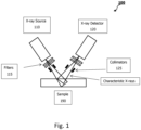
- Fig. 1 is a schematic representation of an X-ray fluorescence (XRF) apparatus 100.
- the XRF apparatus 100 includes an X-ray source 110 that is used to generate X-rays, which are a form of electromagnetic radiation. X-rays typically have a wavelength ranging from 0.01 to 10 nanometres and energies in the range 100 eV to 100 keV.
- the X-ray source 110 is positioned relative to a sample 190, such that X-rays emitted from the X-ray source 110 are incidence on the sample 190.
- the XRF apparatus includes filters 115, which are positioned between the X-ray source 110 and the sample 190 so as to attenuate X-rays emitted from the X-ray source 110. Filtering the X-rays may be used to filter out X-rays that are not of the appropriate wavelength and/or energy for the element(s) in the sample to be studied.
- the XRF apparatus 100 also includes an X-ray detector 120, which is adapted to receive and detect X-rays scattered from or emitted from the sample 190.
- the XRF apparatus 100 includes collimators 125, which restrict X-rays emitted from the X-ray source 110 so that those emitted source X-rays are directed towards the sample 190, and also restricts X-rays from the sample 190 so that those emitted sample X-rays are directed towards the X-ray detector 120.
- the X-ray source 110 emits X-rays directed at the sample 190.
- the incident X-ray may be absorbed by an electron in an atom of the sample 190. If the electron is ejected during this process (known as the photoelectric effect), then a vacancy is created in an atomic orbital. When this vacancy in the atomic orbital is filled, via the transition of a higher orbital electron, the excess energy may be emitted as a characteristic X-ray whose energy is the difference between the corresponding atomic orbitals. Since each element has a unique set of orbitals, then the characteristic X-rays are unique for each element.
- the emitted characteristic X-rays are then received by the X-ray detector 120, which may be implemented using an Energy Dispersive detector.
- a Silicon Drift Detector SDD is particularly suitable for such an analyser.
- the process of measuring the emissions of characteristic X-rays and determining the elemental abundances is typically called XRF analysis.
- the XRF apparatus 100 includes collimators 125 and filters 115, which may be used to condition the X-rays impinging on the sample 190 and the X-ray detector 120. Differing combinations of X-ray sources 110, filters 115, collimators 125, samples 190, and X-ray detectors 120 are widely used in a variety of modern day commercial XRF instrumentation.
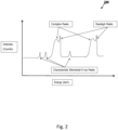
- Fig. 2 shows a simplified X-ray spectrum 200 measured by an Energy Dispersive X-ray detector.
- the spectrum 200 consists of one or more characteristic X-ray peaks from the elements present in the sample, and additionally one or more Compton and Rayleigh peaks due the scattering of X-rays in the sample.
- the heights of the characteristic X-ray peaks are related to their corresponding elemental abundances, whereas the Compton and Rayleigh peaks are more complexly related to the overall slurry composition.
- XRF analysis techniques are particularly suitable for deployment in the mining industry, where timely characterisation of the elemental composition of a mineral slurry may result in vastly improved economics.
- a mineral concentrator is where mineral bearing ore is processed. As part of this process, mined ore is crushed and milled, and water and chemicals are added to produce a slurry. The mineral bearing slurry is then processed via a variety of techniques, including flotation and gravity concentration, to produce a high grade slurry "concentrate", which is recovered. The waste slurry "tailings" typically exit the plant and are discarded. Timely characterisation of the slurry, via X-ray techniques, can yield much information regarding the operational state of the concentrator, resulting in much improved recovery of the valuable elements and minerals.
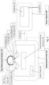
- Fig. 3 is a schematic representation of an analyser 300 for measurement of the composition of a mineral slurry 305, particularly in relation to the measurement of elements in the mineral slurry.
- the analyser 300 includes three components:
- the pipe measurement section 310 consists of a section of pipe 312 which transports the slurry and facilitates the mounting of the measurement probe 320.
- the pipe measurement section 310 includes an aperture to a lumen of the pipe 312, wherein the aperture is surrounded by a pipe mount adapted to couple the measurement probe 320 to the pipe 312.
- the pipe mount may be implemented in many ways, including, for example, but not limited to, a flange adapted to couple to a matching probe mount 355 on the measurement probe 320.
- the pipe mount may optionally be secured to the probe mount 355 by one or more fasteners, wherein the fasteners may include, but are not limited to screws, bolts, threaded screw mounts, dowels, clamps, and the like, or any combination thereof.
- Embodiments may include a seal between the pipe mount and the probe mount 355, such as an O-ring or the like, to prevent leakage of the mineral slurry through the coupling.
- the measurement probe 320 includes a housing 350 for enclosing components of the measurement probe 320.
- the housing 350 includes a slurry window 325 made from material of sufficiently low atomic number and thickness to allow transmission of X-rays of interest into the lumen of the pipe 312.
- the slurry window 325 may be implemented using a material having a low atomic number (Z ⁇ 15 and in some embodiments Z ⁇ 10), including, but not limited to, Poly Ether Ether Ketone (PEEK), boron carbide (B 4 C), polyester (Mylar), polycarbonate, polyamide (Nylon), polytetrafluoroethylene PTFE (Teflon), polystyrene, polyvinylchloride (PVC), magnesium alloy, aluminium alloy, quartz, or fused silica.
- the slurry window 325 is implemented using multi-layered windows to provide protection for the equipment, in the case of a window failure.
- the slurry window 325 is surrounded by the probe mount, such that when the pipe mount is coupled to the probe mount, the slurry window 325 is positioned to provide a transmission window for X-rays to pass between the measurement probe 320 and the lumen of pipe 312.
- the housing of the measurement probe 320 encloses: X-ray source(s) 322 positioned to emit X-rays towards the slurry window 325; X-ray filter(s) 324 and collimator(s) 326 to condition the X-rays; X-ray detector(s) 328 to measure the X-rays from the direction of the slurry window 325; control and processing electronics 340 and associated software which control the analyser and process the X-ray spectrum to yield compositional information regarding the slurry; and active cooling 342 to control the temperature inside the measurement probe 320.
- filters 324 and collimators 326 may be positioned in relation to either one or both of the X-ray source 322 and X-ray detector 328 so as to condition X-rays emitted from the source 322 and detected by the detector 328.
- particular filters 324 may be used when measuring a certain element, in order to increase the signal to noise ratio.
- the control and processing electronics 340 may be implemented using a computing device, alone or in combination with other electrical components.
- Such electronic components may include, for example, a transceiver for communications with an external device, a display, a speaker for audible alerts, mechanical or electrical interlocks, one or more lights (such as LEDs) to act as status indicators, and the like.
- the control and processing electronics 340 stores computer program instructions that when executed on a processor are adapted to: control operation of the X-ray source 322, including turning off and on, and setting the voltage and power; control operation of the X-ray detector 328, including turning off and on, and collecting x-ray spectra (i.e, Fig 2 ); and perform analysis of X-ray spectra to determine elemental abundances in the mineral slurry that is being analysed.
- the measurement probe 320 may optionally include a transceiver (not shown) for remote communications facilities to allow upload/download of data.
- a transceiver for remote communications facilities to allow upload/download of data.
- Such remote communications may be implemented using wired and/or wireless communications, including, for example, but not limited to, Ethernet, ADSL, optical fibre, 3G/4G/5G wireless mobile technologies, LoRa, Zigbee, Sigfox, Bluetooth, WiFi, and any combination thereof.
- the measurement probe 320 includes a wireless transceiver (such as a Bluetooth or WiFi transceiver) for local wireless communications with a mobile computing device, such as a tablet, phablet, laptop, or smartphone.
- One embodiment of the measurement probe 320 uses a Moxtek X-ray source operating at 50kV and a source collimator to restrict X-rays emitted from the X-ray source 322 so that the emitted X-rays impinge only on the slurry window 325.
- This embodiment also uses a source filter to maximise the relative intensity of 35 keV X-rays, an Amptek Silicon Drift Detector (SDD) to detect X-rays emitted from the slurry within the pipe 312, and a Detector Collimator to ensure that the vast majority of detected X-rays originate from the direction of the slurry window 325.
- the X-ray source 322 and X-ray detector 328 are arranged so the axial angle of the X-ray source tube 322 is equal to the axial angle of detection of the detector 328, with respect to the slurry window 325.
- active cooling is achieved through the use of Peltier cooling.
- Efficient heat transfer is achieved through the utilisation of a set of closely coupled fans on the Peltier surface. Insulation on the internal surface of the housing of the measurement probe 320 helps to achieve efficient cooling.
- a thermostat is optionally utilised to ensure that stable temperatures are achieved and maintained.
- the measurement probe 320 is powered by the power cabinet 390.
- the power cabinet 390 is configured to receive AC mains power, such as in the range of 110-240V AC.
- a transformer 392 and other electrical circuitry (not shown), such as a rectifier, convert the AC mains power to a low voltage output power supply to power the measurement probe 320.
- the power cabinet 390 may optionally provide a set of one or more power outlets for general use, wherein the power outlets may provide power at mains voltage, low voltage, or any other voltage value.
- the low voltage output power supply is in the range of 5 to 24V and is coupled to the measurement probe 320 via an outlet using a user-friendly detachable coupling that is readily used by an operator to connect and disconnect the power cabinet 390 to and from the measurement probe 320 as desired.
- the power cabinet 390 may also optionally be actively cooled.
- the outlet may connect power and communications between the measurement probe 320 and the power cabinet 390.
- the outlet may be implemented using a single connector or multiple connectors, depending on the particular application.
- the power cabinet 390 outlet provides wired communications to an internal communications module in the measurement probe 320.
- the internal communications module may be part of the control and processing electronics module 340 or may be implemented using a separate transceiver.
- an analyser in accordance with the present disclosure is utilised to measure palladium (Pd) content within a slurry.
- Software running on the control and processing electronics module 340 receives data derived from X-rays detected by the X-ray detector 328, the data forming X-ray spectra corresponding to the quantity of elements present in the mineral slurry. Irradiation of a palladium bearing slurry results in a characteristic Pd X-ray peak detected at 21.177 keV.
- the control and processing electronics module 340 consisting of steps including normalisation and correction for attenuation effects, the Pd composition of the slurry is calculated.
- two analysers are utilised in a mining concentrator.
- a first analyser is attached to a first pipe carrying feed slurry and a second analyser is attached to a second pipe carrying tailings after mineral content has been extracted from the feed slurry.
- the first and second analysers are used to measure feed and tailings grade continuously, and hence determine mineral recovery in real time.
- X-ray detector may be oriented at greater or lesser angles than the X-ray source, dependent on the operating voltage, collimators, filters, and targeted accuracies for a given slurry measurement application.
- Other embodiments may utilise multiple X-ray sources, operating at the same or different voltages and powers, with the same or different filters and collimators.
- Other embodiments may utilise multiple X-ray sources and detectors, with the same or different filters and collimators.
- the analyser of the present disclosure is different, since it contains the processing electronics (including computer and spectral analysis software) and any other (optional) components such as remote communications and Bluetooth connectivity in the measurement probe, and is directly mounted onto the pipe.
- This has the advantage of ensuring that when the measurement probe leaves the factory, it will have the correct calibration for its particular X-ray source(s), detector(s), filter(s), collimator(s) and any other small changes in geometry typically seen across multiple instances of the same analyser design.
- low atomic number (Z ⁇ 15 and in some embodiments Z ⁇ 10) X-ray windows in the measurement probe allows the measurement of base metals and other elements that emit characteristic X-rays less than approximately 15 keV.
- Such low energy characteristic X-rays are unable to penetrate higher atomic number windows, especially in a mineral processing environment, where slurry pressures as great as 10 atm are expected, and hence necessitate the use of sufficiently thick windows to withstand the pressure.
- the window thickness may be, for example, in the order of approximately 1mm to 5mm, but the actual thickness will depend on the rated pressure required for the pipe and the particular materials used.
- Suitable windows include PEEK (Poly Ether Ether Ketone), boron carbide (B 4 C), polyester (Mylar), polycarbonate, polyamide (Nylon), polytetrafluoroethylene PTFE (Teflon), polystyrene, polyvinylchloride (PVC), magnesium alloy, aluminium alloy, quartz, fused silica, or similar low atomic number materials.
- PEEK Poly Ether Ether Ketone
- boron carbide B 4 C
- polyester Mylar
- polycarbonate polyamide
- Polytetrafluoroethylene PTFE Teflon
- polystyrene polyvinylchloride
- PVC polyvinylchloride
- magnesium alloy aluminium alloy
- quartz fused silica, or similar low atomic number materials.
- the X-ray windows may be implemented using multi-layered windows to provide protection for the equipment, in the case of a window failure.
- the control and processing electronics module 340 of the measurement probe 320 may be practised using a computing device, such as a general-purpose computer or computer server.
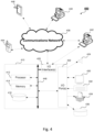
- Fig. 4 is a schematic block diagram of a system 400 that includes a general-purpose computer 410.
- the general-purpose computer 410 includes a plurality of components, including: a processor 412, a memory 414, a storage medium 416, input/output (I/O) interfaces 420, and input/output (I/O) ports 422.
- Components of the general-purpose computer 410 generally communicate using one or more buses 448.
- the memory 414 may be implemented using Random Access Memory (RAM), Read Only Memory (ROM), or a combination thereof.
- the storage medium 416 may be implemented as one or more of a hard disk drive, a solid state "flash" drive, an optical disk drive, or other storage means.
- the storage medium 416 may be utilised to store one or more computer programs, including an operating system, software applications, communications protocols for mining concentrator data systems, and data.
- instructions from one or more computer programs stored in the storage medium 416 are loaded into the memory 414 via the bus 448. Instructions loaded into the memory 414 are then made available via the bus 448 or other means for execution by the processor 412 to implement a mode of operation in accordance with the executed instructions.
- One or more peripheral devices may be coupled to the general-purpose computer 410 via the I/O ports 422.
- the general-purpose computer 410 is coupled to each of a speaker 424, a display device 430, an input device 432, a printer 434, and an external storage medium 436.
- the speaker 424 may be implemented using one or more speakers, and may function to provide audible alerts in relation to the analyser.
- one or more peripheral devices may relate to a speaker or external display screen connected to the I/O ports 422.
- the display device 430 may be a computer monitor, such as a cathode ray tube screen, plasma screen, or liquid crystal display (LCD) screen.
- the display 430 may receive information from the computer 410 in a conventional manner, wherein the information is presented on the display device 430 for viewing by a user.
- the display device 430 may optionally be implemented using a touch screen to enable a user to provide input to the general-purpose computer 410.
- the touch screen may be, for example, a capacitive touch screen, a resistive touchscreen, a surface acoustic wave touchscreen, or the like.
- the display screen may be an LCD screen located on an external surface of the housing of the measurement probe 320 for displaying a status of the probe 320, operating parameters of the probe 320, and composition data relating to X-ray spectra of mineral slurry in the pipe 312.
- the input device 432 may be a keyboard, a mouse, a stylus, drawing tablet, touchscreen, or any combination thereof, for receiving input from a user.
- the I/O interfaces 420 facilitate the exchange of information between the general-purpose computing device 410 and other computing devices.
- the I/O interfaces may be implemented using an internal or external modem, an Ethernet connection, or the like, to enable coupling to a transmission medium.
- the I/O interfaces 422 are coupled to a communications network 438 and directly to a computing device 442.
- the computing device 442 is shown as a personal computer, but may be equally be practised using a smartphone, laptop, or a tablet device.
- Direct communication between the general-purpose computer 410 and the computing device 442 may be implemented using a wireless or wired transmission link. Such a wired or wireless transmission link may be used, for example, to enable a technician or plant operator to monitor data relating to performance of the measurement probe 320 itself or the composition of slurry in the pipe 312.
- the communications network 438 may be implemented using one or more wired or wireless transmission links and may include, for example, a dedicated communications link, a local area network (LAN), a wide area network (WAN), the Internet, a telecommunications network, or any combination thereof.
- a telecommunications network may include, but is not limited to, a telephony network, such as a Public Switch Telephony Network (PSTN), a mobile telephone cellular network, a short message service (SMS) network, or any combination thereof.
- PSTN Public Switch Telephony Network
- SMS short message service
- the general-purpose computer 410 is able to communicate via the communications network 438 to other computing devices connected to the communications network 438, such as the mobile telephone handset 444, the touchscreen smartphone 446, the personal computer 440, the cloud, and the computing device 442.
- One or more instances of the general-purpose computer 410 may be utilised to implement a control and processing electronics module 340 to implement a measurement probe in accordance with the present disclosure.
- the memory 414 and storage 416 are utilised to store data relating to X-ray spectra derived from measurement of mineral slurries in the pipe 312.
- Software for implementing the mineral slurry analysis system is stored in one or both of the memory 414 and storage 416 for execution on the processor 412.
- the software includes computer program code for implementing method steps to control operation of the X-ray source 322 and X-ray detector 328, as well as performing analysis of X-ray spectra to determine slurry composition.
- a measurement probe in accordance with the present disclosure is suitable for use in detecting the quantity of one or more elements of interest in any vessel containing a slurry, such as a stirred slurry tank.
- a measurement probe may utilise the probe mount described above to secure the measurement probe to a vessel mount on the vessel, wherein the vessel mount is similar to the pipe mount describe above.
Landscapes
- Life Sciences & Earth Sciences (AREA)
- Health & Medical Sciences (AREA)
- Chemical & Material Sciences (AREA)
- Analytical Chemistry (AREA)
- Pathology (AREA)
- Immunology (AREA)
- General Physics & Mathematics (AREA)
- General Health & Medical Sciences (AREA)
- Biochemistry (AREA)
- Physics & Mathematics (AREA)
- Engineering & Computer Science (AREA)
- Geology (AREA)
- Medicinal Chemistry (AREA)
- Food Science & Technology (AREA)
- Remote Sensing (AREA)
- General Life Sciences & Earth Sciences (AREA)
- Environmental & Geological Engineering (AREA)
- Analysing Materials By The Use Of Radiation (AREA)
Description
- This application is related to
Australian Provisional Patent Application No. 2018903029 titled "Apparatus for the measurement of mineral slurries" and filed 17 August 2019 - The present disclosure relates to an apparatus for measuring elements within a mineral slurry. In particular, the present disclosure relates to an analyser for measuring elements within a mineral slurry by utilising X-ray fluorescence (XRF).
- Ores are extracted from the earth through mining and the ores are then processed, using mineral processing, to separate commercially valuable minerals from their respective ores. Mineral processing may involve a number of different sequential steps to identify and separate various minerals from raw material extracted from a mine. Such steps depend on the particular mineral to be extracted and the mining operation, but may include, for example, crushing, vibrating, flotation, and the like.
- During mineral processing, it is common to form a slurry from mixing crushed raw material with water, as slurries are a convenient way by which to transport and handle bulk materials.
- At the beginning of a mineral processing arrangement, it is important to identify the amount of various elements in the slurry to be processed. After the slurry has been processed and the valuable mineral content has been extracted, the waste product is known as tailings. It is important to identify the amount of elements remaining in the slurry tailings, so that the efficiency of the mineral processing can be assessed.
-
US5982847 discloses an X-ray fluorescence spectrometer for real-time wear metal analysis of lubricating oils. - Thus, a need exists to provide an improved apparatus for measuring elements in a mineral slurry.
- The present disclosure relates to an analyser for the measurement of elements in a mineral slurry using XRF.
- A first aspect of the present disclosure provides a measurement probe as defined in the claims appended hereto.
- A second aspect of the present disclosure provides an analyser for measurement of elements in a mineral slurry as defined in the claims appended hereto.
- One or more embodiments of the present disclosure will now be described by way of specific example(s) with reference to the accompanying drawings, in which:
-
Fig. 1 is a schematic representation of an X-ray fluorescence (XRF) apparatus, suitable for use in measuring elements in a mineral slurry; -
Fig. 2 is a schematic representation of a simplified XRF spectrum; and -
Fig. 3 is a schematic representation of an apparatus for measurement of elements in a mineral slurry; and -
Fig. 4 is a schematic block diagram representation of a system that includes a general-purpose computer on which one or more embodiments of the present disclosure may be practised. - Method steps or features in the accompanying drawings that have the same reference numerals are to be considered to have the same function(s) or operation(s), unless the contrary intention is expressed or implied.
- The present disclosure provides an apparatus suitable for use in measuring elements in a mineral slurry by utilising X-ray fluorescence (XRF) analysis. The apparatus of the present disclosure is an analyser that is adapted to be positioned on a pipe containing a slurry, such that an X-ray source of the analyser is directed through an X-ray window of the analyser to be incident on the slurry within the pipe. An X-ray detector of the analyser detects scattered and emitted X-rays and the analyser processes data derived from the detected X-rays to determine the quantity of one or more elements of interest in the mineral slurry.
-
Fig. 1 is a schematic representation of an X-ray fluorescence (XRF)apparatus 100. TheXRF apparatus 100 includes anX-ray source 110 that is used to generate X-rays, which are a form of electromagnetic radiation. X-rays typically have a wavelength ranging from 0.01 to 10 nanometres and energies in therange 100 eV to 100 keV. TheX-ray source 110 is positioned relative to asample 190, such that X-rays emitted from theX-ray source 110 are incidence on thesample 190. - In the example of
Fig. 1 , the XRF apparatus includesfilters 115, which are positioned between theX-ray source 110 and thesample 190 so as to attenuate X-rays emitted from theX-ray source 110. Filtering the X-rays may be used to filter out X-rays that are not of the appropriate wavelength and/or energy for the element(s) in the sample to be studied. TheXRF apparatus 100 also includes anX-ray detector 120, which is adapted to receive and detect X-rays scattered from or emitted from thesample 190. Further, theXRF apparatus 100 includescollimators 125, which restrict X-rays emitted from theX-ray source 110 so that those emitted source X-rays are directed towards thesample 190, and also restricts X-rays from thesample 190 so that those emitted sample X-rays are directed towards theX-ray detector 120. - The
X-ray source 110 emits X-rays directed at thesample 190. When an X-ray strikes thesample 190, the incident X-ray may be absorbed by an electron in an atom of thesample 190. If the electron is ejected during this process (known as the photoelectric effect), then a vacancy is created in an atomic orbital. When this vacancy in the atomic orbital is filled, via the transition of a higher orbital electron, the excess energy may be emitted as a characteristic X-ray whose energy is the difference between the corresponding atomic orbitals. Since each element has a unique set of orbitals, then the characteristic X-rays are unique for each element. The emitted characteristic X-rays are then received by theX-ray detector 120, which may be implemented using an Energy Dispersive detector. In particular, a Silicon Drift Detector (SDD) is particularly suitable for such an analyser. The process of measuring the emissions of characteristic X-rays and determining the elemental abundances is typically called XRF analysis. - As shown in
Fig. 1 , theXRF apparatus 100 includescollimators 125 andfilters 115, which may be used to condition the X-rays impinging on thesample 190 and theX-ray detector 120. Differing combinations ofX-ray sources 110,filters 115,collimators 125,samples 190, andX-ray detectors 120 are widely used in a variety of modern day commercial XRF instrumentation. -
Fig. 2 shows asimplified X-ray spectrum 200 measured by an Energy Dispersive X-ray detector. Thespectrum 200 consists of one or more characteristic X-ray peaks from the elements present in the sample, and additionally one or more Compton and Rayleigh peaks due the scattering of X-rays in the sample. In general, the heights of the characteristic X-ray peaks are related to their corresponding elemental abundances, whereas the Compton and Rayleigh peaks are more complexly related to the overall slurry composition. - XRF analysis techniques are particularly suitable for deployment in the mining industry, where timely characterisation of the elemental composition of a mineral slurry may result in vastly improved economics. For example, a mineral concentrator is where mineral bearing ore is processed. As part of this process, mined ore is crushed and milled, and water and chemicals are added to produce a slurry. The mineral bearing slurry is then processed via a variety of techniques, including flotation and gravity concentration, to produce a high grade slurry "concentrate", which is recovered. The waste slurry "tailings" typically exit the plant and are discarded. Timely characterisation of the slurry, via X-ray techniques, can yield much information regarding the operational state of the concentrator, resulting in much improved recovery of the valuable elements and minerals.
-
Fig. 3 is a schematic representation of an analyser 300 for measurement of the composition of amineral slurry 305, particularly in relation to the measurement of elements in the mineral slurry. The analyser 300 includes three components: - 1. a
pipe measurement section 310; - 2. a
measurement probe 320; and - 3. a
power cabinet 390. - The
pipe measurement section 310 consists of a section ofpipe 312 which transports the slurry and facilitates the mounting of themeasurement probe 320. Thepipe measurement section 310 includes an aperture to a lumen of thepipe 312, wherein the aperture is surrounded by a pipe mount adapted to couple themeasurement probe 320 to thepipe 312. - The pipe mount may be implemented in many ways, including, for example, but not limited to, a flange adapted to couple to a matching probe mount 355 on the
measurement probe 320. The pipe mount may optionally be secured to the probe mount 355 by one or more fasteners, wherein the fasteners may include, but are not limited to screws, bolts, threaded screw mounts, dowels, clamps, and the like, or any combination thereof. Embodiments may include a seal between the pipe mount and the probe mount 355, such as an O-ring or the like, to prevent leakage of the mineral slurry through the coupling. - In the example of
Fig. 3 , themeasurement probe 320 includes a housing 350 for enclosing components of themeasurement probe 320. The housing 350 includes aslurry window 325 made from material of sufficiently low atomic number and thickness to allow transmission of X-rays of interest into the lumen of thepipe 312. Theslurry window 325 may be implemented using a material having a low atomic number (Z<15 and in some embodiments Z<10), including, but not limited to, Poly Ether Ether Ketone (PEEK), boron carbide (B4C), polyester (Mylar), polycarbonate, polyamide (Nylon), polytetrafluoroethylene PTFE (Teflon), polystyrene, polyvinylchloride (PVC), magnesium alloy, aluminium alloy, quartz, or fused silica. In one or more embodiments, theslurry window 325 is implemented using multi-layered windows to provide protection for the equipment, in the case of a window failure. - The
slurry window 325 is surrounded by the probe mount, such that when the pipe mount is coupled to the probe mount, theslurry window 325 is positioned to provide a transmission window for X-rays to pass between themeasurement probe 320 and the lumen ofpipe 312. - The housing of the
measurement probe 320 encloses: X-ray source(s) 322 positioned to emit X-rays towards theslurry window 325; X-ray filter(s) 324 and collimator(s) 326 to condition the X-rays; X-ray detector(s) 328 to measure the X-rays from the direction of theslurry window 325; control andprocessing electronics 340 and associated software which control the analyser and process the X-ray spectrum to yield compositional information regarding the slurry; andactive cooling 342 to control the temperature inside themeasurement probe 320. - Various combinations of
filters 324 andcollimators 326 may be positioned in relation to either one or both of theX-ray source 322 andX-ray detector 328 so as to condition X-rays emitted from thesource 322 and detected by thedetector 328. For example,particular filters 324 may be used when measuring a certain element, in order to increase the signal to noise ratio. - The control and
processing electronics 340 may be implemented using a computing device, alone or in combination with other electrical components. Such electronic components may include, for example, a transceiver for communications with an external device, a display, a speaker for audible alerts, mechanical or electrical interlocks, one or more lights (such as LEDs) to act as status indicators, and the like. - The control and
processing electronics 340 stores computer program instructions that when executed on a processor are adapted to: control operation of theX-ray source 322, including turning off and on, and setting the voltage and power; control operation of theX-ray detector 328, including turning off and on, and collecting x-ray spectra (i.e,Fig 2 ); and perform analysis of X-ray spectra to determine elemental abundances in the mineral slurry that is being analysed. - The
measurement probe 320 may optionally include a transceiver (not shown) for remote communications facilities to allow upload/download of data. Such remote communications may be implemented using wired and/or wireless communications, including, for example, but not limited to, Ethernet, ADSL, optical fibre, 3G/4G/5G wireless mobile technologies, LoRa, Zigbee, Sigfox, Bluetooth, WiFi, and any combination thereof. In one implementation, themeasurement probe 320 includes a wireless transceiver (such as a Bluetooth or WiFi transceiver) for local wireless communications with a mobile computing device, such as a tablet, phablet, laptop, or smartphone. - One embodiment of the
measurement probe 320 uses a Moxtek X-ray source operating at 50kV and a source collimator to restrict X-rays emitted from theX-ray source 322 so that the emitted X-rays impinge only on theslurry window 325. This embodiment also uses a source filter to maximise the relative intensity of 35 keV X-rays, an Amptek Silicon Drift Detector (SDD) to detect X-rays emitted from the slurry within thepipe 312, and a Detector Collimator to ensure that the vast majority of detected X-rays originate from the direction of theslurry window 325. TheX-ray source 322 andX-ray detector 328 are arranged so the axial angle of theX-ray source tube 322 is equal to the axial angle of detection of thedetector 328, with respect to theslurry window 325. - In one arrangement, active cooling is achieved through the use of Peltier cooling. Efficient heat transfer is achieved through the utilisation of a set of closely coupled fans on the Peltier surface. Insulation on the internal surface of the housing of the
measurement probe 320 helps to achieve efficient cooling. A thermostat is optionally utilised to ensure that stable temperatures are achieved and maintained. - The
measurement probe 320 is powered by thepower cabinet 390. In the example ofFig. 3 , thepower cabinet 390 is configured to receive AC mains power, such as in the range of 110-240V AC. Atransformer 392 and other electrical circuitry (not shown), such as a rectifier, convert the AC mains power to a low voltage output power supply to power themeasurement probe 320. Thepower cabinet 390 may optionally provide a set of one or more power outlets for general use, wherein the power outlets may provide power at mains voltage, low voltage, or any other voltage value. - In the example of
Fig. 3 , the low voltage output power supply is in the range of 5 to 24V and is coupled to themeasurement probe 320 via an outlet using a user-friendly detachable coupling that is readily used by an operator to connect and disconnect thepower cabinet 390 to and from themeasurement probe 320 as desired. Thepower cabinet 390 may also optionally be actively cooled. Depending on the implementation, the outlet may connect power and communications between themeasurement probe 320 and thepower cabinet 390. The outlet may be implemented using a single connector or multiple connectors, depending on the particular application. - In one arrangement, the
power cabinet 390 outlet provides wired communications to an internal communications module in themeasurement probe 320. The internal communications module may be part of the control andprocessing electronics module 340 or may be implemented using a separate transceiver. - In one example, an analyser in accordance with the present disclosure is utilised to measure palladium (Pd) content within a slurry. Software running on the control and
processing electronics module 340 receives data derived from X-rays detected by theX-ray detector 328, the data forming X-ray spectra corresponding to the quantity of elements present in the mineral slurry. Irradiation of a palladium bearing slurry results in a characteristic Pd X-ray peak detected at 21.177 keV. After processing by the control andprocessing electronics module 340, consisting of steps including normalisation and correction for attenuation effects, the Pd composition of the slurry is calculated. - In one implementation, two analysers are utilised in a mining concentrator. A first analyser is attached to a first pipe carrying feed slurry and a second analyser is attached to a second pipe carrying tailings after mineral content has been extracted from the feed slurry. The first and second analysers are used to measure feed and tailings grade continuously, and hence determine mineral recovery in real time.
- Other embodiments may utilise an X-ray source operating at higher or lower target voltages. Similarly, the X-ray detector may be oriented at greater or lesser angles than the X-ray source, dependent on the operating voltage, collimators, filters, and targeted accuracies for a given slurry measurement application.
- Other embodiments may utilise multiple X-ray sources, operating at the same or different voltages and powers, with the same or different filters and collimators.
- Other embodiments may utilise multiple detectors, with the same or different filters and collimators.
- Other embodiments may utilise multiple X-ray sources and detectors, with the same or different filters and collimators.
- Whilst XRF instrumentation has been used to make measurements on pipes, the analyser of the present disclosure is different, since it contains the processing electronics (including computer and spectral analysis software) and any other (optional) components such as remote communications and Bluetooth connectivity in the measurement probe, and is directly mounted onto the pipe. This has the advantage of ensuring that when the measurement probe leaves the factory, it will have the correct calibration for its particular X-ray source(s), detector(s), filter(s), collimator(s) and any other small changes in geometry typically seen across multiple instances of the same analyser design.
- The incorporation of active cooling, such as Peltier, to control the temperature inside the measurement probe ensures increased reliability. This is particularly important for mining sites located in remoted areas, where the maximum possible reliability is of great value. The increased cost and complexity of active cooling is more than offset by the advantages of improved reliability.
- The incorporation of low atomic number (Z<15 and in some embodiments Z<10) X-ray windows in the measurement probe allows the measurement of base metals and other elements that emit characteristic X-rays less than approximately 15 keV. Such low energy characteristic X-rays are unable to penetrate higher atomic number windows, especially in a mineral processing environment, where slurry pressures as great as 10 atm are expected, and hence necessitate the use of sufficiently thick windows to withstand the pressure. Depending on the application, the window thickness may be, for example, in the order of approximately 1mm to 5mm, but the actual thickness will depend on the rated pressure required for the pipe and the particular materials used. Examples of suitable windows include PEEK (Poly Ether Ether Ketone), boron carbide (B4C), polyester (Mylar), polycarbonate, polyamide (Nylon), polytetrafluoroethylene PTFE (Teflon), polystyrene, polyvinylchloride (PVC), magnesium alloy, aluminium alloy, quartz, fused silica, or similar low atomic number materials. As indicated with reference to
Fig. 3 , the X-ray windows may be implemented using multi-layered windows to provide protection for the equipment, in the case of a window failure. - Other embodiments may use higher atomic number windows if the measurement of characteristic X-rays less than approximately 15 keV is not desirable.
- The control and
processing electronics module 340 of themeasurement probe 320 may be practised using a computing device, such as a general-purpose computer or computer server.Fig. 4 is a schematic block diagram of asystem 400 that includes a general-purpose computer 410. The general-purpose computer 410 includes a plurality of components, including: aprocessor 412, amemory 414, astorage medium 416, input/output (I/O) interfaces 420, and input/output (I/O)ports 422. Components of the general-purpose computer 410 generally communicate using one ormore buses 448. - The
memory 414 may be implemented using Random Access Memory (RAM), Read Only Memory (ROM), or a combination thereof. Thestorage medium 416 may be implemented as one or more of a hard disk drive, a solid state "flash" drive, an optical disk drive, or other storage means. Thestorage medium 416 may be utilised to store one or more computer programs, including an operating system, software applications, communications protocols for mining concentrator data systems, and data. In one mode of operation, instructions from one or more computer programs stored in thestorage medium 416 are loaded into thememory 414 via thebus 448. Instructions loaded into thememory 414 are then made available via thebus 448 or other means for execution by theprocessor 412 to implement a mode of operation in accordance with the executed instructions. - One or more peripheral devices may be coupled to the general-
purpose computer 410 via the I/O ports 422. In the example ofFig. 4 , the general-purpose computer 410 is coupled to each of aspeaker 424, adisplay device 430, aninput device 432, aprinter 434, and anexternal storage medium 436. Thespeaker 424 may be implemented using one or more speakers, and may function to provide audible alerts in relation to the analyser. In the example in which the general-purpose computer 410 is utilised to implement the control andprocessing module 340 of themeasurement probe 320 ofFig. 3 , one or more peripheral devices may relate to a speaker or external display screen connected to the I/O ports 422. - The
display device 430 may be a computer monitor, such as a cathode ray tube screen, plasma screen, or liquid crystal display (LCD) screen. Thedisplay 430 may receive information from thecomputer 410 in a conventional manner, wherein the information is presented on thedisplay device 430 for viewing by a user. Thedisplay device 430 may optionally be implemented using a touch screen to enable a user to provide input to the general-purpose computer 410. The touch screen may be, for example, a capacitive touch screen, a resistive touchscreen, a surface acoustic wave touchscreen, or the like. For example, the display screen may be an LCD screen located on an external surface of the housing of themeasurement probe 320 for displaying a status of theprobe 320, operating parameters of theprobe 320, and composition data relating to X-ray spectra of mineral slurry in thepipe 312. - The
input device 432 may be a keyboard, a mouse, a stylus, drawing tablet, touchscreen, or any combination thereof, for receiving input from a user. - The I/O interfaces 420 facilitate the exchange of information between the general-
purpose computing device 410 and other computing devices. The I/O interfaces may be implemented using an internal or external modem, an Ethernet connection, or the like, to enable coupling to a transmission medium. In the example ofFig. 4 , the I/O interfaces 422 are coupled to acommunications network 438 and directly to acomputing device 442. Thecomputing device 442 is shown as a personal computer, but may be equally be practised using a smartphone, laptop, or a tablet device. Direct communication between the general-purpose computer 410 and thecomputing device 442 may be implemented using a wireless or wired transmission link. Such a wired or wireless transmission link may be used, for example, to enable a technician or plant operator to monitor data relating to performance of themeasurement probe 320 itself or the composition of slurry in thepipe 312. - The
communications network 438 may be implemented using one or more wired or wireless transmission links and may include, for example, a dedicated communications link, a local area network (LAN), a wide area network (WAN), the Internet, a telecommunications network, or any combination thereof. A telecommunications network may include, but is not limited to, a telephony network, such as a Public Switch Telephony Network (PSTN), a mobile telephone cellular network, a short message service (SMS) network, or any combination thereof. The general-purpose computer 410 is able to communicate via thecommunications network 438 to other computing devices connected to thecommunications network 438, such as themobile telephone handset 444, thetouchscreen smartphone 446, thepersonal computer 440, the cloud, and thecomputing device 442. - One or more instances of the general-
purpose computer 410 may be utilised to implement a control andprocessing electronics module 340 to implement a measurement probe in accordance with the present disclosure. In such an embodiment, thememory 414 andstorage 416 are utilised to store data relating to X-ray spectra derived from measurement of mineral slurries in thepipe 312. Software for implementing the mineral slurry analysis system is stored in one or both of thememory 414 andstorage 416 for execution on theprocessor 412. The software includes computer program code for implementing method steps to control operation of theX-ray source 322 andX-ray detector 328, as well as performing analysis of X-ray spectra to determine slurry composition. - Whilst the embodiment described above refer to analysing mineral slurry in a pipe, a measurement probe in accordance with the present disclosure is suitable for use in detecting the quantity of one or more elements of interest in any vessel containing a slurry, such as a stirred slurry tank. Such a measurement probe may utilise the probe mount described above to secure the measurement probe to a vessel mount on the vessel, wherein the vessel mount is similar to the pipe mount describe above.
- The arrangements described are applicable to the mining and mineral processing industries.
- The foregoing describes only some embodiments of the present invention, and modifications and/or changes can be made thereto without departing from the scope of the invention, the embodiments being illustrative and not restrictive. Although the invention has been described with reference to specific examples, it will be appreciated by those skilled in the art that the invention may be embodied in many other forms.
- In the context of this specification, the word "comprising" and its associated grammatical constructions mean "including principally but not necessarily solely" or "having" or "including", and not "consisting only of". Variations of the word "comprising", such as "comprise" and "comprises" have correspondingly varied meanings.
- As used throughout this specification, unless otherwise specified, the use of ordinal adjectives "first", "second", "third", "fourth", etc., to describe common or related objects, indicates that reference is being made to different instances of those common or related objects, and is not intended to imply that the objects so described must be provided or positioned in a given order or sequence, either temporally, spatially, in ranking, or in any other manner.
Claims (15)
- A measurement probe (320) for measurement of elements in a mineral slurry (305), said probe (320) comprising:a housing (350) having an X-ray window (325), said housing (350) enclosing:an electrically powered X-ray source (322) positioned to emit source X-rays at said X-ray window (325);an X-ray detector (328) positioned to detect X-rays from said X-ray window (325); anda control module (340) configured to:control operation of said X-ray source (322) and said X-ray detector (328);process X-rays detected by said X-ray detector (328) to generate X-ray spectra data; andprocess said X-ray spectra data to determine the quantity of one or more elements of interest in the mineral slurry (305); anda probe mount (355) located on an outer surface of said housing (350) and surrounding said X-ray window (325), said probe mount (355) being adapted to couple said measurement probe (320) to a pipe mount on a pipe (312) or a vessel mount on a vessel carrying said mineral slurry (305), said pipe mount or vessel mount surrounding an aperture to a lumen of said respective pipe (312) or vessel, such that when said probe mount (355) is coupled to said pipe mount or vessel mount the X-ray window (325) provides a transmission window for X-rays into said lumen of said pipe (312) or vessel.
- The measurement probe (320) according to claim 1, further comprising active cooling (342) that uses at least one Peltier device to control temperature inside the measurement probe (320).
- The measurement probe (320) according to claim 2, wherein said active cooling (342) further includes a set of one or more fans.
- The measurement probe (320) according to any one of claims 1 to 3, further comprising a set of filters (324) and/or collimators (326) located to condition at least one of source X-rays emitted from said X-ray source (322) and X-rays received through said X-ray window (325).
- The measurement probe (320) according to any one of claims 1 to 4, wherein said probe (320) is powered by a low voltage power supply.
- The measurement probe (320) according to any one of claims 1 to 5, wherein said X-ray window (325) is made from a low atomic number material.
- The measurement probe (320) according to claim 6, wherein said X-ray window (325) is a multi-layered window.
- The measurement probe (320) according to any one of claims 1 to 7, further comprising an outlet for releasably coupling said probe (320) to a power cabinet (390) providing a low voltage power supply.
- The measurement probe (320) according to claim 8, wherein said outlet includes a communications interface for exchanging slurry composition data with an external communications module in said power cabinet (390).
- The measurement probe (320) according to either one of claims 8 and 9, wherein said power cabinet (390) receives input mains power and outputs low voltage direct current (DC) power to said measurement probe (320) via said outlet.
- The measurement probe (320) according to any one of claims 1 to 10, further comprising an internal communications module for outputting slurry composition data, wherein said internal communications module includes one of a wired transceiver and a wireless transceiver.
- The measurement probe (320) according to claim 11, wherein said internal communications module is a wireless transceiver implemented using one of 3G/4G/5G wireless mobile technologies, LoRa, Zigbee, Sigfox, Bluetooth, and WiFi.
- The measurement probe (320) according to any one of claims 1 to 12, further comprising a plurality of X-ray sources (322) positioned to emit source X-rays at said X-ray window (325).
- The measurement probe (320) according to any one of claims 1 to 13, further comprising a plurality of X-ray detectors (328) positioned to detect X-rays from said X-ray window (325).
- An analyser (300) for measurement of elements in a mineral slurry (305), said analyser (300) comprising:a pipe mount on a pipe (312) or a vessel mount on a vessel carrying said mineral slurry, said pipe mount or vessel mount surrounding an aperture to a lumen of said pipe (312) or vessel, respectively;a power cabinet (390) configured to receive mains power and output low voltage power;a measurement probe (320) according to any one of claims 1 to 14;wherein said power cabinet (390) is coupled to said measurement probe (320) to power said measurement probe (320).
Applications Claiming Priority (2)
| Application Number | Priority Date | Filing Date | Title |
|---|---|---|---|
| AU2018903029A AU2018903029A0 (en) | 2018-08-17 | Apparatus for the measurement of mineral slurries | |
| PCT/AU2019/050852 WO2020034002A1 (en) | 2018-08-17 | 2019-08-15 | Apparatus for the measurement of mineral slurries |
Publications (4)
| Publication Number | Publication Date |
|---|---|
| EP3837536A1 EP3837536A1 (en) | 2021-06-23 |
| EP3837536A4 EP3837536A4 (en) | 2022-04-27 |
| EP3837536C0 EP3837536C0 (en) | 2025-02-12 |
| EP3837536B1 true EP3837536B1 (en) | 2025-02-12 |
Family
ID=69524559
Family Applications (1)
| Application Number | Title | Priority Date | Filing Date |
|---|---|---|---|
| EP19849813.1A Active EP3837536B1 (en) | 2018-08-17 | 2019-08-15 | Apparatus for the measurement of mineral slurries |
Country Status (6)
| Country | Link |
|---|---|
| US (1) | US11644431B2 (en) |
| EP (1) | EP3837536B1 (en) |
| AU (1) | AU2019322935B2 (en) |
| CL (1) | CL2021000388A1 (en) |
| WO (1) | WO2020034002A1 (en) |
| ZA (1) | ZA202101521B (en) |
Families Citing this family (2)
| Publication number | Priority date | Publication date | Assignee | Title |
|---|---|---|---|---|
| JP7563304B2 (en) * | 2021-06-16 | 2024-10-08 | トヨタ自動車株式会社 | X-ray CT device and image generating method |
| CN116124781A (en) * | 2023-04-20 | 2023-05-16 | 矿冶科技集团有限公司 | Ore pulp detection device |
Citations (1)
| Publication number | Priority date | Publication date | Assignee | Title |
|---|---|---|---|---|
| WO2003049138A2 (en) * | 2001-12-04 | 2003-06-12 | X-Ray Optical Systems, Inc. | Method and device for cooling and electrically insulating a high-voltage, heat-generating component such as an x-ray tube |
Family Cites Families (45)
| Publication number | Priority date | Publication date | Assignee | Title |
|---|---|---|---|---|
| US4450576A (en) * | 1979-04-20 | 1984-05-22 | Gesellschaft mit Kernforschungszentrum Karlsruhe beschrankter Haftung | Apparatus for continuously measuring the element content in slurries |
| DE2915986C2 (en) * | 1979-04-20 | 1982-04-08 | Kernforschungszentrum Karlsruhe Gmbh, 7500 Karlsruhe | Process for the continuous measurement of element contents |
| US4916719A (en) * | 1988-06-07 | 1990-04-10 | Board Of Control Of Michigan Technological University | On-line analysis of ash containing slurries |
| FR2741155B1 (en) * | 1995-11-15 | 1997-12-05 | Commissariat Energie Atomique | APPARATUS FOR ANALYZING A FLUORESCENCE X SOLUTION |
| US5982847A (en) | 1996-10-28 | 1999-11-09 | Utah State University | Compact X-ray fluorescence spectrometer for real-time wear metal analysis of lubrucating oils |
| US5818899A (en) * | 1997-04-02 | 1998-10-06 | Mcdermott Technology, Inc. | X-ray fluorescence analysis of pulverized coal |
| US6012325A (en) * | 1997-11-05 | 2000-01-11 | The Boc Group, Inc. (A Delaware Corporation) | Method and apparatus for measuring metallic impurities contained within a fluid |
| DE19820321B4 (en) * | 1998-05-07 | 2004-09-16 | Bruker Axs Gmbh | Compact x-ray spectrometer |
| JP3062685B2 (en) * | 1998-07-23 | 2000-07-12 | セイコーインスツルメンツ株式会社 | X-ray fluorescence analyzer |
| US6266390B1 (en) * | 1998-09-21 | 2001-07-24 | Spectramet, Llc | High speed materials sorting using x-ray fluorescence |
| JP3284198B2 (en) * | 1998-10-30 | 2002-05-20 | 理学電機工業株式会社 | X-ray fluorescence analyzer |
| KR101063106B1 (en) * | 2004-11-08 | 2011-09-07 | 에스아이아이 나노 테크놀로지 가부시키가이샤 | Fluorescence X-ray Analyzer |
| US7796726B1 (en) * | 2006-02-14 | 2010-09-14 | University Of Maryland, Baltimore County | Instrument and method for X-ray diffraction, fluorescence, and crystal texture analysis without sample preparation |
| JP4854005B2 (en) * | 2006-02-24 | 2012-01-11 | エスアイアイ・ナノテクノロジー株式会社 | X-ray fluorescence analyzer |
| JP4849957B2 (en) * | 2006-05-26 | 2012-01-11 | エスアイアイ・ナノテクノロジー株式会社 | X-ray fluorescence analyzer |
| US7474730B2 (en) * | 2006-10-17 | 2009-01-06 | Oxford Instruments Analytical Oy | Compensation for fluctuations over time in the radiation characteristics of the X-ray source in an XRF analyser |
| US8064570B2 (en) * | 2006-12-20 | 2011-11-22 | Innov-X-Systems, Inc. | Hand-held XRF analyzer |
| US7587025B2 (en) * | 2007-01-23 | 2009-09-08 | Sii Nanotechnology Inc. | X-ray analysis apparatus and X-ray analysis method |
| US7680248B2 (en) * | 2007-01-30 | 2010-03-16 | Sii Nanotechnology Inc. | X-ray tube and X-ray analyzing apparatus |
| US7916834B2 (en) * | 2007-02-12 | 2011-03-29 | Thermo Niton Analyzers Llc | Small spot X-ray fluorescence (XRF) analyzer |
| JP4956701B2 (en) * | 2007-07-28 | 2012-06-20 | エスアイアイ・ナノテクノロジー株式会社 | X-ray tube and X-ray analyzer |
| JP5135602B2 (en) * | 2007-07-28 | 2013-02-06 | エスアイアイ・ナノテクノロジー株式会社 | X-ray tube and X-ray analyzer |
| CN103411988B (en) * | 2008-07-01 | 2016-05-18 | XRpro科学有限公司 | For measuring the method and apparatus of analyte across barrier transhipment |
| JP2012512394A (en) * | 2008-12-12 | 2012-05-31 | サーモ ニトン アナライザーズ リミテッド ライアビリティ カンパニー | Automatic sum peak suppression in X-ray fluorescence analyzers |
| CN102042991A (en) * | 2009-10-09 | 2011-05-04 | 株式会社堀场制作所 | Sample cell for fluorescent X-ray analysis and sample cell assembly instrument |
| PL2533267T3 (en) * | 2011-06-10 | 2014-09-30 | Outotec Oyj | X-ray tube and X-ray fluorescence analyser utilizing selective excitation radiation |
| DE102011051365B4 (en) * | 2011-06-27 | 2013-08-22 | Rayonic Sensor Systems Gmbh | Detection device and system for measuring the thickness of a zinc layer on steel and measuring the iron content of a zinc layer |
| US9176080B2 (en) * | 2011-07-19 | 2015-11-03 | Olympus Ndt, Inc. | X-ray analysis apparatus with detector window protection feature |
| WO2013025682A2 (en) * | 2011-08-15 | 2013-02-21 | X-Ray Optical Systems, Inc. | Sample viscosity and flow control for heavy samples, and x-ray analysis applications thereof |
| US8982338B2 (en) * | 2012-05-31 | 2015-03-17 | Thermo Scientific Portable Analytical Instruments Inc. | Sample analysis |
| US9683952B2 (en) * | 2014-01-24 | 2017-06-20 | Olympus Scientific Solutions Americas Inc. | Test stand for XRF instrument enabling multi-way operation |
| MX2017000147A (en) * | 2014-06-23 | 2017-04-25 | Charles Stark Draper Laboratory Inc | Injection well identification using tracer particles. |
| DE102014115383A1 (en) * | 2014-08-01 | 2016-02-04 | Helmut Fischer GmbH Institut für Elektronik und Messtechnik | Handheld device and mobile device for X-ray fluorescence analysis |
| US9689815B2 (en) * | 2014-09-12 | 2017-06-27 | Moxtek, Inc. | XRF analyzer rotational filter |
| US9746432B2 (en) * | 2014-09-23 | 2017-08-29 | Olympus Scientific Solutions Americas Inc. | Spacer accessory for XRF handheld analyzers |
| WO2016068863A1 (en) * | 2014-10-28 | 2016-05-06 | Halliburton Energy Services, Inc. | Pneumatic conveying system and method using optical flow characterization data |
| US10018748B2 (en) * | 2015-01-16 | 2018-07-10 | Saudi Arabian Oil Company | Inline density and fluorescence spectrometry meter |
| US10295486B2 (en) * | 2015-08-18 | 2019-05-21 | Sigray, Inc. | Detector for X-rays with high spatial and high spectral resolution |
| US9976972B2 (en) * | 2015-12-15 | 2018-05-22 | Thermo Gamma-Metrics Pty Ltd | Thermal control apparatus |
| FR3052259B1 (en) * | 2016-06-02 | 2023-08-25 | Avenisense | SENSOR, METHOD FOR CALIBRATING A SENSOR AND AUTOMATED METHOD FOR ONLINE MONITORING OF THE EVOLUTION OF A LIQUID BODY |
| US10663415B2 (en) * | 2016-06-27 | 2020-05-26 | Shimadzu Corporation | Analysis device |
| US10641718B2 (en) * | 2016-07-29 | 2020-05-05 | Bruker Handheld Llc | X-ray fluorescence analyzer |
| US11169100B2 (en) * | 2018-04-02 | 2021-11-09 | Sciaps, Inc. | Portable, hand held aluminum alloy XRF analyzer and method |
| SE544472C2 (en) * | 2018-04-20 | 2022-06-14 | Outotec Finland Oy | X-ray fluorescence analyzer with a plurality of measurement channels, and a method for performing x-ray fluorescence analysis |
| MX2020011022A (en) * | 2018-04-20 | 2021-01-29 | Outotec Finland Oy | X-ray fluorescence analyzer, and a method for performing x-ray fluorescence analysis. |
-
2019
- 2019-08-15 WO PCT/AU2019/050852 patent/WO2020034002A1/en not_active Ceased
- 2019-08-15 AU AU2019322935A patent/AU2019322935B2/en active Active
- 2019-08-15 EP EP19849813.1A patent/EP3837536B1/en active Active
- 2019-08-15 US US17/268,922 patent/US11644431B2/en active Active
-
2021
- 2021-02-15 CL CL2021000388A patent/CL2021000388A1/en unknown
- 2021-03-05 ZA ZA2021/01521A patent/ZA202101521B/en unknown
Patent Citations (1)
| Publication number | Priority date | Publication date | Assignee | Title |
|---|---|---|---|---|
| WO2003049138A2 (en) * | 2001-12-04 | 2003-06-12 | X-Ray Optical Systems, Inc. | Method and device for cooling and electrically insulating a high-voltage, heat-generating component such as an x-ray tube |
Also Published As
| Publication number | Publication date |
|---|---|
| US11644431B2 (en) | 2023-05-09 |
| WO2020034002A1 (en) | 2020-02-20 |
| EP3837536C0 (en) | 2025-02-12 |
| EP3837536A1 (en) | 2021-06-23 |
| AU2019322935B2 (en) | 2022-03-10 |
| CL2021000388A1 (en) | 2021-09-10 |
| ZA202101521B (en) | 2023-11-29 |
| EP3837536A4 (en) | 2022-04-27 |
| CA3151147A1 (en) | 2020-02-20 |
| US20210310969A1 (en) | 2021-10-07 |
| AU2019322935A1 (en) | 2021-04-08 |
Similar Documents
| Publication | Publication Date | Title |
|---|---|---|
| AU2021107550A4 (en) | X-ray fluorescence analyzer, and a method for performing x-ray fluorescence analysis | |
| Negrello et al. | Astrophysical and cosmological information from large-scale submillimetre surveys of extragalactic sources | |
| AU2019322935B2 (en) | Apparatus for the measurement of mineral slurries | |
| AU2021102216A4 (en) | X-ray fluorescence analyzer with a plurality of measurement channels, and a method for performing x-ray fluorescence analysis | |
| Khajehzadeh et al. | On-stream mineral identification of tailing slurries of an iron ore concentrator using data fusion of LIBS, reflectance spectroscopy and XRF measurement techniques | |
| US11680913B2 (en) | X-ray fluorescence analyzer system and a method for performing X-ray fluorescence analysis of an element of interest in slurry | |
| CN107664616A (en) | Spectral measuring devices | |
| AU2021107549A4 (en) | X-ray fluorescence analyzer, and a method for performing x-ray fluorescence analysis | |
| CN105223168A (en) | Online metal analysis system | |
| CA3151147C (en) | Apparatus for the measurement of mineral slurries | |
| AU2016266075A1 (en) | Thermal control apparatus | |
| Hróðmarsson et al. | Photofragmentation, state interaction, and energetics of Rydberg and ion-pair states: Resonance enhanced multiphoton ionization of HI | |
| Mayanovic et al. | Synchrotron x-ray spectroscopy of Eu∕ HNO3 aqueous solutions at high temperatures and pressures and Nb-bearing silicate melt phases coexisting with hydrothermal fluids using a modified hydrothermal diamond anvil cell and rail assembly | |
| CN103278485A (en) | Quick detection method of sulphur component in solid material, and detecting device for same | |
| CN103293174B (en) | X ray fluorescence spectrophotometer for multi-detectors and multi-light pipes and X ray fluorescence spectrum detection method for large-volume sample | |
| CN202533394U (en) | Multi-detector multi-light pipe X-ray fluorescence spectrometer | |
| CN202421093U (en) | On-line detection device for heavy metals in organic oil | |
| Zhang et al. | Quantitative analysis of strategic metals in polymetallic minerals using an in-house developed total reflection X-ray fluorescence system | |
| CN102495087A (en) | On-line detection apparatus and method thereof for heavy metal in organic oil | |
| Watt | On-stream analysis of metalliferous ore slurries | |
| CN105833817B (en) | A kind of on-line checking microwave reaction device | |
| CN203758915U (en) | Multi-parameter instrument for atomic fluorescence spectrum detection | |
| AU2016262782A1 (en) | XRF detector and source calibration apparatus | |
| Jimenez et al. | Developing imaging capabilities of multi-channel detectors comparable to traditional x-ray detector technology for industrial and security applications | |
| Schamber | Characterizing the geometric detection efficiency of EDX detectors |
Legal Events
| Date | Code | Title | Description |
|---|---|---|---|
| STAA | Information on the status of an ep patent application or granted ep patent |
Free format text: STATUS: THE INTERNATIONAL PUBLICATION HAS BEEN MADE |
|
| PUAI | Public reference made under article 153(3) epc to a published international application that has entered the european phase |
Free format text: ORIGINAL CODE: 0009012 |
|
| STAA | Information on the status of an ep patent application or granted ep patent |
Free format text: STATUS: REQUEST FOR EXAMINATION WAS MADE |
|
| 17P | Request for examination filed |
Effective date: 20210312 |
|
| AK | Designated contracting states |
Kind code of ref document: A1 Designated state(s): AL AT BE BG CH CY CZ DE DK EE ES FI FR GB GR HR HU IE IS IT LI LT LU LV MC MK MT NL NO PL PT RO RS SE SI SK SM TR |
|
| DAV | Request for validation of the european patent (deleted) | ||
| DAX | Request for extension of the european patent (deleted) | ||
| A4 | Supplementary search report drawn up and despatched |
Effective date: 20220325 |
|
| RIC1 | Information provided on ipc code assigned before grant |
Ipc: G01N 23/223 20060101AFI20220321BHEP |
|
| STAA | Information on the status of an ep patent application or granted ep patent |
Free format text: STATUS: EXAMINATION IS IN PROGRESS |
|
| 17Q | First examination report despatched |
Effective date: 20240313 |
|
| GRAP | Despatch of communication of intention to grant a patent |
Free format text: ORIGINAL CODE: EPIDOSNIGR1 |
|
| STAA | Information on the status of an ep patent application or granted ep patent |
Free format text: STATUS: GRANT OF PATENT IS INTENDED |
|
| INTG | Intention to grant announced |
Effective date: 20240905 |
|
| GRAS | Grant fee paid |
Free format text: ORIGINAL CODE: EPIDOSNIGR3 |
|
| GRAA | (expected) grant |
Free format text: ORIGINAL CODE: 0009210 |
|
| STAA | Information on the status of an ep patent application or granted ep patent |
Free format text: STATUS: THE PATENT HAS BEEN GRANTED |
|
| AK | Designated contracting states |
Kind code of ref document: B1 Designated state(s): AL AT BE BG CH CY CZ DE DK EE ES FI FR GB GR HR HU IE IS IT LI LT LU LV MC MK MT NL NO PL PT RO RS SE SI SK SM TR |
|
| REG | Reference to a national code |
Ref country code: GB Ref legal event code: FG4D |
|
| REG | Reference to a national code |
Ref country code: CH Ref legal event code: EP |
|
| REG | Reference to a national code |
Ref country code: DE Ref legal event code: R096 Ref document number: 602019065907 Country of ref document: DE |
|
| REG | Reference to a national code |
Ref country code: IE Ref legal event code: FG4D |
|
| U01 | Request for unitary effect filed |
Effective date: 20250312 |
|
| U07 | Unitary effect registered |
Designated state(s): AT BE BG DE DK EE FI FR IT LT LU LV MT NL PT RO SE SI Effective date: 20250321 |
|
| PG25 | Lapsed in a contracting state [announced via postgrant information from national office to epo] |
Ref country code: RS Free format text: LAPSE BECAUSE OF FAILURE TO SUBMIT A TRANSLATION OF THE DESCRIPTION OR TO PAY THE FEE WITHIN THE PRESCRIBED TIME-LIMIT Effective date: 20250512 |
|
| PG25 | Lapsed in a contracting state [announced via postgrant information from national office to epo] |
Ref country code: PL Free format text: LAPSE BECAUSE OF FAILURE TO SUBMIT A TRANSLATION OF THE DESCRIPTION OR TO PAY THE FEE WITHIN THE PRESCRIBED TIME-LIMIT Effective date: 20250212 |
|
| PG25 | Lapsed in a contracting state [announced via postgrant information from national office to epo] |
Ref country code: ES Free format text: LAPSE BECAUSE OF FAILURE TO SUBMIT A TRANSLATION OF THE DESCRIPTION OR TO PAY THE FEE WITHIN THE PRESCRIBED TIME-LIMIT Effective date: 20250212 |
|
| PG25 | Lapsed in a contracting state [announced via postgrant information from national office to epo] |
Ref country code: NO Free format text: LAPSE BECAUSE OF FAILURE TO SUBMIT A TRANSLATION OF THE DESCRIPTION OR TO PAY THE FEE WITHIN THE PRESCRIBED TIME-LIMIT Effective date: 20250512 Ref country code: IS Free format text: LAPSE BECAUSE OF FAILURE TO SUBMIT A TRANSLATION OF THE DESCRIPTION OR TO PAY THE FEE WITHIN THE PRESCRIBED TIME-LIMIT Effective date: 20250612 |
|
| PG25 | Lapsed in a contracting state [announced via postgrant information from national office to epo] |
Ref country code: HR Free format text: LAPSE BECAUSE OF FAILURE TO SUBMIT A TRANSLATION OF THE DESCRIPTION OR TO PAY THE FEE WITHIN THE PRESCRIBED TIME-LIMIT Effective date: 20250212 |
|
| PG25 | Lapsed in a contracting state [announced via postgrant information from national office to epo] |
Ref country code: GR Free format text: LAPSE BECAUSE OF FAILURE TO SUBMIT A TRANSLATION OF THE DESCRIPTION OR TO PAY THE FEE WITHIN THE PRESCRIBED TIME-LIMIT Effective date: 20250513 |
|
| U20 | Renewal fee for the european patent with unitary effect paid |
Year of fee payment: 7 Effective date: 20250812 |
|
| PG25 | Lapsed in a contracting state [announced via postgrant information from national office to epo] |
Ref country code: SM Free format text: LAPSE BECAUSE OF FAILURE TO SUBMIT A TRANSLATION OF THE DESCRIPTION OR TO PAY THE FEE WITHIN THE PRESCRIBED TIME-LIMIT Effective date: 20250212 |
|
| PGFP | Annual fee paid to national office [announced via postgrant information from national office to epo] |
Ref country code: GB Payment date: 20250828 Year of fee payment: 7 |
|
| PG25 | Lapsed in a contracting state [announced via postgrant information from national office to epo] |
Ref country code: CZ Free format text: LAPSE BECAUSE OF FAILURE TO SUBMIT A TRANSLATION OF THE DESCRIPTION OR TO PAY THE FEE WITHIN THE PRESCRIBED TIME-LIMIT Effective date: 20250212 |
|
| PG25 | Lapsed in a contracting state [announced via postgrant information from national office to epo] |
Ref country code: SK Free format text: LAPSE BECAUSE OF FAILURE TO SUBMIT A TRANSLATION OF THE DESCRIPTION OR TO PAY THE FEE WITHIN THE PRESCRIBED TIME-LIMIT Effective date: 20250212 |
|
| PLBE | No opposition filed within time limit |
Free format text: ORIGINAL CODE: 0009261 |
|
| STAA | Information on the status of an ep patent application or granted ep patent |
Free format text: STATUS: NO OPPOSITION FILED WITHIN TIME LIMIT |
|
| REG | Reference to a national code |
Ref country code: CH Ref legal event code: L10 Free format text: ST27 STATUS EVENT CODE: U-0-0-L10-L00 (AS PROVIDED BY THE NATIONAL OFFICE) Effective date: 20251224 |
|
| 26N | No opposition filed |
Effective date: 20251113 |
|
| REG | Reference to a national code |
Ref country code: CH Ref legal event code: H13 Free format text: ST27 STATUS EVENT CODE: U-0-0-H10-H13 (AS PROVIDED BY THE NATIONAL OFFICE) Effective date: 20260324 |
|
| PG25 | Lapsed in a contracting state [announced via postgrant information from national office to epo] |
Ref country code: MC Free format text: LAPSE BECAUSE OF FAILURE TO SUBMIT A TRANSLATION OF THE DESCRIPTION OR TO PAY THE FEE WITHIN THE PRESCRIBED TIME-LIMIT Effective date: 20250212 |
|
| PG25 | Lapsed in a contracting state [announced via postgrant information from national office to epo] |
Ref country code: CH Free format text: LAPSE BECAUSE OF NON-PAYMENT OF DUE FEES Effective date: 20250831 |
|
| PG25 | Lapsed in a contracting state [announced via postgrant information from national office to epo] |
Ref country code: IE Free format text: LAPSE BECAUSE OF NON-PAYMENT OF DUE FEES Effective date: 20250815 |