EP3836784B1 - Rodent trap and methods - Google Patents
Rodent trap and methods Download PDFInfo
- Publication number
- EP3836784B1 EP3836784B1 EP18743412.1A EP18743412A EP3836784B1 EP 3836784 B1 EP3836784 B1 EP 3836784B1 EP 18743412 A EP18743412 A EP 18743412A EP 3836784 B1 EP3836784 B1 EP 3836784B1
- Authority
- EP
- European Patent Office
- Prior art keywords
- jaw
- rodent
- trap
- lifting lever
- rotational axis
- Prior art date
- Legal status (The legal status is an assumption and is not a legal conclusion. Google has not performed a legal analysis and makes no representation as to the accuracy of the status listed.)
- Active
Links
Images


Classifications
-
- A—HUMAN NECESSITIES
- A01—AGRICULTURE; FORESTRY; ANIMAL HUSBANDRY; HUNTING; TRAPPING; FISHING
- A01M—CATCHING, TRAPPING OR SCARING OF ANIMALS; APPARATUS FOR THE DESTRUCTION OF NOXIOUS ANIMALS OR NOXIOUS PLANTS
- A01M23/00—Traps for animals
- A01M23/24—Spring traps, e.g. jaw or like spring traps
- A01M23/30—Break-back traps, i.e. mouse-trap type
-
- A—HUMAN NECESSITIES
- A01—AGRICULTURE; FORESTRY; ANIMAL HUSBANDRY; HUNTING; TRAPPING; FISHING
- A01M—CATCHING, TRAPPING OR SCARING OF ANIMALS; APPARATUS FOR THE DESTRUCTION OF NOXIOUS ANIMALS OR NOXIOUS PLANTS
- A01M23/00—Traps for animals
- A01M23/24—Spring traps, e.g. jaw or like spring traps
- A01M23/26—Spring traps, e.g. jaw or like spring traps of the double-jaw or pincer type
Definitions
- Such a rodent trap is safe to use and efficient in killing the animals and cheap to produce.
- the rodent accommodating element leads to guiding the rodent into the right position for activating the trap.
- the rodent accommodating element is adapted to the head of a rodent and has preferably at least partially a rounded shape.
- the rodent accommodating element can also be triangular or square.
- the rodent accommodating element preferably is funnel shaped such that the rodent easily fits into the rodent accommodating element.
- a distance between the jaw rotational axis and the longitudinal centreline perpendicular to the jaw rotational axis is smaller than a third of the length of the lifting lever, preferably smaller than the second length of the lifting lever.
- a first length of the lifting lever on the first side of the jaw rotational axis can be longer than a second length of the lifting lever on the second side of the jaw rotational axis.
- the upper jaw part can comprise a latch receiving element to be latched in the opened position by the latch means.
- a bait holding element can be arranged in the vicinity of the lifting lever, preferably at least partially underneath the lifting lever, in particular beneath the rodent accommodating element, wherein preferably the bait holding element extends from beneath the rodent accommodating element to a substantially a front part of the lower jaw part.
- bait holding element in the vicinity of the lifting lever entices the rodent into the trap and to the lifting lever.
- the bait holding element extends from beneath the rodent accommodating element to substantially front part of the lower jaw part, a rodent can eat part of the bait without being in danger and without being caught. This way the rodents lose their cautiousness and the probability of catching the rodent and killing it instantly is increased.
- the front part of the lower jaw part preferably is an edge arranged on a base part of the lower jaw part.
- both jaw parts have edges that extend above their respective basis closing of the trap leads to a directed hit onto the neck and thereby instant death of the rodent.
- the edge can be a rounded edge or a toothed edge or a combinations thereof.
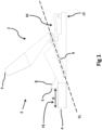
- a distance between the front part of the lower jaw part and a rodent accommodating element substantially perpendicular to the jaw rotational axis can be for a mouse trap in a range of 10mm to 30mm, preferably 12mm to 20mm, most preferably substantially 13 to 18 mm, or for a rat trap in a range of 30mm to 50mm, preferably 33mm to 45mm, most preferably 38 to 42mm. (we refer here to "D" in figure 1 )
- the bait holding element can include a cap.
- a cap protects the bait inside the bait holding element in case the trap is not in use.
- the cap can be removed before use.
- the cap additionally can comprise one or more, preferably two, wings, being adapted to keep the lifting lever in a lifted positions. This prevents unintentional activation of the trap by disengaging the latch.
- the wings can be arranged on at least one preferably two sides of the cap, in an area of the cap, which is arranged under the lifting lever, preferably the rodent accomodating element while the cap is covering the bait holding
- the bait holding element can be part of the lower jaw part.
- the lifting lever can comprise a lever rotational axis which is preferably arranged on the second side of the jaw rotational axis.
- the latch means are preferably at least partially arranged substantially perpendicularly above or slightly beside the lever rotational axis.
- the lifting lever can comprise a substantially two-prong fork shaped end on the latch side of the lifting lever.
- This design enables an easy attachment of the lifting lever on the lower jaw part.
- the lifting lever is fixed to the lower jaw part by pushing together the two-prong fork shaped end and thereby snapping small bolts into the lower jaw part and thereby create the lever rotational axis.
- the lower jaw part can comprise a blocking element which is arranged between the two-prongs of the fork shaped and of the lifting lever to prevent the lever to release from the lower jaw part.
- the lifting lever can comprises a rotational length L rot which extends from a front of the rodent accommodating element to the rotational axis A lever of the lifting lever.
- the latch means comprise a length L latch which extends from the rotational axis A lever of lifting lever the point of the latch means where the latch means hook into the latch receiving element.
- the rotational length L rot of the lifting lever is larger than the latch length L latch to enable a small movement of the lifting lever.
- the upper jaw part can comprise an opening or dormer-shaped element to allow for more space for the rodent accommodating element.
- the object of the invention is further accomplished by a system for refilling a rodent trap as previously described comprising a syringe with bait refill.
- the syringe with a bait refill is an optimal method for refilling the bait holding element inside the rodent trap.
- the bait used is peanut butter.
- the use of the syringe enables a refilling of the bait holding element along its entire length and underneath the rodent accommodating element without endangering fingers to be trapped accidentally.
- the object of the invention is further accomplished by a method of refilling a rodent trap as previously described, in which the rodent trap is arranged in the open position and the bait is refilled, preferably into the bait holding element, using a syringe comprising bait, preferably peanut butter.
- the object of the invention is further achieved by a method of catching and preferably killing a rodent comprising the step of positioning a rodent trap as previously described on a surface and putting the rodent trap into the open position.
- the bait holding element preferably extends along a direction perpendicular to the jaw rotational axis, called bait holder length, longer than in the direction parallel to the jaw rotational axis, called bait holder width.
- the bait holder length is at least three times, more preferably four times, larger than the bait holder width.
- bait holding element basically leads the rodent into the rodent accommodating element.
- bait holding element can comprise rounded corners inside the rodent accommodating element to optimally position the bait holding element beneath the rodent accommodating element.
- Figure 2 is a longitudinal section of the rodent trap 1 according to figure 1 .
- the latch means 7 and the bait holding element 10 are visible.
- the latch means 7 engage latch receiving element 9 in the upper jaw part 3.
- a funnel shaped rodent accommodating element 8 is additionally shown.
- the bait holding element 10 is partly arranged beneath the funnel shaped element 8 and extends beyond the funnel shaped rodent accommodating element 8 to entice a rodent into the trap.
- the force means 6 is arranged in the two force means slots of the upper jaw part 3 and the lower jaw part 4 respectively. To open the trap 1 and put the upper jaw part 3 into an open position, the user has to push down activating lever 14 into the direction of the lower jaw part 4.
- Figure 6 shows a perspective view of the rodent trap 1 without showing the upper jaw part 3.
- the first length L1 of a lifting lever 5 is larger than the second length L2 of lifting lever 5.
- the lever rotational axis A lever is arranged in parallel to the jaw rotational axis A jaw .
- the latch means 7 are arranged close to the lever rotational axis A lever such that the distance the lifting lever 5 needs to be moved at the rodent accommodating element 8 is larger than the distance the latch means 7 needs to move to activate the trap.
- FIG 9 shows an alternative embodiment to the trap in Figure 1 differing from the embodiment of figure 1 in the design of the lifting lever 5 and the design of the upper jaw part 3.
- the upper jaw part 3 comprises a dormer-shaped element 20.
- the dormer-shaped element 20 allows for a larger rodent accommodating element 8 while the trap 1 still can be as small as possible.
- the lifting lever 5 comprises a fixing element 17 being arranged at the lever rotational axis A lever .
- the fixing element 17 is arranged in a slot 18.
- the slot 18 comprises two holding elements 19.
- the fixing element 17 has a rectangular shape (see Figure 10 ). In a mounted position as shown in Figure 9 the fixing element 17 is kept in the slot 18 by two holding elements 19. Nevertheless, the lifting lever 5 can be rotated around lever rotational axis A lever
Landscapes
- Life Sciences & Earth Sciences (AREA)
- Pest Control & Pesticides (AREA)
- Engineering & Computer Science (AREA)
- Insects & Arthropods (AREA)
- Wood Science & Technology (AREA)
- Zoology (AREA)
- Environmental Sciences (AREA)
- Catching Or Destruction (AREA)
Description
- The invention concerns a rodent trap and corresponding methods.
- Generally, rodent traps for catching and killing rodents are known from the prior art. There are traps such as the trap disclosed in
US 4,991,340 which comprises two jaws which are closed when a rodent steps on a trigger. Those kinds of mouse traps have the disadvantage that they can close accidentally and even catch birds when they step on the trigger. -
WO 2005/099451 discloses an animal trap comprising a complicated mechanism to trigger a shackle killing the animal. Such a complicated mechanism is costly to produce and very sensitive to outer influences when the trap is moved or touched by other animals. Further relevant state of the art documents are for example:US 9 210 924 B1 US 5 960 583 A ,WO 03/063588 A1 - It is therefore the object of the present invention to create a mouse trap which overcomes the disadvantages of the prior art and in particular create a mouse trap which is easy to produce and safe and reliable in use and more effective and human in killing.
- The object is achieved by the independent claims. The object is particularly achieved by a rodent trap for catching and killing rodents, in particular mice and/or rats comprising the features of
claims 1 to 16. - Such a rodent trap is safe to use and efficient in killing the animals and cheap to produce.
- The upper jaw part can swing from an open position to a closed position and preferably it can swing back from a closed position to an open position. The swinging from a closed to an open position requires an opening force, hence against the force means, the swinging to the closed position is actuated by the force means.
- Preferably the lifting lever is a one piece lever, interacting directly with the clamp means. No further levers are arranged between the lifting lever and the clamp means. The force means preferably comprises exactly one spring. The force means can alternatively comprise more than one spring, such as two or more. Preferably, the rodent trap is made entirely from plastic material, except the force means which also can be a metal material. In case of a force means in form of a spring, the spring can be a metal or non-metal garter spring or alternatively a metal spiral spring or a rubber spring or a rubber band.
- The lifting lever preferably is only activatable by being lifted upwards, in particular away from the lower jaw part of the trap.
- This way the trap can only be activated when intentionally lifting the lever and thereby accidental stepping on the trigger by other animals does not lead to activating the trap.
- In that case the lower jaw part preferably comprises a base floor and an edge. The lifting lever preferably lifts away from the base plate of the lower jaw part.
- The lifting lever can comprise a rodent accommodating element, in particular having at least partially a rounded shape, arranged opposite of the latch side.
- The rodent accommodating element leads to guiding the rodent into the right position for activating the trap. For that purpose the rodent accommodating element is adapted to the head of a rodent and has preferably at least partially a rounded shape. Alternatively, the rodent accommodating element can also be triangular or square. Furthermore, the rodent accommodating element preferably is funnel shaped such that the rodent easily fits into the rodent accommodating element.
- The force means can exert a closing force on the upper jaw part and the lower jaw part in the closed position such that both jaws are pressed against each other. In particular, a longitudinal centerline of the force means is located beside the jaw rotational axis, preferably located on the first side of the jaw rotational axis.
- This way the strongest force is exerted on the jaw parts when they are closed. The longitudinal centreline of the force means is the direction of force of the force means. The longitudinal centerline is substantially perpendicular to the jaw rotational axis. The longitudinal centerline of the force means is located closer to the jaw rotational axis when the clamp means is in the open position. When the clamp means is in the closed position, the longitudinal centerline is farther away from the jaw rotational axis compared to the open position, providing a bigger clamping force.
- The force means can exert a lower force on the upper and the lower jaw part in the open position than in the closed position. The force means in particular exerts substantially close to no force in the open position compared to the closed position. Preferably, the longitudinal centreline of the force means is aligned with the jaw rotational axis or located slightly on the first side of the jaw rotational axis in the opened position.
- Slightly in this context means that a distance between the jaw rotational axis and the longitudinal centreline perpendicular to the jaw rotational axis is smaller than a third of the length of the lifting lever, preferably smaller than the second length of the lifting lever.
- A first length of the lifting lever on the first side of the jaw rotational axis can be longer than a second length of the lifting lever on the second side of the jaw rotational axis.
- This way the movement needed by the rodent to lift the lever is bigger compared to the distance needed to unlock the latch on the second side of the lifting lever. This enhances the security of the trap.
- The upper jaw part can comprise a latch receiving element to be latched in the opened position by the latch means.
- This way the trap is easily fixed in the open position and easily released when needed by the lifting lever.
- A bait holding element can be arranged in the vicinity of the lifting lever, preferably at least partially underneath the lifting lever, in particular beneath the rodent accommodating element, wherein preferably the bait holding element extends from beneath the rodent accommodating element to a substantially a front part of the lower jaw part.
- The use of bait holding element in the vicinity of the lifting lever entices the rodent into the trap and to the lifting lever. In case the bait holding element extends from beneath the rodent accommodating element to substantially front part of the lower jaw part, a rodent can eat part of the bait without being in danger and without being caught. This way the rodents lose their cautiousness and the probability of catching the rodent and killing it instantly is increased.
- The front part of the lower jaw part preferably is an edge arranged on a base part of the lower jaw part. In case both jaw parts have edges that extend above their respective basis closing of the trap leads to a directed hit onto the neck and thereby instant death of the rodent. The edge can be a rounded edge or a toothed edge or a combinations thereof.
- A distance between the front part of the lower jaw part and a rodent accommodating element substantially perpendicular to the jaw rotational axis can be for a mouse trap in a range of 10mm to 30mm, preferably 12mm to 20mm, most preferably substantially 13 to 18 mm, or for a rat trap in a range of 30mm to 50mm, preferably 33mm to 45mm, most preferably 38 to 42mm. (we refer here to "D" in
figure 1 ) - Depending on the rodent to catch those distances lead to the perfect positioning of the front part of the lower jaw part and the front part of the upper jaw part in the area of the neck of the rodent when the rodent is enticed by the bait into the rodent accommodating element. This way the rodent dies quickly and painless.
- The bait holding element can include a cap.
- A cap protects the bait inside the bait holding element in case the trap is not in use. The cap can be removed before use. The cap additionally can comprise one or more, preferably two, wings, being adapted to keep the lifting lever in a lifted positions. This prevents unintentional activation of the trap by disengaging the latch. The wings can be arranged on at least one preferably two sides of the cap, in an area of the cap, which is arranged under the lifting lever, preferably the rodent accomodating element while the cap is covering the bait holding The bait holding element can be part of the lower jaw part.
- This way the bait holding element is fixed on the lower jaw part or even a structural part of the lower jaw part and thereby is easily refillable.
- The lifting lever can comprise a lever rotational axis which is preferably arranged on the second side of the jaw rotational axis. The latch means are preferably at least partially arranged substantially perpendicularly above or slightly beside the lever rotational axis.
- Such an arrangement leads to optimal lever relations and thereby to secure opening and releasing of the latch when the rodent is inside the rodent accommodating element and lifts the lever.
- The lifting lever can comprise a substantially two-prong fork shaped end on the latch side of the lifting lever.
- This design enables an easy attachment of the lifting lever on the lower jaw part. The lifting lever is fixed to the lower jaw part by pushing together the two-prong fork shaped end and thereby snapping small bolts into the lower jaw part and thereby create the lever rotational axis.
- The lower jaw part can comprise a blocking element which is arranged between the two-prongs of the fork shaped and of the lifting lever to prevent the lever to release from the lower jaw part.
- This way the lever can easily be connected with the lower jaw part but is fixed in his position after attaching it to the lower jaw part. Furthermore, the use of the blocking element is a very cheap and secure way to secure the lifting lever.
- The lifting lever can comprise a fixing element being arranged at the lever rotational axis, wherein the fixing element is arranged in a slot. The slot preferably comprises at least one holding element.
- The fixing element fixes the lifting lever on the lower jaw part of the rodent trap, but is nevertheless rotatable in the slot. Preferably, the fixing element has a rectangular cross section. The sides extending along the length of the lifting lever are longer than the sides than the sides perpendicular to the length of the lifting lever. The holding element is arranged such that the lever is fixed in the slot when in an assembled state.
- This way the lifting lever can easily be assembled and is securely fixed in its position.
- The lifting lever can have a length of 3cm to 7cm, in particular substantially 4cm to 6cm for mouse trap and has a a length of 8 to 13 cm, in particular substantially 9 to 11 cm for rat trap.
- Such a lifting lever leads to an optimal distance to lift the lever before the latches released and optimum distance between rodent accommodating element of the lifting lever and front part or edge of the lower jaw part. The rodent accommodating element is part of the lever and therefore included in the length of the lever.
- The lifting lever can comprises a rotational length Lrot which extends from a front of the rodent accommodating element to the rotational axis Alever of the lifting lever. The latch means comprise a length Llatch which extends from the rotational axis Alever of lifting lever the point of the latch means where the latch means hook into the latch receiving element. The rotational length Lrot of the lifting lever is larger than the latch length Llatch to enable a small movement of the lifting lever.
- This enable as reliable and quick activation of the trap.
- The upper jaw part can comprise an opening or dormer-shaped element to allow for more space for the rodent accommodating element.
- This has the advantage that the trap can be as small as possible and nevertheless the rodent accommodating element can have a perfect size of the respective rodent.
- The object of the invention is further accomplished by a system for refilling a rodent trap as previously described comprising a syringe with bait refill.
- The syringe with a bait refill is an optimal method for refilling the bait holding element inside the rodent trap. Preferably, the bait used is peanut butter. Furthermore, due to the special shape of the bait holding element, the use of the syringe enables a refilling of the bait holding element along its entire length and underneath the rodent accommodating element without endangering fingers to be trapped accidentally.
- The object of the invention is further accomplished by a method of refilling a rodent trap as previously described, in which the rodent trap is arranged in the open position and the bait is refilled, preferably into the bait holding element, using a syringe comprising bait, preferably peanut butter.
- The advantages of the system similarly apply to the method.
- The object of the invention is further achieved by a method of catching and preferably killing a rodent comprising the step of positioning a rodent trap as previously described on a surface and putting the rodent trap into the open position.
- Such a method reliably and quickly catches and kills a rodent and thereby is an animal friendly way of catching and killing rodents.
- The bait holding element preferably extends along a direction perpendicular to the jaw rotational axis, called bait holder length, longer than in the direction parallel to the jaw rotational axis, called bait holder width. Preferably the bait holder length is at least three times, more preferably four times, larger than the bait holder width. This way the bait holding element basically leads the rodent into the rodent accommodating element. Furthermore, bait holding element can comprise rounded corners inside the rodent accommodating element to optimally position the bait holding element beneath the rodent accommodating element.
- The invention is further described by means of figures in the following. It shows:
- Figure 1:
- A side view of a rodent trap according to the invention,
- Figure 2:
- a longitudinal section to a rodent trap according to
figure 1 , - Figure 3:
- a perspective view of a rodent trap according to
figure 1 in the open position, - Figur3 4:
- an alternative embodiment of a rodent trap according to the invention in the perspective view,
- Figure 5:
- an alternative embodiment of a trap according to
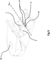
figure 4 , - Figure 6:
- a perspective view of a trap according to the invention without upper jaw part,
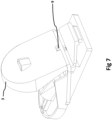
- Figure 7:
- a perspective view of a trap according to the invention from the back side in the open position,
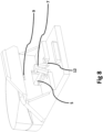
- Figure 8:
- a perspective view of the trap according to the invention from the back side in a closed position,
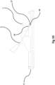
- Figure 9:
- a perspective view of the trap according to the invention in a closed position,
- Figure 10:
- a cross sectional view of the trap according to
figure 9 . -
Figure 1 shows arodent trap 1 in the open position. Therodent trap 1 comprises clamp means 2. The clamp means 2 comprise anupper jaw part 3 and alower jaw part 4. In the open position, theupper jaw part 3 is lifted away from thelower jaw part 4. Bothjaw parts jaw part rodent trap 1lifting lever 5 is arranged to release the latch means (not shown) which keeps theupper jaw part 3 in the open position, when a rodent is inside the trap. When the upper jaw part is released from the latch means (not shown) force means 6 in form of a single garter spring, forces theupper jaw part 3 into the direction to thelower jaw part 4 such that the front ends of both jaw parts are moved to each other. The force means 6 have a longitudinal centreline CL which is arranged substantially perpendicular to a jaw rotational axis Ajaw seefigure 3 . The liftinglever 5 comprises rodentaccommodating element 8 which has a funnel shaped opening for accommodating the nose of a rodent. The liftinglever 5 is activatable by a rodent on a first side FS of the jaw rotational axis Ajaw (seefigure 3 ). The latch means 7 are arranged on a latch side LS of the liftinglever 5 and are arranged on the second side SS of the jaw rotational axis Ajaw (seefigure 3 ). The second side SS is arranged opposite of the first side FS of the jaw rotational axis. The distance D between rodentaccommodating element 8 and front side of thelower jaw part 4 is substantially 15mm for a mouse trap and substantially 40mm for a rat trap. Apart from the force means 6, which is a garter spring, the rodent trap is made from plastic material to accommodate the force means 6 in the rodent trap theupper jaw part 3 and thelower jaw part 4 comprise spring grooves. The spring grooves are arranged such that the force of the force means 6 is distributed optimally. -
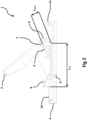
Figure 2 is a longitudinal section of therodent trap 1 according tofigure 1 . In the section additional to the features already shown infigure 1 , the latch means 7 and thebait holding element 10 are visible. The latch means 7 engagelatch receiving element 9 in theupper jaw part 3. A funnel shaped rodentaccommodating element 8 is additionally shown. Thebait holding element 10 is partly arranged beneath the funnel shapedelement 8 and extends beyond the funnel shaped rodentaccommodating element 8 to entice a rodent into the trap. The force means 6 is arranged in the two force means slots of theupper jaw part 3 and thelower jaw part 4 respectively. To open thetrap 1 and put theupper jaw part 3 into an open position, the user has to push down activatinglever 14 into the direction of thelower jaw part 4. Theupper jaw part 3 then swings around the jaw rotational axis Ajaw (seefigure 3 ) into the open position. When the latch means 7 are released, theupper jaw part 3 swings back around the jaw rotational axis Ajaw into the closed position. The liftinglever 5 comprises a rotational length Lrot which extends from the front of the rodentaccommodating element 8 to the rotational axis Alever of the liftinglever 5. The latch means 7 comprise a length Llatch which extends from the rotational axis Alever of liftinglever 5 the point of the latch means 7 where to latch means hook into thelatch receiving element 9. The rotational length Lrot of liftinglever 5 is larger than the latch length Llatch to enable a small movement of the liftinglever 5. -
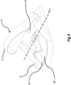
Figure 3 shows a perspective view of arodent trap 1 according to the invention in an open position. Theupper jaw part 3 swings around jaw rotational axis Ajaw from an open into a closed position and vice versa. To activate therodent trap 1 the user has to push down activatinglever 14. A first length of L1 of the liftinglever 5 which is the length of the lever between a jaw rotational axis Ajaw and front of rodentaccommodating element 8 is larger than a second length L2 (seefigure 6 ) of liftinglever 5 arranged between jaw rotational axis Ajaw and end of the two-prong fork shapedend 12 of the lifting lever 5 (seefigure 6 ). The two prongs of two-prong fork shapedend 12 and kept away from each other in by blockingelement 13. -
Figure 4 shows an alternative embodiment of therodent trap 1 offigure 3 in the open position. In this embodiment thebait holding element 10 is covered by acap 11 to keep the bait fresh. Thecap 11 extends beyond thelower jaw part 4 and comprises a handle to easily remove thecap 11. This leads to a visibility to a user even in the closed state of thetrap 1 that the bait is still covered by a cover. Furthermore, in this perspective the two-prong fork shapedend 12 of the liftinglever 5 is visible. Between the two prongs of the two-prong fork shapedend 12 blockingelement 13 is arranged to keep the prongs apart as soon as the liftinglever 5 is arranged on thelower jaw part 4. Furthermore, in this figure thelatch receiving element 9 of upper jaw part is visible. All of the features correspond to the previous figures. -
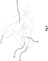
Figure 5 shows an alternative embodiment of thecap 11 without handle. Still thecap 11 extends beyond thefront part 15 of thelower jaw part 4. This leads to a visibility to a user even in the closed state of thetrap 1 that the bait is still covered by a cover. Furthermore, in this perspective the two-prong fork shapedend 12 of the liftinglever 5 is visible. Between the two prongs of thefork blocking element 13 is arranged to keep the prongs apart as soon as the liftinglever 5 it arranged on thelower jaw part 4.Wings 16 are provided on thecap 11 to keep the lifting element in a lifted position when the cap is on the bait holding element. -
Figure 6 shows a perspective view of therodent trap 1 without showing theupper jaw part 3. The first length L1 of a liftinglever 5 is larger than the second length L2 of liftinglever 5. The lever rotational axis Alever is arranged in parallel to the jaw rotational axis Ajaw. The latch means 7 are arranged close to the lever rotational axis Alever such that the distance the liftinglever 5 needs to be moved at the rodentaccommodating element 8 is larger than the distance the latch means 7 needs to move to activate the trap. -
Figure 7 shows a back side view of thetrap 1 according to the invention. Thelatch receiving element 9 ofupper jaw part 3 is explicitly visible. All other features correspond to the previous figures. -
Figure 8 shows the back side view of thetrap 1 in a closed position. The latch means 7 is not connected to alatch receiving element 9. Additionally, the two-prong fork shapedend 12 of liftinglever 5 is clearly visible. All other features correspond to the previous figures. -
Figure 9 shows an alternative embodiment to the trap inFigure 1 differing from the embodiment offigure 1 in the design of the liftinglever 5 and the design of theupper jaw part 3. Theupper jaw part 3 comprises a dormer-shapedelement 20. The dormer-shapedelement 20 allows for a larger rodentaccommodating element 8 while thetrap 1 still can be as small as possible. The liftinglever 5 comprises a fixingelement 17 being arranged at the lever rotational axis Alever. The fixingelement 17 is arranged in aslot 18. Theslot 18 comprises two holdingelements 19. The fixingelement 17 has a rectangular shape (seeFigure 10 ). In a mounted position as shown inFigure 9 the fixingelement 17 is kept in theslot 18 by two holdingelements 19. Nevertheless, the liftinglever 5 can be rotated around lever rotational axis Alever -
Figure 10 show a cross section of the liftinglever 5 and thelower jaw part 4. The fixingelement 17 has a rectangular shape, while the longer sides of the rectangle are parallel to the lever length. the shorter sides of the rectangle are perpendicular to the lever length. When assembling thetrap 1 the liftinglever 5 is brought in a position substantially perpendicular to thelower jaw part 4 and the fixingelement 17 is inserted into theslot 18. The liftinglever 5 is then brought to the mouted position in thelower jaw 4 such that the fixingelement 17 is fixed in theslot 18 by holdingelements 19. The liftinglever 5 is thus fixed in theslot 18.
Claims (18)
- Rodent trap (1) for catching and killing rodents, in particular mice and/or rats, comprisingclamp means (2) at least having an upper jaw part (3) and a lower jaw part (4) , wherein the upper jaw part (3) is able to swing relative to the lower jaw part (4) from an open position to a closed position, in which it hits and kills a rodent,the upper jaw part (3) being at least partially rotatable around a jaw rotational axis (Ajaw)a lifting lever (5) for releasing the clamp means (2) from the open position, the lifting lever (5) being activatable by a rodent on a first side (f) of the jaw rotational axis (Ajaw),a force means (6), in particular at least one spring, enabling the clamp means (2) to change from the open position into the closed position when released,the lifting lever (5) comprising a latch means (7) on a latch side (LS)of the lifting lever(5) being arranged on a second side (SS) of the jaw rotational axis (Ajaw), opposite of the first side (FS) of the jaw rotational axis (Ajaw),characterized in that the force means (6) in the closed position exerts a closing force on the upper jaw part (3) and the lower jaw part (4) such that both jaws (3,4) are pressed against each other, wherein a longitudinal centerline (CL) of the force means (6) is located beside the jaw rotational axis (Ajaw), preferably located on the first side (FS) of the jaw rotational axis (Ajaw).
- Rodent trap (1) according to claim 1, characterized in that the lifting lever (5) is only activatable by being lifted upwards, in particular away from the lower jaw part (4) of the trap (1).
- Rodent trap (1) according to any one of the preceding claims, characterized in that the lifting lever (5) comprises a rodent accommodating element (8), in particular having at least partially a rounded shape, arranged opposite of the latch side (LS).
- Rodent trap (1) according to any one of the preceding claims, characterized in that the force means (6) in the open position exerts a lower force on the upper (3) and the lower jaw part (4) than in the closed position, in particular substantially close to no force, wherein preferably the longitudinal centerline (CL) of the force means (6) is aligned with the jaw rotational axis (Ajaw) or located slightly on the first side (FS) of the jaw rotational axis (Ajaw).
- Rodent trap (1) according to any one of the preceding claims characterized in that a first length (L1) of the lifting lever (5) on first side (f) of the jaw rotational axis (Ajaw) is longer than a second length (L2) of the lifting lever (5) on the second side (s) of the jaw rotational axis (Ajaw).
- Rodent trap (1) according to any one of the preceding claims characterized in that the upper jaw part (3) comprises a latch receiving element (9) to be latched in the open position by the latch means (7).
- Rodent trap(1) according to any one of the preceding claims characterized in that a rotational length (Lrot) of the lifting lever (5) is longer than a latch length (Llatch) of the latch means (7).
- Rodent trap (1) according to any one of the preceding claims, characterized in that a bait holding element (10) is arranged in the vicinity of the lifting lever (5), preferably at least partially underneath the lifting lever (5), in particular beneath the rodent accomodating element (8), wherein preferably the bait holding element (10) extends from beneath the rodent accommodating element (8) to substantially a front part (15) of the lower jaw part (4).
- Rodent trap (1) according to claim 8, characterized in that a distance between the front part of the lower jaw part (4) and the rodent accommodating element (8) substantially perpendicular to the jaw rotational axis (Ajaw) is for a mouse trap in a range of 10 mm to 30 mm, preferably 12 to 20 mm, most preferably substantially 13 to 18 mm or for a rat trap in a range of 30 mm to 50 mm, preferably 33 mm to 45 mm, most preferably 38 mm to 42 mm.
- Rodent trap (1) according to any one of claims 8 to 9 characterized in that the bait holding element (10) includes a cap (11).
- Rodent trap (1) according to any one of claims 7 to 9 characterized in that the bait holding element (10) is part of the lower jaw part (4).
- Rodent trap (1) according to any one of the preceding claims, characterized in that the lifting lever (5) comprises a lever rotational axis (Alever)which is preferably arranged on the second side (s) of the jaw rotational axis (Ajaw), wherein the latch means (7) are preferably arranged at least partially substantially perpendicularly above or slightly beside the lever rotational axis.
- Rodent trap (1) according to any one of the preceding claims, characterized in that the lifting lever (5) comprises a substantially two-prong fork shaped end (12) on the latch side (L) of the lifting lever (5).
- Rodent trap (1) according to claim 13, characterized in that the lower jaw part (4) comprises a blocking element (13) which is arranged between the two prongs of the fork shaped end (12) of the lifting lever (5) to prevent the lever to release from the lower jaw part (4).
- Rodent trap (1) according to any one of claims 1 to 12, characterized in that the lifting lever (5) comprises a fixing element (17) being arranged at the lever rotational axis (Alever), wherein the fixing element (17) is arranged in a slot (18), wherein the slot (18) preferably comprises at least one holding element (19).
- Rodent trap (1) according to any one of the preceding claims characterized in that the lifting lever (5) has a length of 3 to 7 cm, in particular substantially 4 to 6 cm for mouse trap and has a a length of 8 to 13 cm, in particular substantially 9 to 11 cm for rat trap.
- Method of refilling a rodent trap (1) according to any one of claims 1 to 16, characterized in that the rodent trap (1) is arranged in the open position and the bait is refilled, preferably into a bait holding element (10), using a syringe comprising bait, preferably peanut butter.
- Method of catching and preferably killing a rodent comprising the step of positioning a rodent trap (1) according to any one of claims 1 to 16 on a surface and putting the rodent trap (1) into the open position.
Applications Claiming Priority (1)
| Application Number | Priority Date | Filing Date | Title |
|---|---|---|---|
| PCT/EP2018/067888 WO2020007448A1 (en) | 2018-07-03 | 2018-07-03 | Rodent trap, system for refilling a rodent trap and method of refilling a rodent trap |
Publications (3)
| Publication Number | Publication Date |
|---|---|
| EP3836784A1 EP3836784A1 (en) | 2021-06-23 |
| EP3836784C0 EP3836784C0 (en) | 2025-04-16 |
| EP3836784B1 true EP3836784B1 (en) | 2025-04-16 |
Family
ID=62981172
Family Applications (1)
| Application Number | Title | Priority Date | Filing Date |
|---|---|---|---|
| EP18743412.1A Active EP3836784B1 (en) | 2018-07-03 | 2018-07-03 | Rodent trap and methods |
Country Status (7)
| Country | Link |
|---|---|
| US (1) | US12171213B2 (en) |
| EP (1) | EP3836784B1 (en) |
| JP (1) | JP7122479B2 (en) |
| AU (1) | AU2018431310B2 (en) |
| CA (1) | CA3115567A1 (en) |
| RU (1) | RU2766704C1 (en) |
| WO (1) | WO2020007448A1 (en) |
Families Citing this family (3)
| Publication number | Priority date | Publication date | Assignee | Title |
|---|---|---|---|---|
| DK180462B1 (en) * | 2019-07-05 | 2021-05-06 | Anticimex Innovation Center As | Rodent trap |
| US11477979B2 (en) | 2019-10-01 | 2022-10-25 | Woodstream Corporation | Snap trap with set-prevent interference member and rodent orienting side walls |
| WO2023110060A1 (en) * | 2021-12-14 | 2023-06-22 | Swissinno Solutions Ag | A trap for rodents and method of catching and preferably killing a rodent |
Citations (3)
| Publication number | Priority date | Publication date | Assignee | Title |
|---|---|---|---|---|
| US5960583A (en) | 1995-06-21 | 1999-10-05 | Hansson; Goeran | Trap for catching and killing of small animals |
| WO2003063588A1 (en) | 2002-01-28 | 2003-08-07 | Vangus Ab | Trap |
| US9210924B1 (en) | 2012-03-27 | 2015-12-15 | Ty Terrell | Ecofriendly maritime pest management kit |
Family Cites Families (12)
| Publication number | Priority date | Publication date | Assignee | Title |
|---|---|---|---|---|
| US2637931A (en) * | 1951-01-16 | 1953-05-12 | Nathan R Sklar | Latching and releasing means |
| US4468883A (en) * | 1982-04-19 | 1984-09-04 | Environmentally Safe Products, Corp. | Mouse trap |
| US4991340A (en) | 1990-03-23 | 1991-02-12 | Schildt Walter C | Animal trap |
| US6508031B1 (en) * | 2001-10-26 | 2003-01-21 | Bell Laboratories, Inc. | Rodent trap with removable bait container |
| BR0311434A (en) | 2002-05-07 | 2005-03-22 | Bayer Cropscience Ag | Rodenticide bait systems |
| SE527605C2 (en) | 2004-04-14 | 2006-04-25 | Per Danielsson | Trap for animals |
| RU51826U1 (en) * | 2005-05-11 | 2006-03-10 | Государственное научное учреждение Ставропольский научно-исследовательский институт животноводства и кормопроизводства | MOBILE ROD TRAP-KAPPAN |
| US20100257773A1 (en) * | 2009-04-13 | 2010-10-14 | O'dell Jim | Mousetrap |
| ITTO20130497A1 (en) * | 2013-06-17 | 2014-12-18 | Thomas Pecoraro | TRAP FOR CATCHING ANIMALS, IN PARTICULAR FOR MURIDES |
| US20160029616A1 (en) * | 2014-08-01 | 2016-02-04 | Brandon Johnston | Pest deterrent barrier |
| WO2017188828A1 (en) * | 2016-04-29 | 2017-11-02 | Nz Autotraps Limited | Improvements to traps and / or bait dispensing apparatus |
| US11178864B2 (en) * | 2017-04-28 | 2021-11-23 | Ron Petrous | Pre-loaded bait rodent trap |
-
2018
- 2018-07-03 US US17/276,584 patent/US12171213B2/en active Active
- 2018-07-03 CA CA3115567A patent/CA3115567A1/en active Pending
- 2018-07-03 EP EP18743412.1A patent/EP3836784B1/en active Active
- 2018-07-03 AU AU2018431310A patent/AU2018431310B2/en active Active
- 2018-07-03 JP JP2021546044A patent/JP7122479B2/en active Active
- 2018-07-03 WO PCT/EP2018/067888 patent/WO2020007448A1/en not_active Ceased
- 2018-07-03 RU RU2021106328A patent/RU2766704C1/en active
Patent Citations (3)
| Publication number | Priority date | Publication date | Assignee | Title |
|---|---|---|---|---|
| US5960583A (en) | 1995-06-21 | 1999-10-05 | Hansson; Goeran | Trap for catching and killing of small animals |
| WO2003063588A1 (en) | 2002-01-28 | 2003-08-07 | Vangus Ab | Trap |
| US9210924B1 (en) | 2012-03-27 | 2015-12-15 | Ty Terrell | Ecofriendly maritime pest management kit |
Non-Patent Citations (24)
| Title |
|---|
| D4.1 - Technische Zeichnung „Mausefalle_n_Auslöser" der S. Franzen Söhne GmbH vom 7. November 2011, Projektnummer 1704 |
| D4.10 - Speditionsübergabeschein an die REWE-Zentral AG vom 30. September 2014 |
| D4.11 - Zahlungsnachweis der REWE-Zentral AG vom 24. Oktober 2014, betreffend die Rechnung gemäß dem Dokument D4.5 |
| D4.12 - Auftragsbestätigung vom 14. Oktober 2014 der S. Franzen Söhne GmbH an die BAUHERR Gartengeräte & Bauwerkzeuge GmbH, Franzen Artikel Nr. 0170401012 |
| D4.13 - Rechnung vom 13. November 2014 der S. Franzen Söhne GmbH an die BAUHERR Gartengeräte & Bauwerkzeuge GmbH, Franzen Artikel Nr. 0170401012 |
| D4.14 - Lieferschein vom 11. November 2014 der S. Franzen Söhne GmbH an die BAUHERR Gartengeräte & Bauwerkzeuge GmbH, Franzen Artikel Nr. 0170401012 |
| D4.15 - Speditionsübergabeschein an die BAUHERR Gartengeräte & Bauwerkzeuge vom 12. November |
| D4.16 - Kontoauszug der S. Franzen Söhne GmbH betreffend Zahlungsnachweis der Rechnung 384480 gemäß dem Dokument D4.9 |
| D4.17 - Auftragsbestätigung vom 13. Juli 2016 der S. Franzen Söhne GmbH an die Bauherr GmbH, Franzen Artikel Nr. 4000021 |
| D4.18 - Rechnung vom 11. August 2016 der S. Franzen Söhne GmbH an die Bauherr GmbH, Franzen Artikel Nr. 4000021 |
| D4.19 - Lieferschein vom 11. August 2016 der S. Franzen Söhne GmbH an die Bauherr GmbH, Franzen Artikel Nr. 4000021 |
| D4.2 - Technische Zeichnung in Übereinstimmung mit der Darstellung gemäß D4.1, mit zu der EP 3 836 784 B1 korrespondierenden Bezugszeichen |
| D4.20 - Auftragsbestätigung vom 8. Mai 2018 der S. Franzen Söhne GmbH an die Rewe-Zentral-AG, Franzen Artikel Nr. 4000024 |
| D4.21 - Rechnung vom 28. Mai 2018 der S. Franzen Söhne GmbH an die Rewe-Zentral-AG, Franzen Artikel Nr. 4000024 |
| D4.22 - Lieferschein vom 23. Mai 2018 der S. Franzen Söhne GmbH an die Rewe-Zentral-AG, Franzen Artikel Nr. 4000024 |
| D4.23 - Eidesstattliche Versicherung des Herrn Tobias Ackermann |
| D4.24 - EIDESSTATTLICHE VERSICHERUNG DES HERRN LARS WAGENER |
| D4.3 - Fotodarstellungen der Mausefalle in Übereinstimmung mit der im Dokument D4.1/D4.2 dargestellten technischen Zeichnung |
| D4.4 - Verkaufskarte für die in den Dokumenten D4.1 bis D4.3 gezeigte Mausefalle – Vorderseite |
| D4.5 - Verkaufskarte für die in den Dokumenten D4.1 bis D4.3 gezeigten Mausefallen – Rückseite |
| D4.6 - Verkaufsanordnung von Mausefallen auf Verkaufskarte (2er Pack) |
| D4.7 - Auftragsbestätigung vom 29. September 2014 der S. Franzen Söhne GmbH an die REWE-Zentral AG, Franzen Artikel Nr. 0170401012 |
| D4.8 - Rechnung vom 30. September 2014 der S. Franzen Söhne GmbH an die REWE-Zentral AG, Franzen Artikel Nr. 0170401012 |
| D4.9 - Lieferschein vom 30. September 2014 der S. Franzen Söhne GmbH an die REWE-Zentral AG, Franzen Artikel Nr. 0170401012 |
Also Published As
| Publication number | Publication date |
|---|---|
| AU2018431310A1 (en) | 2021-04-08 |
| AU2018431310B2 (en) | 2024-09-19 |
| WO2020007448A1 (en) | 2020-01-09 |
| EP3836784C0 (en) | 2025-04-16 |
| JP7122479B2 (en) | 2022-08-19 |
| US20240000061A1 (en) | 2024-01-04 |
| JP2021533836A (en) | 2021-12-09 |
| CA3115567A1 (en) | 2020-01-09 |
| RU2766704C1 (en) | 2022-03-15 |
| EP3836784A1 (en) | 2021-06-23 |
| US12171213B2 (en) | 2024-12-24 |
| BR112021005181A2 (en) | 2021-06-29 |
Similar Documents
| Publication | Publication Date | Title |
|---|---|---|
| EP3836784B1 (en) | Rodent trap and methods | |
| EP2312942B1 (en) | Rodent trap having a pivoting platform | |
| CA1093301A (en) | Self-locking disposable rodent trap | |
| US9545095B2 (en) | Apparatus, method and kit for extermination of pests | |
| US4583317A (en) | Animal trap | |
| US11477979B2 (en) | Snap trap with set-prevent interference member and rodent orienting side walls | |
| CA2709275C (en) | Rodent trap having a pivoting platform | |
| US20070289200A1 (en) | Trap for Animals | |
| US4856225A (en) | Gopher trap | |
| US20180132474A1 (en) | Mousetrap apparatus | |
| US20050274057A1 (en) | Humane leg hold trap | |
| US10051855B2 (en) | Animal trap system | |
| US9510587B1 (en) | Animal trap | |
| US1995344A (en) | Animal trap | |
| US20150033616A1 (en) | Rodent Poison Dispenser | |
| US2311378A (en) | Trap | |
| US20240407353A1 (en) | A trap for rodents and method of catching and preferably killing a rodent | |
| BR112021005181B1 (en) | RODENT TRAP FOR CATCHING AND KILLING RODENTS, IN PARTICULAR MICE AND/OR RAT, SYSTEM AND METHOD FOR RELOADING A RODENT TRAP, AND METHOD FOR CATCHING AND KILLING A RODENT | |
| US10080358B1 (en) | Animal trap | |
| US20250280818A1 (en) | Burrowing animal traps | |
| CA1289744C (en) | Humane animal trap | |
| SK6117Y1 (en) | Safety chamber mouse and rats trap | |
| ITUD990032U1 (en) | MOUSE CATCH TRAP |
Legal Events
| Date | Code | Title | Description |
|---|---|---|---|
| STAA | Information on the status of an ep patent application or granted ep patent |
Free format text: STATUS: UNKNOWN |
|
| STAA | Information on the status of an ep patent application or granted ep patent |
Free format text: STATUS: THE INTERNATIONAL PUBLICATION HAS BEEN MADE |
|
| PUAI | Public reference made under article 153(3) epc to a published international application that has entered the european phase |
Free format text: ORIGINAL CODE: 0009012 |
|
| STAA | Information on the status of an ep patent application or granted ep patent |
Free format text: STATUS: REQUEST FOR EXAMINATION WAS MADE |
|
| 17P | Request for examination filed |
Effective date: 20210421 |
|
| AK | Designated contracting states |
Kind code of ref document: A1 Designated state(s): AL AT BE BG CH CY CZ DE DK EE ES FI FR GB GR HR HU IE IS IT LI LT LU LV MC MK MT NL NO PL PT RO RS SE SI SK SM TR |
|
| DAV | Request for validation of the european patent (deleted) | ||
| GRAP | Despatch of communication of intention to grant a patent |
Free format text: ORIGINAL CODE: EPIDOSNIGR1 |
|
| STAA | Information on the status of an ep patent application or granted ep patent |
Free format text: STATUS: GRANT OF PATENT IS INTENDED |
|
| INTG | Intention to grant announced |
Effective date: 20241011 |
|
| GRAS | Grant fee paid |
Free format text: ORIGINAL CODE: EPIDOSNIGR3 |
|
| GRAA | (expected) grant |
Free format text: ORIGINAL CODE: 0009210 |
|
| STAA | Information on the status of an ep patent application or granted ep patent |
Free format text: STATUS: THE PATENT HAS BEEN GRANTED |
|
| AK | Designated contracting states |
Kind code of ref document: B1 Designated state(s): AL AT BE BG CH CY CZ DE DK EE ES FI FR GB GR HR HU IE IS IT LI LT LU LV MC MK MT NL NO PL PT RO RS SE SI SK SM TR |
|
| REG | Reference to a national code |
Ref country code: GB Ref legal event code: FG4D |
|
| REG | Reference to a national code |
Ref country code: CH Ref legal event code: EP |
|
| REG | Reference to a national code |
Ref country code: IE Ref legal event code: FG4D |
|
| REG | Reference to a national code |
Ref country code: DE Ref legal event code: R096 Ref document number: 602018081134 Country of ref document: DE |
|
| U01 | Request for unitary effect filed |
Effective date: 20250506 |
|
| U07 | Unitary effect registered |
Designated state(s): AT BE BG DE DK EE FI FR IT LT LU LV MT NL PT RO SE SI Effective date: 20250512 |
|
| PG25 | Lapsed in a contracting state [announced via postgrant information from national office to epo] |
Ref country code: ES Free format text: LAPSE BECAUSE OF FAILURE TO SUBMIT A TRANSLATION OF THE DESCRIPTION OR TO PAY THE FEE WITHIN THE PRESCRIBED TIME-LIMIT Effective date: 20250416 |
|
| PG25 | Lapsed in a contracting state [announced via postgrant information from national office to epo] |
Ref country code: NO Free format text: LAPSE BECAUSE OF FAILURE TO SUBMIT A TRANSLATION OF THE DESCRIPTION OR TO PAY THE FEE WITHIN THE PRESCRIBED TIME-LIMIT Effective date: 20250716 Ref country code: GR Free format text: LAPSE BECAUSE OF FAILURE TO SUBMIT A TRANSLATION OF THE DESCRIPTION OR TO PAY THE FEE WITHIN THE PRESCRIBED TIME-LIMIT Effective date: 20250717 |
|
| PG25 | Lapsed in a contracting state [announced via postgrant information from national office to epo] |
Ref country code: PL Free format text: LAPSE BECAUSE OF FAILURE TO SUBMIT A TRANSLATION OF THE DESCRIPTION OR TO PAY THE FEE WITHIN THE PRESCRIBED TIME-LIMIT Effective date: 20250416 |
|
| PG25 | Lapsed in a contracting state [announced via postgrant information from national office to epo] |
Ref country code: HR Free format text: LAPSE BECAUSE OF FAILURE TO SUBMIT A TRANSLATION OF THE DESCRIPTION OR TO PAY THE FEE WITHIN THE PRESCRIBED TIME-LIMIT Effective date: 20250416 |
|
| PGFP | Annual fee paid to national office [announced via postgrant information from national office to epo] |
Ref country code: CH Payment date: 20250929 Year of fee payment: 8 |
|
| PG25 | Lapsed in a contracting state [announced via postgrant information from national office to epo] |
Ref country code: RS Free format text: LAPSE BECAUSE OF FAILURE TO SUBMIT A TRANSLATION OF THE DESCRIPTION OR TO PAY THE FEE WITHIN THE PRESCRIBED TIME-LIMIT Effective date: 20250716 |
|
| PG25 | Lapsed in a contracting state [announced via postgrant information from national office to epo] |
Ref country code: IS Free format text: LAPSE BECAUSE OF FAILURE TO SUBMIT A TRANSLATION OF THE DESCRIPTION OR TO PAY THE FEE WITHIN THE PRESCRIBED TIME-LIMIT Effective date: 20250816 |
|
| PG25 | Lapsed in a contracting state [announced via postgrant information from national office to epo] |
Ref country code: SM Free format text: LAPSE BECAUSE OF FAILURE TO SUBMIT A TRANSLATION OF THE DESCRIPTION OR TO PAY THE FEE WITHIN THE PRESCRIBED TIME-LIMIT Effective date: 20250416 |
|
| PG25 | Lapsed in a contracting state [announced via postgrant information from national office to epo] |
Ref country code: CZ Free format text: LAPSE BECAUSE OF FAILURE TO SUBMIT A TRANSLATION OF THE DESCRIPTION OR TO PAY THE FEE WITHIN THE PRESCRIBED TIME-LIMIT Effective date: 20250416 |
|
| PLBI | Opposition filed |
Free format text: ORIGINAL CODE: 0009260 |
|
| PG25 | Lapsed in a contracting state [announced via postgrant information from national office to epo] |
Ref country code: SK Free format text: LAPSE BECAUSE OF FAILURE TO SUBMIT A TRANSLATION OF THE DESCRIPTION OR TO PAY THE FEE WITHIN THE PRESCRIBED TIME-LIMIT Effective date: 20250416 |
|
| REG | Reference to a national code |
Ref country code: CH Ref legal event code: L10 Free format text: ST27 STATUS EVENT CODE: U-0-0-L10-L00 (AS PROVIDED BY THE NATIONAL OFFICE) Effective date: 20260128 |
|
| PLAX | Notice of opposition and request to file observation + time limit sent |
Free format text: ORIGINAL CODE: EPIDOSNOBS2 |
|
| 26 | Opposition filed |
Opponent name: S. FRANZEN SOEHNE GMBH Effective date: 20260116 |
|
| U21 | Renewal fee for the european patent with unitary effect paid with additional fee |
Year of fee payment: 8 Effective date: 20260130 |
|
| GBPC | Gb: european patent ceased through non-payment of renewal fee |
Effective date: 20250716 |
|
| PG25 | Lapsed in a contracting state [announced via postgrant information from national office to epo] |
Ref country code: GB Free format text: LAPSE BECAUSE OF NON-PAYMENT OF DUE FEES Effective date: 20250716 |