EP3836748A1 - Internal heating trace assembly - Google Patents
Internal heating trace assembly Download PDFInfo
- Publication number
- EP3836748A1 EP3836748A1 EP20201810.7A EP20201810A EP3836748A1 EP 3836748 A1 EP3836748 A1 EP 3836748A1 EP 20201810 A EP20201810 A EP 20201810A EP 3836748 A1 EP3836748 A1 EP 3836748A1
- Authority
- EP
- European Patent Office
- Prior art keywords
- bus bar
- ceramic ptc
- internal heating
- ceramic
- heating trace
- Prior art date
- Legal status (The legal status is an assumption and is not a legal conclusion. Google has not performed a legal analysis and makes no representation as to the accuracy of the status listed.)
- Pending
Links
Images



Classifications
-
- H—ELECTRICITY
- H05—ELECTRIC TECHNIQUES NOT OTHERWISE PROVIDED FOR
- H05B—ELECTRIC HEATING; ELECTRIC LIGHT SOURCES NOT OTHERWISE PROVIDED FOR; CIRCUIT ARRANGEMENTS FOR ELECTRIC LIGHT SOURCES, IN GENERAL
- H05B3/00—Ohmic-resistance heating
- H05B3/40—Heating elements having the shape of rods or tubes
- H05B3/42—Heating elements having the shape of rods or tubes non-flexible
- H05B3/44—Heating elements having the shape of rods or tubes non-flexible heating conductor arranged within rods or tubes of insulating material
-
- B—PERFORMING OPERATIONS; TRANSPORTING
- B64—AIRCRAFT; AVIATION; COSMONAUTICS
- B64D—EQUIPMENT FOR FITTING IN OR TO AIRCRAFT; FLIGHT SUITS; PARACHUTES; ARRANGEMENT OR MOUNTING OF POWER PLANTS OR PROPULSION TRANSMISSIONS IN AIRCRAFT
- B64D15/00—De-icing or preventing icing on exterior surfaces of aircraft
- B64D15/12—De-icing or preventing icing on exterior surfaces of aircraft by electric heating
-
- F—MECHANICAL ENGINEERING; LIGHTING; HEATING; WEAPONS; BLASTING
- F16—ENGINEERING ELEMENTS AND UNITS; GENERAL MEASURES FOR PRODUCING AND MAINTAINING EFFECTIVE FUNCTIONING OF MACHINES OR INSTALLATIONS; THERMAL INSULATION IN GENERAL
- F16L—PIPES; JOINTS OR FITTINGS FOR PIPES; SUPPORTS FOR PIPES, CABLES OR PROTECTIVE TUBING; MEANS FOR THERMAL INSULATION IN GENERAL
- F16L53/00—Heating of pipes or pipe systems; Cooling of pipes or pipe systems
- F16L53/30—Heating of pipes or pipe systems
- F16L53/35—Ohmic-resistance heating
-
- H—ELECTRICITY
- H05—ELECTRIC TECHNIQUES NOT OTHERWISE PROVIDED FOR
- H05B—ELECTRIC HEATING; ELECTRIC LIGHT SOURCES NOT OTHERWISE PROVIDED FOR; CIRCUIT ARRANGEMENTS FOR ELECTRIC LIGHT SOURCES, IN GENERAL
- H05B3/00—Ohmic-resistance heating
- H05B3/10—Heating elements characterised by the composition or nature of the materials or by the arrangement of the conductor
- H05B3/12—Heating elements characterised by the composition or nature of the materials or by the arrangement of the conductor characterised by the composition or nature of the conductive material
- H05B3/14—Heating elements characterised by the composition or nature of the materials or by the arrangement of the conductor characterised by the composition or nature of the conductive material the material being non-metallic
- H05B3/141—Conductive ceramics, e.g. metal oxides, metal carbides, barium titanate, ferrites, zirconia, vitrous compounds
-
- H—ELECTRICITY
- H05—ELECTRIC TECHNIQUES NOT OTHERWISE PROVIDED FOR
- H05B—ELECTRIC HEATING; ELECTRIC LIGHT SOURCES NOT OTHERWISE PROVIDED FOR; CIRCUIT ARRANGEMENTS FOR ELECTRIC LIGHT SOURCES, IN GENERAL
- H05B3/00—Ohmic-resistance heating
- H05B3/10—Heating elements characterised by the composition or nature of the materials or by the arrangement of the conductor
- H05B3/18—Heating elements characterised by the composition or nature of the materials or by the arrangement of the conductor the conductor being embedded in an insulating material
-
- H—ELECTRICITY
- H05—ELECTRIC TECHNIQUES NOT OTHERWISE PROVIDED FOR
- H05B—ELECTRIC HEATING; ELECTRIC LIGHT SOURCES NOT OTHERWISE PROVIDED FOR; CIRCUIT ARRANGEMENTS FOR ELECTRIC LIGHT SOURCES, IN GENERAL
- H05B3/00—Ohmic-resistance heating
- H05B3/20—Heating elements having extended surface area substantially in a two-dimensional [2D] plane, e.g. plate-heater
- H05B3/34—Heating elements having extended surface area substantially in a two-dimensional [2D] plane, e.g. plate-heater flexible, e.g. heating nets or webs
- H05B3/36—Heating elements having extended surface area substantially in a two-dimensional [2D] plane, e.g. plate-heater flexible, e.g. heating nets or webs heating conductor embedded in insulating material
-
- H—ELECTRICITY
- H05—ELECTRIC TECHNIQUES NOT OTHERWISE PROVIDED FOR
- H05B—ELECTRIC HEATING; ELECTRIC LIGHT SOURCES NOT OTHERWISE PROVIDED FOR; CIRCUIT ARRANGEMENTS FOR ELECTRIC LIGHT SOURCES, IN GENERAL
- H05B2203/00—Aspects relating to Ohmic resistive heating covered by group H05B3/00
- H05B2203/011—Heaters using laterally extending conductive material as connecting means
-
- H—ELECTRICITY
- H05—ELECTRIC TECHNIQUES NOT OTHERWISE PROVIDED FOR
- H05B—ELECTRIC HEATING; ELECTRIC LIGHT SOURCES NOT OTHERWISE PROVIDED FOR; CIRCUIT ARRANGEMENTS FOR ELECTRIC LIGHT SOURCES, IN GENERAL
- H05B2203/00—Aspects relating to Ohmic resistive heating covered by group H05B3/00
- H05B2203/02—Heaters using heating elements having a positive temperature coefficient
-
- H—ELECTRICITY
- H05—ELECTRIC TECHNIQUES NOT OTHERWISE PROVIDED FOR
- H05B—ELECTRIC HEATING; ELECTRIC LIGHT SOURCES NOT OTHERWISE PROVIDED FOR; CIRCUIT ARRANGEMENTS FOR ELECTRIC LIGHT SOURCES, IN GENERAL
- H05B2203/00—Aspects relating to Ohmic resistive heating covered by group H05B3/00
- H05B2203/021—Heaters specially adapted for heating liquids
Definitions
- the present disclosure relates to a heating trace system, and more particularly, to internal heating trace assembly use in a heating trace system.
- Internal heating traces may be utilized in tube assemblies to regulate temperature of a fluid disposed in the tube assemblies. Internal heating traces may rely on a controller to prevent overheating. Typical internal heating traces may have relatively loose temperature control.
- the internal heating trace assembly may comprise: an insulator configured to insulate electricity; a first bus bar disposed within the insulator; a second bus bar disposed within the insulator; and a plurality of ceramic positive temperature coefficient (PTC) elements disposed in parallel between the first bus bar and the second bus bar.
- PTC ceramic positive temperature coefficient
- each ceramic PTC element in the plurality of ceramic PTC elements is a ceramic PTC strip.
- the ceramic PTC strip may extend from the first bus bar to the second bus bar.
- the ceramic PTC strip may comprise a first side and a second side, wherein the first side soldered to the first bus bar, and wherein the second side is soldered to the second bus bar.
- Each ceramic PTC element in the plurality of ceramic PTC elements may be a ceramic PTC bead.
- the internal heating trace assembly may further comprise a first conductive leg and a second conductive leg, the first conductive leg disposed between the first bus bar and the ceramic PTC bead, the second conductive leg disposed between the second bus bar and the ceramic PTC bead.
- the first conductive leg may be soldered to the first bus bar and the ceramic PTC bead.
- the second conductive leg may be soldered to the second bus bar and the ceramic PTC bead.
- the insulator may comprise heat-shrink tubing.
- a water system for use on an aircraft may comprise: a tube including a first inlet, a second inlet, and an outlet, the second inlet disposed between the first inlet and the outlet; an electrical interface disposed at the second inlet; an internal heating trace assembly disposed in the tube, a first end of the internal heating trace assembly coupled to the electrical interface, the internal heating trace assembly comprising: an insulator configured to insulate electricity; a first bus bar disposed within the insulator, the first bus bar in electrical communication with the electrical interface; a second bus bar disposed within the insulator, the second bus bar in electrical communication with the electrical interface; and a plurality of ceramic positive temperature coefficient (PTC) elements disposed in parallel between the first bus bar and the second bus bar.
- PTC ceramic positive temperature coefficient
- the internal heating trace assembly may comprise a second end, and wherein the second end is configured to float freely during operation of the water system.
- the water may be configured to flow from the first inlet to the outlet.
- Each ceramic PTC element in the plurality of ceramic PTC elements may be a ceramic PTC strip.
- the ceramic PTC strip may extend from the first bus bar to the second bus bar.
- the ceramic PTC strip may comprise a first side and a second side. The first side may be soldered to the first bus bar. The second side may be soldered to the second bus bar.
- Each ceramic PTC element in the plurality of ceramic PTC elements may be a ceramic PTC bead.
- the internal heating trace assembly may further comprise a first conductive leg and a second conductive leg, the first conductive leg disposed between the first bus bar and the ceramic PTC bead, the second conductive leg disposed between the second bus bar and the ceramic PTC bead.
- the first conductive leg may be soldered to the first bus bar and the ceramic PTC bead, wherein the second conductive leg is soldered to the second bus bar and the ceramic PTC bead.
- the insulator may comprise heat-shrink tubing.
- a method of manufacturing an internal heating trace assembly may comprise: coupling a first ceramic positive temperature coefficient (PTC) element to a first bus bar; coupling the first ceramic PTC element to a second bus bar; coupling a second ceramic PTC element to the first bus bar; coupling the second ceramic PTC element to the second bus bar; disposing the first ceramic PTC element, the second ceramic PTC element, the first bus bar, and the second bus bar in a heat-shrink tubing; and applying heat to the heat-shrink tubing.
- the method may further comprise sealing a first end of the heat-shrink tubing.
- any of the method or process descriptions may be executed in any order and are not necessarily limited to the order presented.
- any reference to singular includes plural embodiments, and any reference to more than one component or step may include a singular embodiment or step.
- any reference to tacked, attached, fixed, coupled, connected or the like may include permanent, removable, temporary, partial, full and/or any other possible attachment option.
- any reference to without contact (or similar phrases) may also include reduced contact or minimal contact.
- the internal heating trace assembly comprises, in various embodiments, a first bus bar, a second bus bar, and a plurality of ceramic Positive Temperature Coefficient (PTC) elements.
- the ceramic PTC elements may be disposed in parallel between the bus bars.
- the internal heating trace assembly may further comprise an electrical insulator.
- the first bus bar, second bus bar, and plurality of ceramic PTC elements may be disposed within the insulator.
- the internal heating trace assembly in various embodiments, may be configured to provide temperature control continuously along the length of the internal trace heating assembly.
- the internal heating trace assembly may generate power savings in a heating trace system.
- an aircraft 10 is provided with a fuselage 20, a left side wing 12 and a right side wing 14.
- the left side wing 12 and right side wing 14 are designed to provide lift to the aircraft and enable it to fly.
- the fuselage 20 may house passengers, as well as various components configured to operate aircraft 10.
- the fuselage 20 may comprise a water system 100.
- Water system 100 may be a potable water system, a gray water system, or the like.
- Water system 100 may be disposed in an area of fuselage 20 that is susceptible to outside temperature control. As such, at high altitudes, water system 100 may be exposed to temperatures below freezing. Water system 100 may be temperature controlled by an internal heating trace assembly.
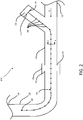
- the water system 100 comprises a first tube 110, a second tube 120, an electrical interface 130, and an internal heating trace assembly 140.
- the first tube 110 may comprise a wye shape, a tee shape, or the like.
- the first tube 110 may comprise a water inlet 112, a water outlet 114, and a heating trace inlet 116.
- the second tube 120 may comprise a water inlet 122 and a water outlet 124.
- the water inlet 122 of the second tube 120 may be coupled to the water outlet 114 of the first tube 110 by any method known in the art.
- water inlet 122 of the second tube 120 may be coupled to the water outlet 114 of the first tube 110 by a coupling 118, such as a threaded fitting, two-ferrule fitting, a single ferrule fitting, a ferrule-less push-fit connector, a collar fitting, or the like.
- the coupling 118 may comprise bonding or soldering first tube 110 to second tube 120.
- the water system 100 may flow in a first direction B from water inlet 112 from first tube 110 through water outlet 124 of second tube 120.
- electrical interface 130 is disposed at the heating trace inlet 116 of the first tube 110.
- the electrical interface 130 may be any electrical interface 130 known in the art, such as an electrical connector or the like.
- the electrical interface 130 may be in electrical communication with a controller and/or a monitoring system.
- the electrical interface 130 is coupled to the internal heating trace assembly 140.
- the internal heating trace assembly 140 is in electrical communication with the electrical interface 130.
- a first end 142 internal heating trace assembly 140 is fixed at the electrical interface 130 and the second end 144 is free within the water system 100.
- second end 144 may be free in second tube 120 or an upstream tube in water system 100.
- the internal heating trace assembly 140 may be configured to control a temperature of water disposed in water system 100 during operation.
- bus wires disposed in the internal heating trace assembly 140 may conduct current from the electrical interface 130 through the length of the internal heating trace assembly 140 during operation.
- internal heating trace assembly 140 comprises a plurality of ceramic PTC elements 146 disposed in parallel along a length of the internal heating trace assembly 140.
- each ceramic PTC element in the plurality of ceramic PTC elements 146 may act as a resistor.
- Each ceramic PTC element in the plurality of ceramic PTC elements 146 is a discrete ceramic PTC element in relation to an adjacent ceramic PTC element.
- the internal heating trace assembly 140 may be configured to control a temperature of the internal heating trace assembly 140, and in turn the water in water system 100, continuously along the length of the internal heating trace assembly 140.
- the plurality of ceramic PTC elements 146 are uniformly spaced about the internal heating trace assembly 140. In various embodiments, the spacing between adjacent ceramic PTC elements in the plurality of ceramic PTC elements varies along the length of the internal heating trace assembly 140. As such, an internal heating trace assembly 140 may be configured based on a specific design application. For example, one area may need greater temperature than another area of the internal heating trace assembly 140, so more PTC elements may be placed in the area that would benefit from greater temperature applied compared to another area of the internal heating trace assembly 140. Additionally, ceramic PTC elements have greater thermal stability compared to typical PTC polymers; however, ceramic PTC elements may be more brittle than typical PTC polymers. By orienting the ceramic PTC elements in parallel, electrically and physically, the ceramic PTC elements may be more structurally sound compared to a ceramic PTC element extending along the entire length of the internal heating trace assembly 140.
- water system 100 is disclosed with respect to an aircraft 10, any water system with temperature control is within the scope of this disclosure.
- Internal heating trace assembly 140 comprises a ceramic PTC element 210, a first bus bar 220, a second bus bar 230, and an insulator 240.
- the plurality of ceramic PTC elements 146 from FIG. 2 may include the ceramic PTC element 210.
- the ceramic PTC element 210 may be disposed between, and coupled to, the first bus bar 220 and the second bus bar 230.
- the ceramic PTC element is in electrical communication with the first bus bar 220 and the second bus bar 230.
- the first bus bar 220 and the second bus bar 230 may be any conductive element known in the art, such as a wire or the like.
- the first bus bar 220 and the second bus bar 230 may be electrically coupled to the electrical interface 130 from FIG. 2 .
- the first bus bar 220 and the second bus bar 230 may be configured to carry an electrical current and the ceramic PTC element 210 may be configured to act as a resistor in internal heating trace assembly 140.
- insulator 240 is disposed around the first bus bar 220, the second bus bar 230, and the ceramic PTC element 210.
- the insulator 240 may be any electrical insulator known in the art (e.g., polyethylene, cross linked polyethylene-XLPE, polyvinyl chloride PVC, Polytetrafluorethylene (PTFE), silicone, polyolefin, fluoropolymer, etc.).
- the insulator 240 may be configured to insulate the electricity generated from the first bus bar 220, the second bus bar 230, and the ceramic PTC element 210 from the water disposed in water system 100 from FIG. 2 .
- each ceramic PTC element 210 in the plurality of ceramic PTC elements of an internal heating trace assembly may be electrically coupled to the first bus bar 220 and the second bus bar 230 by any method known in the art (e.g., soldering). After the plurality of ceramic PTC elements are coupled to the first bus bar 220 and the second bus bar 230, the first bus bar 220, second bus bar 230, and the plurality of ceramic PTC elements are disposed in an insulator 240.
- the insulator 240 is a heat-shrink tubing 242.
- the first bus bar 220, the second bus bar 230, and the plurality of ceramic PTC elements may easily be disposed in heat-shrink tubing 242 in its un-shrunk state ( FIG. 3B ).
- heat is applied to the heat-shrink tubing 242 by any method known in the art, such as via an oven, a hot air gun, a source of hot gas, or the like.
- heat-shrink tubing 242 may shrink and contact the first bus bar 220, the second bus bar 230, and the ceramic PTC element 210 (as shown in FIG. 3A ), resulting in an internal heating trace assembly 140.
- the heat-shrink tubing 242 may be any thermoplastic material known in the art, such as elastomeric, fluorinated ethylene propylene (FEP), polyolefin, or the like.
- the heat-shrink tubing 242 may include an internal layer of hot-melt adhesive to enhance the thermal bond between heat-shrink tubing 242 and the PTC elements 210.
- the internal heating trace assembly comprises a first bus bar 220, a second bus bar 230, and a plurality of ceramic PTC elements 310 disposed in parallel.
- Each ceramic PTC element in the plurality of ceramic PTC elements 310 may comprise a first side and a second side.
- first ceramic PTC element 320 in the plurality of ceramic PTC elements 310 may comprise a first side 322 and a second side 324.
- the first side 322 may be coupled to first bus bar 220 by any method known in the art (e.g., soldering).
- each ceramic PTC element in the plurality of ceramic PTC elements 310 may comprise a ceramic PTC strip extending from first bus bar 220 to second bus bar 230.
- the first ceramic PTC element 320 may comprise a ceramic PTC strip extending from first bus bar 220 to second bus bar 230.
- the internal heating trace assembly 400 comprises a first bus bar 220, a second bus bar 230, and a plurality of ceramic PTC elements 410 disposed in parallel.
- Each ceramic PTC element in the plurality of ceramic PTC elements 310 may comprise a ceramic PTC bead.
- first ceramic PTC element 420 in the plurality of ceramic PTC elements 410 may comprise a ceramic PTC bead 430.
- the ceramic PTC bead 430 may be disposed between the first bus bar 220 and the second bus bar 230.
- the ceramic PTC bead 430 may be coupled to the first bus bar 220 via a first conductive leg 422 extending from ceramic PTC bead 430 to the first bus bar 220.
- ceramic PTC bead 430 may be coupled to the second bus bar via a second conductive leg 424 extending from ceramic PTC bead 430 to the second bus bar 230.
- first conductive leg 422 has a first end 421 and a second end 423.
- first conductive leg 422 may be coupled to first bus bar 220 by any method known in the art (e.g., soldering) and the second end 423 of first conductive leg 422 may be coupled to ceramic PTC bead 430 by any method known in the art (e.g., soldering).
- the second conductive leg 424 may be coupled to ceramic PTC bead 430 and second bus bar 230 in the same manner as first conductive leg 422.
- the first conductive leg 422 and the second conductive leg 424 may be any conductive material known in the art (e.g., copper, silver, or the like).
- the method may comprise coupling a ceramic PTC element to a first bus bar (step 502).
- the ceramic PTC element may be a ceramic PTC strip (as illustrated in FIG 4A ), a ceramic PTC bead (as illustrated in FIG 4B ), or the like.
- the first bus bar may be any conductive element known in the art, such as a copper wire or the like.
- the PTC element may be coupled to the first bus bar by soldering, or any other method known in the art.
- the method may further comprise coupling the ceramic PTC element to a second bus bar (step 504).
- the ceramic PTC element may be coupled to the second bus bar in the same manner as the ceramic PTC element is coupled to the first bus bar.
- the second bus bar may be of equal length as the first bus bar.
- the method may further comprise repeating steps 502 and 504 until a plurality of ceramic PTC elements are disposed in parallel between the first bus bar and the second bus bar.
- the number of ceramic PTC elements for a given application may be a design choice based on the heating requirements of a given system.
- the method may further comprise disposing the plurality of ceramic PTC elements, the first bus bar, and the second bus bar in a heat-shrink tubing (step 506).
- the heat-shrink tubing may be any heat-shrink tubing known in the art, such as heat-shrink tubing 242 (from FIG. 3B ).
- the method may further comprise applying heat to the heat-shrink tubing (step 508). By applying heat to the heat-shrink tubing, the heat-shrink tubing may shrink and wrap tightly around the first bus bar, the second bus bar, and the plurality of ceramic PTC elements.
- the method may further comprise sealing a first end of heat-shrink tubing (step 510).
- the first end may be sealed by any method known in the art, such as a heat-shrink end cap or the like.
- the second end may have the first bus bar and the second bus bar exposed and/or extending out of the second end of the heat-shrink tubing to allow the first bus bar and the second bus bar to be coupled to an electrical component.
- the second end of the heat shrink tubing may be sealed in a manner similar to the first end of the heat-shrink tubing, and the wires may be exposed just prior to use (i.e., just prior to electrically coupling the wires to an electrical component.
- references to "various embodiments”, “one embodiment”, “an embodiment”, “an example embodiment”, etc. indicate that the embodiment described may include a particular feature, structure, or characteristic, but every embodiment may not necessarily include the particular feature, structure, or characteristic. Moreover, such phrases are not necessarily referring to the same embodiment. Further, when a particular feature, structure, or characteristic is described in connection with an embodiment, it is submitted that it is within the knowledge of one skilled in the art to affect such feature, structure, or characteristic in connection with other embodiments whether or not explicitly described. After reading the description, it will be apparent to one skilled in the relevant art(s) how to implement the disclosure in alternative embodiments.
Landscapes
- Engineering & Computer Science (AREA)
- General Engineering & Computer Science (AREA)
- Chemical & Material Sciences (AREA)
- Ceramic Engineering (AREA)
- Aviation & Aerospace Engineering (AREA)
- Mechanical Engineering (AREA)
- Resistance Heating (AREA)
Abstract
Description
- The present disclosure relates to a heating trace system, and more particularly, to internal heating trace assembly use in a heating trace system.
- Internal heating traces may be utilized in tube assemblies to regulate temperature of a fluid disposed in the tube assemblies. Internal heating traces may rely on a controller to prevent overheating. Typical internal heating traces may have relatively loose temperature control.
- An internal heating trace assembly is disclosed herein. The internal heating trace assembly may comprise: an insulator configured to insulate electricity; a first bus bar disposed within the insulator; a second bus bar disposed within the insulator; and a plurality of ceramic positive temperature coefficient (PTC) elements disposed in parallel between the first bus bar and the second bus bar.
- In various embodiments, each ceramic PTC element in the plurality of ceramic PTC elements is a ceramic PTC strip. The ceramic PTC strip may extend from the first bus bar to the second bus bar. The ceramic PTC strip may comprise a first side and a second side, wherein the first side soldered to the first bus bar, and wherein the second side is soldered to the second bus bar. Each ceramic PTC element in the plurality of ceramic PTC elements may be a ceramic PTC bead. The internal heating trace assembly may further comprise a first conductive leg and a second conductive leg, the first conductive leg disposed between the first bus bar and the ceramic PTC bead, the second conductive leg disposed between the second bus bar and the ceramic PTC bead. The first conductive leg may be soldered to the first bus bar and the ceramic PTC bead. The second conductive leg may be soldered to the second bus bar and the ceramic PTC bead. The insulator may comprise heat-shrink tubing.
- A water system for use on an aircraft is disclosed herein. The water system may comprise: a tube including a first inlet, a second inlet, and an outlet, the second inlet disposed between the first inlet and the outlet; an electrical interface disposed at the second inlet; an internal heating trace assembly disposed in the tube, a first end of the internal heating trace assembly coupled to the electrical interface, the internal heating trace assembly comprising: an insulator configured to insulate electricity; a first bus bar disposed within the insulator, the first bus bar in electrical communication with the electrical interface; a second bus bar disposed within the insulator, the second bus bar in electrical communication with the electrical interface; and a plurality of ceramic positive temperature coefficient (PTC) elements disposed in parallel between the first bus bar and the second bus bar.
- In various embodiments, the internal heating trace assembly may comprise a second end, and wherein the second end is configured to float freely during operation of the water system. The water may be configured to flow from the first inlet to the outlet. Each ceramic PTC element in the plurality of ceramic PTC elements may be a ceramic PTC strip. The ceramic PTC strip may extend from the first bus bar to the second bus bar. The ceramic PTC strip may comprise a first side and a second side. The first side may be soldered to the first bus bar. The second side may be soldered to the second bus bar. Each ceramic PTC element in the plurality of ceramic PTC elements may be a ceramic PTC bead. The internal heating trace assembly may further comprise a first conductive leg and a second conductive leg, the first conductive leg disposed between the first bus bar and the ceramic PTC bead, the second conductive leg disposed between the second bus bar and the ceramic PTC bead. The first conductive leg may be soldered to the first bus bar and the ceramic PTC bead, wherein the second conductive leg is soldered to the second bus bar and the ceramic PTC bead. The insulator may comprise heat-shrink tubing.
- A method of manufacturing an internal heating trace assembly is disclosed herein. The method may comprise: coupling a first ceramic positive temperature coefficient (PTC) element to a first bus bar; coupling the first ceramic PTC element to a second bus bar; coupling a second ceramic PTC element to the first bus bar; coupling the second ceramic PTC element to the second bus bar; disposing the first ceramic PTC element, the second ceramic PTC element, the first bus bar, and the second bus bar in a heat-shrink tubing; and applying heat to the heat-shrink tubing. In various embodiments, the method may further comprise sealing a first end of the heat-shrink tubing.
- The foregoing features and elements may be combined in various combinations without exclusivity, unless expressly indicated otherwise. These features and elements as well as the operation thereof will become more apparent in light of the following description and the accompanying drawings. It should be understood, however, the following description and drawings are intended to be exemplary in nature and nonlimiting.
- The subject matter of the present disclosure is particularly pointed out and distinctly claimed in the concluding portion of the specification. A more complete understanding of the present disclosure, however, may best be obtained by referring to the detailed description and claims when considered in connection with the following illustrative figures. In the following figures, like reference numbers refer to similar elements and steps throughout the figures.
-
FIG. 1 illustrates a plain view showing an aircraft, in accordance with various embodiments; -
FIG. 2 illustrates a potable water system of an aircraft, in accordance with various embodiments; -
FIG. 3A illustrates a cross-sectional view of an internal heating trace assembly, in accordance with various embodiments; -
FIG. 3B illustrates a cross-sectional view of an internal heating trace assembly during manufacturing, in accordance with various embodiments; -
FIG. 4A illustrates a portion of an internal heating trace assembly, in accordance with various embodiments; -
FIG. 4B illustrates a portion of an internal heating trace assembly, in accordance with various embodiments; and -
FIG. 5 illustrates a method of manufacturing an internal heating trace assembly, in accordance with various embodiments. - Elements and steps in the figures are illustrated for simplicity and clarity and have not necessarily been rendered according to any particular sequence. For example, steps that may be performed concurrently or in different order are illustrated in the figures to help to improve understanding of embodiments of the present disclosure.
- The detailed description of exemplary embodiments herein makes reference to the accompanying drawings, which show exemplary embodiments by way of illustration. While these exemplary embodiments are described in sufficient detail to enable those skilled in the art to practice the disclosures, it should be understood that other embodiments may be realized and that logical changes and adaptations in design and construction may be made in accordance with this disclosure and the teachings herein. Thus, the detailed description herein is presented for purposes of illustration only and not of limitation.
- The scope of the disclosure is defined by the appended claims and their legal equivalents rather than by merely the examples described. For example, the steps recited in any of the method or process descriptions may be executed in any order and are not necessarily limited to the order presented. Furthermore, any reference to singular includes plural embodiments, and any reference to more than one component or step may include a singular embodiment or step. Also, any reference to tacked, attached, fixed, coupled, connected or the like may include permanent, removable, temporary, partial, full and/or any other possible attachment option. Additionally, any reference to without contact (or similar phrases) may also include reduced contact or minimal contact.
- Disclosed herein is an internal heating trace assembly. The internal heating trace assembly comprises, in various embodiments, a first bus bar, a second bus bar, and a plurality of ceramic Positive Temperature Coefficient (PTC) elements. The ceramic PTC elements may be disposed in parallel between the bus bars. The internal heating trace assembly may further comprise an electrical insulator. The first bus bar, second bus bar, and plurality of ceramic PTC elements may be disposed within the insulator. The internal heating trace assembly, in various embodiments, may be configured to provide temperature control continuously along the length of the internal trace heating assembly. The internal heating trace assembly may generate power savings in a heating trace system.
- With reference to
FIG. 1 , anaircraft 10 is provided with afuselage 20, aleft side wing 12 and aright side wing 14. Theleft side wing 12 andright side wing 14 are designed to provide lift to the aircraft and enable it to fly. Thefuselage 20 may house passengers, as well as various components configured to operateaircraft 10. In various embodiments, thefuselage 20 may comprise awater system 100.Water system 100 may be a potable water system, a gray water system, or the like.Water system 100 may be disposed in an area offuselage 20 that is susceptible to outside temperature control. As such, at high altitudes,water system 100 may be exposed to temperatures below freezing.Water system 100 may be temperature controlled by an internal heating trace assembly. - Referring now to
FIG. 2 , a schematic view of a portion of awater system 100 for use on anaircraft 10, in accordance with various embodiments, is illustrated. Thewater system 100 comprises afirst tube 110, asecond tube 120, anelectrical interface 130, and an internalheating trace assembly 140. Thefirst tube 110 may comprise a wye shape, a tee shape, or the like. Thefirst tube 110 may comprise awater inlet 112, awater outlet 114, and aheating trace inlet 116. Thesecond tube 120 may comprise awater inlet 122 and awater outlet 124. Thewater inlet 122 of thesecond tube 120 may be coupled to thewater outlet 114 of thefirst tube 110 by any method known in the art. For example,water inlet 122 of thesecond tube 120 may be coupled to thewater outlet 114 of thefirst tube 110 by acoupling 118, such as a threaded fitting, two-ferrule fitting, a single ferrule fitting, a ferrule-less push-fit connector, a collar fitting, or the like. In various embodiments, thecoupling 118 may comprise bonding or solderingfirst tube 110 tosecond tube 120. Thewater system 100 may flow in a first direction B fromwater inlet 112 fromfirst tube 110 throughwater outlet 124 ofsecond tube 120. - In various embodiments,
electrical interface 130 is disposed at theheating trace inlet 116 of thefirst tube 110. Theelectrical interface 130 may be anyelectrical interface 130 known in the art, such as an electrical connector or the like. Theelectrical interface 130 may be in electrical communication with a controller and/or a monitoring system. Theelectrical interface 130 is coupled to the internalheating trace assembly 140. The internalheating trace assembly 140 is in electrical communication with theelectrical interface 130. Afirst end 142 internalheating trace assembly 140 is fixed at theelectrical interface 130 and thesecond end 144 is free within thewater system 100. For example,second end 144 may be free insecond tube 120 or an upstream tube inwater system 100. The internalheating trace assembly 140 may be configured to control a temperature of water disposed inwater system 100 during operation. In various embodiments, bus wires disposed in the internalheating trace assembly 140 may conduct current from theelectrical interface 130 through the length of the internalheating trace assembly 140 during operation. - In various embodiments, internal
heating trace assembly 140 comprises a plurality ofceramic PTC elements 146 disposed in parallel along a length of the internalheating trace assembly 140. In various embodiments, each ceramic PTC element in the plurality ofceramic PTC elements 146 may act as a resistor. Each ceramic PTC element in the plurality ofceramic PTC elements 146 is a discrete ceramic PTC element in relation to an adjacent ceramic PTC element. As such, the internalheating trace assembly 140 may be configured to control a temperature of the internalheating trace assembly 140, and in turn the water inwater system 100, continuously along the length of the internalheating trace assembly 140. - In various embodiments, the plurality of
ceramic PTC elements 146 are uniformly spaced about the internalheating trace assembly 140. In various embodiments, the spacing between adjacent ceramic PTC elements in the plurality of ceramic PTC elements varies along the length of the internalheating trace assembly 140. As such, an internalheating trace assembly 140 may be configured based on a specific design application. For example, one area may need greater temperature than another area of the internalheating trace assembly 140, so more PTC elements may be placed in the area that would benefit from greater temperature applied compared to another area of the internalheating trace assembly 140. Additionally, ceramic PTC elements have greater thermal stability compared to typical PTC polymers; however, ceramic PTC elements may be more brittle than typical PTC polymers. By orienting the ceramic PTC elements in parallel, electrically and physically, the ceramic PTC elements may be more structurally sound compared to a ceramic PTC element extending along the entire length of the internalheating trace assembly 140. - Although
water system 100 is disclosed with respect to anaircraft 10, any water system with temperature control is within the scope of this disclosure. - Referring now to
FIG. 3A , a cross-sectional view of internalheating trace assembly 140 along section A-A fromFIG. 2 , in accordance with various embodiments, is illustrated. Internalheating trace assembly 140 comprises aceramic PTC element 210, afirst bus bar 220, asecond bus bar 230, and aninsulator 240. In various embodiments, the plurality ofceramic PTC elements 146 fromFIG. 2 may include theceramic PTC element 210. Theceramic PTC element 210 may be disposed between, and coupled to, thefirst bus bar 220 and thesecond bus bar 230. In various embodiment, the ceramic PTC element is in electrical communication with thefirst bus bar 220 and thesecond bus bar 230. Thefirst bus bar 220 and thesecond bus bar 230 may be any conductive element known in the art, such as a wire or the like. Thefirst bus bar 220 and thesecond bus bar 230 may be electrically coupled to theelectrical interface 130 fromFIG. 2 . Thefirst bus bar 220 and thesecond bus bar 230 may be configured to carry an electrical current and theceramic PTC element 210 may be configured to act as a resistor in internalheating trace assembly 140. - In various embodiments,
insulator 240 is disposed around thefirst bus bar 220, thesecond bus bar 230, and theceramic PTC element 210. Theinsulator 240 may be any electrical insulator known in the art (e.g., polyethylene, cross linked polyethylene-XLPE, polyvinyl chloride PVC, Polytetrafluorethylene (PTFE), silicone, polyolefin, fluoropolymer, etc.). Theinsulator 240 may be configured to insulate the electricity generated from thefirst bus bar 220, thesecond bus bar 230, and theceramic PTC element 210 from the water disposed inwater system 100 fromFIG. 2 . - Referring now to
FIG. 3B , a cross-section of internalheating trace assembly 140 during manufacturing, in accordance with various embodiments, is illustrated. In various embodiments, eachceramic PTC element 210 in the plurality of ceramic PTC elements of an internal heating trace assembly may be electrically coupled to thefirst bus bar 220 and thesecond bus bar 230 by any method known in the art (e.g., soldering). After the plurality of ceramic PTC elements are coupled to thefirst bus bar 220 and thesecond bus bar 230, thefirst bus bar 220,second bus bar 230, and the plurality of ceramic PTC elements are disposed in aninsulator 240. - In various embodiments, the
insulator 240 is a heat-shrink tubing 242. As such, thefirst bus bar 220, thesecond bus bar 230, and the plurality of ceramic PTC elements may easily be disposed in heat-shrink tubing 242 in its un-shrunk state (FIG. 3B ). After thefirst bus bar 220, thesecond bus bar 230, and the plurality of ceramic PTC elements are disposed in the heat-shrink tubing 242, heat is applied to the heat-shrink tubing 242 by any method known in the art, such as via an oven, a hot air gun, a source of hot gas, or the like. As a result, heat-shrink tubing 242 may shrink and contact thefirst bus bar 220, thesecond bus bar 230, and the ceramic PTC element 210 (as shown inFIG. 3A ), resulting in an internalheating trace assembly 140. The heat-shrink tubing 242 may be any thermoplastic material known in the art, such as elastomeric, fluorinated ethylene propylene (FEP), polyolefin, or the like. The heat-shrink tubing 242 may include an internal layer of hot-melt adhesive to enhance the thermal bond between heat-shrink tubing 242 and thePTC elements 210. - Referring now to
FIG. 4A , a portion of an internal heating trace assembly (140, 300), in accordance with various embodiments, is illustrated. The internal heating trace assembly comprises afirst bus bar 220, asecond bus bar 230, and a plurality ofceramic PTC elements 310 disposed in parallel. Each ceramic PTC element in the plurality ofceramic PTC elements 310 may comprise a first side and a second side. For example, firstceramic PTC element 320 in the plurality ofceramic PTC elements 310 may comprise afirst side 322 and asecond side 324. Thefirst side 322 may be coupled tofirst bus bar 220 by any method known in the art (e.g., soldering). Similarly,second side 324 may be coupled tosecond bus bar 230 by any method known in the art (e.g., soldering). As such, each ceramic PTC element in the plurality ofceramic PTC elements 310 may comprise a ceramic PTC strip extending fromfirst bus bar 220 tosecond bus bar 230. For example, the firstceramic PTC element 320 may comprise a ceramic PTC strip extending fromfirst bus bar 220 tosecond bus bar 230. - Referring now to
FIG. 4B , a portion of an internal heating trace assembly (140, 400), in accordance with various embodiments, is illustrated. The internalheating trace assembly 400 comprises afirst bus bar 220, asecond bus bar 230, and a plurality ofceramic PTC elements 410 disposed in parallel. Each ceramic PTC element in the plurality ofceramic PTC elements 310 may comprise a ceramic PTC bead. For example, firstceramic PTC element 420 in the plurality ofceramic PTC elements 410 may comprise aceramic PTC bead 430. Theceramic PTC bead 430 may be disposed between thefirst bus bar 220 and thesecond bus bar 230. - The
ceramic PTC bead 430 may be coupled to thefirst bus bar 220 via a firstconductive leg 422 extending fromceramic PTC bead 430 to thefirst bus bar 220. Similarly,ceramic PTC bead 430 may be coupled to the second bus bar via a secondconductive leg 424 extending fromceramic PTC bead 430 to thesecond bus bar 230. In various embodiments, firstconductive leg 422 has a first end 421 and a second end 423. The first end 421 of firstconductive leg 422 may be coupled tofirst bus bar 220 by any method known in the art (e.g., soldering) and the second end 423 of firstconductive leg 422 may be coupled toceramic PTC bead 430 by any method known in the art (e.g., soldering). The secondconductive leg 424 may be coupled toceramic PTC bead 430 andsecond bus bar 230 in the same manner as firstconductive leg 422. The firstconductive leg 422 and the secondconductive leg 424 may be any conductive material known in the art (e.g., copper, silver, or the like). - Referring now to
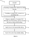
FIG. 5 , amethod 500 for manufacturing an internal heating trace assembly, in accordance with various embodiments, is illustrated. The method may comprise coupling a ceramic PTC element to a first bus bar (step 502). The ceramic PTC element may be a ceramic PTC strip (as illustrated inFIG 4A ), a ceramic PTC bead (as illustrated inFIG 4B ), or the like. The first bus bar may be any conductive element known in the art, such as a copper wire or the like. The PTC element may be coupled to the first bus bar by soldering, or any other method known in the art. The method may further comprise coupling the ceramic PTC element to a second bus bar (step 504). The ceramic PTC element may be coupled to the second bus bar in the same manner as the ceramic PTC element is coupled to the first bus bar. The second bus bar may be of equal length as the first bus bar. - The method may further comprise repeating
steps FIG. 3B ). The method may further comprise applying heat to the heat-shrink tubing (step 508). By applying heat to the heat-shrink tubing, the heat-shrink tubing may shrink and wrap tightly around the first bus bar, the second bus bar, and the plurality of ceramic PTC elements. - The method may further comprise sealing a first end of heat-shrink tubing (step 510). The first end may be sealed by any method known in the art, such as a heat-shrink end cap or the like. The second end may have the first bus bar and the second bus bar exposed and/or extending out of the second end of the heat-shrink tubing to allow the first bus bar and the second bus bar to be coupled to an electrical component. In various embodiments, the second end of the heat shrink tubing may be sealed in a manner similar to the first end of the heat-shrink tubing, and the wires may be exposed just prior to use (i.e., just prior to electrically coupling the wires to an electrical component.
- Benefits, other advantages, and solutions to problems have been described herein with regard to specific embodiments. Furthermore, the connecting lines shown in the various figures contained herein are intended to represent exemplary functional relationships and/or physical couplings between the various elements. It should be noted that many alternative or additional functional relationships or physical connections may be present in a practical system. However, the benefits, advantages, solutions to problems, and any elements that may cause any benefit, advantage, or solution to occur or become more pronounced are not to be construed as critical, required, or essential features or elements of the disclosures. The scope of the disclosures is accordingly to be limited by nothing other than the appended claims and their legal equivalents, in which reference to an element in the singular is not intended to mean "one and only one" unless explicitly so stated, but rather "one or more." Moreover, where a phrase similar to "at least one of A, B, or C" is used in the claims, it is intended that the phrase be interpreted to mean that A alone may be present in an embodiment, B alone may be present in an embodiment, C alone may be present in an embodiment, or that any combination of the elements A, B and C may be present in a single embodiment; for example, A and B, A and C, B and C, or A and B and C.
- Systems, methods and apparatus are provided herein. In the detailed description herein, references to "various embodiments", "one embodiment", "an embodiment", "an example embodiment", etc., indicate that the embodiment described may include a particular feature, structure, or characteristic, but every embodiment may not necessarily include the particular feature, structure, or characteristic. Moreover, such phrases are not necessarily referring to the same embodiment. Further, when a particular feature, structure, or characteristic is described in connection with an embodiment, it is submitted that it is within the knowledge of one skilled in the art to affect such feature, structure, or characteristic in connection with other embodiments whether or not explicitly described. After reading the description, it will be apparent to one skilled in the relevant art(s) how to implement the disclosure in alternative embodiments.
- Furthermore, no element, component, or method step in the present disclosure is intended to be dedicated to the public regardless of whether the element, component, or method step is explicitly recited in the claims. As used herein, the terms "comprises", "comprising", or any other variation thereof, are intended to cover a non-exclusive inclusion, such that a process, method, article, or apparatus that comprises a list of elements does not include only those elements but may include other elements not expressly listed or inherent to such process, method, article, or apparatus.
Claims (15)
- An internal heating trace assembly (140), comprising:an insulator (240) configured to insulate electricity;a first bus bar (220) disposed within the insulator;a second bus bar (230) disposed within the insulator; anda plurality of ceramic positive temperature coefficient, PTC, elements (210) disposed in parallel between the first bus bar and the second bus bar.
- The internal heating trace assembly of claim 1, wherein each ceramic PTC element (210) in the plurality of ceramic PTC elements is a ceramic PTC strip.
- The internal heating trace assembly of claim 2, wherein the ceramic PTC strip extends from the first bus bar to the second bus bar.
- The internal heating trace assembly of claim 3, wherein the ceramic PTC strip comprises a first side and a second side, wherein the first side soldered to the first bus bar, and wherein the second side is soldered to the second bus bar.
- The internal heating trace assembly of claim 1, wherein each ceramic PTC element (210) in the plurality of ceramic PTC elements is a ceramic PTC bead (430).
- The internal heating trace assembly of claim 5, further comprising a first conductive leg (422) and a second conductive leg (424), the first conductive leg disposed between the first bus bar and the ceramic PTC bead, the second conductive leg disposed between the second bus bar and the ceramic PTC bead, and preferably wherein the first conductive leg is soldered to the first bus bar and the ceramic PTC bead, wherein the second conductive leg is soldered to the second bus bar and the ceramic PTC bead.
- The internal heating trace assembly of any preceding claim, wherein the insulator comprises heat-shrink tubing (242).
- A water system for use on an aircraft, the water system comprising:a tube (110) including a first inlet (112), a second inlet (114), and an outlet (116), the second inlet disposed between the first inlet and the outlet;an electrical interface (130) disposed at the second inlet;an internal heating trace assembly (140) disposed in the tube, a first end of the internal heating trace assembly coupled to the electrical interface, the internal heating trace assembly comprising:an insulator (240) configured to insulate electricity;a first bus bar (220) disposed within the insulator, the first bus bar in electrical communication with the electrical interface;a second bus bar (230) disposed within the insulator, the second bus bar in electrical communication with the electrical interface; anda plurality of ceramic positive temperature coefficient, PTC, elements (210) disposed in parallel between the first bus bar and the second bus bar.
- The water system of claim 8, wherein the internal heating trace assembly (140) comprises a second end, and wherein the second end is configured to float freely during operation of the water system.
- The water system of claim 8 or 9, wherein water is configured to flow from the first inlet to the outlet.
- The water system of any of claims 8-10, wherein each ceramic PTC element (210) in the plurality of ceramic PTC elements is a ceramic PTC strip, and preferably wherein the ceramic PTC strip extends from the first bus bar to the second bus bar, and more preferably wherein the ceramic PTC strip comprises a first side and a second side, wherein the first side is soldered to the first bus bar, and wherein the second side is soldered to the second bus bar.
- The water system of any of claims 8-10, wherein each ceramic PTC element (210) in the plurality of ceramic PTC elements is a ceramic PTC bead, and preferably wherein the internal heating trace assembly further comprises a first conductive leg and a second conductive leg, the first conductive leg disposed between the first bus bar and the ceramic PTC bead, the second conductive leg disposed between the second bus bar and the ceramic PTC bead, and more preferably wherein the first conductive leg is soldered to the first bus bar and the ceramic PTC bead, wherein the second conductive leg is soldered to the second bus bar and the ceramic PTC bead.
- The water system of any of claims 8-12, wherein the insulator comprises heat-shrink tubing (242).
- A method of manufacturing an internal heating trace assembly, the method comprising:coupling a first ceramic positive temperature coefficient (PTC) element to a first bus bar;coupling the first ceramic PTC element to a second bus bar;coupling a second ceramic PTC element to the first bus bar;coupling the second ceramic PTC element to the second bus bar;disposing the first ceramic PTC element, the second ceramic PTC element, the first bus bar, and the second bus bar in a heat-shrink tubing; andapplying heat to the heat-shrink tubing.
- The method of claim 14, further comprising sealing a first end of the heat-shrink tubing.
Applications Claiming Priority (1)
| Application Number | Priority Date | Filing Date | Title |
|---|---|---|---|
| US16/713,442 US11903101B2 (en) | 2019-12-13 | 2019-12-13 | Internal heating trace assembly |
Publications (1)
| Publication Number | Publication Date |
|---|---|
| EP3836748A1 true EP3836748A1 (en) | 2021-06-16 |
Family
ID=73138571
Family Applications (1)
| Application Number | Title | Priority Date | Filing Date |
|---|---|---|---|
| EP20201810.7A Pending EP3836748A1 (en) | 2019-12-13 | 2020-10-14 | Internal heating trace assembly |
Country Status (2)
| Country | Link |
|---|---|
| US (1) | US11903101B2 (en) |
| EP (1) | EP3836748A1 (en) |
Citations (4)
| Publication number | Priority date | Publication date | Assignee | Title |
|---|---|---|---|---|
| US4700054A (en) * | 1983-11-17 | 1987-10-13 | Raychem Corporation | Electrical devices comprising fabrics |
| US4874925A (en) * | 1987-06-01 | 1989-10-17 | Dickenson Wilk A | Electrically heated hose assembly for conveying electrically conductive liquids |
| US5922233A (en) * | 1994-09-14 | 1999-07-13 | Sekisui Kasethin Kogyo Kabushiki Kaisha | Heater and manufacturing method thereof |
| US20130048128A1 (en) * | 2010-03-10 | 2013-02-28 | Airbus Operations Gmbh | Protection of water conduits against frost |
Family Cites Families (43)
| Publication number | Priority date | Publication date | Assignee | Title |
|---|---|---|---|---|
| US4642024A (en) | 1984-12-05 | 1987-02-10 | United Technologies Corporation | Coolable stator assembly for a rotary machine |
| US4849611A (en) * | 1985-12-16 | 1989-07-18 | Raychem Corporation | Self-regulating heater employing reactive components |
| US4791277A (en) * | 1987-02-09 | 1988-12-13 | Montierth Garry L | Heating and insulation arrangement for a network of installed pipes and method |
| US4899032A (en) | 1987-03-12 | 1990-02-06 | Siemens Aktiengesellschaft | Electric heating element utilizing ceramic PTC resistors for heating flooring media |
| US6111234A (en) * | 1991-05-07 | 2000-08-29 | Batliwalla; Neville S. | Electrical device |
| US5165847A (en) | 1991-05-20 | 1992-11-24 | General Electric Company | Tapered enlargement metering inlet channel for a shroud cooling assembly of gas turbine engines |
| US6229123B1 (en) * | 1998-09-25 | 2001-05-08 | Thermosoft International Corporation | Soft electrical textile heater and method of assembly |
| US6146091A (en) | 1998-03-03 | 2000-11-14 | Mitsubishi Heavy Industries, Ltd. | Gas turbine cooling structure |
| NL1008460C2 (en) | 1998-03-03 | 1999-09-06 | Acheson Colloiden B V | Conductive ink or paint. |
| US6350969B1 (en) | 2000-11-10 | 2002-02-26 | Jona Group, Ltd. | Self-regulating heater |
| US6868676B1 (en) | 2002-12-20 | 2005-03-22 | General Electric Company | Turbine containing system and an injector therefor |
| CN100386829C (en) | 2004-07-28 | 2008-05-07 | 王克政 | PTC thick film circuit controllable heating element |
| US7721292B2 (en) | 2004-12-16 | 2010-05-18 | International Business Machines Corporation | System for adjusting resource allocation to a logical partition based on rate of page swaps and utilization by changing a boot configuration file |
| SE529417C2 (en) * | 2005-12-22 | 2007-08-07 | Volvo Lastvagnar Ab | Wiring harness for a vehicle |
| GB0609729D0 (en) | 2006-05-17 | 2006-06-28 | Heat Trace Ltd | Material and heating cable |
| FR2907841B1 (en) | 2006-10-30 | 2011-04-15 | Snecma | TURBINE MACHINE RING SECTOR |
| US8256134B2 (en) | 2007-06-25 | 2012-09-04 | Pulse Holdings LLC | Drying apparatus and methods for ethanol production |
| GB0817082D0 (en) | 2008-09-18 | 2008-10-29 | Heat Trace Ltd | Heating cable |
| JP5283495B2 (en) * | 2008-12-11 | 2013-09-04 | 株式会社ジャムコ | Hot water supply system for aircraft |
| US8651802B2 (en) | 2010-03-17 | 2014-02-18 | United Technologies Corporation | Cover plate for turbine vane assembly |
| JP5557379B2 (en) | 2010-03-23 | 2014-07-23 | 矢崎総業株式会社 | Connection structure of crimp terminal to wire |
| WO2012011198A1 (en) * | 2010-07-21 | 2012-01-26 | Taguchi Koshiro | Highly efficient, hot water generating, car-mounted heater with internal liquid flow path |
| CN101945505A (en) | 2010-08-31 | 2011-01-12 | 上海吉龙经济发展有限公司 | Dual-waterway seal positive temperature coefficient (PTC) heater |
| US9181814B2 (en) | 2010-11-24 | 2015-11-10 | United Technology Corporation | Turbine engine compressor stator |
| US8826668B2 (en) | 2011-08-02 | 2014-09-09 | Siemens Energy, Inc. | Two stage serial impingement cooling for isogrid structures |
| US9049749B2 (en) | 2011-10-27 | 2015-06-02 | Shanghai Huazu Industry Co., Ltd. | Crimping fixed, remotely regulated electric heater |
| US9011079B2 (en) | 2012-01-09 | 2015-04-21 | General Electric Company | Turbine nozzle compartmentalized cooling system |
| US9845691B2 (en) | 2012-04-27 | 2017-12-19 | General Electric Company | Turbine nozzle outer band and airfoil cooling apparatus |
| CA2873679A1 (en) | 2012-05-16 | 2013-11-21 | Jka Kemi Ab | Deicing of a surface of structures in general such as wind turbine blades, aircraft wings using induction or radiation |
| DE102012106968B4 (en) | 2012-07-31 | 2023-11-23 | Dr. Ing. H.C. F. Porsche Aktiengesellschaft | Removable roof for a motor vehicle and motor vehicle |
| US20140193143A1 (en) * | 2013-01-04 | 2014-07-10 | Allied Precision Industries, Inc. | Heated hose assembly |
| US10100737B2 (en) | 2013-05-16 | 2018-10-16 | Siemens Energy, Inc. | Impingement cooling arrangement having a snap-in plate |
| NO337089B1 (en) * | 2014-03-13 | 2016-01-18 | Defa As | Fluid heating device |
| EP2933577B1 (en) * | 2014-04-14 | 2017-12-06 | Mahle Behr France Rouffach S.A.S | Electric heating device |
| DE102014110164B4 (en) | 2014-05-02 | 2022-11-03 | Borgwarner Ludwigsburg Gmbh | Process for manufacturing a heating rod |
| DE102014214690A1 (en) * | 2014-07-25 | 2016-01-28 | Contitech Techno-Chemie Gmbh | Heated hose |
| EP3186075A1 (en) | 2014-08-27 | 2017-07-05 | Basf Se | Rotor blade element with anti-icing surface for wind turbine rotor blades |
| US20160069570A1 (en) | 2014-09-05 | 2016-03-10 | Solar Turbines Incorporated | Method and apparatus for conditioning diffuser outlet flow |
| AU2015364502B2 (en) * | 2014-12-17 | 2017-12-14 | Rheem Manufacturing Company | Tankless electric water heater |
| US9994325B2 (en) | 2015-05-26 | 2018-06-12 | Goodrich Corporation | Polyether urethane deicer boots |
| EP3101998B1 (en) * | 2015-06-02 | 2020-12-16 | Eberspächer catem GmbH & Co. KG | Ptc heating element and electric heating device containing such a ptc heating element and method for manufacturing an electric heating device |
| EP3538611B1 (en) | 2016-11-09 | 2023-08-02 | Basf Se | Polyurethane comprising graphene nano structure |
| CN108164980A (en) | 2017-12-28 | 2018-06-15 | 山东诺威聚氨酯股份有限公司 | Carbon nano-tube modification TPU materials for 3D printing and preparation method thereof |
-
2019
- 2019-12-13 US US16/713,442 patent/US11903101B2/en active Active
-
2020
- 2020-10-14 EP EP20201810.7A patent/EP3836748A1/en active Pending
Patent Citations (4)
| Publication number | Priority date | Publication date | Assignee | Title |
|---|---|---|---|---|
| US4700054A (en) * | 1983-11-17 | 1987-10-13 | Raychem Corporation | Electrical devices comprising fabrics |
| US4874925A (en) * | 1987-06-01 | 1989-10-17 | Dickenson Wilk A | Electrically heated hose assembly for conveying electrically conductive liquids |
| US5922233A (en) * | 1994-09-14 | 1999-07-13 | Sekisui Kasethin Kogyo Kabushiki Kaisha | Heater and manufacturing method thereof |
| US20130048128A1 (en) * | 2010-03-10 | 2013-02-28 | Airbus Operations Gmbh | Protection of water conduits against frost |
Also Published As
| Publication number | Publication date |
|---|---|
| US20210185771A1 (en) | 2021-06-17 |
| US11903101B2 (en) | 2024-02-13 |
Similar Documents
| Publication | Publication Date | Title |
|---|---|---|
| CN103608170B (en) | multilayer electric heating medium pipeline | |
| US9644776B2 (en) | Prefabricated electrically heatable media line and method for producing a media line of this kind | |
| US20110274418A1 (en) | Fluid conduit with ptc fabric heating | |
| CN105051440B (en) | Prefabricated heatable media line, use of such a media line and method for producing same | |
| CN111050437B (en) | Three-dimensional printing type heating positive temperature coefficient tube | |
| US7626146B2 (en) | Modular heater systems | |
| US6005232A (en) | Heating cable | |
| EP0312204A2 (en) | Conductive polymeric conduit heater | |
| JP3720365B2 (en) | Heater and manufacturing method thereof | |
| JPWO1996008613A1 (en) | Heater and manufacturing method thereof | |
| US4756781A (en) | Method of connecting non-contaminating fluid heating element to a power source | |
| US11903101B2 (en) | Internal heating trace assembly | |
| CA3101116A1 (en) | Conductive ink with enhanced mechanical fatigue resistance | |
| CN219104209U (en) | Temperature sensing element | |
| US8274019B2 (en) | High temperature connector and method for manufacturing | |
| US9395102B2 (en) | Self regulating inline heater | |
| CN103574212A (en) | Pipe assembly for the flow of a fluid and of a current and method for assembling such a pipe assembly | |
| KR20160118849A (en) | Resistance adjustable carbon fiber heating element | |
| EP3574709B1 (en) | Devices for heating small-diameter tubing and methods of making and using | |
| JP2003262425A (en) | Heating / cooling strip and heating / cooling device | |
| EP2966334B1 (en) | Heated flow line for a fluid-feeding system in a motor vehicle | |
| EP4124174A1 (en) | Thin-lightweight-smart heater for freeze protection of aircraft waste fluid systems | |
| CN111968781A (en) | Motor wire and preparation method thereof | |
| CN215172926U (en) | Electric heating heat-preserving anti-freezing water hose | |
| CN109378617A (en) | A kind of novel solder ring connector |
Legal Events
| Date | Code | Title | Description |
|---|---|---|---|
| PUAI | Public reference made under article 153(3) epc to a published international application that has entered the european phase |
Free format text: ORIGINAL CODE: 0009012 |
|
| STAA | Information on the status of an ep patent application or granted ep patent |
Free format text: STATUS: THE APPLICATION HAS BEEN PUBLISHED |
|
| AK | Designated contracting states |
Kind code of ref document: A1 Designated state(s): AL AT BE BG CH CY CZ DE DK EE ES FI FR GB GR HR HU IE IS IT LI LT LU LV MC MK MT NL NO PL PT RO RS SE SI SK SM TR |
|
| STAA | Information on the status of an ep patent application or granted ep patent |
Free format text: STATUS: REQUEST FOR EXAMINATION WAS MADE |
|
| 17P | Request for examination filed |
Effective date: 20211214 |
|
| RBV | Designated contracting states (corrected) |
Designated state(s): AL AT BE BG CH CY CZ DE DK EE ES FI FR GB GR HR HU IE IS IT LI LT LU LV MC MK MT NL NO PL PT RO RS SE SI SK SM TR |
|
| STAA | Information on the status of an ep patent application or granted ep patent |
Free format text: STATUS: EXAMINATION IS IN PROGRESS |
|
| 17Q | First examination report despatched |
Effective date: 20230330 |
|
| P01 | Opt-out of the competence of the unified patent court (upc) registered |
Effective date: 20230922 |