EP3836644A1 - Method and apparatus for adjusting uplink transmit power of terminal, and storage medium - Google Patents
Method and apparatus for adjusting uplink transmit power of terminal, and storage medium Download PDFInfo
- Publication number
- EP3836644A1 EP3836644A1 EP18929817.7A EP18929817A EP3836644A1 EP 3836644 A1 EP3836644 A1 EP 3836644A1 EP 18929817 A EP18929817 A EP 18929817A EP 3836644 A1 EP3836644 A1 EP 3836644A1
- Authority
- EP
- European Patent Office
- Prior art keywords
- terminal
- transmission power
- uplink transmission
- sending capability
- capability information
- Prior art date
- Legal status (The legal status is an assumption and is not a legal conclusion. Google has not performed a legal analysis and makes no representation as to the accuracy of the status listed.)
- Pending
Links
- 238000000034 method Methods 0.000 title claims abstract description 62
- 230000005540 biological transmission Effects 0.000 claims abstract description 216
- 230000011664 signaling Effects 0.000 claims description 54
- 230000004044 response Effects 0.000 claims description 25
- 238000010586 diagram Methods 0.000 description 16
- 238000012545 processing Methods 0.000 description 14
- 238000004891 communication Methods 0.000 description 11
- 230000000875 corresponding effect Effects 0.000 description 9
- 230000002596 correlated effect Effects 0.000 description 8
- 238000005516 engineering process Methods 0.000 description 6
- 230000003287 optical effect Effects 0.000 description 5
- 230000009471 action Effects 0.000 description 4
- 230000001276 controlling effect Effects 0.000 description 4
- 238000007726 management method Methods 0.000 description 4
- 230000005236 sound signal Effects 0.000 description 4
- 230000008859 change Effects 0.000 description 2
- 230000008602 contraction Effects 0.000 description 2
- 238000013500 data storage Methods 0.000 description 2
- 230000000694 effects Effects 0.000 description 2
- 230000003993 interaction Effects 0.000 description 2
- 230000003595 spectral effect Effects 0.000 description 2
- 230000001133 acceleration Effects 0.000 description 1
- 230000006978 adaptation Effects 0.000 description 1
- 238000003491 array Methods 0.000 description 1
- 230000000295 complement effect Effects 0.000 description 1
- 238000010276 construction Methods 0.000 description 1
- 230000007547 defect Effects 0.000 description 1
- 238000003384 imaging method Methods 0.000 description 1
- 239000004973 liquid crystal related substance Substances 0.000 description 1
- 238000005259 measurement Methods 0.000 description 1
- 238000012986 modification Methods 0.000 description 1
- 230000004048 modification Effects 0.000 description 1
- 230000002093 peripheral effect Effects 0.000 description 1
- 230000005855 radiation Effects 0.000 description 1
- 239000004065 semiconductor Substances 0.000 description 1
- 239000004984 smart glass Substances 0.000 description 1
- 230000003068 static effect Effects 0.000 description 1
- 238000011144 upstream manufacturing Methods 0.000 description 1
Images


Classifications
-
- H—ELECTRICITY
- H04—ELECTRIC COMMUNICATION TECHNIQUE
- H04W—WIRELESS COMMUNICATION NETWORKS
- H04W52/00—Power management, e.g. Transmission Power Control [TPC] or power classes
- H04W52/04—Transmission power control [TPC]
- H04W52/06—TPC algorithms
- H04W52/14—Separate analysis of uplink or downlink
- H04W52/146—Uplink power control
-
- H—ELECTRICITY
- H04—ELECTRIC COMMUNICATION TECHNIQUE
- H04W—WIRELESS COMMUNICATION NETWORKS
- H04W52/00—Power management, e.g. Transmission Power Control [TPC] or power classes
- H04W52/04—Transmission power control [TPC]
- H04W52/18—TPC being performed according to specific parameters
- H04W52/28—TPC being performed according to specific parameters using user profile, e.g. mobile speed, priority or network state, e.g. standby, idle or non-transmission
-
- H—ELECTRICITY
- H04—ELECTRIC COMMUNICATION TECHNIQUE
- H04W—WIRELESS COMMUNICATION NETWORKS
- H04W52/00—Power management, e.g. Transmission Power Control [TPC] or power classes
- H04W52/04—Transmission power control [TPC]
- H04W52/30—Transmission power control [TPC] using constraints in the total amount of available transmission power
- H04W52/36—Transmission power control [TPC] using constraints in the total amount of available transmission power with a discrete range or set of values, e.g. step size, ramping or offsets
- H04W52/367—Power values between minimum and maximum limits, e.g. dynamic range
-
- H—ELECTRICITY
- H04—ELECTRIC COMMUNICATION TECHNIQUE
- H04W—WIRELESS COMMUNICATION NETWORKS
- H04W52/00—Power management, e.g. Transmission Power Control [TPC] or power classes
- H04W52/04—Transmission power control [TPC]
- H04W52/54—Signalisation aspects of the TPC commands, e.g. frame structure
-
- H—ELECTRICITY
- H04—ELECTRIC COMMUNICATION TECHNIQUE
- H04W—WIRELESS COMMUNICATION NETWORKS
- H04W8/00—Network data management
- H04W8/22—Processing or transfer of terminal data, e.g. status or physical capabilities
- H04W8/24—Transfer of terminal data
-
- H—ELECTRICITY
- H04—ELECTRIC COMMUNICATION TECHNIQUE
- H04W—WIRELESS COMMUNICATION NETWORKS
- H04W52/00—Power management, e.g. Transmission Power Control [TPC] or power classes
- H04W52/04—Transmission power control [TPC]
- H04W52/18—TPC being performed according to specific parameters
- H04W52/24—TPC being performed according to specific parameters using SIR [Signal to Interference Ratio] or other wireless path parameters
- H04W52/242—TPC being performed according to specific parameters using SIR [Signal to Interference Ratio] or other wireless path parameters taking into account path loss
-
- H—ELECTRICITY
- H04—ELECTRIC COMMUNICATION TECHNIQUE
- H04W—WIRELESS COMMUNICATION NETWORKS
- H04W52/00—Power management, e.g. Transmission Power Control [TPC] or power classes
- H04W52/04—Transmission power control [TPC]
- H04W52/18—TPC being performed according to specific parameters
- H04W52/26—TPC being performed according to specific parameters using transmission rate or quality of service QoS [Quality of Service]
- H04W52/262—TPC being performed according to specific parameters using transmission rate or quality of service QoS [Quality of Service] taking into account adaptive modulation and coding [AMC] scheme
Definitions
- the present disclosure relates to a field of communication technologies, and more particularly to a method and an apparatus for adjusting an uplink transmission power of a terminal, and a storage medium.
- an uplink transmission power of a terminal is mainly implemented based on measurement and feedback of a reference signal by the terminal. For example, the terminal feeds back a measured strength of a reference signal transmitted by a base station to the base station, and then the base station determines the uplink transmission power required by the terminal.
- the present disclosure provides a method and an apparatus for adjusting an uplink transmission power of a terminal, and a storage medium.
- a method for adjusting an uplink transmission power of a terminal is applied to a base station.
- the method includes: receiving sending capability information of at least one antenna module of the terminal; obtaining a target uplink transmission power of the terminal based on the sending capability information; and notifying the terminal of the target uplink transmission power.
- obtaining the target uplink transmission power of the terminal based on the sending capability information includes: reducing at least one parameter of: a maximum transmission power, a nominal power, a cell path compensation value, a power adjustment value of a modulation and coding scheme (MCS) and a power adjustment value of a physical uplink shared channel (PUSCH) of the terminal in response to determining that a sending capability of the terminal is not lower than a first threshold based on the sending capability information; and calculating the target uplink transmission power based on the at least one parameter reduced.
- MCS modulation and coding scheme
- PUSCH physical uplink shared channel
- obtaining the target uplink transmission power of the terminal based on the sending capability information includes: calculating the uplink transmission power of the terminal in response to determining that a sending capability of the terminal is not lower than a first threshold based on the sending capability information; and reducing the uplink transmission power, and taking the reduced uplink transmission power as the target uplink transmission power.
- obtaining the target uplink transmission power of the terminal based on the sending capability information includes: increasing at least one parameter of: a maximum transmission power of the terminal, a nominal power, a cell path compensation value, a power adjustment value of a MCS and a power adjustment value of a PUSCH in response to determining that a sending capability of the terminal is not greater than a second threshold based on the sending capability information; and calculating the target uplink transmission power based on the at least one parameter increased.
- obtaining the target uplink transmission power of the terminal based on the sending capability information includes: calculating the uplink transmission power of the terminal in response to determining that a sending capability of the terminal is not greater than a second threshold based on the sending capability information; and increasing the uplink transmission power, and taking the increased uplink transmission power as the target uplink transmission power.
- the sending capability information includes at least one of: a peak value of an effective isotropic radiated power (EIRP), an average value of the EIRP, a minimum value of the EIRP, an average value of a total radiated power (TRP), and a minimum value of the TRP.
- EIRP effective isotropic radiated power
- TRP total radiated power
- the sending capability information is sent by the terminal via one of a radio resource control (RRC) signaling, a media access control (MAC) control element (CE) signaling or a physical layer signaling.
- RRC radio resource control
- MAC media access control
- CE control element
- a method for adjusting an uplink transmission power of a terminal which is applied to the terminal.
- the method includes: sending sending capability information of at least one antenna module of the terminal to a base station; and receiving a target uplink transmission power sent by the base station, the target uplink transmission power being obtained by the base station based on the sending capability information.
- the sending capability information sent by the at least one antenna module includes at least one of: a peak value of an EIRP, an average value of the EIRP, a minimum value of the EIRP, an average value of a TRP, and a minimum value of the TRP.
- transmitting the sending capability information of the at least one antenna module of the terminal to the base station includes: sending the sending capability information via at least one of: an RRC signaling, a MAC CE signaling or a physical layer signaling.
- an apparatus for adjusting an uplink transmission power of a terminal is applied to a base station.
- the apparatus includes: a first receiving module, a determining module, and a notification module.
- the first receiving module is configured to receive sending capability information of at least one antenna module of the terminal.
- the determining module is configured to obtain a target uplink transmission power of the terminal based on the sending capability information.
- the notification module is configured to notify the terminal of the target uplink transmission power.
- the determining module includes: a first adjusting sub-module, and a first calculating sub-module.
- the first adjusting sub-module is configured to reduce at least one parameter of: a maximum transmission power, a nominal power, a cell path compensation value, a power adjustment value of a MCS and a power adjustment value of a PUSCH of the terminal in response to determining that a sending capability of the terminal is not lower than a first threshold based on the sending capability information.
- the first calculating sub-module is configured to calculate the target uplink transmission power based on the at least one parameter reduced.
- the determining module includes: a second calculating sub-module, and a second adjusting sub-module.
- the second calculating sub-module is configured to calculate the uplink transmission power of the terminal in response to determining that a sending capability of the terminal is not lower than a first threshold based on the sending capability information.
- the second adjusting sub-module is configured to reduce the uplink transmission power, and to take the reduced uplink transmission power as the target uplink transmission power.
- the determining module includes: a third adjusting sub-module, and a third calculating sub-module.
- the third adjusting sub-module is configured to increase at least one parameter of: a maximum transmission power of the terminal, a nominal power, a cell path compensation value, a power adjustment value of a MCS and a power adjustment value of a PUSCH in response to determining that a sending capability of the terminal is not greater than a second threshold based on the sending capability information.
- the third calculating sub-module is configured to calculate the target uplink transmission power based on the at least one parameter increased.
- the determining module includes: a fourth calculating sub-module, and a fourth adjusting sub-module.
- the fourth calculating sub-module is configured to calculate the uplink transmission power of the terminal in response to determining that a sending capability of the terminal is not greater than a second threshold based on the sending capability information.
- the fourth adjusting sub-module is configured to increase the uplink transmission power, and to take the increased uplink transmission power as the target uplink transmission power.
- the sending capability information includes at least one of: a peak value of an EIRP, an average value of the EIRP, a minimum value of the EIRP, an average value of a TRP, and a minimum value of the TRP.
- the sending capability information is sent by the terminal via one of an RRC signaling, a MAC CE signaling or a physical layer signaling.
- an apparatus for adjusting an uplink transmission power of a terminal is applied to the terminal.
- the apparatus includes: a sending module, and a second receiving module.
- the sending module is configured to send sending capability information of at least one antenna module of the terminal to a base station.
- the second receiving module is configured to receive a target uplink transmission power sent by the base station.
- the target uplink transmission power is obtained by the base station based on the sending capability information.
- the sending capability information of the at least one antenna module includes at least one of: a peak value of an EIRP, an average value of the EIRP, a minimum value of the EIRP, an average value of a TRP, and a minimum value of the TRP.
- the sending module is configured to: send the sending capability information via at least one of: an RRC signaling, a MAC CE signaling or a physical layer signaling.
- a device for adjusting an uplink transmission power of a terminal is applied to a base station.
- the device includes: a processor and a memory.
- the memory is configured to store instructions executable by the processor.
- the processor is configured to: receive sending capability information of at least one antenna module of the terminal; obtain a target uplink transmission power of the terminal based on the sending capability information; and notify the terminal of the target uplink transmission power.
- a non-transitory computer readable storage medium configured to enable the processor to perform the method according to the first aspect of the present disclosure when executed by a processor.
- a device for adjusting an uplink transmission power of a terminal is applied to the terminal.
- the device includes: a processor and a memory.
- the memory is configured to store instructions executable by the processor.
- the processor is configured to: send sending capability information of at least one antenna module of the terminal to a base station; and receive a target uplink transmission power sent by the base station, the target uplink transmission power being obtained by the base station based on the sending capability information.
- a non-transitory computer readable storage medium configured to enable the processor to perform the method according to the second aspect when executed by a processor.
- the target uplink transmission power of the terminal is determined based on the sending capability information of the at least one antenna module of the terminal, and the target uplink transmission power is notified to the terminal, such that the terminal transmits a signal with the target uplink transmission power.
- a purpose of controlling the uplink transmission power of the terminal based on an actual transmission capability of the terminal is achieved, which may improve a data transmission efficiency of the terminal or save a power consumption of the terminal on the premise of ensuring the data transmission efficiency of the terminal.
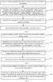
- FIG. 1 is a flow chart illustrating a method for adjusting an uplink transmission power of a terminal according to an exemplary embodiment of the present disclosure.
- the method is applied to a base station, that is, the method may be executed by the base station.
- the method includes the following.
- the sending capability information of the at least one antenna module of the terminal received by the base station may include sending capability information of a physical antenna module, a virtual antenna module or an antenna module combination of the terminal.
- the sending capability information may also include at least one of an identifier of the physical antenna module, an identifier of the virtual antenna module, and an identifier of the antenna module combination.
- a target uplink transmission power of the terminal is obtained based on the sending capability information of the at least one antenna module of the terminal.
- the target uplink transmission power may be obtained by increasing or reducing an uplink transmission power calculated based on a following formula, or obtained by increasing or reducing at least one parameter in the following formula and utilizing the at least one increased or reduced parameter.
- P CMAX represents a maximum transmission power of the terminal
- M PUSCH (i) represents the number of resource blocks (RB) used in a PUSCH transmission in the i-th subframe.
- P O_NOMINAL_PUSCH (j) represents a cell-specific parameter, which is related to a cell covered by the antenna module of the terminal.
- P O_UE_PUSCH(j) represents a terminal-specific parameter, which may be set with different values for different uplink transmission data packets.
- P O_NOMINAL_PUSCH (j) and P O_UE_PUSCH(j) may be indicated by a high layer signaling.
- ⁇ (j) represents a compensation amount of a path loss corresponding to the cell, and ⁇ (j) may be indicated by the high layer signaling.
- ⁇ (j) may also be referred to herein as a cell path compensation value since ⁇ (j) is related to the cell covered by the antenna module of the terminal.
- PL represents a loss compensation value of an open loop path obtained based on an estimation for a downlink by the terminal.
- ⁇ TF (i) represents a power adjustment value based on a modulation and coding scheme (MCS). Based on power adjustment for the MCS, a corresponding transmission power spectral density may be dynamically adjusted by the terminal according to a selected MCS.
- the MCS of the terminal is scheduled by the base station.
- the transmission power spectral density of the terminal may be quickly adjusted by setting a transmission MCS of the terminal, which may achieve an effect of quickly controlling the transmission power of the terminal.
- f(i) represents an adjustment value of a current power control of the PUSCH, which may be referred as a power adjustment value of the PUSCH.
- the power adjustment value of the PUSCH may be adjusted based on a transmitter power control (TPC) command on the PUSCH, and a detailed adjustment mode may be found in rule of 3GPPTS36.213.
- TPC transmitter power control
- the above transmission power of the terminal may be a conducted transmission power of the terminal, and a power radiated to a space (referred as a space radiation power) may have a certain loss.
- the terminal of the target uplink transmission power is notified.
- the base station may inform the terminal of the target uplink transmission power by sending a control signaling to the terminal.
- the control signaling may be, such as, any one of: a radio resource control (RRC) signaling, a media access control (MAC) control element (CE) signaling or a physical layer signaling.
- RRC radio resource control
- MAC media access control
- CE control element
- the control signaling may include an identifier of the terminal and the target uplink transmission power.
- the target uplink transmission power of the terminal is determined based on the sending capability information of the at least one antenna module of the terminal, and the target uplink transmission power is notified to the terminal, such that the terminal transmits a signal with the target uplink transmission power.
- a purpose of controlling the uplink transmission power of the terminal based on an actual transmission capability of the terminal is achieved, which may improve a data transmission efficiency of the terminal or save a power consumption of the terminal on the premise of ensuring the data transmission efficiency of the terminal.
- the sending capability information of the at least one of antenna module of the terminal includes at least one sending capability index.
- the at least one sending capability index may be a peak value of an effective isotropic radiated power (EIRP), an average value of the EIRP, a minimum value of the EIRP, an average value of a total radiated power (TRP), and a minimum value of the TRP.
- the sending capability indexes of the antenna module may be preset on the terminal before leaving the factory.
- the sending capability information of the at least one antenna module sent by the terminal and received by the base station may include an identifier of at least one antenna module, an identifier of at least one sending capability index of the at least one antenna module, and a value corresponding to the sending capability index.
- the sending capability information may also include an identifier of at least one antenna module combination, the identifier of the at least one sending capability index of the at least one antenna module, and the value corresponding to the sending capability index.
- FIG. 2 is a flow chart illustrating a method for adjusting an uplink transmission power of a terminal according to an exemplary embodiment of the present disclosure.
- obtaining the target uplink transmission power of the terminal based on the sending capability information of the at least one antenna module of the terminal includes the action at blocks 104 and 105.
- at block 104 at least one parameter of: a maximum transmission power, a nominal power, a cell path compensation value, a power adjustment value of a MCS and a power adjustment value of a PUSCH of the terminal is reduced in response to determining that a sending capability of the terminal is not lower than a first threshold based on the sending capability information of the at least one antenna module of the terminal.
- a preset value may be subtracted from the at least one parameter, or the at least one parameter may be multiplied by a preset coefficient greater than 0 and less than 1 when the at least one parameter is reduced. Reducing the maximum transmission power P aVAX of the terminal is taken as an example.
- a reduced P aVAX may be P aVAX - ⁇ P aVAX ( V _ xRP ) , where V _ xRP represents a value of a sending capability of the at least one antenna module of the terminal.
- V _ xRP may be one of the peak value of the EIRP, the average value of the EIRP, the minimum value of the EIRP, the average value of the TRP, and the minimum value of the TRP.
- V _ xRP The greater the value of V _ xRP , the stronger the sending capability of the terminal.
- a value of ⁇ P aVAX ( V _ xRP ) may be increased with increasing a value of V _ xFP, that is, the value of ⁇ P aVAX ( V _ xRP ) is positively correlated with the value of V _xRP.
- the reduced value of P aVAX may also be P aVAX ⁇ ⁇ P aVAX ( V _ xRP ).
- a value of ⁇ P aVAX ( V_xRP ) is reduced with increasing the value of V _xRP , that is, the value of ⁇ P aVAX ( V _ xFP) is negatively correlated with the value of V _xRP.
- the target uplink transmission power is calculated based on the at least one reduced parameter. For example, the target uplink transmission power may be obtained by substituting the at least one reduced parameter into the above formula.
- the sending capability of the terminal may be calculated based on the at least one sending capability index of the at least one antenna module of the terminal.
- the sending capability of the terminal may be a sum of the sending capabilities of all physical antenna modules of the terminal.
- the average value of the TRP of the at least one antenna module of the terminal is taken as an example. It is assumed that the terminal includes two antenna modules which are an antenna module 1 and an antenna module 2. An average value of a TRP of the antenna module 1 is 12dBm, an average value of a TRP of the antenna module 2 is 10dBm, and the sending ability of the terminal is 22dBm.
- the sending capability of the terminal may also be determined based on weight values of at least two sending capability indexes of the at least one antenna module of the terminal.
- the weight value is obtained by superimposing a weight value on each of the at least two sending capability indexes, and summing the at least two sending capability indexes after superimposing the weight values.
- the peak value of the EIRP and the minimum value of the TRP of the antenna module are taken as an example to calculate the sending capability of the terminal. It is assumed that the terminal includes the antenna module 1 and the antenna module 2.
- a peak value of an EIRP of the antenna module 1 is 14dBm
- a minimum value of a TRP of the antenna module 1 is 8dBm.
- a peak value of an EIRP of the antenna module 2 is 0.4, and a minimum value of a TRP of the antenna module 2 is 9dBm.
- FIG. 3 is a flow chart illustrating a method for adjusting an uplink transmission power of a terminal according to an exemplary embodiment of the present disclosure.
- obtaining the target uplink transmission power of the terminal based on the sending capability information of the at least one antenna module of the terminal may include: calculating the uplink transmission power of the terminal in response to determining that a sending capability of the terminal is not lower than a first threshold based on the sending capability information of the at least one antenna module of the terminal at block 106; and reducing the uplink transmission power, and taking the reduced uplink transmission power as the target uplink transmission power at block 107.
- the reduce uplink transmission power may be a value obtained by subtracting a preset value from the calculated uplink transmission power, or multiplying the calculated uplink power value by a preset coefficient greater than 0 and less than 1.
- the uplink transmission power P PUSCH (i) of the terminal may be reduced to P PUSCH (i)- ⁇ (V_xRP) 1 or P PUSCH (i) ⁇ ⁇ (V_xRP) by adjusting a factor ⁇ (V _xRP) 1 or a factor ⁇ (V_xRP) 1 .
- a value of ⁇ (V_xRP) 1 may be increased with increasing the value of V _ xRP, that is, the value of ⁇ (V_xRP) 1 is positively correlated with the value of V _xRP.
- a value of ⁇ (V_xRP) 1 is reduced with increasing the value of V _ xRP, that is, the value of ⁇ (V_xRP) 1 is negatively correlated with the value of V _ xRP.
- the above formula may be used for calculating the uplink transmission power of the terminal.
- FIG. 4 is a flow chart illustrating a method for adjusting an uplink transmission power of a terminal according to an exemplary embodiment of the present disclosure.
- obtaining the target uplink transmission power of the terminal based on the sending capability information of the at least one antenna module of the terminal may include: action at blocks 108 and 109.
- At block 108 at least one parameter of: a maximum transmission power of the terminal, a nominal power, a cell path compensation value, a power adjustment value of a MCS and a power adjustment value of a PUSCH is increased in response to determining that a sending capability of the terminal is not greater than a second threshold based on the sending capability information.
- the second threshold value may be equal to or lower than the first threshold value.
- the second threshold value may be set by an operator, or may be set by the base station based on a network layout situation of a certain network coverage area.
- Increasing the cell path compensation value ⁇ (j ) is taken as an example, and the increased value of ⁇ (j ) is ⁇ (j ) + ⁇ ⁇ (j )(V _ xRP ).
- V _ xRP represents a value of the sending capability of the at least one antenna module of the terminal.
- V _ xRP may be any one of the peak value of the EIR, the average value of the EIRP, the minimum value of the EIRP, the average value of the TRP, and the minimum value of the TRP.
- a value of ⁇ (j )(V _ xRP ) may be reduced with increasing the value of V _xRP, that is, the value of ⁇ ⁇ (j )(V _xRP ) is negatively correlated with the value of V _xRP.
- the increased value of ⁇ (j) may also be ⁇ (j ) ⁇ ⁇ a (j )( V _ xRP ).
- a value of ⁇ (j )( V _ xRP ) may be reduced with increasing the value of V _ xRP, that is, the value of ⁇ (j )( V _xRP ) is negatively correlated with the value of V _xRP.
- the target uplink transmission power is calculated based on the at least one increased parameter. For example, the target uplink transmission power may be obtained by substituting the increased value of at least one parameter into the above formula.
- FIG. 5 is a flow chart illustrating a method for adjusting an uplink transmission power of a terminal according to an exemplary embodiment of the present disclosure.
- obtaining the target uplink transmission power of the terminal based on the sending capability information of the at least one antenna module of the terminal may include: calculating the uplink transmission power of the terminal in response to determining that a sending capability of the terminal is not greater than a second threshold based on the sending capability information at block 110; and increasing the uplink transmission power, and taking the increased uplink transmission power as the target uplink transmission power at block 111.
- the increased uplink transmission power may be obtained by adding the calculated uplink transmission power by a preset value, or multiplying the calculated uplink power value by a preset coefficient greater than 1.
- the uplink transmission power P PUSCH (i) of the terminal may be increased to P PUSCH (i)- ⁇ (V _xRP) 2 or P PUSCH (i) ⁇ ⁇ (V _xRP) 2 by adjusting a factor ⁇ (V _xRP) 2 or a factor ⁇ (V_xRP) 2 .
- a value of ⁇ (V _xRP) 2 may be reduced with increasing the value of V _xRP, that is, the value of ⁇ (V_xRP) 2 is negatively correlated with the value of V _xRP.
- a value of ⁇ (V _ xRP) 2 may be reduced with increasing the value of V _ xRP, that is, the value of ⁇ (V_xRP) 2 is negatively correlated with the value of V _xRP.
- the above formula may be used for calculating the uplink transmission power of the terminal.
- the sending capability information of the at least one antenna module received by the base station is sent by the terminal via one of a radio resource control (RRC) signaling, a media access control (MAC) control element (CE) signaling or a physical layer signaling.
- RRC radio resource control
- MAC media access control
- CE control element
- a delay of the RRC signaling may reach 200 ms.
- a delay of the MAC CE signaling may reach tens of milliseconds.
- a delay of the physical layer signaling is usually within 10 ms. It may be seen that the RRC signaling has the largest delay, and the physical layer signaling has the smallest delay, but a delay overhead of the physical layer signaling is larger. Therefore, the terminal may select one of the three signalings to perform sending based on an actual requirement when sending the sending capability information of the at least one antenna module to the base station.
- FIG. 6 is a flow chart illustrating a method for adjusting an uplink transmission power of a terminal according to an exemplary embodiment of the present disclosure. The method is applied to the terminal. That is, the method may be executed by the terminal. As illustrated in FIG. 6 , the method includes the following.
- sending capability information of at least one antenna module of the terminal is sent to a base station.
- the terminal may send the sending capability information of the at least one antenna module of the terminal to the base station every time the terminal is initialized, for example, every time the terminal is turned on.
- the terminal may send the sending capability information of the at least one antenna module to the terminal via the RRC signaling, the MAC CE signaling or the physical layer signaling.
- a target uplink transmission power sent by the base station is received.
- the target uplink transmission power is obtained by the base station based on the sending capability information.
- the terminal may transmit an uplink signal with the target uplink transmission power after receiving the target uplink transmission power sent by the base station.
- the terminal may have multiple physical antenna modules.
- the at least one antenna module of the terminal may include a certain physical antenna module in the terminal, a virtual antenna module simulated by at least two physical antenna modules in the terminal, or an antenna module in the antenna module combination of the terminal.
- the terminal may send an identifier of the physical antenna module, an identifier of the virtual antenna module or an identifier of the antenna module combination simultaneously to the base station when sending the sending capability information of the at least one antenna module to the base station.
- the antenna module combination may include at least two physical antenna modules or at least two virtual antenna modules.
- the terminal may also send an identifier of the terminal to the base station simultaneously when sending the sending capability information of the antenna module to the base station, such that the base station may know the terminal to which the antenna module belongs.
- the terminal may send the sending capability information of the at least one antenna module of the terminal to the base station via the RRC signaling, the MAC CE signaling or the physical layer signaling.
- the terminal sends the sending capability information of the at least one antenna module of the terminal to the base station, such that the base station may determine the target uplink transmission power of the terminal based on the sending capability information.
- the terminal of the target uplink transmission power is notified, such that the terminal transmits the signal with the target uplink transmission power.
- the sending capability information sent by the at least one antenna module to the base station includes at least one of: a peak value of an EIRP, an average value of the EIRP, a minimum value of the EIRP, an average value of a TRP, and a minimum value of the TRP.
- the sending capability indexes of the antenna module of the terminal may be preset on the terminal before leaving the factory. The terminal may send the at least one sending capability index of the antenna module to the base station when sending the sending capability information of the at least one antenna module of the terminal to the base station.
- the sending capability information of at least one antenna module sent by the terminal to the base station may include an identifier of the antenna module, an identifier of the sending capability index and a value corresponding to the sending capability index, or may include an identifier of the antenna module combination, the identifier of the sending capability index and the value corresponding to the sending capability index.
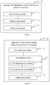
- FIG. 7 is a block diagram illustrating an apparatus for adjusting an uplink transmission power of a terminal according to an exemplary embodiment of the present disclosure.
- the apparatus 70 includes a first receiving module 71, a determining module 72, and a notification module 73.
- the first receiving module 71 is configured to receive sending capability information of at least one antenna module of the terminal.
- the determining module 72 is configured to obtain a target uplink transmission power of the terminal based on the sending capability information.
- the notification module 73 is configured to notify the terminal of the target uplink transmission power.
- FIG. 8 is a block diagram illustrating an apparatus for adjusting an uplink transmission power of a terminal according to an exemplary embodiment of the present disclosure.
- the determining module 72 includes: a first adjusting sub-module 721 and a first calculating sub-module 722.
- the first adjusting sub-module 721 is configured to reduce at least one parameter of: a maximum transmission power, a nominal power, a cell path compensation value, a power adjustment value of a MCS and a power adjustment value of a PUSCH of the terminal in response to determining that a sending capability of the terminal is not lower than a first threshold based on the sending capability information.
- the first calculating sub-module 722 is configured to calculate the target uplink transmission power based on the at least one parameter reduced.
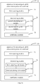
- FIG. 9 is a block diagram illustrating an apparatus for adjusting an uplink transmission power of a terminal according to an exemplary embodiment of the present disclosure.
- the determining module 72 may include: a second calculating sub-module 723 and a second adjusting sub-module 724.
- the second calculating sub-module 723 is configured to calculate the uplink transmission power of the terminal in response to determining that a sending capability of the terminal is not lower than a first threshold based on the sending capability information.
- the second adjusting sub-module 724 is configured to reduce the uplink transmission power, and to take the reduced uplink transmission power as the target uplink transmission power.
- FIG. 10 is a block diagram illustrating an apparatus for adjusting an uplink transmission power of a terminal according to an exemplary embodiment of the present disclosure.
- the determining module 72 may include: a third adjusting sub-module 725, and a third calculating sub-module 726.
- the third adjusting sub-module 725 is configured to increase at least one parameter of: a maximum transmission power of the terminal, a nominal power, a cell path compensation value, a power adjustment value of a MCS and a power adjustment value of a PUSCH in response to determining that a sending capability of the terminal is not greater than a second threshold based on the sending capability information.
- the third calculating sub-module 726 is configured to calculate the target uplink transmission power based on the at least one parameter increased.
- FIG. 11 is a block diagram illustrating an apparatus for adjusting an uplink transmission power of a terminal according to an exemplary embodiment of the present disclosure.
- the determining module 72 may include: a fourth calculating sub-module 727 and a fourth adjusting sub-module 728.
- the fourth calculating sub-module 727 is configured to calculate the uplink transmission power of the terminal in response to determining that a sending capability of the terminal is not greater than a second threshold based on the sending capability information.
- the fourth adjusting sub-module 728 is configured to increase the uplink transmission power, and to take the increased uplink transmission power as the target uplink transmission power.
- the sending capability information of the at least one antenna module of the terminal includes at least one of: a peak value of an EIRP, an average value of the EIRP, a minimum value of the EIRP, an average value of a TRP, and a minimum value of the TRP.
- the sending capability information of the at least one antenna module of the terminal is sent by the terminal via one of an RRC signaling, a MAC CE signaling or a physical layer signaling.
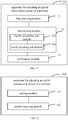
- FIG. 12 is a block diagram illustrating an apparatus for adjusting an uplink transmission power of a terminal according to an exemplary embodiment of the present disclosure.
- the apparatus 140 includes: a sending module 141 and a second receiving module 142.
- the sending module 141 is configured to send sending capability information of at least one antenna module of the terminal to a base station.
- the second receiving module 142 is configured to receive a target uplink transmission power sent by the base station.
- the target uplink transmission power is obtained by the base station based on the sending capability information.
- the sending capability information of the at least one antenna module of the terminal includes at least one of: a peak value of an EIRP, an average value of the EIRP, a minimum value of the EIRP, an average value of a TRP, and a minimum value of the TRP.
- the sending capability information of the at least one antenna module of the terminal may be sent by the terminal via at least one of: an RRC signaling, a MAC CE signaling or a physical layer signaling.
- FIG. 13 is a block diagram illustrating a device for adjusting an uplink transmission power of a terminal according to an exemplary embodiment of the present disclosure.
- the device 800 may be a mobile phone, a computer, a digital broadcasting terminal, a message sending and receiving equipment, a game controller, a tablet device, a medical device, a fitness equipment, a personal digital assistant or the like.
- the wearable device may be an intelligent watch, intelligent smart glasses, an intelligent bracelet, intelligent running shoes, etc.
- the device 800 may include one or more of: a processing component 802, a memory 804, a power component 806, a multimedia component 808, an audio component 810, an input/output (I/O) interface 812, a sensor component 814, and a communication component 816.
- a processing component 802 a memory 804, a power component 806, a multimedia component 808, an audio component 810, an input/output (I/O) interface 812, a sensor component 814, and a communication component 816.
- the processing component 802 typically controls overall operations of the device 800, such as the operations associated with display, telephone calls, data communications, camera operations, and recording operations.
- the processing component 802 may include one or more processors 802 to execute instructions to perform all or part of the steps in the above described methods.
- the processing component 802 may include one or more modules which facilitate the interaction between the processing component 802 and other components.
- the processing component 802 may include a multimedia module to facilitate the interaction between the multimedia component 808 and the processing component 802.
- the memory 804 is configured to store various types of data to support the operation of the device 800. Examples of such data include instructions for any applications or methods operated on the device 800 for performing the directional operation, contraction data, phonebook data, messages, pictures, video, etc.
- the memory 804 may be implemented using any type of volatile or non-volatile memory devices, or a combination thereof, such as a static random access memory (SRAM), an electrically erasable programmable read-only memory (EEPROM), an erasable programmable read-only memory (EPROM), a programmable read-only memory (PROM), a read-only memory (ROM), a magnetic memory, a flash memory, a magnetic or optical disk.
- SRAM static random access memory
- EEPROM electrically erasable programmable read-only memory
- EPROM erasable programmable read-only memory
- PROM programmable read-only memory
- ROM read-only memory
- magnetic memory a magnetic memory
- flash memory a flash memory
- the power component 806 is configured to provide power to various components of the device 800.
- the power component 806 may include a power management system, one or more power sources, and any other components associated with the generation, management, and distribution of power in the device 800.
- the multimedia component 808 includes a screen providing an output interface between the device 800 and the user.
- the screen may include a liquid crystal display (LCD) and a touch panel (TP). If the screen includes the touch panel, the screen may be implemented as a touch screen to receive input signals from the user.
- the touch panel includes one or more touch sensors to sense touches, swipes, and gestures on the touch panel. The touch sensors may not only sense a boundary of a touch or swipe action, but also sense a period of time and a pressure associated with the touch or swipe action.
- the multimedia component 808 includes a front camera and/or a rear camera. The front camera and the rear camera may receive an external multimedia datum while the device 800 is in an operation mode, such as an adjustment mode or a video mode. Each of the front camera and the rear camera may be a fixed optical lens system or have focus and optical zoom capability.
- the audio component 810 is configured to output and/or input audio signals.
- the audio component 810 includes a microphone ("MIC") for receiving an external audio signal when the device 800 is in an operation mode, such as a call mode, a recording mode, and a voice recognition mode.
- the received audio signal may be further stored in the memory 804 or transmitted via the communication component 816.
- the audio component 810 further includes a speaker to output audio signals.
- the I/O interface 812 is configured to provide an interface between the processing component 802 and peripheral interface modules, such as a keyboard, a click wheel, buttons, and the like.
- the buttons may include, but be not limited to, a home button, a volume button, a starting button, and a locking button.
- the sensor component 814 includes one or more sensors to provide status assessments of various aspects of the device 800.
- the sensor component 814 may detect an open/closed status of the device 800, relative positioning of components, e.g., the display and the keypad of the device 800, a change in position of the device 800 or a component of the device 800, a presence or absence of user contraction with the device 800, an orientation or an acceleration/deceleration of the device 800, and a change in temperature of the device 800.
- the sensor component 814 may include a proximity sensor for detecting the presence of nearby objects without any physical contact.
- the sensor component 814 may also include a light sensor, such as a CMOS (complementary metal-oxide-semiconductor)) or CCD (charge coupled device) image sensor, for use in imaging applications.
- CMOS complementary metal-oxide-semiconductor
- CCD charge coupled device
- the sensor component 814 may also include an accelerometer sensor, a gyroscope sensor, a magnetic sensor, a pressure sensor, or a temperature sensor.
- the communication component 816 is configured to facilitate communication, wired or wirelessly, between the device 800 and other devices.
- the device 800 may access a wireless network based on a communication standard, such as Wi-Fi, 2G, or 3G, or a combination thereof.
- the communication component 816 receives a broadcast signal or broadcast associated information from an external broadcast management system via a broadcast channel.
- the communication component 816 further includes a near field communication (NFC) module to facilitate short-range communications.
- the NFC module may be implemented based on a radio frequency identification (RFID) technology, an infrared data association (IrDA) technology, an ultra-wideband (UWB) technology, a Bluetooth (BT) technology, and other technologies.
- RFID radio frequency identification
- IrDA infrared data association
- UWB ultra-wideband
- BT Bluetooth
- the device 800 may be implemented with one or more application specific integrated circuits (ASICs), digital signal processors (DSPs), digital signal processing devices (DSPDs), programmable logic devices (PLDs), field programmable gate arrays (FPGAs), controllers, micro-controllers, microprocessors, or other electronic components, for performing the above methods.
- ASICs application specific integrated circuits
- DSPs digital signal processors
- DSPDs digital signal processing devices
- PLDs programmable logic devices
- FPGAs field programmable gate arrays
- controllers micro-controllers, microprocessors, or other electronic components, for performing the above methods.
- non-transitory computer readable storage medium including instructions, such as included in the memory 804, executed by the processor 820 in the device 800 for performing the above method.
- the non-transitory computer readable storage medium may be a ROM, a RAM, a CD-ROM, a magnetic tape, a floppy disc, an optical data storage device, and the like.
- FIG. 14 is a block diagram illustrating a device for adjusting an uplink transmission power of a terminal according to an exemplary embodiment of the present disclosure.
- the device 1900 may be provided as a server.
- the device 1900 includes a processing component 1922 and storage resources.
- the processing component 1922 further includes one or more processors.
- the storage resources are represented by a memory 1932, and configured to store instructions that may be executed by the processing component 1922.
- An application program stored in the memory 1932 may include one or more modules each corresponding to a set of instructions.
- the processing component 1922 is configured to execute instructions to execute the above method for adjusting the uplink transmission power of the terminal.
- the device 1900 may further include a power component 1926 configured to perform power management of the device 1900, a wired or wireless network interface 1950 configured to connect the apparatus 1900 to a network, and an input/output (I/O) interface 1958.
- the device 1900 may be performed based on an operating system stored in the memory 1932, such as a Windows ServerTM, a Mac OS XTM, a UnixTM, a LinuxTM, a FreeBSDTM or the like.
- a non-transitory computer-readable storage medium including instructions is also provided, such as the memory 1932 including instructions.
- the instructions may be executed by the processing component 1922 of the device 1900 to perform the above method.
- the non-temporary computer readable storage medium may be a ROM, a random access memory (RAM), a CD-ROM, a magnetic tape, a floppy disk, an optical data storage device, etc.
Landscapes
- Engineering & Computer Science (AREA)
- Computer Networks & Wireless Communication (AREA)
- Signal Processing (AREA)
- Databases & Information Systems (AREA)
- Mobile Radio Communication Systems (AREA)
Abstract
Description
- The present disclosure relates to a field of communication technologies, and more particularly to a method and an apparatus for adjusting an uplink transmission power of a terminal, and a storage medium.
- In the related art, an uplink transmission power of a terminal is mainly implemented based on measurement and feedback of a reference signal by the terminal. For example, the terminal feeds back a measured strength of a reference signal transmitted by a base station to the base station, and then the base station determines the uplink transmission power required by the terminal.
- To overcome defects existing in the related art, the present disclosure provides a method and an apparatus for adjusting an uplink transmission power of a terminal, and a storage medium.
- According to a first aspect of the present disclosure, there is provided a method for adjusting an uplink transmission power of a terminal. The method is applied to a base station. The method includes: receiving sending capability information of at least one antenna module of the terminal; obtaining a target uplink transmission power of the terminal based on the sending capability information; and notifying the terminal of the target uplink transmission power.
- Alternatively, obtaining the target uplink transmission power of the terminal based on the sending capability information includes: reducing at least one parameter of: a maximum transmission power, a nominal power, a cell path compensation value, a power adjustment value of a modulation and coding scheme (MCS) and a power adjustment value of a physical uplink shared channel (PUSCH) of the terminal in response to determining that a sending capability of the terminal is not lower than a first threshold based on the sending capability information; and calculating the target uplink transmission power based on the at least one parameter reduced.
- Alternatively, obtaining the target uplink transmission power of the terminal based on the sending capability information includes: calculating the uplink transmission power of the terminal in response to determining that a sending capability of the terminal is not lower than a first threshold based on the sending capability information; and reducing the uplink transmission power, and taking the reduced uplink transmission power as the target uplink transmission power.
- Alternatively, obtaining the target uplink transmission power of the terminal based on the sending capability information includes: increasing at least one parameter of: a maximum transmission power of the terminal, a nominal power, a cell path compensation value, a power adjustment value of a MCS and a power adjustment value of a PUSCH in response to determining that a sending capability of the terminal is not greater than a second threshold based on the sending capability information; and calculating the target uplink transmission power based on the at least one parameter increased.
- Alternatively, obtaining the target uplink transmission power of the terminal based on the sending capability information includes: calculating the uplink transmission power of the terminal in response to determining that a sending capability of the terminal is not greater than a second threshold based on the sending capability information; and increasing the uplink transmission power, and taking the increased uplink transmission power as the target uplink transmission power.
- Alternatively, the sending capability information includes at least one of: a peak value of an effective isotropic radiated power (EIRP), an average value of the EIRP, a minimum value of the EIRP, an average value of a total radiated power (TRP), and a minimum value of the TRP.
- Alternatively, the sending capability information is sent by the terminal via one of a radio resource control (RRC) signaling, a media access control (MAC) control element (CE) signaling or a physical layer signaling.
- According to a second aspect of the present disclosure, there is provided a method for adjusting an uplink transmission power of a terminal, which is applied to the terminal. The method includes: sending sending capability information of at least one antenna module of the terminal to a base station; and receiving a target uplink transmission power sent by the base station, the target uplink transmission power being obtained by the base station based on the sending capability information.
- Alternatively, the sending capability information sent by the at least one antenna module includes at least one of: a peak value of an EIRP, an average value of the EIRP, a minimum value of the EIRP, an average value of a TRP, and a minimum value of the TRP.
- Alternatively, transmitting the sending capability information of the at least one antenna module of the terminal to the base station includes: sending the sending capability information via at least one of: an RRC signaling, a MAC CE signaling or a physical layer signaling.
- According to a third aspect of the present disclosure, there is provided an apparatus for adjusting an uplink transmission power of a terminal. The apparatus is applied to a base station. The apparatus includes: a first receiving module, a determining module, and a notification module. The first receiving module is configured to receive sending capability information of at least one antenna module of the terminal. The determining module is configured to obtain a target uplink transmission power of the terminal based on the sending capability information. The notification module is configured to notify the terminal of the target uplink transmission power.
- Alternatively, the determining module includes: a first adjusting sub-module, and a first calculating sub-module. The first adjusting sub-module is configured to reduce at least one parameter of: a maximum transmission power, a nominal power, a cell path compensation value, a power adjustment value of a MCS and a power adjustment value of a PUSCH of the terminal in response to determining that a sending capability of the terminal is not lower than a first threshold based on the sending capability information. The first calculating sub-module is configured to calculate the target uplink transmission power based on the at least one parameter reduced.
- Alternatively, the determining module includes: a second calculating sub-module, and a second adjusting sub-module. The second calculating sub-module is configured to calculate the uplink transmission power of the terminal in response to determining that a sending capability of the terminal is not lower than a first threshold based on the sending capability information. The second adjusting sub-module is configured to reduce the uplink transmission power, and to take the reduced uplink transmission power as the target uplink transmission power.
- Alternatively, the determining module includes: a third adjusting sub-module, and a third calculating sub-module. The third adjusting sub-module is configured to increase at least one parameter of: a maximum transmission power of the terminal, a nominal power, a cell path compensation value, a power adjustment value of a MCS and a power adjustment value of a PUSCH in response to determining that a sending capability of the terminal is not greater than a second threshold based on the sending capability information. The third calculating sub-module is configured to calculate the target uplink transmission power based on the at least one parameter increased.
- Alternatively, the determining module includes: a fourth calculating sub-module, and a fourth adjusting sub-module. The fourth calculating sub-module is configured to calculate the uplink transmission power of the terminal in response to determining that a sending capability of the terminal is not greater than a second threshold based on the sending capability information. The fourth adjusting sub-module is configured to increase the uplink transmission power, and to take the increased uplink transmission power as the target uplink transmission power.
- Alternatively, the sending capability information includes at least one of: a peak value of an EIRP, an average value of the EIRP, a minimum value of the EIRP, an average value of a TRP, and a minimum value of the TRP.
- Alternatively, the sending capability information is sent by the terminal via one of an RRC signaling, a MAC CE signaling or a physical layer signaling.
- According to a fourth aspect of the present disclosure, there is provided an apparatus for adjusting an uplink transmission power of a terminal. The apparatus is applied to the terminal. The apparatus includes: a sending module, and a second receiving module. The sending module is configured to send sending capability information of at least one antenna module of the terminal to a base station. The second receiving module is configured to receive a target uplink transmission power sent by the base station. The target uplink transmission power is obtained by the base station based on the sending capability information.
- Alternatively, the sending capability information of the at least one antenna module includes at least one of: a peak value of an EIRP, an average value of the EIRP, a minimum value of the EIRP, an average value of a TRP, and a minimum value of the TRP.
- Alternatively, the sending module is configured to: send the sending capability information via at least one of: an RRC signaling, a MAC CE signaling or a physical layer signaling.
- According to a fifth aspect of the present disclosure, there is provided a device for adjusting an uplink transmission power of a terminal. The device is applied to a base station. The device includes: a processor and a memory. The memory is configured to store instructions executable by the processor. The processor is configured to: receive sending capability information of at least one antenna module of the terminal; obtain a target uplink transmission power of the terminal based on the sending capability information; and notify the terminal of the target uplink transmission power.
- According to a sixth aspect of the present disclosure, there is provided a non-transitory computer readable storage medium. Instructions in the storage medium are configured to enable the processor to perform the method according to the first aspect of the present disclosure when executed by a processor.
- According to a seventh aspect of the present disclosure, there is provided a device for adjusting an uplink transmission power of a terminal. The device is applied to the terminal. The device includes: a processor and a memory. The memory is configured to store instructions executable by the processor. The processor is configured to: send sending capability information of at least one antenna module of the terminal to a base station; and receive a target uplink transmission power sent by the base station, the target uplink transmission power being obtained by the base station based on the sending capability information.
- According to an eighth aspect of the present disclosure, there is provided a non-transitory computer readable storage medium. Instructions in the storage medium are configured to enable the processor to perform the method according to the second aspect when executed by a processor.
- The technical solution provided by embodiments of the present disclosure may include following advantageous effects.
- With the method for adjusting the uplink transmission power of the terminal of embodiments, the target uplink transmission power of the terminal is determined based on the sending capability information of the at least one antenna module of the terminal, and the target uplink transmission power is notified to the terminal, such that the terminal transmits a signal with the target uplink transmission power. In this way, a purpose of controlling the uplink transmission power of the terminal based on an actual transmission capability of the terminal is achieved, which may improve a data transmission efficiency of the terminal or save a power consumption of the terminal on the premise of ensuring the data transmission efficiency of the terminal.
- It is to be understood that both the foregoing general description and the following detailed description are exemplary and explanatory only, and are not restrictive of the present disclosure.
- The accompanying drawings, which are incorporated in and constitute a part of this specification, illustrate embodiments consistent with the present disclosure, and serve to explain the principle of the present disclosure together with the specification.
-
FIG. 1 is a flow chart illustrating a method for adjusting an uplink transmission power of a terminal according to an exemplary embodiment of the present disclosure. -
FIG. 2 is a flow chart illustrating a method for adjusting an uplink transmission power of a terminal according to an exemplary embodiment of the present disclosure. -
FIG. 3 is a flow chart illustrating a method for adjusting an uplink transmission power of a terminal according to an exemplary embodiment of the present disclosure. -
FIG. 4 is a flow chart illustrating a method for adjusting an uplink transmission power of a terminal according to an exemplary embodiment of the present disclosure. -
FIG. 5 is a flow chart illustrating a method for adjusting an uplink transmission power of a terminal according to an exemplary embodiment of the present disclosure. -
FIG. 6 is a flow chart illustrating a method for adjusting an uplink transmission power of a terminal according to an exemplary embodiment of the present disclosure. -
FIG. 7 is a block diagram illustrating an apparatus for adjusting an uplink transmission power of a terminal according to an exemplary embodiment of the present disclosure. -
FIG. 8 is a block diagram illustrating an apparatus for adjusting an uplink transmission power of a terminal according to an exemplary embodiment of the present disclosure. -
FIG. 9 is a block diagram illustrating an apparatus for adjusting an uplink transmission power of a terminal according to an exemplary embodiment of the present disclosure. -
FIG. 10 is a block diagram illustrating an apparatus for adjusting an uplink transmission power of a terminal according to an exemplary embodiment of the present disclosure. -
FIG. 11 is a block diagram illustrating an apparatus for adjusting an uplink transmission power of a terminal according to an exemplary embodiment of the present disclosure. -
FIG. 12 is a block diagram illustrating an apparatus for adjusting an uplink transmission power of a terminal according to an exemplary embodiment of the present disclosure. -
FIG. 13 is a block diagram illustrating a device for adjusting an uplink transmission power of a terminal according to an exemplary embodiment of the present disclosure. -
FIG. 14 is a block diagram illustrating a device for adjusting an uplink transmission power of a terminal according to an exemplary embodiment of the present disclosure. - Exemplary embodiments will be described in detail herein, examples of which are illustrated in the accompanying drawings. When the following description refers to the accompanying drawings, the same or similar elements may be denoted by the same numerals in different accompanying drawings, unless otherwise indicated. The implementations described in the following exemplary embodiments do not represent all implementations consistent with the present disclosure. Instead, they are merely examples of apparatuses and methods consistent with aspects of the present disclosure as detailed in the appended claims.
-
FIG. 1 is a flow chart illustrating a method for adjusting an uplink transmission power of a terminal according to an exemplary embodiment of the present disclosure. The method is applied to a base station, that is, the method may be executed by the base station. As illustrated inFIG. 1 , the method includes the following. - At
block 101, sending capability information of at least one antenna module of the terminal is received. - In a possible implementation, the sending capability information of the at least one antenna module of the terminal received by the base station may include sending capability information of a physical antenna module, a virtual antenna module or an antenna module combination of the terminal. The sending capability information may also include at least one of an identifier of the physical antenna module, an identifier of the virtual antenna module, and an identifier of the antenna module combination.
- At
block 102, a target uplink transmission power of the terminal is obtained based on the sending capability information of the at least one antenna module of the terminal. - Description will be made below to the method for calculating the uplink transmission power of the terminal based on a method for calculating an uplink transmission power of the terminal in the i-th subframe on a physical uplink shared channel (PUSCH). The target uplink transmission power may be obtained by increasing or reducing an uplink transmission power calculated based on a following formula, or obtained by increasing or reducing at least one parameter in the following formula and utilizing the at least one increased or reduced parameter.
- A transmission power PPUSCH(i) of the terminal in the i-th subframe on the PUSCH may be obtained by:

- In the formula, PCMAX represents a maximum transmission power of the terminal, and MPUSCH(i) represents the number of resource blocks (RB) used in a PUSCH transmission in the i-th subframe.
- In the formula, PO_PUSCH(j)=PO_NOMINAL_PUSCH(j)+PO_UE_PUSCH(j) represents a semi-static setting power reference value. PO_NOMINAL_PUSCH(j) represents a cell-specific parameter, which is related to a cell covered by the antenna module of the terminal. PO_UE_PUSCH(j) represents a terminal-specific parameter, which may be set with different values for different uplink transmission data packets. PO_NOMINAL_PUSCH(j) and PO_UE_PUSCH(j) may be indicated by a high layer signaling. In addition, the parameter j is related to the upstream transmission data packet, that is, j = 0 when a semi-persistent data packet is transmitted; j = 1 when a data packet with a dynamic scheduling permission is transmitted; and j =2 when a data packet randomly accessing a response permission is transmitted.
- In the formula, α(j) represents a compensation amount of a path loss corresponding to the cell, and α (j) may be indicated by the high layer signaling. α(j) takes a value in {0,0.4,0.5,0.6,0.7,0.8,0.9,1} when j=0 or j=1, and α (j) =1 when j =2. α (j) may also be referred to herein as a cell path compensation value since α (j) is related to the cell covered by the antenna module of the terminal.
- In the formula, PL represents a loss compensation value of an open loop path obtained based on an estimation for a downlink by the terminal.
- In the formula, ΔTF(i) represents a power adjustment value based on a modulation and coding scheme (MCS). Based on power adjustment for the MCS, a corresponding transmission power spectral density may be dynamically adjusted by the terminal according to a selected MCS. The MCS of the terminal is scheduled by the base station. The transmission power spectral density of the terminal may be quickly adjusted by setting a transmission MCS of the terminal, which may achieve an effect of quickly controlling the transmission power of the terminal.
- In the formula, f(i) represents an adjustment value of a current power control of the PUSCH, which may be referred as a power adjustment value of the PUSCH. The power adjustment value of the PUSCH may be adjusted based on a transmitter power control (TPC) command on the PUSCH, and a detailed adjustment mode may be found in rule of 3GPPTS36.213.
- The above transmission power of the terminal may be a conducted transmission power of the terminal, and a power radiated to a space (referred as a space radiation power) may have a certain loss.
- At
block 103, the terminal of the target uplink transmission power is notified. - In a possible implementation, the base station may inform the terminal of the target uplink transmission power by sending a control signaling to the terminal. The control signaling may be, such as, any one of: a radio resource control (RRC) signaling, a media access control (MAC) control element (CE) signaling or a physical layer signaling. The control signaling may include an identifier of the terminal and the target uplink transmission power.
- With the method for adjusting the uplink transmission power of the terminal of embodiments, the target uplink transmission power of the terminal is determined based on the sending capability information of the at least one antenna module of the terminal, and the target uplink transmission power is notified to the terminal, such that the terminal transmits a signal with the target uplink transmission power. In this way, a purpose of controlling the uplink transmission power of the terminal based on an actual transmission capability of the terminal is achieved, which may improve a data transmission efficiency of the terminal or save a power consumption of the terminal on the premise of ensuring the data transmission efficiency of the terminal.
- In a possible implementation, the sending capability information of the at least one of antenna module of the terminal includes at least one sending capability index. The at least one sending capability index may be a peak value of an effective isotropic radiated power (EIRP), an average value of the EIRP, a minimum value of the EIRP, an average value of a total radiated power (TRP), and a minimum value of the TRP. For example, the sending capability indexes of the antenna module may be preset on the terminal before leaving the factory. The sending capability information of the at least one antenna module sent by the terminal and received by the base station may include an identifier of at least one antenna module, an identifier of at least one sending capability index of the at least one antenna module, and a value corresponding to the sending capability index. The sending capability information may also include an identifier of at least one antenna module combination, the identifier of the at least one sending capability index of the at least one antenna module, and the value corresponding to the sending capability index.
-
FIG. 2 is a flow chart illustrating a method for adjusting an uplink transmission power of a terminal according to an exemplary embodiment of the present disclosure. As illustrated inFIG. 2 , in the method, obtaining the target uplink transmission power of the terminal based on the sending capability information of the at least one antenna module of the terminal includes the action atblocks block 104, at least one parameter of: a maximum transmission power, a nominal power, a cell path compensation value, a power adjustment value of a MCS and a power adjustment value of a PUSCH of the terminal is reduced in response to determining that a sending capability of the terminal is not lower than a first threshold based on the sending capability information of the at least one antenna module of the terminal. A preset value may be subtracted from the at least one parameter, or the at least one parameter may be multiplied by a preset coefficient greater than 0 and less than 1 when the at least one parameter is reduced. Reducing the maximum transmission power PaVAX of the terminal is taken as an example. A reduced PaVAX may be PaVAX - ΔPaVAX (V _ xRP) , where V _ xRP represents a value of a sending capability of the at least one antenna module of the terminal. For example, V _ xRP may be one of the peak value of the EIRP, the average value of the EIRP, the minimum value of the EIRP, the average value of the TRP, and the minimum value of the TRP. The greater the value of V _ xRP , the stronger the sending capability of the terminal. A value of ΔPaVAX (V _ xRP) may be increased with increasing a value of V _ xFP, that is, the value of ΔPaVAX (V _ xRP) is positively correlated with the value of V _xRP. The reduced value of PaVAX may also be PaVAX × βPaVAX (V _ xRP). A value of βPaVAX (V_xRP) is reduced with increasing the value of V _xRP, that is, the value of βPaVAX (V _ xFP) is negatively correlated with the value of V _xRP. Atblock 105, the target uplink transmission power is calculated based on the at least one reduced parameter. For example, the target uplink transmission power may be obtained by substituting the at least one reduced parameter into the above formula. - In a possible implementation, the sending capability of the terminal may be calculated based on the at least one sending capability index of the at least one antenna module of the terminal. The sending capability of the terminal may be a sum of the sending capabilities of all physical antenna modules of the terminal. The average value of the TRP of the at least one antenna module of the terminal is taken as an example. It is assumed that the terminal includes two antenna modules which are an antenna module 1 and an antenna module 2. An average value of a TRP of the antenna module 1 is 12dBm, an average value of a TRP of the antenna module 2 is 10dBm, and the sending ability of the terminal is 22dBm.
- In a possible implementation, the sending capability of the terminal may also be determined based on weight values of at least two sending capability indexes of the at least one antenna module of the terminal. The weight value is obtained by superimposing a weight value on each of the at least two sending capability indexes, and summing the at least two sending capability indexes after superimposing the weight values. The peak value of the EIRP and the minimum value of the TRP of the antenna module are taken as an example to calculate the sending capability of the terminal. It is assumed that the terminal includes the antenna module 1 and the antenna module 2. A peak value of an EIRP of the antenna module 1 is 14dBm, and a minimum value of a TRP of the antenna module 1 is 8dBm. A peak value of an EIRP of the antenna module 2 is 0.4, and a minimum value of a TRP of the antenna module 2 is 9dBm. A weight value corresponding to the peak value of the EIRP is 0.4, and a weight value corresponding to the minimum value of the TRP is 0.6. Therefore, the sending capability of the terminal is (14 × 0. 4 + 8 × 0. 6) + (13 × 0. 4 + 9 × 0. 6) = 21dBm.
-
FIG. 3 is a flow chart illustrating a method for adjusting an uplink transmission power of a terminal according to an exemplary embodiment of the present disclosure. As illustrated inFIG. 3 , in the method, obtaining the target uplink transmission power of the terminal based on the sending capability information of the at least one antenna module of the terminal may include: calculating the uplink transmission power of the terminal in response to determining that a sending capability of the terminal is not lower than a first threshold based on the sending capability information of the at least one antenna module of the terminal atblock 106; and reducing the uplink transmission power, and taking the reduced uplink transmission power as the target uplink transmission power atblock 107. The reduce uplink transmission power may be a value obtained by subtracting a preset value from the calculated uplink transmission power, or multiplying the calculated uplink power value by a preset coefficient greater than 0 and less than 1. For example, the uplink transmission power PPUSCH(i) of the terminal may be reduced to PPUSCH(i)- Δ (V_xRP)1 or PPUSCH(i) × β (V_xRP) by adjusting a factor Δ (V _xRP)1 or a factor β (V_xRP)1. A value of Δ (V_xRP)1 may be increased with increasing the value of V _ xRP, that is, the value of Δ (V_xRP)1 is positively correlated with the value of V _xRP. A value of β (V_xRP)1 is reduced with increasing the value of V _ xRP, that is, the value of β (V_xRP)1 is negatively correlated with the value of V _ xRP. The above formula may be used for calculating the uplink transmission power of the terminal. -
FIG. 4 is a flow chart illustrating a method for adjusting an uplink transmission power of a terminal according to an exemplary embodiment of the present disclosure. As illustrated inFIG. 4 , in the method, obtaining the target uplink transmission power of the terminal based on the sending capability information of the at least one antenna module of the terminal may include: action atblocks block 108, at least one parameter of: a maximum transmission power of the terminal, a nominal power, a cell path compensation value, a power adjustment value of a MCS and a power adjustment value of a PUSCH is increased in response to determining that a sending capability of the terminal is not greater than a second threshold based on the sending capability information. Any one of the above parameters may be increased by, such as, adding a preset value to the parameter, or multiplying the parameter by a preset coefficient greater than 1. The second threshold value may be equal to or lower than the first threshold value. The second threshold value may be set by an operator, or may be set by the base station based on a network layout situation of a certain network coverage area. Increasing the cell path compensation value α(j ) is taken as an example, and the increased value of α(j ) is α(j )+Δα(j )(V _ xRP). V _ xRP represents a value of the sending capability of the at least one antenna module of the terminal. For example, V_xRP may be any one of the peak value of the EIR, the average value of the EIRP, the minimum value of the EIRP, the average value of the TRP, and the minimum value of the TRP. The greater the value of V _ xRP, the stronger the sending capability of the terminal is. A value of Δλ(j )(V _ xRP) may be reduced with increasing the value of V _xRP, that is, the value of Δα(j )(V _xRP) is negatively correlated with the value of V _xRP. The increased value of α(j) may also be α(j ) × βa (j )(V _ xRP). A value of βα(j )(V _ xRP) may be reduced with increasing the value of V _ xRP, that is, the value of βα(j )(V _xRP) is negatively correlated with the value of V _xRP. Atblock 109, the target uplink transmission power is calculated based on the at least one increased parameter. For example, the target uplink transmission power may be obtained by substituting the increased value of at least one parameter into the above formula. -
FIG. 5 is a flow chart illustrating a method for adjusting an uplink transmission power of a terminal according to an exemplary embodiment of the present disclosure. As illustrated inFIG. 5 , in the method, obtaining the target uplink transmission power of the terminal based on the sending capability information of the at least one antenna module of the terminal may include: calculating the uplink transmission power of the terminal in response to determining that a sending capability of the terminal is not greater than a second threshold based on the sending capability information atblock 110; and increasing the uplink transmission power, and taking the increased uplink transmission power as the target uplink transmission power atblock 111. The increased uplink transmission power may be obtained by adding the calculated uplink transmission power by a preset value, or multiplying the calculated uplink power value by a preset coefficient greater than 1. For example, the uplink transmission power PPUSCH(i) of the terminal may be increased to PPUSCH(i)- Δ (V _xRP)2 or PPUSCH(i) × β (V _xRP)2 by adjusting a factor Δ (V _xRP)2 or a factor β (V_xRP)2. A value of Δ (V _xRP)2 may be reduced with increasing the value of V _xRP, that is, the value of Δ(V_xRP)2 is negatively correlated with the value of V _xRP. A value of β(V_xRP)2 may be reduced with increasing the value of V _ xRP, that is, the value of β(V_xRP)2 is negatively correlated with the value of V _xRP. The above formula may be used for calculating the uplink transmission power of the terminal. - In a possible implementation, the sending capability information of the at least one antenna module received by the base station is sent by the terminal via one of a radio resource control (RRC) signaling, a media access control (MAC) control element (CE) signaling or a physical layer signaling. A delay of the RRC signaling may reach 200 ms. A delay of the MAC CE signaling may reach tens of milliseconds. A delay of the physical layer signaling is usually within 10 ms. It may be seen that the RRC signaling has the largest delay, and the physical layer signaling has the smallest delay, but a delay overhead of the physical layer signaling is larger. Therefore, the terminal may select one of the three signalings to perform sending based on an actual requirement when sending the sending capability information of the at least one antenna module to the base station.
-
FIG. 6 is a flow chart illustrating a method for adjusting an uplink transmission power of a terminal according to an exemplary embodiment of the present disclosure. The method is applied to the terminal. That is, the method may be executed by the terminal. As illustrated inFIG. 6 , the method includes the following. - At
block 601, sending capability information of at least one antenna module of the terminal is sent to a base station. - In a possible implementation, the terminal may send the sending capability information of the at least one antenna module of the terminal to the base station every time the terminal is initialized, for example, every time the terminal is turned on.
- In a possible implementation, the terminal may send the sending capability information of the at least one antenna module to the terminal via the RRC signaling, the MAC CE signaling or the physical layer signaling.
- At
block 602, a target uplink transmission power sent by the base station is received. The target uplink transmission power is obtained by the base station based on the sending capability information. - In a possible implementation, the terminal may transmit an uplink signal with the target uplink transmission power after receiving the target uplink transmission power sent by the base station.
- In a possible implementation, the terminal may have multiple physical antenna modules. The at least one antenna module of the terminal may include a certain physical antenna module in the terminal, a virtual antenna module simulated by at least two physical antenna modules in the terminal, or an antenna module in the antenna module combination of the terminal. The terminal may send an identifier of the physical antenna module, an identifier of the virtual antenna module or an identifier of the antenna module combination simultaneously to the base station when sending the sending capability information of the at least one antenna module to the base station. The antenna module combination may include at least two physical antenna modules or at least two virtual antenna modules.
- In a possible implementation, the terminal may also send an identifier of the terminal to the base station simultaneously when sending the sending capability information of the antenna module to the base station, such that the base station may know the terminal to which the antenna module belongs.
- In a possible implementation, the terminal may send the sending capability information of the at least one antenna module of the terminal to the base station via the RRC signaling, the MAC CE signaling or the physical layer signaling.
- With the method for adjusting the uplink transmission power of the terminal of this embodiment, the terminal sends the sending capability information of the at least one antenna module of the terminal to the base station, such that the base station may determine the target uplink transmission power of the terminal based on the sending capability information. The terminal of the target uplink transmission power is notified, such that the terminal transmits the signal with the target uplink transmission power. In this way, the purpose of controlling the uplink transmission power of the terminal is implemented based on the actual sending capability of the terminal, the data transmission efficiency of the terminal is improved, or the power consumption of the terminal is saved on the premise of ensuring the data transmission efficiency of the terminal.
- In a possible implementation, the sending capability information sent by the at least one antenna module to the base station includes at least one of: a peak value of an EIRP, an average value of the EIRP, a minimum value of the EIRP, an average value of a TRP, and a minimum value of the TRP. For example, the sending capability indexes of the antenna module of the terminal may be preset on the terminal before leaving the factory. The terminal may send the at least one sending capability index of the antenna module to the base station when sending the sending capability information of the at least one antenna module of the terminal to the base station. For example, the sending capability information of at least one antenna module sent by the terminal to the base station may include an identifier of the antenna module, an identifier of the sending capability index and a value corresponding to the sending capability index, or may include an identifier of the antenna module combination, the identifier of the sending capability index and the value corresponding to the sending capability index.
-
FIG. 7 is a block diagram illustrating an apparatus for adjusting an uplink transmission power of a terminal according to an exemplary embodiment of the present disclosure. As illustrated inFIG. 7 , theapparatus 70 includes afirst receiving module 71, a determiningmodule 72, and anotification module 73. Thefirst receiving module 71 is configured to receive sending capability information of at least one antenna module of the terminal. The determiningmodule 72 is configured to obtain a target uplink transmission power of the terminal based on the sending capability information. Thenotification module 73 is configured to notify the terminal of the target uplink transmission power. -
FIG. 8 is a block diagram illustrating an apparatus for adjusting an uplink transmission power of a terminal according to an exemplary embodiment of the present disclosure. As illustrated inFIG. 8 , in theapparatus 80, the determiningmodule 72 includes: a first adjustingsub-module 721 and a first calculatingsub-module 722. Thefirst adjusting sub-module 721 is configured to reduce at least one parameter of: a maximum transmission power, a nominal power, a cell path compensation value, a power adjustment value of a MCS and a power adjustment value of a PUSCH of the terminal in response to determining that a sending capability of the terminal is not lower than a first threshold based on the sending capability information. The first calculatingsub-module 722 is configured to calculate the target uplink transmission power based on the at least one parameter reduced. -
FIG. 9 is a block diagram illustrating an apparatus for adjusting an uplink transmission power of a terminal according to an exemplary embodiment of the present disclosure. As illustrated inFIG. 9 , in theapparatus 90, the determiningmodule 72 may include: a second calculatingsub-module 723 and asecond adjusting sub-module 724. The second calculatingsub-module 723 is configured to calculate the uplink transmission power of the terminal in response to determining that a sending capability of the terminal is not lower than a first threshold based on the sending capability information. Thesecond adjusting sub-module 724 is configured to reduce the uplink transmission power, and to take the reduced uplink transmission power as the target uplink transmission power. -
FIG. 10 is a block diagram illustrating an apparatus for adjusting an uplink transmission power of a terminal according to an exemplary embodiment of the present disclosure. As illustrated inFIG. 10 , in theapparatus 120, the determiningmodule 72 may include: a third adjusting sub-module 725, and a third calculatingsub-module 726. Thethird adjusting sub-module 725 is configured to increase at least one parameter of: a maximum transmission power of the terminal, a nominal power, a cell path compensation value, a power adjustment value of a MCS and a power adjustment value of a PUSCH in response to determining that a sending capability of the terminal is not greater than a second threshold based on the sending capability information. The third calculating sub-module 726 is configured to calculate the target uplink transmission power based on the at least one parameter increased. -
FIG. 11 is a block diagram illustrating an apparatus for adjusting an uplink transmission power of a terminal according to an exemplary embodiment of the present disclosure. As illustrated inFIG. 11 , in theapparatus 130, the determiningmodule 72 may include: a fourth calculating sub-module 727 and a fourth adjustingsub-module 728. The fourth calculating sub-module 727 is configured to calculate the uplink transmission power of the terminal in response to determining that a sending capability of the terminal is not greater than a second threshold based on the sending capability information. The fourth adjusting sub-module 728 is configured to increase the uplink transmission power, and to take the increased uplink transmission power as the target uplink transmission power. - In a possible implementation, the sending capability information of the at least one antenna module of the terminal includes at least one of: a peak value of an EIRP, an average value of the EIRP, a minimum value of the EIRP, an average value of a TRP, and a minimum value of the TRP.
- In a possible implementation, the sending capability information of the at least one antenna module of the terminal is sent by the terminal via one of an RRC signaling, a MAC CE signaling or a physical layer signaling.
-
FIG. 12 is a block diagram illustrating an apparatus for adjusting an uplink transmission power of a terminal according to an exemplary embodiment of the present disclosure. As illustrated inFIG. 12 , theapparatus 140 includes: a sendingmodule 141 and asecond receiving module 142. The sendingmodule 141 is configured to send sending capability information of at least one antenna module of the terminal to a base station. Thesecond receiving module 142 is configured to receive a target uplink transmission power sent by the base station. The target uplink transmission power is obtained by the base station based on the sending capability information. - In a possible implementation, the sending capability information of the at least one antenna module of the terminal includes at least one of: a peak value of an EIRP, an average value of the EIRP, a minimum value of the EIRP, an average value of a TRP, and a minimum value of the TRP.
- In a possible implementation, the sending capability information of the at least one antenna module of the terminal may be sent by the terminal via at least one of: an RRC signaling, a MAC CE signaling or a physical layer signaling.
- With regard to the apparatuses in the above embodiments, a detailed manner of each module performing operations is described in detail in embodiments related to the method, which is not elaborated here.
-
FIG. 13 is a block diagram illustrating a device for adjusting an uplink transmission power of a terminal according to an exemplary embodiment of the present disclosure. For example, thedevice 800 may be a mobile phone, a computer, a digital broadcasting terminal, a message sending and receiving equipment, a game controller, a tablet device, a medical device, a fitness equipment, a personal digital assistant or the like. The wearable device may be an intelligent watch, intelligent smart glasses, an intelligent bracelet, intelligent running shoes, etc. - As illustrated in
FIG. 13 , thedevice 800 may include one or more of: aprocessing component 802, amemory 804, apower component 806, amultimedia component 808, anaudio component 810, an input/output (I/O)interface 812, asensor component 814, and acommunication component 816. - The
processing component 802 typically controls overall operations of thedevice 800, such as the operations associated with display, telephone calls, data communications, camera operations, and recording operations. Theprocessing component 802 may include one ormore processors 802 to execute instructions to perform all or part of the steps in the above described methods. Moreover, theprocessing component 802 may include one or more modules which facilitate the interaction between theprocessing component 802 and other components. For example, theprocessing component 802 may include a multimedia module to facilitate the interaction between themultimedia component 808 and theprocessing component 802. - The
memory 804 is configured to store various types of data to support the operation of thedevice 800. Examples of such data include instructions for any applications or methods operated on thedevice 800 for performing the directional operation, contraction data, phonebook data, messages, pictures, video, etc. Thememory 804 may be implemented using any type of volatile or non-volatile memory devices, or a combination thereof, such as a static random access memory (SRAM), an electrically erasable programmable read-only memory (EEPROM), an erasable programmable read-only memory (EPROM), a programmable read-only memory (PROM), a read-only memory (ROM), a magnetic memory, a flash memory, a magnetic or optical disk. - The
power component 806 is configured to provide power to various components of thedevice 800. Thepower component 806 may include a power management system, one or more power sources, and any other components associated with the generation, management, and distribution of power in thedevice 800. - The
multimedia component 808 includes a screen providing an output interface between thedevice 800 and the user. In some embodiments, the screen may include a liquid crystal display (LCD) and a touch panel (TP). If the screen includes the touch panel, the screen may be implemented as a touch screen to receive input signals from the user. The touch panel includes one or more touch sensors to sense touches, swipes, and gestures on the touch panel. The touch sensors may not only sense a boundary of a touch or swipe action, but also sense a period of time and a pressure associated with the touch or swipe action. In some embodiments, themultimedia component 808 includes a front camera and/or a rear camera. The front camera and the rear camera may receive an external multimedia datum while thedevice 800 is in an operation mode, such as an adjustment mode or a video mode. Each of the front camera and the rear camera may be a fixed optical lens system or have focus and optical zoom capability. - The
audio component 810 is configured to output and/or input audio signals. For example, theaudio component 810 includes a microphone ("MIC") for receiving an external audio signal when thedevice 800 is in an operation mode, such as a call mode, a recording mode, and a voice recognition mode. The received audio signal may be further stored in thememory 804 or transmitted via thecommunication component 816. In some embodiments, theaudio component 810 further includes a speaker to output audio signals. - The I/
O interface 812 is configured to provide an interface between theprocessing component 802 and peripheral interface modules, such as a keyboard, a click wheel, buttons, and the like. The buttons may include, but be not limited to, a home button, a volume button, a starting button, and a locking button. - The
sensor component 814 includes one or more sensors to provide status assessments of various aspects of thedevice 800. For example, thesensor component 814 may detect an open/closed status of thedevice 800, relative positioning of components, e.g., the display and the keypad of thedevice 800, a change in position of thedevice 800 or a component of thedevice 800, a presence or absence of user contraction with thedevice 800, an orientation or an acceleration/deceleration of thedevice 800, and a change in temperature of thedevice 800. Thesensor component 814 may include a proximity sensor for detecting the presence of nearby objects without any physical contact. Thesensor component 814 may also include a light sensor, such as a CMOS (complementary metal-oxide-semiconductor)) or CCD (charge coupled device) image sensor, for use in imaging applications. In some embodiments, thesensor component 814 may also include an accelerometer sensor, a gyroscope sensor, a magnetic sensor, a pressure sensor, or a temperature sensor. - The
communication component 816 is configured to facilitate communication, wired or wirelessly, between thedevice 800 and other devices. Thedevice 800 may access a wireless network based on a communication standard, such as Wi-Fi, 2G, or 3G, or a combination thereof. In one exemplary embodiment, thecommunication component 816 receives a broadcast signal or broadcast associated information from an external broadcast management system via a broadcast channel. In an exemplary embodiment, thecommunication component 816 further includes a near field communication (NFC) module to facilitate short-range communications. For example, the NFC module may be implemented based on a radio frequency identification (RFID) technology, an infrared data association (IrDA) technology, an ultra-wideband (UWB) technology, a Bluetooth (BT) technology, and other technologies. - In one or more exemplary embodiments, the
device 800 may be implemented with one or more application specific integrated circuits (ASICs), digital signal processors (DSPs), digital signal processing devices (DSPDs), programmable logic devices (PLDs), field programmable gate arrays (FPGAs), controllers, micro-controllers, microprocessors, or other electronic components, for performing the above methods. - In an exemplary embodiments, there is also provided a non-transitory computer readable storage medium including instructions, such as included in the
memory 804, executed by theprocessor 820 in thedevice 800 for performing the above method. The non-transitory computer readable storage medium may be a ROM, a RAM, a CD-ROM, a magnetic tape, a floppy disc, an optical data storage device, and the like. -
FIG. 14 is a block diagram illustrating a device for adjusting an uplink transmission power of a terminal according to an exemplary embodiment of the present disclosure. For example, thedevice 1900 may be provided as a server. Referring toFIG. 14 , thedevice 1900 includes aprocessing component 1922 and storage resources. Theprocessing component 1922 further includes one or more processors. The storage resources are represented by amemory 1932, and configured to store instructions that may be executed by theprocessing component 1922. An application program stored in thememory 1932 may include one or more modules each corresponding to a set of instructions. In addition, theprocessing component 1922 is configured to execute instructions to execute the above method for adjusting the uplink transmission power of the terminal. - The
device 1900 may further include apower component 1926 configured to perform power management of thedevice 1900, a wired orwireless network interface 1950 configured to connect theapparatus 1900 to a network, and an input/output (I/O)interface 1958. Thedevice 1900 may be performed based on an operating system stored in thememory 1932, such as a Windows ServerTM, a Mac OS XTM, a UnixTM, a LinuxTM, a FreeBSDTM or the like. - In an exemplary embodiment, a non-transitory computer-readable storage medium including instructions is also provided, such as the
memory 1932 including instructions. The instructions may be executed by theprocessing component 1922 of thedevice 1900 to perform the above method. For example, the non-temporary computer readable storage medium may be a ROM, a random access memory (RAM), a CD-ROM, a magnetic tape, a floppy disk, an optical data storage device, etc. - Other implementations of the present disclosure will be apparent to those skilled in the art from consideration of the specification and practice of the present disclosure disclosed here. This present disclosure is intended to cover any variations, uses, or adaptations of the present disclosure following the general principles thereof and including such departures from the present disclosure as come within known or customary practice in the art. It is intended that the specification and examples be considered as exemplary only, with a true scope and spirit of the present disclosure being indicated by the following claims.
- It should be understood that the present disclosure is not limited to the exaction construction that has been described above and illustrated in the accompanying drawings, and that various modifications and changes may be made without departing from the scope thereof. The scope of the present disclosure only be limited by the appended claims.
Claims (24)
- A method for adjusting an uplink transmission power of a terminal, applied to a base station, wherein the method comprises:receiving sending capability information of at least one antenna module of the terminal;obtaining a target uplink transmission power of the terminal based on the sending capability information; andnotifying the terminal of the target uplink transmission power.
- The method of claim 1, wherein obtaining the target uplink transmission power of the terminal based on the sending capability information comprises:reducing at least one parameter of: a maximum transmission power, a nominal power, a cell path compensation value, a power adjustment value of a modulation and coding scheme (MCS) and a power adjustment value of a physical uplink shared channel (PUSCH) of the terminal in response to determining that a sending capability of the terminal is not lower than a first threshold based on the sending capability information; andcalculating the target uplink transmission power based on the at least one parameter reduced.
- The method of claim 1, wherein obtaining the target uplink transmission power of the terminal based on the sending capability information comprises:calculating the uplink transmission power of the terminal in response to determining that a sending capability of the terminal is not lower than a first threshold based on the sending capability information; andreducing the uplink transmission power, and taking the reduced uplink transmission power as the target uplink transmission power.
- The method of claim 1, wherein obtaining the target uplink transmission power of the terminal based on the sending capability information comprises:increasing at least one parameter of: a maximum transmission power of the terminal, a nominal power, a cell path compensation value, a power adjustment value of a MCS and a power adjustment value of a PUSCH in response to determining that a sending capability of the terminal is not greater than a second threshold based on the sending capability information; andcalculating the target uplink transmission power based on the at least one parameter increased.
- The method of claim 1, wherein obtaining the target uplink transmission power of the terminal based on the sending capability information comprises:calculating the uplink transmission power of the terminal in response to determining that a sending capability of the terminal is not greater than a second threshold based on the sending capability information; andincreasing the uplink transmission power, and taking the increased uplink transmission power as the target uplink transmission power.
- The method of claim 1, wherein the sending capability information comprises at least one of:
a peak value of an effective isotropic radiated power (EIRP), an average value of the EIRP, a minimum value of the EIRP, an average value of a total radiated power (TRP), and a minimum value of the TRP. - The method of any of claims 1-6, wherein the sending capability information is sent by the terminal via one of a radio resource control (RRC) signaling, a media access control (MAC) control element (CE) signaling or a physical layer signaling.
- A method for adjusting an uplink transmission power of a terminal, applied to the terminal, wherein the method comprises:sending sending capability information of at least one antenna module of the terminal to a base station; andreceiving a target uplink transmission power sent by the base station, the target uplink transmission power being obtained by the base station based on the sending capability information.
- The method of claim 8, wherein the sending capability information of the at least one antenna module comprises at least one of:
a peak value of an EIRP, an average value of the EIRP, a minimum value of the EIRP, an average value of a TRP, and a minimum value of the TRP. - The method of claim 8 or 9, wherein sending the sending capability information of the at least one antenna module of the terminal to the base station comprises:
sending the sending capability information via at least one of: an RRC signaling, a MAC CE signaling or a physical layer signaling. - An apparatus for adjusting an uplink transmission power of a terminal, applied to a base station, wherein the apparatus comprises:a first receiving module, configured to receive sending capability information of at least one antenna module of the terminal;a determining module, configured to obtain a target uplink transmission power of the terminal based on the sending capability information; anda notification module, configured to notify the terminal of the target uplink transmission power.
- The apparatus of claim 11, wherein the determining module comprises:a first adjusting sub-module, configured to reduce at least one parameter of: a maximum transmission power, a nominal power, a cell path compensation value, a power adjustment value of a MCS and a power adjustment value of a PUSCH of the terminal in response to determining that a sending capability of the terminal is not lower than a first threshold based on the sending capability information; anda first calculating sub-module, configured to calculate the target uplink transmission power based on the at least one parameter reduced.
- The apparatus of claim 11, wherein the determining module comprises:a second calculating sub-module, configured to calculate the uplink transmission power of the terminal in response to determining that a sending capability of the terminal is not lower than a first threshold based on the sending capability information; anda second adjusting sub-module, configured to reduce the uplink transmission power, and to take the reduced uplink transmission power as the target uplink transmission power.
- The apparatus of claim 11, wherein the determining module comprises:a third adjusting sub-module, configured to increase at least one parameter of: a maximum transmission power of the terminal, a nominal power, a cell path compensation value, a power adjustment value of a MCS and a power adjustment value of a PUSCH in response to determining that a sending capability of the terminal is not greater than a second threshold based on the sending capability information; anda third calculating sub-module, configured to calculate the target uplink transmission power based on the at least one parameter increased.
- The apparatus of claim 11, wherein the determining module comprises:a fourth calculating sub-module, configured to calculate the uplink transmission power of the terminal in response to determining that a sending capability of the terminal is not greater than a second threshold based on the sending capability information; anda fourth adjusting sub-module, configured to increase the uplink transmission power, and to take the increased uplink transmission power as the target uplink transmission power.
- The apparatus of claim 11, wherein the sending capability information comprises at least one of:
a peak value of an EIRP, an average value of the EIRP, a minimum value of the EIRP, an average value of a TRP, and a minimum value of the TRP. - The apparatus of any of claims 11-16, wherein the sending capability information is sent by the terminal via one of an RRC signaling, a MAC CE signaling or a physical layer signaling.
- An apparatus for adjusting an uplink transmission power of a terminal, applied to the terminal, wherein the apparatus comprises:a sending module, configured to send sending capability information of at least one antenna module of the terminal to a base station; anda second receiving module, configured to receive a target uplink transmission power sent by the base station, the target uplink transmission power being obtained by the base station based on the sending capability information.
- The apparatus of claim 18, wherein the sending capability information of the at least one antenna module comprises at least one of:
a peak value of an EIRP, an average value of the EIRP, a minimum value of the EIRP, an average value of a TRP, and a minimum value of the TRP. - The apparatus of claim 18 or 19, wherein the sending module is configured to:
send the sending capability information via at least one of: an RRC signaling, a MAC CE signaling or a physical layer signaling. - A device for adjusting an uplink transmission power of a terminal, applied to a base station, wherein the device comprises:a processor; anda memory, configured to store instructions executable by the processor,wherein the processor is configured to:receive sending capability information of at least one antenna module of the terminal;obtain a target uplink transmission power of the terminal based on the sending capability information; andnotify the terminal of the target uplink transmission power.
- A non-transitory computer readable storage medium, wherein instructions in the storage medium are configured to enable the processor to perform the method according to any one of claims 1 to 7 when executed by a processor.
- A device for adjusting an uplink transmission power of a terminal, applied to the terminal, wherein the device comprises:a processor; anda memory, configured to store instructions executable by the processor,wherein the processor is configured to:send sending capability information of at least one antenna module of the terminal to a base station; andreceive a target uplink transmission power sent by the base station, the target uplink transmission power being obtained by the base station based on the sending capability information.
- A non-transitory computer readable storage medium, wherein instructions in the storage medium are configured to enable the processor to perform the method according to any one of claims 8 to 10 when executed by a processor.
Applications Claiming Priority (1)
| Application Number | Priority Date | Filing Date | Title |
|---|---|---|---|
| PCT/CN2018/100085 WO2020029294A1 (en) | 2018-08-10 | 2018-08-10 | Method and apparatus for adjusting uplink transmit power of terminal, and storage medium |
Publications (2)
| Publication Number | Publication Date |
|---|---|
| EP3836644A1 true EP3836644A1 (en) | 2021-06-16 |
| EP3836644A4 EP3836644A4 (en) | 2022-04-06 |
Family
ID=65221683
Family Applications (1)
| Application Number | Title | Priority Date | Filing Date |
|---|---|---|---|
| EP18929817.7A Pending EP3836644A4 (en) | 2018-08-10 | 2018-08-10 | Method and apparatus for adjusting uplink transmit power of terminal, and storage medium |
Country Status (4)
| Country | Link |
|---|---|
| US (1) | US11785552B2 (en) |
| EP (1) | EP3836644A4 (en) |
| CN (1) | CN109314931B (en) |
| WO (1) | WO2020029294A1 (en) |
Families Citing this family (15)
| Publication number | Priority date | Publication date | Assignee | Title |
|---|---|---|---|---|
| CN111586820B (en) | 2019-02-15 | 2022-06-10 | 华为技术有限公司 | Method and terminal equipment for determining uplink transmission power |
| CN115022949A (en) * | 2019-02-15 | 2022-09-06 | 华为技术有限公司 | Method and terminal equipment for determining uplink transmission power |
| CN112087250B (en) * | 2019-06-13 | 2021-10-29 | 大唐移动通信设备有限公司 | Method and device for determining terminal sending parameters |
| JP7467478B2 (en) * | 2019-08-15 | 2024-04-15 | 株式会社Nttドコモ | Terminal and communication method |
| CN114270772B (en) * | 2019-08-26 | 2023-12-05 | 高通股份有限公司 | Full-duplex technology in wireless communications |
| CN113518406A (en) * | 2020-04-09 | 2021-10-19 | 展讯通信(上海)有限公司 | Path selection method and device for direct link, storage medium, UE, and relay |
| US11496969B2 (en) * | 2020-10-13 | 2022-11-08 | Samsung Electronics Co., Ltd. | Systems, methods, and apparatus for combined power control of multiple transmit paths |
| WO2022094882A1 (en) * | 2020-11-05 | 2022-05-12 | 北京小米移动软件有限公司 | Communication processing method and apparatus, and communication device and storage medium |
| US12177794B2 (en) * | 2021-03-19 | 2024-12-24 | Qualcomm Incorporated | Modifying transmit powers of uplink signals associated with different radio access technologies (RATs) |
| CN113678486A (en) * | 2021-06-30 | 2021-11-19 | 北京小米移动软件有限公司 | Terminal capability reporting method and device and storage medium |
| US11924770B2 (en) | 2021-07-02 | 2024-03-05 | Qualcomm Incorporated | Enhanced uplink power control with lookahead |
| CN115996455B (en) * | 2021-10-18 | 2026-01-02 | 北京小米移动软件有限公司 | Power adjustment methods, devices and storage media |
| CN114424603B (en) * | 2021-12-27 | 2024-02-13 | 北京小米移动软件有限公司 | Method and device for reporting or receiving user equipment capability and readable storage medium |
| CN116368872A (en) * | 2023-02-17 | 2023-06-30 | 北京小米移动软件有限公司 | Power control method, device and storage medium |
| CN119031464A (en) * | 2023-05-17 | 2024-11-26 | 深圳市中兴微电子技术有限公司 | Power adjustment method and device, electronic device, and computer readable medium |
Family Cites Families (19)
| Publication number | Priority date | Publication date | Assignee | Title |
|---|---|---|---|---|
| CN1983852A (en) * | 2006-06-08 | 2007-06-20 | 华为技术有限公司 | Method for adjusting physically-controlled channel transmitting power |
| CN102123510B (en) * | 2006-09-29 | 2012-11-28 | 富士通株式会社 | Base station device |
| RU2459384C2 (en) * | 2007-10-09 | 2012-08-20 | Телефонактиеболагет Л М Эрикссон (Пабл) | Method to control upstream capacity in system of telecommunications network, which supports both general and separate tpc commands |
| CN101674642B (en) * | 2009-09-29 | 2014-04-30 | 中兴通讯股份有限公司 | Method and system for controlling transmitted power of multi-antenna terminal |
| WO2012064251A1 (en) * | 2010-11-09 | 2012-05-18 | Telefonaktiebolaget L M Ericsson (Publ) | Composite reporting of wireless relay power capability |
| US8909283B2 (en) * | 2011-10-11 | 2014-12-09 | Telefonaktiebolaget L M Ericsson (Publ) | Transmit power adjustment to reduce a relative phase discontinuity |
| CN105474463A (en) * | 2013-09-11 | 2016-04-06 | 英特尔公司 | Dynamic partitioning of modular phased array architectures for multiple uses |
| US9667363B2 (en) * | 2015-10-08 | 2017-05-30 | Verizon Patent And Licensing Inc. | Reporting a modified signal quality value during antenna diversity imbalance |
| US20170325174A1 (en) * | 2016-05-09 | 2017-11-09 | Ofinno Technologies, Llc | Uplink transmission power control in a wireless device and wireless network |
| IL262783B (en) | 2016-05-11 | 2022-08-01 | Idac Holdings Inc | Systems and methods for beamformed uplink transmission |
| KR20190032263A (en) * | 2016-07-22 | 2019-03-27 | 베이징 시아오미 모바일 소프트웨어 컴퍼니 리미티드 | Information transmitting and receiving method, apparatus and system |
| US10045312B2 (en) * | 2016-08-12 | 2018-08-07 | Nokia Technologies Oy | Method and apparatus for controlling high power transmission |
| EP3917223A1 (en) * | 2016-09-28 | 2021-12-01 | IDAC Holdings, Inc. | Uplink power control |
| CN108271175B (en) * | 2017-01-03 | 2023-06-02 | 华为技术有限公司 | Power control method and communication device |
| US10555263B2 (en) * | 2017-01-05 | 2020-02-04 | Futurewei Technologies, Inc. | Uplink signal transmit power control |
| KR102247028B1 (en) * | 2017-05-04 | 2021-04-29 | 엘지전자 주식회사 | Uplink transmission/reception method and apparatus for same in wireless communication system |
| US10425900B2 (en) * | 2017-05-15 | 2019-09-24 | Futurewei Technologies, Inc. | System and method for wireless power control |
| US10736045B2 (en) * | 2017-06-16 | 2020-08-04 | Qualcomm Incorporated | Base station controlled uplink beam power using measurement of reference signal at user equipment |
| US10574707B1 (en) * | 2017-06-23 | 2020-02-25 | Amazon Technologies, Inc. | Reducing latency associated with communications |
-
2018
- 2018-08-10 EP EP18929817.7A patent/EP3836644A4/en active Pending
- 2018-08-10 US US17/266,814 patent/US11785552B2/en active Active
- 2018-08-10 WO PCT/CN2018/100085 patent/WO2020029294A1/en not_active Ceased
- 2018-08-10 CN CN201880001328.1A patent/CN109314931B/en active Active
Also Published As
| Publication number | Publication date |
|---|---|
| US20210345254A1 (en) | 2021-11-04 |
| US11785552B2 (en) | 2023-10-10 |
| WO2020029294A1 (en) | 2020-02-13 |
| EP3836644A4 (en) | 2022-04-06 |
| CN109314931A (en) | 2019-02-05 |
| CN109314931B (en) | 2021-09-03 |
Similar Documents
| Publication | Publication Date | Title |
|---|---|---|
| EP3836644A1 (en) | Method and apparatus for adjusting uplink transmit power of terminal, and storage medium | |
| EP3799487B1 (en) | Method and device for controlling uplink transmission power, base station and user equipment | |
| JP7387800B2 (en) | Method and apparatus for determining path loss | |
| TW200922173A (en) | Power control for combined dynamically and persistently scheduled PUSCH in E-UTRA | |
| CN107996030B (en) | Power headroom report transmission method and device | |
| CN111836352B (en) | Power control method and terminal for physical sidelink feedback channel | |
| US11956054B2 (en) | Method and apparatus for adjusting antenna module, and storage medium | |
| CN114731652A (en) | Communication processing method, communication processing device, communication device, and storage medium | |
| WO2024164190A1 (en) | Method and apparatus for determining capability information of terminal, and storage medium | |
| CN113678499B (en) | Information transmission method, device, communication equipment and storage medium | |
| US12568492B2 (en) | Control method and communication apparatus | |
| EP4319325A1 (en) | Open-loop power control method and apparatus for pusch, and storage medium | |
| EP4383845A1 (en) | Method and apparatus for reporting power headroom report, user equipment, base station and storage medium | |
| EP4185023B1 (en) | Method and apparatus for controlling electronic device, electronic device and readable storage medium | |
| RU2835148C2 (en) | Method of reporting power headroom, user equipment and base station | |
| US12621777B2 (en) | Method and apparatus for reporting power headroom, and communication device | |
| US20240188004A1 (en) | Method and apparatus for reporting power headroom, and communication device | |
| EP4451762A1 (en) | Method and apparatus for determining channel access mode, and readable storage medium | |
| WO2024207163A1 (en) | Communication method and apparatus, and device and storage medium | |
| CN115996077A (en) | MIMO transmission method, MIMO transmission device, electronic equipment and storage medium | |
| CN117581598A (en) | A power control method, device, equipment and storage medium | |
| WO2023010569A1 (en) | Method and apparatus for reporting power headroom report, user equipment, base station, and storage medium |
Legal Events
| Date | Code | Title | Description |
|---|---|---|---|
| STAA | Information on the status of an ep patent application or granted ep patent |
Free format text: STATUS: THE INTERNATIONAL PUBLICATION HAS BEEN MADE |
|
| PUAI | Public reference made under article 153(3) epc to a published international application that has entered the european phase |
Free format text: ORIGINAL CODE: 0009012 |
|
| STAA | Information on the status of an ep patent application or granted ep patent |
Free format text: STATUS: REQUEST FOR EXAMINATION WAS MADE |
|
| 17P | Request for examination filed |
Effective date: 20210310 |
|
| AK | Designated contracting states |
Kind code of ref document: A1 Designated state(s): AL AT BE BG CH CY CZ DE DK EE ES FI FR GB GR HR HU IE IS IT LI LT LU LV MC MK MT NL NO PL PT RO RS SE SI SK SM TR |
|
| DAV | Request for validation of the european patent (deleted) | ||
| DAX | Request for extension of the european patent (deleted) | ||
| A4 | Supplementary search report drawn up and despatched |
Effective date: 20220304 |
|
| RIC1 | Information provided on ipc code assigned before grant |
Ipc: H04W 52/14 20090101AFI20220228BHEP |
|
| STAA | Information on the status of an ep patent application or granted ep patent |
Free format text: STATUS: EXAMINATION IS IN PROGRESS |
|
| 17Q | First examination report despatched |
Effective date: 20240502 |