EP3836595A1 - Signal transmission method and device - Google Patents
Signal transmission method and device Download PDFInfo
- Publication number
- EP3836595A1 EP3836595A1 EP19846784.7A EP19846784A EP3836595A1 EP 3836595 A1 EP3836595 A1 EP 3836595A1 EP 19846784 A EP19846784 A EP 19846784A EP 3836595 A1 EP3836595 A1 EP 3836595A1
- Authority
- EP
- European Patent Office
- Prior art keywords
- reference signal
- remote interference
- transmission method
- network device
- signal
- Prior art date
- Legal status (The legal status is an assumption and is not a legal conclusion. Google has not performed a legal analysis and makes no representation as to the accuracy of the status listed.)
- Granted
Links
Images






Classifications
-
- H—ELECTRICITY
- H04—ELECTRIC COMMUNICATION TECHNIQUE
- H04W—WIRELESS COMMUNICATION NETWORKS
- H04W24/00—Supervisory, monitoring or testing arrangements
- H04W24/02—Arrangements for optimising operational condition
-
- H—ELECTRICITY
- H04—ELECTRIC COMMUNICATION TECHNIQUE
- H04W—WIRELESS COMMUNICATION NETWORKS
- H04W24/00—Supervisory, monitoring or testing arrangements
- H04W24/04—Arrangements for maintaining operational condition
-
- H—ELECTRICITY
- H04—ELECTRIC COMMUNICATION TECHNIQUE
- H04B—TRANSMISSION
- H04B17/00—Monitoring; Testing
- H04B17/30—Monitoring; Testing of propagation channels
- H04B17/309—Measuring or estimating channel quality parameters
- H04B17/345—Interference values
-
- H—ELECTRICITY
- H04—ELECTRIC COMMUNICATION TECHNIQUE
- H04J—MULTIPLEX COMMUNICATION
- H04J11/00—Orthogonal multiplex systems, e.g. using WALSH codes
- H04J11/0023—Interference mitigation or co-ordination
- H04J11/005—Interference mitigation or co-ordination of intercell interference
- H04J11/0056—Inter-base station aspects
-
- H—ELECTRICITY
- H04—ELECTRIC COMMUNICATION TECHNIQUE
- H04L—TRANSMISSION OF DIGITAL INFORMATION, e.g. TELEGRAPHIC COMMUNICATION
- H04L5/00—Arrangements affording multiple use of the transmission path
- H04L5/003—Arrangements for allocating sub-channels of the transmission path
- H04L5/0048—Allocation of pilot signals, i.e. of signals known to the receiver
-
- H—ELECTRICITY
- H04—ELECTRIC COMMUNICATION TECHNIQUE
- H04L—TRANSMISSION OF DIGITAL INFORMATION, e.g. TELEGRAPHIC COMMUNICATION
- H04L5/00—Arrangements affording multiple use of the transmission path
- H04L5/003—Arrangements for allocating sub-channels of the transmission path
- H04L5/0053—Allocation of signalling, i.e. of overhead other than pilot signals
-
- H—ELECTRICITY
- H04—ELECTRIC COMMUNICATION TECHNIQUE
- H04L—TRANSMISSION OF DIGITAL INFORMATION, e.g. TELEGRAPHIC COMMUNICATION
- H04L5/00—Arrangements affording multiple use of the transmission path
- H04L5/003—Arrangements for allocating sub-channels of the transmission path
- H04L5/0058—Allocation criteria
- H04L5/0073—Allocation arrangements that take into account other cell interferences
-
- H—ELECTRICITY
- H04—ELECTRIC COMMUNICATION TECHNIQUE
- H04B—TRANSMISSION
- H04B17/00—Monitoring; Testing
- H04B17/10—Monitoring; Testing of transmitters
- H04B17/101—Monitoring; Testing of transmitters for measurement of specific parameters of the transmitter or components thereof
- H04B17/104—Monitoring; Testing of transmitters for measurement of specific parameters of the transmitter or components thereof of other parameters, e.g. DC offset, delay or propagation times
Definitions
- the present disclosure relates to the field of communication technology, in particular to a signal transmission method and a signal transmission device.
- Such a phenomenon as atmospheric ducting phenomenon easily occurs in an inland area at the end of spring and the beginning of summer or at the end of summer and the beginning of autumn, or in a coastal area in winter.
- Fig. 1 when the atmospheric ducting phenomenon occurs, there exists in the troposphere a thermal inversion layer or a layer where the amount of water vapor dramatically decreases along with an increase in height, which is called as atmospheric ducting phenomenon layer.
- a majority of radio radiation is restricted in the waveguide layer for super-refraction propagation. Due to the over-the-horizon propagation, a radio signal may be transmitted over a very large distance with relatively small path loss.
- a strong interference may be caused by a downlink (DL) signal for a remote base station on the reception of uplink (UL) data for a local base station.
- 4G fourth-Generation
- LTE Long Term Evolution
- 5G fifth-Generation
- DL downlink
- UL uplink
- a DL signal transmitted by a remote aggressor site still has relative high energy.
- the signal enters a UL signal reception window of a local victim site (interfered site)
- the strong interference may be caused on the reception of the UL data for the local base station.
- TD-LTE Time Division Long Term Evolution
- IoT Uplink Interference over Thermal
- RRC Radio Resource Control
- Victim cells are mainly at a frequency band F in rural areas within a time period principally from 0:00 to 8:00, and hundreds to tens of thousands of base stations are affected.
- a Guard Period is provided between downlink transmission and uplink transmission, and it usually includes N Orthogonal Frequency Division Multiplexing (OFDM) symbols (e.g., N ⁇ 14).
- OFDM Orthogonal Frequency Division Multiplexing
- the current base station fails to experience the interference caused by the downlink transmission for the base station at a distance of tens or hundreds of kilometers.
- the downlink transmission for a remote base station at a distance of tens or hundreds of kilometers may interfere with the uplink reception for the current base station, and this is called as remote interference.
- an interference range is up to tens or hundreds of kilometers (e.g., 300km)
- a propagation delay is 1 ms which is greater than the GP for uplink/downlink switching
- an interference source is a downlink resource before the GP.
- An object of the present disclosure is to provide a signal transmission method and a signal transmission device, so as to prevent the remote interference.
- the present disclosure provides in some embodiments a signal transmission method applied for a first network device, including: transmitting a first reference signal, the first reference signal indicating that the first network device is subjected to remote interference; and monitoring a second reference signal, the second reference signal indicating that there is the remote interference and/or atmospheric ducting phenomenon.
- the present disclosure provides in some embodiments a signal transmission method applied for a second network device, including: monitoring a first reference signal, the first reference signal indicating that a first network device is subjected to remote interference; and transmitting a second reference signal, the second reference signal indicating that there is the remote interference and/or atmospheric ducting phenomenon.
- the present disclosure provides in some embodiments a first network device, including a first transceiver and a first processor.
- the first transceiver is configured to transmit a first reference signal, and the first reference signal indicates that the first network device is subjected to remote interference.
- the first transceiver is further configured to monitor a second reference signal, and the second reference signal indicates that there is the remote interference and/or atmospheric ducting phenomenon.
- the present disclosure provides in some embodiments a second network device, including a second transceiver and a second processor.
- the second transceiver is configured to monitor a first reference signal, and the first reference signal indicates that the first network device is subjected to remote interference.
- the second transceiver is further configured to transmit a second reference signal, and the second reference signal indicates that there is the remote interference and/or atmospheric ducting phenomenon.
- the present disclosure provides in some embodiments a network device, including a processor, a memory, and a computer program stored in the memory and executed by the processor.
- the computer program is executed by the processor so as to implement the steps of the above-mentioned signal transmission method applied for the first network device, or implement the steps of the above-mentioned signal transmission method applied for the second network device.
- the present disclosure provides in some embodiments a computer-readable storage medium storing therein a computer program.
- the computer program is executed by a processor so as to implement the steps of the above-mentioned signal transmission method applied for the first network device, or implement the steps of the above-mentioned signal transmission method applied for the second network device.
- the second reference signal indicating that there is the remote interference and/or atmospheric ducting phenomenon, it is able to accurately determine whether a factor causing the remote interference has disappeared, thereby to effectively prevent the occurrence of a ping-pong effect when handling the remote interference.
- LTE Long Term Evolution
- LTE-A Long Term Evolution-Advanced
- CDMA Code Division Multiple Access
- TDMA Time Division Multiple Access
- FDMA Frequency Division Multiple Access
- OFDMA Orthogonal Frequency Division Multiple Access
- SC-FDMA Single-Carrier Frequency-Division Multiple Access
- the terms “system” and “network” may be replaced with each other.
- the CDMA system may be used to implement such radio technologies as CDMA2000 and Universal Terrestrial Radio Access (UTRA).
- the UTRA may include Wideband Code Division Multiple Access (WCDMA) and the other CDMA variants.
- WCDMA Wideband Code Division Multiple Access
- the TDMA system may be used to implement such a radio technology as Global System for Mobile Communication (GSM).
- GSM Global System for Mobile Communication
- the OFDMA system may be used to implement such radio technologies as Ultra Mobile Broadband (UMB), Evolved-UTRA (E-UTRA), IEEE 802.11 (Wireless Fidelity (Wi-Fi)), IEEE 802.16 (WiMAX), IEEE 802.20, and Flash-OFDM.
- UMB Ultra Mobile Broadband
- E-UTRA Evolved-UTRA
- IEEE 802.11 Wireless Fidelity
- WiMAX IEEE 802.16
- IEEE 802.20 Flash-OFDM.
- the UTRA and the E-UTRA are parts of a Universal Mobile Telecommunications System (UMTS).
- UMTS Universal Mobile Telecommunications System
- LTE and a more advanced LTE e.g., LTE-A
- LTE-A more advanced LTE
- the UTRA, E-UTRA, UMTS, LTE, LTE-A and GSM have been described in literatures from the 3 rd -Generation Partnership Project (3GPP).
- 3GPP 3 rd -Generation Partnership Project
- the technology described in the context may be applied to the above-mentioned systems and radio technologies, or applied to the other systems and radio technologies.
- Fig. 4 shows a basic remote interference management procedure which includes the following steps.
- Step 401 transmitting, by a victim site, an interfered signal when remote interference has been detected.
- Step 402 upon the receipt of the corresponding interfered signal, performing, by an aggressor site, an interference backoff operation.
- the interference backoff operation refers to an operation where a downlink transmission resource before a GP is sacrificed.
- Step 403 stopping, by the victim site, the transmission of the interfered signal when the remote interference fails to be detected.
- Step 404 restoring an original transmission mode when the aggressor site fails to receive the corresponding interfered signal.
- Step 404 when the factors that cause the remote interference, e.g., the atmospheric refraction, do not disappear, the victim site may be interfered continuously, and thereby it is necessary to perform Steps 401 to 404 again. At this time, a ping-pong effect may occur when handling the remote interference.
- the factors that cause the remote interference e.g., the atmospheric refraction
- the present disclosure provides in some embodiments a signal transmission method executed by a first network device which serves as an aggressor site and/or a victim site.
- the first network device may be a 4G LTE base station, a 5G NR base station, or a network device in any other communication system.
- the signal transmission method includes the following steps.
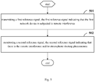
- Step 501 transmitting a first reference signal, the first reference signal indicating that the first network device is subjected to remote interference.
- the first reference signal may be called as a reference signal of a first type, or an interfered signal.
- the first reference signal may be used to trigger another network device to perform an interference backoff operation.
- Step 501 when the first network device determines that there is the remote interference, the first network device may transmit the first reference signal.
- the first network device may determine that there is the remote interference, and transmit the first reference signal.
- the uplink IoT exhibits the remote interference characteristic, it means that the uplink IoT is greater than a predetermined threshold.
- the threshold will not be particularly defined herein.
- Step 502 monitoring a second reference signal, the second reference signal indicating that there is the remote interference and/or atmospheric ducting phenomenon.
- the second reference signal may also be called as a reference signal of a second type, or a feedback reference signal.
- the second reference signal may be used to determine whether an atmospheric ducting phenomenon has disappeared.
- the first reference signal may be the same as, or different from, the second reference signal, and a forms of the first reference signal and the second reference signal will not be particularly defined herein.
- the second reference signal may be monitored in any one of the following modes.
- the second reference signal indicating that there is the remote interference and/or atmospheric ducting phenomenon, it is to accurately determine whether a factor causing the remote interference has disappeared, thereby to effectively prevent the occurrence of the ping-pong effect when handling the remote interference.
- the present disclosure further provides in some embodiments a signal transmission method executed by a first network device which serves as an aggressor site and/or a victim site.
- the first network device may be a 4G LTE base station, a 5G NR base station, or a network device in another other communication system.
- the signal transmission method includes the following steps.
- Step 601 determining whether there is remote interference, proceeding to Step 602 when there is the remote interference, and performing Step 601 continuously when there is no remote interference.
- an uplink IoT of the first network device exhibits a remote interference characteristic
- the remote interference may be determined.
- the uplink IoT exhibits the remote interference characteristic, it means that the uplink IoT is greater than a predetermined threshold.
- the threshold will not be particularly defined herein.
- Step 602 transmitting a first reference signal, the first reference signal indicating that the first network device is subjected to the remote interference.
- Step 603 monitoring a second reference signal, the second reference signal indicating that there is the remote interference and/or atmospheric ducting phenomenon, and proceeding to Step 604, 605 or 606.
- Step 604 when no second reference signal has been monitored, stopping the transmission of the first reference signal.
- Step 605 when no second reference signal has been monitored within a first time window, stopping the monitoring of the second reference signal.
- the first time window may be, but not limited to, configured by the first network device or an OAM
- Step 606 stopping the monitoring of the second reference signal in accordance with an OAM configuration.
- Step 602 may be performed continuously.
- Step 604 and Step 605 when no second reference signal has been monitored, at least one of the following may be met: a signal intensity of the monitored second reference signal is smaller than a first threshold, and the quantity of the monitored second reference signals is smaller than a second threshold.
- the signal intensity of the monitored second reference signal is greater than the first threshold
- the quantity of the monitored second reference signals is greater than the second threshold
- the first threshold and the second threshold may be set according to the practical need, and thus will not be particularly defined herein.
- first reference signal and the second reference signal in Fig.6 may be the same as that in Fig.5 , and thus will not be particularly defined herein.
- the second reference signal indicating that there is the remote interference and/or atmospheric ducting phenomenon, it is to accurately determine whether a factor causing the remote interference has disappeared, thereby to effectively prevent the occurrence of a ping-pong effect when handling the remote interference.
- the present disclosure further provides in some embodiments a signal transmission method executed by a second network device which serves as an aggressor site and/or a victim site.
- the second network device may be a 4G LTE base station, a 5G NR base station, or a network device in any other communication system.
- the signal transmission method includes the following steps.
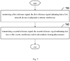
- Step 701 monitoring a first reference signal, the first reference signal indicating that a first network device is subjected to remote interference.
- the first reference signal may be called as a reference signal of a first type, or an interfered signal.
- the first reference signal may be used to trigger another network device to perform an interference backoff operation.
- the first reference signal may be monitored in any one of the following modes.
- Step 702 transmitting a second reference signal, the second reference signal indicating that there is the remote interference and/or atmospheric ducting phenomenon.
- the second reference signal may also be called as a reference signal of a second type, or a feedback reference signal.
- the second reference signal may be used to determine whether an atmospheric ducting phenomenon has disappeared.
- the first reference signal may be the same as, or different from, the second reference signal, and a forms of the first reference signal and the second reference signal will not be particularly defined herein.
- the second reference signal indicating that there is the remote interference and/or atmospheric ducting phenomenon, it is to accurately determine whether a factor causing the remote interference has disappeared, thereby to effectively prevent the occurrence of a ping-pong effect when handling the remote interference.
- the present disclosure further provides in some embodiments a signal transmission method executed by a second network device which serves as an aggressor site and/or a victim site.
- the second network device may be a 4G LTE base station, a 5G NR base station, or a network device in any other communication system.
- the signal transmission method includes the following steps.
- Step 801 determining whether a first reference signal has been monitored, the first reference signal indicating that a first network device is subjected to remote interference; when the first reference signal has been monitored, proceeding to Step 802, and when no first reference signal has been monitored, proceeding to Step 803, 804 or 805.
- the first reference signal may be called as a reference signal of a first type, or an interfered signal.
- the first reference signal may be used to trigger another network device to perform an interference backoff operation.
- the first reference signal may be monitored in any one of the following modes.
- Step 802 when the first reference signal has been monitored, transmitting a second reference signal, the second reference signal indicating that there is the remote interference and/or atmospheric ducting phenomenon.
- the second reference signal may also be called as a reference signal of a second type, or a feedback reference signal.
- the second reference signal may be used to determine whether an atmospheric ducting phenomenon has disappeared.
- the first reference signal may be the same as, or different from, the second reference signal, and a forms of the first reference signal and the second reference signal will not be particularly defined herein.
- remote interference management may be performed.
- the remote interference management may include remote interference avoidance and/or remote interference cancellation.
- Step 803 when no first reference signal has been monitored, stopping the transmission of the second reference signal, and returning to Step 801.
- remote interference management when no first reference signal has been monitored, remote interference management may be stopped.
- the remote interference management may include remote interference avoidance and/or remote interference cancellation.
- Step 804 when no first reference signal has been monitored within a second time window, stopping the monitoring of the first reference signal.
- the second time window may be, but not limited to, configured by the first network device or an OAM
- Step 805 stopping the monitoring of the first reference signal in accordance with an OAM configuration.
- Steps 803 and 804 when no first reference signal has been monitored, at least one of the following may be met: a signal intensity of the monitored first reference signal is smaller than a third threshold, and the quantity of the monitored first reference signals is smaller than a fourth threshold.
- the signal intensity of the monitored first reference signal is greater than the third threshold
- the quantity of the monitored first reference signals is greater than the fourth threshold
- the third threshold and the fourth threshold may be set according to the practical need, and thus will not be particularly defined herein.
- first reference signal and the second reference signal in Fig.8 may be the same as that in Fig.7 , and thus will not be particularly defined herein.
- the second reference signal indicating that there is the remote interference and/or atmospheric ducting phenomenon, it is to accurately determine whether a factor causing the remote interference has disappeared, thereby to effectively prevent the occurrence of a ping-pong effect when handling the remote interference.
- the present disclosure further provides in some embodiments a signal transmission method, which includes the following steps.
- Step 901 determining, by a first network device, whether there is remote interference, proceeding to Step 902 when there is the remote interference, and performing Step 901 continuously when there is no remote interference.
- the first network device may be a victim site.
- the first network device may determine that there is the remote interference.
- the uplink IoT exhibits the remote interference characteristic, it means that the uplink IoT is greater than a predetermined threshold.
- the threshold will not be particularly defined herein.
- Step 902 transmitting, by the first network device, a first reference signal, the first reference signal indicating that the first network device is subjected to the remote interference.
- Step 902 may be the same as the above-mentioned Step 501, and thus will not be particularly defined herein.
- Step 903 determining, by a second network device, whether the first reference signal has been monitored, proceeding to Step 904 when the first reference signal has been monitored, and proceeding to Step 905 when no first reference signal has been monitored.
- the second network device may be an aggressor site.
- Step 904 transmitting, by the second network device, a second reference signal when the first reference signal has been monitored, the second reference signal indicating that there is the remote interference and/or atmospheric ducting phenomenon.
- the second network device may perform remote interference management, and the remote interference management may include remote interference avoidance and/or remote interference cancellation.
- the first reference signal may be the same as, or different from, the second reference signal.
- Step 905 stopping, by the second network device, the transmission of the second reference signal when no first reference signal has been monitored.
- Step 905 when no first reference signal has been monitored, at least one of the following may be met: the signal intensity of the monitored first reference signal is smaller than the third threshold, and the quantity of the monitored first reference signals is smaller than the fourth threshold.
- Step 906 determining, by the first network device, whether the second reference signal has been monitored, proceeding to Step 907 when no second reference signal has been monitored, and returning to Step 902 when the second reference signal has been monitored.
- the first reference signal may be the same as, or different from, the second reference signal.
- Step 907 stopping, by the first network device, the transmission of the first reference signal when no second reference signal has been monitored.
- the second reference signal indicating that there is the remote interference and/or atmospheric ducting phenomenon, it is to accurately determine whether a factor causing the remote interference has disappeared, thereby to effectively prevent the occurrence of a ping-pong effect when handling the remote interference.
- Fig. 10 shows a Remote Interference Management (RIM) procedure.
- RIM Remote Interference Management
- RS specific reference signal
- UL uplink
- the atmospheric ducting phenomenon occurs, and the reception of UL data for the victim site is interfered by a downlink (DL) signal from the aggressor site.
- DL downlink
- the victim site has detected the remote interference characteristic, and starts to transmit the RS, so as to notify a potential aggressor site to perform a necessary interference backoff operation.
- the aggressor site performs the interference backoff operation.
- the aggressor site has detected the RS but fails to detect the remote interference characteristic, the aggressor site also needs to transmit the RS.
- the interference backoff operation may include at least one of: (1) reducing transmission power of the downlink signal in at least one DL OFDM symbol, (2) increasing a time-domain GP; and (3) prohibiting the transmission of a signal in a specific DL OFDM symbol.
- a condition where the base station stops the transmission of the RS may be that any RS fails to be monitored within a given time period.
- all base stations are capable of monitoring the RS from the other base station as long as the atmospheric ducting phenomenon has not disappeared, so the condition for stopping the transmission of the RS may not be triggered. Hence, all the base stations may transmit the RS continuously, so as to maintain the interference backoff operation.
- any base station is incapable of monitoring the DL signal (including the RS) from the other base station within a UL signal reception window merely when the atmospheric ducting phenomenon disappears.
- the entire RIM procedure in Fig.3 may be terminated, i.e., (1) an interference backoff procedure may be terminated by the aggressor site, and (2) both the aggressor site and the victim site may stop the transmission of the RS.
- the present disclosure further provides in some embodiments a first network device.
- a principle for the first network device to solve the problem is similar to that for the above-mentioned signal transmission method, so the implementation of the first network device may refer to that of the signal transmission method, and thus will not be particularly defined herein.
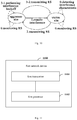
- the first network device includes a first transceiver 1101 and a first processor 1102.
- the first transceiver 1101 is configured to transmit a first reference signal, and the first reference signal indicates that the first network device is subjected to remote interference.
- the first transceiver 1101 is further configured to monitor a second reference signal, and the second reference signal indicates that there is the remote interference and/or atmospheric ducting phenomenon.
- the first transceiver 1101 is further configured to transmit the first reference signal when there is the remote interference.
- the first transceiver 1101 is further configured to determine that there is the remote interference when an uplink IoT of the first network device exhibits a remote interference characteristic, and transmit the first reference signal.
- the first transceiver 1101 is further configured to stop the transmission of the first reference signal when no second reference signal indicating that there is the remote interference and/or atmospheric ducting phenomenon has not been monitored.
- the first transceiver 1101 is further configured to monitor the second reference signal when the uplink IoT of the first network device exhibits the remote interference characteristic, or monitor the second reference signal in accordance with an OAM configuration.
- the first transceiver 1101 is further configured to stop the monitoring of the second reference signal when no second reference signal indicating that there is the remote interference and/or atmospheric ducting phenomenon has been monitored within a first time down, or stop the monitoring of the second reference signal in accordance with the OAM configuration.
- the first time window may be configured by the first network device or an OAM
- a signal intensity of the monitored second reference signal is smaller than a first threshold
- the quantity of the monitored second reference signals is smaller than a second threshold
- the first reference signal may be the same as, or different from, the second reference signal.
- the first network device in the embodiments of the present disclosure is capable of implementing the steps in the methods as shown in Figs.5-6 , which will not be particularly defined herein.
- the second reference signal indicating that there is the remote interference and/or atmospheric ducting phenomenon, it is to accurately determine whether a factor causing the remote interference has disappeared, thereby to effectively prevent the occurrence of a ping-pong effect when handling the remote interference.
- the present disclosure further provides in some embodiments a second network device.
- a principle for the second network device to solve the problem is similar to that for the above-mentioned signal transmission method, so the implementation of the second network device may refer to that of the signal transmission method, which will not be particularly defined herein.
- the second network device includes a second transceiver 1201 and a second processor 1202.
- the second transceiver 1201 is configured to monitor a first reference signal, and the first reference signal indicates that the first network device is subjected to remote interference.
- the second transceiver 1201 is further configured to transmit a second reference signal, and the second reference signal indicates that there is the remote interference and/or atmospheric ducting phenomenon.
- the first reference signal may be the same as, or different from, the second reference signal.
- the second transceiver 1201 is further configured to monitor the first reference signal when an uplink IoT of the second network device exhibits a remote interference characteristic, or monitor the first reference signal in accordance with an OAM configuration.
- the second transceiver 1201 is further configured to perform a remote interference management when the first reference signal has been monitored, and the remote interference management may include remote interference avoidance and/or remote interference cancellation.
- the second transceiver 1201 is further configured to transmit the second reference signal when the first reference signal has been monitored.
- the second transceiver 1201 is further configured to stop remote interference management when no first reference signal has been monitored, and the remote interference management may include remote interference avoidance and/or remote interference cancellation.
- the second transceiver 1201 is further configured to stop the transmission of the second reference signal when no first reference signal has been monitored.
- the second transceiver 1201 is further configured to stop the monitoring of the first reference signal when no first reference signal has been monitored within a second time window, or stop the monitoring of the first reference signal in accordance with an OAM configuration.
- the second time window may be configured by the second network device or an OAM
- the second network device in the embodiments of the present disclosure is capable of implementing the steps of the methods in Figs.7-8 , which will not be particularly defined herein.
- the second reference signal indicating that there is the remote interference and/or atmospheric ducting phenomenon, it is to accurately determine whether a factor causing the remote interference has disappeared, thereby to effectively prevent the occurrence of a ping-pong effect when handling the remote interference.
- the present disclosure further provides in some embodiments a network device.
- a principle for the network device to solve the problem is similar to that for the above-mentioned signal transmission method, so the implementation of the network device may refer to that of the signal transmission method and thus will not be particularly defined herein.
- the network device 1300 includes a processor 1301, a transceiver 1302, a memory 1303 and a bus interface.
- the processor 1301 may take charge of managing the bus architecture as well as general processings.
- the memory 1303 may store therein data for the operation of the processor 1301.
- the network device 1300 may further include a computer program stored in the memory 1303 and executed by the processor 1301.
- the computer program is executed by the processor 1301 so as to implement the steps of the above-mentioned methods.
- bus architecture may include a number of buses and bridges connected to each other, so as to connect various circuits for one or more processors 1301 and one or more memories 1303.
- the bus architecture may be used to connect any other circuits, such as a circuit for a peripheral device, a circuit for a voltage stabilizer and a power management circuit.
- the bus interface may be provided, and the transceiver 1302 may consist of a plurality of elements, i.e., a transmitter and a receiver for communication with any other devices over a transmission medium.
- the steps of the methods or algorithm described in conjunction with the contents mentioned hereinabove may be implemented through hardware, or implemented by a processor executing instructions.
- the instructions may consist of corresponding modules stored in a Random Access Memory (RAM), a flash memory, a Read Only Memory (ROM), an Electrically Programmable Read Only Memory (EPROM), an Electrically Erasable Programmable Read Only Memory (EEPROM), a register, a hard disk, a mobile hard disk, a read-only optic disk, or any other known storage medium.
- the storage medium may be coupled to the processor, so that the processor is capable of reading information from the storage medium and writing information into the storage medium.
- the storage medium may be a component of the processor.
- the processor and the storage medium may be located in an Application Specific Integrated Circuit (ASIC).
- ASIC Application Specific Integrated Circuit
- the ASIC may be located in an interface device of a core network.
- the processor and the storage medium may be located in the interface device of the core network as discrete assemblies.
- the functions described in one or more embodiments of the present disclosure may be achieved through hardware, software, firmware or a combination thereof.
- these functions may be stored in the computer-readable medium or transmitted as one or more instructions or codes on the computer-readable medium.
- the computer-readable medium may include a computer-readable storage medium and a communication medium.
- the communication medium may include any medium capable of transmitting a computer program from one place to another place.
- the storage medium may include any available medium capable of being accessed by a general-purpose or dedicated computer.
- the present disclosure may be provided as a method, a system or a computer program product, so the present disclosure may be in the form of full hardware embodiments, full software embodiments, or combinations thereof.
- the present disclosure may be in the form of a computer program product implemented on one or more computer-readable storage mediums (including but not limited to disk memory, compact disc-read only memory (Compact Disc-Read Only Memory, CD-ROM) and optical memory) including computer-readable program codes.
- These computer program instructions may also be stored in a computer readable storage that may guide the computer or the other programmable data process devices to function in a certain way, so that the instructions stored in the computer readable storage may create a product including an instruction unit which achieves the functions assigned in one or more flows in the flow chart and/or one or more blocks in the block diagram.
- These computer program instructions may also be loaded in the computer or the other programmable data process devices, so that a series of operation steps are executed on the computer or the other programmable devices to create processes achieved by the computer. Therefore, the instructions executed in the computer or the other programmable devices provide the steps for achieving the function assigned in one or more flows in the flow chart and/or one or more blocks in the block diagram.
Landscapes
- Engineering & Computer Science (AREA)
- Signal Processing (AREA)
- Computer Networks & Wireless Communication (AREA)
- Quality & Reliability (AREA)
- Physics & Mathematics (AREA)
- Electromagnetism (AREA)
- Mobile Radio Communication Systems (AREA)
Abstract
Description
- The present application claims a priority of the Chinese patent application No.
201810886392.4 filed on August 6, 2018 - The present disclosure relates to the field of communication technology, in particular to a signal transmission method and a signal transmission device.
- Such a phenomenon as atmospheric ducting phenomenon easily occurs in an inland area at the end of spring and the beginning of summer or at the end of summer and the beginning of autumn, or in a coastal area in winter. As shown in
Fig. 1 , when the atmospheric ducting phenomenon occurs, there exists in the troposphere a thermal inversion layer or a layer where the amount of water vapor dramatically decreases along with an increase in height, which is called as atmospheric ducting phenomenon layer. A majority of radio radiation is restricted in the waveguide layer for super-refraction propagation. Due to the over-the-horizon propagation, a radio signal may be transmitted over a very large distance with relatively small path loss. - For a cellular radio communication system (e.g., a fourth-Generation (4G) Long Term Evolution (LTE) system, or a fifth-Generation (5G) New Radio (NR) system), when the atmospheric ducting phenomenon occurs, a strong interference may be caused by a downlink (DL) signal for a remote base station on the reception of uplink (UL) data for a local base station.
- As shown in
Fig.2 , due to the existence of the atmospheric ducting phenomenon layer, after the propagation over a very long distance (e.g., tens or hundreds of kilometers), a DL signal transmitted by a remote aggressor site (interference site or interfering site) still has relative high energy. When the signal enters a UL signal reception window of a local victim site (interfered site), the strong interference may be caused on the reception of the UL data for the local base station. - It is found in a current Time Division Long Term Evolution (TD-LTE) network that, the uplink data for the TD-LTE in such provinces as Jiangsu, Anhui, Hainan and He'nan is widely interfered, an uplink Interference over Thermal (IoT) is increased by up to 25dB, and such Key Performance Indicator (KPI) as Radio Resource Control (RRC) connection establishment success rate is deteriorated seriously. Victim cells are mainly at a frequency band F in rural areas within a time period principally from 0:00 to 8:00, and hundreds to tens of thousands of base stations are affected.
- As shown in
Fig.3 , in the networking of a Time Division Duplexing (TDD) system, in order to prevent uplink and downlink interference between cells, usually a same uplink/downlink configuration is selected. In addition, a Guard Period (GP) is provided between downlink transmission and uplink transmission, and it usually includes N Orthogonal Frequency Division Multiplexing (OFDM) symbols (e.g., N<14). A GP length is selected in such a manner as to ensure that the downlink transmission for the base station within a certain range (e.g., tens of kilometers) does not interfere with the uplink reception for a current base station. - Usually, considering the loss of an electromagnetic wave propagated in the space, the current base station fails to experience the interference caused by the downlink transmission for the base station at a distance of tens or hundreds of kilometers.
- However, due to such factors as atmospheric refraction and a propagation environment, the downlink transmission for a remote base station at a distance of tens or hundreds of kilometers may interfere with the uplink reception for the current base station, and this is called as remote interference. In the remote interference, an interference range is up to tens or hundreds of kilometers (e.g., 300km), a propagation delay is 1 ms which is greater than the GP for uplink/downlink switching, and an interference source is a downlink resource before the GP.
- Hence, there is an urgent need to provide a scheme for preventing the remote interference.
- An object of the present disclosure is to provide a signal transmission method and a signal transmission device, so as to prevent the remote interference.
- In a first aspect, the present disclosure provides in some embodiments a signal transmission method applied for a first network device, including: transmitting a first reference signal, the first reference signal indicating that the first network device is subjected to remote interference; and monitoring a second reference signal, the second reference signal indicating that there is the remote interference and/or atmospheric ducting phenomenon.
- In a second aspect, the present disclosure provides in some embodiments a signal transmission method applied for a second network device, including: monitoring a first reference signal, the first reference signal indicating that a first network device is subjected to remote interference; and transmitting a second reference signal, the second reference signal indicating that there is the remote interference and/or atmospheric ducting phenomenon.
- In a third aspect, the present disclosure provides in some embodiments a first network device, including a first transceiver and a first processor. The first transceiver is configured to transmit a first reference signal, and the first reference signal indicates that the first network device is subjected to remote interference. The first transceiver is further configured to monitor a second reference signal, and the second reference signal indicates that there is the remote interference and/or atmospheric ducting phenomenon.
- In a fourth aspect, the present disclosure provides in some embodiments a second network device, including a second transceiver and a second processor. The second transceiver is configured to monitor a first reference signal, and the first reference signal indicates that the first network device is subjected to remote interference. The second transceiver is further configured to transmit a second reference signal, and the second reference signal indicates that there is the remote interference and/or atmospheric ducting phenomenon.
- In a fifth aspect, the present disclosure provides in some embodiments a network device, including a processor, a memory, and a computer program stored in the memory and executed by the processor. The computer program is executed by the processor so as to implement the steps of the above-mentioned signal transmission method applied for the first network device, or implement the steps of the above-mentioned signal transmission method applied for the second network device.
- In a sixth aspect, the present disclosure provides in some embodiments a computer-readable storage medium storing therein a computer program. The computer program is executed by a processor so as to implement the steps of the above-mentioned signal transmission method applied for the first network device, or implement the steps of the above-mentioned signal transmission method applied for the second network device.
- According to the embodiments of the present disclosure, through the second reference signal indicating that there is the remote interference and/or atmospheric ducting phenomenon, it is able to accurately determine whether a factor causing the remote interference has disappeared, thereby to effectively prevent the occurrence of a ping-pong effect when handling the remote interference.
- Through reading the detailed description hereinafter, the other advantages and benefits will be apparent to a person skilled in the art. The drawings are merely used to show the preferred embodiments, but shall not be construed as limiting the present disclosure. In addition, in the drawings, same reference symbols represent same members. In these drawings,
-
Fig.1 is a schematic view showing an atmospheric ducting phenomenon; -
Fig.2 is a schematic view showing interference caused by a remote base station; -
Fig.3 is a schematic view showing remote interference; -
Fig.4 is another schematic view showing the remote interference; -
Fig.5 is a flow chart of a signal transmission method according to one embodiment of the present disclosure; -
Fig.6 is another flow chart of the signal transmission method according to one embodiment of the present disclosure; -
Fig.7 is yet another flow chart of the signal transmission method according to one embodiment of the present disclosure; -
Fig.8 is still yet another flow chart of the signal transmission method according to one embodiment of the present disclosure; -
Fig.9 is a schematic view showing signal transmission according to one embodiment of the present disclosure; -
Fig. 10 is a schematic view showing an NR-RIM scheme according to one embodiment of the present disclosure; -
Fig.1 1 is a schematic view showing a first network device according to one embodiment of the present disclosure; -
Fig. 12 is a schematic view showing a second network device according to one embodiment of the present disclosure; and -
Fig. 13 is a schematic view showing a network device according to one embodiment of the present disclosure. - In order to make the objects, the technical solutions and the advantages of the present disclosure more apparent, the present disclosure will be described hereinafter in a clear and complete manner in conjunction with the drawings and embodiments. Obviously, the following embodiments merely relate to a part of, rather than all of, the embodiments of the present disclosure, and based on these embodiments, a person skilled in the art may, without any creative effort, obtain the other embodiments, which also fall within the scope of the present disclosure.
- Such words as "include" or "including" or any other variations involved in the present disclosure intend to provide non-exclusive coverage, so that a procedure, method, system, product or device including a series of steps or units may also include any other elements not listed herein, or may include any inherent steps or units of the procedure, method, system, product or device. In addition, the expression "and/or" is merely used to describe the relationship between objects, and it may include three situations. For example, "A and/or B" may represent that, there is only A, there are both A and B, and there is only B.
- Such expressions as "illustrative" and "for example" are merely used to show examples or explanations. Any illustrative embodiment or scheme in the present disclosure shall not be construed as being superior over the other embodiment or scheme. Definitely, these words intend to exhibit relevant concepts in a concrete manner.
- The technology described in the context shall not be limited to a Long Term Evolution (LTE)/LTE-Advanced (LTE-A) system, and it may also be applied to various wireless communication systems, e.g., Code Division Multiple Access (CDMA), Time Division Multiple Access (TDMA), Frequency Division Multiple Access (FDMA), Orthogonal Frequency Division Multiple Access (OFDMA), Single-Carrier Frequency-Division Multiple Access (SC-FDMA), or any other system, e.g., 5G NR.
- The terms "system" and "network" may be replaced with each other. The CDMA system may be used to implement such radio technologies as CDMA2000 and Universal Terrestrial Radio Access (UTRA). The UTRA may include Wideband Code Division Multiple Access (WCDMA) and the other CDMA variants. The TDMA system may be used to implement such a radio technology as Global System for Mobile Communication (GSM). The OFDMA system may be used to implement such radio technologies as Ultra Mobile Broadband (UMB), Evolved-UTRA (E-UTRA), IEEE 802.11 (Wireless Fidelity (Wi-Fi)), IEEE 802.16 (WiMAX), IEEE 802.20, and Flash-OFDM. The UTRA and the E-UTRA are parts of a Universal Mobile Telecommunications System (UMTS). The LTE and a more advanced LTE (e.g., LTE-A) are new UMTS versions using the E-UTRA. The UTRA, E-UTRA, UMTS, LTE, LTE-A and GSM have been described in literatures from the 3rd-Generation Partnership Project (3GPP). The technology described in the context may be applied to the above-mentioned systems and radio technologies, or applied to the other systems and radio technologies.
-
Fig. 4 shows a basic remote interference management procedure which includes the following steps. - Step 401: transmitting, by a victim site, an interfered signal when remote interference has been detected.
- Step 402: upon the receipt of the corresponding interfered signal, performing, by an aggressor site, an interference backoff operation.
- The interference backoff operation refers to an operation where a downlink transmission resource before a GP is sacrificed.
- Step 403: stopping, by the victim site, the transmission of the interfered signal when the remote interference fails to be detected.
- Step 404: restoring an original transmission mode when the aggressor site fails to receive the corresponding interfered signal.
- However, in the above remote interference management procedure, subsequent to Step 404, when the factors that cause the remote interference, e.g., the atmospheric refraction, do not disappear, the victim site may be interfered continuously, and thereby it is necessary to perform Steps 401 to 404 again. At this time, a ping-pong effect may occur when handling the remote interference.
- As shown in
Fig.5 , the present disclosure provides in some embodiments a signal transmission method executed by a first network device which serves as an aggressor site and/or a victim site. The first network device may be a 4G LTE base station, a 5G NR base station, or a network device in any other communication system. The signal transmission method includes the following steps. - Step 501: transmitting a first reference signal, the first reference signal indicating that the first network device is subjected to remote interference.
- The first reference signal may be called as a reference signal of a first type, or an interfered signal. In a possible embodiment of the present disclosure, the first reference signal may be used to trigger another network device to perform an interference backoff operation.
- In a possible embodiment of the present disclosure, in
Step 501, when the first network device determines that there is the remote interference, the first network device may transmit the first reference signal. To be specific, when an uplink IoT of the first network device exhibits a remote interference characteristic, the first network device may determine that there is the remote interference, and transmit the first reference signal. When the uplink IoT exhibits the remote interference characteristic, it means that the uplink IoT is greater than a predetermined threshold. Of course, it should be appreciated that, the threshold will not be particularly defined herein. - Step 502: monitoring a second reference signal, the second reference signal indicating that there is the remote interference and/or atmospheric ducting phenomenon.
- The second reference signal may also be called as a reference signal of a second type, or a feedback reference signal. In a possible embodiment of the present disclosure, the second reference signal may be used to determine whether an atmospheric ducting phenomenon has disappeared.
- It should be appreciated that, in the embodiments of the present disclosure, the first reference signal may be the same as, or different from, the second reference signal, and a forms of the first reference signal and the second reference signal will not be particularly defined herein.
- In a possible embodiment of the present disclosure, in
Step 502, the second reference signal may be monitored in any one of the following modes. - (1) When the uplink IoT of the first network device exhibits the remote interference characteristic, the second reference signal may be monitored.
When the uplink IoT exhibits the remote interference characteristic, it means that the uplink IoT is greater than the predetermined threshold. Of course, it should be appreciated that, the threshold will not be particularly defined herein. - (2) The second reference signal may be monitored in accordance with an Operation, Administration and Maintenance (OAM) configuration.
- According to the embodiments of the present disclosure, through the second reference signal indicating that there is the remote interference and/or atmospheric ducting phenomenon, it is to accurately determine whether a factor causing the remote interference has disappeared, thereby to effectively prevent the occurrence of the ping-pong effect when handling the remote interference.
- As shown in
Fig.6 , the present disclosure further provides in some embodiments a signal transmission method executed by a first network device which serves as an aggressor site and/or a victim site. The first network device may be a 4G LTE base station, a 5G NR base station, or a network device in another other communication system. The signal transmission method includes the following steps. - Step 601: determining whether there is remote interference, proceeding to Step 602 when there is the remote interference, and performing
Step 601 continuously when there is no remote interference. - For example, when an uplink IoT of the first network device exhibits a remote interference characteristic, there is the remote interference may be determined. When the uplink IoT exhibits the remote interference characteristic, it means that the uplink IoT is greater than a predetermined threshold. Of course, it should be appreciated that, the threshold will not be particularly defined herein.
- Step 602: transmitting a first reference signal, the first reference signal indicating that the first network device is subjected to the remote interference.
- Step 603: monitoring a second reference signal, the second reference signal indicating that there is the remote interference and/or atmospheric ducting phenomenon, and proceeding to Step 604, 605 or 606.
- Step 604: when no second reference signal has been monitored, stopping the transmission of the first reference signal.
- Step 605: when no second reference signal has been monitored within a first time window, stopping the monitoring of the second reference signal.
- The first time window may be, but not limited to, configured by the first network device or an OAM
- Step 606: stopping the monitoring of the second reference signal in accordance with an OAM configuration.
- It should be appreciated that, when the second reference signal has been monitored,
Step 602 may be performed continuously. - In the embodiments of the present disclosure, in
Step 604 andStep 605, when no second reference signal has been monitored, at least one of the following may be met: a signal intensity of the monitored second reference signal is smaller than a first threshold, and the quantity of the monitored second reference signals is smaller than a second threshold. - In the embodiments of the present disclosure, when the second reference signal has been monitored, at least one of the following may be met: the signal intensity of the monitored second reference signal is greater than the first threshold, and the quantity of the monitored second reference signals is greater than the second threshold.
- It should be appreciated that, the first threshold and the second threshold may be set according to the practical need, and thus will not be particularly defined herein.
- It should be appreciated that, the description about the first reference signal and the second reference signal in
Fig.6 may be the same as that inFig.5 , and thus will not be particularly defined herein. - According to the embodiments of the present disclosure, through the second reference signal indicating that there is the remote interference and/or atmospheric ducting phenomenon, it is to accurately determine whether a factor causing the remote interference has disappeared, thereby to effectively prevent the occurrence of a ping-pong effect when handling the remote interference.
- As shown in
Fig.7 , the present disclosure further provides in some embodiments a signal transmission method executed by a second network device which serves as an aggressor site and/or a victim site. The second network device may be a 4G LTE base station, a 5G NR base station, or a network device in any other communication system. The signal transmission method includes the following steps. - Step 701: monitoring a first reference signal, the first reference signal indicating that a first network device is subjected to remote interference.
- The first reference signal may be called as a reference signal of a first type, or an interfered signal. In a possible embodiment of the present disclosure, the first reference signal may be used to trigger another network device to perform an interference backoff operation.
- In a possible embodiment of the present disclosure, in
Step 701, the first reference signal may be monitored in any one of the following modes. - (1) When an uplink IoT of the second network device exhibits a remote interference characteristic, the first reference signal may be monitored.
When the uplink IoT exhibits the remote interference characteristic, it means that the uplink IoT is greater than a predetermined threshold. Of course, it should be appreciated that, the threshold will not be particularly defined herein. - (2) The first reference signal may be monitored in accordance with an OAM configuration.
- Step 702: transmitting a second reference signal, the second reference signal indicating that there is the remote interference and/or atmospheric ducting phenomenon.
- The second reference signal may also be called as a reference signal of a second type, or a feedback reference signal. In a possible embodiment of the present disclosure, the second reference signal may be used to determine whether an atmospheric ducting phenomenon has disappeared.
- It should be appreciated that, in the embodiments of the present disclosure, the first reference signal may be the same as, or different from, the second reference signal, and a forms of the first reference signal and the second reference signal will not be particularly defined herein.
- According to the embodiments of the present disclosure, through the second reference signal indicating that there is the remote interference and/or atmospheric ducting phenomenon, it is to accurately determine whether a factor causing the remote interference has disappeared, thereby to effectively prevent the occurrence of a ping-pong effect when handling the remote interference.
- As shown in
Fig.8 , the present disclosure further provides in some embodiments a signal transmission method executed by a second network device which serves as an aggressor site and/or a victim site. The second network device may be a 4G LTE base station, a 5G NR base station, or a network device in any other communication system. The signal transmission method includes the following steps. - Step 801: determining whether a first reference signal has been monitored, the first reference signal indicating that a first network device is subjected to remote interference; when the first reference signal has been monitored, proceeding to Step 802, and when no first reference signal has been monitored, proceeding to Step 803, 804 or 805.
- The first reference signal may be called as a reference signal of a first type, or an interfered signal. In a possible embodiment of the present disclosure, the first reference signal may be used to trigger another network device to perform an interference backoff operation.
- In a possible embodiment of the present disclosure, in
Step 801, the first reference signal may be monitored in any one of the following modes. - (1) The first reference signal may be monitored when an uplink IoT of the second network device exhibits a remote interference characteristic.
When the uplink IoT exhibits the remote interference characteristic, it means that the uplink IoT is greater than a predetermined threshold. Of course, it should be appreciated that, the threshold will not be particularly defined herein. - (2) The first reference signal may be monitored in accordance with an OAM configuration.
- Step 802: when the first reference signal has been monitored, transmitting a second reference signal, the second reference signal indicating that there is the remote interference and/or atmospheric ducting phenomenon.
- The second reference signal may also be called as a reference signal of a second type, or a feedback reference signal. In a possible embodiment of the present disclosure, the second reference signal may be used to determine whether an atmospheric ducting phenomenon has disappeared.
- It should be appreciated that, in the embodiments of the present disclosure, the first reference signal may be the same as, or different from, the second reference signal, and a forms of the first reference signal and the second reference signal will not be particularly defined herein.
- When the first reference signal has been monitored, remote interference management may be performed. The remote interference management may include remote interference avoidance and/or remote interference cancellation.
- Step 803: when no first reference signal has been monitored, stopping the transmission of the second reference signal, and returning to
Step 801. - In the embodiments of the present disclosure, when no first reference signal has been monitored, remote interference management may be stopped. The remote interference management may include remote interference avoidance and/or remote interference cancellation.
- Step 804: when no first reference signal has been monitored within a second time window, stopping the monitoring of the first reference signal.
- The second time window may be, but not limited to, configured by the first network device or an OAM
- Step 805: stopping the monitoring of the first reference signal in accordance with an OAM configuration.
- In the embodiments of the present disclosure, in
Steps - Correspondingly, when the first reference signal has been monitored, at least one of the following may be met: the signal intensity of the monitored first reference signal is greater than the third threshold, and the quantity of the monitored first reference signals is greater than the fourth threshold.
- It should be appreciated that, the third threshold and the fourth threshold may be set according to the practical need, and thus will not be particularly defined herein.
- It should be appreciated that, the description about the first reference signal and the second reference signal in
Fig.8 may be the same as that inFig.7 , and thus will not be particularly defined herein. - According to the embodiments of the present disclosure, through the second reference signal indicating that there is the remote interference and/or atmospheric ducting phenomenon, it is to accurately determine whether a factor causing the remote interference has disappeared, thereby to effectively prevent the occurrence of a ping-pong effect when handling the remote interference.
- As shown in
Fig. 9 , the present disclosure further provides in some embodiments a signal transmission method, which includes the following steps. - Step 901: determining, by a first network device, whether there is remote interference, proceeding to Step 902 when there is the remote interference, and performing
Step 901 continuously when there is no remote interference. - The first network device may be a victim site.
- For example, when an uplink IoT of the first network device exhibits a remote interference characteristic, the first network device may determine that there is the remote interference. When the uplink IoT exhibits the remote interference characteristic, it means that the uplink IoT is greater than a predetermined threshold. Of course, it should be appreciated that, the threshold will not be particularly defined herein.
- Step 902: transmitting, by the first network device, a first reference signal, the first reference signal indicating that the first network device is subjected to the remote interference.
- In the embodiments of the present disclosure,
Step 902 may be the same as the above-mentionedStep 501, and thus will not be particularly defined herein. - Step 903: determining, by a second network device, whether the first reference signal has been monitored, proceeding to Step 904 when the first reference signal has been monitored, and proceeding to Step 905 when no first reference signal has been monitored.
- The second network device may be an aggressor site.
- Step 904: transmitting, by the second network device, a second reference signal when the first reference signal has been monitored, the second reference signal indicating that there is the remote interference and/or atmospheric ducting phenomenon.
- In the embodiments of the present disclosure, when the first reference signal has been monitored, at least one of the following may be met: a signal intensity of the monitored first reference signal is greater than a third threshold, and the quantity of the monitored first reference signals is greater than a fourth threshold. When the first reference signal has been monitored, the second network device may perform remote interference management, and the remote interference management may include remote interference avoidance and/or remote interference cancellation.
- In the embodiments of the present disclosure, the first reference signal may be the same as, or different from, the second reference signal.
- Step 905: stopping, by the second network device, the transmission of the second reference signal when no first reference signal has been monitored.
- In the embodiments of the present disclosure, in
Step 905, when no first reference signal has been monitored, at least one of the following may be met: the signal intensity of the monitored first reference signal is smaller than the third threshold, and the quantity of the monitored first reference signals is smaller than the fourth threshold. - Step 906: determining, by the first network device, whether the second reference signal has been monitored, proceeding to Step 907 when no second reference signal has been monitored, and returning to Step 902 when the second reference signal has been monitored.
- In the embodiments of the present disclosure, the first reference signal may be the same as, or different from, the second reference signal.
- Step 907: stopping, by the first network device, the transmission of the first reference signal when no second reference signal has been monitored.
- According to the embodiments of the present disclosure, through the second reference signal indicating that there is the remote interference and/or atmospheric ducting phenomenon, it is to accurately determine whether a factor causing the remote interference has disappeared, thereby to effectively prevent the occurrence of a ping-pong effect when handling the remote interference.
-
Fig. 10 shows a Remote Interference Management (RIM) procedure. A basic procedure may be described as follows. - At a time point T0, all base stations monitor a specific reference signal (RS for short), and a potential victim site (e.g., a base station where there is an uplink (UL) service) needs to detect an interference characteristic.
- At a time point T1, the atmospheric ducting phenomenon occurs, and the reception of UL data for the victim site is interfered by a downlink (DL) signal from the aggressor site.
- At a time point T2, the victim site has detected the remote interference characteristic, and starts to transmit the RS, so as to notify a potential aggressor site to perform a necessary interference backoff operation.
- At a time point T3, after the aggressor site has detected the RS, the aggressor site performs the interference backoff operation. When the aggressor site has detected the RS but fails to detect the remote interference characteristic, the aggressor site also needs to transmit the RS.
- The interference backoff operation may include at least one of: (1) reducing transmission power of the downlink signal in at least one DL OFDM symbol, (2) increasing a time-domain GP; and (3) prohibiting the transmission of a signal in a specific DL OFDM symbol.
- Obviously, after the aggressor site has performed the interference backoff operation, it is able to obviously relieve the interference on the UL data for the remote victim site.
- It should be appreciated that, a condition where the base station stops the transmission of the RS may be that any RS fails to be monitored within a given time period.
- After T3, all base stations are capable of monitoring the RS from the other base station as long as the atmospheric ducting phenomenon has not disappeared, so the condition for stopping the transmission of the RS may not be triggered. Hence, all the base stations may transmit the RS continuously, so as to maintain the interference backoff operation.
- Any base station is incapable of monitoring the DL signal (including the RS) from the other base station within a UL signal reception window merely when the atmospheric ducting phenomenon disappears. At this time, the entire RIM procedure in
Fig.3 may be terminated, i.e., (1) an interference backoff procedure may be terminated by the aggressor site, and (2) both the aggressor site and the victim site may stop the transmission of the RS. - In order to prevent the remote interference, the present disclosure further provides in some embodiments a first network device. A principle for the first network device to solve the problem is similar to that for the above-mentioned signal transmission method, so the implementation of the first network device may refer to that of the signal transmission method, and thus will not be particularly defined herein. As shown in
Fig.11 , the first network device includes afirst transceiver 1101 and afirst processor 1102. Thefirst transceiver 1101 is configured to transmit a first reference signal, and the first reference signal indicates that the first network device is subjected to remote interference. Thefirst transceiver 1101 is further configured to monitor a second reference signal, and the second reference signal indicates that there is the remote interference and/or atmospheric ducting phenomenon. - In a possible embodiment of the present disclosure, the
first transceiver 1101 is further configured to transmit the first reference signal when there is the remote interference. - In a possible embodiment of the present disclosure, the
first transceiver 1101 is further configured to determine that there is the remote interference when an uplink IoT of the first network device exhibits a remote interference characteristic, and transmit the first reference signal. - In a possible embodiment of the present disclosure, the
first transceiver 1101 is further configured to stop the transmission of the first reference signal when no second reference signal indicating that there is the remote interference and/or atmospheric ducting phenomenon has not been monitored. - In a possible embodiment of the present disclosure, the
first transceiver 1101 is further configured to monitor the second reference signal when the uplink IoT of the first network device exhibits the remote interference characteristic, or monitor the second reference signal in accordance with an OAM configuration. - In a possible embodiment of the present disclosure, the
first transceiver 1101 is further configured to stop the monitoring of the second reference signal when no second reference signal indicating that there is the remote interference and/or atmospheric ducting phenomenon has been monitored within a first time down, or stop the monitoring of the second reference signal in accordance with the OAM configuration. - In a possible embodiment of the present disclosure, the first time window may be configured by the first network device or an OAM
- In the embodiments of the present disclosure, when no second reference signal has been monitored, at least one of the following may be met: a signal intensity of the monitored second reference signal is smaller than a first threshold, and the quantity of the monitored second reference signals is smaller than a second threshold.
- In the embodiments of the present disclosure, the first reference signal may be the same as, or different from, the second reference signal.
- The first network device in the embodiments of the present disclosure is capable of implementing the steps in the methods as shown in
Figs.5-6 , which will not be particularly defined herein. - According to the embodiments of the present disclosure, through the second reference signal indicating that there is the remote interference and/or atmospheric ducting phenomenon, it is to accurately determine whether a factor causing the remote interference has disappeared, thereby to effectively prevent the occurrence of a ping-pong effect when handling the remote interference.
- In order to prevent the remote interference, the present disclosure further provides in some embodiments a second network device. A principle for the second network device to solve the problem is similar to that for the above-mentioned signal transmission method, so the implementation of the second network device may refer to that of the signal transmission method, which will not be particularly defined herein.
- As shown in
Fig. 12 , the second network device includes asecond transceiver 1201 and asecond processor 1202. Thesecond transceiver 1201 is configured to monitor a first reference signal, and the first reference signal indicates that the first network device is subjected to remote interference. Thesecond transceiver 1201 is further configured to transmit a second reference signal, and the second reference signal indicates that there is the remote interference and/or atmospheric ducting phenomenon. - In the embodiments of the present disclosure, the first reference signal may be the same as, or different from, the second reference signal.
- In a possible embodiment of the present disclosure, the
second transceiver 1201 is further configured to monitor the first reference signal when an uplink IoT of the second network device exhibits a remote interference characteristic, or monitor the first reference signal in accordance with an OAM configuration. - In a possible embodiment of the present disclosure, the
second transceiver 1201 is further configured to perform a remote interference management when the first reference signal has been monitored, and the remote interference management may include remote interference avoidance and/or remote interference cancellation. - In a possible embodiment of the present disclosure, the
second transceiver 1201 is further configured to transmit the second reference signal when the first reference signal has been monitored. - In a possible embodiment of the present disclosure, the
second transceiver 1201 is further configured to stop remote interference management when no first reference signal has been monitored, and the remote interference management may include remote interference avoidance and/or remote interference cancellation. - In a possible embodiment of the present disclosure, the
second transceiver 1201 is further configured to stop the transmission of the second reference signal when no first reference signal has been monitored. - In a possible embodiment of the present disclosure, the
second transceiver 1201 is further configured to stop the monitoring of the first reference signal when no first reference signal has been monitored within a second time window, or stop the monitoring of the first reference signal in accordance with an OAM configuration. - In a possible embodiment of the present disclosure, the second time window may be configured by the second network device or an OAM
- The second network device in the embodiments of the present disclosure is capable of implementing the steps of the methods in
Figs.7-8 , which will not be particularly defined herein. - According to the embodiments of the present disclosure, through the second reference signal indicating that there is the remote interference and/or atmospheric ducting phenomenon, it is to accurately determine whether a factor causing the remote interference has disappeared, thereby to effectively prevent the occurrence of a ping-pong effect when handling the remote interference.
- In order to prevent the remote interference, the present disclosure further provides in some embodiments a network device. A principle for the network device to solve the problem is similar to that for the above-mentioned signal transmission method, so the implementation of the network device may refer to that of the signal transmission method and thus will not be particularly defined herein.
- As shown in
Fig. 13 , thenetwork device 1300 includes aprocessor 1301, atransceiver 1302, amemory 1303 and a bus interface. - The
processor 1301 may take charge of managing the bus architecture as well as general processings. Thememory 1303 may store therein data for the operation of theprocessor 1301. - In the embodiments of the present disclosure, the
network device 1300 may further include a computer program stored in thememory 1303 and executed by theprocessor 1301. The computer program is executed by theprocessor 1301 so as to implement the steps of the above-mentioned methods. - In
Fig. 13 , bus architecture may include a number of buses and bridges connected to each other, so as to connect various circuits for one ormore processors 1301 and one ormore memories 1303. In addition, as is known in the art, the bus architecture may be used to connect any other circuits, such as a circuit for a peripheral device, a circuit for a voltage stabilizer and a power management circuit. The bus interface may be provided, and thetransceiver 1302 may consist of a plurality of elements, i.e., a transmitter and a receiver for communication with any other devices over a transmission medium. - The steps of the methods or algorithm described in conjunction with the contents mentioned hereinabove may be implemented through hardware, or implemented by a processor executing instructions. The instructions may consist of corresponding modules stored in a Random Access Memory (RAM), a flash memory, a Read Only Memory (ROM), an Electrically Programmable Read Only Memory (EPROM), an Electrically Erasable Programmable Read Only Memory (EEPROM), a register, a hard disk, a mobile hard disk, a read-only optic disk, or any other known storage medium. Illustratively, the storage medium may be coupled to the processor, so that the processor is capable of reading information from the storage medium and writing information into the storage medium. Of course, the storage medium may be a component of the processor. The processor and the storage medium may be located in an Application Specific Integrated Circuit (ASIC). In addition, the ASIC may be located in an interface device of a core network. Of course, the processor and the storage medium may be located in the interface device of the core network as discrete assemblies.
- It should be appreciated that, the functions described in one or more embodiments of the present disclosure may be achieved through hardware, software, firmware or a combination thereof. When the functions are achieved through software, these functions may be stored in the computer-readable medium or transmitted as one or more instructions or codes on the computer-readable medium. The computer-readable medium may include a computer-readable storage medium and a communication medium. The communication medium may include any medium capable of transmitting a computer program from one place to another place. The storage medium may include any available medium capable of being accessed by a general-purpose or dedicated computer.
- The objects, the technical solutions and the beneficial effects of the present disclosure have been described hereinabove in details. It should be appreciated that, the above description may be for illustrative purposes only, but shall not be used to limit the scope of the present disclosure. Any modifications, equivalents or improvements shall also fall within the scope of the present disclosure.
- It should be appreciated that, the present disclosure may be provided as a method, a system or a computer program product, so the present disclosure may be in the form of full hardware embodiments, full software embodiments, or combinations thereof. In addition, the present disclosure may be in the form of a computer program product implemented on one or more computer-readable storage mediums (including but not limited to disk memory, compact disc-read only memory (Compact Disc-Read Only Memory, CD-ROM) and optical memory) including computer-readable program codes.
- The present disclosure has been described with reference to the flow charts and/or block diagrams of the method, device (system) and computer program product according to the embodiments of the present disclosure. It should be understood that computer program instructions may be used to implement each of the work flows and/or blocks in the flow charts and/or the block diagrams, and the combination of the work flows and/or blocks in the flow charts and/or the block diagrams. These computer program instructions may be provided to a processor of a common computer, a dedicated computer, an embedded processor or any other programmable data processing devices to create a machine, so that instructions capable of being executed by the processor of the computer or the other programmable data processing devices may create a device to achieve the functions assigned in one or more work flows in the flow chart and/or one or more blocks in the block diagram.
- These computer program instructions may also be stored in a computer readable storage that may guide the computer or the other programmable data process devices to function in a certain way, so that the instructions stored in the computer readable storage may create a product including an instruction unit which achieves the functions assigned in one or more flows in the flow chart and/or one or more blocks in the block diagram.
- These computer program instructions may also be loaded in the computer or the other programmable data process devices, so that a series of operation steps are executed on the computer or the other programmable devices to create processes achieved by the computer. Therefore, the instructions executed in the computer or the other programmable devices provide the steps for achieving the function assigned in one or more flows in the flow chart and/or one or more blocks in the block diagram.
- The above embodiments are for illustrative purposes only, but the present disclosure is not limited thereto. Obviously, a person skilled in the art may make further modifications and improvements without departing from the spirit of the present disclosure, and these modifications and improvements shall also fall within the scope of the present disclosure.
Claims (23)
- A signal transmission method applied for a first network device, comprising:transmitting a first reference signal, the first reference signal indicating that the first network device is subjected to remote interference; andmonitoring a second reference signal, the second reference signal indicating that there is the remote interference and/or atmospheric ducting phenomenon.
- The signal transmission method according to claim 1, wherein the transmitting the first reference signal comprises transmitting the first reference signal when there is the remote interference.
- The signal transmission method according to claim 2, wherein the transmitting the first reference signal when there is the remote interference comprises determining that there is the remote interference when an uplink Interference over Thermal (IoT) of the first network device exhibits a remote interference characteristic, and transmitting the first reference signal.
- The signal transmission method according to claim 1, further comprising stopping the transmission of the first reference signal when no second reference signal has been monitored.
- The signal transmission method according to any one of claims 1 to 4, wherein the monitoring the second reference signal comprises:monitoring the second reference signal when the uplink IoT of the first network device exhibits the remote interference characteristic; ormonitoring the second reference signal in accordance with an Operation, Administration and Maintenance (OAM) configuration.
- The signal transmission method according to claim 1, further comprising:stopping the monitoring of the second reference signal when no second reference signal has been monitored within a first time window; orstopping the monitoring of the second reference signal in accordance with an OAM configuration.
- The signal transmission method according to claim 6, wherein the first time window is configured by the first network device or an OAM
- The signal transmission method according to claim 6, wherein when no second reference signal has been monitored, at least one of the following is met: a signal intensity of the monitored second reference signal is smaller than a first threshold, and the quantity of the monitored second reference signals is smaller than a second threshold.
- The signal transmission method according to any one of claims 1 to 8, wherein the first reference signal is the same as, or different from, the second reference signal.
- A signal transmission method applied for a second network device, comprising:monitoring a first reference signal, the first reference signal indicating that a first network device is subjected to remote interference; andtransmitting a second reference signal, the second reference signal indicating that there is the remote interference and/or atmospheric ducting phenomenon.
- The signal transmission method according to claim 10, wherein the monitoring the first reference signal comprises:monitoring the first reference signal when an uplink IoT of the second network device exhibits a remote interference characteristic; ormonitoring the first reference signal in accordance with an OAM configuration.
- The signal transmission method according to claim 10, further comprising performing remote interference management when the first reference signal has been monitored, wherein the remote interference management comprises remote interference avoidance and/or remote interference cancellation.
- The signal transmission method according to claim 10, further comprising transmitting the second reference signal when the first reference signal has been monitored.
- The signal transmission method according to claim 10, further comprising stopping remote interference management when no first reference signal has been monitored, wherein the remote interference management comprises remote interference avoidance and/or remote interference cancellation.
- The signal transmission method according to claim 10, further comprising stopping the transmission of the second reference signal when no first reference signal has been monitored.
- The signal transmission method according to claim 10, further comprising:stopping the monitoring of the first reference signal when no first reference signal has been monitored within a second time window; orstopping the monitoring of the first reference signal in accordance with an OAM configuration.
- The signal transmission method according to claim 16, wherein the second time window is configured by the second network device or an OAM
- The signal transmission method according to claim 14 or 16, wherein when no first reference signal has been monitored, at least one of the following is met: a signal intensity of the monitored first reference signal is smaller than a third threshold, and the quantity of the monitored first reference signals is smaller than a fourth threshold.
- The signal transmission method according to any one of claims 10 to 18, wherein the first reference signal is the same as, or different from, the second reference signal.
- A first network device, comprising a first transceiver and a first processor,
wherein the first transceiver is configured to transmit a first reference signal, and the first reference signal indicates that the first network device is subjected to remote interference,
wherein the first transceiver is further configured to monitor a second reference signal, and the second reference signal indicates that there is the remote interference and/or atmospheric ducting phenomenon. - A second network device, comprising a second transceiver and a second processor,
wherein the second transceiver is configured to monitor a first reference signal, and the first reference signal indicates that the first network device is subjected to remote interference,
wherein the second transceiver is further configured to transmit a second reference signal, and the second reference signal indicates that there is the remote interference and/or atmospheric ducting phenomenon. - A network device, comprising a processor, a memory, and a computer program stored in the memory and executed by the processor, wherein the computer program is executed by the processor so as to implement the steps of the signal transmission method according to any one of claims 1 to 9, or implement the steps of the signal transmission method according to any one of claims 10 to 19.
- A computer-readable storage medium storing therein a computer program, wherein the computer program is executed by a processor, so as to implement the steps of the signal transmission method according to any one of claims 1 to 9, or implement the steps of the signal transmission method according to any one of claims 10 to 19.
Applications Claiming Priority (2)
| Application Number | Priority Date | Filing Date | Title |
|---|---|---|---|
| CN201810886392.4A CN110809278B (en) | 2018-08-06 | 2018-08-06 | Signal transmission method and device |
| PCT/CN2019/097860 WO2020029810A1 (en) | 2018-08-06 | 2019-07-26 | Signal transmission method and device |
Publications (3)
| Publication Number | Publication Date |
|---|---|
| EP3836595A1 true EP3836595A1 (en) | 2021-06-16 |
| EP3836595A4 EP3836595A4 (en) | 2022-05-04 |
| EP3836595B1 EP3836595B1 (en) | 2024-06-12 |
Family
ID=69414490
Family Applications (1)
| Application Number | Title | Priority Date | Filing Date |
|---|---|---|---|
| EP19846784.7A Active EP3836595B1 (en) | 2018-08-06 | 2019-07-26 | Signal transmission method and device |
Country Status (5)
| Country | Link |
|---|---|
| US (1) | US12250572B2 (en) |
| EP (1) | EP3836595B1 (en) |
| JP (1) | JP7182690B2 (en) |
| CN (1) | CN110809278B (en) |
| WO (1) | WO2020029810A1 (en) |
Families Citing this family (5)
| Publication number | Priority date | Publication date | Assignee | Title |
|---|---|---|---|---|
| CN110831021B (en) * | 2018-08-07 | 2023-03-28 | 中国移动通信有限公司研究院 | Signal transmission method and communication equipment |
| KR102493186B1 (en) * | 2018-09-27 | 2023-01-27 | 지티이 코포레이션 | Interference Management in Wireless Systems |
| SG11202102585VA (en) * | 2018-11-02 | 2021-04-29 | Zte Corp | Interference management in wireless systems |
| WO2020168333A1 (en) * | 2019-02-15 | 2020-08-20 | Apple Inc. | Apparatus and method for protecting against victim masquerade attack in remote interference management |
| US12143940B2 (en) * | 2021-12-30 | 2024-11-12 | T-Mobile Innovations Llc | Massive MIMO beamforming mode control to combat remote interference due to tropospheric ducting |
Family Cites Families (16)
| Publication number | Priority date | Publication date | Assignee | Title |
|---|---|---|---|---|
| US20140056190A1 (en) | 2011-04-08 | 2014-02-27 | Telefonaktiebolaget L M Ericsson (Publ) | Reducing Interference Caused by an Atmospheric Duct in a Wireless Communication System |
| CN102655652B (en) | 2012-01-05 | 2015-05-20 | 电信科学技术研究院 | Method and equipment for detecting far-end interference |
| CN102655650B (en) * | 2012-01-05 | 2015-05-06 | 电信科学技术研究院 | Method and equipment for positioning far-end interference base station |
| JP5781016B2 (en) | 2012-06-04 | 2015-09-16 | 株式会社Nttドコモ | Wireless base station, wireless communication system, and wireless communication method |
| US9414239B2 (en) * | 2012-06-14 | 2016-08-09 | Digimarc Corporation | Space time calibration for networks using state model of node clock parameters |
| DK2923510T3 (en) | 2012-11-26 | 2018-04-03 | Ericsson Telefon Ab L M | Methods and radio network nodes for measuring interference |
| CN105828349B (en) * | 2015-01-04 | 2019-04-23 | 中国移动通信集团公司 | A kind of remote interference detection method and device based on TD-LTE system |
| US9621307B2 (en) * | 2015-03-27 | 2017-04-11 | Intel IP Corporation | Method for transmitting a plurality of uplink messages and mobile radio communication terminal device |
| WO2016192590A1 (en) | 2015-05-29 | 2016-12-08 | Telefonaktiebolaget Lm Ericsson (Publ) | Method and device for identifying source of interference propagated via atmospheric duct |
| CN106941679B (en) * | 2016-01-04 | 2021-05-11 | 中兴通讯股份有限公司 | A base station and a method for realizing signal processing thereof |
| CN108243444B (en) * | 2016-12-26 | 2020-07-10 | 大唐移动通信设备有限公司 | Interference detection method and device |
| CN108289311B (en) * | 2017-01-09 | 2022-10-14 | 中兴通讯股份有限公司 | Interference measuring method and device and timing deviation measuring method |
| US11956649B2 (en) * | 2018-07-28 | 2024-04-09 | Qualcomm Incorporated | Reference signal for remote interference management |
| US11005586B2 (en) * | 2018-07-31 | 2021-05-11 | Qualcomm Incorporated | Reference signal monitoring mechanism for remote interference management |
| CN110971379B (en) * | 2018-09-28 | 2022-10-18 | 海信集团有限公司 | Remote interference management method and network side equipment |
| EP4008078A4 (en) * | 2019-08-02 | 2023-10-25 | FG Innovation Company Limited | Methods and apparatuses for handling hybrid automatic repeat request feedback transmissions |
-
2018
- 2018-08-06 CN CN201810886392.4A patent/CN110809278B/en active Active
-
2019
- 2019-07-26 EP EP19846784.7A patent/EP3836595B1/en active Active
- 2019-07-26 US US17/266,288 patent/US12250572B2/en active Active
- 2019-07-26 JP JP2021506736A patent/JP7182690B2/en active Active
- 2019-07-26 WO PCT/CN2019/097860 patent/WO2020029810A1/en not_active Ceased
Also Published As
| Publication number | Publication date |
|---|---|
| EP3836595B1 (en) | 2024-06-12 |
| US12250572B2 (en) | 2025-03-11 |
| US20210306878A1 (en) | 2021-09-30 |
| EP3836595A4 (en) | 2022-05-04 |
| WO2020029810A1 (en) | 2020-02-13 |
| CN110809278B (en) | 2021-10-22 |
| CN110809278A (en) | 2020-02-18 |
| JP2021534632A (en) | 2021-12-09 |
| JP7182690B2 (en) | 2022-12-02 |
Similar Documents
| Publication | Publication Date | Title |
|---|---|---|
| US12250572B2 (en) | Signal transmission method and device | |
| US11570750B2 (en) | Method for paging, access network device, and terminal device | |
| WO2021259371A1 (en) | Method and user equipment for wireless communication in wireless communication system | |
| US11902840B2 (en) | Time domain resource configuration method and access network device | |
| US20230199538A1 (en) | Candidate beam measurement method and terminal | |
| EP4192088A1 (en) | Method for transmitting auxiliary information, and terminal device and network device | |
| US20200229134A1 (en) | Method for Paging, and Access Network Device, Terminal Device and Core Network Device | |
| KR20210142721A (en) | Resource configuration processing method, terminal device and network device | |
| US20210153244A1 (en) | User equipment and random access control method | |
| US20200077445A1 (en) | Random access method and device | |
| KR102313704B1 (en) | Method and apparatus for discontinuous reception | |
| EP3089392B1 (en) | Device and method of handling harq operation for unlicensed band | |
| EP3952181A1 (en) | Processing method and device | |
| US11671882B2 (en) | User equipment | |
| US20160119825A1 (en) | Mobile communication method and radio base station | |
| HK40046626A (en) | Signal transmission method and device | |
| CN110381478B (en) | Method and apparatus for wireless network access | |
| HK40046626B (en) | Signal transmission method and device | |
| CN110944346A (en) | Signal sending method and equipment | |
| CN113424573A (en) | User device | |
| CN110831021B (en) | Signal transmission method and communication equipment | |
| US12484080B2 (en) | Data processing method and apparatus | |
| CN113455040A (en) | User device | |
| CN110808809B (en) | Signal transmission method and device | |
| KR20180082388A (en) | Base station and terminal apparatus |
Legal Events
| Date | Code | Title | Description |
|---|---|---|---|
| STAA | Information on the status of an ep patent application or granted ep patent |
Free format text: STATUS: THE INTERNATIONAL PUBLICATION HAS BEEN MADE |
|
| PUAI | Public reference made under article 153(3) epc to a published international application that has entered the european phase |
Free format text: ORIGINAL CODE: 0009012 |
|
| STAA | Information on the status of an ep patent application or granted ep patent |
Free format text: STATUS: REQUEST FOR EXAMINATION WAS MADE |
|
| 17P | Request for examination filed |
Effective date: 20210304 |
|
| AK | Designated contracting states |
Kind code of ref document: A1 Designated state(s): AL AT BE BG CH CY CZ DE DK EE ES FI FR GB GR HR HU IE IS IT LI LT LU LV MC MK MT NL NO PL PT RO RS SE SI SK SM TR |
|
| REG | Reference to a national code |
Ref country code: HK Ref legal event code: DE Ref document number: 40046626 Country of ref document: HK |
|
| DAV | Request for validation of the european patent (deleted) | ||
| DAX | Request for extension of the european patent (deleted) | ||
| A4 | Supplementary search report drawn up and despatched |
Effective date: 20220404 |
|
| RIC1 | Information provided on ipc code assigned before grant |
Ipc: H04L 5/00 20060101ALN20220328BHEP Ipc: H04B 17/345 20150101ALI20220328BHEP Ipc: H04W 24/04 20090101AFI20220328BHEP |
|
| GRAP | Despatch of communication of intention to grant a patent |
Free format text: ORIGINAL CODE: EPIDOSNIGR1 |
|
| STAA | Information on the status of an ep patent application or granted ep patent |
Free format text: STATUS: GRANT OF PATENT IS INTENDED |
|
| RIC1 | Information provided on ipc code assigned before grant |
Ipc: H04L 5/00 20060101ALN20240305BHEP Ipc: H04B 17/345 20150101ALI20240305BHEP Ipc: H04W 24/04 20090101AFI20240305BHEP |
|
| INTG | Intention to grant announced |
Effective date: 20240327 |
|
| GRAS | Grant fee paid |
Free format text: ORIGINAL CODE: EPIDOSNIGR3 |
|
| GRAA | (expected) grant |
Free format text: ORIGINAL CODE: 0009210 |
|
| STAA | Information on the status of an ep patent application or granted ep patent |
Free format text: STATUS: THE PATENT HAS BEEN GRANTED |
|
| AK | Designated contracting states |
Kind code of ref document: B1 Designated state(s): AL AT BE BG CH CY CZ DE DK EE ES FI FR GB GR HR HU IE IS IT LI LT LU LV MC MK MT NL NO PL PT RO RS SE SI SK SM TR |
|
| REG | Reference to a national code |
Ref country code: GB Ref legal event code: FG4D |
|
| REG | Reference to a national code |
Ref country code: CH Ref legal event code: EP |
|
| REG | Reference to a national code |
Ref country code: IE Ref legal event code: FG4D |
|
| REG | Reference to a national code |
Ref country code: DE Ref legal event code: R096 Ref document number: 602019053688 Country of ref document: DE |
|
| PG25 | Lapsed in a contracting state [announced via postgrant information from national office to epo] |
Ref country code: BG Free format text: LAPSE BECAUSE OF FAILURE TO SUBMIT A TRANSLATION OF THE DESCRIPTION OR TO PAY THE FEE WITHIN THE PRESCRIBED TIME-LIMIT Effective date: 20240612 |
|
| PG25 | Lapsed in a contracting state [announced via postgrant information from national office to epo] |
Ref country code: HR Free format text: LAPSE BECAUSE OF FAILURE TO SUBMIT A TRANSLATION OF THE DESCRIPTION OR TO PAY THE FEE WITHIN THE PRESCRIBED TIME-LIMIT Effective date: 20240612 Ref country code: FI Free format text: LAPSE BECAUSE OF FAILURE TO SUBMIT A TRANSLATION OF THE DESCRIPTION OR TO PAY THE FEE WITHIN THE PRESCRIBED TIME-LIMIT Effective date: 20240612 |
|
| REG | Reference to a national code |
Ref country code: LT Ref legal event code: MG9D |
|
| PG25 | Lapsed in a contracting state [announced via postgrant information from national office to epo] |
Ref country code: GR Free format text: LAPSE BECAUSE OF FAILURE TO SUBMIT A TRANSLATION OF THE DESCRIPTION OR TO PAY THE FEE WITHIN THE PRESCRIBED TIME-LIMIT Effective date: 20240913 |
|
| REG | Reference to a national code |
Ref country code: NL Ref legal event code: MP Effective date: 20240612 |
|
| PG25 | Lapsed in a contracting state [announced via postgrant information from national office to epo] |
Ref country code: ES Free format text: LAPSE BECAUSE OF FAILURE TO SUBMIT A TRANSLATION OF THE DESCRIPTION OR TO PAY THE FEE WITHIN THE PRESCRIBED TIME-LIMIT Effective date: 20240612 |
|
| PG25 | Lapsed in a contracting state [announced via postgrant information from national office to epo] |
Ref country code: LV Free format text: LAPSE BECAUSE OF FAILURE TO SUBMIT A TRANSLATION OF THE DESCRIPTION OR TO PAY THE FEE WITHIN THE PRESCRIBED TIME-LIMIT Effective date: 20240612 |
|
| PG25 | Lapsed in a contracting state [announced via postgrant information from national office to epo] |
Ref country code: NO Free format text: LAPSE BECAUSE OF FAILURE TO SUBMIT A TRANSLATION OF THE DESCRIPTION OR TO PAY THE FEE WITHIN THE PRESCRIBED TIME-LIMIT Effective date: 20240912 Ref country code: LV Free format text: LAPSE BECAUSE OF FAILURE TO SUBMIT A TRANSLATION OF THE DESCRIPTION OR TO PAY THE FEE WITHIN THE PRESCRIBED TIME-LIMIT Effective date: 20240612 Ref country code: HR Free format text: LAPSE BECAUSE OF FAILURE TO SUBMIT A TRANSLATION OF THE DESCRIPTION OR TO PAY THE FEE WITHIN THE PRESCRIBED TIME-LIMIT Effective date: 20240612 Ref country code: GR Free format text: LAPSE BECAUSE OF FAILURE TO SUBMIT A TRANSLATION OF THE DESCRIPTION OR TO PAY THE FEE WITHIN THE PRESCRIBED TIME-LIMIT Effective date: 20240913 Ref country code: FI Free format text: LAPSE BECAUSE OF FAILURE TO SUBMIT A TRANSLATION OF THE DESCRIPTION OR TO PAY THE FEE WITHIN THE PRESCRIBED TIME-LIMIT Effective date: 20240612 Ref country code: ES Free format text: LAPSE BECAUSE OF FAILURE TO SUBMIT A TRANSLATION OF THE DESCRIPTION OR TO PAY THE FEE WITHIN THE PRESCRIBED TIME-LIMIT Effective date: 20240612 Ref country code: BG Free format text: LAPSE BECAUSE OF FAILURE TO SUBMIT A TRANSLATION OF THE DESCRIPTION OR TO PAY THE FEE WITHIN THE PRESCRIBED TIME-LIMIT Effective date: 20240612 Ref country code: RS Free format text: LAPSE BECAUSE OF FAILURE TO SUBMIT A TRANSLATION OF THE DESCRIPTION OR TO PAY THE FEE WITHIN THE PRESCRIBED TIME-LIMIT Effective date: 20240912 |
|
| PG25 | Lapsed in a contracting state [announced via postgrant information from national office to epo] |
Ref country code: NL Free format text: LAPSE BECAUSE OF FAILURE TO SUBMIT A TRANSLATION OF THE DESCRIPTION OR TO PAY THE FEE WITHIN THE PRESCRIBED TIME-LIMIT Effective date: 20240612 |
|
| REG | Reference to a national code |
Ref country code: AT Ref legal event code: MK05 Ref document number: 1695216 Country of ref document: AT Kind code of ref document: T Effective date: 20240612 |
|
| PG25 | Lapsed in a contracting state [announced via postgrant information from national office to epo] |
Ref country code: NL Free format text: LAPSE BECAUSE OF FAILURE TO SUBMIT A TRANSLATION OF THE DESCRIPTION OR TO PAY THE FEE WITHIN THE PRESCRIBED TIME-LIMIT Effective date: 20240612 |
|
| PG25 | Lapsed in a contracting state [announced via postgrant information from national office to epo] |
Ref country code: PT Free format text: LAPSE BECAUSE OF FAILURE TO SUBMIT A TRANSLATION OF THE DESCRIPTION OR TO PAY THE FEE WITHIN THE PRESCRIBED TIME-LIMIT Effective date: 20241014 |
|
| PG25 | Lapsed in a contracting state [announced via postgrant information from national office to epo] |
Ref country code: PT Free format text: LAPSE BECAUSE OF FAILURE TO SUBMIT A TRANSLATION OF THE DESCRIPTION OR TO PAY THE FEE WITHIN THE PRESCRIBED TIME-LIMIT Effective date: 20241014 |
|
| PG25 | Lapsed in a contracting state [announced via postgrant information from national office to epo] |
Ref country code: PL Free format text: LAPSE BECAUSE OF FAILURE TO SUBMIT A TRANSLATION OF THE DESCRIPTION OR TO PAY THE FEE WITHIN THE PRESCRIBED TIME-LIMIT Effective date: 20240612 |
|
| PG25 | Lapsed in a contracting state [announced via postgrant information from national office to epo] |
Ref country code: EE Free format text: LAPSE BECAUSE OF FAILURE TO SUBMIT A TRANSLATION OF THE DESCRIPTION OR TO PAY THE FEE WITHIN THE PRESCRIBED TIME-LIMIT Effective date: 20240612 |
|
| PG25 | Lapsed in a contracting state [announced via postgrant information from national office to epo] |
Ref country code: AT Free format text: LAPSE BECAUSE OF FAILURE TO SUBMIT A TRANSLATION OF THE DESCRIPTION OR TO PAY THE FEE WITHIN THE PRESCRIBED TIME-LIMIT Effective date: 20240612 Ref country code: IS Free format text: LAPSE BECAUSE OF FAILURE TO SUBMIT A TRANSLATION OF THE DESCRIPTION OR TO PAY THE FEE WITHIN THE PRESCRIBED TIME-LIMIT Effective date: 20241012 |
|
| PG25 | Lapsed in a contracting state [announced via postgrant information from national office to epo] |
Ref country code: CZ Free format text: LAPSE BECAUSE OF FAILURE TO SUBMIT A TRANSLATION OF THE DESCRIPTION OR TO PAY THE FEE WITHIN THE PRESCRIBED TIME-LIMIT Effective date: 20240612 |
|
| PG25 | Lapsed in a contracting state [announced via postgrant information from national office to epo] |
Ref country code: SK Free format text: LAPSE BECAUSE OF FAILURE TO SUBMIT A TRANSLATION OF THE DESCRIPTION OR TO PAY THE FEE WITHIN THE PRESCRIBED TIME-LIMIT Effective date: 20240612 Ref country code: RO Free format text: LAPSE BECAUSE OF FAILURE TO SUBMIT A TRANSLATION OF THE DESCRIPTION OR TO PAY THE FEE WITHIN THE PRESCRIBED TIME-LIMIT Effective date: 20240612 |
|
| PG25 | Lapsed in a contracting state [announced via postgrant information from national office to epo] |
Ref country code: SM Free format text: LAPSE BECAUSE OF FAILURE TO SUBMIT A TRANSLATION OF THE DESCRIPTION OR TO PAY THE FEE WITHIN THE PRESCRIBED TIME-LIMIT Effective date: 20240612 |
|
| PG25 | Lapsed in a contracting state [announced via postgrant information from national office to epo] |
Ref country code: SM Free format text: LAPSE BECAUSE OF FAILURE TO SUBMIT A TRANSLATION OF THE DESCRIPTION OR TO PAY THE FEE WITHIN THE PRESCRIBED TIME-LIMIT Effective date: 20240612 Ref country code: SK Free format text: LAPSE BECAUSE OF FAILURE TO SUBMIT A TRANSLATION OF THE DESCRIPTION OR TO PAY THE FEE WITHIN THE PRESCRIBED TIME-LIMIT Effective date: 20240612 Ref country code: RO Free format text: LAPSE BECAUSE OF FAILURE TO SUBMIT A TRANSLATION OF THE DESCRIPTION OR TO PAY THE FEE WITHIN THE PRESCRIBED TIME-LIMIT Effective date: 20240612 Ref country code: PL Free format text: LAPSE BECAUSE OF FAILURE TO SUBMIT A TRANSLATION OF THE DESCRIPTION OR TO PAY THE FEE WITHIN THE PRESCRIBED TIME-LIMIT Effective date: 20240612 Ref country code: IS Free format text: LAPSE BECAUSE OF FAILURE TO SUBMIT A TRANSLATION OF THE DESCRIPTION OR TO PAY THE FEE WITHIN THE PRESCRIBED TIME-LIMIT Effective date: 20241012 Ref country code: EE Free format text: LAPSE BECAUSE OF FAILURE TO SUBMIT A TRANSLATION OF THE DESCRIPTION OR TO PAY THE FEE WITHIN THE PRESCRIBED TIME-LIMIT Effective date: 20240612 Ref country code: CZ Free format text: LAPSE BECAUSE OF FAILURE TO SUBMIT A TRANSLATION OF THE DESCRIPTION OR TO PAY THE FEE WITHIN THE PRESCRIBED TIME-LIMIT Effective date: 20240612 Ref country code: AT Free format text: LAPSE BECAUSE OF FAILURE TO SUBMIT A TRANSLATION OF THE DESCRIPTION OR TO PAY THE FEE WITHIN THE PRESCRIBED TIME-LIMIT Effective date: 20240612 |
|
| PG25 | Lapsed in a contracting state [announced via postgrant information from national office to epo] |
Ref country code: IT Free format text: LAPSE BECAUSE OF FAILURE TO SUBMIT A TRANSLATION OF THE DESCRIPTION OR TO PAY THE FEE WITHIN THE PRESCRIBED TIME-LIMIT Effective date: 20240612 |
|
| REG | Reference to a national code |
Ref country code: CH Ref legal event code: PL |
|
| REG | Reference to a national code |
Ref country code: DE Ref legal event code: R097 Ref document number: 602019053688 Country of ref document: DE |
|
| PG25 | Lapsed in a contracting state [announced via postgrant information from national office to epo] |
Ref country code: LU Free format text: LAPSE BECAUSE OF NON-PAYMENT OF DUE FEES Effective date: 20240726 |
|
| PG25 | Lapsed in a contracting state [announced via postgrant information from national office to epo] |
Ref country code: MC Free format text: LAPSE BECAUSE OF FAILURE TO SUBMIT A TRANSLATION OF THE DESCRIPTION OR TO PAY THE FEE WITHIN THE PRESCRIBED TIME-LIMIT Effective date: 20240612 |
|
| PG25 | Lapsed in a contracting state [announced via postgrant information from national office to epo] |
Ref country code: MC Free format text: LAPSE BECAUSE OF FAILURE TO SUBMIT A TRANSLATION OF THE DESCRIPTION OR TO PAY THE FEE WITHIN THE PRESCRIBED TIME-LIMIT Effective date: 20240612 Ref country code: LU Free format text: LAPSE BECAUSE OF NON-PAYMENT OF DUE FEES Effective date: 20240726 |
|
| PG25 | Lapsed in a contracting state [announced via postgrant information from national office to epo] |
Ref country code: DK Free format text: LAPSE BECAUSE OF FAILURE TO SUBMIT A TRANSLATION OF THE DESCRIPTION OR TO PAY THE FEE WITHIN THE PRESCRIBED TIME-LIMIT Effective date: 20240612 |
|
| PLBE | No opposition filed within time limit |
Free format text: ORIGINAL CODE: 0009261 |
|
| STAA | Information on the status of an ep patent application or granted ep patent |
Free format text: STATUS: NO OPPOSITION FILED WITHIN TIME LIMIT |
|
| PG25 | Lapsed in a contracting state [announced via postgrant information from national office to epo] |
Ref country code: CH Free format text: LAPSE BECAUSE OF NON-PAYMENT OF DUE FEES Effective date: 20240731 Ref country code: BE Free format text: LAPSE BECAUSE OF NON-PAYMENT OF DUE FEES Effective date: 20240731 |
|
| 26N | No opposition filed |
Effective date: 20250313 |
|
| REG | Reference to a national code |
Ref country code: BE Ref legal event code: MM Effective date: 20240731 |
|
| PGFP | Annual fee paid to national office [announced via postgrant information from national office to epo] |
Ref country code: GB Payment date: 20250605 Year of fee payment: 7 |
|
| PG25 | Lapsed in a contracting state [announced via postgrant information from national office to epo] |
Ref country code: IE Free format text: LAPSE BECAUSE OF NON-PAYMENT OF DUE FEES Effective date: 20240726 |
|
| PG25 | Lapsed in a contracting state [announced via postgrant information from national office to epo] |
Ref country code: SE Free format text: LAPSE BECAUSE OF FAILURE TO SUBMIT A TRANSLATION OF THE DESCRIPTION OR TO PAY THE FEE WITHIN THE PRESCRIBED TIME-LIMIT Effective date: 20240612 |
|
| PGFP | Annual fee paid to national office [announced via postgrant information from national office to epo] |
Ref country code: DE Payment date: 20250724 Year of fee payment: 7 |
|
| PGFP | Annual fee paid to national office [announced via postgrant information from national office to epo] |
Ref country code: FR Payment date: 20250722 Year of fee payment: 7 |
|
| PG25 | Lapsed in a contracting state [announced via postgrant information from national office to epo] |
Ref country code: CY Free format text: LAPSE BECAUSE OF FAILURE TO SUBMIT A TRANSLATION OF THE DESCRIPTION OR TO PAY THE FEE WITHIN THE PRESCRIBED TIME-LIMIT; INVALID AB INITIO Effective date: 20190726 |
|
| PG25 | Lapsed in a contracting state [announced via postgrant information from national office to epo] |
Ref country code: HU Free format text: LAPSE BECAUSE OF FAILURE TO SUBMIT A TRANSLATION OF THE DESCRIPTION OR TO PAY THE FEE WITHIN THE PRESCRIBED TIME-LIMIT; INVALID AB INITIO Effective date: 20190726 |