EP3836425A1 - System and method for managing interference in optical camera communication based network - Google Patents
System and method for managing interference in optical camera communication based network Download PDFInfo
- Publication number
- EP3836425A1 EP3836425A1 EP20164857.3A EP20164857A EP3836425A1 EP 3836425 A1 EP3836425 A1 EP 3836425A1 EP 20164857 A EP20164857 A EP 20164857A EP 3836425 A1 EP3836425 A1 EP 3836425A1
- Authority
- EP
- European Patent Office
- Prior art keywords
- camera
- transmission
- sources
- transmission sources
- transmission source
- Prior art date
- Legal status (The legal status is an assumption and is not a legal conclusion. Google has not performed a legal analysis and makes no representation as to the accuracy of the status listed.)
- Granted
Links
Images




Classifications
-
- H—ELECTRICITY
- H04—ELECTRIC COMMUNICATION TECHNIQUE
- H04B—TRANSMISSION
- H04B10/00—Transmission systems employing electromagnetic waves other than radio-waves, e.g. infrared, visible or ultraviolet light, or employing corpuscular radiation, e.g. quantum communication
- H04B10/11—Arrangements specific to free-space transmission, i.e. transmission through air or vacuum
- H04B10/114—Indoor or close-range type systems
- H04B10/116—Visible light communication
-
- H—ELECTRICITY
- H04—ELECTRIC COMMUNICATION TECHNIQUE
- H04B—TRANSMISSION
- H04B10/00—Transmission systems employing electromagnetic waves other than radio-waves, e.g. infrared, visible or ultraviolet light, or employing corpuscular radiation, e.g. quantum communication
- H04B10/11—Arrangements specific to free-space transmission, i.e. transmission through air or vacuum
- H04B10/114—Indoor or close-range type systems
- H04B10/1143—Bidirectional transmission
-
- H—ELECTRICITY
- H04—ELECTRIC COMMUNICATION TECHNIQUE
- H04B—TRANSMISSION
- H04B10/00—Transmission systems employing electromagnetic waves other than radio-waves, e.g. infrared, visible or ultraviolet light, or employing corpuscular radiation, e.g. quantum communication
- H04B10/40—Transceivers
-
- H—ELECTRICITY
- H04—ELECTRIC COMMUNICATION TECHNIQUE
- H04L—TRANSMISSION OF DIGITAL INFORMATION, e.g. TELEGRAPHIC COMMUNICATION
- H04L5/00—Arrangements affording multiple use of the transmission path
- H04L5/003—Arrangements for allocating sub-channels of the transmission path
- H04L5/0053—Allocation of signalling, i.e. of overhead other than pilot signals
- H04L5/0057—Physical resource allocation for CQI
-
- H—ELECTRICITY
- H04—ELECTRIC COMMUNICATION TECHNIQUE
- H04N—PICTORIAL COMMUNICATION, e.g. TELEVISION
- H04N7/00—Television systems
- H04N7/22—Adaptations for optical transmission
Definitions
- This disclosure relates generally to Optical Camera Communication (OCC) networks, and more particularly to a device, a camera, a system and method for managing interference between transmission sources in an optical camera communication network.
- OCC Optical Camera Communication
- Optical Wireless Communication involves communication over a light channel by a transmit-receive (transceiver) pair.
- the transceiver pair can transmit information using a Light Emitting Diode (LED) and receive information using a light sensor, such as, a photo diode or a camera.
- LED Light Emitting Diode
- OCC Optical Camera Communication
- the OCC involves a camera that is used to decode information received from a transmitter.
- the transmitter transmits the information by encoding it in a spatially arranged color codes.
- reception is based on capturing the image of the transmitted information and extracting the spatial information which could be used to decode transmitted data.
- the OCC may further include a screen based transmission scheme and an LED based transmission scheme.
- a screen based transmission scheme a set of color patterns may be used to encode information that is to be transmitted.
- a Quick Response (QR) code based communication may be used that displays OR codes on a display screen.
- QR code based communication may be used that displays OR codes on a display screen.
- the information to be transmitted may be broken up into smaller blocks to generate a sequence of QR codes.
- Each QR code in the sequence may be displayed for a small time-interval before the next QR code in the sequence is displayed.
- the display interval for a QR code in the sequence may be based on a capture rate of the camera.
- the information to be transmitted is encoded by color codes emitted by a set of spatially arranged LEDs.
- the color emitted by each LED may carry a number of bits from the information block depending on the number of colors that may be decoded by a receiving camera. If more number of colors are used to encode the information, the overall throughput may increase.
- the receiving camera sensitivity, distance between the transceivers, background illumination, and media condition play a key role in determining how many colors may be used to encode the transmitted information.
- a method for managing interference between transmission sources in an Optical Camera Communication (OCC) network includes receiving, by an interference management device, interference information associated with a set of transmission sources, wherein each of the set of transmission sources are within a capture area of a camera.
- Each of the set of transmission sources comprises a set of light sources configured to display one of a plurality of colors.
- the method further includes assigning, by the interference management device, a unique guard band to each of the set of transmission sources based on the interference information.
- the method includes sharing, by the interference management device, details of the unique guard band assigned to a first transmission source within the set of transmission sources with the camera.
- the camera is configured as the receiver of the first transmission source.
- the method further includes instructing, by the interference management device, the camera to accept data transmitted by the first transmission source based on the assigned unique guard band and drop data transmitted by the remaining set of transmission sources.
- a method for managing interference between transmission sources in an OCC network includes detecting, by a camera based receiver, interference from a set of transmission sources.
- Each of the set of transmission sources are within a capture area of a camera associated with the camera based receiver.
- Each of the set of transmission sources comprises a set of lights configured to display one of a plurality of colors.
- the method further includes receiving, by the receiver camera, details of a unique guard band assigned to a first transmission source within the set of transmission sources.
- the camera is configured to receive the first transmission source, and wherein each of the set of transmission sources is assigned a unique guard band.
- the method includes processing, by the receiver associated with a camera, data transmitted by the set of transmission sources.
- the processing includes accepting data transmitted by the first transmission source based on the assigned unique guard band and dropping data transmitted by the remaining set of transmission sources.
- a system for managing interference between transmission sources in an OCC network includes a processor and a memory communicatively coupled to the processor, wherein the memory stores processor instructions, which, on execution, causes the processor to receive interference information associated with a set of transmission sources.
- Each of the set of transmission sources are within a capture area of a camera.
- Each of the set of transmission sources comprises a set of light sources configured to display one of a plurality of colors.
- the processor instructions further cause the processor to assign a unique guard band to each of the set of transmission sources based on the interference information.
- the processor instructions cause the processor to share details of the unique guard band assigned to a first transmission source within the set of transmission sources with the camera, wherein the camera is configured as the receiver of the first transmission source.
- the processor instructions further cause the processor to instruct the camera to accept data transmitted by the first transmission source based on the assigned unique guard band and drop data transmitted by the remaining set of transmission sources.
- a camera in yet another embodiment, includes a processor and a memory communicatively coupled to the processor, wherein the memory stores processor instructions, which, on execution, causes the processor to detect interference from a set of transmission sources.
- Each of the set of transmission sources are within a capture area of a camera associated with the camera based receiver.
- Each of the set of transmission sources comprises a set of lights configured to display one of a plurality of colors.
- the processor instructions further cause the processor to receive details of a unique guard band assigned to a first transmission source within the set of transmission sources.
- the camera is configured to receive the first transmission source.
- Each of the set of transmission sources is assigned a unique guard band.
- the processor instructions cause the processor to process data transmitted by the set of transmission sources, wherein to process the data, the processor instructions further cause the processor to accept data transmitted by the first transmission source based on the assigned unique guard band and drop data transmitted by the remaining set of transmission sources.
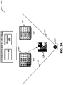
- a system 100 for managing interference between transmission sources in an Optical Camera Communication (OCC) network is illustrated in FIGs. 1A and 1B .
- the system 100 includes an inference management device 102, which is configured to manage interference between a transmission source 104 and a transmission source 106 as experienced by a camera 108 (or a User Equipment (UE)).
- Each of the transmission source 104 and the transmission source 106 may include a set of light sources.
- the transmission source 104 includes a set of light sources 110 and the transmission source 106 includes a set of light sources 112.
- Each of the set of lights sources 110 and 112 may be a matrix of Light Emitting Diode (LED) bulbs that are spatially arranged.
- the set of lights sources 110 and 112 may be a plurality of pixels.
- each of the transmission sources 104 and 106 may be display screens. Examples of display screens may include, but are not limited to LED screen, Liquid Crystal Display (LCD) screen, Organic LED (OLED) screen, or Active-Matrix OLED (AMOLED) screen.
- each light source within the set of lights sources 110 and 112 may be configured to display one of a plurality of colors.
- a dot matrix formed by either the LED bulbs or pixels may create a pattern that may encode information which is required to be transmitted to the camera 108.
- a unique pattern may be formed using one or more of on-off status and colors of pixels or LED bulbs.
- an input data (which may be text, image, or video) that needs to be transmitted to the camera 108, may be represented using a Quick Response (QR) code by a transmission source (for example, the transmission source 104).
- the transmission source may be a display screen and the pixels may be used to display the QR code, as an example of spatially arranged coding scheme that is used in OCC network.
- a transmission source 114 in FIG. 1B , depicts a screen displaying a QR code.
- the transmit area may either be dynamic or fixed.
- the QR code may either cover a portion of the display screen or the whole display screen, based on a current implementation.
- a set of color patterns may be used to encode information that is required to be transmitted.
- a transmission source may include an LED matrix (as depicted by the transmission sources 104 and 106) and the QR code may be a color pattern based QR code.
- the information to be transmitted may be encoded by color codes emitted by a set of spatially arranged LEDs in the LED matrix. A color emitted by each LED may carry a number of bits from the information to be transmitted. This may further vary based on the number of colors that may be decoded by the camera 108. It will be apparent to a person skilled in the art that if more number of colors may be used to encode the information, overall throughput of the system 100 may increase.
- the information encoded in a pattern displayed on a transmission source is received and read by the camera 108, which acts as a receiver.
- a capture area 116 of the camera 108 is depicted in FIG. 1A .
- the camera 108 may take the snap of the free space between the transmission sources 104 and 106.
- the camera 108 preserves the spatial information that may be used to decode the encoded information transmitted by one or more of the transmission sources 104 and 106.
- the information may be transmitted by the transmission sources 104 and 106 in the form of transmit frames.
- a transmission source includes an LED matrix, for example, the transmission source 104
- a transmit frame 118 may be transmitted.
- a receiver module (not shown in FIG. 1A ) within the camera 108 processes the transmit frame 118 captured by the camera 108 to decode the information thus transmitted by the transmission source 104. It will be apparent to a person skilled in the art that the receiver module may be located outside the camera 108.
- the camera 108 may receive transmit frames from both the transmission sources 104 and 106. This may lead to an interference experienced by the camera 108.
- the interference management device 102 which is in communication with the camera 108, may detect this interference. It will be apparent to a person skilled in the art that the interference management device 102 and the camera 108 may be located in separate devices. The communication between the camera 108 and the interference management device 102 is explained in detail in conjunction with FIG. 2 .
- the interference management device 102 may assign different guard bands to each of the transmission sources 104 and 106. As a result, each transmit frame may have a unique guard band.
- the interference management device 102 may additionally communicate the information regarding mapping of unique guard bands to respective transmission sources to the camera 108.
- the communication between the interference management device 102 and the camera 108 is explained in detail in conjunction with FIG. 2 .
- the transmission source 104 may be allocated a guard band having red color
- the transmission source 106 may be allocated a guard band having blue color.
- the camera 108 receives a transmit frame with a red guard band
- the camera 108 is able to identify that the transmission source 104 has transmitted the transmit frame.
- the camera 108 may be connected or attached to the transmission source 104.
- the camera 108 may accept the transmit frames transmitted by the transmission source 104 and may ignore the transmit frames transmitted by the transmission source 106.
- the camera 108 may accept transmit frames that have a red guard band and may reject/ignore transmit frames that have a blue guard band. As a result of the guard bands, the camera 108 is able to eliminate noise. This is further explained in detail in conjunction with FIG. 2 .
- the inference management device 102 includes a processor 120 that is communicatively coupled to a memory 122.
- the memory 122 may store instructions that, when executed by the processor 120, cause the processor 120 to manage interference between transmission sources, as discussed in greater detail in FIG. 2 to FIG. 8 .
- the memory 122 may be a non-volatile memory or a volatile memory. Examples of non-volatile memory, may include, but are not limited to a flash memory, a Read Only Memory (ROM), a Programmable ROM (PROM), Erasable PROM (EPROM), and Electrically EPROM (EEPROM) memory. Examples of volatile memory may include, but are not limited to Dynamic Random Access Memory (DRAM), and Static Random-Access memory (SRAM).
- DRAM Dynamic Random Access Memory
- SRAM Static Random-Access memory
- the transmission source 114 is shared by cameras 124, 126, and 128, as the transmission source 114 lies in the capture areas of each of the cameras 124, 126, and 128.
- the interference management device 102 may assign three separate orthogonal codes (e.g. orthogonal spreading codes) to each of the cameras 124, 126, and 128.
- the interference management device 102 may generate the following orthogonal codes [[1 1 1 1], [1 1 -1 -1], [1 -1 1 - 1]], as specified in the Code generation and allocation section of ETSI TS 125 213 V13.0.0 (2016-01 ) [UTMS Spreading and Modulation (FDD)].
- the interference management device 102 may then share these with the cameras 124, 126, and 128.
- the camera 124 may be assigned the orthogonal code: [1 1 1 1]
- the camera 126 may be assigned the orthogonal code: [1 1 -1 -1]
- the camera 128 may be assigned the orthogonal code: [1 -1 1 -1].
- the interference management device 102 is able to maintain orthogonality in the multi-user data which is transmitted using a single channel. It will be apparent to a person skilled in the art that the embodiment is not limited to three cameras. This is further explained in detail in conjunction with FIG. 3 .
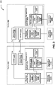
- each of the devices 202 and 204 may include any computing device that includes a camera and a transmission source (for example, one of the transmission sources 104, 106, and 114).
- the device 202 includes a memory 122a (analogous to the memory 122) that is communicatively coupled to a processor 120a (analogous to the processor 120).
- the memory 122a further includes a coordinator 206a and an encoding module 208a, which is communicatively coupled to the coordinator 206a.
- the coordinator 206a is further explained in detail in conjunction with FIG. 3 .
- the memory 122a and the processor 120a may be present inside an interference management device 102a (analogous to the interference management device 102).
- the memory 122a and the processor 120a may be located within any device of the OCC network.
- the coordinator 206a is further communicatively coupled to a transmission source 210awhich may be analogous to one of the transmission sources 104, 106, or 114.
- the device 202 may further include a camera 212a, which may be analogous to the camera 108.
- the camera 212a may further be communicatively coupled to a receiver module 214a.
- the receiver module 214a is depicted as being present outside the camera 212a, the receiver module 214a may be located within the camera 212a in some embodiments.
- the receiver module 214a further includes a processor 216a and a decoding module 218a.
- the device 204 includes a memory 122b (analogous to the memory 122) that is communicatively coupled to a processor 120b (analogous to the processor 120).
- the memory 122b further includes a coordinator 206b and an encoding module 208b, which is communicatively coupled to the coordinator 206b.
- the coordinator 206b is further explained in detail in conjunction with FIG. 3 .
- the memory 122b and the processor 120b may be present inside an interference management device 102b (analogous to the interference management device 102).
- the memory 122b and the processor 120b may be located within any device of the OCC network.
- the coordinator 206b is further communicatively coupled to a transmission source 210b, which may be analogous to one of the transmission sources 104, 106, or 114.
- the device 204 may further include a camera 212b, which may be analogous to the camera 108.
- the camera 212b may further be communicatively coupled to a receiver module 214b. Though the receiver module 214b is depicted as being present outside the camera 212b, the receiver module 214b may be located within the camera 212b in some embodiments.
- the receiver module 214b further includes a processor 216b and a decoding module 218b.
- the camera 212a and the transmission source 210b form a first transceiver pair, while the camera 212b and the transmission source 210a form a second transceiver pair.
- information transmitted by the transmission source 210b is received and decoded by the camera 212a in conjunction with the receiver module 214a.
- information transmitted by the transmission source 210a is received and decoded by the camera 212b in conjunction with the receiver module 214b.
- a transmitting application 220b which is communicatively coupled to the encoding module 208b, may want to transmit data to a receiving application 222a that is communicatively coupled to the camera 212a through the receiver module 214a.
- the transmitting application 220b shares the data with the encoding module 208b, which encodes the data to be transmitted based on a predetermined encoding pattern and the type of the transmission source 210b (i.e., a screen based transmission or an LED based transmission).
- the encoding module 208b then shares the encoded data with the coordinator 206b, which further communicates the encoded data to the transmission sources 210b.
- the transmission sources 210b then transmits the encoded data to the camera 212a.
- the decoding module 218a in the receiver module 214a decodes the encoded data to extract the information. The information is then shared with the receiving application 222a. Additionally, using a closed feedback loop, the decoding module 218a shares the decoded information with the coordinator 206a. Based on the decoded information, the coordinator 206a may determine whether the camera 212a is experiencing interference, as a result of multiple transmission sources within its capture area. The detection of interference may be communicated to the device 204, through the second transceiver pair, i.e., the transmission source 210a and the camera 212b. The decoding module 218b may share information associated with interference detection with the coordinator 206b, which may then manage the interference by assigning unique guard bands. This is further explained in detail in conjunction with FIG. 3 , FIG.4 , and FIG. 5 .
- a transmitting application 220a which is communicatively coupled to the encoding module 208a, may want to transmit data to a receiving application 222b that is communicatively coupled to the camera 212b through the receiver module 214b.
- a similar mechanism as detailed in the example above is followed in this case as well.
- the coordinator 206 is analogous to each of the coordinators 206a and 206b.
- the coordinator 206 includes a UE registration block 302, an interference management unit 304, and a multi user support block 306.
- the UE registration block 302 extracts and stores information of cameras (or UEs) in the vicinity of each of transmission source in order to perform one or more functionalities, which may include, but are not limited to providing multiple access, seamless handover to another transmission source, or interference detection. Additionally, the UE registration block 302 may include information of cameras (or UEs) that may have come in vicinity of a transmission source with connectivity requests.
- the interference management unit 304 detects interference between a set of transmission sources and performs different techniques to manage and mitigate the interference and provide communication to cameras within an interference region.
- the functionality of the interference management unit 304 is further explained in detail in conjunction with FIG. 4 to FIG. 8 .
- the multi user support block 306 provides multi-user support to the cameras (present both in overlapping and non-overlapping regions) in the vicinity using multiple access techniques (for example, CDMA).
- the multi user support block 306 may enable handling of multiple cameras attached to a single transmission sources by applying multiple access techniques to the camera. This has already been explained in conjunction with FIG. 1 .
- each of the cameras 124, 126, and 128 may be registered in the UE registration block 302. Based on the number of users, the multi user support block 306 may generate orthogonal codes for each of the cameras 124, 126, and 128 and thus maintain orthogonality among the cameras 124, 126, and 128.
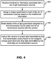
- the interference management device 102 may receive interference information associated with a set of transmission sources (for example, transmission sources 104 and 106).
- the interference information may be received from a camera (for example, the camera 108).
- the coordinator 206 within the interference management device 102 may receive the interference information from the camera 108.
- Each of the set of transmission sources are within a capture area of the camera 108.
- each of the set of transmission sources may include a set of light sources that are configured to display one of a plurality of colors.
- the transmission source 104 includes the set of light sources 110 and the transmission source 106 includes the set of light sources 112. This has been already been explained in detail in conjunction with FIG. 1 .
- the interference management device 102 assigns a unique guard band to each of the set of transmission sources.
- the coordinator 206 assigns a unique guard band.
- the coordinator 206 may assign a reg guard band to the transmission source 104 and a blue guard band to the transmission source 106.
- a transmit frame from the transmission source 104 is fully surrounded by the red guard band and a transmit frame from the transmission source 106 is fully surrounded by the blue guard band.
- the interference between transmit frames from different transmission sources 104 and 106 may be accomplished by using different colored guard bands.
- the camera (for example, the camera 108) is configured as the receiver of a first transmission source within the set of transmission sources (for example, the transmission source 104). In other words, the camera is communicatively coupled to the first transmission source, as explained in detail in conjunction with FIG. 2 .
- the interference management device 102 may share details of the unique guard band assigned to the first transmission source (for example, the transmission source 104) with the camera (for example, the camera 108).
- the coordinator 206 may share with the camera 108 that a red guard band has been assigned to the transmission source 104.
- the communication between the coordinator 206 and the camera 108 with regards to the guard bands may be in conformance with the communication mechanism explained in FIG. 2 .
- the interference management device 102 may instruct the camera (for example, the camera 108), at step 408, to accept data transmitted by the first transmission source based on the assigned unique guard band and drop data transmitted by the remaining set of transmission sources. These instruction may be sent using the communication mechanism explained in FIG. 2 .
- the coordinator 206 may send these instructions to the camera.
- the coordinator 206 may instruct the camera 108 to accept transmit frames that have a red guard band and to drop transmit frames that have a blue guard band. This is further explained in detail in conjunction with FIG. 5 .
- the camera 108 sends an interference message to the interference management unit 304 in the coordinator 206.
- the interference message may include a message for informing a sender of a receiver's state, e.g. a Negative Acknowledgment (NACK) for rejecting a previously received message or indicating some kind of error.
- the interference message may include information related to interference between the transmission sources 104 and 106 as detected by the camera 108.
- the interference management unit 304 may assign a red guard band to the transmission source 104, at 504, and a blue guard band to the transmission source 106, at 506.
- the interference management unit 304 may share the information regarding guard band assignment with the camera 108 and may also instruct the camera 108 to accept transmit frames with red guard bands and drop transmit frames with blue guard bands.
- the camera 108 responds back with an Acknowledgement (ACK) message to the interference management unit 304, indicating that the camera 108 is not experiencing any interference.
- ACK Acknowledgement
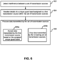
- the data transmitted by the set of transmission sources is processed by a camera (for example, the camera 108).
- the camera detects interference between the set of transmission sources by the camera.
- the camera receives details of a unique guard band assigned to a first transmission source (for example, the transmission source 104) within the set of transmission sources. This has already been explained in detail in conjunction with FIG. 4 .
- the camera processes data transmitted by the set of transmission sources.
- the data may be processed by accepting, at step 606a, data transmitted by the first transmission source based on the assigned unique guard band. Additionally or alternatively, the camera, at step 606b, may drop data transmitted by the remaining set of transmission sources. This has already been explained in detail in conjunction with FIG. 4 .
- the interference management device 102 instructs the camera (for example, the camera 108) to accept data transmitted by the first transmission source (for example, the transmission source 104) based on an assigned unique guard band and drop data transmitted by the remaining set of transmission sources (for example, the transmission source 104).
- the interference management device 102 may receive a Channel Quality Indicator (CQI) for each of the set of transmission sources from the camera (e.g.
- CQI Channel Quality Indicator
- the interference management device 102 may receive a CQI which is an indicator carrying information on how good/bad the communication channel quality is for the communication channel between the camera and each of the set of transmission sources).
- a CQI for an associated transmission source may be calculated based on Packet Error Ratio (PER) of the associated transmission source.
- PER Packet Error Ratio
- the CQI for the transmission source 104 may be computed based on a PER for the transmission source 104.
- the interference management device 102 identifies a second transmission source (for example, the transmission source 106) that has the highest CQI amongst the set of transmission sources (or the highest CQI among the rest of transmission sources from the set).
- the interference management device 102 performs handover of the camera from the first transmission source to the second transmission source (e.g. a handover or change of which transmission source's data the camera is configured to receive or which transmission source transmits data for the camera, i.e. after the handover the camera is configured to receive data from the second transmission source instead of the first transmission source). This is further explained in detail in conjunction with FIG. 8 .
- a communication flow 800 between the camera 108, the transmission sources 104 and 106, and the interference management unit 304 for handover of the camera 108 from the transmission source 104 to the transmission source 106 is illustrated, in accordance with an embodiment.
- the camera 108 is attached or connected to the transmission source 104.
- the interference management unit 304 instructs the transmission source 104 to send a test frame along with the assigned guard band to the camera 108.
- the transmission sources 104 sends a test frame to the camera 108.
- the camera 108 sends a PER value to the transmission source 104, which shares the PER value with the interference management unit 304.
- the interference management unit 304 instructs the transmission source 106 to send a test frame along with the assigned guard band to the camera 108.
- the transmission sources 106 sends a test frame to the camera 108.
- the camera 108 sends a PER value to the transmission source 106, which further shares the PER value with the interference management unit 304.
- the interference management unit 304 determines the CQI associated with each of the transmission sources 104 and 106. In this case, the CQI associated with the transmission source 106 is higher than the CQI associated with the transmission source 104. Thus, the interference management unit 304, at 810, instructs the camera 108, via the transmission source 104, to handover to the transmission source 106. It will be apparent to a person skilled in the art that such handover of the camera 108 may iteratively be executed based on CQI associated with each of the transmission sources 104 and 106.
- the above described techniques may take the form of computer or controller implemented processes and apparatuses for practicing those processes.
- the disclosure can also be embodied in the form of computer program code containing instructions embodied in tangible media, such as floppy diskettes, solid state drives, CD-ROMs, hard drives, or any other computer-readable storage medium, wherein, when the computer program code is loaded into and executed by a computer or controller, the computer becomes an apparatus for practicing the invention.
- the disclosure may also be embodied in the form of computer program code or signal, for example, whether stored in a storage medium, loaded into and/or executed by a computer or controller, or transmitted over some transmission medium, such as over electrical wiring or cabling, through fiber optics, or via electromagnetic radiation, wherein, when the computer program code is loaded into and executed by a computer, the computer becomes an apparatus for practicing the invention.
- the computer program code segments configure the microprocessor to create specific logic circuits.
- One or more techniques described in the various embodiments discussed above provide for interference detection due to multiple transmit sources in a capture area, using the help of receiver camera.
- the various embodiments also provide for interference mitigation using guard bands in order to overcome interference due to multiple transmit sources.
- a smart handover technique is further provided that initiates handover at any point of time after the initiation of data transmission based on channel conditions.
- the various embodiments provide for multi-user support using CDMA technique for single carrier as well as multi-carrier transmit signals.
- a computer-readable storage medium refers to any type of physical memory on which information or data readable by a processor may be stored.
- a computer-readable storage medium may store instructions for execution by one or more processors, including instructions for causing the processor(s) to perform steps or stages consistent with the embodiments described herein.
- the term "computer-readable medium” should be understood to include tangible items and exclude carrier waves and transient signals, i.e., be non-transitory. Examples include random access memory (RAM), read-only memory (ROM), volatile memory, nonvolatile memory, hard drives, CD ROMs, DVDs, flash drives, disks, and any other known physical storage media.
Landscapes
- Engineering & Computer Science (AREA)
- Signal Processing (AREA)
- Computer Networks & Wireless Communication (AREA)
- Physics & Mathematics (AREA)
- Electromagnetism (AREA)
- Multimedia (AREA)
- Mobile Radio Communication Systems (AREA)
Abstract
Description
- This disclosure relates generally to Optical Camera Communication (OCC) networks, and more particularly to a device, a camera, a system and method for managing interference between transmission sources in an optical camera communication network.
- The demand for wireless data communication is increasing at a very high rate. To keep up with this growing demand, the available Radio Frequency (RF) spectrum of below 10 GHz may not be sufficient. As an alternative, Optical Wireless Communication (OWC) involves communication over a light channel by a transmit-receive (transceiver) pair. The transceiver pair can transmit information using a Light Emitting Diode (LED) and receive information using a light sensor, such as, a photo diode or a camera.
- Optical Camera Communication (OCC) may be one of the forms of OWC. The OCC involves a camera that is used to decode information received from a transmitter. The transmitter transmits the information by encoding it in a spatially arranged color codes. Thus, while information transmission is based on emitting the encoded frames in color codes, reception is based on capturing the image of the transmitted information and extracting the spatial information which could be used to decode transmitted data.
- The OCC may further include a screen based transmission scheme and an LED based transmission scheme. In a screen based transmission scheme, a set of color patterns may be used to encode information that is to be transmitted. As an example of spatially arranged coding scheme used in OCC, a Quick Response (QR) code based communication may be used that displays OR codes on a display screen. In this scheme, the information to be transmitted may be broken up into smaller blocks to generate a sequence of QR codes. Each QR code in the sequence may be displayed for a small time-interval before the next QR code in the sequence is displayed. The display interval for a QR code in the sequence may be based on a capture rate of the camera.
- In the LED based transmission scheme, the information to be transmitted is encoded by color codes emitted by a set of spatially arranged LEDs. In this case, the color emitted by each LED may carry a number of bits from the information block depending on the number of colors that may be decoded by a receiving camera. If more number of colors are used to encode the information, the overall throughput may increase. The receiving camera sensitivity, distance between the transceivers, background illumination, and media condition play a key role in determining how many colors may be used to encode the transmitted information.
- However, in the OCC, when there are two or more transmission sources in the capture area of a receiver camera, there is no existing systems to mitigate the interference cause under this scenario. Moreover, in the interference region, there is no method to detect physical cell Identifiers (IDs) of the transmission sources associated with the receiver camera. As a result, when a user associated with the receiver camera comes in the vicinity of multiple such transmission sources, the user may not be able to communicate with an intended transmission source in the interference region. Hence, interference management and multi-access in the interference region within the OCC systems remains a key challenge.
- In one embodiment, a method for managing interference between transmission sources in an Optical Camera Communication (OCC) network is disclosed. The method includes receiving, by an interference management device, interference information associated with a set of transmission sources, wherein each of the set of transmission sources are within a capture area of a camera. Each of the set of transmission sources comprises a set of light sources configured to display one of a plurality of colors. The method further includes assigning, by the interference management device, a unique guard band to each of the set of transmission sources based on the interference information. The method includes sharing, by the interference management device, details of the unique guard band assigned to a first transmission source within the set of transmission sources with the camera. The camera is configured as the receiver of the first transmission source. The method further includes instructing, by the interference management device, the camera to accept data transmitted by the first transmission source based on the assigned unique guard band and drop data transmitted by the remaining set of transmission sources.
- In another embodiment, a method for managing interference between transmission sources in an OCC network is disclosed. The method includes detecting, by a camera based receiver, interference from a set of transmission sources. Each of the set of transmission sources are within a capture area of a camera associated with the camera based receiver. Each of the set of transmission sources comprises a set of lights configured to display one of a plurality of colors. The method further includes receiving, by the receiver camera, details of a unique guard band assigned to a first transmission source within the set of transmission sources. The camera is configured to receive the first transmission source, and wherein each of the set of transmission sources is assigned a unique guard band. The method includes processing, by the receiver associated with a camera, data transmitted by the set of transmission sources. The processing includes accepting data transmitted by the first transmission source based on the assigned unique guard band and dropping data transmitted by the remaining set of transmission sources.
- In another embodiment, a system for managing interference between transmission sources in an OCC network is disclosed. The system includes a processor and a memory communicatively coupled to the processor, wherein the memory stores processor instructions, which, on execution, causes the processor to receive interference information associated with a set of transmission sources. Each of the set of transmission sources are within a capture area of a camera. Each of the set of transmission sources comprises a set of light sources configured to display one of a plurality of colors. The processor instructions further cause the processor to assign a unique guard band to each of the set of transmission sources based on the interference information. The processor instructions cause the processor to share details of the unique guard band assigned to a first transmission source within the set of transmission sources with the camera, wherein the camera is configured as the receiver of the first transmission source. The processor instructions further cause the processor to instruct the camera to accept data transmitted by the first transmission source based on the assigned unique guard band and drop data transmitted by the remaining set of transmission sources.
- In yet another embodiment, a camera is disclosed. The camera includes a processor and a memory communicatively coupled to the processor, wherein the memory stores processor instructions, which, on execution, causes the processor to detect interference from a set of transmission sources. Each of the set of transmission sources are within a capture area of a camera associated with the camera based receiver. Each of the set of transmission sources comprises a set of lights configured to display one of a plurality of colors. The processor instructions further cause the processor to receive details of a unique guard band assigned to a first transmission source within the set of transmission sources. The camera is configured to receive the first transmission source. Each of the set of transmission sources is assigned a unique guard band. The processor instructions cause the processor to process data transmitted by the set of transmission sources, wherein to process the data, the processor instructions further cause the processor to accept data transmitted by the first transmission source based on the assigned unique guard band and drop data transmitted by the remaining set of transmission sources.
- It is to be understood that both the foregoing general description and the following detailed description are exemplary and explanatory only and are not restrictive of the invention, as claimed.
- The accompanying drawings, which are incorporated in and constitute a part of this disclosure, illustrate exemplary embodiments and, together with the description, serve to explain the disclosed principles.
-
FIGs. 1A and1B illustrate a system for managing interference between transmission sources in an Optical Camera Communication (OCC) network, in accordance with some embodiments. -
FIG. 2 illustrates a functional block diagram of a system for managing interference between transmission sources within a first device and a second device in an OCC network, in accordance with an embodiment. -
FIG. 3 illustrates a functional block diagram of a coordinator for managing interference between transmission sources in an OCC network, in accordance with an embodiment. -
FIG. 4 illustrates a flowchart of a method for managing interference between transmission sources in an OCC network, in accordance with an embodiment. -
FIG. 5 illustrates a communication flow between a camera, two transmission sources, and an interference management unit for detection and management of interference between the two transmission sources, in accordance with an exemplary embodiment. -
FIG. 6 illustrates a flowchart of a method for processing data transmitted by a set of transmission sources, in accordance with an embodiment. -
FIG. 7 illustrates a flowchart of a method for handover of a camera from a first transmission source to a second transmission source, in accordance with an embodiment. -
FIG. 8 illustrates a communication flow between a camera, two transmission sources, and an interference management unit for handover of the camera from a first transmission source to a second transmission source, in accordance with an embodiment. - Exemplary embodiments are described with reference to the accompanying drawings. Wherever convenient, the same reference numbers are used throughout the drawings to refer to the same or like parts. While examples and features of disclosed principles are described herein, modifications, adaptations, and other implementations are possible without departing from the scope of the disclosed embodiments. It is intended that the following detailed description be considered as exemplary only, with the true scope being indicated by the following claims. Additional illustrative embodiments are listed below.
- In some embodiment, a
system 100 for managing interference between transmission sources in an Optical Camera Communication (OCC) network is illustrated inFIGs. 1A and1B . Thesystem 100 includes aninference management device 102, which is configured to manage interference between atransmission source 104 and atransmission source 106 as experienced by a camera 108 (or a User Equipment (UE)). Each of thetransmission source 104 and thetransmission source 106 may include a set of light sources. By way of an example, thetransmission source 104 includes a set oflight sources 110 and thetransmission source 106 includes a set oflight sources 112. - Each of the set of
lights sources lights sources transmission sources lights sources camera 108. In both the implementations, i.e., the LED bulbs and the pixels, a unique pattern may be formed using one or more of on-off status and colors of pixels or LED bulbs. - By way of an example, an input data (which may be text, image, or video) that needs to be transmitted to the
camera 108, may be represented using a Quick Response (QR) code by a transmission source (for example, the transmission source 104). In one scenario, the transmission source may be a display screen and the pixels may be used to display the QR code, as an example of spatially arranged coding scheme that is used in OCC network. Atransmission source 114, inFIG. 1B , depicts a screen displaying a QR code. In this case, the transmit area may either be dynamic or fixed. In other words, the QR code may either cover a portion of the display screen or the whole display screen, based on a current implementation. Further, in this scenario, a set of color patterns may be used to encode information that is required to be transmitted. - In another scenario, a transmission source may include an LED matrix (as depicted by the
transmission sources 104 and 106) and the QR code may be a color pattern based QR code. In this case, the information to be transmitted may be encoded by color codes emitted by a set of spatially arranged LEDs in the LED matrix. A color emitted by each LED may carry a number of bits from the information to be transmitted. This may further vary based on the number of colors that may be decoded by thecamera 108. It will be apparent to a person skilled in the art that if more number of colors may be used to encode the information, overall throughput of thesystem 100 may increase. - The information encoded in a pattern displayed on a transmission source is received and read by the
camera 108, which acts as a receiver. Acapture area 116 of thecamera 108 is depicted inFIG. 1A . Thecamera 108 may take the snap of the free space between thetransmission sources camera 108 preserves the spatial information that may be used to decode the encoded information transmitted by one or more of thetransmission sources transmission sources transmission source 104, a transmitframe 118 may be transmitted. A receiver module (not shown inFIG. 1A ) within thecamera 108 processes the transmitframe 118 captured by thecamera 108 to decode the information thus transmitted by thetransmission source 104. It will be apparent to a person skilled in the art that the receiver module may be located outside thecamera 108. - However, since the
capture area 116 of thecamera 108 covers both thetransmission sources camera 108 may receive transmit frames from both thetransmission sources camera 108. Theinterference management device 102, which is in communication with thecamera 108, may detect this interference. It will be apparent to a person skilled in the art that theinterference management device 102 and thecamera 108 may be located in separate devices. The communication between thecamera 108 and theinterference management device 102 is explained in detail in conjunction withFIG. 2 . In order to mitigate and manage the interference thus detected, theinterference management device 102 may assign different guard bands to each of thetransmission sources - The
interference management device 102 may additionally communicate the information regarding mapping of unique guard bands to respective transmission sources to thecamera 108. The communication between theinterference management device 102 and thecamera 108 is explained in detail in conjunction withFIG. 2 . By way of an example, thetransmission source 104 may be allocated a guard band having red color, while thetransmission source 106 may be allocated a guard band having blue color. As a result, when thecamera 108 receives a transmit frame with a red guard band, thecamera 108 is able to identify that thetransmission source 104 has transmitted the transmit frame. Moreover, thecamera 108 may be connected or attached to thetransmission source 104. Thus, thecamera 108 may accept the transmit frames transmitted by thetransmission source 104 and may ignore the transmit frames transmitted by thetransmission source 106. To this end, thecamera 108 may accept transmit frames that have a red guard band and may reject/ignore transmit frames that have a blue guard band. As a result of the guard bands, thecamera 108 is able to eliminate noise. This is further explained in detail in conjunction withFIG. 2 . - In order to manage and further mitigate the interference between the
transmission sources inference management device 102 includes aprocessor 120 that is communicatively coupled to amemory 122. Thememory 122 may store instructions that, when executed by theprocessor 120, cause theprocessor 120 to manage interference between transmission sources, as discussed in greater detail inFIG. 2 to FIG. 8 . Thememory 122 may be a non-volatile memory or a volatile memory. Examples of non-volatile memory, may include, but are not limited to a flash memory, a Read Only Memory (ROM), a Programmable ROM (PROM), Erasable PROM (EPROM), and Electrically EPROM (EEPROM) memory. Examples of volatile memory may include, but are not limited to Dynamic Random Access Memory (DRAM), and Static Random-Access memory (SRAM). - Referring now to
FIG. 1B , thetransmission source 114 is shared bycameras transmission source 114 lies in the capture areas of each of thecameras interference management device 102 identifies interference, theinterference management device 102 may assign three separate orthogonal codes (e.g. orthogonal spreading codes) to each of thecameras interference management device 102 may generate the following orthogonal codes [[1 1 1 1], [1 1 -1 -1], [1 -1 1 - 1]], as specified in the Code generation and allocation section of ETSI TS 125 213 V13.0.0 (2016-01) [UTMS Spreading and Modulation (FDD)]. Theinterference management device 102 may then share these with thecameras camera 124 may be assigned the orthogonal code: [1 1 1 1], thecamera 126 may be assigned the orthogonal code: [1 1 -1 -1], and thecamera 128 may be assigned the orthogonal code: [1 -1 1 -1]. By using the orthogonal codes, theinterference management device 102 is able to maintain orthogonality in the multi-user data which is transmitted using a single channel. It will be apparent to a person skilled in the art that the embodiment is not limited to three cameras. This is further explained in detail in conjunction withFIG. 3 . - Referring now to
FIG. 2 , a functional block diagram of asystem 200 for managing interference between transmission sources within adevice 202 and adevice 204 in an OCC network is illustrated, in accordance with an embodiment. Examples of each of thedevices transmission sources device 202 includes amemory 122a (analogous to the memory 122) that is communicatively coupled to aprocessor 120a (analogous to the processor 120). Thememory 122a further includes acoordinator 206a and anencoding module 208a, which is communicatively coupled to thecoordinator 206a. Thecoordinator 206a is further explained in detail in conjunction withFIG. 3 . As is apparent from theFIG. 2 , thememory 122a and theprocessor 120a may be present inside an interference management device 102a (analogous to the interference management device 102). Alternatively, thememory 122a and theprocessor 120a may be located within any device of the OCC network. Thecoordinator 206a is further communicatively coupled to a transmission source 210awhich may be analogous to one of thetransmission sources device 202 may further include acamera 212a, which may be analogous to thecamera 108. Thecamera 212a may further be communicatively coupled to areceiver module 214a. Though thereceiver module 214a is depicted as being present outside thecamera 212a, thereceiver module 214a may be located within thecamera 212a in some embodiments. Thereceiver module 214a further includes aprocessor 216a and adecoding module 218a. - In a similar manner, the
device 204 includes amemory 122b (analogous to the memory 122) that is communicatively coupled to aprocessor 120b (analogous to the processor 120). Thememory 122b further includes a coordinator 206b and anencoding module 208b, which is communicatively coupled to the coordinator 206b. The coordinator 206b is further explained in detail in conjunction withFIG. 3 . As is apparent from theFIG. 2 , thememory 122b and theprocessor 120b may be present inside an interference management device 102b (analogous to the interference management device 102). Alternatively, thememory 122b and theprocessor 120b may be located within any device of the OCC network. The coordinator 206b is further communicatively coupled to atransmission source 210b, which may be analogous to one of thetransmission sources device 204 may further include acamera 212b, which may be analogous to thecamera 108. Thecamera 212b may further be communicatively coupled to areceiver module 214b. Though thereceiver module 214b is depicted as being present outside thecamera 212b, thereceiver module 214b may be located within thecamera 212b in some embodiments. Thereceiver module 214b further includes aprocessor 216b and adecoding module 218b. - In the
system 200, thecamera 212a and thetransmission source 210b form a first transceiver pair, while thecamera 212b and thetransmission source 210a form a second transceiver pair. In other words, information transmitted by thetransmission source 210b is received and decoded by thecamera 212a in conjunction with thereceiver module 214a. In a similar manner, information transmitted by thetransmission source 210a is received and decoded by thecamera 212b in conjunction with thereceiver module 214b. - By way of an example, a transmitting
application 220b, which is communicatively coupled to theencoding module 208b, may want to transmit data to a receivingapplication 222a that is communicatively coupled to thecamera 212a through thereceiver module 214a. To this end, the transmittingapplication 220b shares the data with theencoding module 208b, which encodes the data to be transmitted based on a predetermined encoding pattern and the type of thetransmission source 210b (i.e., a screen based transmission or an LED based transmission). Theencoding module 208b then shares the encoded data with the coordinator 206b, which further communicates the encoded data to thetransmission sources 210b. Thetransmission sources 210b then transmits the encoded data to thecamera 212a. Methods of transmitting data from a transmission source to a camera have been explained in detail in conjunction withFIG. 1 . - Once the
camera 212a receives the encoded data as transmit frames, thedecoding module 218a in thereceiver module 214a decodes the encoded data to extract the information. The information is then shared with the receivingapplication 222a. Additionally, using a closed feedback loop, thedecoding module 218a shares the decoded information with thecoordinator 206a. Based on the decoded information, thecoordinator 206a may determine whether thecamera 212a is experiencing interference, as a result of multiple transmission sources within its capture area. The detection of interference may be communicated to thedevice 204, through the second transceiver pair, i.e., thetransmission source 210a and thecamera 212b. Thedecoding module 218b may share information associated with interference detection with the coordinator 206b, which may then manage the interference by assigning unique guard bands. This is further explained in detail in conjunction withFIG. 3 ,FIG.4 , andFIG. 5 . - By way of another example, a transmitting
application 220a, which is communicatively coupled to theencoding module 208a, may want to transmit data to a receivingapplication 222b that is communicatively coupled to thecamera 212b through thereceiver module 214b. A similar mechanism as detailed in the example above is followed in this case as well. - Referring now to
FIG. 3 , a functional block diagram of acoordinator 206 for managing interference between transmission sources in an OCC network is illustrated, in accordance with an embodiment. Thecoordinator 206 is analogous to each of thecoordinators 206a and 206b. Thecoordinator 206 includes aUE registration block 302, aninterference management unit 304, and a multi user support block 306. TheUE registration block 302 extracts and stores information of cameras (or UEs) in the vicinity of each of transmission source in order to perform one or more functionalities, which may include, but are not limited to providing multiple access, seamless handover to another transmission source, or interference detection. Additionally, theUE registration block 302 may include information of cameras (or UEs) that may have come in vicinity of a transmission source with connectivity requests. - The
interference management unit 304 detects interference between a set of transmission sources and performs different techniques to manage and mitigate the interference and provide communication to cameras within an interference region. The functionality of theinterference management unit 304 is further explained in detail in conjunction withFIG. 4 to FIG. 8 . The multi user support block 306 provides multi-user support to the cameras (present both in overlapping and non-overlapping regions) in the vicinity using multiple access techniques (for example, CDMA). The multi user support block 306 may enable handling of multiple cameras attached to a single transmission sources by applying multiple access techniques to the camera. This has already been explained in conjunction withFIG. 1 . Also, referring back toFIG. 1 , each of thecameras UE registration block 302. Based on the number of users, the multi user support block 306 may generate orthogonal codes for each of thecameras cameras - Referring now to
FIG. 4 , a flowchart of a method for managing interference between transmission sources in an OCC network is illustrated, in accordance with an embodiment. Atstep 402, theinterference management device 102 may receive interference information associated with a set of transmission sources (for example,transmission sources 104 and 106). The interference information may be received from a camera (for example, the camera 108). In an embodiment, thecoordinator 206 within theinterference management device 102 may receive the interference information from thecamera 108. Each of the set of transmission sources are within a capture area of thecamera 108. Further, each of the set of transmission sources may include a set of light sources that are configured to display one of a plurality of colors. By way of an example, thetransmission source 104 includes the set oflight sources 110 and thetransmission source 106 includes the set oflight sources 112. This has been already been explained in detail in conjunction withFIG. 1 . - Based on the interference information, the
interference management device 102, atstep 404, assigns a unique guard band to each of the set of transmission sources. In an embodiment, thecoordinator 206 assigns a unique guard band. By way of an example, for thetransmission sources coordinator 206 may assign a reg guard band to thetransmission source 104 and a blue guard band to thetransmission source 106. In one example, a transmit frame from thetransmission source 104 is fully surrounded by the red guard band and a transmit frame from thetransmission source 106 is fully surrounded by the blue guard band. In this case, the interference between transmit frames fromdifferent transmission sources FIG. 2 . Atstep 406, theinterference management device 102 may share details of the unique guard band assigned to the first transmission source (for example, the transmission source 104) with the camera (for example, the camera 108). By way of an example, thecoordinator 206 may share with thecamera 108 that a red guard band has been assigned to thetransmission source 104. The communication between thecoordinator 206 and thecamera 108 with regards to the guard bands may be in conformance with the communication mechanism explained inFIG. 2 . - Thereafter, the
interference management device 102 may instruct the camera (for example, the camera 108), atstep 408, to accept data transmitted by the first transmission source based on the assigned unique guard band and drop data transmitted by the remaining set of transmission sources. These instruction may be sent using the communication mechanism explained inFIG. 2 . In an embodiment, thecoordinator 206 may send these instructions to the camera. By way of an example, since thecamera 108 is attached to thetransmission source 104, thecoordinator 206 may instruct thecamera 108 to accept transmit frames that have a red guard band and to drop transmit frames that have a blue guard band. This is further explained in detail in conjunction withFIG. 5 . - Referring now to
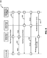
FIG. 5 , acommunication flow 500 between thecamera 108, thetransmission sources interference management unit 304 for detection and management of interference between thetransmission sources camera 108 sends an interference message to theinterference management unit 304 in thecoordinator 206. The interference message may include a message for informing a sender of a receiver's state, e.g. a Negative Acknowledgment (NACK) for rejecting a previously received message or indicating some kind of error. The interference message may include information related to interference between thetransmission sources camera 108. In response, theinterference management unit 304 may assign a red guard band to thetransmission source 104, at 504, and a blue guard band to thetransmission source 106, at 506. - Further, at 508, the
interference management unit 304 may share the information regarding guard band assignment with thecamera 108 and may also instruct thecamera 108 to accept transmit frames with red guard bands and drop transmit frames with blue guard bands. At 510, thecamera 108 responds back with an Acknowledgement (ACK) message to theinterference management unit 304, indicating that thecamera 108 is not experiencing any interference. - Referring now to
FIG. 6 , a flowchart of a method for processing data transmitted by a set of transmission sources after detection of interference between the set of transmission sources is illustrated, in accordance with an embodiment. In an embodiment, the data transmitted by the set of transmission sources is processed by a camera (for example, the camera 108). Atstep 602, the camera detects interference between the set of transmission sources by the camera. Atstep 604, the camera receives details of a unique guard band assigned to a first transmission source (for example, the transmission source 104) within the set of transmission sources. This has already been explained in detail in conjunction withFIG. 4 . - At
step 606, the camera processes data transmitted by the set of transmission sources. The data may be processed by accepting, atstep 606a, data transmitted by the first transmission source based on the assigned unique guard band. Additionally or alternatively, the camera, atstep 606b, may drop data transmitted by the remaining set of transmission sources. This has already been explained in detail in conjunction withFIG. 4 . - Referring now to
FIG. 7 , a flowchart of a method for handover of a camera from a first transmission source to a second transmission source is illustrated, in accordance with an embodiment. Atstep 702, theinterference management device 102 instructs the camera (for example, the camera 108) to accept data transmitted by the first transmission source (for example, the transmission source 104) based on an assigned unique guard band and drop data transmitted by the remaining set of transmission sources (for example, the transmission source 104). Atstep 704, theinterference management device 102 may receive a Channel Quality Indicator (CQI) for each of the set of transmission sources from the camera (e.g. theinterference management device 102 may receive a CQI which is an indicator carrying information on how good/bad the communication channel quality is for the communication channel between the camera and each of the set of transmission sources). A CQI for an associated transmission source may be calculated based on Packet Error Ratio (PER) of the associated transmission source. By way of an example, the CQI for thetransmission source 104 may be computed based on a PER for thetransmission source 104. - At
step 706, theinterference management device 102 identifies a second transmission source (for example, the transmission source 106) that has the highest CQI amongst the set of transmission sources (or the highest CQI among the rest of transmission sources from the set). Atstep 708, theinterference management device 102 performs handover of the camera from the first transmission source to the second transmission source (e.g. a handover or change of which transmission source's data the camera is configured to receive or which transmission source transmits data for the camera, i.e. after the handover the camera is configured to receive data from the second transmission source instead of the first transmission source). This is further explained in detail in conjunction withFIG. 8 . - Referring now to
FIG. 8 , acommunication flow 800 between thecamera 108, thetransmission sources interference management unit 304 for handover of thecamera 108 from thetransmission source 104 to thetransmission source 106 is illustrated, in accordance with an embodiment. Thecamera 108 is attached or connected to thetransmission source 104. At 802, theinterference management unit 304 instructs thetransmission source 104 to send a test frame along with the assigned guard band to thecamera 108. On receipt of these instructions, thetransmission sources 104 sends a test frame to thecamera 108. Based on the test frame, at 804, thecamera 108 sends a PER value to thetransmission source 104, which shares the PER value with theinterference management unit 304. - In a similar manner, at 806, the
interference management unit 304 instructs thetransmission source 106 to send a test frame along with the assigned guard band to thecamera 108. On receipt of these instructions, thetransmission sources 106 sends a test frame to thecamera 108. Based on the test frame, at 808, thecamera 108 sends a PER value to thetransmission source 106, which further shares the PER value with theinterference management unit 304. - Once the
interference management unit 304 receives the PER values associated with thetransmission sources interference management unit 304 determines the CQI associated with each of thetransmission sources transmission source 106 is higher than the CQI associated with thetransmission source 104. Thus, theinterference management unit 304, at 810, instructs thecamera 108, via thetransmission source 104, to handover to thetransmission source 106. It will be apparent to a person skilled in the art that such handover of thecamera 108 may iteratively be executed based on CQI associated with each of thetransmission sources - As will be also appreciated, the above described techniques may take the form of computer or controller implemented processes and apparatuses for practicing those processes. The disclosure can also be embodied in the form of computer program code containing instructions embodied in tangible media, such as floppy diskettes, solid state drives, CD-ROMs, hard drives, or any other computer-readable storage medium, wherein, when the computer program code is loaded into and executed by a computer or controller, the computer becomes an apparatus for practicing the invention. The disclosure may also be embodied in the form of computer program code or signal, for example, whether stored in a storage medium, loaded into and/or executed by a computer or controller, or transmitted over some transmission medium, such as over electrical wiring or cabling, through fiber optics, or via electromagnetic radiation, wherein, when the computer program code is loaded into and executed by a computer, the computer becomes an apparatus for practicing the invention. When implemented on a general-purpose microprocessor, the computer program code segments configure the microprocessor to create specific logic circuits.
- It will be appreciated that, for clarity purposes, the above description has described embodiments of the invention with reference to different functional units and processors. However, it will be apparent that any suitable distribution of functionality between different functional units, processors or domains may be used without detracting from the invention. For example, functionality illustrated to be performed by separate processors or controllers may be performed by the same processor or controller. Hence, references to specific functional units are only to be seen as references to suitable means for providing the described functionality, rather than indicative of a strict logical or physical structure or organization.
- One or more techniques described in the various embodiments discussed above provide for interference detection due to multiple transmit sources in a capture area, using the help of receiver camera. The various embodiments also provide for interference mitigation using guard bands in order to overcome interference due to multiple transmit sources. A smart handover technique is further provided that initiates handover at any point of time after the initiation of data transmission based on channel conditions. Moreover, the various embodiments provide for multi-user support using CDMA technique for single carrier as well as multi-carrier transmit signals.
- Furthermore, one or more computer-readable storage media may be utilized in implementing embodiments consistent with the present disclosure. A computer-readable storage medium refers to any type of physical memory on which information or data readable by a processor may be stored. Thus, a computer-readable storage medium may store instructions for execution by one or more processors, including instructions for causing the processor(s) to perform steps or stages consistent with the embodiments described herein. The term "computer-readable medium" should be understood to include tangible items and exclude carrier waves and transient signals, i.e., be non-transitory. Examples include random access memory (RAM), read-only memory (ROM), volatile memory, nonvolatile memory, hard drives, CD ROMs, DVDs, flash drives, disks, and any other known physical storage media.
- It is intended that the disclosure and examples be considered as exemplary only, with a scope of disclosed embodiments being indicated by the following claims.
Claims (13)
- A method of managing interference between transmission sources in an Optical Camera Communication OCC network, the method comprising, at an interference management device:receiving interference information associated with a set of transmission sources, wherein each of the set of transmission sources is within a capture area of a camera, and wherein each of the set of transmission sources comprises a set of light sources, each light source configured to display one of a plurality of colors (402);assigning a unique guard band to each of the set of transmission sources based on the interference information (404);sharing details of the unique guard band assigned to a first transmission source from the set of transmission sources with the camera, wherein the camera is configured as the receiver of data from the first transmission source (406); andinstructing the camera to accept the data transmitted by the first transmission source based on the assigned unique guard band and drop data transmitted by other transmission sources from the set of transmission sources (408, 702).
- The method of claim 1, wherein a unique guard band assigned to a transmission source corresponds to an Identifier ID for identifying the transmission source.
- The method of claim 1 or 2, wherein the interference information comprises a Negative Acknowledgment NACK received from the camera.
- The method of any preceding claim, further comprising receiving a Channel Quality Indicator CQI for each of the set of transmission sources from the camera (704).
- The method of claim 4, further comprising performing a handover of the camera from the first transmission source to a second transmission source from the set of transmission sources (706, 708), wherein a CQI associated with the second transmission source is highest amongst CQIs associated with the set of transmission sources.
- The method of claim 4 or 5, wherein a CQI for an associated transmission source is calculated based on Packet Error Ratio PER of the associated transmission source.
- The method of any preceding claim, further comprising assigning a plurality of orthogonal codes to a plurality of cameras in the OCC network, wherein each of the plurality of cameras is configured to communicate with a single transmission source from the set of transmission sources.
- A method of managing interference between transmission sources in an Optical Camera Communication OCC network, the method comprising, at a camera:detecting interference from a set of transmission sources, wherein each of the set of transmission sources is within a capture area of the camera, and wherein each of the set of transmission sources comprises a set of light sources, each light source configured to display one of a plurality of colors (602);receiving details of a unique guard band assigned to a first transmission source from the set of transmission sources, wherein the camera is configured to receive data from the first transmission source, and wherein each of the set of transmission sources is assigned a unique guard band (604); andprocessing data transmitted by one or more transmission source(s) from the set of transmission sources (606), wherein the processing comprises:accepting data transmitted by the first transmission source based on the assigned unique guard band of the first transmission source (606a); anddropping data transmitted by other transmission sources from the set of transmission sources (606b).
- A device (102) for managing interference between transmission sources (104, 106) in an Optical Camera Communication OCC network, the device comprising a processor configured to perform the method of any one of claims 1 to 7.
- A camera (108, 124, 126, 128) comprising a processor configured to perform the method of claim 8.
- A method of managing interference between transmission sources in an Optical Camera Communication OCC network, the method comprising:at an interference management device, performing the method of any one of claim 1 to 7; andat a camera, performing the method of claim 8.
- A system (100, 200) for managing interference between transmission sources (104, 106, 210a, 210b) in an Optical Camera Communication OCC network, the system comprising one or more device(s) of claim 9 and one or more camera(s) of the claim 10.
- A computer-readable medium comprising instructions which, when executed by a computer or a processor, cause the computer or the processor to carry out the method of any of claims 1 to 8 or 11.
Applications Claiming Priority (1)
| Application Number | Priority Date | Filing Date | Title |
|---|---|---|---|
| IN201941051499 | 2019-12-12 |
Publications (2)
| Publication Number | Publication Date |
|---|---|
| EP3836425A1 true EP3836425A1 (en) | 2021-06-16 |
| EP3836425B1 EP3836425B1 (en) | 2024-05-08 |
Family
ID=69953857
Family Applications (1)
| Application Number | Title | Priority Date | Filing Date |
|---|---|---|---|
| EP20164857.3A Active EP3836425B1 (en) | 2019-12-12 | 2020-03-23 | System and method for managing interference in optical camera communication based network |
Country Status (2)
| Country | Link |
|---|---|
| US (1) | US11233566B2 (en) |
| EP (1) | EP3836425B1 (en) |
Citations (3)
| Publication number | Priority date | Publication date | Assignee | Title |
|---|---|---|---|---|
| US20100215378A1 (en) * | 2009-02-20 | 2010-08-26 | Samsung Electronics Co., Ltd. | Apparatus and method for interference mitigation and channel selection for visible light communication |
| US20110091220A1 (en) * | 2009-10-15 | 2011-04-21 | Samsung Electronics Co., Ltd. | Apparatus and method for channel aggregation and guard channel indication for visible light communication |
| EP3119164A1 (en) * | 2011-07-26 | 2017-01-18 | Bytelight, Inc. | Self identifying modulater light source |
Family Cites Families (6)
| Publication number | Priority date | Publication date | Assignee | Title |
|---|---|---|---|---|
| US7813739B2 (en) | 2007-09-27 | 2010-10-12 | Koon Hoo Teo | Method for reducing inter-cell interference in wireless OFDMA networks |
| US8948095B2 (en) | 2007-11-27 | 2015-02-03 | Qualcomm Incorporated | Interference management in a wireless communication system using frequency selective transmission |
| US8169933B2 (en) | 2008-09-30 | 2012-05-01 | Spidercloud Wireless, Inc. | Dynamic topological adaptation |
| US9331765B2 (en) | 2011-02-01 | 2016-05-03 | Blackberry Limited | Mixed rank downlink multi-user interference alignment scheme |
| WO2017213374A1 (en) * | 2016-06-07 | 2017-12-14 | Samsung Electronics Co., Ltd. | Method and device for providing different services in mobile communication system |
| FR3069401B1 (en) * | 2017-07-21 | 2019-08-30 | Commissariat A L'energie Atomique Et Aux Energies Alternatives | METHOD OF SCHEDULING FOR UPLINAL AND DOWNWARDS OF AN OPTICAL TRANSMISSION SYSTEM |
-
2020
- 2020-01-28 US US16/774,007 patent/US11233566B2/en active Active
- 2020-03-23 EP EP20164857.3A patent/EP3836425B1/en active Active
Patent Citations (3)
| Publication number | Priority date | Publication date | Assignee | Title |
|---|---|---|---|---|
| US20100215378A1 (en) * | 2009-02-20 | 2010-08-26 | Samsung Electronics Co., Ltd. | Apparatus and method for interference mitigation and channel selection for visible light communication |
| US20110091220A1 (en) * | 2009-10-15 | 2011-04-21 | Samsung Electronics Co., Ltd. | Apparatus and method for channel aggregation and guard channel indication for visible light communication |
| EP3119164A1 (en) * | 2011-07-26 | 2017-01-18 | Bytelight, Inc. | Self identifying modulater light source |
Non-Patent Citations (2)
| Title |
|---|
| IEEE: "IEEE Standard for Local and metropolitan area networks- Part 15.7: Short-Range Wireless Optical Communication Using Visible Light IEEE Computer Society S L ponsored by the AN/MAN Standards Committee", IEEE STANDARD, 6 September 2011 (2011-09-06), Piscataway, NJ, USA, XP055340413, ISBN: 978-0-7381-6665-0, Retrieved from the Internet <URL:http://ieeexplore.ieee.org/stampPDF/getPDF.jsp?tp=&arnumber=6016195> [retrieved on 20170130], DOI: 10.1109/IEEESTD.2011.6016195 * |
| PATHAK PARTH H ET AL: "Visible Light Communication, Networking, and Sensing: A Survey, Potential and Challenges", IEEE COMMUNICATIONS SURVEYS & TUTORIALS, vol. 17, no. 4, 1 October 2015 (2015-10-01), pages 2047 - 2077, XP011590623, DOI: 10.1109/COMST.2015.2476474 * |
Also Published As
| Publication number | Publication date |
|---|---|
| EP3836425B1 (en) | 2024-05-08 |
| US20210184765A1 (en) | 2021-06-17 |
| US11233566B2 (en) | 2022-01-25 |
Similar Documents
| Publication | Publication Date | Title |
|---|---|---|
| CN113259915B (en) | Side link HARQ | |
| CN115606105B (en) | Beam fault detection and restoration using multi-TRP and multi-panel transmission | |
| CN110035454B (en) | Wireless network multi-cell periodic or semi-persistent scheduling channel state information reporting | |
| US20230087512A1 (en) | Method and apparatus for harq-ack feedback for carrier aggregation | |
| Aoyama et al. | Visible light communication using a conventional image sensor | |
| EP3079296A1 (en) | Method, system, terminal and base station for transmitting hybrid automatic repeat request acknowledgement (harq-ack) feedback information | |
| EP3360369B1 (en) | Selecting transmission parameters for an indoor user equipment | |
| US20240049010A1 (en) | Beam Failure Recovery Method, Apparatus, and Device for Multi-Transmission and Receiving Points, and Readable Storage Medium | |
| US12388580B2 (en) | Base station, terminal, and communication method | |
| JP6096760B2 (en) | Base station apparatus, terminal apparatus, resource allocation method, and response signal transmission method | |
| CN103858375A (en) | PDSCH assignment indication for FDD SCELL ACK/NACK transmission | |
| US20200146026A1 (en) | Transmission apparatus, reception apparatus, transmission method, reception method, and recording medium | |
| CN110505697A (en) | A kind of transmission method of hybrid automatic repeat-request, terminal and base station | |
| CN108242970B (en) | Resource unit-based feedback method and device for unlicensed transmission | |
| US20190306873A1 (en) | Base station, user equipment, and method for early data transmission | |
| WO2018130740A1 (en) | Harq feedback on grant-less ul | |
| WO2018091072A1 (en) | Configurable channel quality indicator (cqi) reporting for wireless networks | |
| US12177835B2 (en) | Terminal apparatus to transmit hybrid automatic repeat request information and related communication method | |
| US11025338B1 (en) | Method and system for identifying and mitigating interference caused by rogue Li-Fi access point | |
| US11038661B1 (en) | System and method for managing interference in Li-Fi communication networks | |
| EP3836425B1 (en) | System and method for managing interference in optical camera communication based network | |
| US11317423B2 (en) | Method and system for managing interference caused by rogue user equipment Li-Fi communication network | |
| JP2020502874A5 (en) | ||
| US10958342B1 (en) | Method and system for managing interference caused by rogue node in optical camera communication network | |
| JP6788022B2 (en) | Dual control signaling systems and methods for relay scenarios |
Legal Events
| Date | Code | Title | Description |
|---|---|---|---|
| PUAI | Public reference made under article 153(3) epc to a published international application that has entered the european phase |
Free format text: ORIGINAL CODE: 0009012 |
|
| STAA | Information on the status of an ep patent application or granted ep patent |
Free format text: STATUS: THE APPLICATION HAS BEEN PUBLISHED |
|
| AK | Designated contracting states |
Kind code of ref document: A1 Designated state(s): AL AT BE BG CH CY CZ DE DK EE ES FI FR GB GR HR HU IE IS IT LI LT LU LV MC MK MT NL NO PL PT RO RS SE SI SK SM TR |
|
| STAA | Information on the status of an ep patent application or granted ep patent |
Free format text: STATUS: REQUEST FOR EXAMINATION WAS MADE |
|
| 17P | Request for examination filed |
Effective date: 20211215 |
|
| RBV | Designated contracting states (corrected) |
Designated state(s): AL AT BE BG CH CY CZ DE DK EE ES FI FR GB GR HR HU IE IS IT LI LT LU LV MC MK MT NL NO PL PT RO RS SE SI SK SM TR |
|
| RIC1 | Information provided on ipc code assigned before grant |
Ipc: H04B 10/116 20130101AFI20230515BHEP |
|
| GRAP | Despatch of communication of intention to grant a patent |
Free format text: ORIGINAL CODE: EPIDOSNIGR1 |
|
| STAA | Information on the status of an ep patent application or granted ep patent |
Free format text: STATUS: GRANT OF PATENT IS INTENDED |
|
| INTG | Intention to grant announced |
Effective date: 20230719 |
|
| GRAJ | Information related to disapproval of communication of intention to grant by the applicant or resumption of examination proceedings by the epo deleted |
Free format text: ORIGINAL CODE: EPIDOSDIGR1 |
|
| STAA | Information on the status of an ep patent application or granted ep patent |
Free format text: STATUS: REQUEST FOR EXAMINATION WAS MADE |
|
| GRAP | Despatch of communication of intention to grant a patent |
Free format text: ORIGINAL CODE: EPIDOSNIGR1 |
|
| INTC | Intention to grant announced (deleted) | ||
| STAA | Information on the status of an ep patent application or granted ep patent |
Free format text: STATUS: GRANT OF PATENT IS INTENDED |
|
| INTG | Intention to grant announced |
Effective date: 20231130 |
|
| P01 | Opt-out of the competence of the unified patent court (upc) registered |
Effective date: 20240220 |
|
| GRAS | Grant fee paid |
Free format text: ORIGINAL CODE: EPIDOSNIGR3 |
|
| GRAA | (expected) grant |
Free format text: ORIGINAL CODE: 0009210 |
|
| STAA | Information on the status of an ep patent application or granted ep patent |
Free format text: STATUS: THE PATENT HAS BEEN GRANTED |
|
| AK | Designated contracting states |
Kind code of ref document: B1 Designated state(s): AL AT BE BG CH CY CZ DE DK EE ES FI FR GB GR HR HU IE IS IT LI LT LU LV MC MK MT NL NO PL PT RO RS SE SI SK SM TR |
|
| REG | Reference to a national code |
Ref country code: GB Ref legal event code: FG4D |
|
| REG | Reference to a national code |
Ref country code: CH Ref legal event code: EP |
|
| REG | Reference to a national code |
Ref country code: DE Ref legal event code: R096 Ref document number: 602020030485 Country of ref document: DE |
|
| REG | Reference to a national code |
Ref country code: IE Ref legal event code: FG4D |
|
| REG | Reference to a national code |
Ref country code: LT Ref legal event code: MG9D |
|
| REG | Reference to a national code |
Ref country code: NL Ref legal event code: MP Effective date: 20240508 |
|
| PG25 | Lapsed in a contracting state [announced via postgrant information from national office to epo] |
Ref country code: IS Free format text: LAPSE BECAUSE OF FAILURE TO SUBMIT A TRANSLATION OF THE DESCRIPTION OR TO PAY THE FEE WITHIN THE PRESCRIBED TIME-LIMIT Effective date: 20240908 |
|
| PG25 | Lapsed in a contracting state [announced via postgrant information from national office to epo] |
Ref country code: BG Free format text: LAPSE BECAUSE OF FAILURE TO SUBMIT A TRANSLATION OF THE DESCRIPTION OR TO PAY THE FEE WITHIN THE PRESCRIBED TIME-LIMIT Effective date: 20240508 |
|
| PG25 | Lapsed in a contracting state [announced via postgrant information from national office to epo] |
Ref country code: FI Free format text: LAPSE BECAUSE OF FAILURE TO SUBMIT A TRANSLATION OF THE DESCRIPTION OR TO PAY THE FEE WITHIN THE PRESCRIBED TIME-LIMIT Effective date: 20240508 Ref country code: HR Free format text: LAPSE BECAUSE OF FAILURE TO SUBMIT A TRANSLATION OF THE DESCRIPTION OR TO PAY THE FEE WITHIN THE PRESCRIBED TIME-LIMIT Effective date: 20240508 |
|
| PG25 | Lapsed in a contracting state [announced via postgrant information from national office to epo] |
Ref country code: GR Free format text: LAPSE BECAUSE OF FAILURE TO SUBMIT A TRANSLATION OF THE DESCRIPTION OR TO PAY THE FEE WITHIN THE PRESCRIBED TIME-LIMIT Effective date: 20240809 |
|
| PG25 | Lapsed in a contracting state [announced via postgrant information from national office to epo] |
Ref country code: PT Free format text: LAPSE BECAUSE OF FAILURE TO SUBMIT A TRANSLATION OF THE DESCRIPTION OR TO PAY THE FEE WITHIN THE PRESCRIBED TIME-LIMIT Effective date: 20240909 |
|
| REG | Reference to a national code |
Ref country code: AT Ref legal event code: MK05 Ref document number: 1685868 Country of ref document: AT Kind code of ref document: T Effective date: 20240508 |
|
| PG25 | Lapsed in a contracting state [announced via postgrant information from national office to epo] |
Ref country code: NL Free format text: LAPSE BECAUSE OF FAILURE TO SUBMIT A TRANSLATION OF THE DESCRIPTION OR TO PAY THE FEE WITHIN THE PRESCRIBED TIME-LIMIT Effective date: 20240508 |
|
| PG25 | Lapsed in a contracting state [announced via postgrant information from national office to epo] |
Ref country code: ES Free format text: LAPSE BECAUSE OF FAILURE TO SUBMIT A TRANSLATION OF THE DESCRIPTION OR TO PAY THE FEE WITHIN THE PRESCRIBED TIME-LIMIT Effective date: 20240508 |
|
| PG25 | Lapsed in a contracting state [announced via postgrant information from national office to epo] |
Ref country code: AT Free format text: LAPSE BECAUSE OF FAILURE TO SUBMIT A TRANSLATION OF THE DESCRIPTION OR TO PAY THE FEE WITHIN THE PRESCRIBED TIME-LIMIT Effective date: 20240508 |
|
| PG25 | Lapsed in a contracting state [announced via postgrant information from national office to epo] |
Ref country code: PL Free format text: LAPSE BECAUSE OF FAILURE TO SUBMIT A TRANSLATION OF THE DESCRIPTION OR TO PAY THE FEE WITHIN THE PRESCRIBED TIME-LIMIT Effective date: 20240508 |
|
| PG25 | Lapsed in a contracting state [announced via postgrant information from national office to epo] |
Ref country code: LV Free format text: LAPSE BECAUSE OF FAILURE TO SUBMIT A TRANSLATION OF THE DESCRIPTION OR TO PAY THE FEE WITHIN THE PRESCRIBED TIME-LIMIT Effective date: 20240508 |
|
| PG25 | Lapsed in a contracting state [announced via postgrant information from national office to epo] |
Ref country code: PT Free format text: LAPSE BECAUSE OF FAILURE TO SUBMIT A TRANSLATION OF THE DESCRIPTION OR TO PAY THE FEE WITHIN THE PRESCRIBED TIME-LIMIT Effective date: 20240909 Ref country code: PL Free format text: LAPSE BECAUSE OF FAILURE TO SUBMIT A TRANSLATION OF THE DESCRIPTION OR TO PAY THE FEE WITHIN THE PRESCRIBED TIME-LIMIT Effective date: 20240508 Ref country code: NO Free format text: LAPSE BECAUSE OF FAILURE TO SUBMIT A TRANSLATION OF THE DESCRIPTION OR TO PAY THE FEE WITHIN THE PRESCRIBED TIME-LIMIT Effective date: 20240808 Ref country code: NL Free format text: LAPSE BECAUSE OF FAILURE TO SUBMIT A TRANSLATION OF THE DESCRIPTION OR TO PAY THE FEE WITHIN THE PRESCRIBED TIME-LIMIT Effective date: 20240508 Ref country code: LV Free format text: LAPSE BECAUSE OF FAILURE TO SUBMIT A TRANSLATION OF THE DESCRIPTION OR TO PAY THE FEE WITHIN THE PRESCRIBED TIME-LIMIT Effective date: 20240508 Ref country code: IS Free format text: LAPSE BECAUSE OF FAILURE TO SUBMIT A TRANSLATION OF THE DESCRIPTION OR TO PAY THE FEE WITHIN THE PRESCRIBED TIME-LIMIT Effective date: 20240908 Ref country code: HR Free format text: LAPSE BECAUSE OF FAILURE TO SUBMIT A TRANSLATION OF THE DESCRIPTION OR TO PAY THE FEE WITHIN THE PRESCRIBED TIME-LIMIT Effective date: 20240508 Ref country code: GR Free format text: LAPSE BECAUSE OF FAILURE TO SUBMIT A TRANSLATION OF THE DESCRIPTION OR TO PAY THE FEE WITHIN THE PRESCRIBED TIME-LIMIT Effective date: 20240809 Ref country code: FI Free format text: LAPSE BECAUSE OF FAILURE TO SUBMIT A TRANSLATION OF THE DESCRIPTION OR TO PAY THE FEE WITHIN THE PRESCRIBED TIME-LIMIT Effective date: 20240508 Ref country code: ES Free format text: LAPSE BECAUSE OF FAILURE TO SUBMIT A TRANSLATION OF THE DESCRIPTION OR TO PAY THE FEE WITHIN THE PRESCRIBED TIME-LIMIT Effective date: 20240508 Ref country code: BG Free format text: LAPSE BECAUSE OF FAILURE TO SUBMIT A TRANSLATION OF THE DESCRIPTION OR TO PAY THE FEE WITHIN THE PRESCRIBED TIME-LIMIT Effective date: 20240508 Ref country code: AT Free format text: LAPSE BECAUSE OF FAILURE TO SUBMIT A TRANSLATION OF THE DESCRIPTION OR TO PAY THE FEE WITHIN THE PRESCRIBED TIME-LIMIT Effective date: 20240508 Ref country code: RS Free format text: LAPSE BECAUSE OF FAILURE TO SUBMIT A TRANSLATION OF THE DESCRIPTION OR TO PAY THE FEE WITHIN THE PRESCRIBED TIME-LIMIT Effective date: 20240808 |
|
| PG25 | Lapsed in a contracting state [announced via postgrant information from national office to epo] |
Ref country code: DK Free format text: LAPSE BECAUSE OF FAILURE TO SUBMIT A TRANSLATION OF THE DESCRIPTION OR TO PAY THE FEE WITHIN THE PRESCRIBED TIME-LIMIT Effective date: 20240508 |
|
| PG25 | Lapsed in a contracting state [announced via postgrant information from national office to epo] |
Ref country code: EE Free format text: LAPSE BECAUSE OF FAILURE TO SUBMIT A TRANSLATION OF THE DESCRIPTION OR TO PAY THE FEE WITHIN THE PRESCRIBED TIME-LIMIT Effective date: 20240508 |
|
| PG25 | Lapsed in a contracting state [announced via postgrant information from national office to epo] |
Ref country code: CZ Free format text: LAPSE BECAUSE OF FAILURE TO SUBMIT A TRANSLATION OF THE DESCRIPTION OR TO PAY THE FEE WITHIN THE PRESCRIBED TIME-LIMIT Effective date: 20240508 |
|
| PG25 | Lapsed in a contracting state [announced via postgrant information from national office to epo] |
Ref country code: SK Free format text: LAPSE BECAUSE OF FAILURE TO SUBMIT A TRANSLATION OF THE DESCRIPTION OR TO PAY THE FEE WITHIN THE PRESCRIBED TIME-LIMIT Effective date: 20240508 Ref country code: RO Free format text: LAPSE BECAUSE OF FAILURE TO SUBMIT A TRANSLATION OF THE DESCRIPTION OR TO PAY THE FEE WITHIN THE PRESCRIBED TIME-LIMIT Effective date: 20240508 |
|
| PG25 | Lapsed in a contracting state [announced via postgrant information from national office to epo] |
Ref country code: SM Free format text: LAPSE BECAUSE OF FAILURE TO SUBMIT A TRANSLATION OF THE DESCRIPTION OR TO PAY THE FEE WITHIN THE PRESCRIBED TIME-LIMIT Effective date: 20240508 |
|
| PG25 | Lapsed in a contracting state [announced via postgrant information from national office to epo] |
Ref country code: SM Free format text: LAPSE BECAUSE OF FAILURE TO SUBMIT A TRANSLATION OF THE DESCRIPTION OR TO PAY THE FEE WITHIN THE PRESCRIBED TIME-LIMIT Effective date: 20240508 Ref country code: SK Free format text: LAPSE BECAUSE OF FAILURE TO SUBMIT A TRANSLATION OF THE DESCRIPTION OR TO PAY THE FEE WITHIN THE PRESCRIBED TIME-LIMIT Effective date: 20240508 Ref country code: RO Free format text: LAPSE BECAUSE OF FAILURE TO SUBMIT A TRANSLATION OF THE DESCRIPTION OR TO PAY THE FEE WITHIN THE PRESCRIBED TIME-LIMIT Effective date: 20240508 Ref country code: EE Free format text: LAPSE BECAUSE OF FAILURE TO SUBMIT A TRANSLATION OF THE DESCRIPTION OR TO PAY THE FEE WITHIN THE PRESCRIBED TIME-LIMIT Effective date: 20240508 Ref country code: DK Free format text: LAPSE BECAUSE OF FAILURE TO SUBMIT A TRANSLATION OF THE DESCRIPTION OR TO PAY THE FEE WITHIN THE PRESCRIBED TIME-LIMIT Effective date: 20240508 Ref country code: CZ Free format text: LAPSE BECAUSE OF FAILURE TO SUBMIT A TRANSLATION OF THE DESCRIPTION OR TO PAY THE FEE WITHIN THE PRESCRIBED TIME-LIMIT Effective date: 20240508 |
|
| PG25 | Lapsed in a contracting state [announced via postgrant information from national office to epo] |
Ref country code: IT Free format text: LAPSE BECAUSE OF FAILURE TO SUBMIT A TRANSLATION OF THE DESCRIPTION OR TO PAY THE FEE WITHIN THE PRESCRIBED TIME-LIMIT Effective date: 20240508 |
|
| REG | Reference to a national code |
Ref country code: DE Ref legal event code: R097 Ref document number: 602020030485 Country of ref document: DE |
|
| PLBE | No opposition filed within time limit |
Free format text: ORIGINAL CODE: 0009261 |
|
| STAA | Information on the status of an ep patent application or granted ep patent |
Free format text: STATUS: NO OPPOSITION FILED WITHIN TIME LIMIT |
|
| 26N | No opposition filed |
Effective date: 20250211 |
|
| PG25 | Lapsed in a contracting state [announced via postgrant information from national office to epo] |
Ref country code: SI Free format text: LAPSE BECAUSE OF FAILURE TO SUBMIT A TRANSLATION OF THE DESCRIPTION OR TO PAY THE FEE WITHIN THE PRESCRIBED TIME-LIMIT Effective date: 20240508 |
|
| PG25 | Lapsed in a contracting state [announced via postgrant information from national office to epo] |
Ref country code: SE Free format text: LAPSE BECAUSE OF FAILURE TO SUBMIT A TRANSLATION OF THE DESCRIPTION OR TO PAY THE FEE WITHIN THE PRESCRIBED TIME-LIMIT Effective date: 20240508 |
|
| PG25 | Lapsed in a contracting state [announced via postgrant information from national office to epo] |
Ref country code: MC Free format text: LAPSE BECAUSE OF FAILURE TO SUBMIT A TRANSLATION OF THE DESCRIPTION OR TO PAY THE FEE WITHIN THE PRESCRIBED TIME-LIMIT Effective date: 20240508 |
|
| REG | Reference to a national code |
Ref country code: CH Ref legal event code: H13 Free format text: ST27 STATUS EVENT CODE: U-0-0-H10-H13 (AS PROVIDED BY THE NATIONAL OFFICE) Effective date: 20251024 |
|
| PG25 | Lapsed in a contracting state [announced via postgrant information from national office to epo] |
Ref country code: LU Free format text: LAPSE BECAUSE OF NON-PAYMENT OF DUE FEES Effective date: 20250323 |
|
| REG | Reference to a national code |
Ref country code: BE Ref legal event code: MM Effective date: 20250331 |
|
| PG25 | Lapsed in a contracting state [announced via postgrant information from national office to epo] |
Ref country code: BE Free format text: LAPSE BECAUSE OF NON-PAYMENT OF DUE FEES Effective date: 20250331 |
|
| PG25 | Lapsed in a contracting state [announced via postgrant information from national office to epo] |
Ref country code: CH Free format text: LAPSE BECAUSE OF NON-PAYMENT OF DUE FEES Effective date: 20250331 |
|
| PG25 | Lapsed in a contracting state [announced via postgrant information from national office to epo] |
Ref country code: IE Free format text: LAPSE BECAUSE OF NON-PAYMENT OF DUE FEES Effective date: 20250323 |
|
| PGFP | Annual fee paid to national office [announced via postgrant information from national office to epo] |
Ref country code: GB Payment date: 20260209 Year of fee payment: 7 |
|
| PGFP | Annual fee paid to national office [announced via postgrant information from national office to epo] |
Ref country code: DE Payment date: 20260204 Year of fee payment: 7 |
|
| PGFP | Annual fee paid to national office [announced via postgrant information from national office to epo] |
Ref country code: FR Payment date: 20260209 Year of fee payment: 7 |